WO2010137328A1 - Motor control device - Google Patents
Motor control device Download PDFInfo
- Publication number
- WO2010137328A1 WO2010137328A1 PCT/JP2010/003564 JP2010003564W WO2010137328A1 WO 2010137328 A1 WO2010137328 A1 WO 2010137328A1 JP 2010003564 W JP2010003564 W JP 2010003564W WO 2010137328 A1 WO2010137328 A1 WO 2010137328A1
- Authority
- WO
- WIPO (PCT)
- Prior art keywords
- overcurrent
- voltage
- abnormality
- motor
- unit
- Prior art date
Links
Images


Classifications
-
- H—ELECTRICITY
- H02—GENERATION; CONVERSION OR DISTRIBUTION OF ELECTRIC POWER
- H02M—APPARATUS FOR CONVERSION BETWEEN AC AND AC, BETWEEN AC AND DC, OR BETWEEN DC AND DC, AND FOR USE WITH MAINS OR SIMILAR POWER SUPPLY SYSTEMS; CONVERSION OF DC OR AC INPUT POWER INTO SURGE OUTPUT POWER; CONTROL OR REGULATION THEREOF
- H02M1/00—Details of apparatus for conversion
- H02M1/32—Means for protecting converters other than automatic disconnection
-
- H—ELECTRICITY
- H02—GENERATION; CONVERSION OR DISTRIBUTION OF ELECTRIC POWER
- H02H—EMERGENCY PROTECTIVE CIRCUIT ARRANGEMENTS
- H02H7/00—Emergency protective circuit arrangements specially adapted for specific types of electric machines or apparatus or for sectionalised protection of cable or line systems, and effecting automatic switching in the event of an undesired change from normal working conditions
- H02H7/08—Emergency protective circuit arrangements specially adapted for specific types of electric machines or apparatus or for sectionalised protection of cable or line systems, and effecting automatic switching in the event of an undesired change from normal working conditions for dynamo-electric motors
- H02H7/0805—Emergency protective circuit arrangements specially adapted for specific types of electric machines or apparatus or for sectionalised protection of cable or line systems, and effecting automatic switching in the event of an undesired change from normal working conditions for dynamo-electric motors for synchronous motors
-
- H—ELECTRICITY
- H02—GENERATION; CONVERSION OR DISTRIBUTION OF ELECTRIC POWER
- H02P—CONTROL OR REGULATION OF ELECTRIC MOTORS, ELECTRIC GENERATORS OR DYNAMO-ELECTRIC CONVERTERS; CONTROLLING TRANSFORMERS, REACTORS OR CHOKE COILS
- H02P29/00—Arrangements for regulating or controlling electric motors, appropriate for both AC and DC motors
- H02P29/02—Providing protection against overload without automatic interruption of supply
- H02P29/024—Detecting a fault condition, e.g. short circuit, locked rotor, open circuit or loss of load
- H02P29/0241—Detecting a fault condition, e.g. short circuit, locked rotor, open circuit or loss of load the fault being an overvoltage
-
- H—ELECTRICITY
- H02—GENERATION; CONVERSION OR DISTRIBUTION OF ELECTRIC POWER
- H02P—CONTROL OR REGULATION OF ELECTRIC MOTORS, ELECTRIC GENERATORS OR DYNAMO-ELECTRIC CONVERTERS; CONTROLLING TRANSFORMERS, REACTORS OR CHOKE COILS
- H02P29/00—Arrangements for regulating or controlling electric motors, appropriate for both AC and DC motors
- H02P29/02—Providing protection against overload without automatic interruption of supply
- H02P29/024—Detecting a fault condition, e.g. short circuit, locked rotor, open circuit or loss of load
- H02P29/027—Detecting a fault condition, e.g. short circuit, locked rotor, open circuit or loss of load the fault being an over-current
-
- H—ELECTRICITY
- H02—GENERATION; CONVERSION OR DISTRIBUTION OF ELECTRIC POWER
- H02P—CONTROL OR REGULATION OF ELECTRIC MOTORS, ELECTRIC GENERATORS OR DYNAMO-ELECTRIC CONVERTERS; CONTROLLING TRANSFORMERS, REACTORS OR CHOKE COILS
- H02P6/00—Arrangements for controlling synchronous motors or other dynamo-electric motors using electronic commutation dependent on the rotor position; Electronic commutators therefor
- H02P6/12—Monitoring commutation; Providing indication of commutation failure
-
- H—ELECTRICITY
- H02—GENERATION; CONVERSION OR DISTRIBUTION OF ELECTRIC POWER
- H02P—CONTROL OR REGULATION OF ELECTRIC MOTORS, ELECTRIC GENERATORS OR DYNAMO-ELECTRIC CONVERTERS; CONTROLLING TRANSFORMERS, REACTORS OR CHOKE COILS
- H02P6/00—Arrangements for controlling synchronous motors or other dynamo-electric motors using electronic commutation dependent on the rotor position; Electronic commutators therefor
- H02P6/14—Electronic commutators
- H02P6/16—Circuit arrangements for detecting position
- H02P6/18—Circuit arrangements for detecting position without separate position detecting elements
- H02P6/182—Circuit arrangements for detecting position without separate position detecting elements using back-emf in windings
-
- H—ELECTRICITY
- H02—GENERATION; CONVERSION OR DISTRIBUTION OF ELECTRIC POWER
- H02M—APPARATUS FOR CONVERSION BETWEEN AC AND AC, BETWEEN AC AND DC, OR BETWEEN DC AND DC, AND FOR USE WITH MAINS OR SIMILAR POWER SUPPLY SYSTEMS; CONVERSION OF DC OR AC INPUT POWER INTO SURGE OUTPUT POWER; CONTROL OR REGULATION THEREOF
- H02M7/00—Conversion of ac power input into dc power output; Conversion of dc power input into ac power output
- H02M7/42—Conversion of dc power input into ac power output without possibility of reversal
- H02M7/44—Conversion of dc power input into ac power output without possibility of reversal by static converters
- H02M7/48—Conversion of dc power input into ac power output without possibility of reversal by static converters using discharge tubes with control electrode or semiconductor devices with control electrode
- H02M7/53—Conversion of dc power input into ac power output without possibility of reversal by static converters using discharge tubes with control electrode or semiconductor devices with control electrode using devices of a triode or transistor type requiring continuous application of a control signal
- H02M7/537—Conversion of dc power input into ac power output without possibility of reversal by static converters using discharge tubes with control electrode or semiconductor devices with control electrode using devices of a triode or transistor type requiring continuous application of a control signal using semiconductor devices only, e.g. single switched pulse inverters
- H02M7/5387—Conversion of dc power input into ac power output without possibility of reversal by static converters using discharge tubes with control electrode or semiconductor devices with control electrode using devices of a triode or transistor type requiring continuous application of a control signal using semiconductor devices only, e.g. single switched pulse inverters in a bridge configuration
- H02M7/53871—Conversion of dc power input into ac power output without possibility of reversal by static converters using discharge tubes with control electrode or semiconductor devices with control electrode using devices of a triode or transistor type requiring continuous application of a control signal using semiconductor devices only, e.g. single switched pulse inverters in a bridge configuration with automatic control of output voltage or current
- H02M7/53875—Conversion of dc power input into ac power output without possibility of reversal by static converters using discharge tubes with control electrode or semiconductor devices with control electrode using devices of a triode or transistor type requiring continuous application of a control signal using semiconductor devices only, e.g. single switched pulse inverters in a bridge configuration with automatic control of output voltage or current with analogue control of three-phase output
Abstract
Description
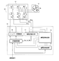
・過電流検出部18の異常を診断する際に用いられる過電流検査部19を備える点
・過電流検査部19を利用して過電流検出部18の異常を診断する機能を備える点
にある。他は図1に示した従来のモータ制御装置と同じであるため、同一符号を用いてその説明を省略する。 The motor control device shown in FIG. 2 differs from the conventional motor control device shown in FIG.
-The point provided with the overcurrent test |
Claims (6)
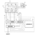
- モータ用のインバータに流れる電流の代替となる電圧を検出する電圧検出手段と、該電圧検出手段からの検出電圧と過電流判断用の基準電圧とを比較する過電流検出手段と、該過電流検出手段からの検出信号によって過電流の有無を判断する過電流判断手段と、を具備したモータ制御装置であって、
モータが回転していないときに前記基準電圧以上の検査電圧を前記検出電圧の代わりに過電流検出手段に送出する過電流検査手段と、
過電流検査手段からの検査電圧が過電流判断手段において過電流無しと判断されたときに過電流検出手段に異常が生じていると判断する異常診断手段と、を備える。 A voltage detection means for detecting a voltage that substitutes for the current flowing through the inverter for the motor; an overcurrent detection means for comparing a detection voltage from the voltage detection means with a reference voltage for overcurrent determination; and the overcurrent detection Overcurrent determination means for determining the presence or absence of overcurrent based on a detection signal from the means,
Overcurrent inspection means for sending an inspection voltage equal to or higher than the reference voltage to the overcurrent detection means instead of the detection voltage when the motor is not rotating;
An abnormality diagnosing unit that determines that an abnormality has occurred in the overcurrent detecting unit when the overcurrent determining unit determines that there is no overcurrent in the overcurrent determining unit. - 請求項1に記載のモータ制御装置において、
モータが回転していないときに前記基準電圧よりも低い第2の検査電圧を前記検出電圧の代わりに過電流検出手段に送出する第2の過電流検査手段と、
第2の過電流検査手段からの第2の検査電圧が過電流判断手段において過電流有りと判断されたときに過電流検出手段に異常が生じていると判断する第2の異常診断手段と、さらにを備える。 The motor control device according to claim 1,
Second overcurrent inspection means for sending a second inspection voltage lower than the reference voltage to the overcurrent detection means instead of the detection voltage when the motor is not rotating;
A second abnormality diagnosing unit for determining that an abnormality has occurred in the overcurrent detecting unit when the second inspection voltage from the second overcurrent inspecting unit is determined to be overcurrent in the overcurrent determining unit; Further provided. - 請求項1または2に記載のモータ制御装置において、
異常診断手段または第2の異常診断手段において過電流検出手段に異常が生じていると判断されたときに該異常を報知する異常報知手段を、さらに備える。 The motor control device according to claim 1 or 2,
An abnormality notifying means for notifying the abnormality when the abnormality diagnosing means or the second abnormality diagnosing means determines that an abnormality has occurred in the overcurrent detecting means is further provided. - 請求項1~3の何れか1項に記載のモータ制御装置において、
モータはステータに複数相のコイルを有する同期モータであり、インバータは同期モータの複数相のコイルに対応した複数相のスイッチング素子を有するインバータである。 The motor control device according to any one of claims 1 to 3,
The motor is a synchronous motor having a plurality of phase coils in the stator, and the inverter is an inverter having a plurality of phase switching elements corresponding to the plurality of phase coils of the synchronous motor. - 請求項4に記載のモータ制御装置において、
電圧検出手段は、インバータの各相に流れる電流の代替となる電圧を検出するためのシャント抵抗器から成る。 The motor control device according to claim 4,
The voltage detection means is composed of a shunt resistor for detecting a voltage that is an alternative to the current flowing in each phase of the inverter. - 請求項5に記載のモータ制御装置において、
同期モータが回転しているときに該同期モータの複数相のコイルそれぞれに流れる電流を検出する電流検出手段と、
電流検出手段からの検出電流の和が零でないときにシャント抵抗器に異常が生じていると判断する第3の異常診断手段と、をさらに備える。 The motor control device according to claim 5,
Current detection means for detecting a current flowing in each of the coils of the plurality of phases of the synchronous motor when the synchronous motor is rotating;
And a third abnormality diagnosing means for judging that an abnormality has occurred in the shunt resistor when the sum of the detected currents from the current detecting means is not zero.
Priority Applications (3)
| Application Number | Priority Date | Filing Date | Title |
|---|---|---|---|
| US13/322,247 US9024555B2 (en) | 2009-05-27 | 2010-05-27 | Motor control device |
| EP10780288.6A EP2432112B1 (en) | 2009-05-27 | 2010-05-27 | Motor control device |
| CN201080022361.6A CN102428640B (en) | 2009-05-27 | 2010-05-27 | Control device of electric motor |
Applications Claiming Priority (2)
| Application Number | Priority Date | Filing Date | Title |
|---|---|---|---|
| JP2009-127749 | 2009-05-27 | ||
| JP2009127749A JP5537837B2 (en) | 2009-05-27 | 2009-05-27 | Motor control device |
Publications (1)
| Publication Number | Publication Date |
|---|---|
| WO2010137328A1 true WO2010137328A1 (en) | 2010-12-02 |
Family
ID=43222454
Family Applications (1)
| Application Number | Title | Priority Date | Filing Date |
|---|---|---|---|
| PCT/JP2010/003564 WO2010137328A1 (en) | 2009-05-27 | 2010-05-27 | Motor control device |
Country Status (5)
| Country | Link |
|---|---|
| US (1) | US9024555B2 (en) |
| EP (1) | EP2432112B1 (en) |
| JP (1) | JP5537837B2 (en) |
| CN (1) | CN102428640B (en) |
| WO (1) | WO2010137328A1 (en) |
Cited By (3)
| Publication number | Priority date | Publication date | Assignee | Title |
|---|---|---|---|---|
| CN103078520A (en) * | 2011-10-26 | 2013-05-01 | 乐星产电(无锡)有限公司 | Frequency converter device and over-current protection method thereof |
| CN103959632A (en) * | 2011-11-21 | 2014-07-30 | 三电有限公司 | Fault detection device for inverter system |
| WO2020116374A1 (en) * | 2018-12-04 | 2020-06-11 | 日本電産株式会社 | Overcurrent detection device and motor unit |
Families Citing this family (19)
| Publication number | Priority date | Publication date | Assignee | Title |
|---|---|---|---|---|
| JP5880967B2 (en) * | 2012-09-28 | 2016-03-09 | 株式会社デンソー | AC motor control device |
| JP6201319B2 (en) * | 2013-01-15 | 2017-09-27 | 住友電気工業株式会社 | Converter, failure determination method, and control program |
| KR101707706B1 (en) | 2013-07-03 | 2017-02-16 | 엘에스산전 주식회사 | Protection device and operating verification metohd thereof |
| JP5939235B2 (en) * | 2013-11-26 | 2016-06-22 | 株式会社デンソー | Rotating electric machine driving device and electric power steering device using the same |
| JP2015104240A (en) * | 2013-11-26 | 2015-06-04 | 株式会社デンソー | Rotary electric machine driving device, and electric power steering device using the same |
| JP6225371B2 (en) * | 2013-12-24 | 2017-11-08 | 日本電産テクノモータ株式会社 | Motor drive device |
| JP6291352B2 (en) * | 2014-05-26 | 2018-03-14 | 日本電産サンキョー株式会社 | Motor control device and motor control method |
| JP6266451B2 (en) * | 2014-06-30 | 2018-01-24 | 日立オートモティブシステムズ株式会社 | Drive circuit device |
| US9941815B2 (en) * | 2014-08-04 | 2018-04-10 | Hitachi Automotive Systems, Ltd. | Power conversion apparatus with overcurrent simulating circuit |
| JP6157752B2 (en) * | 2014-09-09 | 2017-07-05 | 三菱電機株式会社 | Inverter device for driving multiphase AC motor |
| KR101993195B1 (en) | 2015-04-09 | 2019-06-26 | 엘에스산전 주식회사 | A method for detecting a ground fault of an inverter |
| JP6506644B2 (en) | 2015-07-09 | 2019-04-24 | 日立オートモティブシステムズ株式会社 | Drive unit |
| EP3340457B1 (en) * | 2015-08-19 | 2021-05-12 | NSK Ltd. | Electronic control device and electric power steering device equipped with same |
| JP6897025B2 (en) * | 2016-08-08 | 2021-06-30 | 株式会社アイシン | Motor control device |
| US10322748B2 (en) * | 2016-09-23 | 2019-06-18 | Jtekt Corporation | Motor controller and steering device |
| US11012011B2 (en) * | 2017-04-27 | 2021-05-18 | Mitsubishi Electric Corporation | Motor control device and air conditioner |
| JP7146688B2 (en) * | 2019-04-23 | 2022-10-04 | ルネサスエレクトロニクス株式会社 | Drive device and power supply system |
| JP7131510B2 (en) * | 2019-08-26 | 2022-09-06 | 株式会社デンソー | motor controller |
| JP7306237B2 (en) | 2019-11-22 | 2023-07-11 | 株式会社デンソー | power system |
Citations (6)
| Publication number | Priority date | Publication date | Assignee | Title |
|---|---|---|---|---|
| JPH0829470A (en) * | 1994-07-14 | 1996-02-02 | Yaskawa Electric Corp | Detecting method for failure of current detector |
| JP2001320894A (en) * | 2000-05-08 | 2001-11-16 | Matsushita Electric Ind Co Ltd | Motor drive device |
| JP2002325353A (en) | 2001-04-23 | 2002-11-08 | Sanyo Electric Co Ltd | Inverter protective device |
| JP2004173348A (en) * | 2002-11-18 | 2004-06-17 | Calsonic Kansei Corp | Electric motor control device |
| WO2005004319A1 (en) * | 2003-07-02 | 2005-01-13 | Kabushiki Kaisha Yaskawa Denki | Device and method for automatically performing inverter shipment test |
| JP2006160030A (en) * | 2004-12-06 | 2006-06-22 | Nsk Ltd | Electric power steering device |
Family Cites Families (9)
| Publication number | Priority date | Publication date | Assignee | Title |
|---|---|---|---|---|
| JPH1169865A (en) * | 1997-08-26 | 1999-03-09 | Toyota Motor Corp | Electric motor drive gear |
| JP2001157487A (en) * | 1999-11-26 | 2001-06-08 | Nissan Motor Co Ltd | Controller for electric rotating machine |
| JP2001238480A (en) * | 2000-02-21 | 2001-08-31 | Matsushita Electric Ind Co Ltd | Inverter device and electric washing machine using the same |
| JP2002291284A (en) * | 2001-03-26 | 2002-10-04 | Toshiba Kyaria Kk | Method for detecting current of motor and its controller |
| US6577087B2 (en) * | 2001-05-10 | 2003-06-10 | Ut-Battelle, Llc | Multilevel DC link inverter |
| US6737828B2 (en) * | 2001-07-19 | 2004-05-18 | Matsushita Electric Industrial Co., Ltd. | Washing machine motor drive device |
| JP4682727B2 (en) * | 2005-07-13 | 2011-05-11 | パナソニック株式会社 | Motor drive device |
| JP4643419B2 (en) * | 2005-11-08 | 2011-03-02 | 矢崎総業株式会社 | Load drive device with self-diagnosis function |
| JP2007333685A (en) * | 2006-06-19 | 2007-12-27 | Matsushita Electric Ind Co Ltd | Failure inspection apparatus |
-
2009
- 2009-05-27 JP JP2009127749A patent/JP5537837B2/en active Active
-
2010
- 2010-05-27 US US13/322,247 patent/US9024555B2/en active Active
- 2010-05-27 WO PCT/JP2010/003564 patent/WO2010137328A1/en active Application Filing
- 2010-05-27 EP EP10780288.6A patent/EP2432112B1/en active Active
- 2010-05-27 CN CN201080022361.6A patent/CN102428640B/en active Active
Patent Citations (6)
| Publication number | Priority date | Publication date | Assignee | Title |
|---|---|---|---|---|
| JPH0829470A (en) * | 1994-07-14 | 1996-02-02 | Yaskawa Electric Corp | Detecting method for failure of current detector |
| JP2001320894A (en) * | 2000-05-08 | 2001-11-16 | Matsushita Electric Ind Co Ltd | Motor drive device |
| JP2002325353A (en) | 2001-04-23 | 2002-11-08 | Sanyo Electric Co Ltd | Inverter protective device |
| JP2004173348A (en) * | 2002-11-18 | 2004-06-17 | Calsonic Kansei Corp | Electric motor control device |
| WO2005004319A1 (en) * | 2003-07-02 | 2005-01-13 | Kabushiki Kaisha Yaskawa Denki | Device and method for automatically performing inverter shipment test |
| JP2006160030A (en) * | 2004-12-06 | 2006-06-22 | Nsk Ltd | Electric power steering device |
Non-Patent Citations (1)
| Title |
|---|
| See also references of EP2432112A4 |
Cited By (4)
| Publication number | Priority date | Publication date | Assignee | Title |
|---|---|---|---|---|
| CN103078520A (en) * | 2011-10-26 | 2013-05-01 | 乐星产电(无锡)有限公司 | Frequency converter device and over-current protection method thereof |
| CN103959632A (en) * | 2011-11-21 | 2014-07-30 | 三电有限公司 | Fault detection device for inverter system |
| US9360515B2 (en) | 2011-11-21 | 2016-06-07 | Sanden Corporation | Fault detection device for inverter system |
| WO2020116374A1 (en) * | 2018-12-04 | 2020-06-11 | 日本電産株式会社 | Overcurrent detection device and motor unit |
Also Published As
| Publication number | Publication date |
|---|---|
| US20120074885A1 (en) | 2012-03-29 |
| JP5537837B2 (en) | 2014-07-02 |
| CN102428640A (en) | 2012-04-25 |
| CN102428640B (en) | 2015-09-09 |
| EP2432112A4 (en) | 2014-10-22 |
| EP2432112A1 (en) | 2012-03-21 |
| JP2010279125A (en) | 2010-12-09 |
| EP2432112B1 (en) | 2016-07-20 |
| US9024555B2 (en) | 2015-05-05 |
Similar Documents
| Publication | Publication Date | Title |
|---|---|---|
| JP5537837B2 (en) | Motor control device | |
| US8232752B2 (en) | Electric motor control apparatus | |
| US7719217B2 (en) | Drive device for a brushless motor | |
| JP6157752B2 (en) | Inverter device for driving multiphase AC motor | |
| US10071762B2 (en) | Detection and mitigation of inverter errors in steering system motors | |
| US10673364B2 (en) | Motor control method, motor drive system, and electric power steering system | |
| US8536877B2 (en) | Power cable breaking detection method of motor | |
| EP2037566A1 (en) | Multi-phase AC motor driving device | |
| US11063545B2 (en) | Power conversion device, motor module, and electric power steering device | |
| US20200028463A1 (en) | Motor driving device and steering system | |
| JP2019193473A (en) | Motor control device and electric power steering device | |
| US11472472B2 (en) | Power conversion device, motor module, and electric power steering device | |
| JP2005160136A (en) | Inverter device and automobile equipped with it | |
| JPWO2016021329A1 (en) | Power converter | |
| JP2014054927A (en) | Power steering device | |
| JP2000253687A (en) | Servo device | |
| JP6911570B2 (en) | Detection device | |
| JP5169187B2 (en) | Inverter short-circuit element determination device | |
| JP4565963B2 (en) | Failure detection processor | |
| CN109951135B (en) | Power control unit | |
| JP2000125586A (en) | Method and device for diagnosing failures | |
| JP3684940B2 (en) | Anomaly detection system | |
| JP2017093196A (en) | Inverter controller and short-circuit inspection method for motor | |
| KR102159110B1 (en) | Apparatus for driving motor for a vehicle | |
| JP2009254083A (en) | Abnormality detector for motor output circuit |
Legal Events
| Date | Code | Title | Description |
|---|---|---|---|
| WWE | Wipo information: entry into national phase |
Ref document number: 201080022361.6 Country of ref document: CN |
|
| 121 | Ep: the epo has been informed by wipo that ep was designated in this application |
Ref document number: 10780288 Country of ref document: EP Kind code of ref document: A1 |
|
| WWE | Wipo information: entry into national phase |
Ref document number: 13322247 Country of ref document: US |
|
| NENP | Non-entry into the national phase |
Ref country code: DE |
|
| REEP | Request for entry into the european phase |
Ref document number: 2010780288 Country of ref document: EP |
|
| WWE | Wipo information: entry into national phase |
Ref document number: 2010780288 Country of ref document: EP |