WO2010134599A1 - 摺動接点の製造方法 - Google Patents
摺動接点の製造方法 Download PDFInfo
- Publication number
- WO2010134599A1 WO2010134599A1 PCT/JP2010/058634 JP2010058634W WO2010134599A1 WO 2010134599 A1 WO2010134599 A1 WO 2010134599A1 JP 2010058634 W JP2010058634 W JP 2010058634W WO 2010134599 A1 WO2010134599 A1 WO 2010134599A1
- Authority
- WO
- WIPO (PCT)
- Prior art keywords
- prepreg
- sliding contact
- manufacturing
- resin
- laser
- Prior art date
- Legal status (The legal status is an assumption and is not a legal conclusion. Google has not performed a legal analysis and makes no representation as to the accuracy of the status listed.)
- Ceased
Links
Images


Classifications
-
- H—ELECTRICITY
- H01—ELECTRIC ELEMENTS
- H01R—ELECTRICALLY-CONDUCTIVE CONNECTIONS; STRUCTURAL ASSOCIATIONS OF A PLURALITY OF MUTUALLY-INSULATED ELECTRICAL CONNECTING ELEMENTS; COUPLING DEVICES; CURRENT COLLECTORS
- H01R13/00—Details of coupling devices of the kinds covered by groups H01R12/70 or H01R24/00 - H01R33/00
- H01R13/02—Contact members
- H01R13/03—Contact members characterised by the material, e.g. plating, or coating materials
-
- H—ELECTRICITY
- H01—ELECTRIC ELEMENTS
- H01C—RESISTORS
- H01C10/00—Adjustable resistors
- H01C10/30—Adjustable resistors the contact sliding along resistive element
-
- H—ELECTRICITY
- H01—ELECTRIC ELEMENTS
- H01H—ELECTRIC SWITCHES; RELAYS; SELECTORS; EMERGENCY PROTECTIVE DEVICES
- H01H1/00—Contacts
- H01H1/02—Contacts characterised by the material thereof
- H01H1/021—Composite material
- H01H1/027—Composite material containing carbon particles or fibres
-
- H—ELECTRICITY
- H01—ELECTRIC ELEMENTS
- H01H—ELECTRIC SWITCHES; RELAYS; SELECTORS; EMERGENCY PROTECTIVE DEVICES
- H01H1/00—Contacts
- H01H1/12—Contacts characterised by the manner in which co-operating contacts engage
- H01H1/36—Contacts characterised by the manner in which co-operating contacts engage by sliding
- H01H1/44—Contacts characterised by the manner in which co-operating contacts engage by sliding with resilient mounting
-
- H—ELECTRICITY
- H01—ELECTRIC ELEMENTS
- H01H—ELECTRIC SWITCHES; RELAYS; SELECTORS; EMERGENCY PROTECTIVE DEVICES
- H01H11/00—Apparatus or processes specially adapted for the manufacture of electric switches
- H01H11/04—Apparatus or processes specially adapted for the manufacture of electric switches of switch contacts
-
- H—ELECTRICITY
- H01—ELECTRIC ELEMENTS
- H01R—ELECTRICALLY-CONDUCTIVE CONNECTIONS; STRUCTURAL ASSOCIATIONS OF A PLURALITY OF MUTUALLY-INSULATED ELECTRICAL CONNECTING ELEMENTS; COUPLING DEVICES; CURRENT COLLECTORS
- H01R39/00—Rotary current collectors, distributors or interrupters
- H01R39/02—Details for dynamo electric machines
- H01R39/18—Contacts for co-operation with commutator or slip-ring, e.g. contact brush
- H01R39/24—Laminated contacts; Wire contacts, e.g. metallic brush, carbon fibres
-
- H—ELECTRICITY
- H01—ELECTRIC ELEMENTS
- H01R—ELECTRICALLY-CONDUCTIVE CONNECTIONS; STRUCTURAL ASSOCIATIONS OF A PLURALITY OF MUTUALLY-INSULATED ELECTRICAL CONNECTING ELEMENTS; COUPLING DEVICES; CURRENT COLLECTORS
- H01R43/00—Apparatus or processes specially adapted for manufacturing, assembling, maintaining, or repairing of line connectors or current collectors or for joining electric conductors
- H01R43/16—Apparatus or processes specially adapted for manufacturing, assembling, maintaining, or repairing of line connectors or current collectors or for joining electric conductors for manufacturing contact members, e.g. by punching and by bending
-
- H—ELECTRICITY
- H01—ELECTRIC ELEMENTS
- H01H—ELECTRIC SWITCHES; RELAYS; SELECTORS; EMERGENCY PROTECTIVE DEVICES
- H01H11/00—Apparatus or processes specially adapted for the manufacture of electric switches
- H01H11/04—Apparatus or processes specially adapted for the manufacture of electric switches of switch contacts
- H01H11/06—Fixing of contacts to carrier ; Fixing of contacts to insulating carrier
Definitions
- the present invention relates to a method for manufacturing a sliding contact provided with a carbon fiber bundle.
- Patent Document 1 discloses a sliding contact used for a potentiometer or the like.
- This type of sliding contact is configured to be bent in, for example, a U-shape, and the bent portion (support portion) is insulated and the sliding ends at both ends are brought into contact with the conductive pattern.
- Patent Document 1 discloses a sliding contact provided with a carbon fiber aggregate (carbon fiber bundle).
- Patent Document 1 discloses a configuration in which a carbon fiber bundle is covered with a resin layer, but does not disclose a detailed manufacturing method.
- the manufacturing method is not considered, and therefore the productivity is poor. Accordingly, the present invention is for solving the above-described conventional problems, and in particular, a sliding contact manufacturing method that can be easily and stably molded into a predetermined shape with high productivity in a sliding contact including a carbon fiber bundle. It is intended to provide.
- the manufacturing method of the sliding contact in the present invention includes a prepreg forming step of forming a prepreg by impregnating a carbon fiber bundle with a resin, And a molding step of performing hot pressing in a state where release sheets are arranged on both surfaces of the prepreg.
- the prepreg includes not only a carbon fiber bundle impregnated with a thermosetting resin but also a carbon fiber bundle impregnated with a thermoplastic resin.
- a release sheet is interposed between the prepreg and the press machine, so that the prepreg can be appropriately hot-pressed, and the sliding contact provided with the carbon fiber bundle is easier and more productive than before. And it can be stably formed into a predetermined shape.
- the hot pressing after the laser processing step of irradiating the prepreg with laser to cut it into a predetermined contact shape.
- a contact shape can be demarcated by laser irradiation simply and appropriately to a flat prepreg, and the prepreg can be appropriately cut by laser irradiation.
- the prepreg is hot-pressed to appropriately three-dimensionally form the sliding contact with the defined outer shape.
- the laser processing step is performed on the other surface of the prepreg, and then the release sheet is disposed on both surfaces of the prepreg. It is preferable to perform the hot pressing. Accordingly, the prepreg can be supported on the transparent base surface, and laser processing can be performed on the prepreg with high accuracy.
- the base is preferably glass. Thereby, deformation of the base can be prevented even by laser irradiation, the prepreg can be stably supported on the base, and laser processing can be performed on the prepreg with higher accuracy.
- the base may be configured by one of the release sheets disposed on both sides of the prepreg before the hot press forming step.
- the laser passes through the release sheet during laser processing, and only the prepreg can be appropriately cut. Further, it is not necessary to separately prepare a base for supporting the prepreg during laser processing.
- the release sheet is a carrier tape
- the carrier tape is supplied to both sides of the prepreg, and the prepreg sandwiched between the carrier tapes is conveyed. Then, it is preferable to apply the hot press.
- the hot pressing can be appropriately performed with high productivity, and the prepreg can be used with the carrier tape. Can be transported.
- the sliding contact connected to the belt-like body can be stored in a state where the carrier tape is arranged on both surfaces, and the sliding contact can be appropriately protected until just before use. Therefore, the sliding contact is less likely to cause problems such as mechanical damage (bending or breakage) and contamination. Moreover, the handling property of the sliding contact can be improved.
- the prepreg when defined as a contact shape in the laser processing step, it is preferable to leave the connecting portion in a portion other than the contact portion. This makes it possible to produce a stable quality sliding contact and improve productivity when the connection part is cut in order to separate the sliding contact from the strip, and the contact part is not damaged by cutting. Can do.
- the resin is preferably a thermosetting resin.
- molding process can be simultaneously performed by compression with heat curing of resin.
- the thermosetting resin is preferably an epoxy resin.
- the thermosetting resin includes triphenyl glycidyl ether methane (Tri-PGEM), cresol novolac epoxy, tetraglycidyl diaminophenyl methane (Tet-GDDM), tetraphenyl glycidyl ether ethane (Tet-PGEE). It is preferable to use at least one of them and at least one of diaminodiphenylsulfone (DDS), acid anhydride, and dicyandiamide (DICY) as a curing agent.
- the glass transition point (glass transition temperature) Tg can be made higher than that of a normal epoxy resin, the heat resistance of the sliding contact can be improved, and high spring properties and stable electrical characteristics can be obtained even at high operating temperatures. Can be manufactured.
- the present invention in a manufacturing method of a sliding contact provided with a carbon fiber bundle, it can be easily and stably formed into a predetermined shape with high productivity.
- Process drawing which shows the manufacturing method of the sliding contact of this embodiment
- the perspective view which shows an example of the sliding contact manufactured by the manufacturing process shown in FIG. Explanatory drawing which shows the state which made the series of processes shown in FIG. 1 into a line
- Process drawing which shows the manufacturing method of the sliding contact of embodiment different from FIG.
- Process drawing which shows the manufacturing method of the sliding contact performed after FIG. Explanatory drawing which shows the state which made the series of processes shown in FIG. 4, FIG. 5 into a line
- the perspective view of the sliding contact of this embodiment obtained from FIG. Sectional view showing the connection structure of the sliding contact,
- the schematic diagram which shows the cross-sectional structure of the sliding edge vicinity of a sliding contact.
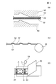
- FIG. 1 is a process diagram showing a method of manufacturing a sliding contact according to this embodiment. Each figure is a schematic diagram, but (e) and (f) are hatched as sectional views.
- a carbon fiber bundle 10 in which 1000 to 10,000 carbon fibers are bundled is wound around a bobbin 20.
- yen shown to Fig.1 (a) expands and shows the carbon fiber bundle 10.
- FIG. The carbon fiber bundle 10 is obtained by lightly bonding a large number of carbon fibers with a sizing material.
- the surface of the carbon fiber bundle 10 is impregnated with a solution 21 of a thermosetting resin.
- a solution 21 of a thermosetting resin for example, there is a method of spraying a thermosetting resin solution 21 or immersing the carbon fiber bundle 10 in the solution.
- FIG.1 (b) is the figure which has sprayed the solution 21 of the thermosetting resin.
- thermosetting resin triphenyl glycidyl ether methane (Tri-PGEM), cresol novolac epoxy, tetraglycidyl diaminophenyl methane (Tet-GDDM), tetraphenyl glycidyl ether are used. It is preferable to use at least one of ethane (Tet-PGEE) and at least one of diaminodiphenylsulfone (DDS), acid anhydride, and dicyandiamide (DICY) as a curing agent.
- Tri-PGEM triphenyl glycidyl ether methane
- DDS diaminodiphenylsulfone
- DIY dicyandiamide
- DDS diaminodiphenylsulfone
- Tri-PGEM triferyl glycidyl ether methane
- the solvent is removed by a drying process.
- the flat prepreg 22 in which the carbon fiber bundle 10 is impregnated with the uncured thermosetting resin can be molded.
- the prepreg 22 is placed on the release sheet 23.
- the release sheet 23 is preferably transparent and excellent in heat resistance.
- a fluororesin film for example, Aflex (registered trademark) manufactured by Asahi Glass Co., Ltd.
- the release sheet 23 can be disposed on both surfaces of the prepreg 22, but in the process of FIG. 1C, if the release sheet 23 is disposed on at least one surface of the prepreg 22. Good.
- the prepreg 22 is cut into a predetermined shape using, for example, a YAG laser.
- the YAG laser is preferably of a type called FAYb that amplifies the laser with ytterbium.
- the wavelength of the YAG laser is, for example, about 1024 nm.
- the laser L is irradiated from the exposed surface side of the prepreg 22 (the side opposite to the surface on which the release sheet 23 is disposed) as shown in FIG.
- the laser L passes through the release sheet 23, and the release sheet 23 is not cut, and only the prepreg 22 can be cut.
- the laser L passes through one release sheet 23 before reaching the prepreg 22, but the release mold 23 Since the prepreg 22 may not be accurately cut into a predetermined shape due to the diffusion of the laser L in the sheet 23, when the release sheets 23 are arranged on both sides of the prepreg 22 in the step of FIG. In the laser processing step of FIG. 1D, it is necessary to remove one release sheet 23 once.
- release sheets 23 and 24 are arranged on both sides of the prepreg 22.
- the release sheet 24 is disposed on the other side.
- the newly added release sheet 24 does not need to be transparent like the release sheet 23, but it is preferable to use the same material as the release sheet 23 because the sheet characteristics can be made the same. .
- the prepreg 22 can be three-dimensionally formed by hot pressing, and at this time, the whole can be made into a thin flat shape with a substantially constant thickness.
- the heat treatment temperature is about several hundred degrees (100 ° C. to 250 ° C.), and the heat treatment time is about several tens of minutes to several hours (10 minutes to 90 minutes).
- the release sheets 23 and 24 are interposed between the prepreg 22 and the heat press machine 26 so that the uncured thermosetting resin does not contact the heat press machine 26 and the resin layer 11 ( 9) will not adhere to the hot press 26 side. Therefore, the prepreg 22 can be appropriately hot-pressed and can be three-dimensionally formed into a predetermined shape appropriately and easily.
- FIG. 2 shows an example of the sliding contact 30 formed by the manufacturing method shown in FIG. As shown in FIG. 2, the sliding contact 30 has a plurality of sliding ends 30a to 30f. Each sliding end 30a to 30f is formed, for example, in a bifurcated manner in order to obtain stable electrical characteristics.
- the sliding contact 30 shown in FIG. 2 can be used as one sliding contact.
- a plurality of sliding contacts can be obtained by cutting along the dotted line E shown in FIG.
- a sliding contact 1 obtained by cutting along the dotted line E in FIG. 2 is shown in FIG.
- FIG. 3 shows an example in which the manufacturing process of the sliding contact is lined up.
- the carbon fiber bundle 10 wound around the bobbin 20 is pulled out and immersed in a resin solution 41 in which a thermosetting resin is dissolved in a solvent.
- a hot air dryer 42 is prepared, and the carbon fiber bundle 10 impregnated with the resin is dried to form the prepreg 22.
- carrier tapes 48 and 49 are supplied to both surfaces of the prepreg 22.
- the carrier tapes 48 and 49 are preferably transparent films having high heat resistance and high releasability, such as fluorine films, like the release sheets 23 and 24 shown in FIGS. 3D, a positioning press 45 is prepared, and positioning holes are provided in the prepreg 22 with a carrier tape.
- the positioning holes formed by this process are indicated by reference numerals 30g and 30h in FIG.
- the positioning holes 30g and 30h are for controlling the position of laser cutting in the next process and the position with respect to the hot press.
- step (e) of FIG. 3 the carrier tape 49 disposed on the upper surface side of the prepreg 22 is once peeled off, and the exposed surface of the prepreg 22 is subjected to laser processing by the laser irradiation machine 46 to be slid. Define the outline of the moving contact.
- the carrier tape 48 on the lower surface side of the prepreg 22 is transparent and transmits a laser, so that it is not cut and can be used for transporting the prepreg 22 as it is.
- the carrier tape 49 is supplied to the upper surface of the prepreg 22 between the step of FIG. 3E and the step of FIG.
- carrier tapes 48 and 49 are arranged on both surfaces of the prepreg 22, but the carrier tape 49 on one side of the prepreg 22 is between the steps of FIG. 3 (e) and FIG. 3 (f). It can also be supplied for the first time.
- the carrier tapes 48 and 49 are disposed on both sides of the prepreg 22 and are conveyed to a molding process by the hot press machine 26 in the process of FIG.
- the prepreg 22 is subjected to heat pressing, thereby heat curing the uncured thermosetting resin and three-dimensional molding by compression.
- carrier tapes 48 and 49 are disposed on both surfaces of the prepreg 22 and the carrier tapes 48 and 49 have high heat resistance.
- Carrier tapes 48 and 49 can be appropriately interposed between the prepreg 22 and the hot press machine 26 during the pressing process. 3G, the carrier tapes 48 and 49 are removed from both surfaces of the three-dimensionally formed sliding contact. At this time, since the carrier tapes 48 and 49 have high releasability, the carrier tapes 48 and 49 can be easily and appropriately removed from both surfaces of the sliding contact.
- the release sheets 23 and 24 are arranged on both surfaces of the prepreg 22 in which the carbon fiber bundle 10 is impregnated with resin.
- step (e) in FIG. 1, step (f) in FIG. 3 There is a characteristic part in the point of hot pressing (step (e) in FIG. 1, step (f) in FIG. 3).
- thermosetting resin used as the resin
- thermosetting resin it is possible to simultaneously perform molding by compression together with heat curing of the resin by hot pressing.
- Tg the thing of the high glass transition point
- the resin impregnated in the carbon fiber bundle 10 is not limited to a thermosetting resin, and may be a thermoplastic resin.
- a thermoplastic resin When a thermoplastic resin is used as the resin, it may be a molten resin that is made liquid by heating the thermoplastic resin instead of the resin solution 41 in the step of FIG. The drying process by the hot air dryer 42 can be omitted.
- the molding process by the heat press machine 26 in FIG. 3 (f) is a process in which the resin (thermoplastic resin) in the prepreg formed by impregnating the carbon fiber bundle 10 with the thermoplastic resin is heated and deformed, and therefore the time is short. Can be molded by hot pressing.
- the thermoplastic resin include polyamide resin, PPS resin, PBT resin, and the like.
- the contact shape can be defined easily and appropriately by laser irradiation on the flat prepreg 22, and the prepreg 22 can be appropriately cut by laser irradiation. Then, after defining the planar shape of the contact, the prepreg 22 is hot-pressed to appropriately three-dimensionally form the sliding contact with the defined outer shape.
- the prepreg 22 is placed on a transparent carrier tape 48 and conveyed to the laser processing step, and then the carrier tape 48, 49 can be transported to the hot press molding process.
- the transparent carry tape 48 is not cut in the laser processing step, the prepreg 22 cut into a predetermined shape can be appropriately conveyed to the hot press step.
- the carrier tape 48 can be used as a base for the prepreg 22 in the laser processing step, and laser processing can be performed without preparing the base separately.
- the hot pressing can be performed appropriately, and thus a series of steps are performed.
- a line can be formed by carrying the prepreg 22 by carrier tapes 48 and 49.
- FIG. 4 and 5 are process diagrams showing a method for manufacturing a sliding contact in another embodiment.
- the carbon fiber bundle 10 wound around the bobbin 20 shown in the step of FIG. 4A is pulled out, and as shown in FIG. 4B, a solution 21 of a thermosetting resin is applied to the surface of the carbon fiber bundle 10. Impregnate. Subsequently, the solvent is removed by a drying process.
- the plate-like prepreg 22 in which the carbon fiber bundle 10 is impregnated with the uncured thermosetting resin can be formed as a strip.
- the strip-shaped prepreg 22 is transported and placed on the glass plate 50 as shown in the left figure (partial sectional view) of FIG.
- the right figure of FIG.4 (c) has shown the partial top view.
- the laser irradiator 51 irradiates a laser L to cut out the prepreg 22 into the shape of a sliding contact.
- the laser L is preferably a YAG laser, as described in the step of FIG.
- the laser L is irradiated to the exposed surface side (opposite surface side with respect to the surface which has arrange
- the prepreg 22 is cut into the shape A of the sliding contact by laser processing.
- the shape A of the sliding contact is defined by the contact part B and the non-contact part C other than the contact part B.
- the contact portion B includes at least the contact portion B1 that defines the outer shape of the sliding ends 30a to 30f shown in FIG. 2, and is preferably on the left side (cut along the dotted line E shown in FIG. It refers to the entire outline of the sliding contact on the remaining side. Therefore, the non-contact part C is preferably the outer shape on the right side of the drawing (the side removed by cutting along the dotted line E) with respect to the dotted line E shown in FIG.
- the prepreg 22 is cut into the shape A of the sliding contact while leaving the connection portion D with the belt-like body.
- FIG. 4 (c) it is possible to provide the connecting portion D at a position opposite to the contact portion B1 that defines the outer shape of the sliding ends 30a to 30f, and to move the connecting portion D away from the contact portion B1. Is preferred.
- the prepreg 22 is separated on both sides.
- the moldable carrier tapes 52 and 52 are arranged and conveyed to the hot press process.
- the prepreg 22 with a carrier tape is hot-pressed by a hot press machine 56, and the prepreg 22 is three-dimensionally formed.
- the uncured thermosetting resin is cured, and a molded body of the prepreg 22 is obtained.
- the cured prepreg 22 with a carrier tape (molded product of the prepreg 22) is wound around a bobbin (reel) 53.
- the strip-shaped prepreg 22 formed by connecting the sliding contacts can be stored in a state where the carrier tapes 52 and 52 are arranged on both sides, and the sliding contacts can be appropriately used until just before using the sliding contacts. Can be protected. Therefore, the sliding contact is less likely to cause problems such as mechanical damage (bending or breakage) and contamination. In addition, handling properties can be improved.
- the molded body of the prepreg 22 with the carrier tape wound around the bobbin 53 is pulled out, and the molded body of the prepreg 22 as shown in FIG.
- the carrier tape 52 arranged on one side is peeled off, and the connection portion D is cut by the laser L using the laser irradiator 58.
- the laser L it is preferable to use a YAG laser as in the step of FIG. Thereby, compared with the case where the connection location D is cut with a mold or the like, damage to the sliding contact can be reduced, and the productivity of the sliding contact can be improved.
- the molded body of the prepreg 22 is also denoted by reference numeral 22 for convenience.
- FIG. 6 is an example in which the series of steps of FIGS. 4 and 5 are lined up.
- 6A is a process in which the carbon fiber bundle 10 wound around the bobbin (reel) 20 is pulled out and immersed in a resin solution 41 in which a thermosetting resin is dissolved in a solvent.
- 6B a hot air dryer 42 is prepared, and the carbon fiber bundle 10 impregnated with the resin is dried to form the prepreg 22 as a strip.
- FIG. 6C the prepreg 22 is transported and placed on the glass plate 50, and the prepreg 22 is irradiated with a laser L by a laser irradiator 51 to form the prepreg 22 into a predetermined sliding contact shape. Disconnect.
- FIG. 6A is a process in which the carbon fiber bundle 10 wound around the bobbin (reel) 20 is pulled out and immersed in a resin solution 41 in which a thermosetting resin is dissolved in a solvent.
- 6B a hot air dryer 42 is prepared, and
- the prepreg 22 is cut into the shape A of the sliding contact while leaving the connection portion D with the belt-like body. At this time, it is preferable to leave the connection location D on the non-contact part C side. It is more preferable to leave the connecting portion D at a position opposite to the contact portion B1 that defines the outer shape of the sliding ends 30a to 30f.
- the positioning holes 55 and 55 can be laser processed as shown in FIG. 6 (d).
- the carrier tape 52 is supplied to both surfaces of the prepreg 22.
- the carrier tape 52 is preferably, for example, a fluorine film having high heat resistance and releasability.
- the carrier tape 52 may be transparent, translucent, or opaque. However, it is preferable that it is transparent because handling properties and the like can be improved.
- the prepreg 22 with the carrier tape is transported to a molding process by the hot press machine 56.
- the heat press machine 56 is provided with a positioning protrusion 57, and the positioning hole 55 formed in the prepreg 22 shown in FIG. 6D is inserted into the positioning protrusion 57 of the heat press machine 56 to heat the prepreg 22. Positioning with respect to the press machine 56 is performed.
- the positioning hole 55 is not formed in the laser processing step of FIG. 6C, the tip of the positioning projection 57 provided in the heat press machine 56 is sharpened, and the positioning projection 57 is provided with a carrier tape.
- a hole may be formed in the prepreg 22. In the present embodiment, it is possible to perform positioning between the prepreg 22 with a carrier tape 22 and the hot press machine 56 with high accuracy in the hot press process.
- the positioning projection is not shown in the heat press machine 26 in FIG. 3F, the positioning projection is also provided in the heat press machine 26 in FIG.
- the prepreg 22 is hot-pressed to heat and cure the uncured thermosetting resin and to form a solid by compression.
- the carrier tape 52 is disposed on both surfaces of the prepreg 22 and the carrier tape 52 has high heat resistance, the carrier tape 52 is not melted even in the hot press process, and the prepreg 22 is not melted in the hot press process.
- the carrier tape 52 can be appropriately interposed between the heat press machine 56 and the heat press machine 56. 6G, the molded body of the prepreg 22 with a carrier tape is wound around the bobbin 53.
- the sliding contact is used, as described with reference to FIG. 5C, the molded body of the prepreg 22 with the carrier tape is pulled out from the bobbin 53, and the carrier tape 52 on one side is peeled off to form the molded body of the prepreg 22.
- the sliding contact can be taken out by cutting the connecting portion D with the strip-shaped body by the laser L.
- hot pressing is performed in a state where the releaseable carrier tapes 52 and 52 are arranged on both surfaces of the prepreg 22 ( Step of FIG. 5A, step of FIG. 6F).
- the prepreg 22 can be appropriately hot-pressed. Can be formed into a shape.
- thermosetting resin is used as the resin.
- thermosetting resin it is possible to simultaneously perform molding processing by compression as well as heat curing of the resin by hot pressing. Moreover, since the glass transition temperature Tg can be raised, the heat resistance of the sliding contact can also be improved.
- the resin impregnated in the carbon fiber bundle 10 is not limited to a thermosetting resin, and may be a thermoplastic resin.
- a thermoplastic resin When a thermoplastic resin is used as the resin, it may be a molten resin that is made liquid by heating the thermoplastic resin instead of the resin solution 41 in the step of FIG. 6 (a).
- the drying process by the hot air dryer 42 can be omitted.
- the molding process by the heat press machine 56 in FIG. 6 (f) is a process in which the resin (thermoplastic resin) in the prepreg formed by impregnating the carbon fiber bundle 10 with the thermoplastic resin is heated and deformed. Can be molded by hot pressing.
- the thermoplastic resin include polyamide resin, PPS resin, PBT resin, and the like.
- the prepreg 22 is disposed on the glass plate 50 and laser processing is performed. Thereby, even if laser irradiation is performed, the glass plate (base) 50 is not deformed, the prepreg 22 can be stably supported on the glass plate 50, and laser processing can be performed on the prepreg 22 with higher accuracy. is there.
- the sliding contact is made in the state where the connection portion D with the belt-like body is left in the prepreg 22.
- the shape A is cut.
- connection portion D in a portion other than the contact portion B (non-contact portion C).
- the contact part B is not damaged at the time of separation and a stable quality sliding contact is manufactured. can do.
- the sliding contact 1 shown in FIG. 7 formed by each manufacturing method described above extends from the support end 2 so as to be elastically deformable, and the tip thereof is three-dimensionally formed as the sliding end 3.
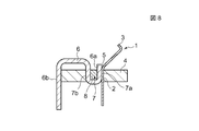
- the sliding contact 1 shown in FIG. 7 is supported and fixed to the support substrate 4 as shown in FIG.
- the sliding contact 1 has a three-dimensional shape inclined from the bent portion 5.
- a portion between the bent portion 5 and the sliding end 3 mainly functions as an elastically deformable region.
- the sliding end 3 is bent, it does not need to be bent.
- the support substrate 4 is provided with a metal terminal 6 that contacts the support end 2 of the sliding contact 1.
- the metal terminal 6 is entirely made of metal and is cut by a press, for example.
- One end of the metal terminal 6 is an abutting portion 6 a that abuts on the support end 2 of the sliding contact 1, and the other end is an external connection end 6 b that is drawn out and electrically connected to the external connection portion.
- the support substrate 4 is provided with a recess 7, and of the opposing side wall surfaces 7 a and 7 b of the recess 7, the support end 2 and the metal terminal 6 of the sliding contact 1 are formed on one side wall surface 7 a.
- the abutting portion 6a is in abutment with the abutting portion 6a.
- the fixing member 8 is press-fitted into the recess 7 formed in the support substrate 4, and the support end 2 and the contact portion 6a are in close contact with each other.
- the fixing member 8 is preferably an elastic member, whereby the contact portion 6a can be pressed in the direction of the support end 2 by pressing the fixing member 8 into the recess 7 as shown in FIG. At this time, it is preferable that the carbon fiber bundle 10 is exposed on the surface of the support end 2 so that the contact portion 6a and the support end 2 can be appropriately electrically connected.
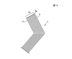
- the sliding contact 1 of this embodiment includes a carbon fiber bundle 10 in which the entire sliding end 3 from the supporting end 2 shown in FIG. 7 extends from the supporting end 2 to the sliding end 3.
- the resin layer 11 is impregnated in the carbon fiber bundle 10 and is molded with a substantially constant thickness.
- the sliding contact 1 is formed with a thickness of about 10 to 500 ⁇ m.
- the carbon fiber bundle 10 and the resin layer 11 impregnated in the carbon fiber bundle 10 are extended from the support end 2 at one end so as to be elastically deformable, and to the sliding end 3 at the tip.
- the three-dimensional structure having a substantially constant thickness is provided, so that the sliding contact 1 having excellent spring properties and stable electric characteristics can be obtained.
- wear is not required between the sliding end 3 of the sliding contact 1 and the resistance board of the variable resistor or the code board of the encoder without oil or the like in order to improve lubricity. It is possible to make the structure difficult to do.
- thermosetting resin is cured by hot pressing, or the thermoplastic resin is heated and deformed, and the three-dimensional molding is easily performed with a thin flat mold having a substantially constant thickness by compression.
- the side surface in the extending direction from the support end 2 to the sliding end 3 and the sliding surface 3a of the sliding end 3 are laser processed.
- the tip of the carbon fiber bundle 10 can be appropriately exposed together with the resin layer 11 on the sliding surface 3a of the sliding end 3, as shown in FIG. Can be obtained.
- the sliding contact 1 of this embodiment can be used for a variable resistor, an encoder, or the like.
Landscapes
- Engineering & Computer Science (AREA)
- Manufacturing & Machinery (AREA)
- Microelectronics & Electronic Packaging (AREA)
- Chemical & Material Sciences (AREA)
- Composite Materials (AREA)
- Materials Engineering (AREA)
- Reinforced Plastic Materials (AREA)
Abstract
【課題】 特に、炭素繊維束を備える電気接点において、生産性良く簡単且つ安定して所定形状に成形できる電気接点の製造方法を提供することを目的としている。 【解決手段】 本実施形態の電気接点の製造方法では、炭素繊維束(10)を熱硬化性樹脂に含浸したプリプレグ(22)の両面に離型シート(23),(24)を配置した状態で熱プレスする点に特徴的部分がある。これにより加熱硬化とともに圧縮を同時にでき、しかもプリプレグ(22)とプレス機(26)の間に離型シート(23),(24)が介在するのでプリプレグ(22)に対して熱プレスを適切に行うことができ、従来に比べて生産性良く簡単且つ安定して所定形状に成形できる。
Description
本発明は、炭素繊維束を備える摺動接点の製造方法に関する。
下記特許文献1には、ポテンショメータ等に用いられる摺動接点が開示されている。この種の摺動接点は例えばU字状に折り曲げられ、その折り曲げられた部分(支持部)を絶縁的に保持して両端の摺動端を導電パターン上に当接させる構成である。
そして特許文献1には、カーボンファイバ集合体(炭素繊維束)を備えた摺動接点が開示されている。
また、特許文献1には炭素繊維束を樹脂層で被覆する構成も開示されているが、詳細な製造方法の開示はない。
特許文献1に示された従来構成の摺動接点においては、その製造方法については考慮がなされておらず、したがって、生産性に乏しいものであった。そこで本発明は、上記従来の課題を解決するためのものであり、特に、炭素繊維束を備える摺動接点において、生産性良く簡単且つ安定して所定形状に成形できる摺動接点の製造方法を提供することを目的としている。
本発明における摺動接点の製造方法は、炭素繊維束に樹脂を含浸させてプリプレグを形成するプリプレグ形成工程と、
前記プリプレグの両面に離型シートを配置した状態で熱プレスする成形工程と、を有することを特徴とするものである。
前記プリプレグの両面に離型シートを配置した状態で熱プレスする成形工程と、を有することを特徴とするものである。
なお、本発明(本明細書)において、プリプレグとは、炭素繊維束に熱硬化性樹脂を含浸させたもののほか、炭素繊維束に熱可塑性樹脂を含浸させたものも含まれる。
これにより、プリプレグとプレス機の間に離型シートが介在するので、プリプレグに対して熱プレスを適切に行うことができ、炭素繊維束を備える摺動接点において、従来に比べて生産性良く簡単且つ安定して所定形状に成形できる。
本発明では、前記プリプレグにレーザ照射して所定の接点形状に切断するレーザ加工工程後、前記熱プレスを行うことが好ましい。これにより、平板状のプリプレグに簡単且つ適切にレーザ照射により接点形状を画定でき、またレーザ照射により適切にプリプレグを切断できる。そして、接点の平面形状を画定した後、プリプレグを熱プレスすることで、外形が画定された摺動接点を適切に立体成形することが可能である。
本発明では、前記プリプレグの一方の面を透明な基台に配置した状態で、前記プリプレグの他方の面に対して前記レーザ加工工程を行い、その後、前記プリプレグの両面に前記離型シートを配置して前記熱プレスを行うことが好ましい。これにより、透明な基台表面にプリプレグを支持することができ、プリプレグに対しレーザ加工を高精度に行うことが可能である。
本発明では、前記基台は、ガラスであることが好ましい。これにより、レーザ照射によっても基台の変形を防止でき、プリプレグを基台に安定して支持でき、プリプレグに対してレーザ加工をより高精度に行うことが可能である。
また本発明では、前記基台は、前記熱プレスの成形工程前に前記プリプレグの両面に配置される前記離型シートの一方からなる構成であってもよい。透明な離型シートを用いることで、レーザ加工の際にレーザが離型シートを透過して、プリプレグのみを適切に切断することができる。また、レーザ加工の際に、プリプレグを支持するための基台を別途、用意する必要がない。
また本発明では、前記離型シートはキャリアテープであり、前記プリプレグを帯状体に形成した後、前記プリプレグの両面に前記キャリアテープを供給し、前記キャリアテープに挟まれた状態の前記プリプレグを搬送して前記熱プレスを施すことが好ましい。このように、熱プレス工程前に、レーザ加工が施された帯状体のプリプレグの両面にキャリアテープを配置することで、熱プレスを生産性良く適切に行うことができるとともに、プリプレグをキャリアテープにより搬送することができる。
また上記において本発明では、前記レーザ加工工程にて、前記プリプレグに前記帯状体との連結箇所を残した状態で、前記接点形状に切断することが好ましい。これにより、帯状体に連結した摺動接点を両面にキャリアテープを配置した状態で保管でき、使用直前まで、摺動接点を適切に保護することが出来る。よって、摺動接点が機械的損傷(曲げや破損等)や汚染等の不具合を生じにくい。また、摺動接点のハンドリング性の向上を図ることができる。
また上記において本発明では、前記レーザ加工工程にて、前記プリプレグを接点形状に画定する際、接点部以外の部分に前記連結箇所を残すことが好ましい。これにより、摺動接点を帯状体から切り離すために連結箇所を切断する際、接点部が切断のダメージを受けず、安定した品質の摺動接点を製造することができ、生産性を向上させることができる。
また本発明では、前記樹脂は、熱硬化性樹脂であることが好ましい。これにより熱プレスの際に、樹脂の加熱硬化とともに圧縮によって成形加工を同時に行なうことができる。
本発明では、前記熱硬化性樹脂は、エポキシ樹脂であることが好ましい。具体的には、前記熱硬化性樹脂には、トリフェニルグリシジルエーテルメタン(Tri-PGEM)、クレゾールノボラックエポキシ、テトラグリシジルジアミノフェニルメタン(Tet-GDDM)、テトラフェニルグリシジルエーテルエタン(Tet-PGEE)のうち少なくともいずれか1種と、硬化剤としてジアミノジフェニルスルフォン(DDS)、酸無水物、ジシアンジアミド(DICY)のうち少なくともいずれか1種とを用いることが好ましい。これにより、ガラス転移点(ガラス転移温度)Tgを通常のエポキシ樹脂に比べて高くでき、摺動接点の耐熱性を向上させることが出来、使用温度が高くても高いばね性及び安定した電気特性を備える摺動接点を製造できる。
本発明によれば、炭素繊維束を備える摺動接点の製造方法において、生産性良く簡単且つ安定して所定形状に成形できる。
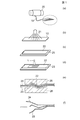
図1は、本実施形態の摺動接点の製造方法を示す工程図である。なお、各図は模式図であるが、(e)(f)は断面図として斜線を付した。
図1(a)の工程では、例えば1000~10000本の炭素繊維が束となった炭素繊維束10がボビン20に巻回されている。なお、図1(a)に示す丸で囲った部分は炭素繊維束10を拡大して示したものである。炭素繊維束10は、多数本の炭素繊維がサイジング材にて軽接着されたものである。
次に図1(b)の工程では、炭素繊維束10の表面に熱硬化性樹脂の溶液21を含浸させる。例えば、熱硬化性樹脂の溶液21を噴霧したり、溶液中に炭素繊維束10を浸漬する方法がある。図1(b)は、熱硬化性樹脂の溶液21を、噴霧している図である。
本実施形態では、図1(b)の工程では、熱硬化性樹脂として、トリフェニルグリシジルエーテルメタン(Tri-PGEM)、クレゾールノボラックエポキシ、テトラグリシジルジアミノフェニルメタン(Tet-GDDM)、テトラフェニルグリシジルエーテルエタン(Tet-PGEE)のうち少なくともいずれか1種と、硬化剤としてジアミノジフェニルスルフォン(DDS)、酸無水物、ジシアンジアミド(DICY)のうち少なくともいずれか1種とを用いることが好適である。特に、トリフェリルグリシジルエーテルメタン(Tri-PGEM)に、潜在型硬化剤としてジアミノジフェニルスルフォン(DDS)を例えば、カビトールアセテート中に分散させた溶液21を用いることが好ましい。
続いて、乾燥工程により、溶剤を除去する。
上記により、炭素繊維束10に未硬化の熱硬化性樹脂を含浸させた平板状のプリプレグ22を成形できる。
上記により、炭素繊維束10に未硬化の熱硬化性樹脂を含浸させた平板状のプリプレグ22を成形できる。
次に図1(c)の工程では、プリプレグ22を離型シート23上に載置する。この離型シート23は離型性のほかに透明で耐熱性に優れていることが好ましく、具体的にはフッ素樹脂フィルム(例えば旭硝子株式会社のアフレックス(登録商標))が良い。また、図1(c)では、離型シート23を、プリプレグ22の両面に配置することもできるが、図1(c)の工程では、離型シート23を少なくともプリプレグ22の片面に配置すればよい。
次に図1(d)の工程では、例えばYAGレーザを用いて、プリプレグ22を所定形状に切り出す。YAGレーザは特に、FAYbと呼ばれる、イッテリビウムによってレーザを増幅させる方式によるものであることが好ましい。YAGレーザの波長は例えば1024nm程度である。このとき、図1(d)のようにプリプレグ22の露出表面側(離型シート23を配置した面に対して反対面側)からレーザLを照射する。本実施形態では離型シート23に透明シートを用いたので、レーザLが離型シート23を透過して、離型シート23は切断されず、プリプレグ22のみを切断できる。なお、図1(c)の工程で、プリプレグ22の両面に離型シート23を配置した場合、レーザLは、プリプレグ22に到達する前に一方の離型シート23内を透過するが、離型シート23内でのレーザLの拡散により、プリプレグ22を所定形状に精度良く切り出せない場合があるので、図1(c)の工程で、プリプレグ22の両面に離型シート23を配置したときは、図1(d)のレーザ加工工程で、一旦、一方の離型シート23を取り外すことが必要である。
次に図1(e)の工程では、プリプレグ22の両面に離型シート23,24を配置する。このとき、既に、プリプレグ22の片面には離型シート23が設けられているので、もう一方の面に、離型シート24を配置する。このとき、新たに追加された離型シート24は、離型シート23のように透明であることは必要ないが、離型シート23と同じ材質としたほうがシート特性を同じにできて好適である。
そして、プリプレグ22の両面に離型シート23,24を配置した状態で、図1(e)に示すように、熱プレス機26にて熱プレスする。このとき、未硬化の熱硬化性樹脂が硬化する。しかも熱プレスにて図1(e)に示すように、プリプレグ22を立体成形でき、このとき全体を略一定厚で薄い扁平型にできる。熱処理温度を数百度(100℃~250℃)程度、熱処理時間を数十分~数時間(10分~90分)程度とする。
そして本実施形態では、プリプレグ22と熱プレス機26の間に離型シート23,24が介在することで、未硬化の熱硬化性樹脂が熱プレス機26に当接せず、樹脂層11(図9参照)が熱プレス機26側に付着してしまう等の問題が生じない。したがって、プリプレグ22に対して、熱プレスを適切に行うことができ、所定形状に適切且つ容易に立体成形することが可能である。
そして図1(f)の工程では、離型シート23,24を剥離する。
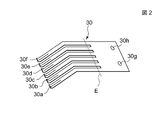
図2は図1に示す製造方法にて形成された摺動接点30の一例である。図2に示すように摺動接点30には、複数の摺動端30a~30fが形成されている。また各摺動端30a~30fは安定した電気特性を得るために例えば二股に形成されている。
図2は図1に示す製造方法にて形成された摺動接点30の一例である。図2に示すように摺動接点30には、複数の摺動端30a~30fが形成されている。また各摺動端30a~30fは安定した電気特性を得るために例えば二股に形成されている。
図2に示す摺動接点30を、一つの摺動接点として用いることもできるし、例えば、図2に示す点線Eに沿って切断すれば、複数本の摺動接点を得ることも出来る。図2の点線Eに沿って切断して得られた摺動接点1が図7に示すものである。
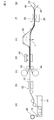
本実施形態では、図1(a)~図1(f)の一連の工程をライン化することが可能である。図3には、摺動接点の製造工程をライン化した一例が示されている。
図3(a)工程では、ボビン20に巻回された炭素繊維束10を引き出して、熱硬化性樹脂を溶剤に溶かした樹脂溶液41に浸漬する工程である。続いて図3(b)工程では、熱風ドライヤー42が用意されており、樹脂が含浸された炭素繊維束10を乾燥してプリプレグ22を形成する。次に(c)工程では、プリプレグ22の両面にキャリアテープ48,49が供給される。このキャリアテープ48,49は図1(c)~(f)に示す離型シート23,24と同様に、透明で耐熱性、離型性の高い例えばフッ素系フィルムであることが好ましい。続いて図3(d)工程では位置決めプレス機45が用意されており、キャリアテープ付きプリプレグ22に、位置決め孔を設ける。この工程により形成された位置決め孔が図2の符号30g,30hに示される。この位置決め孔30g,30hは、次工程のレーザカットの位置や熱プレス機に対する位置を制御するためのものである。続いて図3(e)工程では、一旦、プリプレグ22の上面側に配置されたキャリアテープ49を剥離した状態にして、プリプレグ22の露出表面に対してレーザ照射機46によりレーザ加工を施して摺動接点の外形を画定する。このとき、プリプレグ22の下面側のキャリアテープ48は透明でありレーザを透過するので切断されず、そのままプリプレグ22を搬送するのに用いることが出来る。次に、図3(e)工程と図3(f)工程の間に、プリプレグ22の上面にキャリアテープ49を供給する。図3(c)工程では、プリプレグ22の両面にキャリアテープ48,49を配置したが、プリプレグ22の片方のキャリアテープ49については、図3(e)工程と図3(f)工程の間で初めて供給されるようにすることも出来る。プリプレグ22の両面にキャリアテープ48,49を配置した状態で図3(f)工程の熱プレス機26による成形工程に搬送する。図3(f)工程では、プリプレグ22に対して熱プレスを施すことで、未硬化の熱硬化性樹脂の加熱硬化と、圧縮による立体成形を施す。このとき、プリプレグ22の両面にキャリアテープ48,49が配置されており、またこのキャリアテープ48,49は耐熱性が高いことから、熱プレス工程でもキャリアテープ48,49が溶けたりせず、熱プレス工程時に、プリプレグ22と熱プレス機26との間に適切にキャリアテープ48,49を介在させておくことができる。そして、図3(g)工程では、キャリアテープ48、49を、立体成形された摺動接点の両面から取り外す。このとき、キャリアテープ48,49は離型性が高いので、簡単且つ適切にキャリアテープ48,49を摺動接点の両面から取り外すことが可能である。
上記した本実施形態の摺動接点の製造方法では、炭素繊維束10に樹脂を含浸したプリプレグ22の両面に離型シート23,24(図3では、キャリアテープ48,49)を配置した状態で熱プレスする(図1(e)工程、図3(f)工程)点に特徴的部分がある。これにより、プリプレグ22と熱プレス機26の間に離型シート23,24(図3では、キャリアテープ48,49)が介在するのでプリプレグ22に対して熱プレスを適切に行うことができ、従来に比べて生産性良く簡単且つ安定して所定形状に成形できる。
また図3で示した本実施形態においては、樹脂として、熱硬化性樹脂を用いた場合について説明した。熱硬化性樹脂を用いることで、熱プレスにより、樹脂の加熱硬化とともに圧縮によって成形加工を同時に行なうことが可能である。また高いガラス転移点Tgのものを得ることができるため、摺動接点の耐熱性を向上させることができる。
なお、炭素繊維束10に含浸させる樹脂は、熱硬化性樹脂に限定されず、熱可塑性樹脂であってもよい。樹脂として、熱可塑性樹脂を用いる場合には、図3(a)工程の樹脂溶液41に代えて、熱可塑性樹脂を加熱することにより液状とした溶融樹脂とすればよく、図3(b)工程の熱風ドライヤー42による乾燥工程を省くことが出来る。また図3(f)工程の熱プレス機26による成形工程は、炭素繊維束10に熱可塑性樹脂を含浸させてなるプリプレグにおける樹脂(熱可塑性樹脂)を加熱変形させる工程となることから、短時間で熱プレスによる成形加工を行うことができる。なお、熱可塑性樹脂としては、ポリアミド樹脂、PPS樹脂、PBT樹脂等を例示することが出来る。
また本実施形態では、プリプレグ22にレーザ照射して所定の接点形状に切断した後、熱プレスを行うことが好ましい(図1(d)(e)、図3(e)(f))。これにより、平板状のプリプレグ22に簡単且つ適切にレーザ照射により接点形状を画定でき、またレーザ照射により適切にプリプレグ22を切断できる。そして、接点の平面形状を画定した後、プリプレグ22を熱プレスすることで、外形が画定された摺動接点を適切に立体成形することが可能である。
また図3に示すように、プリプレグ22を帯状体で形成した後、プリプレグ22を透明のキャリアテープ48上に配置してレーザ加工工程へ搬送し、次に、プリプレグ22の両面にキャリアテープ48,49を配置した状態にして熱プレスの成形工程へ搬送することが可能である。本実施形態では、レーザ加工工程では、透明なキャリテープ48は切断されないので、所定形状に切断されたプリプレグ22を熱プレス工程まで適切に搬送できる。このようにキャリアテープ48をレーザ加工工程のプリプレグ22に対する基台として用いることができ、別途、前記基台を用意することなくレーザ加工を行うことが出来る。また、熱プレス工程前に、レーザ加工されたプリプレグ22の両面に離型性のキャリアテープ48,49を配置することで、熱プレスを適切に行うことができ、このように一連の工程を、プリプレグ22をキャリアテープ48,49により搬送させて行うことでライン化することが出来る。
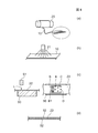
図4,図5は、別の実施形態における摺動接点の製造方法を示す工程図である。
まず図4(a)の工程に示すボビン20に巻回された炭素繊維束10を引き出して、図4(b)に示すように、炭素繊維束10の表面に熱硬化性樹脂の溶液21を含浸させる。続いて、乾燥工程により、溶剤を除去する。
まず図4(a)の工程に示すボビン20に巻回された炭素繊維束10を引き出して、図4(b)に示すように、炭素繊維束10の表面に熱硬化性樹脂の溶液21を含浸させる。続いて、乾燥工程により、溶剤を除去する。
上記により、炭素繊維束10に未硬化の熱硬化性樹脂を含浸させた平板状のプリプレグ22を帯状体で成形できる。
次に、帯状体のプリプレグ22を搬送し、図4(c)の左図(部分断面図)に示すように、ガラス板50上に配置する。図4(c)の右図は部分平面図を示している。
図4(c)の工程では、レーザ照射機51からレーザLを照射して、プリプレグ22を摺動接点の形状に切り出す。レーザLは図1(d)工程で説明したと同様に、YAGレーザであることが好適である。このとき、図4(c)に示すようにプリプレグ22の露出表面側(ガラス板50を配置した面に対して反対面側)にレーザLを照射する。
この工程では、図4(c)の右図に示すように、プリプレグ22をレーザ加工により摺動接点の形状Aに切断する。図4(c)の右図に示すように、摺動接点の形状Aは、接点部Bと接点部B以外の非接点部Cとで画定される。ここで接点部Bには少なくとも図2に示す摺動端30a~30fの外形を画定する接点部B1を含み、好ましくは図2に示す点線Eよりも図示左側(点線Eに沿って切断して残される側)における摺動接点の外形全体を指す。よって、非接点部Cとは、図2に示す点線Eよりも図示右側(点線Eに沿って切断して除去される側)の外形であることが好適である。
図4(c)の右図に示すように、プリプレグ22に、帯状体との連結箇所Dを残した状態で、摺動接点の形状Aに切断する。このとき、図4(c)の右図に示すように、連結箇所Dを接点部B以外の部分(非接点部C)に残すことが好ましい。特に図4(c)に示すように、連結箇所Dを摺動端30a~30fの外形を画定する接点部B1と反対側の位置に設けて、接点部B1から連結箇所Dを遠ざけることがより好適である。
次に、図4(d)の工程(部分断面図;図4(c)の右図の幅方向の中心位置を厚さ方向に沿って切断した部分断面図)では、プリプレグ22の両面に離型性のキャリアテープ52,52を配置して熱プレス工程へ搬送する。
次に、図5(a)に示す工程では、キャリアテープ付きプリプレグ22を熱プレス機56にて熱プレスし、プリプレグ22を立体成形する。このとき、未硬化の熱硬化性樹脂が硬化して、プリプレグ22の成形体が得られる。
続いて図5(b)の工程では、キャリアテープ付きの硬化したプリプレグ22(プリプレグ22の成形体)をボビン(リール)53に巻き取る。本実施形態では、摺動接点が連結された帯状体のプリプレグ22の成形体を両面にキャリアテープ52,52を配置した状態で保管でき、摺動接点の使用直前まで、摺動接点を適切に保護することが出来る。よって、摺動接点が機械的損傷(曲げや破損等)や汚染等の不具合を生じにくい。また、ハンドリング性の向上を図ることができる。
キャリアテープ付きプリプレグ22の成形体より摺動接点を切り出すには、ボビン53に巻かれたキャリアテープ付きプリプレグ22の成形体を引き出して、図5(c)に示すように、プリプレグ22の成形体の片面に配置されたキャリアテープ52を剥がし、レーザ照射機58を用いて連結箇所DをレーザLにより切断する。レーザLには図4(c)工程と同様にYAGレーザを用いることが好適である。これにより連結箇所Dを金型等で切断する場合に比べて摺動接点へのダメージを小さくでき、摺動接点の生産性を向上させることができる。図5(c)工程でのレーザ照射機58と図4(c)工程でのレーザ照射機51とは同じものであってもよいし別のものであってもよい。このように摺動接点の使用直前まで、摺動接点をキャリアテープ付きプリプレグ22の成形体の状態にてボビン53に巻き取った状態で保護でき、摺動接点の使用の際に、必要な数の摺動接点だけをキャリアテープ付きプリプレグ22の成形体から切り離すことができる。よって本実施形態では、各摺動接点をばらばらの状態で保管することなく、摺動接点を適切に保護することができるとともに、摺動接点のハンドリング性を向上させることができる。なお図5(b)(c)において、プリプレグ22の成形体にも便宜上、符号22を付している。
図6は、図4,図5の一連の工程をライン化した一例である。
図6(a)工程では、ボビン(リール)20に巻かれた状態の炭素繊維束10を引き出して、熱硬化性樹脂を溶剤に溶かした樹脂溶液41に浸漬する工程である。続いて図6(b)工程では、熱風ドライヤー42が用意されており、樹脂が含浸された炭素繊維束10を乾燥してプリプレグ22を帯状体で形成する。次に図6(c)工程では、プリプレグ22を搬送してガラス板50上に配置し、プリプレグ22に対しレーザ照射機51によりレーザLを照射してプリプレグ22を所定の摺動接点の形状に切断する。このとき図6(d)に示すように、プリプレグ22に帯状体との連結箇所Dを残した状態で、摺動接点の形状Aに切断する。このとき、連結箇所Dを、非接点部C側に残すことが好ましい。また連結箇所Dを摺動端30a~30fの外形を画定する接点部B1と反対側の位置に残すことがより好適である。
図6(a)工程では、ボビン(リール)20に巻かれた状態の炭素繊維束10を引き出して、熱硬化性樹脂を溶剤に溶かした樹脂溶液41に浸漬する工程である。続いて図6(b)工程では、熱風ドライヤー42が用意されており、樹脂が含浸された炭素繊維束10を乾燥してプリプレグ22を帯状体で形成する。次に図6(c)工程では、プリプレグ22を搬送してガラス板50上に配置し、プリプレグ22に対しレーザ照射機51によりレーザLを照射してプリプレグ22を所定の摺動接点の形状に切断する。このとき図6(d)に示すように、プリプレグ22に帯状体との連結箇所Dを残した状態で、摺動接点の形状Aに切断する。このとき、連結箇所Dを、非接点部C側に残すことが好ましい。また連結箇所Dを摺動端30a~30fの外形を画定する接点部B1と反対側の位置に残すことがより好適である。
更に、図6(c)のレーザ加工工程では図6(d)に示すように、位置決め孔55,55をレーザ加工することができる。
次に図6(e)の工程では、プリプレグ22の両面にキャリアテープ52を供給する。このキャリアテープ52は耐熱性、離型性の高い例えばフッ素系フィルムであることが好ましい。またキャリアテープ52は透明であってもよいし半透明、不透明であってもよい。ただし透明であることがハンドリング性等を向上させることができ好適である。
続いて図6(f)工程では、キャリアテープ付きプリプレグ22を熱プレス機56による成形工程に搬送する。熱プレス機56には位置決め突起部57が設けられており、図6(d)に示すプリプレグ22に形成された位置決め孔55を熱プレス機56の位置決め突起部57に挿入してプリプレグ22の熱プレス機56に対する位置決めを行う。
また、図6(c)のレーザ加工工程で位置決め孔55を形成せず、熱プレス機56に設けられた位置決め突起部57の先端を先鋭にしておき、位置決め突起部57にて、キャリアテープ付きプリプレグ22に孔を形成してもよい。本実施形態では、熱プレス工程にてキャリアテープ付きプリプレグ22と熱プレス機56間の位置決めを高精度に行うことが可能である。なお図3(f)の熱プレス機26には位置決め突起部を図示していないが図3(f)の熱プレス機26にも位置決め突起部が設けられている。
図6(f)工程では、プリプレグ22に対して熱プレスを施すことで、未硬化の熱硬化性樹脂の加熱硬化と、圧縮による立体成形を施す。このとき、プリプレグ22の両面にキャリアテープ52が配置されており、またこのキャリアテープ52は耐熱性が高いことから、熱プレス工程でもキャリアテープ52が溶けたりせず、熱プレス工程時に、プリプレグ22と熱プレス機56との間に適切にキャリアテープ52を介在させておくことができる。そして、図6(g)工程では、キャリアテープ付きプリプレグ22の成形体をボビン53に巻き取る。
そして、摺動接点の使用時に、図5(c)で説明したように、キャリアテープ付きプリプレグ22の成形体をボビン53から引き出して、片面のキャリアテープ52を剥がし、プリプレグ22の成形体に形成された帯状体との連結箇所DをレーザLにて切断することで、摺動接点を取り出すことができる。
図4ないし図6に示す実施形態の摺動接点の製造方法でも、図1,図3と同様に、プリプレグ22の両面に離型性のキャリアテープ52,52を配置した状態で熱プレスする(図5(a)の工程、図6(f)の工程)。これにより、プリプレグ22と熱プレス機56の間にキャリアテープ52,52が介在するのでプリプレグ22に対して熱プレスを適切に行うことができ、従来に比べて生産性良く簡単且つ安定して所定形状に成形できる。
また図6における実施形態は、樹脂として、熱硬化性樹脂を用いたものである。熱硬化性樹脂を用いることで、熱プレスにより、樹脂の加熱硬化とともに圧縮による成形加工を同時に行なうことが可能である。また、ガラス転移温度Tgを高めることができるので、摺動接点の耐熱性を向上させることもできる。
なお、炭素繊維束10に含浸させる樹脂は、熱硬化性樹脂に限定されず、熱可塑性樹脂であってもよい。樹脂として、熱可塑性樹脂を用いる場合には、図6(a)工程の樹脂溶液41に代えて、熱可塑性樹脂を加熱することにより液状とした溶融樹脂とすればよく、図6(b)工程の熱風ドライヤー42による乾燥工程を省くことが出来る。また図6(f)工程の熱プレス機56による成形工程は、炭素繊維束10に熱可塑性樹脂を含浸させてなるプリプレグにおける樹脂(熱可塑性樹脂)を加熱変形させる工程となることから、短時間で熱プレスによる成形加工を行うことができる。なお、熱可塑性樹脂としては、ポリアミド樹脂、PPS樹脂、PBT樹脂等を例示することが出来る。
図4(c)工程、及び、図6(c)工程に示すように、プリプレグ22をガラス板50に配置してレーザ加工を行っている。これにより、レーザ照射を行ってもガラス板(基台)50が変形せず、プリプレグ22を安定してガラス板50に支持でき、プリプレグ22に対しレーザ加工をより高精度に行うことが可能である。
また、図4(c)工程、及び、図6(c)(d)工程に示すように、レーザ加工工程にて、プリプレグ22に帯状体との連結箇所Dを残した状態で、摺動接点の形状Aに切断している。これにより、摺動接点が連結した帯状体のプリプレグ22の成形体を両面にキャリアテープ52,52を配置した状態で保管でき、使用直前まで、摺動接点を適切に保護することが出来る。よって、摺動接点が機械的損傷(曲げや破損等)や汚染等の不具合を生じにくい。また、摺動接点のハンドリング性の向上を図ることができる。
また図4(c)工程、及び、図6(c)(d)工程に示すように、連結箇所Dを接点部B以外の部分(非接点部C)に残すことが好ましい。図5(c)に示すように、連結箇所Dを切断して摺動接点を帯状体から切り離す際に、接点部Bが切り離しの際のダメージを受けず、安定した品質の摺動接点を製造することができる。
上記した各製造方法により形成された図7に示す摺動接点1は、支持端2から弾性変形可能に延出し、その先端が摺動端3として立体成形された構成である。
例えば図7に示す摺動接点1は、図8のように、支持基板4に支持固定されている。摺動接点1は屈曲部5から傾斜した立体形状である。そして屈曲部5から摺動端3までの間が主に弾性変形可能な領域として機能している。また図7の構成では、摺動端3を折り曲げているが、折り曲げなくてもよい。
図8に示すように、支持基板4には、摺動接点1の支持端2に当接する金属端子6が設けられている。金属端子6は全体が金属で形成され、例えばプレスにて切断加工されている。金属端子6の一端は摺動接点1の支持端2に当接する当接部6aであり、他端が、外部に引き出されて外部接続部に電気的に接続される外部接続端6bである。
図8に示す実施形態では支持基板4には、凹部7が設けられ、凹部7の対向する側壁面7a,7bのうち、一方の側壁面7aに摺動接点1の支持端2と金属端子6の当接部6aとが当接して配置されている。そして、支持基板4に形成された凹部7内に固定部材8が圧入され、支持端2と当接部6aとが密着している。固定部材8は弾性部材であることが好ましく、これにより図8のように固定部材8を凹部7内に圧入することで当接部6aを支持端2方向へ押圧できる。このとき、当接部6aと支持端2間を適切に電気的に接続できるように、支持端2の表面には炭素繊維束10が露出していることが好ましい。
図9に示すように、本実施形態の摺動接点1は、図7に示す支持端2から摺動端3の全体が、支持端2から摺動端3に延在する炭素繊維束10と、炭素繊維束10に含浸されてなる樹脂層11とを有して略一定厚で成形されている。摺動接点1は、10~500μm程度の厚みで形成されている。
本実施形態では、一方の端部の支持端2から弾性変形可能に延出し、その先端の摺動端3にかけて、炭素繊維束10と、炭素繊維束10に含浸されてなる樹脂層11とを備えた略一定厚の立体構造であり、これにより、ばね性に優れ、安定した電気特性を示す摺動接点1に出来る。そして本実施形態では、例えば、摺動接点1の摺動端3と、可変抵抗器の抵抗基板やエンコーダのコード板との間に潤滑性を向上させるためにオイル等を介在させなくても磨耗しにくい構造に出来る。
本実施形態では、前述したように、熱プレスにより熱硬化性樹脂を硬化させ、あるいは、熱可塑性樹脂を加熱変形させ、且つ圧縮により略一定厚の薄い扁平型にて立体成形しやすい。またプリプレグの状態にて、支持端2から摺動端3にかけての延出方向の側面及び摺動端3の摺動面3aがレーザ加工されたものであるから、摺動接点1の切断外形をレーザにて適切に画定でき、また図9に示すように、摺動端3の摺動面3aに炭素繊維束10の先端を樹脂層11とともに適切に露出させることができ、安定した電気特性を得ることが出来る。
本実施形態の摺動接点1は可変抵抗器用やエンコーダ用等として用いることが出来る。
本実施形態の摺動接点1は可変抵抗器用やエンコーダ用等として用いることが出来る。
A 摺動接点の形状
B、B1 接点部
C 非接点部
D 連結箇所
1、30 摺動接点
2 支持端
3、30a~30f 摺動端
4 支持基板
5 屈曲部
6 金属端子
6a 当接部
6b 外部接続端
8 固定部材
10 炭素繊維束
11 樹脂層
20、53 ボビン
21 熱硬化性樹脂を含む溶液
22 プリプレグ
23、24 離型シート
26、56 熱プレス機
30h、30g 位置決め孔
48、49、52 キャリアテープ
50 ガラス板
46、51、58 レーザ照射機
B、B1 接点部
C 非接点部
D 連結箇所
1、30 摺動接点
2 支持端
3、30a~30f 摺動端
4 支持基板
5 屈曲部
6 金属端子
6a 当接部
6b 外部接続端
8 固定部材
10 炭素繊維束
11 樹脂層
20、53 ボビン
21 熱硬化性樹脂を含む溶液
22 プリプレグ
23、24 離型シート
26、56 熱プレス機
30h、30g 位置決め孔
48、49、52 キャリアテープ
50 ガラス板
46、51、58 レーザ照射機
Claims (11)
- 炭素繊維束に樹脂を含浸させてプリプレグを形成するプリプレグ形成工程と、
前記プリプレグの両面に離型シートを配置した状態で熱プレスする成形工程と、
を有することを特徴とする摺動接点の製造方法。 - 前記プリプレグにレーザ照射して所定の接点形状に切断するレーザ加工工程後、前記熱プレスを行う請求項1記載の摺動接点の製造方法。
- 前記プリプレグの一方の面を透明な基台に配置した状態で、前記プリプレグの他方の面に対して前記レーザ加工工程を行い、その後、前記プリプレグの両面に前記離型シートを配置して前記熱プレスを行う請求項2記載の摺動接点の製造方法。
- 前記基台は、ガラスである請求項3記載の摺動接点の製造方法。
- 前記基台は、前記熱プレスの成形工程前に前記プリプレグの両面に配置される前記離型シートの一方からなる請求項3記載の摺動接点の製造方法。
- 前記離型シートはキャリアテープであり、前記プリプレグを帯状体に形成した後、前記プリプレグの両面に前記キャリアテープを供給し、前記キャリアテープに挟まれた状態の前記プリプレグを搬送して前記熱プレスを施す請求項2ないし5のいずれか1項に記載の摺動接点の製造方法。
- 前記レーザ加工工程にて、前記プリプレグに前記帯状体との連結箇所を残した状態で、前記接点形状に切断する請求項6記載の摺動接点の製造方法。
- 前記レーザ加工工程にて、前記プリプレグを接点形状に画定する際、接点部以外の部分に前記連結箇所を残す請求項7記載の摺動接点の製造方法。
- 前記樹脂は、熱硬化性樹脂である請求項1ないし8のいずれか1項に記載の摺動接点の製造方法。
- 前記熱硬化性樹脂は、エポキシ樹脂である請求項9記載の摺動接点の製造方法。
- 前記熱硬化性樹脂には、トリフェニルグリシジルエーテルメタン(Tri-PGEM)、クレゾールノボラックエポキシ、テトラグリシジルジアミノフェニルメタン(Tet-GDDM)、テトラフェニルグリシジルエーテルエタン(Tet-PGEE)のうち少なくともいずれか1種と、硬化剤としてジアミノジフェニルスルフォン(DDS)、酸無水物、ジシアンジアミド(DICY)のうち少なくともいずれか1種とを用いる請求項9記載の摺動接点の製造方法。
Applications Claiming Priority (4)
| Application Number | Priority Date | Filing Date | Title |
|---|---|---|---|
| JP2009-122732 | 2009-05-21 | ||
| JP2009122732 | 2009-05-21 | ||
| JP2010-104929 | 2010-04-30 | ||
| JP2010104929 | 2010-04-30 |
Publications (1)
| Publication Number | Publication Date |
|---|---|
| WO2010134599A1 true WO2010134599A1 (ja) | 2010-11-25 |
Family
ID=43126276
Family Applications (1)
| Application Number | Title | Priority Date | Filing Date |
|---|---|---|---|
| PCT/JP2010/058634 Ceased WO2010134599A1 (ja) | 2009-05-21 | 2010-05-21 | 摺動接点の製造方法 |
Country Status (1)
| Country | Link |
|---|---|
| WO (1) | WO2010134599A1 (ja) |
Cited By (1)
| Publication number | Priority date | Publication date | Assignee | Title |
|---|---|---|---|---|
| WO2020195115A1 (ja) * | 2019-03-26 | 2020-10-01 | 三菱重工業株式会社 | プリプレグ成形方法 |
Citations (3)
| Publication number | Priority date | Publication date | Assignee | Title |
|---|---|---|---|---|
| JPH0361509A (ja) * | 1989-07-31 | 1991-03-18 | Tonen Corp | 繊維強化複合樹脂シート及びその製造方 |
| WO2007142160A1 (ja) * | 2006-06-02 | 2007-12-13 | Hokuriku Electric Industry Co., Ltd. | 可変抵抗器 |
| WO2008133015A1 (ja) * | 2007-04-25 | 2008-11-06 | Alps Electric Co., Ltd. | 摺動接点 |
-
2010
- 2010-05-21 WO PCT/JP2010/058634 patent/WO2010134599A1/ja not_active Ceased
Patent Citations (3)
| Publication number | Priority date | Publication date | Assignee | Title |
|---|---|---|---|---|
| JPH0361509A (ja) * | 1989-07-31 | 1991-03-18 | Tonen Corp | 繊維強化複合樹脂シート及びその製造方 |
| WO2007142160A1 (ja) * | 2006-06-02 | 2007-12-13 | Hokuriku Electric Industry Co., Ltd. | 可変抵抗器 |
| WO2008133015A1 (ja) * | 2007-04-25 | 2008-11-06 | Alps Electric Co., Ltd. | 摺動接点 |
Cited By (3)
| Publication number | Priority date | Publication date | Assignee | Title |
|---|---|---|---|---|
| WO2020195115A1 (ja) * | 2019-03-26 | 2020-10-01 | 三菱重工業株式会社 | プリプレグ成形方法 |
| JP2020157582A (ja) * | 2019-03-26 | 2020-10-01 | 三菱重工業株式会社 | プリプレグ成形方法 |
| JP7175820B2 (ja) | 2019-03-26 | 2022-11-21 | 三菱重工業株式会社 | プリプレグ成形方法 |
Similar Documents
| Publication | Publication Date | Title |
|---|---|---|
| US10926448B2 (en) | Method for producing resin molded body and press molding apparatus | |
| CN107623981B (zh) | 柔性印刷线路板及其制造方法 | |
| US9688014B2 (en) | Transferring system and transferring method | |
| JP6163934B2 (ja) | 燃料電池のセパレータの製造方法 | |
| CN103890863B (zh) | 线束及线束的制造方法 | |
| JP2015174247A (ja) | 複合構造体及びその製造方法 | |
| KR20170090157A (ko) | 이차전지용 파우치필름을 제조하기 위한 복합 라미네이션 장치 | |
| WO2010134599A1 (ja) | 摺動接点の製造方法 | |
| JP2016162648A (ja) | 燃料電池単セルの製造方法 | |
| KR100635401B1 (ko) | 광학 반도체 장치 제조 방법 | |
| CN109699131B (zh) | 制造多层基板的方法 | |
| US20220126531A1 (en) | Automated fiber placement roller | |
| CN110114200A (zh) | 嵌入用薄膜的树脂层的厚度确定方法、带嵌入用薄膜的树脂成型品的制造方法及嵌入用薄膜 | |
| CN104425391A (zh) | 半导体装置及其制造方法 | |
| KR101950899B1 (ko) | 전자부품의 제조 방법 | |
| JP2001013334A (ja) | ファイバ型検出素子、その製造方法および製造装置、並びにそれを用いたセンサ | |
| WO2010134598A1 (ja) | 摺動接点 | |
| CN111465999B (zh) | 电阻器的制造方法 | |
| JPH1075040A (ja) | 樹脂被覆回路基板の製造方法 | |
| JP7547742B2 (ja) | 繊維強化基材の製造方法、繊維強化基材およびシャッター羽根の製造方法 | |
| JP5106320B2 (ja) | 配線基板の製造方法 | |
| WO2016086404A1 (en) | Flat cable | |
| CN104979673A (zh) | 电子部件 | |
| CN103258605A (zh) | 电气绝缘装置和用于制造电气绝缘装置的方法 | |
| KR102082540B1 (ko) | 프리폼의 제조 방법 및 제조 장치 |
Legal Events
| Date | Code | Title | Description |
|---|---|---|---|
| 121 | Ep: the epo has been informed by wipo that ep was designated in this application |
Ref document number: 10777831 Country of ref document: EP Kind code of ref document: A1 |
|
| NENP | Non-entry into the national phase |
Ref country code: DE |
|
| 122 | Ep: pct application non-entry in european phase |
Ref document number: 10777831 Country of ref document: EP Kind code of ref document: A1 |
|
| NENP | Non-entry into the national phase |
Ref country code: JP |