WO2010131610A1 - ガラス端面研削用砥石の加工位置設定方法 - Google Patents
ガラス端面研削用砥石の加工位置設定方法 Download PDFInfo
- Publication number
- WO2010131610A1 WO2010131610A1 PCT/JP2010/057837 JP2010057837W WO2010131610A1 WO 2010131610 A1 WO2010131610 A1 WO 2010131610A1 JP 2010057837 W JP2010057837 W JP 2010057837W WO 2010131610 A1 WO2010131610 A1 WO 2010131610A1
- Authority
- WO
- WIPO (PCT)
- Prior art keywords
- grindstone
- glass
- glass plate
- grinding
- processing position
- Prior art date
- Legal status (The legal status is an assumption and is not a legal conclusion. Google has not performed a legal analysis and makes no representation as to the accuracy of the status listed.)
- Ceased
Links
Images


Classifications
-
- B—PERFORMING OPERATIONS; TRANSPORTING
- B24—GRINDING; POLISHING
- B24B—MACHINES, DEVICES, OR PROCESSES FOR GRINDING OR POLISHING; DRESSING OR CONDITIONING OF ABRADING SURFACES; FEEDING OF GRINDING, POLISHING, OR LAPPING AGENTS
- B24B1/00—Processes of grinding or polishing; Use of auxiliary equipment in connection with such processes
-
- B—PERFORMING OPERATIONS; TRANSPORTING
- B24—GRINDING; POLISHING
- B24B—MACHINES, DEVICES, OR PROCESSES FOR GRINDING OR POLISHING; DRESSING OR CONDITIONING OF ABRADING SURFACES; FEEDING OF GRINDING, POLISHING, OR LAPPING AGENTS
- B24B47/00—Drives or gearings; Equipment therefor
- B24B47/22—Equipment for exact control of the position of the grinding tool or work at the start of the grinding operation
-
- B—PERFORMING OPERATIONS; TRANSPORTING
- B24—GRINDING; POLISHING
- B24B—MACHINES, DEVICES, OR PROCESSES FOR GRINDING OR POLISHING; DRESSING OR CONDITIONING OF ABRADING SURFACES; FEEDING OF GRINDING, POLISHING, OR LAPPING AGENTS
- B24B49/00—Measuring or gauging equipment for controlling the feed movement of the grinding tool or work; Arrangements of indicating or measuring equipment, e.g. for indicating the start of the grinding operation
- B24B49/16—Measuring or gauging equipment for controlling the feed movement of the grinding tool or work; Arrangements of indicating or measuring equipment, e.g. for indicating the start of the grinding operation taking regard of the load
-
- B—PERFORMING OPERATIONS; TRANSPORTING
- B24—GRINDING; POLISHING
- B24B—MACHINES, DEVICES, OR PROCESSES FOR GRINDING OR POLISHING; DRESSING OR CONDITIONING OF ABRADING SURFACES; FEEDING OF GRINDING, POLISHING, OR LAPPING AGENTS
- B24B9/00—Machines or devices designed for grinding edges or bevels on work or for removing burrs; Accessories therefor
- B24B9/02—Machines or devices designed for grinding edges or bevels on work or for removing burrs; Accessories therefor characterised by a special design with respect to properties of materials specific to articles to be ground
- B24B9/06—Machines or devices designed for grinding edges or bevels on work or for removing burrs; Accessories therefor characterised by a special design with respect to properties of materials specific to articles to be ground of non-metallic inorganic material, e.g. stone, ceramics, porcelain
- B24B9/08—Machines or devices designed for grinding edges or bevels on work or for removing burrs; Accessories therefor characterised by a special design with respect to properties of materials specific to articles to be ground of non-metallic inorganic material, e.g. stone, ceramics, porcelain of glass
- B24B9/10—Machines or devices designed for grinding edges or bevels on work or for removing burrs; Accessories therefor characterised by a special design with respect to properties of materials specific to articles to be ground of non-metallic inorganic material, e.g. stone, ceramics, porcelain of glass of plate glass
Definitions
- the present invention relates to a method for setting a processing position of a grindstone for grinding a glass end face, and particularly when chamfering or mirror-finishing an end face of an FPD (Flat Panel Display) glass substrate such as a liquid crystal display glass substrate or a plasma display glass substrate.
- the present invention relates to a processing position setting method for a glass end surface grinding grind performed to set a processing position of a grindstone.
- the end surface of the actual glass substrate is generally replaced after the grindstone is replaced
- the processing position of the grindstone was manually set by inputting the correction value in the Y-axis direction several times after confirming the processing condition of the end face.
- the processing position refers to the position of the grindstone when starting to move the grindstone used for processing in a direction parallel to the side of the rectangular glass substrate (X-axis direction).
- the Y axis refers to an axis that moves the grindstone toward the end surface of the glass substrate, that is, an axis that is orthogonal to the side of the rectangular glass substrate.
- the grindstone may be moved in the Y-axis direction to the set processing position, and then the grindstone may be moved in the X-axis direction to mirror the end surface of the glass substrate.
- the unevenness of the end surface caused by the chamfering process before the mirror surface processing is ground by the mirror surface processing.
- a servo motor capable of position control and a ball screw driven by this servo motor are generally used.
- a method for automatically setting the processing position of the grindstone in the Y-axis direction is also known.
- the grindstone is moved in the Y-axis direction by the servo motor while the grindstone is rotated by the grindstone rotating motor (inverter motor), and the load fluctuation of the current value of the grindstone rotating motor exceeds a predetermined threshold value.
- the processing position in the Y-axis direction is set by determining that the grindstone is in contact with the end surface of the glass substrate.
- Patent Document 1 discloses a glass substrate that measures the height position of a suction stage on which a liquid crystal display panel to be chamfered is mounted with a laser displacement meter and automatically adjusts the height position of a grindstone based on the height position information.
- a chamfering apparatus is disclosed. That is, in the chamfering device of Patent Document 1, when the height position information of the suction stage measured by the laser displacement meter is output to the control unit of the chamfering device, the control unit receives the conversion data that is input in advance. Is used to calculate an appropriate height of the grindstone, and the grindstone is adjusted in the vertical direction by the robot so as to obtain the height.
- the processing position adjustment of the grindstone in Patent Document 1 is to adjust the position in the height direction of the grindstone with respect to the end surface of the glass substrate, and not to adjust the processing position in the Y-axis direction described above.
- the processing position of the grinding wheel is set by changing the load of the current value of the grinding wheel rotation motor while contacting the end surface of the glass plate while rotating the grinding stone
- the rotating grinding stone contacts the end surface of the glass plate. Due to variations in grinding resistance when touching, there may be a large deviation in positional accuracy. In this case, the grindstone may move too much in the Y-axis direction. There was a risk of damage. Further, even if the damage can be prevented, the grindstone rotates at a high speed, so that there is a problem that a shaving mark that is defective in quality is generated on the glass plate.
- the present invention has been made in view of such circumstances, and can suppress variations in the processing position accuracy of the grindstone with respect to the end surface of the glass plate, and can prevent the glass plate and the grindstone from being damaged. It is an object to provide a processing position setting method for a grinding wheel for grinding a glass end face, which can improve quality and further improve productivity by using a glass plate as a product for setting a processing position. .
- the present invention sets the processing position of the grindstone with respect to the end surface of the glass plate in a processing apparatus that grinds the end surface of the glass plate by pressing a rotating grindstone against the end surface of the glass plate.
- a method for setting a processing position of a grindstone for grinding a glass end surface the rotation of the grindstone is stopped, the grindstone is moved toward the end surface of the glass plate by the power of a servo motor, and the grindstone is moved to the end surface of the glass plate.
- a processing position setting method for a grindstone for grinding a glass end surface wherein the processing position of the grindstone is set based on a fluctuation value of a load of the servo motor generated upon contact and a glass end surface grinding allowance.
- the processing point is not set by the load fluctuation of the current value of the grindstone rotating motor, but the zero point of the grindstone is based on the load fluctuation value of the servo motor that moves the grindstone toward the end surface of the glass plate. Set the position. In this case, since the grindstone does not need to be rotated, the rotation is stopped.
- the load on the servo motor slightly fluctuates due to the feed load. Then, when the grindstone comes into contact with the end face of the glass plate, the load of the servo motor greatly fluctuates immediately thereafter, and when the fluctuating load exceeds a predetermined threshold, the servo motor is stopped to stop the movement of the grindstone.
- the stop position is set as the zero point position, and the position moved from the zero point position by the grinding allowance in the Y-axis direction is set as the machining position.
- the predetermined threshold value of the load is a value exceeding the load (feed load) required for the rotation of the ball screw device by the servo motor.
- the machining position setting method of the present invention the position when the grindstone in the rotation stop state contacts the end face of the glass plate is set as the zero point position, and the position moved from the zero point position by the grinding allowance in the Y-axis direction is set. Since the processing position is set, variation in the processing position accuracy of the grindstone with respect to the end surface of the glass plate can be suppressed. Thereby, damage to the glass plate and the grindstone can be prevented, and the quality of the glass plate is improved because no shaving mark is attached to the glass plate. Therefore, since the glass plate used as a product can be used for processing position setting, without using a dummy glass plate by these effects, productivity of a glass plate improves.
- the processing position of the grindstone is set in a state in which the rotation is stopped, the processing position may be set while rotating the grindstone as long as the rotational speed does not contribute to grinding.
- the grindstone of the present invention is preferably a mirror grindstone.
- the grinding allowance with the grindstone is as large as several hundreds ⁇ m, so high precision is not required at the machining position.
- the grinding allowance is as small as several ⁇ m, so the precision at the machining position is high. Is required. Therefore, it is preferable that the processing position set by the processing position setting method of the present invention is a processing position of a grindstone for mirror surface processing.
- the glass plate of the present invention is preferably a glass substrate for FPD.
- the processing position setting method of the present invention can also be applied to an architectural glass plate, but is suitable for setting the processing position of an end surface grinding apparatus for an FPD glass plate that requires high accuracy.
- the position when the rotation stopped grindstone comes into contact with the end face of the glass plate is set as the zero point position. Since the position moved by the grinding allowance in the axial direction is set as the processing position, variation in the processing position accuracy of the grindstone with respect to the end surface of the glass plate can be suppressed, thereby preventing breakage of the glass plate and the grindstone. . In addition, since no shaving mark is attached to the glass plate, the quality of the glass plate is improved. Therefore, since the glass plate used as a product can be used for processing position setting, without using a dummy glass plate by these effects, productivity of a glass plate improves.
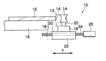
- FIG. 1 is a plan view of a glass end surface grinding apparatus 10 to which a processing position setting method for a glass end surface grinding wheel of the present invention is applied
- FIG. 2 is a side view of a main part of the glass end surface grinding apparatus 10 shown in FIG. FIG.
- This glass end surface grinding apparatus 10 is an apparatus for mirror-treating a chamfered portion processed on an end surface of an FPD glass substrate 12 that is a processing object, using a mirror surface processing grindstone 14.
- the glass end surface grinding apparatus 10 has a table 16 that sucks and holds a glass substrate 12 formed in a rectangular shape, and the glass substrate 12 is sucked and held on the table 16 with a predetermined positional accuracy.
- the grindstone 14 is detachably fixed to a rotating shaft 20 of an inverter motor 18 that is a grindstone rotating motor, and is rotated at a predetermined rotational speed by the power of the inverter motor 18.
- the grindstone 14 is moved along the side portion 13 of the glass substrate 12 in a state of being rotated by the inverter motor 18 by being moved to a processing position to be described later and being brought into contact with the end surface of the side portion 13 of the glass substrate 12. . Thereby, the end surface of the side portion 13 of the glass substrate 12 is mirror-finished.
- the inverter motor 18 is mounted on a nut portion 22, and this nut portion 22 is screwed into a ball screw 24 laid in the Y-axis direction.
- the ball screw 24 is connected to a rotation shaft (not shown) of the servo motor 26. Therefore, when the servo motor 26 is driven and the ball screw 24 is rotated, the grindstone 14 moves in the Y-axis direction with a feed accuracy of submicron order via the nut portion 22 and the inverter motor 18. Therefore, when the ball screw 24 is rotated forward / reversely by the servo motor 26, the grindstone 14 moves forward / backward with respect to the side portion 13 of the glass substrate 12.
- the nut portion 22 is screwed into a feed screw 28 laid in the X-axis direction orthogonal to the Y-axis direction, and the feed screw 28 is connected to a rotating shaft (not shown) of the motor 30. Therefore, when the motor 30 is driven to rotate the feed screw 28, the grindstone 14 moves in the X-axis direction via the nut portion 22 and the inverter motor 18. Therefore, when the feed screw 28 is rotated forward / reversely by the motor 30, the grindstone 14 reciprocates with respect to the side portion 13 of the glass substrate 12.
- the setting of the processing position of the grindstone 14, which will be described below, that is, the condition setting in the Y-axis direction of the grindstone 14 is performed each time the worn grindstone 14 is replaced with a new grindstone 14.
- the grindstone 14 is moved forward in the Y-axis direction toward the side portion 13 of the glass substrate 12, and the position at which the grindstone 14 contacts the side portion 13 of the glass substrate 12 is set as the zero point position. And stored in the control unit 32.
- the grindstone 14 is moved in the Y-axis direction by the grinding allowance from the zero point position stored in the control unit 32. Thereafter, the grindstone 14 is moved in the X-axis direction, whereby the glass substrate 12 is moved.
- the end surface of the side portion 13 is mirror-finished.
- the grindstone 14 is retracted from the side portion 13 of the glass substrate 12 in a predetermined amount in the Y-axis direction. At this time, the grindstone 14 is stopped.
- the load of the servo motor slightly fluctuates due to the feed load.
- the load on the servo motor 26 greatly fluctuates immediately thereafter, and the servo motor 26 is stopped when the fluctuating load exceeds a predetermined threshold.
- the movement of the grindstone 14 in the Y-axis direction is stopped, and the stop position is set as the zero point position and stored in the control unit 32.
- the threshold value is set to a value exceeding the load (feed load) required for rotation of the ball screw device by the servo motor.
- the position moved by the grinding allowance in the Y-axis direction from the zero point position is set as the machining position.
- the servo motor that moves the grindstone 14 toward the side portion 13 of the glass substrate 12 instead of setting the machining position by the load fluctuation of the current value of the inverter motor 18.
- the zero point position of the grindstone 14 is set based on the load fluctuation value 26, and the position moved from the zero point position by the grinding allowance in the Y-axis direction is set as the machining position.
- FIG. 3 shows a graph representing the load variation of the servo motor 26.
- the vertical axis of the graph of FIG. 3 indicates the load (%) of the servo motor 26, and the horizontal axis indicates the feed position of the grindstone 14 in the Y-axis direction.
- the normal load is determined by the rotational resistance of the ball screw 24, the feed speed of the ball screw 24, and the like, and is in the range of A to B (%) according to the graph of FIG. Therefore, the position where the grindstone 14 is in contact with the side portion 13 of the glass substrate 12 is a load (threshold value) exceeding the upper limit A (%) of the range, and is a position where the control unit 32 detects the load. That is, when the control unit 32 detects a load exceeding A (%), the control unit 32 recognizes and stores the position as a zero point position.
- the position when the grindstone 14 in the rotation stop state contacts the end surface of the side portion 13 of the glass substrate 12 is set as the zero point position, and the zero point position is changed to the Y axis direction. Since the position moved by the grinding allowance is set as the processing position, variations in the processing position accuracy of the grindstone 14 with respect to the end surface of the glass substrate 12 can be suppressed. Thereby, the glass substrate 12 and the grindstone 14 can be prevented from being damaged, and the quality of the glass substrate 12 is improved because the glass substrate 12 is not marked by the grinding stone 14.
- the glass substrate 12 as a product can be used for processing position setting without using a dummy glass substrate, so that the productivity of the glass substrate 12 is improved.
- the processing position setting method of the mirror-finishing grindstone 14 has been described.
- the present invention can also be applied to the processing position setting of the chamfering grindstone.
- the grinding allowance with the grindstone is as large as several hundreds ⁇ m, so that high accuracy is not required for the processing position.
- the grinding allowance is as small as several ⁇ , high accuracy is required for the processing position. Therefore, it is preferable that the grindstone set by the machining position setting method according to the embodiment is the grindstone 14 for mirror surface machining.
- the processing position setting method of the grindstone 14 which mirror-processes the end surface of the glass substrate 12 for FPD was demonstrated
- the glass substrate made into object is not limited to the glass substrate for FPD,
- a building Glass plates for solar cells and glass substrates for solar cells may be used.
- the processing position setting method of the embodiment is suitable for the processing position setting method of the end surface grinding apparatus for FPD glass sheets that requires high accuracy.
- the glass end surface grinding apparatus 10 that mirror-processes the side 13 of the glass substrate 12 is illustrated, but it can also be applied to a grinding apparatus that simultaneously mirrors two opposing sides of the glass substrate 12.
- the present invention can also be applied to a grinding apparatus that simultaneously mirrors the four sides of the glass substrate 12.
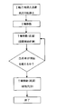
- FIG. 4 is a flowchart showing an example of the operation of the software.
Landscapes
- Engineering & Computer Science (AREA)
- Mechanical Engineering (AREA)
- Chemical & Material Sciences (AREA)
- Ceramic Engineering (AREA)
- Inorganic Chemistry (AREA)
- Grinding And Polishing Of Tertiary Curved Surfaces And Surfaces With Complex Shapes (AREA)
- Constituent Portions Of Griding Lathes, Driving, Sensing And Control (AREA)
- Grinding Of Cylindrical And Plane Surfaces (AREA)
Abstract
Description
実施の形態の加工位置設定方法に基づき、自動で砥石を停止しサーボモータのトルク負荷で鏡面用砥石の条件出しができるソフトを作成し、何度も条件出しを行ったが、従来の加工位置設定方法よりも2分以上早く条件を出すことができ、さらに位置精度も良好であった。また、条件出しをしたガラス基板に砥石による損傷は全く発生せず、砥石の損傷も全く発生しなかった。
従来の加工位置設定方法では、砥石交換後の条件出し時に、ガラス基板が割れて砥石が破損し、再度交換が必要となり、定位置傷の有無の確認で1時間以上装置が停止した。また、複数枚のガラス基板の損失が発生した場合もあった。
本出願は、2009年5月15日出願の日本特許出願(特願2009-118891)に基づくものであり、その内容はここに参照として取り込まれる。
12…FPD用ガラス基板
13…辺部
14…鏡面加工用砥石
16…テーブル
18…インバータモータ
20…回転軸
22…ナット部
24…ボールねじ
26…サーボモータ
28…送りねじ
30…モータ
32…制御部
Claims (3)
- ガラス板の端面に回転する砥石を押し当ててガラス板の端面を研削加工する加工装置における、前記ガラス板の端面に対する前記砥石の加工位置を設定するためのガラス端面研削用砥石の加工位置設定方法であって、
前記砥石の回転を停止し、
前記砥石をガラス板の端面に向けてサーボモータの動力により移動させ、
前記砥石がガラス板の端面に当接した際に生じる前記サーボモータの負荷の変動値とガラス端面研削代に基づいて砥石の加工位置を設定することを特徴とするガラス端面研削用砥石の加工位置設定方法。 - 前記砥石は、鏡面加工用の砥石である請求項1に記載のガラス端面研削用砥石の加工位置設定方法。
- 前記ガラス板は、FPD用ガラス基板である請求項1又は2に記載のガラス端面研削用砥石の加工位置設定方法。
Priority Applications (2)
| Application Number | Priority Date | Filing Date | Title |
|---|---|---|---|
| JP2011513322A JPWO2010131610A1 (ja) | 2009-05-15 | 2010-05-07 | ガラス端面研削用砥石の加工位置設定方法 |
| CN201080021327.7A CN102427913B (zh) | 2009-05-15 | 2010-05-07 | 玻璃端面磨削用磨具的加工位置设定方法 |
Applications Claiming Priority (2)
| Application Number | Priority Date | Filing Date | Title |
|---|---|---|---|
| JP2009-118891 | 2009-05-15 | ||
| JP2009118891 | 2009-05-15 |
Publications (1)
| Publication Number | Publication Date |
|---|---|
| WO2010131610A1 true WO2010131610A1 (ja) | 2010-11-18 |
Family
ID=43084982
Family Applications (1)
| Application Number | Title | Priority Date | Filing Date |
|---|---|---|---|
| PCT/JP2010/057837 Ceased WO2010131610A1 (ja) | 2009-05-15 | 2010-05-07 | ガラス端面研削用砥石の加工位置設定方法 |
Country Status (5)
| Country | Link |
|---|---|
| JP (1) | JPWO2010131610A1 (ja) |
| KR (1) | KR20120016242A (ja) |
| CN (1) | CN102427913B (ja) |
| TW (1) | TW201100199A (ja) |
| WO (1) | WO2010131610A1 (ja) |
Cited By (2)
| Publication number | Priority date | Publication date | Assignee | Title |
|---|---|---|---|---|
| WO2019187873A1 (ja) * | 2018-03-29 | 2019-10-03 | 日本電気硝子株式会社 | 板ガラスの製造方法 |
| JP2021502267A (ja) * | 2017-11-09 | 2021-01-28 | バイストロニック マシーネン アーゲー | ガラス板を機械加工する方法 |
Families Citing this family (4)
| Publication number | Priority date | Publication date | Assignee | Title |
|---|---|---|---|---|
| JP5454513B2 (ja) * | 2011-05-27 | 2014-03-26 | 信越半導体株式会社 | 研磨ヘッドの高さ方向の位置の調整方法及びワークの研磨方法 |
| KR101532362B1 (ko) * | 2013-09-11 | 2015-06-30 | 주식회사 에스에프에이 | 열가공 장치 |
| KR20160067106A (ko) * | 2013-10-04 | 2016-06-13 | 가부시키가이샤 후지미인코퍼레이티드 | 연마 장치 및 연마 방법 |
| JP6568006B2 (ja) * | 2016-04-08 | 2019-08-28 | 株式会社荏原製作所 | 研磨装置および研磨方法 |
Citations (4)
| Publication number | Priority date | Publication date | Assignee | Title |
|---|---|---|---|---|
| JPH09183049A (ja) * | 1995-12-28 | 1997-07-15 | Chikamoto Eng:Kk | ワーク加工方法およびその方法を用いた平面研削盤 |
| JP2000033565A (ja) * | 1998-07-16 | 2000-02-02 | Amada Metrecs Co Ltd | 砥石の接触位置検出方法およびその装置 |
| JP2002160147A (ja) * | 2000-11-21 | 2002-06-04 | Asahi Glass Co Ltd | 板ガラスの端縁部研磨方法 |
| JP2004050341A (ja) * | 2002-07-18 | 2004-02-19 | Speedfam Co Ltd | エッジポリッシュ装置およびエッジポリッシュ方法 |
Family Cites Families (3)
| Publication number | Priority date | Publication date | Assignee | Title |
|---|---|---|---|---|
| CN1078121C (zh) * | 1994-10-26 | 2002-01-23 | 日本板硝子株式会社 | 加工板状玻璃边缘的方法、热强化板玻璃以及防火器具 |
| JP2004042174A (ja) * | 2002-07-10 | 2004-02-12 | Daisho Seiki Kk | 平面研削方法 |
| JP2007253280A (ja) * | 2006-03-23 | 2007-10-04 | Haruchika Seimitsu:Kk | 光学球面レンズの研削加工方法 |
-
2010
- 2010-05-07 WO PCT/JP2010/057837 patent/WO2010131610A1/ja not_active Ceased
- 2010-05-07 JP JP2011513322A patent/JPWO2010131610A1/ja active Pending
- 2010-05-07 CN CN201080021327.7A patent/CN102427913B/zh not_active Expired - Fee Related
- 2010-05-07 KR KR1020117027143A patent/KR20120016242A/ko not_active Withdrawn
- 2010-05-14 TW TW099115563A patent/TW201100199A/zh unknown
Patent Citations (4)
| Publication number | Priority date | Publication date | Assignee | Title |
|---|---|---|---|---|
| JPH09183049A (ja) * | 1995-12-28 | 1997-07-15 | Chikamoto Eng:Kk | ワーク加工方法およびその方法を用いた平面研削盤 |
| JP2000033565A (ja) * | 1998-07-16 | 2000-02-02 | Amada Metrecs Co Ltd | 砥石の接触位置検出方法およびその装置 |
| JP2002160147A (ja) * | 2000-11-21 | 2002-06-04 | Asahi Glass Co Ltd | 板ガラスの端縁部研磨方法 |
| JP2004050341A (ja) * | 2002-07-18 | 2004-02-19 | Speedfam Co Ltd | エッジポリッシュ装置およびエッジポリッシュ方法 |
Cited By (3)
| Publication number | Priority date | Publication date | Assignee | Title |
|---|---|---|---|---|
| JP2021502267A (ja) * | 2017-11-09 | 2021-01-28 | バイストロニック マシーネン アーゲー | ガラス板を機械加工する方法 |
| JP7273836B2 (ja) | 2017-11-09 | 2023-05-15 | グラストン スウィツァランド アーゲー | ガラス板を機械加工する方法 |
| WO2019187873A1 (ja) * | 2018-03-29 | 2019-10-03 | 日本電気硝子株式会社 | 板ガラスの製造方法 |
Also Published As
| Publication number | Publication date |
|---|---|
| TW201100199A (en) | 2011-01-01 |
| JPWO2010131610A1 (ja) | 2012-11-01 |
| KR20120016242A (ko) | 2012-02-23 |
| CN102427913A (zh) | 2012-04-25 |
| CN102427913B (zh) | 2014-01-15 |
Similar Documents
| Publication | Publication Date | Title |
|---|---|---|
| KR102499028B1 (ko) | 판유리 가공 장치 및 유리 기판 | |
| KR101707252B1 (ko) | 웨이퍼의 면취 가공방법 | |
| JP5898984B2 (ja) | 硬質脆性板の側辺加工装置 | |
| JPWO2010131610A1 (ja) | ガラス端面研削用砥石の加工位置設定方法 | |
| JP4920416B2 (ja) | 研磨装置及び研磨方法 | |
| US9776293B2 (en) | Eyeglass lens processing apparatus | |
| KR20120013929A (ko) | 유리 기판의 모따기 장치 | |
| CN104271315A (zh) | 磨削加工装置及其控制方法 | |
| CN106965076B (zh) | 板状体的研磨方法及板状体的研磨装置 | |
| JP6190654B2 (ja) | 削り代の均一化方法及び板材の周縁研削装置 | |
| CN111093897B (zh) | 板状玻璃的制造方法 | |
| KR101143290B1 (ko) | 판상체의 연마 방법 및 그 장치 | |
| JP6624461B2 (ja) | ガラス板の面取り装置、ガラス板の面取り方法、及びガラス板の製造方法 | |
| KR101480685B1 (ko) | 유리 기판 가공 장치 | |
| CN112775834B (zh) | 缓进给磨削方法和磨削装置 | |
| CN111542414B (zh) | 板状玻璃的制造方法 | |
| TW202335985A (zh) | 對稱式不等周節刀輪加工設備及方法 | |
| JP2001277084A (ja) | 両頭研削盤 | |
| CN108214109B (zh) | 一种瓷砖智能磨边工艺及装置 | |
| TW202106443A (zh) | 玻璃板加工裝置 | |
| CN119489375A (zh) | 一种硅片研磨装置、方法及可读存储介质 | |
| WO2022195907A1 (ja) | 脆性板の加工装置および脆性板の加工方法 | |
| CN105171560A (zh) | 压力臂成型数控磨床 |
Legal Events
| Date | Code | Title | Description |
|---|---|---|---|
| WWE | Wipo information: entry into national phase |
Ref document number: 201080021327.7 Country of ref document: CN |
|
| 121 | Ep: the epo has been informed by wipo that ep was designated in this application |
Ref document number: 10774867 Country of ref document: EP Kind code of ref document: A1 |
|
| WWE | Wipo information: entry into national phase |
Ref document number: 2011513322 Country of ref document: JP |
|
| ENP | Entry into the national phase |
Ref document number: 20117027143 Country of ref document: KR Kind code of ref document: A |
|
| NENP | Non-entry into the national phase |
Ref country code: DE |
|
| 122 | Ep: pct application non-entry in european phase |
Ref document number: 10774867 Country of ref document: EP Kind code of ref document: A1 |