WO2010128623A1 - 通信システム、通信装置及び通信方法、並びにコンピューター・プログラム - Google Patents
通信システム、通信装置及び通信方法、並びにコンピューター・プログラム Download PDFInfo
- Publication number
- WO2010128623A1 WO2010128623A1 PCT/JP2010/056921 JP2010056921W WO2010128623A1 WO 2010128623 A1 WO2010128623 A1 WO 2010128623A1 JP 2010056921 W JP2010056921 W JP 2010056921W WO 2010128623 A1 WO2010128623 A1 WO 2010128623A1
- Authority
- WO
- WIPO (PCT)
- Prior art keywords
- transmission
- frame
- communication
- reception sequence
- sequence unit
- Prior art date
Links
Images


Classifications
-
- H—ELECTRICITY
- H04—ELECTRIC COMMUNICATION TECHNIQUE
- H04B—TRANSMISSION
- H04B7/00—Radio transmission systems, i.e. using radiation field
- H04B7/02—Diversity systems; Multi-antenna system, i.e. transmission or reception using multiple antennas
- H04B7/04—Diversity systems; Multi-antenna system, i.e. transmission or reception using multiple antennas using two or more spaced independent antennas
- H04B7/06—Diversity systems; Multi-antenna system, i.e. transmission or reception using multiple antennas using two or more spaced independent antennas at the transmitting station
- H04B7/0697—Diversity systems; Multi-antenna system, i.e. transmission or reception using multiple antennas using two or more spaced independent antennas at the transmitting station using spatial multiplexing
-
- H—ELECTRICITY
- H04—ELECTRIC COMMUNICATION TECHNIQUE
- H04W—WIRELESS COMMUNICATION NETWORKS
- H04W72/00—Local resource management
- H04W72/04—Wireless resource allocation
- H04W72/044—Wireless resource allocation based on the type of the allocated resource
- H04W72/046—Wireless resource allocation based on the type of the allocated resource the resource being in the space domain, e.g. beams
Definitions
- the present invention relates to a communication system, a communication apparatus and a communication method, and a computer program that apply a space division multiple access (SDMA) in which radio resources on a spatial axis are shared by a plurality of users.
- SDMA space division multiple access
- the present invention relates to a communication system, a communication apparatus and a communication method, and a computer program for realizing space division multiple access while avoiding interference between networks.
- Wireless communication is being used as a technology that eliminates the burden of wiring work in traditional wired communication, and further realizes mobile communication.
- IEEE The Institute of Electrical and Electronics Engineers 802.11 can be cited as a standard for wireless LANs (Local Area Networks). IEEE 802.11a / g is already widely used.
- each communication station adopts an access control procedure based on carrier sense such as CSMA / CA (Carrier Sense MultipleAccess with Collection Avoidance). ⁇ A carrier collision during access is avoided.
- carrier sense such as CSMA / CA (Carrier Sense MultipleAccess with Collection Avoidance).
- RTS / CTS handshake A typical example of a signal transmission / reception sequence using virtual carrier sense.
- FIG. 10 shows a main frame format used in the RTS / CTS handshake in the IEEE 802.11 system.
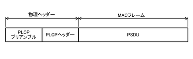
- the IEEE802.11a / b / g frames are all the PLCP (Physical Layer Convergence Protocol) preamble and PLCP header corresponding to the physical header, and the PSDU (PHY Server Service) corresponding to the MAC (Media ACces Control) frame. (Unit) field.
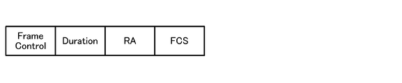
- 11A to 11C show the PSDU format of each frame of RTS, CTS / ACK, and DATA defined in IEEE 802.11.
- a frame control field and a duration field are defined in common.
- the frame control has a further subdivided format. For example, various types of information such as the type of the frame, the version of the protocol, the presence / absence of retransmission, and data path information are described.
- a counter value called NAV Network Allocation Vector
- the counter value indicates, for example, the transmission completion time of the subsequent ACK frame.
- the frame receiving station that is not the destination of the frame sets the NAV counter value based on the information described in the duration, and refrains from the transmission operation over the communication sequence unit.
- a Receiver Address (RA) indicating a destination and a Transmitter Address (TA) indicating a transmission source are described.
- the RTS and the transmission source address (TA) of the DATA frame are copied to the Receiver Address (RA) following the Duration, respectively.
- the DATA frame includes a plurality of address fields Addr1 to 4 following Duration, and is used for specifying the source and destination communication stations and the like. Also, in the Frame Body following the address field, net information provided to the upper layer is stored.
- FCS Framework Check Sequence
- CRC Cyclic Redundancy Check
- RTS / CTS communication sequence An example of an RTS / CTS communication sequence will be described with reference to FIG.
- STA2 there are four communication stations STA2, STA0, STA1, and STA3. Only adjacent communication stations are located in the radio wave reachable range, STA3 is a hidden terminal for STA0, and STA2 is for STA1. Assuming that STA0 wants to transmit information to STA1 using the RTS / CTS handshake in a communication environment that is a hidden terminal.
- STA0 monitors the media state for a predetermined frame interval DIFS (Distributed Inter Frame Space), and performs random backoff (Backoff) if there is no transmission signal during this period. Further, when there is no transmission signal during this period, an exclusive channel use transmission right (Transmission Opportunity: TXOP) is obtained, and an RTS frame addressed to STA1 is transmitted at time T1.
- TXOP Transmission Opportunity
- the Frame Control field of the RTS frame information indicating that the frame is RTS is described
- the Duration field the time until the transmission / reception transaction related to the frame ends (that is, the time until time T8).
- the RA field describes the address of the destination STA1
- the TA field describes the address of STA0 itself.
- This RTS frame is also received by STA2, which is an adjacent station of STA0.
- STA2 recognizes that the frame is an RTS frame from the Frame Control field and recognizes that the frame is not addressed to itself
- the STA2 detects the virtual carrier sense, that is, until the time T8 when the transmission / reception transaction ends. It recognizes that it is occupied and enters a transmission non-permission state without performing physical carrier sense. This operation of disabling the transmission is realized by setting a NAV counter value based on the information described in the Duration field and refraining from transmitting until the counter value disappears. Also called.
- the STA1 when the STA1 receives the RTS frame in which the address of the local station is described in the RA, the STA1 can recognize that the adjacent station STA0 in which the address is described in the TA wants to transmit information to the local station. Then, STA1 returns a CTS frame at time T3 when a predetermined frame interval SIFS (Short IFS) has elapsed from time T2 when reception of this RTS frame is completed.
- SIFS Short IFS
- the FrameControl field of the PSDU in this CTS field describes that the frame is a CTS frame
- the Duration field indicates the time until the transmission / reception transaction related to the frame ends (that is, the time until time T8). Information is described, and the address of the transmission source (STA0) described in the TA field of the RTS frame is copied in the RA field.
- This CTS frame is also received by STA3 which is an adjacent station of STA1, and when STA3 recognizes that the frame is a CTS frame from the Frame Control field and recognizes that the frame is not addressed to the own station from the RA field, virtual carrier sense That is, until the time T8 when the transmission / reception transaction ends, it is recognized that the medium is occupied, and the transmission is not permitted without performing physical carrier sense.
- STA0 can recognize that STA1 has confirmed the transmission start request from the local station when receiving the CTS frame in which the address of the local station is described in RA. Then, STA0 starts transmitting the DATA frame at time T5 when a predetermined frame interval SIFS has elapsed from time T4 when reception of the CTS frame is completed.
- each of the hidden terminals STA2 and STA3 lowers the NAV and returns to a normal transmission / reception state.
- the peripheral stations STA2 and STA3 that have received at least one of RTS and CTS shift to a transmission disabled state.
- STA0 and STA1 can transmit information from STA0 to STA1 and return an ACK from STA1 without being interrupted by a sudden transmission signal from a peripheral station. That is, by using the RTS / CTS handshake together with the CSMA / CA control procedure, the overhead of collision in an overload state may be reduced.
- the CSMA / CA control procedure is effective not only for intra-network interference but also for inter-network interference.
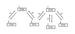
- FIG. 13 there is a network composed of STA1 and STA2 connected to STA0 as an access point, and a network composed of STA3 and STA5 connected to STA4 as an access point.
- control is performed so that unnecessary collisions with peripheral stations do not occur by the virtual carrier sense mechanism as described above. Therefore, even if STA2 and STA3 exist within the range where the signals reach each other, STA2 receives interference from the signal from STA3 while receiving the signal from STA0 by setting NAV. This situation can be avoided.
- IEEE802.11a / g standard a communication speed of 54 Mbps at the maximum (physical layer data rate) using orthogonal frequency division multiplexing (OFDM) in a 2.4 GHz band or a 5 GHz band frequency.
- OFDM orthogonal frequency division multiplexing
- IEEE 802.11n which is an extended standard, employs a MIMO (Multi-Input Multi-Output) communication method to realize a high throughput (HT) exceeding 100 Mbps.
- MIMO is a communication system that includes a plurality of antenna elements on both the transmitter side and the receiver side, and realizes a spatially multiplexed stream (well known).
- the IEEE 802.11ac Working Group aims to develop a wireless LAN standard that uses a frequency band of 6 GHz or less and a data transmission speed exceeding 1 Gbps.
- multi-user MIMO MU-MIMO
- SDMA Space
- signals transmitted from multiple antenna elements can be subjected to signal processing by multiplying the transmission / reception signals of multiple antenna elements to perform spatial separation of signals received by multiple users at the same time.
- By multiplying the values and transmitting a plurality of signals can be simultaneously distributed to a plurality of users.
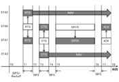
- FIG. 14 shows an example of a transmission / reception sequence using the RTS / CTS handshake in the space division multiple access system.
- STA0 there are three communication stations STA0, STA1, and STA2, and STA0 transmits data to STA1 and STA2 at the same time.
- STA0 performs physical carrier sense in advance to confirm that the medium is clear, and after backoff is performed, RTS indicating that information will be transmitted to STA1 and STA2 by space division multiple access from now on Send a frame.
- RTS the format of the RTS frame used here is not necessarily shown in FIG. 11A.
- a name different from RTS may be defined in the standard.
- STA1 and STA2 In response to receiving the RTS frame, STA1 and STA2 transmit each CTS frame (CTS-1, CTS2) at the same time to indicate that information can be received.
- CTS-1 CTS2
- the CTS frame used here is not necessarily shown in FIG. 11B, and it is assumed that STA0 has a format that can separate both signals.
- a name different from CTS may be defined in the standard.
- STA0 calculates the weight value in each antenna element necessary for spatially separating these signals based on the received CTS-1 and CTS-2 received signals (ie, learning the antenna coefficient), Both signals are received separately. Furthermore, STA0 transmits DATA frames (DATA-1, DATA-2) to STA1 and STA2 simultaneously using this weight value. DATA-1 and DATA-2 are frames transmitted with signals transmitted in consideration of the antenna weight coefficient so that interference does not occur at the destination. STA1 is DATA-1, and STA2 is DATA-2. Each can be received.
- STA1 and STA2 each return an ACK frame (ACK-1, ACK-2) when receiving the DATA frame is completed. Then, STA0 receives these ACK frames, and completes the data transmission sequence to a plurality of stations using space division multiple access.
- FIG. 14 shows a sequence example in which information transmission is performed using the RTS / CTS handshake
- a frame exchange sequence other than this can be applied to simultaneous data delivery by space division multiple access.
- which communication sequence is used is not directly related to the gist of the present invention, and will not be described further in this specification.
- inter-network interference can be avoided by the CSMA / CA control procedure.
- the time management for securing the bandwidth of the communication station is relatively lenient.
- space division multiple access it is necessary to secure bands for all the communication stations to be multiplexed, and time management is required to be more strict.
- STA0 needs to transmit data to a plurality of communication partners STA1 and STA2 at the same time. That is, STA0 needs to ensure a state in which both STA1 and STA2 that are the destinations can transmit and receive at the timing of starting transmission of a plurality of DATA frames (DATA-1 and DATA-2).
- the space division multiple access system when a communication station in which a part of the wireless network is placed in the radio wave coverage and interferes with each other in the position, the space division multiple access system is operated efficiently, for example, FIG. It is preferable that the transmission / reception sequence units for each network can be arranged so as not to overlap in time as shown in FIG.
- FIG. 17 shows another communication station arrangement example in which a plurality of networks overlap.
- STA1 is within the reach of radio waves with STA4.
- the access point STA4 is within the interference range with the terminal station STA1 connected to another network, the same problem as described above occurs, and the utilization efficiency of the wireless network is significantly deteriorated.
- Patent Documents 2 and 3 do not assume space division multiple access.
- the problem of inter-network interference appears more markedly than when the CSMA / CA system procedure is performed in a normal wireless LAN system. For this reason, the present inventors think that a methodology for finding and coordinating the problem of inter-network interference earlier is necessary.
- An object of the present invention is to provide an excellent communication system, communication apparatus, communication method, and computer capable of suitably performing communication operations by applying space division multiple access in which wireless resources on the space axis are shared by a plurality of users. ⁇ To provide a program.
- a further object of the present invention is to provide an excellent communication system, communication apparatus and communication method, and computer program capable of suitably realizing space division multiple access while avoiding interference between networks.
- the invention according to claim 1 is a communication system including a plurality of communication stations including a communication station that performs space division multiple access using an array antenna. And When a base station and one or more terminal stations perform a transmission / reception sequence unit for performing antenna transmission and information transmission by space division multiple access using the learned antenna coefficient, the base station performs its own network. Transmitting a first frame for notifying the one or more terminal stations of time information related to the transmission / reception sequence unit scheduled in step S1, and the one or more terminal stations receiving the first frame in response to the reception of the first frame. A second frame for notifying the neighboring station of time information about the It is a communication system.
- system here refers to a logical collection of a plurality of devices (or functional modules that realize specific functions), and each device or functional module is in a single housing. It does not matter whether or not (hereinafter the same).
- the terminal station receives the second frame from any of the peripheral stations, and receives the network of the peripheral station. Is configured to transmit a third frame for notifying the base station of time information related to the second transmission / reception sequence unit scheduled in (1).
- the base station uses the time information related to the second transmission / reception sequence unit obtained by decoding the received third frame.
- the second transmission / reception sequence unit is configured to adjust the start time of the transmission / reception sequence unit scheduled in the local network so as not to overlap with the second transmission / reception sequence unit.
- the first frame, the second frame, and the third frame are transmitted as a management frame.
- the first frame, the second frame, and the third frame are transmitted to the broadcast address.
- the second frame is transmitted from the terminal station as a frame addressed to the base station.
- the invention according to claim 7 of the present application is A communication unit capable of space division multiple access using an array antenna; A control unit for controlling a communication operation by the communication unit; With When the control unit operates as a base station and performs transmission / reception sequence units for performing information transmission by space division multiple access using one or more terminal stations, learning of antenna coefficients and the learned antenna coefficients To transmit a first frame for notifying the one or more terminal stations of time information related to a transmission / reception sequence unit scheduled in the local station network, and from the at least one of the one or more terminal stations to the network of the peripheral station.
- the second transmission / reception sequence unit In response to the reception of the third frame for notifying time information related to the scheduled second transmission / reception sequence unit, the second transmission / reception sequence unit does not overlap with the second transmission / reception sequence unit on the time axis. Adjust the start time of the scheduled send / receive sequence unit, It is a communication device.
- the invention according to claim 8 of the present application is a communication method for performing space division multiple access using an array antenna, and operates as a base station between one or more terminal stations, When performing transmission / reception sequence units that perform information transmission by space division multiple access using learning of antenna coefficients and learned antenna coefficients, Transmitting a first frame for notifying the one or more terminal stations of time information related to a transmission / reception sequence unit scheduled in the network of the local station; Receiving a third frame notifying time information related to a second transmission / reception sequence unit scheduled in a network of peripheral stations from at least one of the one or more terminal stations; Based on the time information about the second transmission / reception sequence unit obtained by decoding the received third frame, it is scheduled in the local station network so as not to overlap the second transmission / reception sequence unit on the time axis. Adjusting a start time of a transmission / reception sequence unit to be performed; Is a communication method.
- the invention according to claim 9 of the present application is a computer program described in a computer-readable format so that a communication device executes processing for transmitting a frame on a computer, and the computer includes: Communication unit capable of space division multiple access using an array antenna, A control unit for controlling a communication operation by the communication unit; Function as When the control unit operates as a base station and performs transmission / reception sequence units for performing information transmission by space division multiple access using one or more terminal stations, learning of antenna coefficients and the learned antenna coefficients To transmit a first frame for notifying the one or more terminal stations of time information related to a transmission / reception sequence unit scheduled in the local station network, and from the at least one of the one or more terminal stations to the network of the peripheral station.
- the second transmission / reception sequence unit In response to the reception of the third frame for notifying time information related to the scheduled second transmission / reception sequence unit, the second transmission / reception sequence unit does not overlap with the second transmission / reception sequence unit on the time axis. Adjust the start time of the scheduled send / receive sequence unit, It is a computer program.
- the computer program according to claim 9 of the present application defines a computer program described in a computer-readable format so as to realize predetermined processing on a computer.
- a cooperative action is exhibited on the computer, and the computer program operates as a base station in the network. The same effect as the communication system can be obtained.
- the invention according to claim 10 of the present application is a communication system including a plurality of communication stations including a communication station that performs space division multiple access using an array antenna, When performing transmission / reception sequence units that perform antenna transmission and information transmission by space division multiple access using the learned antenna coefficients between multiple communication stations, the information transmission source communication station is scheduled in its own network. Transmitting a first frame for notifying one or more communication stations serving as information transmission destinations of time information relating to a transmission / reception sequence unit to be transmitted, and the one or more communication stations serving as the information transmission destinations receiving the first frame In response to each of the second frames for notifying the peripheral station of time information related to the transmission / reception sequence unit, It is a communication system.
- one or more communication stations serving as information transmission destinations receive the second frame from any of the peripheral stations.
- a third frame for notifying the information transmission source communication station of time information related to the second transmission / reception sequence unit scheduled in the network of the peripheral station is configured to be transmitted.
- the invention according to claim 12 of the present application is the communication system according to claim 11, wherein the communication station as the information transmission source obtains the second transmission / reception sequence unit obtained by decoding the received third frame.
- the start time of the transmission / reception sequence unit scheduled in the network of the local station is adjusted so as not to overlap with the second transmission / reception sequence unit on the time axis.
- the first frame, the second frame, and the third frame are transmitted as a management frame.
- the invention according to claim 14 of the present application is the communication system according to claim 11, wherein the first frame, the second frame, and the third frame are transmitted as a beacon frame or a probe response frame.
- the first frame, the second frame, and the third frame are transmitted to the broadcast address.
- the second frame is transmitted from the information transmission destination communication station as a frame addressed to the information transmission source communication station.
- the invention according to claim 17 of the present application is A communication unit capable of space division multiple access using an array antenna; A control unit for controlling a communication operation by the communication unit; With The control unit is a transmission / reception sequence unit for performing information transmission by space division multiple access using learning of an antenna coefficient and the learned antenna coefficient with one or more communication stations as an information transmission destination as an information transmission source When transmitting, a first frame for notifying one or more communication stations as the information transmission destination of time information related to a transmission / reception sequence unit scheduled in the network of the local station is transmitted, and one or more of the information transmission destinations are transmitted.
- the invention according to claim 18 of the present application is a communication method for performing space division multiple access using an array antenna, and as an information transmission source, with one or more communication stations serving as information transmission destinations
- Transmitting a first frame for notifying one or more communication stations as the information transmission destination of time information related to a transmission / reception sequence unit scheduled in the network of the local station Receiving a third frame for notifying time information related to a second transmission / reception sequence unit scheduled in a network of peripheral stations from at least one of the one or more communication stations serving as the information transmission destination; Based on the time information about the second transmission / reception sequence unit obtained by decoding the received third frame, it is scheduled in the local station network so as not to overlap the second transmission / reception sequence unit on the time axis. Adjusting a start time of a transmission / reception sequence unit to be performed; Is a communication method.
- the invention according to claim 19 of the present application is a computer program described in a computer-readable format so that a communication device executes processing for transmitting a frame on a computer, the computer comprising: Communication unit capable of space division multiple access using an array antenna, A control unit for controlling a communication operation by the communication unit; Function as The control unit is a transmission / reception sequence unit for performing information transmission by space division multiple access using learning of an antenna coefficient and the learned antenna coefficient with one or more communication stations as an information transmission destination as an information transmission source When transmitting, a first frame for notifying one or more communication stations as the information transmission destination of time information related to a transmission / reception sequence unit scheduled in the network of the local station is transmitted, and one or more of the information transmission destinations are transmitted.
- the computer program according to claim 19 of the present application defines a computer program written in a computer-readable format so as to realize predetermined processing on a computer.
- a cooperative action is exhibited on the computer, and the network operates as an information transmission source communication station within the network. The same effect as that of the communication system according to item 10 can be obtained.
- an excellent communication system, communication apparatus, communication method, and computer that can suitably perform communication operations by applying space division multiple access in which wireless resources on the space axis are shared by a plurality of users. ⁇ Provide programs.
- the base station starts the transmission / reception sequence unit by itself based on the time information of the transmission / reception sequence unit in the peripheral network. Place the time in a time zone that is not used by the adjacent network or device. As a result, even when exclusive arrangement of frequency channels is difficult, channels can be used by multiple wireless networks or wireless communication devices in time division, and efficient space division multiple access can be realized.
- FIG. 1 is a diagram illustrating a configuration example of a communication device that realizes space division multiple access.
- FIG. 2 is a diagram showing an example of a communication sequence for preventing a transmission / reception sequence unit of each network from colliding in the network configuration shown in FIG.
- FIG. 3 shows an example of a communication sequence when an access point transmits information related to a transmission / reception sequence unit such as “time information” using a beacon frame and a terminal station transmits information using an action frame.
- FIG. FIG. 4 is a diagram showing an example of a communication sequence when information related to a transmission / reception sequence unit such as “time information” is included in a general frame and transmitted.
- FIG. 5 is a diagram showing a configuration example of a time information element TIME IE that publishes “time information” related to a transmission / reception sequence unit.
- FIG. 6A is a diagram showing a PSDU format of an RTS frame in which a time information element is posted.
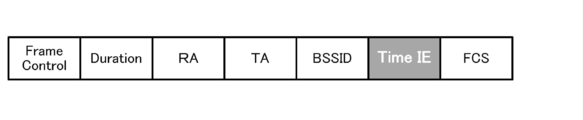
- FIG. 6B is a diagram showing a PSDU format of a CTS / ACK frame in which a time information element is posted.
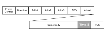
- FIG. 6C is a diagram showing a PSDU format of a DATA frame in which a time information element is posted.
- FIG. 6D is a diagram showing the PSDU format of the action frame in which the time information element is posted.
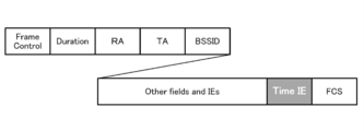
- FIG. 6E is a diagram showing the PSDU format of each frame of a beacon or probe response in which a time information element is posted.
- FIG. 7 is a diagram showing a configuration example in which a time information element is posted in a part of an Aggregated frame in which a plurality of MPDUs are stored in one PSDU.
- FIG. 8 is a diagram illustrating an example of a communication sequence in which each communication station is controlled so as not to collide with each other in an ad hoc communication environment.
- FIG. 9 shows in FIG. 9 that time information in transmission / reception sequence units is notified through beacon frames transmitted at predetermined beacon transmission timings, and each communication station schedules the time in the transmission / reception sequence units of its own station sequentially. It is the figure which showed a mode.
- FIG. 10 is a diagram illustrating a format of main frames used in the RTS / CTS handshake in the IEEE 802.11 system.
- FIG. 10 is a diagram illustrating a format of main frames used in the RTS / CTS handshake in the IEEE 802.11 system.
- FIG. 11A is a diagram showing a PSDU format of an RTS frame defined in IEEE 802.11.
- FIG. 11B is a diagram showing the PSDU format of each frame of CTS / ACK defined by IEEE 802.11.
- FIG. 11C is a diagram showing a PSDU format of a DATA frame defined in IEEE 802.11.
- FIG. 12 is a diagram for explaining an example of a communication sequence of RTS / CTS.
- FIG. 13 shows a state in which a network composed of STA1 and STA2 connecting with STA0 as an access point and a network composed of STA3 and STA5 connecting with STA4 as an access point are adjacent to each other.
- FIG. 14 is a diagram showing an example of a transmission / reception sequence using the RTS / CTS handshake in the space division multiple access system.
- FIG. 15 is a diagram illustrating a situation in which the transmission sequence of STA0 and the transmission sequence of STA4 overlap in time and interference occurs between STA1 and STA3.
- FIG. 16 is a diagram showing a state in which transmission / reception sequence units for each network are arranged so as not to overlap in time.
- FIG. 17 is a diagram illustrating another communication station arrangement example in which a plurality of networks overlap.
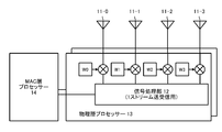
- FIG. 1 shows a configuration example of a communication apparatus that realizes space division multiple access.
- the illustrated communication apparatus is equipped with a plurality of transmission / reception antennas 11-0, 11-1,.
- the signal processing unit 12 handles one single stream by multiplying input / output signals to the antennas 11-0, 11-1,... By weight values W0 to W3, respectively. be able to.
- a transmission / reception system including such a physical layer processor 13 in parallel, space division multiplexing is possible, and the communication apparatus can handle a plurality of streams.
- These physical layer processors 13 installed in parallel are connected to the MAC layer processor 14 to perform signal processing necessary for the wireless LAN system.
- a plurality of MAC instances may operate in parallel.
- the communication apparatus shown in FIG. 1 can operate as either an access point or a terminal station in the infrastructure mode, or can perform a communication operation autonomously in the ad hoc mode. .
- each of the communication stations STA0 to STA5 can be configured by the communication apparatus shown in FIG.
- a network composed of STA1 and STA2 connected to STA0 as an access point and a network composed of STA3 and STA5 connected to STA4 as an access point are adjacent to each other.
- STA2 and STA3 are in a range where the radio waves of each other reach, but STA0 and STA4 are disposed where they cannot receive the radio waves of each other.
- FIG. 2 shows an example of a communication sequence for preventing transmission / reception sequence units of each network from colliding with each other in the network configuration shown in FIG.
- the time utilization information of the transmission sequence is exchanged between different networks or between devices that are not adjacent to each other. Based on this information, the communication station that starts the transmission sequence determines the transmission sequence time of its own station. It is arranged in a time zone that is not used by the adjacent network or adjacent device.
- STA0 transmits a message (MSG-) containing “time information” including information such as the start time of the transmission sequence scheduled by the station in the future, the length of the transmission sequence to be continued, and the transmission sequence occurrence interval.
- MSG-00 describes that the illustrated transmission / reception sequence unit-0 is scheduled from time t0.
- each transmission / reception sequence unit although not shown in FIG. 2, information transmission from an access point to a plurality of terminal stations is performed using, for example, an RTS / CTS handshake as shown in FIG. It is.
- a series of sequences for performing antenna transmission between an information transmission source and an information transmission destination and performing information transmission by space division multiple access using the learned antenna coefficient is referred to as a “transmission / reception sequence unit”. Define.
- the STA1 and the STA2 When the STA1 and the STA2 receive the message MSG-00, they can obtain information on the timing at which the STA0, which is the transmission source of the message, plans the transmission / reception sequence unit-0 in the future.
- STA1 and STA2 can perform the power saving operation until time t0 when it is determined that frame transmission / reception is not necessary until the next transmission sequence unit-0 start time t0.
- the message MSG-00 including “time information of transmission sequence scheduled by the local station” transmitted from the STA0 may be transmitted only to a communication station in communication with the local station. Since the information is desired to be received by the communication station of the other network to be wrapped, it is desirable that the information is transmitted to the broadcast address and transmitted to the communication station belonging to another logical network.
- STA1 and STA2 transmit time information including the same contents as the time information notified by STA-00 to MSG-00 in order to further transmit the time information of transmission / reception sequence unit-0 scheduled by STA0 to peripheral stations.
- the message MSG-02 transmitted by the STA2 corresponds to this.
- STA1 since STA1 cannot confirm the presence of other peripheral stations, STA1 determines that transfer to the periphery of MSG-00 is unnecessary, and does not transmit a message equivalent to MSG-02 in the illustrated example. . However, STA1 may transmit a message equivalent to MSG-02 regardless of the situation of the peripheral station.
- the message MSG-02 including the “time information of the transmission / reception sequence scheduled by the communication partner” transmitted from the STA 2 may be transmitted only to the communication station in communication with the own station. Since the information is also desired to be received by communication stations in other overlapping networks, it is desirable that the information be transmitted to the broadcast address and transmitted to communication stations belonging to other logical networks. .
- the STA3 When the STA3 receives the message MSG-02 transmitted by the STA2 as a peripheral station, the STA3 can recognize at which timing STA2 will perform the transmission / reception sequence unit-0 in the future.
- the STA3 may determine whether or not the timing of the transmission / reception sequence unit-0 used by the STA2 overlaps with the timing of the transmission / reception sequence unit used by the local station.
- the message MSG in FIG. 2 is used to notify the STA-02, which is the access point of the communication partner, of the time information of the MSG-02 broadcast from the STA 1.
- the STA3 may transmit the message MSG-03 to the STA4 without determining whether or not the timings of the transmission / reception sequence units overlap as described above.
- the STA4 can grasp at what time the STA3 may receive interference from the peripheral station by decoding the content of the message MSG-03 received from the STA3. Based on this information, the STA 4 schedules the scheduled time of its own transmission / reception sequence unit-4 so as not to overlap the transmission / reception sequence unit-0. In the example shown in FIG. 2, the STA 4 arranges the transmission / reception sequence unit-4 including the address for the STA 3 from the time t4.
- the gist of the present invention is not limited to a specific method for determining whether or not the transmission / reception sequence units of each logical network overlap.
- a methodology as disclosed in Patent Document 3 can be used to determine the overlap of transmission / reception sequence units.
- the STA 4 transmits a message MSG-44 including the schedule information of the transmission / reception sequence unit-4 as “time information” similar to the above.
- the message MSG-44 describes that the transmission / reception sequence unit-4 is scheduled from time t4.
- the STA3 and the STA5 receive the message MSG-44 and decode the contents, the STA3 and the STA5 obtain information on the timing at which the STA4 plans the transmission / reception sequence unit -4 in the future.
- the message MSG-44 including “the time information of the transmission sequence scheduled by the local station” transmitted from the STA 4 may be transmitted only to the communication stations that are in communication with the local station. . However, since this information is also desired to be received by other communication stations in the overlapping network, the message MSG-44 is transmitted to the broadcast address and received by communication stations belonging to other logical networks. It is desirable to be transmitted.
- the communication sequence example for avoiding a network collision shown in FIG. 2 assumes a case where terminal stations (STA2, STA3) that are not access points interfere with each other as shown in FIG.
- terminal stations STA2, STA3
- FIG. 17 there may be a situation in which the terminal station STA1 directly interferes with an access point STA4 other than the access point STA0 to which the own station is connected (or accommodates the own station).
- the transmission message MSG-01 of the terminal station STA1 is directly transmitted to the other access point STA4.
- the STA4 can recognize the time zone used by the overlapping wireless networks by decoding the content of the message MSG-01, so as described above, the schedule of the transmission / reception sequence unit-4 of its own station The time is scheduled so as not to overlap with the transmission / reception sequence unit-0.
- a message (such as MSG-00) used in the communication sequence shown in FIG. 2 can be transmitted as an action frame for independently posting “time information”.
- An action frame is a type of management frame that requires action between communication stations, and is also defined in IEEE 802.11.
- information related to a transmission / reception sequence unit such as “time information” may be included in a frame such as a beacon frame or a probe response frame and transmitted.
- a beacon frame is a frame for broadcasting information necessary for network operation
- a probe response frame is a response frame from an access point to a probe request frame transmitted for network detection from a terminal station. It is. Both beacons and probe responses are also defined in IEEE 802.11 as frames for posting general control information. It can also be included in a part of other general frames.
- STA0 schedules transmission / reception sequence unit-0, it transmits a beacon frame (corresponding to MSG-00) in which information such as “time information” is posted at a predetermined beacon transmission timing.
- the STA1 and the STA2 When the STA1 and the STA2 receive the beacon frame from the STA0, they can obtain information on the timing at which the STA0 is scheduled to transmit / receive sequence unit-0 in the future.
- STA2 transmits an action frame (corresponding to MSG-02) including “time information” in order to further transmit the time information of transmission / reception sequence unit-0 scheduled by STA0 to peripheral stations.
- STA1 cannot confirm the presence of other peripheral stations, it determines that transfer to the periphery is unnecessary and does not transmit an action frame in the illustrated example.
- STA3 When STA3 receives action frame MSG-02 from STA2, which is a peripheral station, STA3 can recognize at which timing STA2 will perform transmission / reception sequence unit-0 in the future. Here, the STA3 determines whether the timing of the transmission / reception sequence unit-0 used by the STA2 and the timing of the transmission / reception sequence unit used by the STA2 are overlapped. An action frame (corresponding to MSG-03) is transmitted in order to notify “time information” and the like to the STA 4 which is the other access point. Alternatively, the STA 3 may transmit the action frame to the STA 4 without determining whether or not the timings of the transmission / reception sequence units overlap as described above.
- the STA4 can grasp at what time the STA3 may receive interference from the peripheral station by decoding the content of the action frame received from the STA3. Based on this information, the STA 4 schedules the scheduled time of its own transmission / reception sequence unit-4 so as not to overlap the transmission / reception sequence unit-0. Thereafter, the STA 4 transmits a beacon frame (corresponding to MSG-44) in which information such as “time information” is posted at a predetermined beacon transmission timing.
- the STA3 When the STA3 receives the beacon frame MSG-44 from the STA4, the STA3 can obtain information on the timing at which the STA3 plans the transmission / reception sequence unit-4 in the future. Then, the STA 3 transmits an action frame (MSG-43) including “time information” in order to further transmit the time information of the transmission / reception sequence unit-4 to the peripheral stations.
- an action frame MSG-43 including “time information” in order to further transmit the time information of the transmission / reception sequence unit-4 to the peripheral stations.
- STA0 and STA4 which are access points repeatedly transmit beacon frames including information corresponding to MSG-00 or MSG-44 each time the beacon transmission timing arrives.
- FIG. 4 shows an example of a communication sequence in the case where information related to a transmission / reception sequence unit such as “time information” is transmitted in a general frame in the network configuration shown in FIG.
- the method of including information in a frame includes multiplexing.
- “time information” and the like are transmitted through an RTS / CTS handshake, and control frames such as RTS, CTS, and ACK are used as general frames.
- RTS Radio Transport / CTS handshake
- control frames such as RTS, CTS, and ACK are used as general frames.
- RTS frame and a CTS frame are called by different names.
- STA0 performs physical carrier sense in advance to confirm that the medium is clear, and after backoff is performed, RTS indicating that information will be transmitted to STA1 and STA2 by space division multiple access from now on Send a frame.
- STA0 includes information such as “time information” of the scheduled transmission / reception sequence unit-0 in the RTS frame by multiplexing or the like.
- STA1 and STA2 transmit each CTS frame (CTS-1, CTS2) at the same time to indicate that information can be received.
- CTS-1, CTS2 CTS-2, CTS2
- the STA1 and the STA2 transmit “time information” and the like to each CTS frame in order to further transmit the time information of the transmission / reception sequence unit-0 scheduled by the STA0 to the peripheral station (hidden terminal of the STA0).
- the STA1 and the STA2 also include “time information” in the transmission / reception sequence unit in the adjacent network acquired from the peripheral station in the CTS frame.
- STA0 calculates the weight value in each antenna element necessary for spatially separating these signals based on the received CTS-1 and CTS-2 received signals, and separates and receives both signals. Furthermore, STA0 transmits DATA frames (DATA-1, DATA-2) to STA1 and STA2 simultaneously using this weight value. At this time, the STA0 includes information such as “time information” of the scheduled transmission / reception sequence unit-0 in each DATA frame (DATA-1, DATA-2).
- DATA-1 and DATA-2 are frames transmitted with signals transmitted in consideration of the antenna weight coefficient so that interference does not occur at the destination.
- STA1 is DATA-1
- STA2 is DATA-2. Each can be received.
- STA1 and STA2 each return an ACK frame (ACK-1, ACK-2) when receiving the DATA frame is completed.
- the STA1 and the STA2 transmit “time information” or the like to each ACK frame in order to further transmit the time information of the transmission / reception sequence unit-0 scheduled by the STA0 to the peripheral station (hidden terminal of the STA0).
- STA1 and STA2 also include “time information” in the transmission / reception sequence unit in the adjacent network acquired from the peripheral station in the ACK frame.
- STA0 receives these ACK frames, and completes the data transmission sequence to a plurality of stations using space division multiple access.
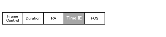
- FIG. 5 shows a configuration example of the information element TIME IE that publishes “time information” related to transmission / reception sequence units.
- the information element is composed of the following fields.
- Element ID An identifier indicating that the element publishes time information.
- Length Indicates the length of the element (the time information element may be variable length).
- Time A value indicating the transmission time of the frame.
- TXID an identifier for identifying a transmission / reception sequence unit (the identifier is composed of a numerical value assigned by a communication station that determines a transmission / reception sequence unit and a flag for identifying transmission / reception. Reference is made by referring to this flag. Thus, it is possible to determine whether the time information is information related to transmission or information related to reception).
- SEQ Time Scheduled start time of the transmission / reception sequence unit (represented based on the time indicated in the Time field).
- SEQ Duration Scheduled duration of the transmission / reception sequence unit.
- SEQ Interval Interval (cycle) in the transmission / reception sequence unit.
- the fields (4) to (7) above are a set of “time information” for one transmission / reception sequence unit, and a plurality of (4) to (7) are included in the information element TIME IE. By displaying the set, “time information” of a plurality of transmission / reception sequence units can be expressed simultaneously. Time information is transmitted and received in the above manner.
- FIGS. 6A to 6E show RTS, CTS / ACK, DATA, action, beacon / probe response including time information elements used in the communication sequence examples shown in FIGS.
- the PSDU format of each frame is shown.
- the configuration example of the TIME IE field included in each frame is as shown in FIG. 5, and the other fields are as already described.
- a time information element is added to a general frame such as RTS, CTS / ACK, and DATA in addition to a normal frame field. To be sent. As shown in FIG.
- a time information element is stored in the payload portion and transmitted. Further, as shown in FIG. 6E, in addition to other fields and information elements posted in normal beacons and probe responses, time information elements are added and transmitted.
- FIG. 7 shows a configuration example in which a time information element is posted in a part of an Aggregated frame in which a plurality of MPDUs are stored in one PSDU.
- MPDU MAC Protocol Data Unit
- MMPDU MAC Management Protocol Data Unit
- FIG. 7 shows a configuration example in which a time information element is posted in a part of an Aggregated frame in which a plurality of MPDUs are stored in one PSDU.
- five MPDUs are aggregated. Among them, the content corresponding to the action frame in which the first MPDU (MPDU-1) stores the time information element is stored.
- Subsequent MPDUs (MPDU-2, MPDU-3,...) Store contents corresponding to the data frame shown in FIG. 11A.
- an infrastructure network composed of access points and client devices connected to the access points has been taken as an example.
- wireless networks such as ad hoc networks or mesh networks where each communication station autonomously controls the behavior and establishes a link on an equal basis between each communication station.
- a method of operating the space division multiple system according to the present invention will be described by taking an ad hoc mesh network configured without the presence of a specific control station as an example.
- each communication station determines the timing of the transmission sequence at its own station with respect to its own transmission frame. For example, when there are three communication stations STA0, STA1, and STA2 that operate autonomously and communicate with each other, STA0 determines the transmission timing from STA0 to STA1 and STA2. Similarly, STA1 determines the transmission timing addressed from STA1 to STA0 and STA2, and STA2 determines the transmission timing addressed from STA2 to STA0 and STA1.
- each communication station STA0 to STA2 periodically transmits a beacon signal to each communication station for the purpose of reporting autonomous control information to each peripheral station.
- Each communication station STA0 to STA2 is also provided with a capability of transmitting a probe response frame as necessary when receiving a probe request frame.
- the communication stations STA0 to STA5 are arranged as shown in FIG. 13 to form a mesh network, or a plurality of wireless networks are overlapped.
- each communication station is a communication station that performs an autonomous operation. However, each communication station is within the reach of radio waves only with adjacent communication stations.
- Each communication station simultaneously delivers data to a plurality of communication stations using space division multiple access.
- STA0 communicates with STA1 and STA2 using a communication sequence of space division multiple access as shown in FIG.
- the STA 4 also communicates with the STA 3 and the STA 5 by using a space division multiple access communication sequence as shown in FIG.
- STA1 wants to transmit data at the same time as STA0 and STA3, similarly, it transmits by space division multiple access.
- FIG. 8 shows an example of a communication sequence in which each communication station is controlled so as not to collide with each other in such an ad hoc communication environment.
- STA0 transmits a beacon frame (corresponding to MSG-0) in which information such as “time information” in a scheduled transmission / reception sequence unit is posted at a predetermined beacon transmission timing.
- the STA1 and the STA2 When the STA1 and the STA2 receive the beacon frame from the STA0, they can obtain information on the timing at which the STA0 is scheduled for a transmission / reception sequence unit in the future. Based on this information, the STA1 array and the STA2 may schedule the scheduled time in the transmission / reception sequence unit of the local station so as not to overlap with the transmission / reception sequence unit of the STA0.
- the message MSG-0 including time information may be sent only to communication stations that are in the process of communicating with the local station, but it should be received by communication stations in other overlapping networks.
- To the broadcast address and is preferably transmitted so as to be received by communication stations belonging to other logical networks.
- the STA1 and the STA2 add new time information by adding the time information in the transmission / reception sequence unit received from the MSG-0 from the STA0 to the time information in the transmission / reception sequence unit of the local station. Generate and transmit frames for transmitting this time information to the peripheral stations.
- the message transmitted by STA1 as MSG-1 and the message transmitted by STA2 as MSG-2 correspond to this.
- MSG-1 and MSG-2 are information that is also desired to be received by the communication stations of other overlapping networks, so they are sent to the broadcast address and belong to other logical networks. It is desirable to be transmitted so as to be received also by the communication station.
- STA1 posts and transmits message MSG-1 in the action frame
- STA2 transmits message MSG-2 in the beacon frame and action frame.
- the STA 4 transmits a beacon frame (corresponding to MSG-4) in which information such as “time information” in a scheduled transmission / reception sequence unit is posted at a predetermined beacon transmission timing.
- STA2 also transmits message MSG-2 including time information to the peripheral station even in the action frame.
- STA0 and STA3 Upon receiving the action frame from STA2, STA0 and STA3 obtain information on the timing at which STA2 will schedule transmission / reception sequence units in the future. , Schedule not to overlap the transmission / reception sequence unit of STA0.
- each communication station summarizes the time information in the transmission / reception sequence unit of its own station and the time information in the transmission / reception sequence unit received from the peripheral station.
- "time information" is generated and transmitted to the peripheral stations.
- Each communication station compares the time information of its own transmission / reception sequence unit with the time information of the transmission / reception sequence unit received from the peripheral station, and schedules the time of its own transmission / reception sequence unit so that they do not overlap each other. As a result, the entire system is scheduled so that, for example, transmission / reception sequence units of two hops ahead do not overlap.
- FIG. 9 shows a state in which time information in transmission / reception sequence units is notified through beacon frames transmitted at predetermined beacon transmission timings, and each communication station sequentially schedules the time in the transmission / reception sequence unit of its own station. Yes.
- the gist of the present invention is not described in detail in the present invention regarding the method for determining whether or not the transmission / reception sequences overlap, but for example, a methodology as shown in Patent Document 3 can be used.
- each communication station transmits a “time information” in a transmission / reception sequence unit as an action frame that publishes alone, and a general case such as a beacon frame or a probe response frame.
- “time information” is included in a frame in which various control information is posted.
- “time information” can be included in other general frames such as RTS, CTS, DATA, ACK, and the like in a multiplex and transmitted.
- each communication station since each communication station transmits a beacon frame together, it is efficient to transmit “time information” through a beacon frame or an action frame, as shown in FIG. You might also say that.
- the frame formats shown in FIGS. 5 to 7 can be used in the same manner as frame formats for posting “time information”.
- the embodiment applied to a new wireless LAN standard such as IEEE802.11ac aiming at realizing ultra-high throughput of 1 Gbps has been mainly described, but the gist of the present invention is not limited to this. Absent.
- the present invention can be similarly applied to other wireless LAN systems in which wireless resources on the space axis are shared by a plurality of users and various wireless systems other than the LAN.
- a transmission / reception sequence unit a series of sequences for performing antenna transmission between an information transmission source and an information transmission destination and performing information transmission by space division multiple access using the learned antenna coefficient.
- a typical transmission / reception sequence is one RTS / CTS handshake as shown in FIG. 14, but the gist of the present invention is not necessarily limited to this.
- RDG Reverse Direction Grant
- IEEE 802.11n defines the RD protocol in order to further improve the efficiency of data transmission in TXOP.
Landscapes
- Engineering & Computer Science (AREA)
- Computer Networks & Wireless Communication (AREA)
- Signal Processing (AREA)
- Mobile Radio Communication Systems (AREA)
Abstract
ネットワーク間干渉を回避しながら空間分割多元接続を好適に実現する。 異なるネットワーク間や自分自身が隣接しない機器間での送受信シーケンス単位の時間利用情報を交換し、この情報に基づいて、送受信シーケンス単位を開始する通信局は自局の送受信シーケンス単位の開始時刻を隣接ネットワークや隣接機器で利用していない時間帯に配置する。結果として、周波数チャネルの排他的な配置が困難な場合であっても時分割にて複数無線ネットワーク又は無線通信機器がチャネルを利用でき、効率的な空間分割多元接続を実現することができる。
Description
本発明は、空間軸上の無線リソースを複数のユーザーで共有する空間分割多元接続(Space Division Multuple Access:SDMA)を適用する通信システム、通信装置及び通信方法、並びにコンピューター・プログラムに係り、特に、ネットワーク間干渉を回避しながら空間分割多元接続を実現する通信システム、通信装置及び通信方法、並びにコンピューター・プログラムに関する。
無線通信は、旧来の有線通信における配線作業の負担を解消し、さらには移動体通信を実現する技術として利用に供されている。例えば、無線LAN(Local Area Network)に関する標準的な規格として、IEEE(The Institute of Electrical and Electronics Engineers)802.11を挙げることができる。IEEE802.11a/gは既に広く普及している。
IEEE802.11を始めして多くの無線LANシステムでは、CSMA/CA(Carrier Sense MultipleAccess with Collision Avoidance:搬送波感知多重アクセス)などのキャリアセンスに基づくアクセス制御手順を採り入れて、各通信局はランダム・チャネル・アクセス時におけるキャリアの衝突を回避するようにしている。また、無線通信における隠れ端末問題を解決する方法論として、「仮想キャリアセンス」を挙げることができる。仮想キャリアセンスを利用した信号送受信シーケンスの代表例は、RTS/CTSハンドシェイクである。
図10には、IEEE802.11システムにおいてRTS/CTSハンドシェイクで利用される主要なフレームのフォーマットを示している。図示のようにIEEE802.11a/b/gのフレームはいずれも、物理ヘッダーに相当するPLCP(Physical Layer Convergence Protocol)プリアンブル及びPLCPヘッダーと、MAC(Media ACces Control)フレームに相当するPSDU(PHY Service Data Unit)フィールドで構成される。また、図11A~図11Cには、IEEE802.11で定義されている、RTS、CTS/ACK、DATAの各フレームのPSDUのフォーマットを示している。
PSDUの先頭には、フレーム・コントロール(Frame Control)フィールドとデュレーション(Duration)フィールドが共通に定義されている。フレーム・コントロールは、さらに細分化されたフォーマットを有するものであり、例えば、当該フレームの種別やプロトコルのバージョン、再送の有無、データの経路情報といった各種情報が記述される。デュレーションには、NAV(Network Allocation Vector)と称されるカウンター値が設定される。カウンター値は、例えば後続のACKフレームの送信完了時刻を指すものとする。当該フレームの宛て先でないフレーム受信局は、デュレーションに記述された情報に基づいてNAVのカウンター値を設定して、通信シーケンス単位にわたり送信動作を控えるようになる。
図11Aに示すように、RTSフレームには、Durationに続いて、宛て先を示すReceiver Address(RA)と、送信元を示すTransmitter Address(TA)が記載される。また、図11Bに示すように、CTSフレーム並びにACKフレームでは、Durationの後に続くReceiver Address(RA)に、それぞれRTS、DATAフレームの送信元のアドレス(TA)がコピーされる。また、図11Cに示すように、DATAフレームには、Durationに続いて、複数のアドレス・フィールドAddr1~4が含まれ、送信元や宛先通信局他の特定を行なうために用いられる。また、アドレス・フィールドに続くFrame Bodyには、上位レイヤに提供する正味の情報が格納される。いずれのフレームも、最後尾に、32ビットのCRC(Cyclic Redundancy Check)からなるFCS(Frame Check Sequence)が付加される。例えばフレームを受信した宛て先局では、FCSを再計算して、送られてきたFCS一致するか否かをチェックする。一致しなかった場合には、そのフレームは破壊されたものとして廃棄することにより、正しいMACフレームのみを認識し、処理を行なうことになる。
RTS/CTSの通信シーケンス例を、図12を参照しながら説明する。同図では、4台の通信局STA2、STA0、STA1、STA3が存在しており、隣り合う通信局同士のみが電波の到達範囲に位置し、STA3がSTA0にとっての隠れ端末となり、STA2がSTA1にとっての隠れ端末となる通信環境下で、STA0がRTS/CTSハンドシェイクを用いてSTA1宛てに情報を送信したい状況を想定している。
STA0は、時刻T0において送信要求が発生すると、所定のフレーム間隔DIFS(Distributed Inter Frame Space)だけメディア状態を監視し、この間に送信信号が存在しなければ、ランダム・バックオフ(Backoff)を行ない、さらにこの間にも送信信号が存在しない場合に、排他的なチャネルの利用送信権(Transmission Opportunity:TXOP)を得て、時刻T1にSTA1宛てのRTSフレームを送信する。ここで、RTSフレームのFrame Controlフィールドには当該フレームがRTSであることを示す情報が記載され、Durationフィールドには当該フレームに関連する送受信トランザクションが終了するまでの時間(すなわち時刻T8までの時間)を示す情報が記載され、RAフィールドには宛先であるSTA1のアドレスが記載され、TAフィールドにはSTA0自身のアドレスが記載されている。
このRTSフレームはSTA0の隣接局であるSTA2でも受信される。STA2は、Frame Controlフィールドから当該フレームがRTSフレームであることを認識するとともに、RAフィールドから自局宛てでないことを認識すると、仮想キャリアセンス、すなわち、当該送受信トランザクションが終了する時刻T8まではメディアが占有されていることを認識し、物理キャリアセンスを行なうことなく送信不許可状態となる。この送信不許可状態となる作業は、Durationフィールドに記載された情報に基づいてNAVのカウンター値を設定し、当該カウンター値が消滅するまでは送信動作を控えることによって実現され、「NAVを立てる」とも呼ぶ。
一方、STA1は、RAに自局のアドレスが記載されたRTSフレームを受信すると、TAにアドレスが記載された隣接局STA0が自局宛てに情報を送信したい旨を認識することができる。そして、STA1は、このRTSフレームを受信終了した時刻T2から所定のフレーム間隔SIFS(Short IFS)が経過した時刻T3で、CTSフレームを返送する。このCTSフィールド内のPSDUのFrameControlフィールドには当該フレームがCTSフレームである旨が記載され、Durationフィールドには当該フレームに関連する送受信トランザクションが終了するまでの時間(すなわち時刻T8までの時間)を示す情報が記載され、RAフィールドにはRTSフレームのTAフィールドに記載された送信元(STA0)のアドレスがコピーされている。
このCTSフレームはSTA1の隣接局であるSTA3でも受信され、STA3は、Frame Controlフィールドから当該フレームがCTSフレームであることを認識するとともに、RAフィールドから自局宛てでないことを認識すると、仮想キャリアセンス、すなわち、当該送受信トランザクションが終了する時刻T8まではメディアが占有されていることを認識し、物理キャリアセンスを行なうことなく送信不許可状態となる。
一方、STA0は、RAに自局のアドレスが記載されたCTSフレームを受信すると、STA1が自局からの送信開始要求を確認したことを認識することができる。そして、STA0は、このCTSフレームを受信終了した時刻T4から所定のフレーム間隔SIFSが経過した時刻T5で、DATAフレームを送信開始する。
DATAフレーム送信が時刻T6で終了し、STA1が当該フレームを誤りなく復号することができた場合には、所定のフレーム間隔SIFSをおいて時刻T7でACKフレームを返送する。そして、STA0がこのACKフレームを受信終了する時刻T8で、1パケットの送受信トランザクションが終了する。
時刻T8になると、各隠れ端末STA2並びにSTA3は、NAVを下ろして、通常の送受信状態へと復帰する。
RTS/CTSハンドシェイクによれば、RTS又はCTSの少なくとも一方を受信できた周辺局STA2、STA3は送信不可能状態に移行する。この結果、STA0及びSTA1は、周辺局からの突然の送信信号により妨害されることなく、STA0からSTA1への情報送信、並びにSTA1からのACKの返送を行なうことができる。すなわち、CSMA/CA制御手順にRTS/CTSハンドシェイクを併用することにより、過負荷状態における衝突のオーバーヘッドの削減が図られることがある。
従来の無線LANシステムでは、CSMA/CA制御手順は、ネットワーク内干渉だけでなく、ネットワーク間干渉に関しても有効である。例えば図13に示すように、STA0をアクセスポイントとしてこれと接続するSTA1とSTA2から構成されるネットワークと、STA4をアクセスポイントとしてこれと接続するSTA3とSTA5から構成されるネットワークが隣接して存在する場合を想定する。IEEE802.11では、上述したような仮想キャリアセンスのメカニズムにより、周辺局との間で不必要な衝突が発生しないよう制御が行なわれている。したがって、STA2とSTA3が互いに信号が到達する範囲内に存在していたとしても、NAVが設定されることにより、STA2はSTA0からの信号を受信している間にSTA3からの信号により干渉を受けるといった状況を避けることができる。
ところで、IEEE802.11a/gの規格では、2.4GHz帯あるいは5GHz帯周波数において、直交周波数分割多重(Orthogonal Frequency Division Multiplexing:OFDM)を利用して、最大(物理層データレート)で54Mbpsの通信速度を達成する変調方式をサポートしている。また、その拡張規格であるIEEE802.11nでは、MIMO(Multi-Input Multi-Output)通信方式を採用して、100Mbps超の高スループット(High Throughput:HT)を実現している。ここで、MIMOとは、送信機側と受信機側の双方において複数のアンテナ素子を備え、空間多重したストリームを実現する通信方式である(周知)。
例えば、MIMO通信機のアンテナ本数を増やして空間多重するストリーム数が増加することによって、下位互換性を保ちながら、1対1の通信におけるスループットを向上させることができる。将来は、通信におけるユーザー当たりのスループットに加え、複数ユーザー全体でのスループットを向上させることが要求されている。
IEEE802.11ac作業部会では、6GHz以下の周波数帯を使い、データ伝送速度が1Gbpsを超える無線LAN規格の策定を目指しているが、その実現には、マルチユーザーMIMO(MU-MIMO)若しくはSDMA(Space Division Multuple Access)のように、空間軸上の無線リソースを複数のユーザーで共有する空間分割多元接続方式が有力である。
空間分割多元接続システムでは、複数のアンテナ素子の送信/受信信号にウエイト値を乗算して信号処理を行なうことにより、同時に受信した複数ユーザーの信号を空間分離することが可能であり、同様のウエイト値を乗算して送信することにより、複数ユーザーに向けて複数の信号を同時に配布することが可能となる。
新規の無線LAN規格で空間分割多元接続の運用を開始する際には、当該新規規格の通信機が従来規格の通信機と混在する通信環境下で動作する必要があることから、従来規格との下位互換性を十分に考慮する必要がある。従来からのIEEE802.11規格では、CSMA/CA、RTS/CTSといったキャリアセンスのメカニズムが導入されている。したがって、IEEE802.11acなどの新規規格においては、キャリアセンスと空間分割多元接続を好適に組み合わせる必要がある。
例えば、従来からのIEEE802.11規格とは下位互換性を保つフレーム・フォーマットからなるRTS、CTS、ACKフレームを用いて、従来からのIEEE802.11規格におけるキャリアセンスとアダプティブ・アレイ・アンテナによる空間分割多元接続という2つの技術を組み合わせた通信システムについて提案がなされている(例えば、特許文献1を参照のこと)。
図14には、空間分割多元接続システムにおいて、RTS/CTSハンドシェイクを利用した送受信シーケンス例を示している。図示の例では、3台の通信局STA0、STA1、STA2が存在し、STA0がSTA1及びSTA2に対して同時にデータを送信することを想定している。
STA0は、事前に物理キャリアセンスを行なってメディアがクリアであることを確認し、さらにバックオフを行なった後に、STA1並びSTA2に対してこれから空間分割多元接続にて情報を送信する旨を示すRTSフレームを送信する。但し、ここで用いられるRTSフレームのフォーマットは、必ずしも図11Aに示したものではない。また、RTSとは異なる呼称が標準規格で定められる場合もある。
STA1並びにSTA2は、RTSフレームを受信したことに応答して、情報を受信できる状態であることを示すために、各CTSフレーム(CTS-1、CTS2)を同時に送信する。但し、ここで用いられるCTSフレームは、必ずしも図11Bに示したものではなく、STA0が両信号を分離できるようなフォーマットになっていることを想定する。また、CTSとは異なる呼称が標準規格で定められる場合もある。
STA0は、受信したCTS-1とCTS-2の受信信号を基に、これらの信号を空間分離するために必要な各アンテナ素子におけるウエイト値を算出し(すなわち、アンテナ係数の学習を行ない)、両信号を分離して受信する。さらに、STA0は、このウエイト値を利用して、STA1とSTA2に同時にDATAフレーム(DATA-1、DATA-2)を送信する。DATA-1及びDATA-2は、互いに宛先において干渉が発生しないようアンテナのウエイト係数が考慮されて送信される信号で伝送されるフレームであり、STA1はDATA-1を、STA2はDATA-2をそれぞれ受信することができる。
STA1並びにSTA2はそれぞれDATAフレームを受信終了すると、ACKフレーム(ACK-1、ACK-2)を同時に返送する。そして、STA0はこれらのACKフレームを受信することで、空間分割多元接続を用いた複数局へのデータ送信シーケンスを終了する。
なお、図14ではRTS/CTSハンドシェイクを利用して情報送信を行なうシーケンス例を示したが、空間分割多元接続による同時データ配送は、これ以外のフレーム交換シーケンスを適用することができる。但し、いずれの通信シーケンスを用いるかは本発明の要旨に直接関連しないので、本明細書ではこれ以上説明しない。
従来の無線LANシステムでは、CSMA/CA制御手順によってネットワーク間干渉を回避できることは上述した通りである。1対1の通信では、通信局の帯域を確保するための時間管理は比較的緩やかで済む。これに対し、空間分割多元接続を適用したシステムでは、多重するすべての通信局について帯域を確保する必要があり、時間管理はより厳格性が要求される。
以下では、空間分割多元接続システムにおけるネットワーク間干渉の問題について、詳細に考察する。
図14に示した送受信シーケンスを想定すると、STA0は複数の通信相手STA1、STA2に対して同時にデータを送信する必要が生じる。すなわち、STA0は、複数のDATAフレーム(DATA-1、DATA-2)を送信開始するタイミングにおいて、宛て先であるSTA1とSTA2の両方とも送受信ができる状態を確保する必要がある。
例えば、図13に示したような複数のネットワークがオーバーラップする通信局配置を想定した場合、図15に示すように、STA0の送信シーケンスとSTA4の送信シーケンスが時間的に重なり、STA2とSTA3の間で干渉が発生するような状況が想定される。このとき、STA2がSTA3からのCTSフレームを受信することによりNAVを立てているようなケースでは、STA2はSTA0から自局宛てのRTSフレームに応答することができない。この結果、STA0からのSTA2への情報送信が行なわれず、無駄が発生してしまう。逆に、STA2がSTA3からのCTSフレームを受信したもののNAVが設定されないようなケースを想定すると、STA2からの送信信号がSTA3でのデータ受信を干渉してしまい、同様に無駄が発生してしまうことになる。
したがって、図13に示したように無線ネットワークの一部が電波の到達範囲に置かれ干渉し合うような通信局は位置において、空間分割多元接続システムを効率よく運営したい場合には、例えば図16に示すように、ネットワーク毎の送受信シーケンス単位を時間的に重ならないように配置できることが好ましい。
また、図17には、複数のネットワークがオーバーラップする他の通信局配置例を示している。図示の例では、アクセスポイントであるSTA0とこれに接続する端末局(クライアント・デバイス)としてのSTA1とSTA2が存在しているネットワークと、アクセスポイントであるSTA4とこれに接続するSTA3とSTA5が存在しているネットワークがあり、STA1がSTA4と電波の到達範囲内にある。このように、アクセスポイントSTA4が他ネットワークに接続する端末局STA1と干渉範囲内にいる場合も、上記と同様の問題が発生し、無線ネットワークの利用効率が著しく悪化してしまう。
このように、無線LAN機器などのように無線ネットワーク間で利用する周波数チャネルの排他的な配置が困難な事情がありながら空間分割多元接続を行ないたい場合には、無線ネットワーク間、あるいは機器間で送信シーケンスが時間的に重ならないように制御することが好ましい。
例えば、パイロット信号を受信することにより周辺ネットワークの存在を検出するシステムについて提案がなされている(例えば、特許文献2を参照のこと)。しかしながら、一般的な無線LANシステムではパイロット信号は存在せず、通常のフレームが送受信されるだけでありこの技術の利用は難しい。また,無線ネットワークは、周辺に対して積極的に自身の信号がどの時刻で送受信されるかを報知していない。このため、あらかじめネットワーク間で信号が重ならないように配置することができない。
また、ネットワーク間干渉の問題が顕著になってから解決のアクションをとる無線通信システムについて提案がなされている(例えば、特許文献3を参照のこと)。しかしながら、そもそも問題が発生しないようにネットワークを制御することが望ましい。
また、特許文献2、3のいずれに開示されたシステムも、空間分割多元接続を想定していない。空間分割多元接続システムでは、通常の無線LANシステムにおいてCSMA/CAシステム手順を実施する場合と比べるとネットワーク間干渉の問題が顕著に現れてしまう。このため、ネットワーク間干渉の問題をより早期に発見してコーディネーションする方法論が必要である、と本発明者らは思料する。
本発明の目的は、空間軸上の無線リソースを複数のユーザーで共有する空間分割多元接続を適用して好適に通信動作を行なうことができる、優れた通信システム、通信装置及び通信方法、並びにコンピューター・プログラムを提供することにある。
本発明のさらなる目的は、ネットワーク間干渉を回避しながら空間分割多元接続を好適に実現することができる、優れた通信システム、通信装置及び通信方法、並びにコンピューター・プログラムを提供することにある。
本願は、上記課題を参酌してなされたものであり、請求項1に記載の発明は、アレイ・アンテナを用いて空間分割多元接続を行なう通信局を含む複数の通信局からなる通信システムであって、
基地局と1以上の端末局の間で、アンテナ係数の学習と学習したアンテナ係数を利用して空間分割多元接続による情報伝送を行なう送受信シーケンス単位を行なう際に、前記基地局は自局のネットワークで予定する送受信シーケンス単位に関する時刻情報を前記1以上の端末局に通知する第1のフレームを送信し、前記1以上の端末局は前記第1のフレームを受信したことに応じて前記送受信シーケンス単位に関する時刻情報を周辺局に通知するための第2のフレームを送信する、
通信システムである。
基地局と1以上の端末局の間で、アンテナ係数の学習と学習したアンテナ係数を利用して空間分割多元接続による情報伝送を行なう送受信シーケンス単位を行なう際に、前記基地局は自局のネットワークで予定する送受信シーケンス単位に関する時刻情報を前記1以上の端末局に通知する第1のフレームを送信し、前記1以上の端末局は前記第1のフレームを受信したことに応じて前記送受信シーケンス単位に関する時刻情報を周辺局に通知するための第2のフレームを送信する、
通信システムである。
但し、ここで言う「システム」とは、複数の装置(又は特定の機能を実現する機能モジュール)が論理的に集合した物のことを言い、各装置や機能モジュールが単一の筐体内にあるか否かは特に問わない(以下、同様)。
本願の請求項2に記載の発明によれば、請求項1に係る通信システムにおいて、端末局は、前記第2のフレームをいずれかの周辺局から受信したことに応じて、当該周辺局のネットワークで予定されている第2の送受信シーケンス単位に関する時刻情報を前記基地局に通知する第3のフレームを送信するように構成されている。
本願の請求項3に記載の発明によれば、請求項2に係る通信システムにおいて、基地局は、受信した前記第3のフレームを解読して得られる前記第2の送受信シーケンス単位に関する時刻情報に基づいて、前記第2の送受信シーケンス単位とは時間軸上で重ならないように自局のネットワークで予定する送受信シーケンス単位の開始時刻を調整するように構成されている。
本願の請求項4に記載の発明によれば、請求項2に係る通信システムにおいて、第1のフレーム、第2のフレーム、第3のフレームは、マネジメント・フレームとして送信される。
本願の請求項5に記載の発明によれば、請求項2に係る通信システムにおいて、第1のフレーム、第2のフレーム、第3のフレームは、ブロードキャスト・アドレス宛てに送信される。
本願の請求項6に記載の発明によれば、請求項1に係る通信システムにおいて、第2のフレームは、前記端末局から前記基地局宛てのフレームとして送信される。
また、本願の請求項7に記載の発明は、
アレイ・アンテナを用いて空間分割多元接続を行なうことが可能な通信部と、
前記通信部による通信動作を制御する制御部と、
を備え、
前記制御部は、基地局として動作して、1以上の端末局との間で、アンテナ係数の学習と学習したアンテナ係数を利用して空間分割多元接続による情報伝送を行なう送受信シーケンス単位を行なう際に、自局のネットワークで予定する送受信シーケンス単位に関する時刻情報を前記1以上の端末局に通知する第1のフレームを送信させ、前記1以上の端末局のうち少なくとも1つから周辺局のネットワークで予定されている第2の送受信シーケンス単位に関する時刻情報を通知する第3のフレームを受信したことに応じて、前記第2の送受信シーケンス単位とは時間軸上で重ならないように自局のネットワークで予定する送受信シーケンス単位の開始時刻を調整する、
通信装置である。
また、本願の請求項8に記載の発明は、アレイ・アンテナを用いて空間分割多元接続を行なうための通信方法であって、基地局として動作して、1以上の端末局との間で、アンテナ係数の学習と学習したアンテナ係数を利用して空間分割多元接続による情報伝送を行なう送受信シーケンス単位を行なう際に、
自局のネットワークで予定する送受信シーケンス単位に関する時刻情報を前記1以上の端末局に通知する第1のフレームを送信するステップと、
前記1以上の端末局のうち少なくとも1つから周辺局のネットワークで予定されている第2の送受信シーケンス単位に関する時刻情報を通知する第3のフレームを受信するステップと、
受信した前記第3のフレームを解読して得られる前記第2の送受信シーケンス単位に関する時刻情報に基づいて、前記第2の送受信シーケンス単位とは時間軸上で重ならないように自局のネットワークで予定する送受信シーケンス単位の開始時刻を調整するステップと、
を有する通信方法である。
自局のネットワークで予定する送受信シーケンス単位に関する時刻情報を前記1以上の端末局に通知する第1のフレームを送信するステップと、
前記1以上の端末局のうち少なくとも1つから周辺局のネットワークで予定されている第2の送受信シーケンス単位に関する時刻情報を通知する第3のフレームを受信するステップと、
受信した前記第3のフレームを解読して得られる前記第2の送受信シーケンス単位に関する時刻情報に基づいて、前記第2の送受信シーケンス単位とは時間軸上で重ならないように自局のネットワークで予定する送受信シーケンス単位の開始時刻を調整するステップと、
を有する通信方法である。
また、本願の請求項9に記載の発明は、通信装置がフレームを送信するための処理をコンピューター上で実行するようにコンピューター可読形式で記述されたコンピューター・プログラムであって、前記コンピューターを、
アレイ・アンテナを用いて空間分割多元接続を行なうことが可能な通信部、
前記通信部による通信動作を制御する制御部、
として機能させ、
前記制御部は、基地局として動作して、1以上の端末局との間で、アンテナ係数の学習と学習したアンテナ係数を利用して空間分割多元接続による情報伝送を行なう送受信シーケンス単位を行なう際に、自局のネットワークで予定する送受信シーケンス単位に関する時刻情報を前記1以上の端末局に通知する第1のフレームを送信させ、前記1以上の端末局のうち少なくとも1つから周辺局のネットワークで予定されている第2の送受信シーケンス単位に関する時刻情報を通知する第3のフレームを受信したことに応じて、前記第2の送受信シーケンス単位とは時間軸上で重ならないように自局のネットワークで予定する送受信シーケンス単位の開始時刻を調整する、
コンピューター・プログラムである。
本願の請求項9に係るコンピューター・プログラムは、コンピューター上で所定の処理を実現するようにコンピューター可読形式で記述されたコンピューター・プログラムを定義したものである。換言すれば、本願の請求項9に係るコンピューター・プログラムをコンピューターにインストールすることによって、コンピューター上では協働的作用が発揮され、ネットワーク内で基地局として動作して、本願の請求項1に係る通信システムと同様の作用効果を得ることができる。
また、本願の請求項10に記載の発明は、アレイ・アンテナを用いて空間分割多元接続を行なう通信局を含む複数の通信局からなる通信システムであって、
複数の通信局間で、アンテナ係数の学習と学習したアンテナ係数を利用して空間分割多元接続による情報伝送を行なう送受信シーケンス単位を行なう際に、情報送信元の通信局は自局のネットワークで予定する送受信シーケンス単位に関する時刻情報を情報送信先となる1以上の通信局に通知する第1のフレームを送信し、前記情報送信先となる1以上の通信局は前記第1のフレームを受信したことに応じて前記送受信シーケンス単位に関する時刻情報を周辺局に通知するための第2のフレームをそれぞれ送信する、
通信システムである。
複数の通信局間で、アンテナ係数の学習と学習したアンテナ係数を利用して空間分割多元接続による情報伝送を行なう送受信シーケンス単位を行なう際に、情報送信元の通信局は自局のネットワークで予定する送受信シーケンス単位に関する時刻情報を情報送信先となる1以上の通信局に通知する第1のフレームを送信し、前記情報送信先となる1以上の通信局は前記第1のフレームを受信したことに応じて前記送受信シーケンス単位に関する時刻情報を周辺局に通知するための第2のフレームをそれぞれ送信する、
通信システムである。
また、本願の請求項11に記載の発明は、請求項10に係る通信システムにおいて、情報送信先となる1以上の通信局は、前記第2のフレームをいずれかの周辺局から受信したことに応じて、当該周辺局のネットワークで予定されている第2の送受信シーケンス単位に関する時刻情報を前記情報送信元の通信局に通知する第3のフレームを送信するように構成されている。
また、本願の請求項12に記載の発明は、請求項11に係る通信システムにおいて、情報送信元の通信局は、受信した前記第3のフレームを解読して得られる前記第2の送受信シーケンス単位に関する時刻情報に基づいて、前記第2の送受信シーケンス単位とは時間軸上で重ならないように自局のネットワークで予定する送受信シーケンス単位の開始時刻を調整するように構成されている。
また、本願の請求項13に記載の発明は、請求項11に係る通信システムにおいて、第1のフレーム、第2のフレーム、第3のフレームは、マネジメント・フレームとして送信される。
また、本願の請求項14に記載の発明は、請求項11に係る通信システムにおいて、第1のフレーム、第2のフレーム、第3のフレームは、ビーコン・フレーム又はプローブ・レスポンス・フレームとして送信される。
また、本願の請求項15に記載の発明は、請求項11に係る通信システムにおいて、第1のフレーム、第2のフレーム、第3のフレームは、ブロードキャスト・アドレス宛てに送信される。
また、本願の請求項16に記載の発明は、請求項10に係る通信システムにおいて、第2のフレームは、前記情報送信先の通信局から前記情報送信元の通信局宛てのフレームとして送信される。
また、本願の請求項17に記載の発明は、
アレイ・アンテナを用いて空間分割多元接続を行なうことが可能な通信部と、
前記通信部による通信動作を制御する制御部と、
を備え、
前記制御部は、情報送信元として、情報送信先となる1以上の通信局との間で、アンテナ係数の学習と学習したアンテナ係数を利用して空間分割多元接続による情報伝送を行なう送受信シーケンス単位を行なう際に、自局のネットワークで予定する送受信シーケンス単位に関する時刻情報を前記情報送信先となる1以上の通信局に通知する第1のフレームを送信させ、前記情報送信先となる1以上の通信局のうち少なくとも1つから周辺局のネットワークで予定されている第2の送受信シーケンス単位に関する時刻情報を通知する第3のフレームを受信したことに応じて、前記第2の送受信シーケンス単位とは時間軸上で重ならないように自局のネットワークで予定する送受信シーケンス単位の開始時刻を調整する、
通信装置である。
また、本願の請求項18に記載の発明は、アレイ・アンテナを用いて空間分割多元接続を行なうための通信方法であって、情報送信元として、情報送信先となる1以上の通信局との間で、アンテナ係数の学習と学習したアンテナ係数を利用して空間分割多元接続による情報伝送を行なう送受信シーケンス単位を行なう際に、
自局のネットワークで予定する送受信シーケンス単位に関する時刻情報を前記情報送信先となる1以上の通信局に通知する第1のフレームを送信するステップと、
前記情報送信先となる1以上の通信局のうち少なくとも1つから周辺局のネットワークで予定されている第2の送受信シーケンス単位に関する時刻情報を通知する第3のフレームを受信するステップと、
受信した前記第3のフレームを解読して得られる前記第2の送受信シーケンス単位に関する時刻情報に基づいて、前記第2の送受信シーケンス単位とは時間軸上で重ならないように自局のネットワークで予定する送受信シーケンス単位の開始時刻を調整するステップと、
を有する通信方法である。
また、本願の請求項19に記載の発明は、通信装置がフレームを送信するための処理をコンピューター上で実行するようにコンピューター可読形式で記述されたコンピューター・プログラムであって、前記コンピューターを、
アレイ・アンテナを用いて空間分割多元接続を行なうことが可能な通信部、
前記通信部による通信動作を制御する制御部、
として機能させ、
前記制御部は、情報送信元として、情報送信先となる1以上の通信局との間で、アンテナ係数の学習と学習したアンテナ係数を利用して空間分割多元接続による情報伝送を行なう送受信シーケンス単位を行なう際に、自局のネットワークで予定する送受信シーケンス単位に関する時刻情報を前記情報送信先となる1以上の通信局に通知する第1のフレームを送信させ、前記情報送信先となる1以上の通信局のうち少なくとも1つから周辺局のネットワークで予定されている第2の送受信シーケンス単位に関する時刻情報を通知する第3のフレームを受信したことに応じて、前記第2の送受信シーケンス単位とは時間軸上で重ならないように自局のネットワークで予定する送受信シーケンス単位の開始時刻を調整する、
コンピューター・プログラムである。
本願の請求項19に係るコンピューター・プログラムは、コンピューター上で所定の処理を実現するようにコンピューター可読形式で記述されたコンピューター・プログラムを定義したものである。換言すれば、本願の請求項19に係るコンピューター・プログラムをコンピューターにインストールすることによって、コンピューター上では協働的作用が発揮され、ネットワーク内で情報送信元の通信局として動作して、本願の請求項10に係る通信システムと同様の作用効果を得ることができる。
本発明によれば、空間軸上の無線リソースを複数のユーザーで共有する空間分割多元接続を適用して好適に通信動作を行なうことができる、優れた通信システム、通信装置及び通信方法、並びにコンピューター・プログラムを提供することができる。
また、本発明によれば、ネットワーク間干渉を回避しながら空間分割多元接続を好適に実現することができる、優れた通信システム、通信装置及び通信方法、並びにコンピューター・プログラムを提供することができる。
本願の請求項1、2、7乃至11、17乃至19に記載の発明によれば、異なるネットワーク間や自分自身が隣接しない機器間での送受信シーケンス単位の時間利用情報を交換することができる。
本願の請求項3、12に記載の発明によれば、基地局は、周辺ネットワークにおける送受信シーケンス単位の時刻情報に基づいて、自ら送受信シーケンス単位を開始する通信局は自局の送受信シーケンス単位の開始時刻を隣接ネットワークや隣接機器で利用していない時間帯に配置する。結果として、周波数チャネルの排他的な配置が困難な場合であっても時分割にて複数無線ネットワーク又は無線通信機器がチャネルを利用でき、効率的な空間分割多元接続を実現することができる。
本発明のさらに他の目的、特徴や利点は、後述する本発明の実施形態や添付する図面に基づくより詳細な説明によって明らかになるであろう。
以下、図面を参照しながら本発明の実施形態について詳細に説明する。
空間分割多元接続システムでは、複数のアンテナの送信/受信信号にウエイト値を乗算して信号処理を行なうことにより、同時に受信した複数ユーザーの信号を空間分離することが可能であり、同様のウエイト値を乗算して送信することにより、複数ユーザーに向けて複数の信号を同時に配布することが可能となる。
図1には、空間分割多元接続を実現する通信装置の構成例を示している。図示の通信装置は複数の送受信アンテナ11-0、11-1、…を搭載している。物理層プロセッサー12内では、各アンテナ11-0、11-1、…への入出力信号にウエイト値W0乃至W3をそれぞれ乗算することで、信号処理部12は、1つの単独ストリームのハンドリングを行なうことができる。そして、このような物理層プロセッサー13からなる送受信系をパラレルに装備することで、空間分割多重が可能となり、通信装置は複数ストリームをハンドルすることができる。
これらパラレルに装備された物理層プロセッサー13は、MAC層プロセッサー14へと接続され、無線LANシステムに必要な信号処理が行なわれる。
なお、空間分割多元接続システムにおいては,複数のMACインスタンスがパラレルに動作する場合もある。
図1に示した通信装置は、インフラストラクチャ・モード下で、アクセスポイント又は端末局のいずれとしても動作することができ、あるいはアドホック・モード下でも自律的に通信動作を行なうことができるものとする。
ここで、図13に示したように、複数の無線ネットワークがオーバーラップするような通信局配置を例にとって、通信局の動作について説明する。各通信局STA0~STA5は、図1に示した通信装置で構成することができる。
図13において、STA0をアクセスポイントとしてこれと接続するSTA1とSTA2から構成されるネットワークと、STA4をアクセスポイントとしてこれと接続するSTA3とSTA5から構成されるネットワークが隣接して存在している。また、STA2とSTA3が互いの電波が到達する範囲内にあるが、STA0とSTA4は互いの電波を受信できないところに配置されている。
STA0、STA1、STA2からなるネットワークでは、図14に示したようなシーケンスを用いて通信が行なわれている。また、STA4、STA3、STA5からなるネットワークでも、図14に示したようなシーケンスを用いて通信が行なわれている。
図2には、図13に示したネットワーク構成において、各ネットワークの送受信シーケンス単位が衝突しないようにするための通信シーケンス例を示している。図示の通信シーケンスでは、異なるネットワーク間や自分自身が隣接しない機器間での送信シーケンスの時間利用情報を交換し、この情報に基づいて、送信シーケンスを開始する通信局は自局の送信シーケンス時刻を隣接ネットワークや隣接機器で利用していない時間帯に配置するようになっている。
まず、STA0は、自局が今後予定している送信シーケンスの開始時刻と送信シーケンスが継続する長さ、及び、送信シーケンスの発生間隔などの情報を含む「時刻情報」が含まれるメッセージ (MSG-00) を送信する。MSG-00には、時刻t0から図示の送受信シーケンス単位-0が予定されていることが記載されている。
なお、各々の送受信シーケンス単位内では、図2では省略しているが、例えば図14に示したようなRTS/CTSハンドシェイクを利用して、アクセスポイントから複数の端末局への情報伝送が行なわれる。本明細書では、情報送信元と情報送信先の間で、アンテナ係数の学習と、学習したアンテナ係数を利用して空間分割多元接続による情報伝送を行なう一連のシーケンスを、「送受信シーケンス単位」と定義する。
STA1並びSTA2は、メッセージMSG-00を受信すると、当該メッセージの送信元であるSTA0が今後どのタイミングで送受信シーケンス単位-0を予定しているかの情報を得ることができる。
STA1とSTA2は、次回の送受信シーケンス単位-0の開始時刻t0まではフレーム送受信の必要がないと判断したときには、時刻t0まで省電力動作を行なうことも可能である。
STA0から送信された「自局が予定している送信シーケンスの時刻情報」を含むメッセージMSG-00は、自局と通信する間柄にある通信局だけに宛てて送信される場合もあるが、オーバーラップする他ネットワークの通信局にも受信してほしい情報であることから、ブロードキャスト・アドレス宛てに送信され、他の論理ネットワークに属する通信局にも受信されるように送信されることが望ましい。
STA1並びにSTA2は、STA0が予定している送受信シーケンス単位-0の時刻情報をさらに周辺局にも伝達するために、STA0がMSG-00で通達してきた時刻情報と同じ内容が含まれる時刻情報を送信する。図2中では、STA2が送信しているメッセージMSG-02がこれに相当する。他方、STA1は、他の周辺局の存在を確認できないことから、MSG-00の周辺への転送は不要であると判断して、図示の例ではMSG-02と同等のメッセージを送信していない。但し、STA1は、周辺局の状況に拘わらずMSG-02と同等のメッセージを送信するようにしてもよい。
なお、STA2から送信される「通信相手が予定している送受信シーケンスの時刻情報」を含むメッセージMSG-02は、自局と通信する間柄にある通信局だけに宛てて送信される場合もあるが、オーバーラップする他ネットワークの通信局にも受信してほしい情報であることから、ブロードキャスト・アドレス宛てに送信され、他の論理ネットワークに属する通信局にも受信されるように送信されることが望ましい。
STA3は、周辺局であるSTA2が送信したメッセージMSG-02を受信すると、STA2が今後どのタイミングで送受信シーケンス単位-0を行なうかを認識することができる。ここで、STA3は、STA2が利用する送受信シーケンス単位-0のタイミングと自局が利用する送受信シーケンス単位のタイミングが重なっているかどうかを判断する場合がある。STA3は、両者が重なっていると判断した場合には、通信相手のアクセスポイントであるSTA4に対して、STA1から報知されたMSG-02の時刻情報を通知するために、図2中でメッセージMSG-03を送信する。STA3は、上記のように送受信シーケンス単位のタイミングが重なっているかどうかを判断することなく、メッセージMSG-03をSTA4に送信するようにしてもよい。
STA4は、STA3から受信したメッセージMSG-03の中身を解読することにより、STA3がどの時刻で周辺局から干渉を受ける可能性があるかを把握することができる。そして、STA4は、この情報に基づき、自局の送受信シーケンス単位-4の予定時刻を、送受信シーケンス単位-0と重ならないようにスケジュールする。図2に示す例では、STA4は、時刻t4から、STA3宛てを含む送受信シーケンス単位-4を配置するようにする。
なお、本発明の要旨は、各論理ネットワークの送受信シーケンス単位が重なるか否かを判定するための特定の方法に限定されるものではない。送受信シーケンス単位の重なり判定のために、例えば、特許文献3で示されているような方法論を用いることができる。
さらに、STA4は、この送受信シーケンス単位-4のスケジュール情報を上記と同様の「時刻情報」として含むメッセージMSG-44を送信する。メッセージMSG-44には、時刻t4から当該送受信シーケンス単位-4が予定されていることが記載されている。STA3並びにSTA5は、メッセージMSG-44を受信しその中身を解読すると、STA4が今後どのタイミングで送受信シーケンス単位-4を予定しているかの情報を得る。
なお、STA4から送信された「自局が予定している送信シーケンスの時刻情報」を含むメッセージMSG-44は、自局と通信する間柄にある通信局だけに宛てて送信される場合もあるが。但し、オーバーラップする他ネットワークの通信局にも受信してほしい情報であることから、メッセージMSG-44はブロードキャスト・アドレス宛てに送信され、他の論理ネットワークに属する通信局にも受信されるように送信されることが望ましい。
図2に示したネットワーク衝突回避のための通信シーケンス例は、図13に示したように、アクセスポイントではない、端末局(STA2、STA3)同士が干渉する場合を想定したものである。これに対し、図17に示したように、端末局STA1が、自局が接続する(若しくは、自局を収容する)アクセスポイントSTA0以外のアクセスポイントSTA4と直接干渉するという状況も存在し得る。
図17に示す例の場合、端末局STA1の送信メッセージMSG-01が他のアクセスポイントSTA4に直接伝達されることになる。そして、STA4は、メッセージMSG-01の中身を解読することで、オーバーラップする無線ネットワークが利用する時間帯を認識することができるので、上述したように、自局の送受信シーケンス単位-4の予定時刻を、送受信シーケンス単位-0と重ならないようにスケジュールする。
図2に示した通信シーケンス内で使用されるメッセージ(MSG-00など)は、「時刻情報」を単独で掲載するアクション・フレームとして送信されることができる。アクション・フレームは、通信局間で行動を起こすことを要求する、マネジメント・フレームの一種であり、IEEE802.11にも定義されている。あるいは、「時刻情報」などの送受信シーケンス単位に関する情報を、ビーコン・フレームやプローブ・レスポンス・フレームなどのフレームの中に含ませて送信することもできる。ビーコン・フレームは、ネットワークの運営に必要な情報を報知するためのフレーム、プローブ・レスポンス・フレームは、端末局からネットワークの検出のために送信されるプローブ・リクエスト・フレームに対するアクセスポイントからの応答フレームである。ビーコン、プローブ・レスポンスのいずれも、一般的な制御情報を掲載するフレームとして、IEEE802.11にも定義されている。また、さらにはその他一般のフレームの一部に含めて掲載することもできる。
図3には、図13に示したネットワーク構成において、「時刻情報」などの送受信シーケンス単位に関する情報を、アクセスポイントがビーコン・フレームを利用して伝達し、端末局がアクション・フレームを利用して伝達する場合の通信シーケンス例を示している。
まず、STA0は、送受信シーケンス単位-0を予定すると、その「時刻情報」などの情報を掲載したビーコン・フレーム(MSG-00に相当)を、所定のビーコン送信タイミングで送信する。
STA1並びSTA2は、STA0からのビーコン・フレームを受信すると、STA0が今後どのタイミングで送受信シーケンス単位-0を予定しているかの情報を得ることができる。
STA2は、STA0が予定している送受信シーケンス単位-0の時刻情報をさらに周辺局にも伝達するために、「時刻情報」などを掲載したアクション・フレーム(MSG-02に相当)を送信する。他方、STA1は、他の周辺局の存在を確認できないことから、周辺への転送は不要であると判断して、図示の例ではアクション・フレームを送信していない。
STA3は、周辺局であるSTA2からアクション・フレームMSG-02を受信すると、STA2が今後どのタイミングで送受信シーケンス単位-0を行なうかを認識することができる。ここで、STA3は、STA2が利用する送受信シーケンス単位-0のタイミングと自局が利用する送受信シーケンス単位のタイミングが重なっているかどうかを判断し、両者が重なっていると判断した場合には、通信相手のアクセスポイントであるSTA4に対して、「時刻情報」などを通知するために、アクション・フレーム(MSG-03に相当)を送信する。あるいは、STA3は、上記のように送受信シーケンス単位のタイミングが重なっているかどうかを判断することなく、アクション・フレームをSTA4に送信するようにしてもよい。
STA4は、STA3から受信したアクション・フレームの中身を解読することにより、STA3がどの時刻で周辺局から干渉を受ける可能性があるかを把握することができる。そして、STA4は、この情報に基づき、自局の送受信シーケンス単位-4の予定時刻を、送受信シーケンス単位-0と重ならないようにスケジュールする。その後、STA4は、その「時刻情報」などの情報を掲載したビーコン・フレーム(MSG-44に相当)を、所定のビーコン送信タイミングで送信する。
STA3は、STA4からのビーコン・フレームMSG-44を受信すると、STA3が今後どのタイミングで送受信シーケンス単位-4を予定しているかの情報を得ることができる。そして、STA3は、送受信シーケンス単位-4の時刻情報をさらに周辺局にも伝達するために、「時刻情報」などを掲載したアクション・フレーム(MSG-43)を送信する。
その後、アクセスポイントであるSTA0並びにSTA4は、それぞれのビーコン送信タイミングが到来する度に、MSG-00又はMSG-44に相当する情報を含んだビーコン・フレームの送信を、繰り返し行なう。
また、図4には、図13に示したネットワーク構成において、「時刻情報」などの送受信シーケンス単位に関する情報を一般的なフレーム内に含めて伝達する場合の通信シーケンス例を示している。ここで言う、フレーム内に情報を含める方法には、マルチプレクスすることも含むものとする。また、図示の例では、RTS/CTSハンドシェイクを通じて「時刻情報」などの伝達が行なわれ、一般的なフレームとして、RTS、CTS、ACKなどの制御フレームが利用される。なお、ここでは説明の便宜上、RTSフレーム、CTSフレームと呼んでいるが、これらのフレームは異なる名称で呼ばれる場合もある。
STA0は、事前に物理キャリアセンスを行なってメディアがクリアであることを確認し、さらにバックオフを行なった後に、STA1並びSTA2に対してこれから空間分割多元接続にて情報を送信する旨を示すRTSフレームを送信する。このとき、STA0は、予定した送受信シーケンス単位-0の「時刻情報」などの情報を、RTSフレーム内にマルチプレクスなどにより含める。
STA1並びにSTA2は、RTSフレームを受信したことに応答して、情報を受信できる状態であることを示すために、各CTSフレーム(CTS-1、CTS2)を同時に送信する。このとき、STA1並びにSTA2は、STA0が予定している送受信シーケンス単位-0の時刻情報をさらに周辺局(STA0の隠れ端末)にも伝達するために、「時刻情報」などを各々のCTSフレームに含める。また、STA1並びにSTA2は、周辺局から取得した隣接ネットワークにおける送受信シーケンス単位の「時刻情報」もCTSフレームに含める。
STA0は、受信したCTS-1とCTS-2の受信信号を基に、これらの信号を空間分離するために必要な各アンテナ素子におけるウエイト値を算出し、両信号を分離して受信する。さらに、STA0は、このウエイト値を利用して、STA1とSTA2に同時にDATAフレーム(DATA-1、DATA-2)を送信する。このとき、STA0は、予定した送受信シーケンス単位-0の「時刻情報」などの情報を、各DATAフレーム(DATA-1、DATA-2)内に含める。
DATA-1及びDATA-2は、互いに宛先において干渉が発生しないようアンテナのウエイト係数が考慮されて送信される信号で伝送されるフレームであり、STA1はDATA-1を、STA2はDATA-2をそれぞれ受信することができる。
STA1並びにSTA2はそれぞれDATAフレームを受信終了すると、ACKフレーム(ACK-1、ACK-2)を同時に返送する。このとき、STA1並びにSTA2は、STA0が予定している送受信シーケンス単位-0の時刻情報をさらに周辺局(STA0の隠れ端末)にも伝達するために、「時刻情報」などを各々のACKフレームに含める。また、STA1並びにSTA2は、周辺局から取得した隣接ネットワークにおける送受信シーケンス単位の「時刻情報」もACKフレームに含める。
そして、STA0はこれらのACKフレームを受信することで、空間分割多元接続を用いた複数局へのデータ送信シーケンスを終了する。
図4に示した通信シーケンス例において、上述したようにデータを送受信するフレーム内にこれらの情報を含めて伝達することで、アクション・フレームのような単独のフレームを送信するオーバーヘッドを削減することが可能である。但し、必ずしもこれらすべてのフレームに毎回時刻情報が含まれている必要はない。
図5には、送受信シーケンス単位に関する「時刻情報」を掲載する情報エレメントTIME IEの構成例を示している。図示の例では、情報エレメントは、下記のフィールドで構成される。
(1)エレメントID:当該エレメントが時刻情報を掲載していることを示す識別子。
(2)Length:当該エレメントの長さを示す(時刻情報エレメントは可変長の場合もある)。
(3)Time:当該フレームの送信時刻を示す値。
(4)TXID:送受信シーケンス単位を識別する識別子(識別子は、送受信シーケンス単位を決定する通信局が割り当てる数値と送信/受信を識別するフラグから構成される。このフラグを参照することにより、参照することで当該時刻情報が送信に関する情報なのか受信に関する情報なのかを判別することができる)。
(5)SEQ Time:当該送受信シーケンス単位の予定開始時刻(上記Timeフィールドで示された時刻を基準に表記する)。
(6)SEQ Duration:当該送受信シーケンス単位の予定持続時間。
(7)SEQ Interval:当該送受信シーケンス単位のインターバル(周期)。
なお、上記(4)~(7)のフィールドは、1組で1つの送受信シーケンス単位の「時刻情報」を掲載する1セットであり、情報エレメントTIME IE内に(4)~(7)を複数セット掲載することで、複数の送受信シーケンス単位の「時間情報」を同時に表記することができる。上記のような形で、時刻情報は送受信される。
図2~図4に示した通信シーケンスにおいて、「時刻情報」を伝達する役割を持つ各フレームに利用することができる。
図11A~図11CにはIEEE802.11で定義されているRTS、CTS/ACK、DATAの各フレームのPSDUのフォーマットを示した。これに対し、図6A~図6Eには、図2~図4に示した各通信シーケンス例で用いられる、時刻情報エレメントが掲載されたRTS、CTS/ACK、DATA、アクション、ビーコン/プローブ・レスポンスの各フレームのPSDUのフォーマットを示している。各フレームに含まれるTIME IEフィールドの構成例は図5に示した通りであり、また、その他のフィールドは既に説明した通りである。図4に示した通信シーケンス例では、図6A~図6Cに示すように、RTS、CTS/ACK、DATAなどの一般的なフレームには、通常のフレーム・フィールドに加えて、時刻情報エレメントが付加されて送信される。図6Dに示すように、アクション・フレームのようなマネジメント・フレームには、ペイロード部に時刻情報エレメントが格納されて送信される。また、図6Eに示すように、通常のビーコンやプローブ・レスポンスが掲載する他のフィールドや情報エレメントに加え、時刻情報エレメントが付加されて送信される。
また、高速通信に関するIEEE802.11nでは、複数のフレーム(MPDU(MAC Protocol Data Unit)又はMMPDU(MAC Management Protocol Data Unit))から単一の物理層データ部を構成して、オーバーヘッドを削減するAggregatedフレームのフォーマットが定義されている。図7には、1つのPSDUの中に複数のMPDUが格納されるAggregated フレームの一部に時刻情報エレメントが掲載される構成例を示している。同図に示す例では、5つのMPDUがAggregateされている。そのうち、最初のMPDU(MPDU-1)が時刻情報エレメントを格納するアクション・フレームに相当する内容が格納されている。それに続くMPDU(MPDU-2、MPDU-3、…)には、図11Aで示したデータ・フレームに相当する内容がそれぞれ格納されている。
これまでの説明では、アクセスポイントとそれに接続するクライアント・デバイスから構成されるインフラストラクチャー・ネットワークを例にとってきた。無線ネットワークには、それ以外にも、各通信局が自律的に挙動を制御し,各通信局間で対等な立場でリンクを設立するアドホック・ネットワーク、又はメッシュ・ネットワークのような形態も存在する。以下では、特定の制御局の存在なしで構成されるアドホック・メッシュ・ネットワークを例にとって、本発明に係る空間分割多元システムを運用する方法について説明する。
特定の制御局がネットワーク内に存在しない場合、各通信局は,自局の送信フレームに関して自局で送信シーケンスのタイミングを決定する。例えば、自律動作する3台の通信局STA0、STA1、STA2が存在し、互いに通信を行なうような場合、STA0は、STA0からSTA1とSTA2に宛てての送信タイミングを決定する。同様に、STA1は、STA1からSTA0とSTA2に宛てての送信タイミングを決定し、また、STA2は、STA2からSTA0とSTA1に宛てての送信タイミングを決定する。
以下の説明では、各通信局STA0~STA2は、自律的な制御情報を各々周辺局に報知する目的で、各通信局ともビーコン信号を定期的に送信することを前提とする。また、各通信局STA0~STA2は、プローブ・リクエスト・フレームを受信すると必要に応じてプローブ・レスポンス・フレームを送信する能力も備えているものとする。
通信局STA0~STA5は、図13に示したように配置されてメッシュ・ネットワークが構成され、あるいは複数の無線ネットワークがオーバーラップしている。同図において、各通信局は自律動作を行なう通信局であるが、各々、隣り合う通信局のみとしか電波の到達範囲にない。各通信局は、複数の通信局宛てに空間分割多元接続を用いて同時にデータの配送を行なっている。例えば、STA0は、STA1並びにSTA2に対して、図14に示したような空間分割多元接続の通信シーケンスを用いて通信を行なっている。また、STA4も、STA3並びにSTA5に対して、図14に示したような空間分割多元接続の通信シーケンスを用いて通信を行なっている。STA1がSTA0並びにSTA3と同時にデータを送信したい場合には、同様に空間分割多元接続して送信する。
図8には、かかるアドホックな通信環境下で、各通信局が互いの送受信シーケンスが衝突しないように制御された通信シーケンス例を示している。
STA0は、予定した送受信シーケンス単位の「時刻情報」などの情報を掲載したビーコン・フレーム(MSG-0に相当)を、所定のビーコン送信タイミングで送信する。
STA1並びSTA2は、STA0からのビーコン・フレームを受信すると、STA0が今後どのタイミングで送受信シーケンス単位を予定しているかの情報を得ることができる。そして、STA1並びSTA2は、この情報に基づき、自局の送受信シーケンス単位の予定時刻を、STA0の送受信シーケンス単位と重ならないようにスケジュールすればよい。
ここで、STA1とSTA2は、次回の送受信シーケンス単位の時刻まではフレーム送受信の必要がないと判断したときには、その開始時刻まで省電力動作を行なうことも可能である。
時刻情報を含むメッセージMSG-0は、自局と通信する間柄にある通信局だけに宛てて送信される場合もあるが、オーバーラップする他ネットワークの通信局にも受信してほしい情報であることから、ブロードキャスト・アドレス宛てに送信され、他の論理ネットワークに属する通信局にも受信されるように送信されることが望ましい。
そこで、STA1並びにSTA2は、自局の送受信シーケンス単位の時刻情報に、STA0からのMSG-0から得られた自局で受信する送受信シーケンス単位の時刻情報を付加することにより、新たな時刻情報を生成し、この時刻情報を周辺局に伝達するためのフレームをそれぞれ送信する。図8中で、STA1がMSG-1として送信しているメッセージと、STA2がMSG-2として送信しているメッセージがこれに相当する。MSG-0と同様に、MSG-1並びにMSG-2は、オーバーラップする他ネットワークの通信局にも受信してほしい情報であることから、ブロードキャスト・アドレス宛てに送信され,他の論理ネットワークに属する通信局にも受信されるように送信されることが望ましい。図8中では、STA1は、アクション・フレームにメッセージMSG-1を掲載して伝達し、STA2は、ビーコン・フレーム並びにアクション・フレームにメッセージMSG-2を掲載して伝達している。
また、STA4は、予定した送受信シーケンス単位の「時刻情報」などの情報を掲載したビーコン・フレーム(MSG-4に相当)を、所定のビーコン送信タイミングで送信する。
STA3は、STA1並びにSTA4の各々から受信したビーコン・フレームの中身を解読して、自局がどの時刻で各周辺局から干渉を受ける可能性があるかを把握すると、各周辺局が利用する送受信シーケンス単位と重ならないように、自局が利用する送受信シーケンス単位の予定時刻をスケジュールすることができる。
STA2は、アクション・フレームでも、時刻情報を含んだメッセージMSG-2を周辺局へ伝達する。
STA0並びにSTA3は、STA2からのアクション・フレームを受信すると、STA2が今後どのタイミングで送受信シーケンス単位を予定しているかの情報を得ると、この情報に基づき、自局の送受信シーケンス単位の予定時刻を、STA0の送受信シーケンス単位と重ならないようにスケジュールする。
以降の説明を省略するが、図8に示した通信シーケンス例によれば、各通信局は、自局の送受信シーケンス単位の時刻情報と,周辺局からの受信した送受信シーケンス単位の時刻情報をまとめて「時刻情報」を生成し、これを周辺局に向けて伝達していく訳である。
各通信局は、自局の送受信シーケンス単位の時刻情報と、周辺局から受信した送受信シーケンス単位の時刻情報を照らし合わせ、互いがオーバーラップしないように自局の送受信シーケンス単位の時刻をスケジュールする。この結果、システム全体としては、例えば2ホップ先の送受信シーケンス単位までが重ならないようにスケジュールする。図9には、所定のビーコン送信タイミング毎に送信されるビーコン・フレームを通じて送受信シーケンス単位の時刻情報を通知し合い、各通信局が自局の送受信シーケンス単位の時刻を逐次スケジュールする様子を示している。なお、本発明の要旨は送受信シーケンスが重なるか否かの判断方法については、本発明では詳細な説明を省略するが、例えば特許文献3で示されているような方法論を用いることができる。
図8に示した通信シーケンス例では、各通信局は、送受信シーケンス単位の「時刻情報」を単独で掲載するアクション・フレームとして送信する場合と、ビーコン・フレームやプローブ・レスポンス・フレームなどの一般的な制御情報を掲載するフレーム中に「時刻情報」を含ませて送信する場合がある。また、図8には描いていないが、RTS、CTS、DATA、ACKなどのその他の一般的なフレームの中に「時刻情報」をマルチプレクスなどにより含ませて送信することもできる。
但し、アドホック・メッシュ・ネットワークでは、各通信局がともにビーコン・フレームを送信することから、図8に示したように、ビーコン・フレームやアクション・フレームを通じて「時刻情報」を伝達することが効率的とも考えられる。
なお、アドホック・メッシュ・ネットワークにおいて、「時刻情報」を掲載するフレーム・フォーマットとして、図5~図7に示したものを同様に使用することができる。
以上、特定の実施形態を参照しながら、本発明について詳細に説明してきた。しかしながら、本発明の要旨を逸脱しない範囲で当業者が該実施形態の修正や代用を成し得ることは自明である。
本明細書では、1Gbpsという超高スループットの実現を目指すIEEE802.11acのような新規の無線LAN規格に適用した実施形態を中心に説明してきたが、本発明の要旨はこれに限定されるものではない。例えば、空間軸上の無線リソースを複数のユーザーで共有するその他の無線LANシステムや、LAN以外のさまざまな無線システムに対しても、同様に本発明を適用することができる。
本明細書では、情報送信元と情報送信先の間で、アンテナ係数の学習と、学習したアンテナ係数を利用して空間分割多元接続による情報伝送を行なう一連のシーケンスを、「送受信シーケンス単位」と定義した。典型的な送受信シーケンスは、図14に示したように1回のRTS/CTSハンドシェイクであるが、本発明の要旨は必ずしもこれに限定されるものではない。また、TXOPに余裕がある場合などは、情報送信先(RTS受信局)から情報送信元(RTS送信局)への逆方向の情報送信、すなわちRDG(Reverse Direction Grant)を適用することもできる。例えばIEEE802.11nでは、TXOP内でのデータ伝送をさらに効率化するために、RDプロトコルを規定している。
要するに、例示という形態で本発明を開示してきたのであり、本明細書の記載内容を限定的に解釈するべきではない。本発明の要旨を判断するためには、特許請求の範囲を参酌すべきである。
11…アンテナ
12…信号処理部
13…物理層プロセッサー
14…MAC層プロセッサー
12…信号処理部
13…物理層プロセッサー
14…MAC層プロセッサー
Claims (19)
- アレイ・アンテナを用いて空間分割多元接続を行なう通信局を含む複数の通信局からなる通信システムであって、
基地局と1以上の端末局の間で、アンテナ係数の学習と学習したアンテナ係数を利用して空間分割多元接続による情報伝送を行なう送受信シーケンス単位を行なう際に、前記基地局は自局のネットワークで予定する送受信シーケンス単位に関する時刻情報を前記1以上の端末局に通知する第1のフレームを送信し、前記1以上の端末局は前記第1のフレームを受信したことに応じて前記送受信シーケンス単位に関する時刻情報を周辺局に通知するための第2のフレームを送信する、
通信システム。 - 前記端末局は、前記第2のフレームをいずれかの周辺局から受信したことに応じて、当該周辺局のネットワークで予定されている第2の送受信シーケンス単位に関する時刻情報を前記基地局に通知する第3のフレームを送信する、
請求項1に記載の通信システム。 - 前記基地局は、受信した前記第3のフレームを解読して得られる前記第2の送受信シーケンス単位に関する時刻情報に基づいて、前記第2の送受信シーケンス単位とは時間軸上で重ならないように自局のネットワークで予定する送受信シーケンス単位の開始時刻を調整する、
請求項2に記載の通信システム。 - 前記第1のフレーム、第2のフレーム、第3のフレームは、マネジメント・フレームとして送信される、
請求項2に記載の通信システム。 - 前記第1のフレーム、第2のフレーム、第3のフレームは、ブロードキャスト・アドレス宛てに送信される、
請求項2に記載の通信システム。 - 前記第2のフレームは、前記端末局から前記基地局宛てのフレームとして送信される、
請求項1に記載の通信システム。 - アレイ・アンテナを用いて空間分割多元接続を行なうことが可能な通信部と、
前記通信部による通信動作を制御する制御部と、
を備え、
前記制御部は、基地局として動作して、1以上の端末局との間で、アンテナ係数の学習と学習したアンテナ係数を利用して空間分割多元接続による情報伝送を行なう送受信シーケンス単位を行なう際に、自局のネットワークで予定する送受信シーケンス単位に関する時刻情報を前記1以上の端末局に通知する第1のフレームを送信させ、前記1以上の端末局のうち少なくとも1つから周辺局のネットワークで予定されている第2の送受信シーケンス単位に関する時刻情報を通知する第3のフレームを受信したことに応じて、前記第2の送受信シーケンス単位とは時間軸上で重ならないように自局のネットワークで予定する送受信シーケンス単位の開始時刻を調整する、
通信装置。 - アレイ・アンテナを用いて空間分割多元接続を行なうための通信方法であって、基地局として動作して、1以上の端末局との間で、アンテナ係数の学習と学習したアンテナ係数を利用して空間分割多元接続による情報伝送を行なう送受信シーケンス単位を行なう際に、
自局のネットワークで予定する送受信シーケンス単位に関する時刻情報を前記1以上の端末局に通知する第1のフレームを送信するステップと、
前記1以上の端末局のうち少なくとも1つから周辺局のネットワークで予定されている第2の送受信シーケンス単位に関する時刻情報を通知する第3のフレームを受信するステップと、
受信した前記第3のフレームを解読して得られる前記第2の送受信シーケンス単位に関する時刻情報に基づいて、前記第2の送受信シーケンス単位とは時間軸上で重ならないように自局のネットワークで予定する送受信シーケンス単位の開始時刻を調整するステップと、
を有する通信方法。 - 通信装置がフレームを送信するための処理をコンピューター上で実行するようにコンピューター可読形式で記述されたコンピューター・プログラムであって、前記コンピューターを、
アレイ・アンテナを用いて空間分割多元接続を行なうことが可能な通信部、
前記通信部による通信動作を制御する制御部、
として機能させ、
前記制御部は、基地局として動作して、1以上の端末局との間で、アンテナ係数の学習と学習したアンテナ係数を利用して空間分割多元接続による情報伝送を行なう送受信シーケンス単位を行なう際に、自局のネットワークで予定する送受信シーケンス単位に関する時刻情報を前記1以上の端末局に通知する第1のフレームを送信させ、前記1以上の端末局のうち少なくとも1つから周辺局のネットワークで予定されている第2の送受信シーケンス単位に関する時刻情報を通知する第3のフレームを受信したことに応じて、前記第2の送受信シーケンス単位とは時間軸上で重ならないように自局のネットワークで予定する送受信シーケンス単位の開始時刻を調整する、
コンピューター・プログラム。 - アレイ・アンテナを用いて空間分割多元接続を行なう通信局を含む複数の通信局からなる通信システムであって、
複数の通信局間で、アンテナ係数の学習と学習したアンテナ係数を利用して空間分割多元接続による情報伝送を行なう送受信シーケンス単位を行なう際に、情報送信元の通信局は自局のネットワークで予定する送受信シーケンス単位に関する時刻情報を情報送信先となる1以上の通信局に通知する第1のフレームを送信し、前記情報送信先となる1以上の通信局は前記第1のフレームを受信したことに応じて前記送受信シーケンス単位に関する時刻情報を周辺局に通知するための第2のフレームをそれぞれ送信する、
通信システム。 - 前記情報送信先となる1以上の通信局は、前記第2のフレームをいずれかの周辺局から受信したことに応じて、当該周辺局のネットワークで予定されている第2の送受信シーケンス単位に関する時刻情報を前記情報送信元の通信局に通知する第3のフレームを送信する、
請求項10に記載の通信システム。 - 前記情報送信元の通信局は、受信した前記第3のフレームを解読して得られる前記第2の送受信シーケンス単位に関する時刻情報に基づいて、前記第2の送受信シーケンス単位とは時間軸上で重ならないように自局のネットワークで予定する送受信シーケンス単位の開始時刻を調整する、
請求項11に記載の通信システム。 - 前記第1のフレーム、第2のフレーム、第3のフレームは、マネジメント・フレームとして送信される、
請求項11に記載の通信システム。 - 前記第1のフレーム、第2のフレーム、第3のフレームは、ビーコン・フレーム又はプローブ・レスポンス・フレームとして送信される、
請求項11に記載の通信システム。 - 前記第1のフレーム、第2のフレーム、第3のフレームは、ブロードキャスト・アドレス宛てに送信される、
請求項11に記載の通信システム。 - 前記第2のフレームは、前記情報送信先の通信局から前記情報送信元の通信局宛てのフレームとして送信される、
請求項10に記載の通信システム。 - アレイ・アンテナを用いて空間分割多元接続を行なうことが可能な通信部と、
前記通信部による通信動作を制御する制御部と、
を備え、
前記制御部は、情報送信元として、情報送信先となる1以上の通信局との間で、アンテナ係数の学習と学習したアンテナ係数を利用して空間分割多元接続による情報伝送を行なう送受信シーケンス単位を行なう際に、自局のネットワークで予定する送受信シーケンス単位に関する時刻情報を前記情報送信先となる1以上の通信局に通知する第1のフレームを送信させ、前記情報送信先となる1以上の通信局のうち少なくとも1つから周辺局のネットワークで予定されている第2の送受信シーケンス単位に関する時刻情報を通知する第3のフレームを受信したことに応じて、前記第2の送受信シーケンス単位とは時間軸上で重ならないように自局のネットワークで予定する送受信シーケンス単位の開始時刻を調整する、
通信装置。 - アレイ・アンテナを用いて空間分割多元接続を行なうための通信方法であって、情報送信元として、情報送信先となる1以上の通信局との間で、アンテナ係数の学習と学習したアンテナ係数を利用して空間分割多元接続による情報伝送を行なう送受信シーケンス単位を行なう際に、
自局のネットワークで予定する送受信シーケンス単位に関する時刻情報を前記情報送信先となる1以上の通信局に通知する第1のフレームを送信するステップと、
前記情報送信先となる1以上の通信局のうち少なくとも1つから周辺局のネットワークで予定されている第2の送受信シーケンス単位に関する時刻情報を通知する第3のフレームを受信するステップと、
受信した前記第3のフレームを解読して得られる前記第2の送受信シーケンス単位に関する時刻情報に基づいて、前記第2の送受信シーケンス単位とは時間軸上で重ならないように自局のネットワークで予定する送受信シーケンス単位の開始時刻を調整するステップと、
を有する通信方法。 - 通信装置がフレームを送信するための処理をコンピューター上で実行するようにコンピューター可読形式で記述されたコンピューター・プログラムであって、前記コンピューターを、
アレイ・アンテナを用いて空間分割多元接続を行なうことが可能な通信部、
前記通信部による通信動作を制御する制御部、
として機能させ、
前記制御部は、情報送信元として、情報送信先となる1以上の通信局との間で、アンテナ係数の学習と学習したアンテナ係数を利用して空間分割多元接続による情報伝送を行なう送受信シーケンス単位を行なう際に、自局のネットワークで予定する送受信シーケンス単位に関する時刻情報を前記情報送信先となる1以上の通信局に通知する第1のフレームを送信させ、前記情報送信先となる1以上の通信局のうち少なくとも1つから周辺局のネットワークで予定されている第2の送受信シーケンス単位に関する時刻情報を通知する第3のフレームを受信したことに応じて、前記第2の送受信シーケンス単位とは時間軸上で重ならないように自局のネットワークで予定する送受信シーケンス単位の開始時刻を調整する、
コンピューター・プログラム。
Priority Applications (5)
| Application Number | Priority Date | Filing Date | Title |
|---|---|---|---|
| CN2010800194967A CN102415196A (zh) | 2009-05-08 | 2010-04-19 | 通信系统、通信设备、通信方法以及计算机程序 |
| EP20209586.5A EP3809789A1 (en) | 2009-05-08 | 2010-04-19 | Communication system, communication apparatuses, communication methods, and computer program |
| US13/318,451 US8897221B2 (en) | 2009-05-08 | 2010-04-19 | Communication system, communication apparatus, communication method, and computer program |
| EP10772145.8A EP2429253A4 (en) | 2009-05-08 | 2010-04-19 | COMMUNICATION SYSTEM, COMMUNICATION DEVICE, COMMUNICATION METHOD, AND COMPUTER PROGRAM |
| EP18177965.3A EP3407661B1 (en) | 2009-05-08 | 2010-04-19 | Communication system, communication apparatus, communication method, and corresponding computer program |
Applications Claiming Priority (2)
| Application Number | Priority Date | Filing Date | Title |
|---|---|---|---|
| JP2009113870A JP5428508B2 (ja) | 2009-05-08 | 2009-05-08 | 通信システム、通信装置及び通信方法、並びにコンピューター・プログラム |
| JP2009-113870 | 2009-05-08 |
Publications (1)
| Publication Number | Publication Date |
|---|---|
| WO2010128623A1 true WO2010128623A1 (ja) | 2010-11-11 |
Family
ID=43050127
Family Applications (1)
| Application Number | Title | Priority Date | Filing Date |
|---|---|---|---|
| PCT/JP2010/056921 WO2010128623A1 (ja) | 2009-05-08 | 2010-04-19 | 通信システム、通信装置及び通信方法、並びにコンピューター・プログラム |
Country Status (6)
| Country | Link |
|---|---|
| US (1) | US8897221B2 (ja) |
| EP (3) | EP2429253A4 (ja) |
| JP (1) | JP5428508B2 (ja) |
| CN (1) | CN102415196A (ja) |
| TW (1) | TW201116125A (ja) |
| WO (1) | WO2010128623A1 (ja) |
Cited By (2)
| Publication number | Priority date | Publication date | Assignee | Title |
|---|---|---|---|---|
| CN102958190A (zh) * | 2011-08-26 | 2013-03-06 | 株式会社东芝 | 无线通信装置 |
| CN103095364A (zh) * | 2011-11-01 | 2013-05-08 | 华为技术有限公司 | 数据传送方法和装置 |
Families Citing this family (7)
| Publication number | Priority date | Publication date | Assignee | Title |
|---|---|---|---|---|
| CN102264146A (zh) * | 2011-06-24 | 2011-11-30 | 浙江大学 | 基于TDMA/FDMA的WSN网络mac层调度方法 |
| US8725101B2 (en) * | 2011-07-06 | 2014-05-13 | Broadcom Corporation | Wireless device and method of operation |
| EP2842368A4 (en) * | 2012-04-25 | 2016-01-06 | Nokia Technologies Oy | NETWORK DISCOVERY IN A WIRELESS NETWORK |
| US20160248825A1 (en) * | 2015-02-25 | 2016-08-25 | Chian Chiu Li | Registration-Free Location-Based Social Networks |
| CN106961740B (zh) * | 2017-03-09 | 2019-11-26 | 上海海事大学 | 一种基于预调度流水线方式的水声传感器网络数据传输方法 |
| CN111886916A (zh) * | 2018-03-16 | 2020-11-03 | 瑞典爱立信有限公司 | 用于设备到设备通信的技术 |
| CN113692775A (zh) * | 2019-01-28 | 2021-11-23 | 现代自动车株式会社 | 分布式无线lan中的多用户通信方法及设备 |
Citations (5)
| Publication number | Priority date | Publication date | Assignee | Title |
|---|---|---|---|---|
| JP2003124878A (ja) * | 2001-08-07 | 2003-04-25 | Toshiba Corp | 無線通信システム及び無線端末装置 |
| JP2004328570A (ja) | 2003-04-28 | 2004-11-18 | Sony Corp | 通信システム及び通信方法、並びに通信装置 |
| JP2005197973A (ja) * | 2004-01-06 | 2005-07-21 | Sony Corp | 無線通信システム、無線通信装置及び無線通信方法、並びにコンピュータ・プログラム |
| JP2005287008A (ja) | 2004-03-01 | 2005-10-13 | Sony Corp | 無線通信システム、無線通信装置及び無線通信方法、並びにコンピュータ・プログラム |
| JP2007510384A (ja) | 2003-10-30 | 2007-04-19 | クゥアルコム・インコーポレイテッド | ネットワークトポロジー構成 |
Family Cites Families (8)
| Publication number | Priority date | Publication date | Assignee | Title |
|---|---|---|---|---|
| US6147010A (en) * | 1996-11-14 | 2000-11-14 | Micron Technology, Inc. | Solvent prewet and method to dispense the solvent prewet |
| EP1286506B1 (en) * | 2001-08-07 | 2005-10-19 | Kabushiki Kaisha Toshiba | Wireless communication system and wireless station |
| US8274961B2 (en) * | 2003-10-24 | 2012-09-25 | Sony Corporation | Apparatus and associated methodology of adjusting a RTS/CTS transmission protocol |
| EP3481126B1 (en) * | 2004-01-08 | 2020-10-21 | Sony Corporation | Wireless communication apparatus and wireless communication method |
| JP4220435B2 (ja) * | 2004-05-28 | 2009-02-04 | 株式会社東芝 | 無線通信システムおよび無線端末 |
| US7444443B2 (en) * | 2005-02-28 | 2008-10-28 | Freescale Semiconductor, Inc. | Method of repeating data transmission between network devices by timing a first predetermined period after previous first data transmission |
| US8576872B2 (en) * | 2005-10-19 | 2013-11-05 | Qualcomm Incorporated | Multi-hop wireless mesh network medium access control protocol |
| US20100151865A1 (en) * | 2008-12-11 | 2010-06-17 | Sony Ericsson Mobile Communications Ab | Interference Reduction in High-Speed Wireless Data Networks |
-
2009
- 2009-05-08 JP JP2009113870A patent/JP5428508B2/ja not_active Expired - Fee Related
-
2010
- 2010-04-13 TW TW099111482A patent/TW201116125A/zh unknown
- 2010-04-19 EP EP10772145.8A patent/EP2429253A4/en not_active Withdrawn
- 2010-04-19 US US13/318,451 patent/US8897221B2/en active Active
- 2010-04-19 CN CN2010800194967A patent/CN102415196A/zh active Pending
- 2010-04-19 EP EP18177965.3A patent/EP3407661B1/en active Active
- 2010-04-19 WO PCT/JP2010/056921 patent/WO2010128623A1/ja active Application Filing
- 2010-04-19 EP EP20209586.5A patent/EP3809789A1/en not_active Withdrawn
Patent Citations (5)
| Publication number | Priority date | Publication date | Assignee | Title |
|---|---|---|---|---|
| JP2003124878A (ja) * | 2001-08-07 | 2003-04-25 | Toshiba Corp | 無線通信システム及び無線端末装置 |
| JP2004328570A (ja) | 2003-04-28 | 2004-11-18 | Sony Corp | 通信システム及び通信方法、並びに通信装置 |
| JP2007510384A (ja) | 2003-10-30 | 2007-04-19 | クゥアルコム・インコーポレイテッド | ネットワークトポロジー構成 |
| JP2005197973A (ja) * | 2004-01-06 | 2005-07-21 | Sony Corp | 無線通信システム、無線通信装置及び無線通信方法、並びにコンピュータ・プログラム |
| JP2005287008A (ja) | 2004-03-01 | 2005-10-13 | Sony Corp | 無線通信システム、無線通信装置及び無線通信方法、並びにコンピュータ・プログラム |
Non-Patent Citations (2)
| Title |
|---|
| GUIDO R. HIERTZ ET AL.: "Protocol for a wireless multi-hop broadband system beyond IEEE 802.11", IEEE 802.11, WIRELESS WORLD RESEARCH FORUM, July 2003 (2003-07-01), ZURICH, SWITZERLAND, pages 1 - 6, XP002337515 * |
| See also references of EP2429253A4 * |
Cited By (7)
| Publication number | Priority date | Publication date | Assignee | Title |
|---|---|---|---|---|
| CN102958190A (zh) * | 2011-08-26 | 2013-03-06 | 株式会社东芝 | 无线通信装置 |
| CN102958190B (zh) * | 2011-08-26 | 2015-11-18 | 株式会社东芝 | 无线通信装置 |
| US9258828B2 (en) | 2011-08-26 | 2016-02-09 | Kabushiki Kaisha Toshiba | Wireless communication apparatus and method |
| US10420141B2 (en) | 2011-08-26 | 2019-09-17 | Kabushiki Kaisha Toshiba | Wireless communication apparatus and method |
| US11064526B2 (en) | 2011-08-26 | 2021-07-13 | Kabushiki Kaisha Toshiba | Wireless communication apparatus and method |
| CN103095364A (zh) * | 2011-11-01 | 2013-05-08 | 华为技术有限公司 | 数据传送方法和装置 |
| CN103095364B (zh) * | 2011-11-01 | 2016-01-27 | 华为技术有限公司 | 数据传送方法和装置 |
Also Published As
| Publication number | Publication date |
|---|---|
| US8897221B2 (en) | 2014-11-25 |
| EP3809789A1 (en) | 2021-04-21 |
| CN102415196A (zh) | 2012-04-11 |
| EP3407661A1 (en) | 2018-11-28 |
| EP3407661B1 (en) | 2020-12-02 |
| JP2010263492A (ja) | 2010-11-18 |
| EP2429253A1 (en) | 2012-03-14 |
| TW201116125A (en) | 2011-05-01 |
| EP2429253A4 (en) | 2016-01-20 |
| US20120051293A1 (en) | 2012-03-01 |
| JP5428508B2 (ja) | 2014-02-26 |
Similar Documents
| Publication | Publication Date | Title |
|---|---|---|
| US20200221459A1 (en) | Communication apparatus and method, computer program, and communication system | |
| JP5428508B2 (ja) | 通信システム、通信装置及び通信方法、並びにコンピューター・プログラム | |
| JP6367347B2 (ja) | 無線lanにおけるフレームを送信する方法および装置 | |
| RU2536858C2 (ru) | Способ и устройство для передачи кадра данных в системе wlan | |
| EP2429095B1 (en) | Improved backward compatibility in WLAN communication systems | |
| EP2506451B1 (en) | Method for transmitting multiple frames using group control information in a mu-mimo based wireless communication system | |
| US8385288B2 (en) | Multi-channel SDMA | |
| US20070133447A1 (en) | Dual CTS protection systems and methods | |
| US20120087316A1 (en) | Protection mechanisms for multi-user mimo transmissions | |
| JP2012070090A (ja) | 無線通信装置 | |
| JP2013528015A (ja) | マルチユーザmimo送信のための保護メカニズム | |
| US20120076081A1 (en) | Protection mechanisms for multi-user mimo transmissions | |
| WO2021215109A1 (ja) | 通信装置及び通信方法 |
Legal Events
| Date | Code | Title | Description |
|---|---|---|---|
| WWE | Wipo information: entry into national phase |
Ref document number: 201080019496.7 Country of ref document: CN |
|
| 121 | Ep: the epo has been informed by wipo that ep was designated in this application |
Ref document number: 10772145 Country of ref document: EP Kind code of ref document: A1 |
|
| WWE | Wipo information: entry into national phase |
Ref document number: 2010772145 Country of ref document: EP |
|
| WWE | Wipo information: entry into national phase |
Ref document number: 13318451 Country of ref document: US |
|
| NENP | Non-entry into the national phase |
Ref country code: DE |