WO2010126203A1 - 무선 내시경 시스템 및 그의 송수신 방법 - Google Patents
무선 내시경 시스템 및 그의 송수신 방법 Download PDFInfo
- Publication number
- WO2010126203A1 WO2010126203A1 PCT/KR2009/004424 KR2009004424W WO2010126203A1 WO 2010126203 A1 WO2010126203 A1 WO 2010126203A1 KR 2009004424 W KR2009004424 W KR 2009004424W WO 2010126203 A1 WO2010126203 A1 WO 2010126203A1
- Authority
- WO
- WIPO (PCT)
- Prior art keywords
- signal
- pulse
- ultra
- low
- wideband
- Prior art date
- Legal status (The legal status is an assumption and is not a legal conclusion. Google has not performed a legal analysis and makes no representation as to the accuracy of the status listed.)
- Ceased
Links
Images






Classifications
-
- A—HUMAN NECESSITIES
- A61—MEDICAL OR VETERINARY SCIENCE; HYGIENE
- A61B—DIAGNOSIS; SURGERY; IDENTIFICATION
- A61B1/00—Instruments for performing medical examinations of the interior of cavities or tubes of the body by visual or photographical inspection, e.g. endoscopes; Illuminating arrangements therefor
- A61B1/04—Instruments for performing medical examinations of the interior of cavities or tubes of the body by visual or photographical inspection, e.g. endoscopes; Illuminating arrangements therefor combined with photographic or television appliances
- A61B1/041—Capsule endoscopes for imaging
-
- A—HUMAN NECESSITIES
- A61—MEDICAL OR VETERINARY SCIENCE; HYGIENE
- A61B—DIAGNOSIS; SURGERY; IDENTIFICATION
- A61B1/00—Instruments for performing medical examinations of the interior of cavities or tubes of the body by visual or photographical inspection, e.g. endoscopes; Illuminating arrangements therefor
- A61B1/00002—Operational features of endoscopes
- A61B1/00011—Operational features of endoscopes characterised by signal transmission
- A61B1/00016—Operational features of endoscopes characterised by signal transmission using wireless means
-
- A—HUMAN NECESSITIES
- A61—MEDICAL OR VETERINARY SCIENCE; HYGIENE
- A61B—DIAGNOSIS; SURGERY; IDENTIFICATION
- A61B1/00—Instruments for performing medical examinations of the interior of cavities or tubes of the body by visual or photographical inspection, e.g. endoscopes; Illuminating arrangements therefor
- A61B1/012—Instruments for performing medical examinations of the interior of cavities or tubes of the body by visual or photographical inspection, e.g. endoscopes; Illuminating arrangements therefor characterised by internal passages or accessories therefor
- A61B1/018—Instruments for performing medical examinations of the interior of cavities or tubes of the body by visual or photographical inspection, e.g. endoscopes; Illuminating arrangements therefor characterised by internal passages or accessories therefor for receiving instruments
-
- A—HUMAN NECESSITIES
- A61—MEDICAL OR VETERINARY SCIENCE; HYGIENE
- A61B—DIAGNOSIS; SURGERY; IDENTIFICATION
- A61B5/00—Measuring for diagnostic purposes; Identification of persons
- A61B5/0002—Remote monitoring of patients using telemetry, e.g. transmission of vital signals via a communication network
- A61B5/0031—Implanted circuitry
Definitions
- the present invention relates to a wireless endoscope system and a method for transmitting and receiving thereof, and more particularly, to a wireless endoscope system and a method for transmitting / receiving ultra-wideband (UWB) communication by changing the structure of the system.
- UWB ultra-wideband
- Endoscopy is an instrument originally designed to insert a machine into an organ that cannot be seen directly without surgery or autopsy.
- the endoscope includes a straight tube, which has a single cylinder, which allows the human body to be viewed with the naked eye, a lens system, a camera inserted directly into the organ, and a fiber scope using glass fibers.
- endoscopy is the most useful equipment for examining lesions
- many patients try to avoid endoscopy as much as possible due to pain and discomfort.
- wireless capsule endoscopes hereinafter referred to as “endoscope capsules”
- endoscope capsules have been developed for the purpose of supplementing the above-mentioned disadvantages and in particular for diagnosing diseases such as the longest small intestine among digestive organs.
- Wireless capsule endoscopy is a capsule-type capsule designed to allow the patient to observe the inside of the digestive tract directly through the video screen or computer monitor when the patient swallows it like a pill. It is a microscopic endoscope.
- This capsule endoscope is the only FDA-approved by the Given Diagnostic Imaging System (Given Imaging Ltd., Norcross, Ga.), which includes PillCamTM SB capsule endoscopes, data recorder sets, and workstations (RAPID Application Software and Workstation). It is composed.
- the PillCamTM SB capsule endoscope is a disposable disposable case made of a biocompatible and pH resistant plastic material that is 11 x 26 mm cylindrical and 3.5 g small and light. One end is an optical dome with a lens attached to it, which emits light from a white light source. To illuminate the inside of the minister.
- the image is captured in the CMOS imager through a short-focus convex lens, with an ASIC transmitter in the rear dome and radio signals from the antenna.
- the power in the capsule is supplied by two silver oxide batteries, and when the capsule endoscope is removed from the magnetic holder, the capsule is activated and takes 2 pictures per second until the battery is depleted and takes 50,000 pictures in 8 hours. I will shoot.
- the receiver consists of a data recorder, sensor array, battery pack and suspender belt.
- the capsule endoscope records the image through a radio transmitter in real time, the image is transmitted and stored to the data recorder attached to the waist.
- the images stored for 8 hours send information to the workstation through the data recorder.
- the workstation consists of a PC, monitor, keyboard, mouse, and connection box, and RAPID Application Software is installed to receive the stored record from the receiver, convert it to video signal, play it, and edit it.
- the image has a 140 ° field of view, can be magnified eight times, can be seen up to 1-30 mm deep, and can detect a minimum 0.1 mm size.
- 2006 years in the capsule endoscope has been added to the automatic brightness control function, model year 2007 was increased in each of the existing image 140. More than that.
- a PillCamTM Colon Capsule has also been developed and is undergoing clinical research.
- Such capsule endoscope forms a capsule endoscope system together with an external unit that receives image information of a capsule endoscope.
- Such a conventional endoscope system for transmitting and receiving capsules uses a narrowband communication method of 433/869/915 MHz or 2.4 GHz ISM band.
- the present invention uses an ultra wide band (UWB) communication method when transmitting a video signal from the capsule endoscope of the wireless endoscope system to the external unit, thereby relatively reducing the volume of the capsule endoscope, and is photographed according to the ultra wide band (UWB) communication method. It is an object of the present invention to provide a wireless endoscope system and a method for transmitting and receiving a wireless medical image of a real time.
- UWB ultra wide band
- Ultra wideband transmitter of the capsule endoscope comprises a local oscillator for generating and outputting a local oscillation signal; And a Gaussian pulse, a first derivative Gaussian pulse, belonging to an ultra wide band (UWB), which can be integrated on a single chip, and receive an image signal and a local oscillation signal obtained by capturing an organ state inside the human body as an image. And a ultra-wideband (UWB) pulse generator for modulating and transmitting the obtained image signal to an ultra-wideband (UWB) image signal by selectively generating one of the fifth differential Gaussian pulses. .
- UWB ultra-wideband
- the ultra wideband (UWB) pulse generator generates a positive / negative signal (neg_sig) and a positive signal (pos_sig) for identifying data bits of an image signal according to a clock signal generated by a local oscillation signal.
- a signal generator High to low and low to high pulses, a control signal for receiving either a positive signal (pos_sig) or a negative signal (neg_sig) and generating one Gaussian pulse through two parallel NAND gates
- a pulse / depulse generator for generating a pulse signal for generating a pulse signal and a delayed pulse signal (d_pulse) delayed from the pulse signal; Pulse signals and depulse signals are selected and input according to control of the positive and negative signals respectively through a plurality of multiplexers (mux), and the delayed signals are delayed from the selected input signals and the selected input signals.
- An H-bridge control block for generating a pair of high to low pulses and a low to high pulse pair; And an H-bridge which receives a high-to-low and low-to-high pulse pair as a control signal and generates one Gaussian pulse through a cross-coupled PMOS and NMOS switching element pair. It may include.
- the pulse / depulse generation unit may include: a fine delay unit configured to control a width of each of the pulse / depulse signals; And a first coarse delay unit controlling a delay time between the pulse / depulse signals.
- the fine delay unit and the first macro delay unit adjust the width and delay time of the pulse / depulse signal, respectively, and the width, center frequency, and amplitude of any one Gaussian pulse to be generated in the H bridge. ) Can be controlled.
- any one Gaussian pulse outputted by the H bridge is a Gaussian pulse, a first order or fifth order derivative, and a Gaussian. It can be any one of the pulses.
- the H bridge control block may further include a second macro delay unit for controlling a delay time between an input signal and a delay signal delayed from the selected signal.
- the H-bridge control block includes a first control block and a second control block having a dual structure, and each of the first control block and the second control block has the same structure, and the first control block and the second control block
- the positions of the positive / negative signals that are selected and input through a plurality of included multiplexers (Mux) may be opposite to each other.
- the second block may cause the first and second control blocks to be set to select the depulse signal.
- the delay time between the pulses can be controlled by the first macro delay unit included in the pulse / depulse generator.
- the PMOS and NMOS switching element pairs cross-coupled in the H bridge include a first P / NMOS switching element pair and a second P / NMOS switching element pair, and the first P / NMOS switching element pair includes a first control block. Turned on by a high to low pulse and a low to high pulse output from the second P / NMOS switching element pair, the high to low output from the second control block It can be turned on by a high to low pulse and a low to high pulse.
- the capsule endoscope narrow-band passive receiver receiving a control signal of the Industrial Scientic and Medical (ISM) band to obtain an image signal by capturing the state of the internal organs of the human body as an image ); And an ultra-wideband transmitter of the aforementioned capsule endoscope for modulating and transmitting the obtained image signal by receiving an image signal obtained by photographing according to a control signal into an image signal of an ultra-wideband (UWB).
- ISM Industrial Scientic and Medical
- the wireless endoscope system includes a narrowband passive receiver receiving a control signal of the Industrial Scientic and Medical (ISM) band to obtain an image signal by capturing the state of the internal organs of the human body as an image; And a Gaussian pulse, a first-order differential Gaussian pulse, or a fifth-order differential Gaussian pulse belonging to an ultra wide band (UWB) by receiving an image signal obtained by capturing an image according to a control signal.
- ISM Industrial Scientic and Medical
- An ultra-wideband transmitter of a capsule endoscope comprising: a ultra-wideband (UWB) pulse generator for modulating and transmitting the obtained image signal to an ultra-wideband (UWB) image signal by selectively generating a Gaussian pulse of A narrowband transmitter for generating a control signal of an Industrial Scientic and Medical (ISM) band and transmitting it to a narrowband passive receiver to drive the capsule endoscope; And an external unit including; and an ultra-wideband receiver for receiving and processing an image signal of an ultra-wideband (UWB) from an ultra-wideband transmitter of a capsule endoscope.
- UWB ultra-wideband
- the ultra wideband receiver of the external unit is down-converted to the first carrier signal and the second carrier signal having a differential phase difference from the first carrier signal with respect to the received ultra wideband image signal to detect an envelope of the image signal.
- First and second mixing unit to be; First and second low pass filters for filtering a low band on each of the envelope detected video signals; First and second demodulators for synthesizing each of the low-band filtered video signals and the delayed signal of each low-band filtered video signal; And a summing unit for summing respective video signals output from the first and second demodulation units.
- the ultra-wideband receiver of the external unit may further include a low noise amplifier (LNA) for amplifying the video signal transmitted from the wireless capsule endoscope and outputting the first and second mixing units, respectively.
- LNA low noise amplifier
- the ultra-wideband receiver of the external unit receives the first carrier signal from the local oscillator, generates a second carrier signal having a differential phase difference, and outputs the first carrier signal and the second carrier signal to the first and second mixing units. It may further include a generator.
- Each of the first and second demodulators may include: first and second delay units configured to delay respective low-band filtered video signals; And first and second demodulation synthesizers for synthesizing each of the low-band filtered video signals and the respective delayed signals.
- the ultra-wideband (UWB) transmission method of the capsule endoscope includes a local oscillation output step of generating and outputting a local oscillation signal; And one of a Gaussian pulse, a first-order differential Gaussian pulse, or a fifth-order differential Gaussian pulse belonging to an ultra wide band (UWB) by receiving an image signal and a local oscillation signal acquired by capturing an organ state inside the human body as an image. And an ultra-wideband image signal modulation step of modulating the obtained image signal into an ultra-wideband (UWB) image signal by selectively generating a Gaussian pulse of.
- UWB ultra-wideband
- the ultra-wideband image signal modulation step may include generating a positive signal (pos_sig) and a negative signal (neg_sig) for identifying data bits of the image signal according to a clock signal generated by the local oscillation signal; High to low and low to high pulses, a control signal for receiving either a positive signal (pos_sig) or a negative signal (neg_sig) and generating one Gaussian pulse through two parallel NAND gates Generating a delayed pulse signal and a delayed pulse signal d_pulse than the pulse signal for generating a pulse signal; Each of the pulse signal and the depulse signal is selected and input according to the control of the positive and negative signals through a plurality of multiplexers (mux), and the delayed signal is delayed from the selected input signal and the selected input signal.
- a positive signal pos_sig
- neg_sig negative signal
- the method for transmitting and receiving capsule endoscope receives a narrowband control signal receiving a control signal of the Industrial Scientic and Medical (ISM) band to obtain an image signal by capturing the state of the internal organs of the human body as an image step; And an ultra-wideband transmission method of the aforementioned capsule endoscope for modulating and transmitting an image signal obtained by capturing an image signal obtained by photographing according to a control signal into an image signal of an ultra-wideband (UWB).
- ISM Industrial Scientic and Medical
- the method of transmitting and receiving a wireless endoscope system generates a control signal of the Industrial Scientic and Medical (ISM) band for driving the capsule endoscope so that the external unit of the wireless endoscope system to capture the state of the internal organs of the human body Transmitting a narrowband control signal to the capsule endoscope;
- a narrowband control signal receiving step in which the capsule endoscope of the wireless endoscope system receives a control signal of an Industrial Scientic and Medical (ISM) band;
- the ultra wideband transmitter included in the capsule endoscope of the wireless endoscope system receives an image signal obtained by capturing according to a control signal, and receives a Gaussian pulse, a first derivative Gaussian pulse, or a fifth derivative Gaussian belonging to an ultra wide band (UWB).
- the ultra-wideband image signal receiving step is performed by converting the first carrier signal and the second carrier signal having a differential phase difference from the first carrier signal with respect to the ultra-wideband video signal transmitted from the ultra-wideband transmitter of the capsule endoscope, respectively.
- an upconversion step A low band filtering step of filtering the low band for each up-converted video signal; A modulation step of synthesizing each of the low band filtered video signals and the delayed signal of each low band filtered video signal; And summing each video signal that is modulated and output in the modulation step.
- the ultra-wideband image signal receiving step may include a low noise amplifying step of amplifying the video signal transmitted from the wireless capsule endoscope prior to the up-conversion step and outputting the synthesized signal through the first carrier signal and the second carrier signal, respectively. Can be.
- the ultra-wideband image signal receiving step includes receiving a first carrier signal from the local oscillator to generate a second carrier signal having a differential phase difference, and outputs the first carrier signal and the second carrier signal, respectively; includes; can do.
- the modulating step may include delaying each of the low band filtered video signals; And synthesizing each of the low-band filtered image signals with each delayed signal.
- the wireless endoscope system and its transmission / reception method according to the present invention uses an ultra-wideband (UWB) communication method when transmitting a video signal from the capsule endoscope of the wireless endoscope system to an external unit, thereby relatively reducing the volume of the capsule endoscope, and UWB) has the effect of real-time transmission of high-quality medical images taken according to the communication method.
- UWB ultra-wideband
- FIG. 1 is a view for explaining the overall concept of a wireless endoscope system according to the present invention.
- Figure 2 is a view for explaining an example of the transmission and reception system of the capsule endoscope and the external unit according to the present invention.
- UWB ultra-wideband
- UWB ultra wide band
- Fig. 5 is an example of a bias circuit of such a micro delay unit, first and second macro delay units, and each delay unit.
- FIG. 6 is a diagram illustrating an example of a Gaussian pulse output from the H bridge according to a control signal output from the H bridge control block.
- FIG. 7 is a graph in which the pulse of FIG. 6 is actually measured.
- FIG 10 and 11 are diagrams for explaining an example of an ultra-wideband (UWB) receiver included in an external unit.
- UWB ultra-wideband
- FIG. 1 is a view for explaining the overall concept of the wireless endoscope system according to the present invention.
- the wireless endoscope system includes a capsule endoscope and an external unit.
- the capsule endoscope is inserted into the human body and functions to transmit an image signal captured by an external unit by capturing an internal state of the organ.
- the capsule endoscope is a circular antenna for receiving a wake up signal, which is a control signal for driving the capsule endoscope, and a control signal for position control of the capsule endoscope from an external unit, or for transmitting a captured image signal to an external unit. And a transceiver.
- the system controller acquires an image signal acquisition unit of an endoscope including an illumination LED, a lens, and a CMOS, according to a wake up signal, which is a control signal. Take a picture as an image to control to obtain an image signal.
- the obtained video signal is transmitted to the external unit through the transceiver and the circular antenna.
- the capsule endoscope receiver includes a narrowband passive receiver (LDR) that receives and drives a control signal of an Industrial Scientic and Medical (ISM) band, and the transmitter captures an image of an organ state inside the human body as an image.
- LDR narrowband passive receiver
- ISM Industrial Scientic and Medical
- the transmitter captures an image of an organ state inside the human body as an image.
- UWB ultra wide band
- a UWB transmitter including a UWB pulse generator for modulating and transmitting an image signal to an image signal of an ultra wide band (UWB).
- the external unit operates the capsule endoscope, and receives the captured image to implement the image.
- Such external units include narrowband transmitters (not shown) that drive in the Industrial Scientic and Medical (ISM) frequency band and ultra-wideband receivers (not shown) that drive in the Ultra Wide Band (UWB) frequency band.
- ISM Industrial Scientic and Medical
- UWB Ultra Wide Band
- the narrowband transmitter of the upper unit is a control signal of the Industrial Scientic and Medical (ISM) band for driving the capsule endoscope, and a wake up signal and a capsule for driving the capsule endoscope with the capsule endoscope inside the human body. It generates a control signal for controlling the position of the endoscope and transmits it to the narrowband passive receiver of the capsule endoscope, and the ultra-wideband receiver receives and processes the image signal of the ultra-wideband (UWB) from the ultra-wideband transmitter of the capsule endoscope.
- ISM Industrial Scientic and Medical
- FIG. 2 is a view for explaining an example of the transmission and reception system of the capsule endoscope and the external unit according to the present invention.
- the wireless endoscope system includes a capsule endoscope and an external unit, and the capsule endoscope includes a narrowband passive receiver 300 and an ultra wideband (UWB) transmitter 400, and the external unit Includes narrowband transmitter 700 and ultra-wideband (UWB) receiver 800.
- the capsule endoscope includes a narrowband passive receiver 300 and an ultra wideband (UWB) transmitter 400
- the external unit Includes narrowband transmitter 700 and ultra-wideband (UWB) receiver 800.
- the capsule endoscope includes an antenna 100, a selector 200, a narrowband passive receiver 300, and an ultra wideband (UWB) transmitter 400.
- an antenna 100 As shown, the capsule endoscope includes an antenna 100, a selector 200, a narrowband passive receiver 300, and an ultra wideband (UWB) transmitter 400.
- UWB ultra wideband
- the antenna 100 receives a wake up signal, which is a control signal transmitted from an external unit, and a signal for position control of the capsule endoscope, or transmits an ultra-wideband image signal generated from the capsule endoscope.
- a wake up signal which is a control signal transmitted from an external unit, and a signal for position control of the capsule endoscope, or transmits an ultra-wideband image signal generated from the capsule endoscope.
- the selector 200 receives the antenna 100 and the narrowband passive receiver 300 to receive a wake up signal, which is a control signal transmitted from the narrowband transmitter 700 of the external unit, and a position control signal of the capsule endoscope. ) Or electrically connects the UWB transmitter 400 and the antenna 100 to transmit the ultra wideband image signal generated from the capsule endoscope to the ultra wideband receiver of the external unit. Do it.
- the narrowband passive receiver 300 receives a wake up signal, which is a control signal of an industrial scientic and medical (ISM) band transmitted from an external unit, and modulates the wakeup signal into a signal for driving an image signal acquisition unit.
- a wake up signal which is a control signal of an industrial scientic and medical (ISM) band transmitted from an external unit, and modulates the wakeup signal into a signal for driving an image signal acquisition unit.
- ISM industrial scientic and medical
- the narrowband passive receiver 300 may include a low noise amplifier (LNA) 310, a mixer 320, an integrator 330, a phase synchronizer 340, and a decision detector 350. have.
- LNA low noise amplifier
- the low noise amplifier (LNA) 310 functions to amplify the control signal of the ISM band transmitted from the narrowband transmitter 700 of the external unit.
- the mixing unit 320 modulates the amplified control signal by synthesizing a signal in which the amplified control signal and the signal fed back from the output terminal of the narrowband passive receiver 300 are synchronized.
- the function of synchronizing the signal fed back from the output terminal of the narrowband passive receiver 300 to the predetermined frequency to input the signal synchronized to the mixer 320 is performed by the phase synchronizer 340.
- the integrator 330 performs an integration circuit function on the control signal demodulated from the mixing unit 320.
- the modulated control signal is output to the system controller (not shown) of the capsule endoscope through the decision detector 350.
- the ultra wideband (UWB) transmitter 400 receives the acquired image signal and receives an external unit.
- a video signal of an ultra wide band (UWB) frequency band of 3.1 GHz to 5 GHz is generated and transmitted to an external unit.
- the ultra wideband (UWB) transmitter 400 may include an XOR gate 410, an ultra wideband (UWB) pulse generator 420 (PG), a time delay unit 430, and a local oscillator 440. Can be.
- the XOR gate 410 receives a delayed signal from the image signal acquired at the input terminal and the signal fed back from the output terminal according to the clock signal generated from the local oscillator 440.
- the image signal passing through the XOR gate 410 is modulated into an image signal of an ultra wide band (UWB) frequency band through the ultra wide band (UWB) pulse generator 420.
- the ultra-wideband (UWB) pulse generator 420 may be integrated on a single chip, and may receive an ultra wide band (UWB) by receiving an image signal and a local oscillation signal obtained by capturing an organ state of a human body as an image. By selectively generating one of the Gaussian pulse, the first derivative Gaussian pulse, or the fifth derivative Gaussian pulse, it modulates and transmits the obtained image signal to the UWB image signal. .
- UWB ultra-wideband
- the external unit then includes at least one antenna 500, a selector (MUX, 600), a narrowband transmitter 700, and an ultra wideband (UWB) receiver 800.
- MUX, 600 selector
- UWB ultra wideband
- the antenna 500 is inserted into the human body and transmits a control signal for controlling the capsule endoscope for capturing the state of the organ in an image or receives an image signal transmitted from the capsule endoscope.
- the selector MUX 600 electrically connects the transmitter and at least one antenna 500 to transmit a control signal to the capsule endoscope or electrically connects the receiver and at least one antenna 500 to receive an image signal. Function.
- the narrowband transmitter 700 generates a control signal of an Industrial Scientic and Medical (ISM) band and transmits the control signal to the narrowband passive receiver 300 to drive the capsule endoscope.
- the control signal means a wake up signal for controlling the operation or stop of the capsule endoscope to drive the capsule endoscope, and a control signal for position control of the capsule endoscope.
- Such a wake up signal and a control signal for position control of the capsule endoscope do not require a high speed data transmission because they do not require a large volume of data. Therefore, it is not a factor for increasing the volume of the narrowband transmitter 700.
- the narrowband transmitter 700 includes a modulator 710 and a pulse generator 720.
- the modulator 710 of the narrowband transmitter 700 modulates a control signal transmitted inside the wireless endoscope system, and the pulse generator 720 receives a modulated control signal to receive a capsule endoscope. It functions to generate pulses in the Industrial Scientic and Medical (ISM) band that can be received and controlled.
- ISM Industrial Scientic and Medical
- the ultra wideband (UWB) receiver 800 modulates an ultra wideband (UWB) image signal received from an ultra wideband (UWB) transmitter 400 of a capsule endoscope for digital signal processing into a lowband image signal for signal processing. Function A more detailed description of the UWB receiver 800 will be described later.
- the ultra-wideband communication method between the ultra-wideband (UWB) transmitter 400 included in the capsule endoscope and the ultra-wideband (UWB) receiver 800 included in the external unit provides high-speed data transmission (5.4 mW at 100 Mbps).
- the energy consumed for transmitting one pulse is 27pJ / pulse, which consumes very low power, enabling low power consumption (transmitter: 5.4mW).
- the antenna 500 and the electronic components can be miniaturized since the operation is performed at a relatively high frequency (UWB) high frequency than the conventional transceiver system.
- UWB relatively high frequency
- the ultra-wideband (UWB) communication pulse generator 420 included in the ultra-wideband transmitter of the capsule endoscope it is easy to integrate into one chip, thereby reducing the volume of the capsule endoscope.
- the capsule endoscope outputs any one Gaussian pulse generated by selecting one of a Gaussian pulse, a first-order differential Gaussian pulse, or a fifth-order differential Gaussian pulse in the UWB pulse generator 420 to transmit an image signal to an external unit.
- a power spectrum density limit mask of a transmission signal defined by the Federal Communication Commission (FCC) can be satisfied without using a bandpass filter or a power amplifier. Therefore, the capsule endoscope according to the present invention has the effect of low power, miniaturization.
- FIG. 3 is an example of an ultra-wideband (UWB) pulse generator included in the ultra-wideband transmitter of the capsule endoscope according to the present invention
- FIG. 4 is an example of a timing diagram for driving the ultra-wideband (UWB) pulse generator.
- UWB ultra-wideband
- the ultra-wideband (UWB) pulse generators PG and 420 may include a positive / negative signal (pos / neg_sig) generator 421, a pulse / d_pulse generator 422, and H.
- the bridge control block 423 and the H bridge 424 may be included.
- the positive / negative signal (pos / neg_sig) generator 421 may output data bits of an image signal according to the image signal Data, Data_bar input from the output terminal of the XOR gate 410 and the clock signal Clk generated from the local oscillator. To identify the positive signal (pos_sig) and negative signal (neg_sig).
- the positive signal pos_sig and the negative signal neg_sig are low-to-high, which is synchronized with high-to-low (H2L) and high-to-low (H2L) control signals for generating Gaussian pulses.
- H2L high-to-low
- H2L high-to-low
- H2L high-to-low
- a positive signal (pos_sig) indicates a case where the data of the image signal is "1”
- a negative signal (neg_sig) indicates a case where the data of the image signal is "0". Indicates.
- the positive / negative signal (pos / neg_sig) generator 421 may have a clock signal “1” and a clock signal as shown in FIG. 4 through one NOT gate and two NOR gates. When the signal is "0", a positive signal (pos_sig) is generated. When the data signal of the video signal is "0" and the clock signal is "0", that is, the Data_bar signal passing through the NOR gate is "1", the clock signal. When "0”, a negative signal (neg_sig) can be generated.
- the pulse / d pulse generator 422 is disposed at an input terminal of one XOR gate, two parallel NAND gates, a first coarse delay (CDE1), and each NAND gate as shown in FIG. 3. Fine delay unit (FDE).
- the pulse / d_pulse generator 422 receives a positive / negative signal (pos / neg_sig) and receives high to low and low to high through two parallel NAND gates. It generates a pulse signal for generating a high pulse and a de-pulse signal (d_pulse) delayed from the pulse signal (pulse).
- the XOR gate merges the positive signal pos_sig and the negative signal neg_sig output from the positive / negative signal pos / neg_sig generation unit 421 as shown in FIG. 4 to output the After_Xor signal.
- the fine delay unit FDE is disposed at one input terminal of each parallel NAND gate, and generates a FDE_Out signal delaying the signal input to one input terminal side by fd, as shown in FIG. 4, for each pulse / d_pulse signal. Functions to control the width (w).
- the fine delay unit FDE may control a width W of each of the pulse signal and the depulse signal d_pulse to adjust the width W, which is output from the H bridge control block 423 to High to low; H2L) and Low to high (L2H) pulses, respectively, by adjusting the width (w) of the Gaussian pulse, the first-order differential Gaussian pulse, or the fifth-order differential Gaussian pulse to selectively generate one of the Gaussian pulses.
- the width, center frequency fc, and amplitude can be controlled.
- the first macro delay CDE1 delays a signal input to one parallel NAND gate of two parallel NAND gates by d1.
- the first macro delay CDE1 may have a delay time between the pulse signal pulse and the depulse signal d_pulse, which are output signals of the pulse / d pulse generator 422 as shown in FIG. 4. d1) can be controlled.
- the first macro delay CDE1 is output to high to low H2L and low to high L2H output from the first control block 422a of the H bridge control block 423. It is possible to adjust the time delay (d1) difference between the high-to-low (H2L) and low-to-high (L2H) pulses output from the pulse and the second control block 422b.
- the width, center frequency, and amplitude of the pulse may be controlled to selectively generate one of the differential Gaussian pulse or the fifth-order differential Gaussian pulse.
- the above-described fine delay unit FDE, the first macro delay CDE1, and the second macro delay CDE2 to be described later adjust the width and delay time of the pulse / d_pulse signal.
- the width, center frequency, and amplitude of the pulse are controlled.
- the output pulse of the H bridge can be a Gaussian pulse, a first-order differential Gaussian pulse, or a fifth-order differential Gaussian pulse.
- FIG. 5 shows an example of such a fine delay unit, first and second macro delay units, and a bias circuit of each delay unit.
- FIG. 5A illustrates an example of the fine delay unit FDE
- FIG. 5B illustrates an example of the first and second macroscopic delay units
- FIG. 5C illustrates a bias circuit for each of the delay units FDE, CDE1, and 2.
- Each of the delay units FDE, CDE1, 2 shown in FIGS. 5A and 5B receives a signal through d_in and outputs a delayed signal through d_out.
- Each of the parallel NAND gates has an On state after the output signal After_Xor of the XOR gate (or the output signal of the first macro delay CDE1) and the output signal FDE_Out of the fine delay unit FDE are on.
- a pulse signal having a narrow width w and a depulse signal d_pulse delayed by d1 than the pulse signal pulse are output.
- the bridge control block 423 controls one of the pulse / depulse signals pulse / d_pulse output from the pulse / d_pulse generator 422 to control the positive / negative signal pos / neg_sig. Accordingly, a high-to-low signal obtained by selecting and inputting through a plurality of multiplexers (mux) and merging the delayed signal (CDE2_out) delayed from the selected input signal (MUX_out) and the selected input signal, respectively. It generates pulse and low-to-high pulse pairs.
- the H-bridge control block 423 includes a dual structure of the first control block 422a and the second control block 422b, each of the first control block 422a and the second control block 422b, respectively.
- Two plural multiplexers MUX, a second macro delay CDE2, an XOR gate and a NOT gate are identically disposed.
- the multiplexer Mux selects and inputs one of the pulse / d_pulse signals under the control of each of the positive / negative signals pos / neg_sig.
- positions of the positive signal pos_sig and the negative signal neg_sig input to the multiplexers MUX of the first control block 422a and the second control block 422b are mutually different. It is changed to be input.
- the plurality of multiplexers Mux selects a pulse signal as the input data MUX_out in the first control block 422a
- the plurality of multiplexers Mux in the second control block 422b is reversed. This selects the de-pulse (d_pulse) signal.
- the time d1 delayed between the pulses can be controlled by the first macro delay CD1.
- the first macro delay CDE1 increases the delay time d1 between the pulse signal and the de-pulse signal d_pulse signal, the high-to-low H2L_1 output from the first control block 422a is obtained.
- the delay time d1 between the pulse and low-to-low L2H_1 pulse and the high-to-low H2L_2 pulse and the low-to-high L2H_2 pulse output from the second control block 422b also becomes longer.
- the second macro delay CDE2 controls the delay time d2 between the input signal MUX_out and the delayed signal CDE2_out delayed from the selected signal.
- the delay time d2 between the signal MUX_out and the delay signal CDE2_out to which the second macro delay CDE2 is input the high-to-low H2L output from the H bridge control block 423 and The spacing between each low-to-high (L2H) signal can be adjusted.
- the second macro delay CDE2 controls the delay time d2 to be very long so that the time interval d2 between the high-to-low (H2L) and low-to-high (L2H) signals is widened so that each pulse (H2L,
- the number of L2Hs may be two, or the delay time d2 may be controlled very short so that the number of pulses H2L and L2H is one by eliminating the time interval d2 between the signals. .
- the H bridge 424 When the number of H2L and L2H pulses is one, the H bridge 424 outputs the first derivative Gaussian pulse. When the number of H2L and L2H pulses are two, the H bridge 424 outputs the fifth differential Gaussian pulse. Will be created.
- the second macro delay CDE2 controls the delay time d2 between the input signal MUX_out and the delay signal CDE2_out, thereby making it high to low and low to high.
- the width and number of pulses can be controlled, and through this, the width, center frequency, and amplitude of the Gaussian pulse can be controlled.
- the H-bridge control block 423 outputs the first high-to-low H2L_1 and the first low-to-high L2H_1 signals from the first control block 422a and the second from the second control block 422b.
- the H bridge 424 By outputting the high-to-low (H2L_2) and second low-to-high (L2H_2) signals, the H bridge 424 generates two sets of H2L pulses and L2H pulses for controlling the PMOS and NMOS pairs cross-connected to each other.
- the H bridge 424 receives a high-to-low (H2L) and a low-to-high (L2H) pulse as a control signal, and functions to generate a Gaussian pulse through a pair of PMOS and NMOS switching elements that are cross-coupled.
- H2L high-to-low
- L2H low-to-high
- the cross-coupled PMOS and NMOS switching element pair includes a first P / NMOS switching element pair P1 and N1 and a second P / NMOS switching element pair P2 and N2, and the first P / NMOS switching element pairs P1 and N1 are turned on by the first high-to-low H2L_1 and low-to-high L2H_1 pulses output from the first control block 422a, and the second P / The NMOS switching element pairs P2 and N2 are turned on by the second high-to-low H2L_2 and low-to-high L2H_2 pulses output from the second control block 422b.
- the P1 and N1 pairs are turned on at the same time by the signals H2L_1 and L2H_1.
- the remaining P2 and N2 pairs are simultaneously turned on by the H2L_2 and L2H_2 signals, which are timing offset signals controlled by the first macro delay CDE1.
- the H bridge 424 generates a Gaussian pulse. More detailed description is as follows.
- FIG. 6 is a diagram illustrating an example of a Gaussian pulse output from the H bridge according to the control signal output from the H bridge control block
- FIG. 7 is a graph in which the pulse of FIG. 6 is actually measured.
- the first macro delay CDE1 increases the delay time d1 and the second macro delay CDE2 shortens the delay time d2 very shortly.
- the control signals of L2H_1 and H2L_1 are output from the first control block 422a of the H bridge control block 423, and L2H_2 and H2L_2 are output from the second control block 422b, the L2H_1 is transmitted from the H bridge 424.
- P1 and N1 pairs are turned on according to H2L_1 to generate a positive Gaussian pulse
- P2 and N2 pairs are turned on according to L2H_2 and H2L_2 to generate negative Gaussian pulses.
- the first macro delay CDE1 shortens the delay time d1
- the second macro delay CDDE2 also shortens the delay time d2 so that the H bridge control block
- the H bridge 424 is connected to L2H_1 and H2L_1. Accordingly, the P1 and N1 pairs are first turned on, and according to L2H_2 and H2L_2, the P2 and N2 pairs are later turned on to generate a first derivative Gaussian pulse.
- the first macro delay CDE1 shortens the delay time d1
- the second macro delay CDE2 relatively lengthens the delay time d2
- the fine delay unit (FDE) shortens the delay time w so that the fifth-order differentiated Gaussian pulse can be generated at the H bridge 424.
- the ultra-wideband (UWB) pulse generator PG 420 tunes the pulse width and the relative delay through the bias state control of the delay units FDE and CDE1 and 2 to generate various Gaussian pulses. It can be created.
- Table 1 shows the pulse characteristics of the PG chip obtained through the post layout simulation.
- the ultra-wideband (UWB) pulse generator (PG) 420 consumes 5,4 mW of power at a pulse repetion frequency (PRF pulse repetion frequency) of 200 mega pulses per second (200 Mps) and 200 Mps.
- PRF pulse repetion frequency 200 mega pulses per second
- the ultra wide band (UWB) pulse generator PG 420 can easily satisfy the requirements as described above by controlling the control signals of the delay units FDE, CDE1,2.
- PSD power spectral density
- the ultra wide band (UWB) pulse generator PG 420 eliminates the fluctuation of the output pulse due to an inefficient power passive element and delays FDE, CDE1 rather than delaying directly at the digital gate. By using relative delay between 2), it has a relatively strong effect on PVT (Process, voltage, temperature) change.
- PVT Process, voltage, temperature
- FIG 10 and 11 are diagrams for explaining an example of an ultra wide band (UWB) receiver included in an external unit.
- UWB ultra wide band
- an ultra wideband (UWB) receiver 800 included in an external unit includes a low noise amplifier (LNA), first and second mixing units 821 and 822, first and second receivers. 2 Low Pass Filters (841, 842), first and second demodulators (860, 870), summing unit (880), phase difference generator (830), local oscillator (850) (VCO), integrator ( 890, an analog to digital converter (ADC), a phase locker 892 (Phase Locked Loop (PLL)), and a timing generator 893.
- LNA low noise amplifier
- first and second mixing units 821 and 822 first and second receivers. 2
- 2 Low Pass Filters (841, 842), first and second demodulators (860, 870), summing unit (880), phase difference generator (830), local oscillator (850) (VCO), integrator ( 890, an analog to digital converter (ADC), a phase locker 892 (Phase Locked Loop (PLL)), and a timing generator 893.
- the low noise amplifier (LNA) of FIG. 10 amplifies an ultra wide band (UWB) image signal transmitted from a capsule endoscope inserted into the human body to capture an image of the state of an organ. It outputs to the 1st mixing part 821 and the 2nd mixing part 822, respectively. As such, the low noise amplifier 810 outputs the amplified ultra wide band (UWB) image signal as shown in FIG.
- UWB ultra wide band
- the local oscillator 850 (VCO) of FIG. 10 receives a phase control signal from the phase locker 892 and generates a first carrier according to the control signal.
- the phase difference generator 830 of FIG. 10 receives the first carrier signal from the local oscillator 850 to generate a second carrier signal having a differential phase difference, outputs the first carrier signal to the I channel, and outputs the second carrier signal to Q. Outputs to the channel.
- phase difference between the first carrier signal and the second carrier signal may be 90 degrees.
- the phase difference generator 830 outputs the first carrier signal or the second carrier signal as shown in FIG. 11B through the I channel or the Q channel.
- the first mixing unit 821 and the second mixing unit 822 of FIG. 10 may include a first carrier signal and a second carrier wave generated from the local oscillator 850 for the amplified ultra wide band (UWB) image signal. Down-conversion of each signal is performed to detect an envelope of the video signal.
- UWB ultra wide band
- the first mixing unit 821 and the second mixing unit 822 output an image signal in which an envelope is detected as shown in FIG. 11C.
- the first low pass filter 841 and the second low pass filter 842 of FIG. 10 filter the low band of each image signal in which the envelope is detected, and thus, the image signal having a low frequency as shown in FIG. Will print.
- the first demodulator 860 and the second demodulator 870 of FIG. 10 function to synthesize a signal obtained by delaying each of the low-band filtered video signals and each of the low-band filtered video signals.
- each of the first demodulator 860 and the second demodulator 870 includes first and second delay units 861 and 871 and first and second demodulation synthesis units 862 and 872.
- the first and second delay units 861 and 871 function to delay each of the low-band filtered video signals, and the first and second demodulation synthesis units 862 and 872 are each low-band filtered video signals.
- the delayed signal is synthesized to output a demodulated signal as shown in FIG.
- the signal as shown in FIG. 6A is delayed and modulated.
- the image shown in FIG. When modulating a signal, the frequency of an image signal is relatively low, so that it is relatively easy to adjust a delay time for modulation, so that the UWB receiver 800 according to the present invention can more accurately modulate. .
- the adder 880 of FIG. 10 functions to add respective video signals output from the first demodulator 860 and the second demodulator 870.
- the integrator 890 of FIG. 10 performs an integration circuit function on the image signal output from the adder 880.
- An analog to digital converter (ADC) of FIG. 10 functions to digitally convert an image signal output from the integrator 890.
- the digital converter 891 receives the timing control signal from the timing generator to sample the input analog video signal into a digital video signal.
- a phase locker loop (PLL) of FIG. 10 receives a video signal output from the digital converter 891 and detects the phase of the video signal and adjusts the phase to the local oscillator 850. And a timing generator 833.
- the phase control signal output to the local oscillator 850 adjusts the frequency of the first carrier generated by the local oscillator 850.
- the timing generator 893 of FIG. 10 receives the phase control signal to control the signal delay time of the first demodulator 860 and the second demodulator 870 and the digital conversion timing of the digital converter 891. It outputs a signal.
- an ultra wideband (UWB) receiver included in an external unit is to down-convert the image signal of the UWB band, which is an ultrahigh frequency band, as shown in FIG.
- UWB ultra wideband
- signal synthesis has the effect of solving the problem of wideband delay.
- the ultra-wideband receiver 800 is removed without the strong narrowband interference generally occurring at 2.1 GHz and 5.1 GHz.
Landscapes
- Health & Medical Sciences (AREA)
- Life Sciences & Earth Sciences (AREA)
- Surgery (AREA)
- Engineering & Computer Science (AREA)
- General Health & Medical Sciences (AREA)
- Animal Behavior & Ethology (AREA)
- Pathology (AREA)
- Veterinary Medicine (AREA)
- Public Health (AREA)
- Biophysics (AREA)
- Biomedical Technology (AREA)
- Heart & Thoracic Surgery (AREA)
- Medical Informatics (AREA)
- Molecular Biology (AREA)
- Physics & Mathematics (AREA)
- Optics & Photonics (AREA)
- Nuclear Medicine, Radiotherapy & Molecular Imaging (AREA)
- Radiology & Medical Imaging (AREA)
- Computer Networks & Wireless Communication (AREA)
- Endoscopes (AREA)
Abstract
본 발명은 무선 내시경 시스템 및 그의 송수신 방법에 관한 것으로서, 보다 상세하게는, 시스템의 구조를 변경하여 초광대역(UWB) 통신이 가능한 무선 내시경 시스템 및 그의 송수신 방법에 관한 것이다. 본 발명의 일례에 따른 무선 내시경 시스템의 송수신 방법은 (a) 인체 내부 장기의 상태를 촬영하도록 캡슐 내시경을 구동하기 위한 ISM(Industrial Scientic and Medical) 대역의 제어 신호를 생성하여 캡슐 내시경으로 전송하는 협대역 제어 신호 송신 단계; (b) ISM 대역의 제어 신호를 전송받아 캡슐 내시경이 촬영할 수 있도록 제어 신호를 변조하는 협대역 제어 신호 수신 단계; (c) 제어 신호에 따라 인체 내부 장기의 상태를 영상으로 촬영한 영상 신호를 입력받아 초광대역(Ultra Wide Band; UWB) 주파수의 영상 신호로 변조하여 송신하는 초광대역(UWB) 영상 신호 송신 단계; 및 (d) 초광대역(UWB) 주파수의 영상 신호를 수신받아 디지털 신호처리할 수 있도록 초광대역(UWB) 주파수의 영상 신호를 저대역의 영상 신호로 변조하는 초광대역 영상 신호 수신 단계;를 포함한다. 이와 같은 본 발명은 캡슐 내시경의 부피를 상대적으로 줄이고, 촬영되는 VGA 급의 고화질 의료 영상을 초광대역(UWB) 통신 방식에 따라 실시간 전송할 수 있는 효과가 있다.
Description
본 발명은 무선 내시경 시스템 및 그의 송수신 방법에 관한 것으로서, 보다 상세하게는, 시스템의 구조를 변경하여 초광대역(UWB) 통신이 가능한 무선 내시경 시스템 및 그의 송수신 방법에 관한 것이다.
내시경은 본래 수술을 하거나 부검(剖檢)을 하지 않고서는 직접 병변(病變)을 볼 수 없는 장기에 대하여 기계를 삽입하여 관찰하도록 고안된 기구다. 내시경에는 직달경(直達鏡)이라 하여 1개의 통으로 되어 있어서 장기를 직접 육안으로 볼 수 있는 형, 렌즈시스템을 이용한 형, 카메라를 직접 장기에 삽입하는 형, 유리 섬유를 사용한 파이버스코프 등이 있다.
그러나, 내시경은 병변을 검사하기에 가장 유용한 장비임에도 불구하고, 검사에 따르는 고통과 불쾌감 등으로 인하여 많은 환자들이 내시경 검사를 가능한 회피하려고 한다. 이에, 최근에는 상술한 단점을 보완하고 특히 소화기관 가운데 가장 긴 소장 등의 질환 진단에 이용할 목적으로 무선 캡슐형 내시경(이하 "내시경 캡슐"이라고도 함)이 개발되었다.
무선 캡슐형 내시경은 환자가 알약처럼 삼키면 위, 소장 등의 소화기관과 같은 체강(體腔) 내부로 들어가 의사가 비디오 화면이나 컴퓨터 모니터 등으로 환자의 소화 기관 내부를 직접 관찰할 수 있도록 만들어진 캡슐 형태의 초소형 내시경이다.
이와 같은 캡슐 내시경은 Given Diagnostic Imaging System (Given Imaging Ltd., Norcross, Ga.)이 유일하게 FDA 승인을 받았는데, PillCamTM SB 캡슐내시경, 수신기(Data Recorder Set), 워크스테이션(RAPID Application Software and Workstation)으로 구성된다.
PillCamTM SB 캡슐내시경은 일회용으로 생체적합성 및 pH저항성 플라스틱 물질의 케이스로 구성되어 있고 11 X 26 mm 원통형이면서 3.5 g의 작고 가벼운 구조이다 한쪽 끝은 렌즈가 부착되어 있는 광학 돔으로 백색 광원에서 나오는 불빛이 장관의 내부를 비춘다.
영상은 초점이 짧은 볼록 렌즈를 통해 CMOS 영상기에 맺히게 되고, 뒤쪽 돔에는 ASIC transmitter가 위치하고 전파신호는 안테나에서 발신된다. 캡슐 내의 전력은 두개의 산화은 건전지에서 공급되며 자석 받침(magnetic holder)에서 캡슐내시경이 분리되면 캡슐이 작동하면서 배터리가 소모될 때까지 1초에 2장의 사진을 촬영하여 8시간 동안에 5만장의 사진을 촬영하게 된다.
수신기는 자료기록기, 센서 어레이, 배터리 팩, 멜빵 형태의 벨트로 구성된다. 캡슐내시경이 촬영한 영상을 전파 송신기를 통해 실시간 전송시키면 허리에 부착된 자료기록기로 영상이 전달, 저장된다. 8시간 동안 저장된 영상들은 자료기록기를 통해 워크스테이션으로 정보를 전송한다.
워크스테이션은 PC, 모니터, 키보드, 마우스, 및 커넥션 박스로 구성, RAPID Application Software가 설치되어 있어 수신기로부터 저장된 기록을 전송 받고, 영상신호로 전환하여 재생하고 편집처리가 가능하다. 영상은 시야가 140°이고 8배로 확대할 수 있으며 1-30 mm 깊이까지 볼 수 있고 최소 0.1 mm 크기까지 탐지할 수 있다. 2006년형 캡슐내시경은 자동밝기조절기능이 추가되었으며, 2007년형은 기존의 140。인 영상 각을 그 이상으로 증대했다.
또한 PillCamTM Colon Capsule 이 개발되어 임상 연구가 진행 중이다.
이와 같은 캡슐 내시경은 갭슐 내시경의 영상 정보를 수신하는 외부 유닛과 함께 캡슐 내시경 시스템을 이룬다.
이와 같은 종래의 캡슐 내시경 시스템의 송수신 장치는 433/869/915MHz 나 2.4GHz의 ISM band의 협대역 통신방식을 사용하고 있다.
본 발명은 무선 내시경 시스템의 캡슐 내시경으로부터 외부 유닛으로 영상 신호를 전송할 때에는 초광대역(UWB) 통신 방식을 사용함으로써, 캡슐 내시경의 부피를 상대적으로 줄이고, 초광대역(UWB) 통신 방식에 따라 촬영되는 고화질의 의료 영상을 실시간 전송할 수 있는 무선 내시경 시스템 및 그의 송수신 방법을 제공하는데 그 목적이 있다.
본 발명의 다른 목적 및 장점들은 하기의 설명에 의해서 이해될 수 있으며, 본 발명의 실시예에 의해 보다 분명하게 알게 될 것이다. 또한, 본 발명의 목적 및 장점들은 특허 청구 범위에 나타낸 수단 및 그 조합에 의해 실현될 수 있음을 쉽게 알 수 있을 것이다.
본 발명의 일례에 따른 캡슐 내시경의 초광대역 송신기는 국부 발진 신호를 생성하여 출력하는 국부 발진기; 및 하나의 칩에 집적 가능하며, 인체 내부의 장기 상태를 영상으로 촬영하여 획득된 영상 신호와 국부 발진 신호를 입력받아 초광대역(Ultra Wide Band; UWB)에 속하는 가우시안 펄스, 1차 미분 가우시안 펄스 또는 5차 미분 가우시안 펄스 중 어느 하나의 가우시안 펄스를 선택적으로 생성함으로써, 획득된 영상 신호를 초광대역(UWB)의 영상 신호로 변조하여 전송하는 초광대역(UWB) 펄스 생성기(Pulse Generator);를 포함한다.
여기서, 초광대역(UWB) 펄스 생성기는 국부발진신호에 의해 생성된 클록 신호에 따라 영상 신호의 데이터 비트를 식별하기 위한 포지티브 시그널(pos_sig) 및 네거티브 시그널(neg_sig)을 생성하는 포지티브/네거티브 시그널 생성부; 포지티브 시그널(pos_sig) 및 네거티브 시그널(neg_sig)을 입력받아 두 개의 병렬 NAND 게이트를 통하여 어느 하나의 가우시안 펄스를 생성하기 위한 제어 신호인 하이투로우(High to low) 및 로우투하이(Low to high) 펄스를 생성하기 위한 펄스(pulse) 신호와 펄스(pulse) 신호보다 지연된 디펄스(d_pulse) 신호를 생성하는 펄스/디펄스 생성부; 복수 개의 멀티플렉서(Multiplexer; Mux)를 통하여 펄스 신호 및 디펄스 신호 각각을 포지티브 및 네거티브 시그널 각각의 제어에 따라 선택하여 입력되도록 하고, 선택하여 입력된 신호와 선택하여 입력된 신호보다 지연된 딜레이 신호가 병합된 하이투로우(High to low) 펄스 및 로우투하이(Low to high) 펄스 쌍을 생성하는 H브리지 제어 블록; 및 하이투로우(High to low) 및 로우투하이(Low to high) 펄스 쌍을 제어 신호로 입력받아 교차 커플링된 PMOS와 NMOS 스위칭 소자 쌍을 통하여 어느 하나의 가우시안 펄스를 생성하는 H브리지;를 더 포함할 수 있다.
여기서, 펄스/디펄스 생성부는 펄스/디펄스 신호 각각의 폭(Width)을 제어하는 미세 딜레이(Fine Delay)부; 및 펄스/디펄스 신호 사이의 지연 시간을 제어하는 제 1 거시 딜레이(Coarse Delay)부;를 더 포함할 수 있다.
또한, 미세 딜레이부 및 제 1 거시 딜레이부는 각각 펄스/디펄스 신호의 폭(Width)과 지연 시간을 조절하여 H브리지에서 생성될 어느 하나의 가우시안 펄스의 폭(Width), 중심 주파수 및 크기(Amplitude)를 제어할 수 있다.
또한, 미세 딜레이부 및 제 1 거시 딜레이부는 각각 펄스/디펄스 신호의 폭(Width)과 지연 시간을 조절하여 H브리지가 출력하는 어느 하나의 가우시안 펄스는 가우시안 펄스, 1차 또는 5차 미분된 가우시안 펄스 중 어느 하나가 되도록 할 수 있다.
또한, H브리지 제어 블록은 입력된 신호와 선택된 신호보다 지연된 딜레이 신호 사이의 지연 시간을 제어하는 제 2 거시 딜레이부;를 더 포함할 수 있다.
또한, H브리지 제어 블록은 이중적 구조의 제 1 제어블록과 제 2 제어블록을 포함하고, 제 1 제어 블록과 제 2 제어 블록 각각은 서로 동일한 구조를 지니고, 제 1 제어 블록과 제 2 제어 블록에 포함된 복수 개의 멀티플렉서(Multiplexer; Mux)를 통하여 선택되어 입력되는 포지티브/네거티브 시그널의 위치가 서로 반대되도록 할 수 있다.
또한, 제 1 제어 블록이 펄스 신호를 선택하는 경우, 제 2 블록은 디펄스 신호를 선택하도록 제 1, 2 제어 블록이 샛팅(setting)되도록 할 수 있다.
또한, 제 1 제어 블록으로부터 출력되는 하이투로우(High to low) 펄스 및 로우투하이(Low to high) 펄스와 제 2 제어 블록으로부터 출력되는 하이투로우(High to low) 펄스 및 로우투하이(Low to high) 펄스 사이에 지연되는 시간은 펄스/디펄스 생성부에 포함되는 제 1 거시 딜레이부에 의해 제어될 수 있다.
또한, H 브리지에서 교차 커플링된 PMOS와 NMOS 스위칭 소자 쌍은 제 1 P/NMOS 스위칭 소자 쌍과 제 2 P/NMOS 스위칭 소자 쌍을 포함하고, 제 1 P/NMOS 스위칭 소자 쌍은 제 1 제어 블록으로부터 출력되는 하이투로우(High to low) 펄스 및 로우투하이(Low to high) 펄스에 의해 턴 온(Turn on)되고, 제 2 P/NMOS 스위칭 소자 쌍은 제 2 제어 블록으로부터 출력되는 하이투로우(High to low) 펄스 및 로우투하이(Low to high) 펄스에 의해 턴 온(Turn on)되도록 할 수 있다.
또한, 본 발명의 일례에 따른 캡슐 내시경은 인체 내부 장기의 상태를 영상으로 촬영하여 영상 신호를 획득하도록 하기 위해 ISM(Industrial Scientic and Medical) 대역의 제어 신호를 전송받는 협대역 수동 수신기(Narrowband Passive Receiver); 및 제어 신호에 따라 촬영하여 획득된 영상 신호를 입력받아 획득된 영상 신호를 초광대역(UWB)의 영상 신호로 변조하여 전송하기 위해 전술한 캡슐 내시경의 초광대역 송신기;를 포함한다.
또한, 본 발명의 일례에 따른 무선 내시경 시스템은 인체 내부 장기의 상태를 영상으로 촬영하여 영상 신호를 획득하도록 하기 위해 ISM(Industrial Scientic and Medical) 대역의 제어 신호를 전송받는 협대역 수동 수신기; 및 하나의 칩에 집적 가능하며, 제어 신호에 따라 촬영하여 획득된 영상 신호를 입력받아 초광대역(Ultra Wide Band; UWB)에 속하는 가우시안 펄스, 1차 미분 가우시안 펄스 또는 5차 미분 가우시안 펄스 중 어느 하나의 가우시안 펄스를 선택적으로 생성함으로써, 획득된 영상 신호를 초광대역(UWB)의 영상 신호로 변조하여 전송하는 초광대역(UWB) 펄스 생성기(Pulse Generator);를 포함하는 캡슐 내시경의 초광대역 송신기;를 포함하는 캡슐 내시경;과 캡슐 내시경을 구동하기 위해 ISM(Industrial Scientic and Medical) 대역의 제어 신호를 생성하여 협대역 수동 수신기로 전송하는 협대역 송신기; 및 캡슐 내시경의 초광대역 송신기로부터 초광대역(UWB)의 영상 신호를 수신받아 신호처리하는 초광대역 수신기;를 포함하는 외부 유닛;을 포함한다.
여기서, 외부 유닛의 초광대역 수신기는 수신된 초광대역 영상 신호에 대해 제 1 반송파 신호와 제 1 반송파 신호와 차동 위상차을 갖는 제 2 반송파 신호로 각각 다운 컨버젼(Down-conversion)하여 영상 신호의 포락선을 검출하는 제 1, 2 혼합부; 포락선 검출된 각각의 영상 신호에 대해 저대역을 필터링하는 제 1, 2 로패스필터(Low Pass Filter); 저대역 필터링된 각각의 영상 신호와 저대역 필터링된 각각의 영상 신호를 지연한 신호를 합성하는 제 1, 2 복조부; 및 제 1, 2 복조부로부터 출력되는 각각의 영상 신호를 합산하는 합산부;를 포함할 수 있다.
또한, 외부 유닛의 초광대역 수신기는 무선 갭슐 내시경으로부터 전송된 영상 신호를 증폭시켜 제 1, 2 혼합부에 각각 출력하는 저잡음 증폭기(Low Noise Amplifier;LNA);를 더 포함할 수 있다.
또한, 외부 유닛의 초광대역 수신기는 제 1 반송파 신호를 국부 발진기로부터 수신하여 차동 위상차를 갖는 제 2 반송파 신호를 생성하고, 제 1 반송파 신호와 제 2 반송파 신호를 제 1, 2 혼합부로 출력하는 위상차 발생기;를 더 포함할 수 있다.
또한, 제 1, 2 복조부 각각은 저대역 필터링된 각각의 영상 신호를 지연시키는 제 1, 2 딜레이부; 및 저대역 필터링된 각각의 영상 신호와 각각의 지연 신호를 합성하는 제 1, 2 복조 합성부;를 더 포함할 수 있다.
또한, 본 발명의 일례에 따른 캡슐 내시경의 초광대역(UWB) 송신 방법은 국부 발진 신호를 생성하여 출력하는 국부발진 출력단계; 및 인체 내부의 장기 상태를 영상으로 촬영하여 획득된 영상 신호와 국부 발진 신호를 입력받아 초광대역(Ultra Wide Band; UWB)에 속하는 가우시안 펄스, 1차 미분 가우시안 펄스 또는 5차 미분 가우시안 펄스 중 어느 하나의 가우시안 펄스를 선택적으로 생성함으로써, 획득된 영상 신호를 초광대역(UWB)의 영상 신호로 변조하는 초광대역 영상 신호 변조단계;를 포함한다.
여기서, 초광대역 영상 신호 변조단계는 국부발진신호에 의해 생성된 클록 신호에 따라 영상 신호의 데이터 비트를 식별하기 위한 포지티브 시그널(pos_sig) 및 네거티브 시그널(neg_sig)을 생성하는 단계; 포지티브 시그널(pos_sig) 및 네거티브 시그널(neg_sig)을 입력받아 두 개의 병렬 NAND 게이트를 통하여 어느 하나의 가우시안 펄스를 생성하기 위한 제어 신호인 하이투로우(High to low) 및 로우투하이(Low to high) 펄스를 생성하기 위한 펄스(pulse) 신호와 펄스(pulse) 신호보다 지연된 디펄스(d_pulse) 신호를 생성하는 단계; 복수 개의 멀티플렉서(Multiplexer; Mux)를 통하여 펄스 신호 및 디펄스 신호 각각을 포지티브 및 네거티브 시그널 각각의 제어에 따라 선택하여 입력되도록 하고, 선택하여 입력된 신호와 선택하여 입력된 신호보다 지연된 딜레이 신호가 병합된 하이투로우(High to low) 펄스 및 로우투하이(Low to high) 펄스 쌍을 생성하는 단계; 및 하이투로우(High to low) 및 로우투하이(Low to high) 펄스 쌍을 제어 신호로 입력받아 교차 커플링된 PMOS와 NMOS 스위칭 소자 쌍을 통하여 어느 하나의 가우시안 펄스를 생성하는 단계;를 더 포함할 수 있다.
또한, 본 발명의 일례에 따른 캡슐 내시경의 송수신 방법은 인체 내부 장기의 상태를 영상으로 촬영하여 영상 신호를 획득하도록 하기 위해 ISM(Industrial Scientic and Medical) 대역의 제어 신호를 전송받는 협대역 제어 신호 수신 단계; 및 제어 신호에 따라 촬영하여 획득된 영상 신호를 입력받아 획득된 영상 신호를 초광대역(UWB)의 영상 신호로 변조하여 전송하는 전술한 캡슐 내시경의 초광대역 송신 방법;을 포함한다.
또한, 본 발명의 일례에 따른 무선 내시경 시스템의 송수신 방법은 무선 내시경 시스템의 외부 유닛이 인체 내부 장기의 상태를 촬영하도록 캡슐 내시경을 구동하기 위한 ISM(Industrial Scientic and Medical) 대역의 제어 신호를 생성하여 캡슐 내시경으로 전송하는 협대역 제어 신호 송신 단계; 무선 내시경 시스템의 캡슐 내시경이 ISM(Industrial Scientic and Medical) 대역의 제어 신호를 전송받는 협대역 제어 신호 수신 단계; 무선 내시경 시스템의 캡슐 내시경에 포함되는 초광대역 송신기가 제어 신호에 따라 촬영하여 획득된 영상 신호를 입력받아 초광대역(Ultra Wide Band; UWB)에 속하는 가우시안 펄스, 1차 미분 가우시안 펄스 또는 5차 미분 가우시안 펄스 중 어느 하나의 가우시안 펄스를 선택적으로 생성함으로써, 획득된 영상 신호를 초광대역(UWB)의 영상 신호로 변조하여 송신하는 캡슐 내시경의 초광대역 송신 단계; 및 무선 내시경 시스템의 외부 유닛이 초광대역(UWB)의 영상 신호를 수신받아 디지털 신호처리할 수 있도록 변조하는 초광대역 영상 신호 수신 단계;를 포함한다.
또한, 초광대역 영상 신호 수신 단계는 캡슐 내시경의 초광대역 송신기로부터 전송된 초광대역의 영상 신호에 대해 제 1 반송파 신호와 제 1 반송파 신호와 차동 위상차을 갖는 제 2 반송파 신호를 각각 합성하여 업 컨버젼(Up-conversion)하는 업 컨버젼 단계; 업 컨버젼된 각각의 영상 신호에 대해 저대역을 필터링하는 저대역 필터링 단계; 저대역 필터링된 각각의 영상 신호와 저대역 필터링된 각각의 영상 신호를 지연한 신호를 합성하는 변조 단계; 및 변조 단계에서 변조되어 출력되는 각각의 영상 신호를 합산하는 단계;를 포함할 수 있다.
또한, 초광대역 영상 신호 수신 단계는 업 컨버젼 단계 이전에 무선 갭슐 내시경으로부터 전송된 영상 신호를 증폭시켜 제 1 반송파 신호와 제 2 반송파 신호를 통하여 각각 합성하기 위하여 각각 출력하는 저잡음 증폭 단계;를 포함할 수 있다.
또한, 초광대역 영상 신호 수신 단계는 제 1 반송파 신호를 국부 발진기로부터 수신하여 차동 위상차를 갖는 제 2 반송파 신호를 생성하고, 제 1 반송파 신호와 제 2 반송파 신호를 각각 출력하는 위상차 발생단계;를 포함할 수 있다.
또한, 변조 단계는 저대역 필터링된 각각의 영상 신호를 지연시키는 단계; 및 저대역 필터링된 각각의 영상 신호와 지연된 각각의 신호를 합성하는 단계;를 포함할 수 있다.
본 발명에 따른 무선 내시경 시스템 및 그의 송수신 방법은 무선 내시경 시스템의 캡슐 내시경으로부터 외부 유닛으로 영상 신호를 전송할 때에는 초광대역(UWB) 통신 방식을 사용함으로써, 캡슐 내시경의 부피를 상대적으로 줄이고, 초광대역(UWB) 통신 방식에 따라 촬영되는 고화질의 의료 영상을 실시간 전송할 수 있는 효과가 있다.
도 1는 본 발명에 따른 무선 내시경 시스템의 전체 개념을 설명하기 위한 도.
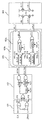
도 2은 본 발명에 따른 캡슐 내시경과 외부 유닛의 송수신 시스템의 일례를 설명하기 위한 도.
도 3는 본 발명에 따른 캡슐 내시경의 초광대역 송신기에 포함된 초광대역(UWB) 펄스 생성기의 일례를 설명하기 위한 도,
도 4는 초광대역(UWB) 펄스 생성기를 구동하기 위한 타이밍도의 일례.
도 5는 이와 같은 미세 딜레이부와 제 1, 2 거시 딜레이부 및 각 딜레이부의 바이어스 회로의 일례.
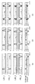
도 6는 H브리지 제어 블록에서 출력된 제어 신호에 따라 H브리지에서 출력되는 가우시안 펄스의 예를 나타내는 도,
도 7는 도 6의 펄스를 실제로 측정한 그래프.
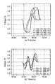
도 8는 1차와 5차 미분된 가우시안 펄스에 대한 제어능력을 설명하기 위한 도.
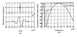
도 9은 б=65ns 와 750ns의 표준 미분을 갖는 5차 미분 가우시안 펄스.
도 10 및 도 11는 외부 유닛에 포함되는 초광대역(UWB) 수신기의 일례를 설명하기 위한 도.
도 12은 본 발명에 따른 초광대역 수신기의 주파수 특성.
이하, 본 발명의 바람직한 실시예를 첨부된 도면들을 참조하여 상세히 설명한다.
우선 각 도면의 구성 요소들에 참조 부호를 부가함에 있어서, 동일한 구성 요소들에 대해서는 비록 다른 도면상에 표시되더라도 가능한 한 동일한 부호를 가지도록 하고 있음에 유의해야 한다. 또한, 본 발명을 설명함에 있어, 관련된 공지 구성 또는 기능에 대한 구체적인 설명이 본 발명의 요지를 흐릴 수 있다고 판단되는 경우에는 그 상세한 설명은 생략한다. 또한, 이하에서 본 발명의 바람직한 실시예를 설명할 것이나, 본 발명의 기술적 사상은 이에 한정하거나 제한되지 않고 당업자에 의해 변형되어 다양하게 실시될 수 있음은 물론이다.
이하, 본 발명의 실시예를 첨부된 도면을 참조하여 상세히 설명하고자 한다.
도 1는 본 발명에 따른 무선 내시경 시스템의 전체 개념을 설명하기 위한 도이다.
도시된 바와 같이 본 발명에 따른 무선 내시경 시스템은 캡슐 내시경과 외부 유닛을 포함한다.
캡슐 내시경은 인체 내부로 삽입되어 장기 내부의 상태를 영상으로 촬영하여 외부 유닛으로 촬영된 영상 신호를 전송하는 기능을 한다.
이와 같은 캡슐 내시경은 외부 유닛으로부터 캡슐 내시경을 구동하기 위한 제어 신호인 웨이크 업(Wake Up) 신호와 캡슐 내시경의 위치 제어를 위한 제어 신호를 전송받거나 촬영된 영상 신호를 외부 유닛으로 전송하기 위한 원형 안테나와 송수신기를 포함한다.
이와 같이 외부 유닛으로부터 웨이크 업(Wake Up) 신호를 전송받으면 시스템 제어부는 조명 LED, 렌즈, CMOS를 포함하는 캡슐 내시경의 영상 신호 획득부가 제어 신호인 웨이크 업(Wake Up) 신호에 따라 장기 내부의 상태를 영상으로 촬영하여 영상 신호를 획득하도록 제어한다.
이와 같이 획득된 영상 신호는 송수신기와 원형 안테나를 통하여 외부 유닛으로 전송된다.
여기서, 캡슐 내시경의 수신기는 ISM(Industrial Scientic and Medical) band의 제어 신호를 전송받아 구동하는 협대역 수동 수신기(Narrowband Passive Receiver; LDR)를 포함하고, 송신기는 인체 내부의 장기 상태를 영상으로 촬영하여 획득된 영상 신호와 국부 발진 신호를 입력받아 초광대역(Ultra Wide Band; UWB)에 속하는 가우시안 펄스, 1차 미분 가우시안 펄스 또는 5차 미분 가우시안 펄스 중 어느 하나의 가우시안 펄스를 선택적으로 생성함으로써, 획득된 영상 신호를 초광대역(UWB)의 영상 신호로 변조하여 전송하는 초광대역(UWB) 펄스 생성기(Pulse Generator);를 포함하는 초광대역 송신기(UWB transmitter)를 포함한다.
외부 유닛은 캡슐 내시경을 동작시키고, 촬영된 영상을 수신하여 영상을 구현하는 기능을 한다. 이와 같은 외부 유닛은 ISM(Industrial Scientic and Medical) 주파수 대역에서 구동하는 협대역 송신기(미도시) 및 초광대역(Ultra Wide Band; UWB) 주파수 대역에서 구동하는 초광대역 수신기(미도시)를 포함한다.
이와 같은 위부 유닛의 협대역 송신기는 캡슐 내시경을 구동하기 위해 ISM(Industrial Scientic and Medical) 대역의 제어 신호로서, 인체 내부에 있는 캡슐 내시경으로 캡슐 내시경을 구동하기 위한 웨이크 업(Wake Up)신호와 캡슐 내시경의 위치제어를 위한 제어 신호를 생성하여 갭슐 내시경의 협대역 수동 수신기로 전송하는 기능을 하고, 초광대역 수신기는 캡슐 내시경의 초광대역 송신기로부터 초광대역(UWB)의 영상 신호를 수신받아 신호처리하는 기능을 한다.
이와 같은 무선 내시경 시스템의 구성에 대해 보다 상세히 살펴보면 다음과 같다.
도 2은 본 발명에 따른 캡슐 내시경과 외부 유닛의 송수신 시스템의 일례를 설명하기 위한 도이다.
도시된 바와 같이, 본 발명의 일례에 따른 무선 내시경 시스템은 갭슐 내시경과 외부 유닛을 포함하고, 캡슐 내시경은 협대역 수동 수신기(300) 및 초광대역(UWB) 송신기(400)를 포함하고, 외부 유닛은 협대역 송신기(700) 및 초광대역(UWB) 수신기(800)를 포함한다.
도시된 바와 같이, 캡슐 내시경은 안테나(100), 선택부(200), 협대역 수동 수신기(300), 초광대역(UWB) 송신기(400)를 포함한다.
안테나(100)는 외부 유닛으로부터 전송되는 제어 신호인 웨이크 업(Wake Up)신호 및 캡슐 내시경의 위치제어를 위한 신호를 수신하거나 캡슐 내시경으로부터 생성된 초광대역 영상 신호를 전송하는 기능을 한다.
선택부(200)는 외부 유닛의 협대역 송신기(700)로부터 전송되는 제어 신호인 웨이크 업(Wake Up) 신호 및 캡슐 내시경의 위치 제어 신호를 수신하기 위해 안테나(100)와 협대역 수동 수신기(300)를 전기적으로 연결하는 기능을 하거나, 캡슐 내시경으로부터 생성된 초광대역 영상 신호를 외부 유닛의 초광대역 수신기로 전송하기 위해 초광대역(UWB) 송신기(400)와 안테나(100)를 전기적으로 연결하는 기능을 한다.
협대역 수동 수신기(300)는 외부 유닛으로부터 전송된 ISM(Industrial Scientic and Medical) 대역의 제어 신호인 웨이크 업(Wake Up) 신호를 수신하여 영상 신호 획득부를 구동하기 위한 신호로 변조하는 기능을 한다.
이와 같은 협대역 수동 수신기(300)는 저잡음 증폭기(LNA, 310), 혼합부(320), 적분기(330), 위상 동기부(340) 및 디시젼 디텍터(350)(Decision Detector)를 포함할 수 있다.
저잡음 증폭기(LNA, 310)는 외부 유닛의 협대역 송신기(700)로부터 전송된 ISM band의 제어 신호를 증폭시키는 기능을 한다.
혼합부(320)는 증폭된 제어 신호와 협대역 수동 수신기(300)의 출력단으로부터 피드백된 신호가 동기화된 신호를 합성하여 증폭된 제어 신호를 변조하는 기능을 한다.
여기서, 혼합부(320)에 동기화된 신호를 입력하기 위해 협대역 수동 수신기(300)의 출력단으로부터 피드백된 신호를 미리 결정된 주파수에 동기시키는 기능은 위상 동기부(340)에 의해 수행된다.
적분기(330)는 혼합부(320)로부터 복조된 제어 신호에 대해 적분 회로 기능을 수행하는 기능을 한다.
이후, 변조된 제어 신호는 디시젼 디텍터(350)(Decision Detector)를 통하여 캡슐 내시경의 시스템 제어부(미도시)로 출력된다.
이후, 영상 신호 획득부(미도시)가 제어 신호에 따라 인체 내부 장기의 상태를 영상으로 촬영하여 영상 신호를 획득하면, 초광대역(UWB) 송신기(400)는 획득된 영상 신호를 입력받아 외부 유닛으로 3.1GHz 내지 5GHz의 초광대역(Ultra Wide Band; UWB) 주파수 대역의 영상 신호를 생성하여 외부 유닛으로 송신하는 기능을 한다.
이와 같은 초광대역(UWB) 송신기(400)는 XOR 게이트(410), 초광대역(UWB) 펄스 생성기(420)(Pulse Generator; PG), 시간 지연부(430), 국부 발진기(440)를 포함할 수 있다.
XOR 게이트(410)로는 입력단으로 획득된 영상 신호와 출력단으로부터 피드백된 신호가 국부 발진기(440)로부터 생성된 클럭 신호에 따라 지연된 신호가 입력된다.
이와 같이 XOR 게이트(410)를 통과한 영상 신호는 초광대역(UWB) 펄스 생성기(420)를 통하여 초광대역(UWB) 주파수 대역의 영상신호로 변조된다. 이와 같은 초광대역(UWB) 펄스 생성기(420)는 하나의 칩에 집적 가능하며, 인체 내부의 장기 상태를 영상으로 촬영하여 획득된 영상 신호와 국부 발진 신호를 입력받아 초광대역(Ultra Wide Band; UWB)에 속하는 가우시안 펄스, 1차 미분 가우시안 펄스 또는 5차 미분 가우시안 펄스 중 어느 하나의 가우시안 펄스를 선택적으로 생성함으로써, 획득된 영상 신호를 초광대역(UWB)의 영상 신호로 변조하여 전송하는 기능을 한다. 여기서, 초광대역(UWB) 펄스 생성기(420)에 대한 보다 상세한 설명은 후술한다.
다음, 외부 유닛은 적어도 하나 이상의 안테나(500), 선택부(MUX, 600), 협대역 송신기(700) 및 초광대역(UWB) 수신기(800)를 포함한다.
안테나(500)는 인체 내부로 삽입되어 장기 내부의 상태를 영상으로 촬영하는 캡슐 내시경을 제어하기 위한 제어 신호를 송신하거나 캡슐 내시경으로부터 전송되는 영상 신호를 수신하는 기능을 한다.
선택부(MUX, 600)는 제어 신호를 캡슐 내시경으로 송신하기 위하여 송신기와 적어도 하나 이상의 안테나(500)를 전기적으로 연결하거나 영상 신호를 수신하기 위하여 수신기와 적어도 하나 이상의 안테나(500)를 전기적으로 연결하는 기능을 한다.
협대역 송신기(700)는 캡슐 내시경을 구동하기 위해 ISM(Industrial Scientic and Medical) 대역의 제어 신호를 생성하여 협대역 수동 수신기(300)로 전송하는 기능을 한다. 여기서, 제어 신호는 캡슐 내시경을 구동하기 위해 캡슐 내시경을 동작 또는 정지를 제어하는 웨이크 업(Wake Up)신호 및 캡슐 내시경의 위치제어를 위한 제어 신호를 의미한다. 이와 같은 웨이크 업(Wake Up)신호 및 캡슐 내시경의 위치제어를 위한 제어 신호는 큰 부피의 데이터 양을 요구하지 아니하므로 고속의 데이터 전송을 요구하지 아니한다. 따라서, 협대역 송신기(700)의 부피를 증가시키는 요인이 되지 아니한다.
이와 같은 협대역 송신기(700)는 변조부(710) 및 펄스 생성기(720)(Pulse Generation)를 포함한다.
협대역 송신기(700)의 변조부(710)는 무선 내시경 시스템의 내부에서 전송되는 제어 신호를 변조하는 기능을 하고, 펄스 생성기(720)(Pulse Generation)는 변조된 제어 신호를 수신받아 캡슐 내시경이 수신받아 제어될 수 있는 ISM(Industrial Scientic and Medical) 대역의 펄스를 생성하는 기능을 한다.
초광대역(UWB) 수신기(800)는 디지털 신호 처리를 위해 캡슐 내시경의 초광대역(UWB) 송신기(400)로부터 수신된 초광대역(UWB) 영상 신호를 신호 처리를 위해 저대역의 영상 신호로 변조하는 기능을 한다. 이와 같은 초광대역(UWB) 수신기(800)에 대한 보다 상세한 설명은 후술한다.
이와 같이 캡슐 내시경에 포함된 초광대역(UWB) 송신기(400)와 외부 유닛에 포함된 초광대역(UWB) 수신기(800) 사이의 초광대역 통신 방식은 고속 데이터 전송(전송속도 100Mbps에서 5.4mW 전력을 소비하여 한 펄스를 전송하는데 소모되는 에너지는 27pJ/pulse로 초저전력이 소비된다), 저전력 소모(송신기: 5.4mW)가 가능하게 한다.
또한, 초광대역(UWB) 통신 방식에 의한 고속 데이터 전송은 고화질 VGA급 (640x480=307,200화소 수)의 영상 신호 전송이 가능하도록 하여 고화질의 영상을 이미지 압축 없이 보낼 수 있는 효과가 있다. 따라서 종래의 캡슐 내시경에 포함되었던 영상 압축기와 영상 처리 프로 세서가 더 이상 필요하지 않아 본 발명은 캡슐 내시경의 부피를 상대적으로 줄일 수 있다.
또한, 기존의 송수신기 시스템보다 상대적으로 초광대역(UWB) 고주파수에서 동작하므로 안테나(500)와 전자부품들의 소형화가 가능하다.
또한, 캡슐 내시경의 초광대역 송신기에 포함되는 초광대역(UWB) 통신용 펄스 생성기(420)를 디지털로 구현함으로써 하나의 칩에 집적하기가 용이하여 캡슐 내시경의 부피를 줄일 수 있는 효과가 있다.
또한, 캡슐 내시경은 영상 신호를 외부 유닛으로 전송하기 위해 초광대역(UWB) 펄스 생성기(420)에서 가우시안 펄스, 1차 미분 가우시안 펄스 또는 5차 미분 가우시안 펄스 중 선택되어 생성된 어느 하나의 가우시안 펄스를 사용함으로써, 대역통과 필터나 전력 증폭기를 사용하지 않고도 미국연방통신위원회(Federal Communication Commission; FCC)에 의해 규정된 송신 신호의 전력 스펙트럼 밀도제한 마스크를 만족시킬 수 있다. 따라서 본 발명에 따른 캡슐 내시경은 저 전력, 소형화가 가능한 효과가 있다.
도 3는 본 발명에 따른 캡슐 내시경의 초광대역 송신기에 포함된 초광대역(UWB) 펄스 생성기의 일례이고, 도 4는 초광대역(UWB) 펄스 생성기를 구동하기 위한 타이밍도의 일례이다.
도 3 도시된 바와 같이 초광대역(UWB) 펄스 생성기(PG, 420)는 포지티브/네거티브 시그널(pos/neg_sig) 생성부(421), 펄스/디펄스(pulse/d_pulse) 생성부(422), H브리지 제어 블록(423), H브리지(424)를 포함할 수 있다.
포지티브/네거티브 시그널(pos/neg_sig) 생성부(421)는 XOR 게이트(410)의 출력단으로부터 입력된 영상 신호(Data, Data_bar)와 국부 발진기로부터 생성된 클록 신호(Clk)에 따라 영상 신호의 데이터 비트를 식별하여 포지티브 시그널(pos_sig)과 네거티브 시그널(neg_sig)을 생성하는 기능을 한다.
여기서, 포지티브 시그널(pos_sig)과 네거티브 시그널(neg_sig)은 가우시안 펄스를 생성하기 위한 제어 신호인 하이투로우(High to low;H2L) 및 하이투로우(High to low;H2L)와 동기되는 로우투하이(Low to high;L2H) 펄스를 생성하기 위한 제어 신호로 포지티브 시그널(pos_sig)은 영상 신호의 데이터가 "1"인 경우를 나타내고, 네거티브 시그널(neg_sig)은 영상 신호의 데이터가 "0"인 경우를 나타낸다.
이와 같은 포지티브/네거티브 시그널(pos/neg_sig) 생성부(421)는 하나의 NOT 게이트와 두 개의 NOR 게이트를 통해, 도 4에 도시된 바와 같이 영상 신호의 데이터 신호(Data)가 "1", 클록 신호가 "0"일 때 포지티브 시그널(pos_sig)을 생성하고, 영상 신호의 데이터 신호가 "0", 클록 신호가 "0"일 때, 즉 NOR 게이트를 통과한 Data_bar 신호가 "1", 클럭 신호가 "0"일 때, 네거티브 시그널(neg_sig)을 생성할 수 있다.
펄스/디펄스(pulse/d_pulse) 생성부(422)는 도 3와 같이 하나의 XOR 게이트, 두 개의 병렬 NAND 게이트, 제 1 거시 딜레이부(Coarse Delay)(CDE1) 및 각 NAND 게이트의 입력단에 배치된 미세 딜레이부(FDE)(Fine Delay)를 포함한다. 이와 같은 펄스/디펄스(pulse/d_pulse) 생성부(422)는 포지티브/네거티브 시그널(pos/neg_sig)을 입력받아 두 개의 병렬 NAND 게이트를 통하여 하이투로우(High to low) 및 로우투하이(Low to high) 펄스를 생성하기 위한 펄스(pulse) 신호와 펄스 신호(pulse)보다 지연된 디펄스(d_pulse) 신호를 생성하는 기능을 한다.
여기서, XOR 게이트는 도 4와 같이 포지티브/네거티브 시그널(pos/neg_sig) 생성부(421)에서 출력된 포지티브 시그널(pos_sig)과 네거티브 시그널(neg_sig)을 병합하여 After_Xor 신호를 출력한다.
미세 딜레이부(FDE)는 병렬 NAND 게이트 각각의 입력단 일측에 배치되어, 도 4와 같이 입력단 일측으로 입력되는 신호를 fd 만큼 지연한 FDE_Out 신호를 생성함으로써 펄스/디펄스(pulse/d_pulse) 신호 각각의 폭(Width;w)을 제어하는 기능을 한다. 이와 같은 미세 딜레이부(FDE)는 펄스 신호(pulse) 및 디펄스 신호(d_pulse) 각각의 폭(Width;w)을 조절하여 H브리지 제어 블록(423)에서 출력되는 하이투로우(High to low;H2L) 및 로우투하이(Low to high;L2H) 펄스 각각의 폭(w)을 조절함으로써 가우시안 펄스, 1차 미분 가우시안 펄스 또는 5차 미분 가우시안 펄스 중 어느 하나의 가우시안 펄스를 선택적으로 생성하기 위하여 펄스의 폭(Width), 중심 주파수(fc) 및 크기(Amplitude)를 제어할 수 있다.
제 1 거시 딜레이(CDE1)는 두 개의 병렬 NAND 게이트 중 하나의 병렬 NAND 게이트로 입력되는 신호를 d1만큼 지연시키는 기능을 한다. 이와 같이 함으로써 제 1 거시 딜레이(CDE1)는 도 4와 같이 펄스/디펄스(pulse/d_pulse) 생성부(422)의 출력 신호인 펄스 신호(pulse)와 디펄스 신호(d_pulse) 사이의 지연 시간(d1)을 제어할 수 있다. 이와 같이 함으로써, 제 1 거시 딜레이(CDE1)는 H브리지 제어 블록(423)의 제 1 제어블록(422a)에서 출력되는 하이투로우(High to low;H2L) 및 로우투하이(Low to high;L2H) 펄스와 제 2 제어블록(422b)에서 출력되는 하이투로우(High to low;H2L) 및 로우투하이(Low to high;L2H) 펄스의 시간 지연(d1) 차이를 조절할 수 있어, 가우시안 펄스, 1차 미분 가우시안 펄스 또는 5차 미분 가우시안 펄스 중 어느 하나의 가우시안 펄스를 선택적으로 생성하기 위하여 펄스의 폭(Width), 중심 주파수 및 크기(Amplitude)를 제어할 수 있다.
이와 같이, 전술한 미세 딜레이부(FDE)와 제 1 거시 딜레이(CDE1) 및 후술할 제 2 거시 딜레이(CDE2)는 펄스/디펄스(pulse/d_pulse) 신호의 폭(Width)과 지연 시간을 조절하여 가우시안 펄스, 1차 미분 가우시안 펄스 또는 5차 미분 가우시안 펄스 중 어느 하나의 가우시안 펄스를 선택적으로 생성하기 위하여 펄스의 폭(Width), 중심 주파수 및 크기(Amplitude)를 제어하는 기능을 하는 것이다.
따라서, H브리지의 출력 펄스가 가우시안 펄스, 1차 미분 가우시안 펄스가 되도록 할 수도 있고, 5차 미분 가우시안 펄스가 되도록 할 수도 있는 것이다.
도 5는 이와 같은 미세 딜레이부와 제 1, 2 거시 딜레이부 및 각 딜레이부의 바이어스 회로의 일례를 도시한 것이다.
도 5의 (a)는 미세 딜레이부(FDE)의 일례, (b)는 제 1, 2 거시 딜레이부의 일례, (c)는 각각의 딜레이부(FDE, CDE1,2)에 대한 바이어스 회로이다.
도 5에 (a) 및 (b)에 도시된 각각의 딜레이부(FDE, CDE1,2)는 d_in을 통하여 신호를 입력받고, d_out을 통하여 딜레이된 신호를 출력한다.
병렬 NAND 게이트 각각은 도 4와 같이, XOR 게이트의 출력신호(After_Xor)(또는 제 1 거시 딜레이(CDE1)의 출력신호)와 미세 딜레이부(FDE)의 출력신호(FDE_Out)가 모두 On 상태인 경우, 좁은 폭(w)의 펄스(pulse) 신호와 펄스 신호(pulse)보다 d1만큼 지연된 디펄스(d_pulse) 신호를 출력한다.
H브리지 제어 블록(423)은 펄스/디펄스(pulse/d_pulse) 생성부(422)에서 출력된 펄스/디펄스 신호(pulse/d_pulse) 중 하나를 포지티브/네거티브 시그널(pos/neg_sig)의 제어에 따라 복수 개의 멀티플렉서(Multiplexer; Mux)를 통하여 선택하여 입력되도록 하고, 선택하여 입력된 신호(MUX_out)와 선택하여 입력된 신호보다 지연된 딜레이 신호(CDE2_out)가 각각 병합된 하이투로우(High to low) 펄스 및 로우투하이(Low to high) 펄스 쌍을 생성하는 기능을 한다.
이와 같은 H브리지 제어 블록(423)은 이중적 구조의 제 1 제어블록(422a)과 제 2 제어블록(422b)을 포함하고, 제 1 제어블록(422a)과 제 2 제어블록(422b) 각각은 각각 두 개의 복수 개의 멀티플렉서(MUX), 제 2 거시 딜레이(CDE2), XOR 게이트 및 NOT 게이트가 동일하게 배치된다.
복수 개의 멀티플렉서(Mux)는 포지티브/네거티브 시그널(pos/neg_sig) 각각의 제어에 따라 펄스/디펄스(pulse/d_pulse) 신호 중 하나를 선택하여 입력되도록 한다. 이와 같은 복수 개의 멀티플렉서(Mux)는 제 1 제어블록(422a)과 제 2 제어블록(422b)의 복수 개의 멀티플렉서(MUX)로 입력되는 포지티스 시그널(pos_sig)과 네거티브 시그널(neg_sig)의 위치는 서로 바뀌어 입력되도록 샛팅된다.
따라서, 제 1 제어블록(422a)에서 복수 개의 멀티플렉서(Mux)가 입력 데이터(MUX_out)로 펄스(pulse) 시그널을 선택하면, 제 2 제어블록(422b)에서 복수 개의 멀티플렉서(Mux)는 역으로, 디-펄스(d_pulse) 시그널을 선택하게 된다.
여기서, 제 1 제어블록(422a)으로부터 출력되는 하이투로우(H2L_1) 펄스 및 로우투하이(L2H_1) 펄스와 제 2 제어블록(422b)으로부터 출력되는 하이투로우(H2L_2) 펄스 및 로우투하이(L2H_2) 펄스 사이에 지연되는 시간(d1)은 제 1 거시 딜레이(CDE1)에 의해 제어될 수 있다.
따라서, 제 1 거시 딜레이(CDE1)가 펄스(pulse) 시그널과 디-펄스(d_pulse) 시그널 사이의 지연 시간(d1)을 길게 하면, 제 1 제어블록(422a)으로부터 출력되는하이투로우(H2L_1) 펄스 및 로우투하이(L2H_1) 펄스와 제 2 제어블록(422b)으로부터 출력되는 하이투로우(H2L_2) 펄스 및 로우투하이(L2H_2) 펄스 사이에 지연되는 시간(d1)도 길어지게 된다.
제 2 거시 딜레이(CDE2)는 도 4와 같이 입력된 신호(MUX_out)와 선택된 신호보다 지연된 딜레이 신호(CDE2_out) 사이의 지연 시간(d2)을 제어하는 기능을 한다.
이와 같이 제 2 거시 딜레이(CDE2)가 입력된 신호(MUX_out)와 딜레이 신호(CDE2_out) 사이의 지연 시간(d2)을 제어함으로써, H브리지 제어 블록(423)에서 출력되는 하이투로우(H2L) 및 로우투하이(L2H) 신호 각각의 사이 간격을 조절할 수 있다. 따라서 제 2 거시 딜레이(CDE2)가 지연 시간(d2)을 매우 길게 제어하여 하이투로우(H2L) 및 로우투하이(L2H) 신호 각각의 사이 시간 간격(d2)이 벌어지도록 하여 각각의 펄스(H2L, L2H)의 개수가 2 개가 되도록 할 수도 있고, 지연 시간(d2)을 매우 짧게 제어하여 신호 각각의 사이 시간 간격(d2)을 없애 각각의 펄스(H2L, L2H)의 개수가 1개가 되도록 할 수도 있다.
H2L, L2H 펄스의 개수가 각각 1개인 경우 H브리지(424)는 1차 미분 가우시안 펄스를 출력하게 되고, H2L, L2H 펄스의 개수가 각각 2개인 경우 H브리지(424)는 5차 미분 가우시안 펄스를 생성하게 된다.
이와 같이 함으로써, 제 2 거시 딜레이(CDE2)는 입력된 신호(MUX_out)와 딜레이 신호(CDE2_out) 사이의 지연 시간(d2)을 제어함으로써 하이투로우(High to low) 및 로우투하이(Low to high) 펄스의 폭(Width)과 개수를 제어할 수 있고, 이를 통하여 가우시안 펄스의 폭(Width), 중심 주파수 및 크기(Amplitude)를 제어할 수 있다.
이와 같은 H브리지 제어 블록(423)은 제 1 제어블록(422a)에서 제 1 하이투로우(H2L_1) 및 제 1 로우투하이(L2H_1) 신호를 출력하도록 하고, 제 2 제어블록(422b)에서 제 2 하이투로우(H2L_2) 및 제 2 로우투하이(L2H_2) 신호를 출력하도록 함으로써, H브리지(424)에서 서로 교차 연결된 PMOS와 NMOS 쌍을 제어하기 위한 두 개의 H2L펄스와 L2H 펄스 셋을 생성한다.
다음, H브리지(424)는 하이투로우(H2L) 및 로우투하이(L2H) 펄스를 제어 신호로 입력받아 교차 커플링된 PMOS와 NMOS 스위칭 소자 쌍을 통하여 가우시안 펄스를 생성하는 기능을 한다.
이와 같은 H 브리지에서 교차 커플링된 PMOS와 NMOS 스위칭 소자 쌍은 제 1 P/NMOS 스위칭 소자 쌍(P1, N1)과 제 2 P/NMOS 스위칭 소자 쌍(P2, N2)을 포함하고, 제 1 P/NMOS 스위칭 소자 쌍(P1, N1)은 제 1 제어블록(422a)으로부터 출력되는 제 1 하이투로우(H2L_1) 및 로우투하이(L2H_1) 펄스에 의해 턴 온(Turn on)되고, 제 2 P/NMOS 스위칭 소자 쌍(P2, N2)은 제 2 제어블록(422b)으로부터 출력되는 제 2 하이투로우(H2L_2) 및 로우투하이(L2H_2) 펄스에 의해 턴 온(Turn on) 된다.
이때, P1과 N1 쌍은 H2L_1과 L2H_1 신호에 의해 통시에 턴 온(Turn on) 된다. 그리고, 나머지 P2와 N2 쌍은 제 1 거시 딜레이(CDE1)에 의해 제어된 타이밍 오프셋 신호인 H2L_2과 L2H_2 신호에 의해 동시에 턴 온(Turn on) 된다.
이와 같이 함으로써 H브리지(424)는 가우시안 펄스를 생성하게 되는 것이다. 보다 상세하게 설명하면 다음과 같다.
도 6는 H브리지 제어 블록에서 출력된 제어 신호에 따라 H브리지에서 출력되는 가우시안 펄스의 예를 나타내는 도이고, 도 7는 도 6의 펄스를 실제로 측정한 그래프이다.
도 6 및 7을 참조하면, (a)에 도시된 바와 같이, 제 1 거시 딜레이(CDE1)가 지연 시간(d1)을 길게 하고, 제 2 거시 딜레이(CDE2)가 지연 시간(d2)을 매우 짧게 하여 H브리지 제어 블록(423)의 제 1 제어블록(422a)에서 L2H_1 및 H2L_1의 제어 신호가 출력되고, 제 2 제어블록(422b)에서 L2H_2 및 H2L_2가 출력될 때, H브리지(424)에서는 L2H_1 및 H2L_1에 따라 P1과 N1 쌍이 턴 온되어 정극성의 가우시안 펄스가 생성되고, L2H_2 및 H2L_2에 따라 P2과 N2 쌍이 턴 온되어 부극성의 가우시안 펄스가 생성된다.
또한, (b)에 도시된 바와 같이, 제 1 거시 딜레이(CDE1)가 지연 시간(d1)을 짧게 하고, 제 2 거시 딜레이(CDE2)가 지연 시간(d2)도 매우 짧게 하여 H브리지 제어 블록(423)의 제 1 제어블록(422a)에서 먼저 L2H_1 및 H2L_1의 제어 신호가 출력되고, 제 2 제어블록(422b)에서 이후에 L2H_2 및 H2L_2가 출력될 때, H브리지(424)에서는 L2H_1 및 H2L_1에 따라 P1과 N1 쌍이 먼저 턴 온되고, L2H_2 및 H2L_2에 따라 P2과 N2 쌍이 나중에 턴 온되어 1차 미분된 가우시안 펄스가 생성된다.
그리고, 이와 반대로, H브리지 제어 블록(423)의 제 2 제어블록(422b)에서 먼저 L2H_2 및 H2L_2의 제어 신호가 출력되고, 제 1 제어블록(422a)에서 이후에 L2H_1 및 H2L_1이 출력될 때, H브리지(424)에서는 L2H_2 및 H2L_2에 따라 P2과 N2 쌍이 먼저 턴 온되고, L2H_2 및 H2L_2에 따라 P2과 N2 쌍이 나중에 턴 온되어 위상이 반전된 1차 미분된 가우시안 펄스가 생성된다.
또한, (c)에 도시된 바와 같이, 제 1 거시 딜레이(CDE1)가 지연 시간(d1)을 짧게 하고, 제 2 거시 딜레이(CDE2)가 지연 시간(d2)을 상대적으로 길게 하고, 미세 딜레이부(FDE)가 지연 시간(w)을 짧게 하여, H브리지(424)에서는 5차 미분된 가우시안 펄스가 생성될 수 있는 것이다.
이와 같이, 본 발명에 따른 초광대역(UWB) 펄스 생성부(PG,420)는 딜레이부들(FDE, CDE1,2)의 바이어스 상태 제어를 통해 펄스 폭과 상대적인 딜레이를 튜닝함으로써 여러 종류의 가우시안 펄스를 생성할 수 있는 것이다.
표 1은 post layout 시뮬레이션을 통하여 획득된 PG 칩의 펄스 특성을 나타낸다.
표 1
| Variable/Pulse | 가우시안 펄스 | 1차 미분 | 5차 미분 |
| Ctl Vol. @ CDE1 | 1.5~1.8V | 0~1.1V | 0~1.0V |
| Ctl Vol. @ CDE2 | 1.2~1.8V | 1.1~1.5V | 0~1.0V |
| H브리지 펄스 폭(Width) | 400~490ps | 500~780ps | 600~900ps |
| H브리지 펄스 크기(Amp) | 130~280mV | 400~600mV | 150~500mV |
| 송신 전력 | 23~40uW | 56~74uW | 29~71uW |
이와 같은 초광대역(UWB) 펄스 생성부(PG,420)는 초당 200메가 펄스(200Mps)의 펄스 반복 주파수(PRF pulse repetion frequency) 및 200Mps에서 5,4mW의 전력 소모하게 된다.
도 8는 1차와 5차 미분된 가우시안 펄스에 대한 제어능력을 보여준다. 이와 같은 제어 능력을 통해 인체에 의한 신호 감쇠 영향에 유용하게 대응할 수 있다.
(a)는 1차 미분된 가우시안 펄스를 나타내고, (b)는 5차 미분된 가우시안 펄스를 나타낸다. (b)와 같이 5차 미분 가우시안 펄스는 도 9에 도시된 바와 같은 FCC 스펙트럼 마스크를 쉽게 만족시킬 수 있다. 도시된 바와 같이 초광대역(UWB) 펄스 생성부(PG,420)는 딜레이부들(FDE, CDE1,2)의 제어 신호를 제어함으로써 전술한 바와 같은 요구를 쉽게 만족시킬 수 있는 것이다.
여기서, 도 9은 б=65ns 와 750ns의 표준 미분을 갖는 5차 미분 가우시안 펄스로서 (a)는 시간 도메인이고, (b)는 전력 스펙트럼 밀도(Power spectral density;PSD)를 나타낸다.
종래의 펄스 생성부는 FCC 스펙트럼 마스크를 만족시키기 위해서는 대역 통과 필터, 수동 소자 및 에너지를 소비하는 전력 증폭기와 같은 추가적인 회로들이 요구한다.
그러나, 본 발명에 따른 초광대역(UWB) 펄스 생성부(PG,420)는 비효율적인 전력 수동 소자로 인한 출력 펄스의 흔들림을 제거하고, 디지털 게이트에서 직접적으로 딜레이 하는 것보다 딜레이부들(FDE, CDE1,2) 사이에서 상대적 딜레이를 이용함으로써 PVT(Process, voltage, temperature) 변화에 비교적 강력한 효과가 있다.
도 10 및 도 11는 외부 유닛에 포함되는 초광대역(UWB) 수신기의 일례를 설명하기 위한 도이다.
도 10에 도시된 바와 같이 외부 유닛에 포함되는 초광대역(UWB) 수신기(800)는 저잡음 증폭기(810)(Low Noise Amplifier;LNA), 제 1, 2 혼합부(821, 822), 제 1, 2 로패스필터(841, 842)(Low Pass Filter), 제 1, 2 복조부(860, 870), 합산부(880), 위상차 발생기(830), 국부 발진기(850)(VCO), 적분기(890), 디지털 변환기(891)(Analog to digital converter;ADC), 위상 고정기(892)(Phase Locked Loop; PLL) 및 타이밍 발생기(893)를 포함할 수 있다.
도 10의 저잡음 증폭기(810)(Low Noise Amplifier;LNA)는 인체 내부로 삽입되어 장기 내부의 상태를 영상으로 촬영하는 캡슐 내시경으로부터 전송된 초광대역(Ultra Wide Band; UWB) 영상 신호를 증폭시켜 제 1 혼합부(821)와 제 2 혼합부(822)에 각각 출력하는 기능을 한다. 이와 같이 저잡음 증폭기(810)는 도 11의 (a)와 같이 증폭된 초광대역(UWB) 영상 신호를 출력하게 된다.
도 10의 국부 발진기(850)(VCO)는 위상 고정기(892)로부터 위상 제어 신호를 전송받아 제어 신호에 따라 제 1 반송파를 생성하는 기능을 한다.
도 10의 위상차 발생기(830)는 국부 발진기(850)로부터 제 1 반송파 신호를 수신하여 차동 위상차를 갖는 제 2 반송파 신호를 생성하고, 제 1 반송파 신호를 I채널로 출력하고 제 2 반송파 신호를 Q채널로 출력하는 기능을 한다.
여기서, 제 1 반송파 신호와 제 2 반송파 신호의 위상 차이는 90°도가 되도록 할 수 있다.
이와 같이 위상차 발생기(830)는 I채널 또는 Q채널로 도 11의 (b)와 같은 제 1 반송파 또는 제 2 반송파 신호를 출력하게 된다.
도 10의 제 1 혼합부(821)와 제 2 혼합부(822)는 증폭된 초광대역(Ultra Wide Band; UWB) 영상 신호에 대해 국부 발진기(850)로부터 생성된 제 1 반송파 신호와 제 2 반송파 신호로 각각 다운 컨버젼(Down-conversion)하여 상기 영상 신호의 포락선을 검출하는 기능을 한다.
이와 같이 제 1 혼합부(821)와 제 2 혼합부(822)는 도 11의 (c)와 같이 포락선이 검출된 영상 신호를 출력하게 된다.
도 10의 제 1 로패스 필터(841)와 제 2 로패스 필터(842)는 포락선이 검출된 각각의 영상 신호에 대해 저대역을 필터링하여 도 11의 (d)와 같이 주파수가 낮은 영상 신호를 출력하게 된다.
도 10의 제 1 복조부(860)와 제 2 복조부(870)는 저대역 필터링된 각각의 영상 신호와 저대역 필터링된 각각의 영상 신호를 지연한 신호를 합성하는 기능을 한다.
여기서, 제 1 복조부(860)와 제 2 복조부(870) 각각은 제 1, 2 딜레이부(861, 871)와 제 1, 2 복조 합성부(862, 872)를 포함한다.
제 1, 2 딜레이부(861, 871)는 저대역 필터링된 각각의 영상 신호를 지연시키는 기능을 하고, 제 1, 2 복조 합성부(862, 872)는 저대역 필터링된 각각의 영상 신호와 각각의 지연된 신호를 합성하여 도 11의 (e)와 같이 복조된 신호를 출력하는 기능을 한다.
종래 경우에는, 수신된 영상 신호를 변조하는 경우, 도 6의 (a)와 같은 신호를 지연시켜 변조하였다. 이와 같은 경우, 주파수가 높아 지연 시간을 정확히 맞추기가 어렵고, 신호의 광대역특성으로 인해, 광대역 지연의 구현이 어려워 복조가 정확히 이루어지지 아니하였다.
그러나, 본 발명과 같이, 차동 위상차를 갖는 반송파 신호를 이용하여 입력된 영상 신호에 대해 각각 다운 컨버젼(Down-conversion)하여 포락선을 검출한 후, 저대역 필터링된 도 6의 (d)와 같은 영상 신호에 대해 변조하는 경우, 영상 신호의 주파수가 상대적으로 낮아 변조를 위한 지연 시간을 맞추는 것이 상대적으로 용이하여 본 발명의 초광대역(UWB) 수신기(800)는 변조를 보다 정확히 할 수 있는 효과가 있다.
도 10의 합산부(880)는 제 1 복조부(860)와 제 2 복조부(870)로부터 출력되는 각각의 영상 신호를 합산하는 기능을 한다.
도 10의 적분기(890)는 합산부(880)로부터 출력된 영상 신호에 대해 적분 회로 기능을 수행하는 기능을 한다.
도 10의 디지털 변환기(891)(Analog to digital converter;ADC)는 적분기(890)로부터 출력되는 영상 신호를 디지털 변환하는 기능을 한다. 이때 디지털 변환기(891)는 타이밍 발생부로부터 타이밍 제어 신호를 전송받아 입력된 아나로그 영상 신호를 디지털 영상 신호로 샘플링(Samppling)하게 된다.
도 10의 위상 고정기(892)(Phase Locked Loop; PLL)는 디지털 변환기(891)로부터 출력되는 영상 신호를 피드백 받아 영상 신호의 위상을 검출하고 위상을 조절하는 위상 제어 신호를 국부 발진기(850)와 타이밍 발생기(893)로 출력하는 기능을 한다.
국부 발진기(850)로 출력된 위상 제어 신호는 국부 발진기(850)에서 생성하는 제 1 반송파의 주파수를 조절하게 된다.
도 10의 타이밍 발생기(893)는 위상 제어 신호를 전송받아 제 1 복조부(860)와 제 2 복조부(870)의 신호 지연 시간을 제어하는 신호 및 디지털 변환기(891)의 디지털 변환 타이밍을 제어하는 신호를 출력하는 기능을 한다.
이와 같이, 본 발명에 따른 외부 유닛에 포함되는 초광대역(UWB) 수신기의 일례는 도 11와 같이 입력된 초고주파 대역인 UWB 대역의 영상 신호에 대해 다운 컨버젼하여 포락선을 검출한 후 저대역 필터링을 하여 저대역 밴드의 영상 신호로 변경한 이후에 신호 합성을 함으로써, 광대역 지연의 문제를 해결할 수 있는 효과가 있다.
도 12은 본 발명에 따른 초광대역 수신기의 주파수 특성을 보여준다.
도시된 바와 같이 본 발명에 따른 초광대역 수신기(800)는 일반적으로 2.1GHz와 5.1GHz에서 나타나는 강한 협대역 간섭이 발생하지 아니하고 제거되는 것을 알 수 있다.
이상의 설명은 본 발명의 기술 사상을 예시적으로 설명한 것에 불과한 것으로서, 본 발명이 속하는 기술 분야에서 통상의 지식을 가진 자라면 본 발명의 본질적인 특성에서 벗어나지 않는 범위 내에서 다양한 수정, 변경 및 치환이 가능할 것이다. 따라서, 본 발명에 개시된 실시예 및 첨부된 도면들은 본 발명의 기술 사상을 한정하기 위한 것이 아니라 설명하기 위한 것이고, 이러한 실시예 및 첨부된 도면에 의하여 본 발명의 기술 사상의 범위가 한정되는 것은 아니다. 본 발명의 보호 범위는 아래의 청구범위에 의하여 해석되어야 하며, 그와 동등한 범위 내에 있는 모든 기술 사상은 본 발명의 권리범위에 포함되는 것으로 해석되어야 할 것이다.
Claims (24)
- 국부 발진 신호를 생성하여 출력하는 국부 발진기; 및하나의 칩에 집적 가능하며, 인체 내부의 장기 상태를 영상으로 촬영하여 획득된 영상 신호와 상기 국부 발진 신호를 입력받아 초광대역(Ultra Wide Band; UWB)에 속하는 가우시안 펄스, 1차 미분 가우시안 펄스 또는 5차 미분 가우시안 펄스 중 어느 하나의 가우시안 펄스를 선택적으로 생성함으로써, 상기 획득된 영상 신호를 초광대역(UWB)의 영상 신호로 변조하여 전송하는 초광대역(UWB) 펄스 생성기(Pulse Generator);를 포함하는 캡슐 내시경의 초광대역 송신기.
- 제 1 항에 있어서,상기 초광대역(UWB) 펄스 생성기는상기 국부발진신호에 의해 생성된 클록 신호에 따라 상기 영상 신호의 데이터 비트를 식별하기 위한 포지티브 시그널(pos_sig) 및 네거티브 시그널(neg_sig)을 생성하는 포지티브/네거티브 시그널 생성부;상기 포지티브 시그널(pos_sig) 및 네거티브 시그널(neg_sig)을 입력받아 두 개의 병렬 NAND 게이트를 통하여 상기 어느 하나의 가우시안 펄스를 생성하기 위한 제어 신호인 하이투로우(High to low) 및 로우투하이(Low to high) 펄스를 생성하기 위한 펄스(pulse) 신호와 상기 펄스(pulse) 신호보다 지연된 디펄스(d_pulse) 신호를 생성하는 펄스/디펄스 생성부;복수 개의 멀티플렉서(Multiplexer; Mux)를 통하여 상기 펄스 신호 및 상기 디펄스 신호 각각을 상기 포지티브 및 네거티브 시그널 각각의 제어에 따라 선택하여 입력되도록 하고, 상기 선택하여 입력된 신호와 상기 선택하여 입력된 신호보다 지연된 딜레이 신호가 병합된 상기 하이투로우(High to low) 펄스 및 로우투하이(Low to high) 펄스 쌍을 생성하는 H브리지 제어 블록; 및상기 하이투로우(High to low) 및 로우투하이(Low to high) 펄스 쌍을 제어 신호로 입력받아 교차 커플링된 PMOS와 NMOS 스위칭 소자 쌍을 통하여 상기 어느 하나의 가우시안 펄스를 생성하는 H브리지;를 더 포함하는 것을 특징으로 하는 캡슐 내시경의 초광대역 송신기.
- 제 2 항에 있어서,상기 펄스/디펄스 생성부는상기 펄스/디펄스 신호 각각의 폭(Width)을 제어하는 미세 딜레이(Fine Delay)부; 및상기 펄스/디펄스 신호 사이의 지연 시간을 제어하는 제 1 거시 딜레이(Coarse Delay)부;를 더 포함하는 것을 특징으로 하는 캡슐 내시경의 초광대역 송신기.
- 제 3 항에 있어서,상기 미세 딜레이부 및 제 1 거시 딜레이부는각각 상기 펄스/디펄스 신호의 폭(Width)과 지연 시간을 조절하여 상기 H브리지를 통하여 상기 어느 하나의 가우시안 펄스를 선택적으로 생성하기 위하여 펄스의 폭(Width), 중심 주파수 및 크기(Amplitude)를 제어하는 것을 특징으로 하는 캡슐 내시경의 초광대역 송신기.
- 제 3 항에 있어서,상기 미세 딜레이부 및 제 1 거시 딜레이부는각각 상기 펄스/디펄스 신호의 폭(Width)과 지연 시간을 조절하여 상기 H브리지가 출력하는 상기 어느 하나의 가우시안 펄스는 상기 가우시안 펄스, 1차 또는 5차 미분된 가우시안 펄스 중 어느 하나가 되도록 하는 것을 특징으로 하는 캡슐 내시경의 초광대역 송신기.
- 제 3 항에 있어서,상기 H브리지 제어 블록은상기 입력된 신호와 상기 선택된 신호보다 지연된 딜레이 신호 사이의 지연 시간을 제어하는 제 2 거시 딜레이부;를 더 포함하는 것을 특징으로 하는 캡슐 내시경의 초광대역 송신기.
- 제 6 항에 있어서,상기 H브리지 제어 블록은 이중적 구조의 제 1 제어블록과 제 2 제어블록을 포함하고,상기 제 1 제어 블록과 제 2 제어 블록 각각은 서로 동일한 구조를 지니고, 상기 제 1 제어 블록과 제 2 제어 블록에 포함된 상기 복수 개의 멀티플렉서(Multiplexer; Mux)를 통하여 선택되어 입력되는 상기 포지티브/네거티브 시그널의 위치가 서로 반대되는 것을 특징으로 하는 캡슐 내시경의 초광대역 송신기.
- 제 7 항에 있어서,상기 제 1 제어 블록이 상기 펄스 신호를 선택하는 경우, 상기 제 2 블록은 상기 디펄스 신호를 선택하도록 상기 제 1, 2 제어 블록이 샛팅(setting)되는 것을 특징으로 하는 캡슐 내시경의 초광대역 송신기.
- 제 8 항에 있어서,상기 제 1 제어 블록으로부터 출력되는 상기 하이투로우(High to low) 펄스 및 로우투하이(Low to high) 펄스와 상기 제 2 제어 블록으로부터 출력되는 상기 하이투로우(High to low) 펄스 및 로우투하이(Low to high) 펄스 사이에 지연되는 시간은 상기 펄스/디펄스 생성부에 포함되는 제 1 거시 딜레이부에 의해 제어되는 것을 특징으로 하는 캡슐 내시경의 초광대역 송신기.
- 제 7 항에 있어서,상기 H 브리지에서 교차 커플링된 PMOS와 NMOS 스위칭 소자 쌍은 제 1 P/NMOS 스위칭 소자 쌍과 제 2 P/NMOS 스위칭 소자 쌍을 포함하고,상기 제 1 P/NMOS 스위칭 소자 쌍은 상기 제 1 제어 블록으로부터 출력되는 상기 하이투로우(High to low) 펄스 및 로우투하이(Low to high) 펄스에 의해 턴 온(Turn on)되고,상기 제 2 P/NMOS 스위칭 소자 쌍은 상기 제 2 제어 블록으로부터 출력되는 상기 하이투로우(High to low) 펄스 및 로우투하이(Low to high) 펄스에 의해 턴 온(Turn on)되는 것을 특징으로 하는 캡슐 내시경의 초광대역 송신기.
- 인체 내부 장기의 상태를 영상으로 촬영하여 영상 신호를 획득하도록 하기 위해 ISM(Industrial Scientic and Medical) 대역의 제어 신호를 전송받는 협대역 수동 수신기(Narrowband Passive Receiver); 및상기 제어 신호에 따라 촬영하여 획득된 영상 신호를 입력받아 상기 획득된 영상 신호를 초광대역(UWB)의 영상 신호로 변조하여 전송하기 위한 상기 제 1 항 내지 제 10 항에 따른 캡슐 내시경의 초광대역 송신기;를 포함하는 캡슐 내시경.
- 인체 내부 장기의 상태를 영상으로 촬영하여 영상 신호를 획득하도록 하기 위해 ISM(Industrial Scientic and Medical) 대역의 제어 신호를 전송받는 협대역 수동 수신기; 및하나의 칩에 집적 가능하며, 상기 제어 신호에 따라 촬영하여 획득된 영상 신호를 입력받아 초광대역(Ultra Wide Band; UWB)에 속하는 가우시안 펄스, 1차 미분 가우시안 펄스 또는 5차 미분 가우시안 펄스 중 어느 하나의 가우시안 펄스를 선택적으로 생성함으로써, 상기 획득된 영상 신호를 초광대역(UWB)의 영상 신호로 변조하여 전송하는 초광대역(UWB) 펄스 생성기(Pulse Generator);를 포함하는 캡슐 내시경의 초광대역 송신기;를 포함하는 캡슐 내시경;과상기 캡슐 내시경을 구동하기 위해 상기 ISM(Industrial Scientic and Medical) 대역의 제어 신호를 생성하여 상기 협대역 수동 수신기로 전송하는 협대역 송신기; 및상기 캡슐 내시경의 초광대역 송신기로부터 상기 초광대역(UWB)의 영상 신호를 수신받아 신호처리하는 초광대역 수신기;를 포함하는 외부 유닛;을 포함하는 무선 내시경 시스템.
- 제 12 항에 있어서,상기 외부 유닛의 초광대역 수신기는상기 수신된 초광대역 영상 신호에 대해 제 1 반송파 신호와 상기 제 1 반송파 신호와 차동 위상차을 갖는 제 2 반송파 신호로 각각 다운 컨버젼(Down-conversion)하여 상기 영상 신호의 포락선을 검출하는 제 1, 2 혼합부;상기 포락선 검출된 각각의 영상 신호에 대해 저대역을 필터링하는 제 1, 2 로패스필터(Low Pass Filter);상기 저대역 필터링된 각각의 영상 신호와 상기 저대역 필터링된 각각의 영상 신호를 지연한 신호를 합성하는 제 1, 2 복조부; 및상기 제 1, 2 복조부로부터 출력되는 각각의 영상 신호를 합산하는 합산부;를 포함하는 것을 특징으로 하는 무선 내시경 시스템.
- 제 13 항에 있어서,상기 외부 유닛의 초광대역 수신기는상기 무선 갭슐 내시경으로부터 전송된 영상 신호를 증폭시켜 상기 제 1, 2 혼합부에 각각 출력하는 저잡음 증폭기(Low Noise Amplifier;LNA);를 더 포함하는 것을 특징으로 하는 무선 내시경 시스템.
- 제 13 항에 있어서,상기 외부 유닛의 초광대역 수신기는상기 제 1 반송파 신호를 국부 발진기로부터 수신하여 차동 위상차를 갖는 상기 제 2 반송파 신호를 생성하고, 상기 제 1 반송파 신호와 상기 제 2 반송파 신호를 상기 제 1, 2 혼합부로 출력하는 위상차 발생기;를 더 포함하는 것을 특징으로 하는 무선 내시경 시스템.
- 제 13 항에 있어서,상기 제 1, 2 복조부 각각은상기 저대역 필터링된 각각의 영상 신호를 지연시키는 제 1, 2 딜레이부; 및상기 저대역 필터링된 각각의 영상 신호와 상기 각각의 지연 신호를 합성하는 제 1, 2 복조 합성부;를 더 포함하는 것을 특징으로 하는 무선 내시경 시스템.
- 국부 발진 신호를 생성하여 출력하는 국부발진 출력단계; 및인체 내부의 장기 상태를 영상으로 촬영하여 획득된 영상 신호와 상기 국부 발진 신호를 입력받아 초광대역(Ultra Wide Band; UWB)에 속하는 가우시안 펄스, 1차 미분 가우시안 펄스 또는 5차 미분 가우시안 펄스 중 어느 하나의 가우시안 펄스를 선택적으로 생성함으로써, 상기 획득된 영상 신호를 초광대역(UWB)의 영상 신호로 변조하는 초광대역 영상 신호 변조단계;를 포함하는 캡슐 내시경의 초광대역(UWB) 송신 방법.
- 제 17 항에 있어서,상기 초광대역 영상 신호 변조단계는상기 국부발진신호에 의해 생성된 클록 신호에 따라 상기 영상 신호의 데이터 비트를 식별하기 위한 포지티브 시그널(pos_sig) 및 네거티브 시그널(neg_sig)을 생성하는 단계;상기 포지티브 시그널(pos_sig) 및 네거티브 시그널(neg_sig)을 입력받아 두 개의 병렬 NAND 게이트를 통하여 상기 어느 하나의 가우시안 펄스를 생성하기 위한 제어 신호인 하이투로우(High to low) 및 로우투하이(Low to high) 펄스를 생성하기 위한 펄스(pulse) 신호와 상기 펄스(pulse) 신호보다 지연된 디펄스(d_pulse) 신호를 생성하는 단계;복수 개의 멀티플렉서(Multiplexer; Mux)를 통하여 상기 펄스 신호 및 상기 디펄스 신호 각각을 상기 포지티브 및 네거티브 시그널 각각의 제어에 따라 선택하여 입력되도록 하고, 상기 선택하여 입력된 신호와 상기 선택하여 입력된 신호보다 지연된 딜레이 신호가 병합된 상기 하이투로우(High to low) 펄스 및 로우투하이(Low to high) 펄스 쌍을 생성하는 단계; 및상기 하이투로우(High to low) 및 로우투하이(Low to high) 펄스 쌍을 제어 신호로 입력받아 교차 커플링된 PMOS와 NMOS 스위칭 소자 쌍을 통하여 상기 어느 하나의 가우시안 펄스를 생성하는 단계;를 더 포함하는 것을 특징으로 하는 캡슐 내시경의 초광대역(UWB) 송신 방법.
- 인체 내부 장기의 상태를 영상으로 촬영하여 영상 신호를 획득하도록 하기 위해 ISM(Industrial Scientic and Medical) 대역의 제어 신호를 전송받는 협대역 제어 신호 수신 단계; 및상기 제어 신호에 따라 촬영하여 획득된 영상 신호를 입력받아 상기 획득된 영상 신호를 상기 초광대역(UWB)의 영상 신호로 변조하여 전송하는 제 17 항 내지 제 18 항에 따른 캡슐 내시경의 초광대역 송신 방법;을 포함하는 캡슐 내시경의 송수신 방법.
- 무선 내시경 시스템의 송수신 방법에 있어서,상기 무선 내시경 시스템의 외부 유닛이 인체 내부 장기의 상태를 촬영하도록 캡슐 내시경을 구동하기 위한 ISM(Industrial Scientic and Medical) 대역의 제어 신호를 생성하여 상기 캡슐 내시경으로 전송하는 협대역 제어 신호 송신 단계;상기 무선 내시경 시스템의 캡슐 내시경이 상기 ISM(Industrial Scientic and Medical) 대역의 제어 신호를 전송받는 협대역 제어 신호 수신 단계;상기 무선 내시경 시스템의 캡슐 내시경에 포함되는 초광대역 송신기가 상기 제어 신호에 따라 촬영하여 획득된 영상 신호를 입력받아 초광대역(Ultra Wide Band; UWB)에 속하는 가우시안 펄스, 1차 미분 가우시안 펄스 또는 5차 미분 가우시안 펄스 중 어느 하나의 가우시안 펄스를 선택적으로 생성함으로써, 상기 획득된 영상 신호를 초광대역(UWB)의 영상 신호로 변조하여 송신하는 캡슐 내시경의 초광대역 송신 단계; 및상기 무선 내시경 시스템의 외부 유닛이 상기 초광대역(UWB)의 영상 신호를 수신받아 디지털 신호처리할 수 있도록 변조하는 초광대역 영상 신호 수신 단계;를 포함하는 무선 내시경 시스템의 송수신 방법.
- 제 20 항에 있어서,상기 초광대역 영상 신호 수신 단계는상기 캡슐 내시경의 초광대역 송신기로부터 전송된 초광대역의 영상 신호에 대해 제 1 반송파 신호와 상기 제 1 반송파 신호와 차동 위상차을 갖는 제 2 반송파 신호를 각각 합성하여 업 컨버젼(Up-conversion)하는 업 컨버젼 단계;상기 업 컨버젼된 각각의 영상 신호에 대해 저대역을 필터링하는 저대역 필터링 단계;상기 저대역 필터링된 각각의 영상 신호와 상기 저대역 필터링된 각각의 영상 신호를 지연한 신호를 합성하는 변조 단계; 및상기 변조 단계에서 변조되어 출력되는 각각의 영상 신호를 합산하는 단계;를 포함하는 것을 특징으로 하는 무선 내시경 시스템의 송수신 방법.
- 제 21 항에 있어서,상기 초광대역 영상 신호 수신 단계는상기 업 컨버젼 단계 이전에 상기 무선 갭슐 내시경으로부터 전송된 영상 신호를 증폭시켜 상기 제 1 반송파 신호와 제 2 반송파 신호를 통하여 각각 합성하기 위하여 각각 출력하는 저잡음 증폭 단계;를 포함하는 것을 특징으로 하는 무선 내시경 시스템의 송수신 방법.
- 제 22 항에 있어서,상기 초광대역 영상 신호 수신 단계는상기 제 1 반송파 신호를 국부 발진기로부터 수신하여 차동 위상차를 갖는 상기 제 2 반송파 신호를 생성하고, 상기 제 1 반송파 신호와 상기 제 2 반송파 신호를 각각 출력하는 위상차 발생단계;를 포함하는 것을 특징으로 하는 무선 내시경 시스템의 송수신 방법.
- 제 21 항에 있어서,상기 변조 단계는상기 저대역 필터링된 각각의 영상 신호를 지연시키는 단계; 및상기 저대역 필터링된 각각의 영상 신호와 상기 지연된 각각의 신호를 합성하는 단계;를 포함하는 것을 특징으로 하는 무선 내시경 시스템의 송수신 방법.
Applications Claiming Priority (2)
| Application Number | Priority Date | Filing Date | Title |
|---|---|---|---|
| KR1020090037336A KR101063859B1 (ko) | 2009-04-28 | 2009-04-28 | 무선 내시경 시스템 및 그의 송수신 방법 |
| KR10-2009-0037336 | 2009-04-28 |
Publications (1)
| Publication Number | Publication Date |
|---|---|
| WO2010126203A1 true WO2010126203A1 (ko) | 2010-11-04 |
Family
ID=43032333
Family Applications (1)
| Application Number | Title | Priority Date | Filing Date |
|---|---|---|---|
| PCT/KR2009/004424 Ceased WO2010126203A1 (ko) | 2009-04-28 | 2009-08-07 | 무선 내시경 시스템 및 그의 송수신 방법 |
Country Status (2)
| Country | Link |
|---|---|
| KR (1) | KR101063859B1 (ko) |
| WO (1) | WO2010126203A1 (ko) |
Cited By (1)
| Publication number | Priority date | Publication date | Assignee | Title |
|---|---|---|---|---|
| US11055843B2 (en) | 2017-06-14 | 2021-07-06 | Electronics And Telecommunications Research Institute | Capsule endoscope for determining lesion area and receiving device |
Families Citing this family (7)
| Publication number | Priority date | Publication date | Assignee | Title |
|---|---|---|---|---|
| EP2698925A1 (en) | 2012-08-14 | 2014-02-19 | Samsung Electronics Co., Ltd | Apparatus and method for ultra wideband communication using dual band pass filter |
| KR101646226B1 (ko) | 2014-02-28 | 2016-08-08 | 실리콘알엔디(주) | 초광대역 임펄스 발생기 |
| US11607120B2 (en) | 2018-04-09 | 2023-03-21 | Electronics And Telecommunications Research Institute | Capsule endoscopic receiving device, capsule endoscope system including the same, and operating method of capsule endoscopic receiving device |
| US11298009B2 (en) | 2018-05-03 | 2022-04-12 | Electronics And Telecommunications Research Institute | Electrode selection device for selecting optimal electrodes to communicate with capsule endoscope, and operation method thereof |
| US11478137B2 (en) | 2019-04-08 | 2022-10-25 | Electronics And Telecommunications Research Institute | Capsule endoscope image receiver and capsule endoscope device having the same |
| KR102448927B1 (ko) * | 2019-04-08 | 2022-10-04 | 한국전자통신연구원 | 캡슐 내시경 영상 수신기 및 이를 포함하는 캡슐 내시경 장치 |
| KR102622758B1 (ko) * | 2021-12-17 | 2024-01-11 | 가천대학교 산학협력단 | 캡슐내시경 위치 예측 시스템 및 방법 |
Citations (3)
| Publication number | Priority date | Publication date | Assignee | Title |
|---|---|---|---|---|
| JP2006296971A (ja) * | 2005-04-25 | 2006-11-02 | Olympus Medical Systems Corp | 受信装置 |
| JP2007289697A (ja) * | 2006-04-20 | 2007-11-08 | Karl Storz Endovision Inc | 超広帯域無線光学内視鏡装置 |
| JP2008200188A (ja) * | 2007-02-19 | 2008-09-04 | Rf Chips Technology Inc | 無線送信機 |
-
2009
- 2009-04-28 KR KR1020090037336A patent/KR101063859B1/ko not_active Expired - Fee Related
- 2009-08-07 WO PCT/KR2009/004424 patent/WO2010126203A1/ko not_active Ceased
Patent Citations (3)
| Publication number | Priority date | Publication date | Assignee | Title |
|---|---|---|---|---|
| JP2006296971A (ja) * | 2005-04-25 | 2006-11-02 | Olympus Medical Systems Corp | 受信装置 |
| JP2007289697A (ja) * | 2006-04-20 | 2007-11-08 | Karl Storz Endovision Inc | 超広帯域無線光学内視鏡装置 |
| JP2008200188A (ja) * | 2007-02-19 | 2008-09-04 | Rf Chips Technology Inc | 無線送信機 |
Cited By (2)
| Publication number | Priority date | Publication date | Assignee | Title |
|---|---|---|---|---|
| US11055843B2 (en) | 2017-06-14 | 2021-07-06 | Electronics And Telecommunications Research Institute | Capsule endoscope for determining lesion area and receiving device |
| US11715201B2 (en) | 2017-06-14 | 2023-08-01 | Electronics And Telecommunications Research Institute | Capsule endoscope for determining lesion area and receiving device |
Also Published As
| Publication number | Publication date |
|---|---|
| KR20100118469A (ko) | 2010-11-05 |
| KR101063859B1 (ko) | 2011-09-08 |
Similar Documents
| Publication | Publication Date | Title |
|---|---|---|
| WO2010126203A1 (ko) | 무선 내시경 시스템 및 그의 송수신 방법 | |
| AU783039B2 (en) | A device and system for in vivo imaging | |
| CN103006169A (zh) | 电子内窥镜装置及电子内窥镜系统 | |
| JP2006181021A (ja) | 電子内視鏡装置 | |
| WO2012057475A2 (ko) | 캡슐내시경용 이미지센서의 영상데이터 제어시스템 | |
| JP2000165759A (ja) | 内視鏡撮像装置 | |
| WO2011136489A2 (ko) | 듀얼모드 동작이 가능한 캡슐내시경용 이미지센서 | |
| JP2005319097A (ja) | 送信装置および被検体内導入システム | |
| JP3365801B2 (ja) | 電子内視鏡装置 | |
| AU2008202329B2 (en) | A Device and System for In Vivo Imaging | |
| Ye et al. | A CMOS based image acquisition system for electronic endoscope | |
| JPH04231927A (ja) | 電子内視鏡装置 |
Legal Events
| Date | Code | Title | Description |
|---|---|---|---|
| 121 | Ep: the epo has been informed by wipo that ep was designated in this application |
Ref document number: 09844085 Country of ref document: EP Kind code of ref document: A1 |
|
| NENP | Non-entry into the national phase |
Ref country code: DE |
|
| 122 | Ep: pct application non-entry in european phase |
Ref document number: 09844085 Country of ref document: EP Kind code of ref document: A1 |