WO2010125956A1 - 移動通信システム - Google Patents
移動通信システム Download PDFInfo
- Publication number
- WO2010125956A1 WO2010125956A1 PCT/JP2010/057085 JP2010057085W WO2010125956A1 WO 2010125956 A1 WO2010125956 A1 WO 2010125956A1 JP 2010057085 W JP2010057085 W JP 2010057085W WO 2010125956 A1 WO2010125956 A1 WO 2010125956A1
- Authority
- WO
- WIPO (PCT)
- Prior art keywords
- base station
- radio base
- relay node
- bearer
- radio
- Prior art date
- Legal status (The legal status is an assumption and is not a legal conclusion. Google has not performed a legal analysis and makes no representation as to the accuracy of the status listed.)
- Ceased
Links
Images

Classifications
-
- H—ELECTRICITY
- H04—ELECTRIC COMMUNICATION TECHNIQUE
- H04W—WIRELESS COMMUNICATION NETWORKS
- H04W36/00—Hand-off or reselection arrangements
- H04W36/0005—Control or signalling for completing the hand-off
- H04W36/0011—Control or signalling for completing the hand-off for data sessions of end-to-end connection
- H04W36/0016—Hand-off preparation specially adapted for end-to-end data sessions
-
- H—ELECTRICITY
- H04—ELECTRIC COMMUNICATION TECHNIQUE
- H04W—WIRELESS COMMUNICATION NETWORKS
- H04W36/00—Hand-off or reselection arrangements
- H04W36/0005—Control or signalling for completing the hand-off
- H04W36/0055—Transmission or use of information for re-establishing the radio link
- H04W36/0066—Transmission or use of information for re-establishing the radio link of control information between different types of networks in order to establish a new radio link in the target network
-
- H—ELECTRICITY
- H04—ELECTRIC COMMUNICATION TECHNIQUE
- H04W—WIRELESS COMMUNICATION NETWORKS
- H04W36/00—Hand-off or reselection arrangements
- H04W36/08—Reselecting an access point
-
- H—ELECTRICITY
- H04—ELECTRIC COMMUNICATION TECHNIQUE
- H04W—WIRELESS COMMUNICATION NETWORKS
- H04W36/00—Hand-off or reselection arrangements
- H04W36/16—Performing reselection for specific purposes
- H04W36/22—Performing reselection for specific purposes for handling the traffic
-
- H—ELECTRICITY
- H04—ELECTRIC COMMUNICATION TECHNIQUE
- H04B—TRANSMISSION
- H04B7/00—Radio transmission systems, i.e. using radiation field
- H04B7/24—Radio transmission systems, i.e. using radiation field for communication between two or more posts
- H04B7/26—Radio transmission systems, i.e. using radiation field for communication between two or more posts at least one of which is mobile
- H04B7/2603—Arrangements for wireless physical layer control
- H04B7/2606—Arrangements for base station coverage control, e.g. by using relays in tunnels
-
- H—ELECTRICITY
- H04—ELECTRIC COMMUNICATION TECHNIQUE
- H04W—WIRELESS COMMUNICATION NETWORKS
- H04W36/00—Hand-off or reselection arrangements
- H04W36/16—Performing reselection for specific purposes
- H04W36/18—Performing reselection for specific purposes for allowing seamless reselection, e.g. soft reselection
-
- H—ELECTRICITY
- H04—ELECTRIC COMMUNICATION TECHNIQUE
- H04W—WIRELESS COMMUNICATION NETWORKS
- H04W84/00—Network topologies
- H04W84/02—Hierarchically pre-organised networks, e.g. paging networks, cellular networks, WLAN [Wireless Local Area Network] or WLL [Wireless Local Loop]
- H04W84/04—Large scale networks; Deep hierarchical networks
- H04W84/042—Public Land Mobile systems, e.g. cellular systems
- H04W84/047—Public Land Mobile systems, e.g. cellular systems using dedicated repeater stations
-
- H—ELECTRICITY
- H04—ELECTRIC COMMUNICATION TECHNIQUE
- H04W—WIRELESS COMMUNICATION NETWORKS
- H04W92/00—Interfaces specially adapted for wireless communication networks
- H04W92/16—Interfaces between hierarchically similar devices
- H04W92/20—Interfaces between hierarchically similar devices between access points
Definitions
- the present invention relates to a mobile communication system.
- a handover process of the mobile station UE from the radio base station eNB # 1 to the radio base station eNB # 2 is performed.
- handover processing is performed between the radio base station eNB # 1 and the radio base station eNB # 2 via the X2 bearer set between the radio base station eNB # 1 and the radio base station eNB # 2. It is comprised so that the control signal which concerns on may be transmitted / received.
- the radio base station eNB # 1 and the radio base station # 2 have a network layer 1 (NW L1) function and a network layer 2 (NW L2) as an X2 bearer function for setting up an X2 bearer. It has a function, an IP (Internet Protocol) layer function, and an SCTP (Stream Control Transmission Protocol) layer function.
- NW L1 network layer 1
- NW L2 network layer 2
- IP Internet Protocol
- SCTP Stream Control Transmission Protocol
- a “relay node” having a function similar to that of the radio base station eNB is provided between the mobile station UE and the radio base station eNB.
- RN can be connected.
- the present invention has been made in view of the above-described problems, and an object of the present invention is to provide a mobile communication system that can realize a handover process of a mobile station even when a relay node is connected.
- a first feature of the present invention is a mobile communication system, in which a first relay node and a first radio base station are connected via a radio bearer, and the second relay node and the second radio base station are Connected via a radio bearer, the first radio base station and the second radio base station are connected via a bearer, and a mobile station establishes a radio bearer with the first relay node.
- a radio bearer is set between the first relay node and the first relay node that is set and performing communication via the first relay node and the first radio base station, and the second relay node and the second relay node.
- It is configured to perform a handover process with a second state in which communication is performed via a radio base station, and in the handover process, between the first relay node and the first radio base station.
- Radio bearer of the first radio A control signal related to the handover process is transmitted and received via a bearer between a ground station and the second radio base station and a radio bearer between the second relay node and the second radio base station.
- the first relay node when the first relay node receives a measurement report from the mobile station, the first relay node passes through a radio bearer between the first relay node and the first radio base station.
- the first radio base station is configured to transfer the measurement report to the first radio base station, and the first radio base station is configured to transfer the second state from the first state of the mobile station based on the measurement report.
- a handover request signal notifying that is used as a control signal related to the handover process
- the second radio base station transmits the received handover request signal between the second relay node and the second radio base station. Radio bearer between Through, it may be configured to forward to the second relay node.
- the first relay node when the first relay node decides to start a handover process from the first state to the second state of the mobile station, a handover request signal that notifies the fact Is transmitted to the first radio base station via a radio bearer between the first relay node and the first radio base station as a control signal related to the handover process,
- the first radio base station is configured to transfer the received handover request signal to the second radio base station via a bearer between the first radio base station and the second radio base station.
- the second radio base station transfers the received handover request signal to the second relay node via a radio bearer between the second relay node and the second radio base station. Ni It may be.
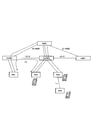
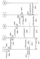
- FIG. 1 is an overall configuration diagram of a mobile communication system according to a first embodiment of the present invention.
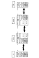
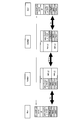
- FIG. 2 is a protocol stack diagram in the mobile communication system according to the first embodiment of the present invention.
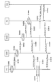
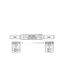
- FIG. 3 is a sequence diagram showing operations of the mobile communication system according to the first embodiment of the present invention.
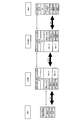
- FIG. 4 is a protocol stack diagram in the mobile communication system according to the second embodiment of the present invention.
- FIG. 5 is a sequence diagram showing operations of the mobile communication system according to the second embodiment of the present invention.
- FIG. 6 is a protocol stack diagram in the mobile communication system according to the third embodiment of the present invention.
- FIG. 7 is a sequence diagram showing operations of the mobile communication system according to the third embodiment of the present invention.
- FIG. 8 is a protocol stack diagram in the current mobile communication system.
- the mobile communication system according to the present invention is an LTE-Advanced mobile communication system, for example, as shown in FIG. 1, to which an exchange MME, relay nodes RN1 to RN4, and a relay node RN1 are connected.
- a radio base station DeNB (Donor eNB) 1 a radio base station DeNB2 to which relay nodes RN2 and RN3 are connected, and a radio base station eNB1 are provided.
- the radio base station DeNB1 and the radio base station DeNB2 are connected via the X2-C interface
- the radio base station DeNB2 and the radio base station eNB1 are connected via the X2-C interface.
- each of the radio base station DeNB1, the radio base station DeNB2, and the radio base station eNB1 is connected to the switching center MME via the S1-MME interface.
- the mobile station UE is configured to perform radio communication by setting a radio bearer between the radio base station eNB (DeNB) and the relay node RN.
- DeNB radio base station eNB
- the mobile station UE sets up a radio bearer with the relay node RN1 (first relay node), and the relay node RN1 and the radio base station DeNB1.
- a radio bearer is set between the state in which communication is performed via the (first radio base station) and the relay node RN2 (second relay node), and the relay node RN2 and the radio base station DeNB2 (second radio base station) )
- the radio bearer (Un interface) between the relay node RN1 and the radio base station DeNB1, the bearer (X2-C interface) between the radio base station DeNB1 and the radio base station DeNB2, and the relay node RN2 A control signal (X2AP signal) related to the handover process is transmitted / received via a radio bearer (Un interface) between the radio base station DeNB2 and the radio base station DeNB2.
- a radio bearer (Un interface) is not set between the relay node RN1 and the relay node RN2.
- the relay node RN1 uses a physical (PHY) as an X2-C radio bearer function for setting up an X2-C radio bearer (Un interface) with the radio base station DeNB1.
- a physical (PHY) as an X2-C radio bearer function for setting up an X2-C radio bearer (Un interface) with the radio base station DeNB1.
- Layer function MAC (Media Access Control) layer function provided as upper layer function of physical (PHY) layer function, and RLC (Radio Link Control) layer function provided as upper layer function of MAC layer function
- PDCP Packet Data Convergence Protocol
- the relay node RN1 may include an RRC (Radio Resource Control) layer function provided as an upper layer function of the PDCP layer function.
- RRC Radio Resource Control
- the relay node RN1 is configured to perform security processing between the relay node RN1 and the radio base station DeNB1 as an upper layer function of the X2-C radio bearer function.
- an SCTP layer function configured to perform keep-alive processing for the X2-C radio bearer as an upper layer function of the IP layer function.
- the relay node RN1 may include an X2AP layer function configured to transmit and receive a control signal related to the handover process as an upper layer function of the SCTP layer function.
- the relay node RN2 has a physical (PHY) layer function and a physical (PHY) as an X2-C radio bearer function for setting an X2-C radio bearer (Un interface) with the radio base station DeNB2.
- MAC layer function provided as an upper layer function of the layer function
- RLC layer function provided as an upper layer function of the MAC layer function
- PDCP layer function provided as an upper layer function of the RLC layer function It has.
- the relay node RN2 may have an RRC layer function provided as an upper layer function of the PDCP layer function.
- the relay node RN2 includes an IP layer function configured to perform security processing between the relay node RN2 and the radio base station DeNB2, as an upper layer function of the X2-C radio bearer function, as an upper layer function, an SCTP layer function configured to perform a keep alive process for the X2-C radio bearer may be provided.
- the relay node RN2 may include an X2AP layer function configured to transmit and receive a control signal related to the handover process as an upper layer function of the SCTP layer function.
- the radio base station DeNB1 also configures an X2-C radio bearer function for setting an X2-C radio bearer (Un interface) with the relay node RN1 and a bearer (X2-C with the radio base station DeNB2).
- a bearer function for setting the interface is also configured.
- the radio base station DeNB1 has a network layer 1 (NW L1) function and a network layer 2 (NW L2) function as bearer functions.
- the radio base station DeNB1 includes an X2-C radio bearer function and an IP layer function provided as an upper layer function of the bearer function, an SCTP function provided as an upper layer function of the IP layer function, and an SCTP layer function.
- X2AP layer function provided as a higher layer function.
- the radio base station DeNB2 configures an X2-C radio bearer function for setting an X2-C radio bearer (Un interface) with the relay node RN2, and a bearer (X2- C bearer function for setting (C interface).
- the radio base station DeNB2 has a network layer 1 (NW L1) function and a network layer 2 (NW L2) function as bearer functions.
- the radio base station DeNB2 includes an X2-C radio bearer function and an IP layer function provided as an upper layer function of the bearer function, an SCTP function provided as an upper layer function of the IP layer function, and an SCTP layer function.
- X2AP layer function provided as a higher layer function.
- the mobile station UE sets up a radio bearer with the relay node RN1, and performs communication via the relay node RN1 and the radio base station DeNB1.
- a description will be given of an operation of performing a handover from a state in which a radio bearer is set to the relay node RN2 to a state in which communication is performed via the relay node RN2 and the radio base station DeNB2.
- the relay node RN1 manages “UE Context” of the mobile station UE in step S1000, and in step S1001, the radio base station DeNB1 via the X2-C radio bearer. Then, the mobile station UE transmits “HO Request (handover request signal)” requesting handover from the relay node RN1 to the relay node RN2.
- HO Request handover request signal
- the radio base station DeNB1 When receiving the “HO Request” in the X2AP layer function, the radio base station DeNB1 stores “UE Context” of the mobile station UE in Step S1002, and in Step S1003, stores the “HO Request” in the X2-C radio. The data is transferred to the radio base station DeNB2 via the bearer.
- the radio base station DeNB2 When receiving the “HO Request” in the X2AP layer function, the radio base station DeNB2 stores “UE Context” of the mobile station UE in Step S1004, and in Step S1005, stores the “HO Request” in the X2-C radio. The data is transferred to the relay node RN2 via the bearer.
- the relay node RN2 When receiving the “HO Request”, the relay node RN2 stores “UE Context” of the mobile station UE in step S1006, and in step S1007, the radio base station DeNB2 via the X2-C radio bearer. “HO Request Ack (handover request confirmation signal)” is transmitted.
- the radio base station DeNB2 When receiving the “HO Request Ack” in the X2AP layer function, the radio base station DeNB2 transfers the “HO Request Ack” to the radio base station DeNB1 via the X2-C radio bearer in step S1008.
- the radio base station DeNB1 When the radio base station DeNB1 receives “HO Request Ack” in the X2AP layer function, in step S1009, the radio base station DeNB1 transfers the “HO Request Ack” to the relay node RN1 via the X2-C radio bearer.
- step S1010 the relay node RN1 transmits “HO Command (handover instruction signal)” instructing the mobile station UE to perform handover to the relay node RN2 by the RRC layer function.
- HO Command handover instruction signal
- step S1011 the mobile station UE transmits “HO Complete (handover completion signal)” to the relay node RN2 by the RRC layer function.
- step S1012 the relay node RN2 transmits a “Path Switch Request (path switching request signal)” to the switching center MME via the S1-MME interface.
- step S1013 the switching center MME transmits a “Path Switch Request Ack (path switching request confirmation signal)” to the relay node RN2 via the S1-MME interface, and transfers a signal addressed to the mobile station UE.
- the destination is switched from relay node RN1 to relay node RN2.
- step S1014 the relay node RN2 transmits “UE Context Release” to the radio base station DeNB2 via the X2-C radio bearer.
- step S1015 the radio base station DeNB2
- the “UE Context Release” is transferred to the radio base station DeNB1 via the X2-C radio bearer.
- step S1016 the radio base station DeNB1 performs the X2 ⁇ to the relay node RN1 in the X2AP layer function.
- the “UE Context Release” is transferred via the C radio bearer, and the relay node RN1 ends the management of the “UE Context” of the mobile station UE according to the “UE Context Release”.
- the relay node RN1 and the relay node RN2 may be switched, and the radio base station DeNB1 and the radio base station DeNB2 may be switched.
- the X2AP layer function in the radio base station DeNB1 is the control signal (X2AP signal) related to the handover process between the relay note RN1 and the radio base station DeNB1, and between the radio base station DeNB1 and the radio base station DeNB2. It is configured to convert a control signal (X2AP signal) related to the handover process between them.
- the X2AP layer function in the radio base station DeNB1 is used between the mobile station ID used between the relay note RN1 and the radio base station DeNB1, and between the radio base station DeNB1 and the radio base station DeNB2.
- the mobile station ID is configured to be associated and managed.
- the X2AP layer function in the radio base station DeNB2 is the control signal (X2AP signal) related to the handover process between the relay note RN2 and the radio base station DeNB2, and between the radio base station DeNB1 and the radio base station DeNB2.
- the control signal (X2AP signal) related to the handover process is converted.
- the X2AP layer function in the radio base station DeNB2 is used between the mobile station ID used between the relay note RN2 and the radio base station DeNB2, and between the radio base station DeNB1 and the radio base station DeNB2.
- the mobile station ID is configured to be associated and managed.
- the handover process related to the relay node RN is realized without significantly modifying the protocol stack of each device used in the LTE mobile communication system. be able to.
- Mobile communication system according to the second embodiment of the present invention With reference to FIG.4 and FIG.5, the mobile communication system which concerns on the 2nd Embodiment of this invention is demonstrated.
- the mobile communication system according to the second embodiment of the present invention will be described by focusing on differences from the above-described mobile communication system according to the first embodiment.
- the relay node RN1 uses a physical (PHY) as an X2-C radio bearer function for setting up an X2-C radio bearer (Un interface) with the radio base station DeNB2.
- a physical (PHY) as an X2-C radio bearer function for setting up an X2-C radio bearer (Un interface) with the radio base station DeNB2.
- Layer function MAC layer function provided as upper layer function of physical (PHY) layer function, RLC layer function provided as upper layer function of MAC layer function, and upper layer function of RLC layer function
- the provided PDCP layer function is a physical (PHY) as an X2-C radio bearer function for setting up an X2-C radio bearer (Un interface) with the radio base station DeNB2.
- Layer function MAC layer function provided as upper layer function of physical (PHY) layer function
- RLC layer function provided as upper layer function of MAC layer function
- RLC layer function provided as upper layer function of RLC layer function
- RLC layer function and upper layer function of RLC layer function
- the relay node RN1 may have an RRC layer function provided as an upper layer function of the PDCP layer function.
- the relay node RN1 is configured to operate as a proxy for the RRC layer function in the mobile station UE, and the relay node RN2 and the radio node function as an upper layer function of the X2-C radio bearer function.
- IP layer function configured to perform security processing with the base station DeNB2
- SCTP layer function configured to perform keep-alive processing for the X2-C radio bearer
- control signal related to handover processing Does not have an X2AP layer function configured to transmit and receive.
- protocol stacks of the radio base station DeNB1, the radio base station DeNB2, and the relay node RN2 are the same as the protocol stack of the mobile communication system according to the first embodiment shown in FIG.
- the mobile station UE sets up a radio bearer with the relay node RN1, and performs communication via the relay node RN1 and the radio base station DeNB1.
- a description will be given of an operation of performing a handover from a state in which a radio bearer is set to the relay node RN2 to a state in which communication is performed via the relay node RN2 and the radio base station DeNB2.
- Step S2000 when the relay node RN1 receives “Measurement Report (measurement report)” from the mobile station UE in step S2000, the relay node RN1 acquires “UE Context” of the managed mobile station UE in step S2001. Then, in Step S2002, the “Measurement Report” including the “UE Context” of the mobile station UE is transferred to the radio base station DeNB1 by the RRC layer function.
- the radio base station DeNB1 determines to perform a handover process from the relay node RN1 of the mobile station UE to the relay node RN2.
- the “UE Context” of the mobile station UE is determined.
- “HO Request (handover request signal)” for requesting handover of the mobile station UE from the relay node RN1 to the relay node RN2 is sent to the radio base station DeNB2 with the X2-C radio bearer. Send through.
- the radio base station DeNB2 Upon receiving “HO Request” in the X2AP layer function, the radio base station DeNB2 stores “UE Context” of the mobile station UE in step S2005, and in step S2006, the radio base station DeNB2 transmits the X2-C radio to the relay node RN2. “HO Request” is transferred through the bearer.
- the relay node RN2 When receiving the “HO Request”, the relay node RN2 stores “UE Context” of the mobile station UE in Step S2007, and in Step S2008, the radio base station DeNB2 via the X2-C radio bearer, “HO Request Ack (handover request confirmation signal)” is transmitted.
- the radio base station DeNB2 When the radio base station DeNB2 receives “HO Request Ack” in the X2AP layer function, in step S2009, the radio base station DeNB2 transfers “HO Request Ack” to the radio base station DeNB1.
- the radio base station DeNB1 When the radio base station DeNB1 receives “HO Request Ack”, in step S2010, the radio base station DeNB1 instructs the relay node RN1 to perform handover to the relay node RN2 by the RRC layer function. “HO Command (handover instruction signal)” Send.
- step S2011 the relay node RN1 transfers the received “HO Command” to the mobile station UE by the RRC layer function.
- step S2012 the mobile station UE transmits “HO Complete (handover completion signal)” to the relay node RN2 by the RRC layer function.
- step S2013 the relay node RN2 transmits a “Path Switch Request (path switching request signal)” to the switching center MME via the S1-MME interface.
- step S2014 the switching center MME transmits a “Path Switch Request Ack (path switching request confirmation signal)” to the relay node RN2 via the S1-MME interface, and transfers a signal addressed to the mobile station UE.
- the destination is switched from relay node RN1 to relay node RN2.
- step S2015 the relay node RN2 transmits “UE Context Release” to the radio base station DeNB2 via the X2-C radio bearer.
- step S2016 the radio base station DeNB2 uses the X2AP layer function to The “UE Context Release” is transferred to the radio base station DeNB1 via the X2-C radio bearer.
- step S2017 the radio base station DeNB1 transfers “RRC Connection Release” to the relay node RN1 in the RRC layer function, and the relay node RN1 responds to the “RRC Connection Release” according to “ Management of “UE Context” is terminated.
- Mobile communication system according to the third embodiment of the present invention With reference to FIG.6 and FIG.7, the mobile communication system which concerns on the 3rd Embodiment of this invention is demonstrated.
- the mobile communication system according to the third embodiment of the present invention will be described by focusing on differences from the above-described mobile communication system according to the first embodiment.
- the radio base station DeNB1 includes an X2-C radio bearer function for setting an X2-C radio bearer (Un interface) with the relay node RN1, and a radio base station.
- the radio base station DeNB1 has a network layer 1 (NW L1) function and a network layer 2 (NW L2) function as bearer functions.
- the radio base station DeNB1 has an IP layer function as an upper layer function of the X2-C radio bearer function and a bearer function, but has an SCTP function and an X2AP layer function as an upper layer function of the IP layer function. Not done.
- the radio base station DeNB2 configures an X2-C radio bearer function for setting an X2-C radio bearer (Un interface) with the relay node RN2, and a bearer (X2- C bearer function for setting (C interface).
- the radio base station DeNB2 has a network layer 1 (NW L1) function and a network layer 2 (NW L2) function as bearer functions.
- the radio base station DeNB2 has an IP layer function as an upper layer function of the X2-C radio bearer function and a bearer function, but has an SCTP function and an X2AP layer function as an upper layer function of the IP layer function. Not done.
- protocol stacks of the relay node RN1 and the relay node RN2 are the same as the protocol stack of the mobile communication system according to the first embodiment shown in FIG.
- the mobile station UE sets up a radio bearer with the relay node RN1, and performs communication via the relay node RN1 and the radio base station DeNB1.
- a description will be given of an operation of performing a handover from a state in which a radio bearer is set to the relay node RN2 to a state in which communication is performed via the relay node RN2 and the radio base station DeNB2.
- the relay node RN1 manages “UE Context” of the mobile station UE in step S3000.
- the relay node RN1 transmits the radio base station DeNB1 via the X2-C radio bearer. Then, the mobile station UE transmits “HO Request (handover request signal)” requesting handover from the relay node RN1 to the relay node RN2.
- HO Request handover request signal
- the radio base station DeNB1 When receiving the “HO Request” in step S3002 by the IP layer function, the radio base station DeNB1 transfers the “HO Request” to the radio base station DeNB2 via the X2-C radio bearer in step S3003. .
- the radio base station DeNB2 When the radio base station DeNB2 receives the “HO Request” in step S3004 by the IP layer function, the radio base station DeNB2 transfers the “HO Request” to the relay node RN2 via the X2-C radio bearer in step S3005.
- the relay node RN2 When receiving the “HO Request”, the relay node RN2 stores “UE Context” of the mobile station UE in Step S3006, and in Step S3007, the radio base station DeNB2 via the X2-C radio bearer, “HO Request Ack (handover request confirmation signal)” is transmitted.
- the radio base station DeNB2 When receiving the “HO Request Ack” in step S3008 by the IP layer function, the radio base station DeNB2 transmits the “HO Request Ack” to the radio base station DeNB1 via the X2-C radio bearer in step S3009. Forward.
- the radio base station DeNB1 When receiving “HO Request Ack” in step S3010 by the IP layer function, the radio base station DeNB1 transfers the “HO Request Ack” to the relay node RN1 via the X2-C radio bearer in step S3011. To do.
- step S3012 the relay node RN1 transmits “HO Command (handover instruction signal)” instructing the mobile station UE to perform handover to the relay node RN2 by the RRC layer function.
- HO Command handover instruction signal
- step S3013 the mobile station UE transmits “HO Complete (handover completion signal)” to the relay node RN2 by the RRC layer function.
- step S3014 the relay node RN2 transmits a “Path Switch Request (path switching request signal)” to the switching center MME via the S1-MME interface.
- step S3015 the switching center MME transmits a “Path Switch Request Ack (path switching request confirmation signal)” to the relay node RN2 via the S1-MME interface and transfers a signal addressed to the mobile station UE.
- the destination is switched from relay node RN1 to relay node RN2.
- step S3016 the relay node RN2 transmits “UE Context Release” to the radio base station DeNB2 via the X2-C radio bearer.
- the radio base station DeNB2 When receiving the “UE Context Release” in step S3017 by the I layer function, the radio base station DeNB2 receives “UE Context Release” via the X2-C radio bearer to the radio base station DeNB1 in step S3018. Forward.
- the radio base station DeNB1 When receiving the “UE Context Release” in step S3019 by the I layer function, the radio base station DeNB1 sends “UE Context Release” to the relay node RN1 via the X2-C radio bearer in step S3020. Then, the relay node RN1 ends the management of the “UE Context” of the mobile station UE in accordance with the “UE Context Release”.
- the operations of the mobile station UE, the relay node RN, the radio base station eNB, and the switching center MME described above may be performed by hardware, may be performed by a software module executed by a processor, or both. It may be implemented by a combination of
- Software modules include RAM (Random Access Memory), flash memory, ROM (Read Only Memory), EPROM (Erasable Programmable ROM), EEPROM (Electronically Erasable and Programmable, Removable ROM, and Hard Disk). Alternatively, it may be provided in an arbitrary format storage medium such as a CD-ROM.
- the storage medium is connected to the processor so that the processor can read and write information from and to the storage medium. Further, such a storage medium may be integrated in the processor. Further, such a storage medium and a processor may be provided in the ASIC. Such an ASIC may be provided in the mobile station UE, the relay node RN, the radio base station eNB, or the exchange MME. Further, the storage medium and the processor may be provided as a discrete component in the mobile station UE, the relay node RN, the radio base station eNB, or the exchange MME.
Landscapes
- Engineering & Computer Science (AREA)
- Computer Networks & Wireless Communication (AREA)
- Signal Processing (AREA)
- Mobile Radio Communication Systems (AREA)
Priority Applications (9)
| Application Number | Priority Date | Filing Date | Title |
|---|---|---|---|
| KR1020117026040A KR101223997B1 (ko) | 2009-04-27 | 2010-04-21 | 이동통신시스템 |
| BR122013020169A BR122013020169A2 (pt) | 2009-04-27 | 2010-04-21 | sistema de comunicação móvel |
| MX2011011390A MX2011011390A (es) | 2009-04-27 | 2010-04-21 | Sistema de comunicacion movil. |
| EP10769655.1A EP2426994B1 (en) | 2009-04-27 | 2010-04-21 | Mobile communication system |
| CN2010800186674A CN102415145A (zh) | 2009-04-27 | 2010-04-21 | 移动通信系统 |
| BRPI1016124A BRPI1016124A2 (pt) | 2009-04-27 | 2010-04-21 | sistema de comunicação móvel |
| US13/266,482 US8780861B2 (en) | 2009-04-27 | 2010-04-21 | Mobile communication system |
| CA2760024A CA2760024A1 (en) | 2009-04-27 | 2010-04-21 | Mobile communication system |
| US13/957,959 US8761123B2 (en) | 2009-04-27 | 2013-08-02 | Mobile communication system |
Applications Claiming Priority (2)
| Application Number | Priority Date | Filing Date | Title |
|---|---|---|---|
| JP2009108561A JP5038350B2 (ja) | 2009-04-27 | 2009-04-27 | 移動通信システム |
| JP2009-108561 | 2009-04-27 |
Related Child Applications (2)
| Application Number | Title | Priority Date | Filing Date |
|---|---|---|---|
| US13/266,482 A-371-Of-International US8780861B2 (en) | 2009-04-27 | 2010-04-21 | Mobile communication system |
| US13/957,959 Division US8761123B2 (en) | 2009-04-27 | 2013-08-02 | Mobile communication system |
Publications (1)
| Publication Number | Publication Date |
|---|---|
| WO2010125956A1 true WO2010125956A1 (ja) | 2010-11-04 |
Family
ID=43032110
Family Applications (1)
| Application Number | Title | Priority Date | Filing Date |
|---|---|---|---|
| PCT/JP2010/057085 Ceased WO2010125956A1 (ja) | 2009-04-27 | 2010-04-21 | 移動通信システム |
Country Status (10)
| Country | Link |
|---|---|
| US (2) | US8780861B2 (enExample) |
| EP (2) | EP2426994B1 (enExample) |
| JP (1) | JP5038350B2 (enExample) |
| KR (1) | KR101223997B1 (enExample) |
| CN (2) | CN103442400A (enExample) |
| BR (2) | BRPI1016124A2 (enExample) |
| CA (1) | CA2760024A1 (enExample) |
| MX (1) | MX2011011390A (enExample) |
| NO (1) | NO2688337T3 (enExample) |
| WO (1) | WO2010125956A1 (enExample) |
Cited By (1)
| Publication number | Priority date | Publication date | Assignee | Title |
|---|---|---|---|---|
| US20130003648A1 (en) * | 2010-05-14 | 2013-01-03 | Gene Beck Hahn | Method and Apparatus for Performing Handover Procedure in Wireless Communication System |
Families Citing this family (24)
| Publication number | Priority date | Publication date | Assignee | Title |
|---|---|---|---|---|
| WO2010126053A1 (ja) * | 2009-04-27 | 2010-11-04 | 株式会社エヌ・ティ・ティ・ドコモ | 移動通信システム |
| CN102448131B (zh) * | 2010-09-30 | 2015-04-29 | 华为技术有限公司 | 消息处理方法、装置及系统 |
| CN102595534B (zh) | 2011-01-10 | 2014-12-03 | 华为技术有限公司 | 用户设备上下文相关资源的释放方法和设备 |
| WO2012134116A2 (en) * | 2011-03-25 | 2012-10-04 | Lg Electronics Inc. | Method and apparatus for performing handover procedure in wireless communication system including mobile relay node |
| KR102092579B1 (ko) | 2011-08-22 | 2020-03-24 | 삼성전자 주식회사 | 이동통신 시스템에서 복수 개의 주파수 밴드 지원 방법 및 장치 |
| KR102049794B1 (ko) | 2012-01-09 | 2019-11-28 | 삼성전자 주식회사 | 로깅 방법 및 장치 |
| US20140334371A1 (en) | 2012-01-27 | 2014-11-13 | Samsung Electronics Co., Ltd. | Method and apparatus for transmitting and receiving data by using plurality of carriers in mobile communication systems |
| EP2849501B1 (en) * | 2012-05-09 | 2020-09-30 | Samsung Electronics Co., Ltd. | Method and apparatus for controlling discontinuous reception in mobile communication system |
| EP3982580B1 (en) | 2012-05-09 | 2024-12-11 | Samsung Electronics Co., Ltd. | Method and apparatus for transmitting and receiving data using plurality of carriers in mobile communication system |
| CN104488308B (zh) | 2012-05-21 | 2019-04-23 | 三星电子株式会社 | 用于在移动通信系统中传送和接收数据的方法和设备 |
| JP5758351B2 (ja) * | 2012-06-22 | 2015-08-05 | 株式会社Nttドコモ | 無線通信システム |
| CN104396302B (zh) * | 2013-01-18 | 2018-10-30 | 华为技术有限公司 | 传输数据的方法、基站和用户设备 |
| CN103974228B (zh) * | 2013-01-30 | 2019-05-07 | 中兴通讯股份有限公司 | 一种实现x2代理的方法及系统 |
| CN103974346A (zh) * | 2013-01-31 | 2014-08-06 | 中兴通讯股份有限公司 | 一种移动中继及x2接口代理增强、处理的方法 |
| WO2014205833A1 (zh) | 2013-06-29 | 2014-12-31 | 华为技术有限公司 | 切换处理方法、装置及系统 |
| CN106797609B (zh) * | 2014-10-21 | 2022-04-01 | 苹果公司 | 形成自组织的多跳毫米波回程链路的方法和装置 |
| US9807821B2 (en) * | 2015-01-20 | 2017-10-31 | Cisco Technology, Inc. | Neutral cell host solution providing communication to user equipments associated with different wireless providers |
| US9723543B2 (en) | 2015-07-08 | 2017-08-01 | Blackberry Limited | Systems and methods for managing a UE-to-network relay |
| US10205507B2 (en) * | 2015-08-28 | 2019-02-12 | Tejas Networks, Ltd. | Relay architecture, relay node, and relay method thereof |
| KR102447859B1 (ko) * | 2016-04-26 | 2022-09-27 | 삼성전자 주식회사 | 무선 통신 시스템에서 핸드오버를 지원하는 방법 및 장치 |
| CN108024295B (zh) * | 2016-11-03 | 2022-04-19 | 中兴通讯股份有限公司 | 中继转移方法及装置、终端、基站 |
| CN110945906A (zh) * | 2017-05-18 | 2020-03-31 | 诺基亚技术有限公司 | 游牧中继突然关闭情况下的服务连续性 |
| CN110636562B (zh) * | 2018-06-21 | 2023-06-27 | 大唐移动通信设备有限公司 | 一种无线回程路径的数据处理方法和设备 |
| CN111818594A (zh) * | 2019-07-31 | 2020-10-23 | 维沃移动通信有限公司 | 一种网络切换方法、网络设备及终端 |
Citations (3)
| Publication number | Priority date | Publication date | Assignee | Title |
|---|---|---|---|---|
| JP2007116696A (ja) * | 2005-10-17 | 2007-05-10 | Samsung Electronics Co Ltd | 無線接続通信システムにおける端末の要求による端末ハンドオーバー支援装置及び方法 |
| JP2008236269A (ja) * | 2007-03-19 | 2008-10-02 | Ntt Docomo Inc | ハンドオーバ方法及び無線基地局 |
| WO2009022610A1 (ja) * | 2007-08-10 | 2009-02-19 | Mitsubishi Electric Corporation | 無線通信システムおよび基地局 |
Family Cites Families (11)
| Publication number | Priority date | Publication date | Assignee | Title |
|---|---|---|---|---|
| KR100883790B1 (ko) * | 2005-10-17 | 2009-02-19 | 삼성전자주식회사 | 다중 홉 릴레이 방식을 사용하는 광대역 무선 접속 통신시스템에서 핸드오버 처리 장치 및 방법 |
| WO2007053950A1 (en) | 2005-11-12 | 2007-05-18 | Nortel Networks Limited | Media access control data plane system and method for wireless communication networks |
| CN101064911B (zh) * | 2006-04-28 | 2012-08-22 | 上海贝尔阿尔卡特股份有限公司 | 无线接入系统的切换控制方法、中继站和基站 |
| US7620370B2 (en) | 2006-07-13 | 2009-11-17 | Designart Networks Ltd | Mobile broadband wireless access point network with wireless backhaul |
| US20080165736A1 (en) * | 2007-01-05 | 2008-07-10 | Shengjie Zhao | Macro Diversity Handover and Fast Access Station Switching in Wireless Multi-User Multi-Hop Relay Networks |
| GB2453315A (en) | 2007-08-15 | 2009-04-08 | Nec Corp | Connection Identifier in a telecommunications network |
| FI20070995A0 (fi) * | 2007-12-19 | 2007-12-19 | Nokia Siemens Networks Oy | Verkkosolmujen skaalautuva käyttöönotto |
| FI20085194A0 (fi) * | 2008-02-29 | 2008-02-29 | Nokia Siemens Networks Oy | Menetelmä ja laite kanavanvaihtoproseduuria varten jatkolähetyslaajennuksen sisältävässä tietoliikenneverkossa |
| US8855138B2 (en) * | 2008-08-25 | 2014-10-07 | Qualcomm Incorporated | Relay architecture framework |
| US8228871B2 (en) * | 2009-03-19 | 2012-07-24 | Telefonaktiebolaget Lm Ericsson (Publ) | Wireless handover optimization |
| US20120051349A1 (en) * | 2009-04-09 | 2012-03-01 | Oumer Teyeb | Base Station Caching for an Efficient Handover in a Mobile Telecommunication Network with Relays |
-
2009
- 2009-04-27 JP JP2009108561A patent/JP5038350B2/ja active Active
-
2010
- 2010-04-21 MX MX2011011390A patent/MX2011011390A/es active IP Right Grant
- 2010-04-21 KR KR1020117026040A patent/KR101223997B1/ko not_active Expired - Fee Related
- 2010-04-21 CN CN2013103785235A patent/CN103442400A/zh active Pending
- 2010-04-21 BR BRPI1016124A patent/BRPI1016124A2/pt not_active IP Right Cessation
- 2010-04-21 WO PCT/JP2010/057085 patent/WO2010125956A1/ja not_active Ceased
- 2010-04-21 BR BR122013020169A patent/BR122013020169A2/pt not_active IP Right Cessation
- 2010-04-21 EP EP10769655.1A patent/EP2426994B1/en active Active
- 2010-04-21 US US13/266,482 patent/US8780861B2/en active Active
- 2010-04-21 NO NO13177977A patent/NO2688337T3/no unknown
- 2010-04-21 CA CA2760024A patent/CA2760024A1/en not_active Abandoned
- 2010-04-21 EP EP13177977.9A patent/EP2688337B1/en active Active
- 2010-04-21 CN CN2010800186674A patent/CN102415145A/zh active Pending
-
2013
- 2013-08-02 US US13/957,959 patent/US8761123B2/en active Active
Patent Citations (3)
| Publication number | Priority date | Publication date | Assignee | Title |
|---|---|---|---|---|
| JP2007116696A (ja) * | 2005-10-17 | 2007-05-10 | Samsung Electronics Co Ltd | 無線接続通信システムにおける端末の要求による端末ハンドオーバー支援装置及び方法 |
| JP2008236269A (ja) * | 2007-03-19 | 2008-10-02 | Ntt Docomo Inc | ハンドオーバ方法及び無線基地局 |
| WO2009022610A1 (ja) * | 2007-08-10 | 2009-02-19 | Mitsubishi Electric Corporation | 無線通信システムおよび基地局 |
Cited By (2)
| Publication number | Priority date | Publication date | Assignee | Title |
|---|---|---|---|---|
| US20130003648A1 (en) * | 2010-05-14 | 2013-01-03 | Gene Beck Hahn | Method and Apparatus for Performing Handover Procedure in Wireless Communication System |
| US9031039B2 (en) * | 2010-05-14 | 2015-05-12 | Lg Electronics Inc. | Method and apparatus for performing handover procedure in wireless communication system |
Also Published As
| Publication number | Publication date |
|---|---|
| BRPI1016124A2 (pt) | 2016-04-19 |
| CN103442400A (zh) | 2013-12-11 |
| EP2426994B1 (en) | 2018-01-10 |
| US20120093125A1 (en) | 2012-04-19 |
| JP2010258922A (ja) | 2010-11-11 |
| EP2688337A1 (en) | 2014-01-22 |
| US8761123B2 (en) | 2014-06-24 |
| KR20120004501A (ko) | 2012-01-12 |
| US8780861B2 (en) | 2014-07-15 |
| CN102415145A (zh) | 2012-04-11 |
| BR122013020169A2 (pt) | 2016-05-10 |
| CA2760024A1 (en) | 2010-11-04 |
| EP2426994A4 (en) | 2014-01-15 |
| EP2688337B1 (en) | 2018-03-21 |
| NO2688337T3 (enExample) | 2018-08-18 |
| KR101223997B1 (ko) | 2013-01-21 |
| EP2426994A1 (en) | 2012-03-07 |
| JP5038350B2 (ja) | 2012-10-03 |
| MX2011011390A (es) | 2012-02-21 |
| US20130315206A1 (en) | 2013-11-28 |
Similar Documents
| Publication | Publication Date | Title |
|---|---|---|
| JP5038350B2 (ja) | 移動通信システム | |
| JP4954238B2 (ja) | 移動通信システム | |
| JP5225191B2 (ja) | 移動通信システム | |
| JP4937296B2 (ja) | 移動通信システム | |
| JP5072900B2 (ja) | ハンドオーバ方法 | |
| JP5139575B2 (ja) | 移動通信システム | |
| JP5247881B2 (ja) | 移動通信システム | |
| JP5058380B2 (ja) | 移動通信システム | |
| JP5564092B2 (ja) | 移動通信システム |
Legal Events
| Date | Code | Title | Description |
|---|---|---|---|
| WWE | Wipo information: entry into national phase |
Ref document number: 201080018667.4 Country of ref document: CN |
|
| 121 | Ep: the epo has been informed by wipo that ep was designated in this application |
Ref document number: 10769655 Country of ref document: EP Kind code of ref document: A1 |
|
| WWE | Wipo information: entry into national phase |
Ref document number: 2760024 Country of ref document: CA |
|
| NENP | Non-entry into the national phase |
Ref country code: DE |
|
| WWE | Wipo information: entry into national phase |
Ref document number: MX/A/2011/011390 Country of ref document: MX |
|
| WWE | Wipo information: entry into national phase |
Ref document number: 4449/KOLNP/2011 Country of ref document: IN |
|
| ENP | Entry into the national phase |
Ref document number: 20117026040 Country of ref document: KR Kind code of ref document: A |
|
| WWE | Wipo information: entry into national phase |
Ref document number: 2010769655 Country of ref document: EP |
|
| WWE | Wipo information: entry into national phase |
Ref document number: 13266482 Country of ref document: US |
|
| REG | Reference to national code |
Ref country code: BR Ref legal event code: B01A Ref document number: PI1016124 Country of ref document: BR |
|
| ENP | Entry into the national phase |
Ref document number: PI1016124 Country of ref document: BR Kind code of ref document: A2 Effective date: 20111027 |