WO2010122773A1 - 生体組織と人工物の接着装置、ステント - Google Patents
生体組織と人工物の接着装置、ステント Download PDFInfo
- Publication number
- WO2010122773A1 WO2010122773A1 PCT/JP2010/002828 JP2010002828W WO2010122773A1 WO 2010122773 A1 WO2010122773 A1 WO 2010122773A1 JP 2010002828 W JP2010002828 W JP 2010002828W WO 2010122773 A1 WO2010122773 A1 WO 2010122773A1
- Authority
- WO
- WIPO (PCT)
- Prior art keywords
- stent
- dlc
- living tissue
- blood vessel
- carbon
- Prior art date
- Legal status (The legal status is an assumption and is not a legal conclusion. Google has not performed a legal analysis and makes no representation as to the accuracy of the status listed.)
- Ceased
Links
Images






Classifications
-
- A—HUMAN NECESSITIES
- A61—MEDICAL OR VETERINARY SCIENCE; HYGIENE
- A61L—METHODS OR APPARATUS FOR STERILISING MATERIALS OR OBJECTS IN GENERAL; DISINFECTION, STERILISATION OR DEODORISATION OF AIR; CHEMICAL ASPECTS OF BANDAGES, DRESSINGS, ABSORBENT PADS OR SURGICAL ARTICLES; MATERIALS FOR BANDAGES, DRESSINGS, ABSORBENT PADS OR SURGICAL ARTICLES
- A61L31/00—Materials for other surgical articles, e.g. stents, stent-grafts, shunts, surgical drapes, guide wires, materials for adhesion prevention, occluding devices, surgical gloves, tissue fixation devices
- A61L31/02—Inorganic materials
- A61L31/028—Other inorganic materials not covered by A61L31/022 - A61L31/026
-
- A—HUMAN NECESSITIES
- A61—MEDICAL OR VETERINARY SCIENCE; HYGIENE
- A61L—METHODS OR APPARATUS FOR STERILISING MATERIALS OR OBJECTS IN GENERAL; DISINFECTION, STERILISATION OR DEODORISATION OF AIR; CHEMICAL ASPECTS OF BANDAGES, DRESSINGS, ABSORBENT PADS OR SURGICAL ARTICLES; MATERIALS FOR BANDAGES, DRESSINGS, ABSORBENT PADS OR SURGICAL ARTICLES
- A61L31/00—Materials for other surgical articles, e.g. stents, stent-grafts, shunts, surgical drapes, guide wires, materials for adhesion prevention, occluding devices, surgical gloves, tissue fixation devices
- A61L31/08—Materials for coatings
- A61L31/082—Inorganic materials
- A61L31/084—Carbon; Graphite
Definitions
- the present invention relates to a configuration of an adhesive device for adhering a living tissue and an artificial object (stent). Further, the present invention relates to a configuration of an artificial object (stent) used by being bonded to a living tissue.
- Patent Document 1 As a medical device that can be adhered to a living tissue such as a blood vessel, a stent and a stent graft disclosed in Patent Document 1 are widely known.
- the stent, stent graft, and the like disclosed in Patent Document 1 have a portion made of a biological tissue adhesive material on the surface thereof.
- a biological tissue adhesive material for example, wet collagen, polyurethane, vinylon, gelatin, or a composite material thereof is shown.
- a pressure of 9 ⁇ 10 2 to 1 ⁇ 10 5 N / m 2 , a temperature of 60 to 140 ° C., and a vibration of 1 to 100 kHz are applied to the living tissue adhesive material in a state where the living tissue is in contact.
- Patent Document 2 a cell adhesive substrate in which titanium oxide is surface-coated on the substrate by sputtering is known.
- cells are cultured using a base material coated with titanium oxide on the surface, and the state of cell adhesion of the base material is observed with a microscope. It has been shown that nerve cells cultured on a substrate coated with titanium oxide on the surface are excellent in the extension of nerve cell processes and the proliferation of glial cells.
- Diamond-like carbon (diamond-like carbon) thin films produced using a gas containing a fluorinated hydrocarbon compound are useful as surface protective films for cutting tools, molds, electronic materials, optical information recording media, polarizing plate protective films, etc. It is.
- a medical material using a hybrid composite is also known.
- a hybrid complex is shown in which at least a part of a complex formed by chemically bonding calcium phosphate or titanium oxide and a substrate is further coated with a soft tissue affinity improving substance having an affinity for soft tissue. ing.
- JP 2007-229271 A Japanese Patent Laid-Open No. 2002-253204 JP 2007-213715 A JP 2006-130007 A
- the present invention has been made in view of such problems, and an object thereof is to provide an invention that solves the above problems.
- the living tissue-artificial material bonding apparatus includes a supporting means for stacking and supporting a metal artificial object and a living tissue, vibration, heat and pressure on the stacked metal artificial object and the living tissue.
- An apparatus for adhering a living tissue and an artificial object comprising an applying means for applying at least one, and a diamond-like carbon (Diamond-Like Carbon that does not contain fluorine) at a position in contact with the living tissue in the supporting means.
- a diamond-like carbon Diamond-Like Carbon that does not contain fluorine
- the coating film is formed on stainless steel.
- the bonding apparatus between a living tissue and an artificial object according to the present invention is characterized in that an adhesion pressure between the laminated metal artificial object and the living tissue is 10 MPa or more, or an adhesion temperature is 200 ° C. or more by the applying unit.
- the stent of the present invention is a metal stent that is used by being bonded to a living tissue, and is formed by a high-frequency plasma CVD method using a mixed gas of CH 4 and CF 4 in which the composition ratio of CF 4 is 70% or more.
- the fluorine-doped diamond-like carbon (F-DLC) is coated on the surface to be bonded to the living tissue.
- the stent of the present invention has CH 4 with a composition ratio of diamond-like carbon (DLC) containing no fluorine or CF 4 of 40% or less on a surface different from the surface to be bonded to the living tissue.
- the stent of the present invention is made of stainless steel or NiTi alloy.
- an artificial object can be favorably bonded to a living tissue in a desired form.
- FIG. 1 is a cross-sectional view showing a configuration around a specimen to be bonded particularly in a living tissue-artificial material bonding apparatus according to an embodiment of the present invention. It is a figure which shows the adhesive strength of a stent and a blood vessel when various coating materials are applied to a stainless steel stent. It is the result of measuring the adhesive strength between the stent and the blood vessel when the fluorine concentration in DLC (F-DLC) to which fluorine (F) was added was changed. It is an image photograph of the result of observing the vascular tissue remaining on the coated stainless steel after the peel test.
- F-DLC fluorine concentration in DLC
- the coating material is used properly.
- the coating material at least one material is selected from the group consisting of amorphous carbon and titanium oxide (TiO x ).
- the coating material is amorphous carbon.
- the amorphous carbon includes amorphous carbon and amorphous carbon obtained by adding an element to amorphous carbon.
- elements added (doped) to amorphous carbon include Si, Ti, Cr, Al, Fe, Ni, Cu, Ag, Mo, W, F, H, and N.
- a diamond-like carbon (DLC) film is an amorphous carbon film close to diamond having a skeleton structure of bonds between carbons. Substances composed of carbon atoms can be classified into crystalline solids, molecular crystalline solids, and amorphous solids based on the atomic arrangement.
- Crystalline solids are substances that have long-range order in their atomic arrangement, and there are several types of allotropes depending on the bonding state in crystalline solids made of carbon.
- a molecular crystal solid is a substance in which molecules composed of carbon atoms are bonded by intermolecular force.
- An amorphous solid is defined as a substance having no long-range ordering of constituent atoms and having a medium-range order or a short-range order, and is called amorphous.
- the amorphous carbon film is called amorphous carbon.
- Diamond-like carbon (DLC) is contained in the amorphous film.
- the composition of the amorphous film is mainly composed of carbon and hydrogen.
- the physical properties of sp 3 (steric bond with a bond angle of 120 degrees) bond crystal and sp 2 (planar bond with a bond angle of 120 degrees) bond crystal in the film are large depending on the bond ratio and hydrogen content. Change.
- Diamond-like carbon (DLC) film has high hardness, high wear resistance, low friction coefficient, insulation, high chemical stability, high corrosion resistance, high gas barrier property, high thermal conductivity, high biocompatibility, high infrared transmission It has characteristics such as sex. DLC films are widely applied to electrical and electronic equipment, cutting tools, molds, automobile parts, optical parts, medical equipment (artificial bones, intraocular lenses, etc.), oxygen barrier films for PET (polyethylene terephthalate) bottles, etc. .
- Examples of the DLC film forming method include an arc ion plating method, a physical vapor deposition method (PVD method) such as a sputtering method, a high-frequency plasma CVD method, and an ionization vapor deposition method.
- PVD method physical vapor deposition method
- the characteristics of the DLC film differ depending on the film formation method.
- the film quality obtained by the high-frequency plasma CVD method is excellent in smoothness due to a large amount of hydrogen in the film, and has a small friction coefficient but slightly low hardness.
- the ionized vapor deposition method since ionized hydrocarbons are accelerated by direct current, hydrogen is knocked out of the film and the film becomes hard, but the surface roughness is slightly deteriorated. Sputtering can be made hydrogen-free and the film can have high hardness, but the resulting DLC film has low viscosity.
- the friction coefficient and hardness of the obtained DLC film change by changing various conditions used for the film formation.
- the friction coefficient and hardness change depending on the hydrogen content in the film, and the hydrogen content changes depending on various conditions.
- the hydrogen content in the film can be changed by changing the flow rate, pressure, power, etc. of the hydrocarbon-based gas that is the raw material of the DLC film.
- the adhesive strength is relatively high, but iron or copper has a low adhesive strength, so that countermeasures are required.
- an intermediate layer is formed at the boundary between the diamond-like carbon (DLC) film and the substrate to improve the adhesion between the respective materials, and the diamond-like carbon (DLC) film High internal stress can be relieved.
- Si, W, Ti, Cr and their carbonized compounds are used for this intermediate layer material.
- addition of other elements to the DLC film is effective as a method for intentionally relieving the internal stress of the DLC film.
- the internal stress to the DLC film is reduced to suppress the peeling of the DLC film, the hardness and the friction coefficient of the DLC film change, so the element addition amount is important.
- F-DLC fluorine (F) is added
- the stress of the film is lower than that of the conventional DLC, and the film is further softened. Therefore, the adhesion to the substrate and the followability are improved.
- the thickness of the DLC film was 0.2 ⁇ m, and the coated material was measured with a laser Raman spectrophotometer, the state of bonding between C atoms and F atoms was examined, and the film formation of DLC or F-DLC was confirmed.
- the measurement conditions were laser light wavelength: 514.54 nm, wave number resolution: 0.82 cm ⁇ 1 , and exposure time: 60 sec.
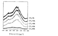
- FIG. 7 shows the dependence of Raman speckle on CF 4 flow rate.
- the Figure 7 the D band near 1350 cm -1, 1550 cm G band near -1 CF 4 60% to (CH 4 40%) is confirmed, it was found that the DLC is deposited. However, since no peak could be confirmed at 80% CF 4 (20% CH 4 ), it was found that the film was not a DLC film.
- FIG. 8 shows the result of X-ray photoelectron spectroscopy (XPS) of the CC bond peak of C1s
- FIG. 9 shows the result of X-ray photospectrometry of the CF bond peak of F1s. From FIG. 7, it was found that the CC bond decreased as the proportion of CF 4 increased. Further, FIG. 9 shows that the C—F bond increases as the proportion of CF 4 increases.
- XPS X-ray photoelectron spectroscopy
- CF 4 As described above, when CF 4 is 60% or less, it is confirmed that it is diamond-like carbon, and when CF 4 is 80% or more, it is no longer strictly diamond-like carbon. Was confirmed. However, in the following, for convenience, the material obtained when CF 4 is 0% is DLC, and the material obtained when CF 4 is included (including the case where CF 4 is 80% or more) is referred to as F-DLC. Call it.
- Titanium dioxide (TiO 2 ) is a typical example of titanium oxide (TiO x ) which is a surface coating material for an artificial object according to the present invention.
- a method for manufacturing a film using TiO 2 which is a typical example of titanium oxide will be described.
- a stainless steel SUS316 substrate having a size of 20 mm ⁇ 8 mm ⁇ 0.03 mm was subjected to ultrasonic cleaning with acetone for 10 minutes to form a film for coating with TiO 2 .
- a high frequency magnetron sputtering apparatus was used for film formation, and the sputtering gas was argon (Ar). The conditions are shown in Table 2.
- a living tissue-artificial material bonding apparatus according to an embodiment of the present invention.
- the living tissue and the artificial object are bonded by combining a single energy or any of low energy vibration, heat and pressure into a composite energy.
- the ratio of the raw material gases CH 4 and CF 4 is changed by the high-frequency plasma CVD method.
- the fluorine content can be controlled by a simple method.
- the contact angle in surface wettability increases and the surface energy decreases.
- the adhesive strength is high when the fluorine content is high in the raw material gas used.
- FIG. 1 shows a configuration of an apparatus A for bonding a living tissue and an artificial object according to an embodiment of the present invention.
- the bonding apparatus A has a mounting body 1 having an L-shaped cross section and a protruding base 1a at the bottom.
- a load cell 2 (load converter) is placed on the upper portion of the projecting portion 1 a of the placing body 1, and a vibrator (piezo actuator) 3 is placed on the upper portion of the load cell 2.
- a ceramic heater 4 is disposed above the vibrator 3 above the mounting body 1.
- FIG. 2 is a cross-sectional view of an enlarged configuration of this situation.
- the surface of the stent 7 is modified by applying the first coating film 7a to the surface of the stent 7 which is an artificial object.
- the blood vessel 6 that is a biological tissue and the stent 7 that is an artifact are placed on the upper part of the sample contact portion 5 in a state of being overlapped and brought into contact with each other, and the blood vessel 6 and the stent 7 are overlapped and brought into contact with each other.
- the vibrator 3 and the ceramic heater 4 serve as a support means for stacking and supporting the blood vessel 6 and the stent 7 between them.
- the tip of the ceramic heater 4 is in contact with the top of the stent 7.
- the stent 7 and the blood vessel 6 receive heat and pressure from the ceramic heater 4.
- the vibrator 3 gives a predetermined vibration to the sample contact portion 5, the blood vessel 6 and the stent 7.
- the stent 7, the blood vessel 6, and the sample contact portion 5 are sandwiched between the vibrator 3 and the ceramic heater 4, and in this case, low-energy vibration, heat, and pressure are simultaneously applied. That is, the vibrator 3 (or the sample contact portion 5) and the ceramic heater 4 serve as an applying unit that applies pressure to the laminated structure of the blood vessel 6 and the stent 7.
- the vibrator 3 serves as an applying unit that applies vibration to the laminated structure
- the ceramic heater 4 serves as an applying unit that applies heat to the laminated structure.
- protein denaturation is caused by combining low-energy vibration, heat, and pressure, which do not cause protein denaturation alone, to produce protein denaturation, and blood vessels 6 and artifacts that are living tissues.
- the stent 7 can be adhered.
- the ceramic heater 4 is connected to a ceramic heater controller 8 that controls the temperature of the ceramic heater 4.
- the ceramic heater controller 8 keeps the ceramic heater 4 at a set temperature.
- the vibrator 3 is connected to a piezo actuator driver 9 that controls the vibration of the vibrator 3.
- the piezo actuator driver 8 determines the vibration frequency and vibration amplitude of the vibrator 3.
- a capacitive displacement meter (capacitance gap detector) 10 is disposed on the side surface of the ceramic heater 4. This capacitive displacement meter 10 detects a gap between the vibrator 3 and the ceramic heater 4.
- the bonding apparatus A includes an oscilloscope 11 that measures the voltage of the ceramic heater 4 and the like.
- the bonding apparatus A has a thermography 12, and the thermography 12 measures and images the temperature of the surface of the stent 7 and the blood vessel 6, whereby the operator can determine the temperature of the surface of the stent 7 and the blood vessel 6. The condition can be diagnosed.
- the vibration amplitude, temperature, and pressure are measured using the oscilloscope 11, the thermography 12, and the load cell 2.
- the above-described bonding apparatus A includes an AD conversion apparatus 13, and the AD conversion apparatus 13 converts data of the load cell 2 into data such as voltage.
- the thermography 12 and the AD conversion device 13 are connected to a personal computer 14.
- the adhesive strength between the blood vessel (living tissue) 6 and the stent 7 (first coating film 7a) after bonding is high.
- This adhesive strength can be improved by using an appropriate material for the first coating film 7a.
- the pressure and temperature are not only applied to the interface between them, but also a part of the bonding apparatus A, for example, the interface between the ceramic heater 4 and the stent 7 in FIG. It is also applied to the interface with the part 5.
- the structure in which the blood vessel 6 and the stent 7 are bonded is separated from the bonding apparatus A particularly when the interface between the blood vessel 6 and the sample contact portion 5 is bonded to increase the bonding strength. Is difficult.
- the blood vessel 6 may be broken during this separation. Accordingly, it is necessary to make the adhesive strength at this interface as small as possible, or to prevent this interface from being adhered. Therefore, a PTFE plate (Polytetrafluorethylene plate: fluororesin processed plate) having low adhesion to the blood vessel (living tissue) 6 is used as the sample contact portion 5.
- a PTFE plate Polytetrafluorethylene plate: fluororesin processed plate
- a PTEE plate was laid on the vibrator, and the coated stainless steel and blood vessels were placed in this order.
- the coated stainless steel had a thickness of 0.03 mm and a strip shape of 8 mm ⁇ 20 mm.
- the blood vessel was a strip of 8 mm ⁇ 20 mm, and the coated stainless steel and the blood vessel were overlapped and contacted with each other by 5 mm.
- the size of the pressing surface of the ceramic heater was 4 mm ⁇ 1 mm. As described above, in this configuration, adhesion between the PTFE plate and the blood vessel does not occur.
- the bonding conditions are an adhesion temperature of 230 ° C., an adhesion pressure of 2.5 MPa, and an adhesion time of 120 sec.
- an adhesion temperature of 230 ° C., an adhesion pressure of 2.5 MPa, an adhesion time of 120 sec The vibration frequency was 12 kHz and the total vibration amplitude was 2 ⁇ m.
- Table 3 shows the results of an adhesion experiment between a blood vessel and stainless steel (no coating).
- the bonding pressure is particularly preferably 10 MPa or more, and the bonding temperature is particularly preferably 200 ° C. or more.
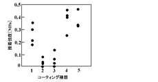
- FIG. 3 shows the adhesive strength between a stent and a blood vessel when various coating materials (including no coating material) are used and the surface of the stent is coated (including no coating material). Experimental data is shown.
- 1 is the adhesion strength between an uncoated stent and a blood vessel
- 2 is the adhesion between a stent coated with DLC not containing F using a source gas of CH 4 100% (CF 4 is not used) and the blood vessel.
- Strength 3 is the bond strength between the stent and blood vessel coated with F-DLC using 40% CF 4 (CH 4 60%) source gas
- 4 is the source gas 80% CF 4 (CH 4 20%) F-DLC-coated stent and blood vessel adhesion strength
- 5 indicates the TiO 2 -coated stent and blood vessel adhesion strength, respectively.
- the adhesion strength was measured only for DLC and F-DLC.
- the CF 4 concentration in forming the F-DLC was set to 0%, 20%, 40%, 60%, 70%, and 80%.
- Adhesion with the blood vessel was performed with a heater preheating temperature of 125 ° C. and a vibrator preheating temperature of 50 ° C., an adhesion temperature of 120 ° C., a pressure of 125 MPa, a vibration frequency of 11.84 kHz, a vibration amplitude of 5 ⁇ m, and an adhesion time of 120 seconds. The number of samples was 5 or more under each condition.
- the adhesive strength obtained in this case is shown in FIG.
- the bonding conditions are not the same as those in FIG. 3, the bonding strength is slightly different from that in FIG.
- CF 4 is 0 to 40%, the adhesive strength is lower than that without coating, and when CF 4 is 70% or more, the adhesive strength is improved as compared with the case without coating.
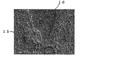
- FIG. 5 a tissue that appears to be a blood vessel remains on the surface of the stainless steel to which the F-DLC coating is applied, and the surface of the boundary between the surface where the tissue does not remain and the surface where the tissue remains is observed by SEM.
- the acceleration voltage was 1 kV at a magnification of 1000 times.
- the vascular tissue 15 and the stainless steel 16 are shown in the image photograph of FIG. In this case, it was found that the vascular tissue 15 was a mesh. Further, it was confirmed that there was a fiber having a thickness of about 1 ⁇ m.
- the sample contact portion 5 is replaced with the above-mentioned PTFE plate by using DLC not containing F or F-DLC using a raw material gas of CF 4 40% (CH 4 60%) or less, the sample contact portion 5 and blood vessel (living tissue) 6 are prevented from adhering.
- stainless steel is connected to the surface of the vibrator 3, and this surface may be coated with these materials.
- a stent 7 to which the blood vessel 6 should be originally bonded is coated by coating these materials on the portion where the blood vessel 6 may come into contact when performing the bonding operation. It can suppress that the blood vessel 6 adhere
- F-DLC with low DLC or F content (CF 4 is 40% or less) and F-DLC with high F content (CF 4 is 70% or more) are the same material system.
- both have the opposite characteristic with respect to the adhesiveness between living tissues.
- the former is coated on the bonding apparatus A side and the latter is coated on the stent 7 side, so that the living tissue and the stent 7 are particularly firmly and firmly secured using the bonding apparatus A. It becomes possible to adhere.
- a part of the aorta of a living pig was cut, and a stent cut into a strip shape of 8 mm ⁇ 20 mm was adhered to a blood vessel.
- the bonding conditions were a bonding time of 50 sec and a vibration frequency of 12 kHz.
- a stainless steel stent coated with an F-DLC film containing fluorine (F) using a raw material gas of CF 4 80% (CH 4 20%) was used.
- the bonding procedure includes (1) cutting and cooling the porcine aortic blood vessel in half, (2) inserting the stent into the blood vessel, (3) bonding the blood vessel and the stent, and (4) the bonded blood vessel. And cooling the stent to suppress tissue damage.
- the first coating film 7 a is formed on the stent 7 in advance by another device (means) not attached to the bonding apparatus A.
- the coated stent 7 is attached to the supporting means in the bonding apparatus A.
- a coating means for forming these coating films can also be provided in the bonding apparatus.
- a mechanism similar to that of the high-frequency plasma CVD apparatus or the like (in the case of DLC or F-DLC) or the high-frequency magnetron sputtering apparatus or the like (in the case of TiO 2 ) is provided at a location away from the vibrator 3 or the ceramic heater 4.
- the blood vessel 5 and the coated stent 7 may be bonded in the configuration shown in FIG.
- the applying means for applying pressure the applying means for applying vibration, and the applying means for applying heat
- those having various configurations other than the above-described configurations can be applied. It is clear that the same effect can be obtained by this.
- the stent 7 and the blood vessel (living tissue) 6 can be bonded together by applying at least one of pressure, vibration, and heat.
- FIG. 6 the stainless steel stent 22 and the blood vessel 21 that are the artificial tissue, which are the two types of coating materials constituting the sample S2 are applied to both the upper and lower surfaces, and the stent 22 and the blood vessel 21 that are the sample S2 are sandwiched vertically.
- a blood vessel 21 that is a living tissue is adhered to a stent 22 that is an artificial object by applying pressure to the canister 23 from both sides.
- the stent 22 has a second coating film 22a made of DLC (for example, (2) in FIG. 3) or F-DLC having a low F concentration (for example, (3) in FIG. 3) on the upper surface (on the side of the cannula 23), A first coating film 22b made of F-DLC having a high F concentration (for example, (4) in FIG. 3) is formed on the surface (blood vessel 21 side).
- TiO 2 (5) in FIG. 3 may be used as the first coating film 22b.
- the adhesive strength can be lowered, and the adhesive strength between the stent 22 and the blood vessel 21 (lower side) can be increased. That is, since the adhesive strength of the blood vessel 21 on the side of the stent 22 and the cannula 23 is low, they are difficult to adhere to each other. On the other hand, since the adhesive strength between the stent 22 and the blood vessel 21 is high, both are firmly adhered.
- the stent 22 coated with this configuration can be used to firmly bond both. Even when the above-described bonding apparatus A is used, if it is not desired to attach a living tissue to a surface other than one surface of the stent (the surface on which the first coating film 22b is formed), the stent 22 is coated as described above. It is effective to apply.
- one surface of the stent which is an artificial object, is coated with one type of material.
- the former region has an F-DLC (CF 4 having a high F concentration).
- a first coating film 22b made of 70% or more of F-DLC) is formed, and in the latter region, F-DLC or DLC (CF 4 having a CF 4 content of 40% or less) having a low F concentration is formed in the same manner as the upper surface.
- the artificial stent is made of stainless steel.
- a NiTi alloy can be used as another material of the stent.
- the blood vessel and stent can be adhered by the blood vessel and stent adhesion experiment, and stronger than the adhesion strength between the blood vessels can be realized.
- it was possible to improve the adhesive strength between the stent and the blood vessel by coating the stainless steel with an F-DLC film having a different fluorine content.
- a Bonding device S1 and S2 for living tissue and artifacts Sample 1 Mounting body 1a Protrusion base 2 Load cell (load transducer) 3. Vibrator (piezo actuator) 4 Ceramic heater 5 Sample contact part 6, 21 Blood vessel (biological tissue) 7, 22 Stents 7a, 22b ... First coating film 8 Ceramic heater controller 9 Piezo actuator (vibrator) driver 10 Capacitance displacement meter (capacitance gap detector) DESCRIPTION OF SYMBOLS 11 Oscilloscope 12 Thermography 13 AD converter 14 Personal computer 15 Vascular tissue 16 Stainless steel 22a Second coating film 23 Kanji
Landscapes
- Health & Medical Sciences (AREA)
- Epidemiology (AREA)
- Inorganic Chemistry (AREA)
- Heart & Thoracic Surgery (AREA)
- Surgery (AREA)
- Vascular Medicine (AREA)
- Chemical & Material Sciences (AREA)
- Life Sciences & Earth Sciences (AREA)
- Animal Behavior & Ethology (AREA)
- General Health & Medical Sciences (AREA)
- Public Health (AREA)
- Veterinary Medicine (AREA)
- Materials For Medical Uses (AREA)
- Prostheses (AREA)
Abstract
人工物を所望の形態で生体組織と良好に接着させる。 接着装置Aには振動子(ピエゾアクチュエータ)3が配置されている。この振動子3の上方に、セラミックヒータ4が配置されている。振動子3とセラミックヒータ4の間には、試料接触部5を介して、生体組織である血管6及び人工物であるステンレス製ステント7の積層構造とされた試料S1が載置される。試料接触部5として、Fを含有しないDLCあるいはCF440%(CH460%)以下の原料ガスを用いたF-DLCを用いれば、試料接触部5と血管(生体組織)6とが接着することが抑制される。
Description
本発明は、生体組織と人工物(ステント)とを接着させる接着装置の構成に関する。また、生体組織と接着されて用いられる人工物(ステント)の構成に関する。
血管等の生体組織に接着させることができる医療機器として、特許文献1に示されるステント、ステントグラフト等が広く知られている。
この特許文献1に示されているステント、ステントグラフト等は、その表面に生体組織接着性材料からなる部分を有する。この生体組織接着性材料としては、例えば湿潤コラーゲン、ポリウレタン、ビニロン、ゼラチン又はこれらの複合材料が示されている。この生体組織接着性材料に、生体組織を接触させた状態において、9x10²~1x10⁵N/m2の圧力、60~140℃の温度、及び1~100kHzの振動を付加している。
また、特許文献2に示されるように、スパッタリングにより基材に酸化チタンを表面コーティングした細胞接着性基材が知られている。ここでは、表面に酸化チタンをコーティングした基材を用いて細胞を培養させ、基材の細胞接着の状態を顕微鏡で観察している。表面に酸化チタンをコーティングした基材に培養した神経細胞は、神経細胞突起の伸長及グリア細胞の増殖に優れていることが示されている。
また、特許文献3に示されるように、フッ素化ダイヤモンドライクカーボン薄膜を用いたコーティングが知られている。フッ素化炭化水素化合物を含むガスを用いて製造されたダイヤモンドライクカーボン(ダイヤモンド状炭素)薄膜は、切削工具、金型、電子材料、光情報記録媒体、偏光板保護フィルム等の表面保護膜として有用である。
また、特許文献4に示されるように、ハイブリッド複合体を用いた医療用材料も知られている。ここでは、リン酸カルシウムまたは酸化チタンと基材とが化学結合してなる複合体の少なくとも一部が、さらに、軟組織に対して親和性を有する軟組織親和性向上物質で被覆されたハイブリッド複合体が示されている。
しかしながら、従来の接着装置では、従来のステント等(人工物)を生体組織に、所要の接着強度をもって良好に接着することが困難であった。
これは、従来の接着装置では、接着の際に、人工物であるステント等が生体組織に対してずれること、使用したかん子が生体組織に癒着してしまい生体組織から容易に取れなくなること、あるいは、本来はステントを接着させたくない箇所にステントが接着すること、等が原因である。特許文献1~4に記載の技術においても、こうした問題点が発生するために、ステントを所望の形態で生体組織と接着することは困難であった。
本発明は、かかる問題点に鑑みてなされたものであり、上記問題点を解決する発明を提供することを目的とする。
本発明は、上記課題を解決すべく、以下に掲げる構成とした。
本発明の生体組織と人工物の接着装置は、金属製の人工物と生体組織とを積層して支持する支持手段と、積層された金属製の人工物と生体組織に振動、熱及び圧力の少なくとも一つを付与する付与手段とを具備する、生体組織と人工物の接着装置であって、前記支持手段における前記生体組織と接する箇所に、フッ素を含有しないダイヤモンド状炭素(Diamond-Like Carbon:DLC)、又はCF4の組成比率を40%以下としたCH4とCF4の混合ガスを用いて高周波プラズマCVD法によって形成されたフッ素ドープダイヤモンド状炭素(F-DLC)からなるコーティング膜が形成されていることを特徴とする。
本発明の生体組織と人工物の接着装置において、前記コーティング膜がステンレス鋼の上に形成されている構成を具備することを特徴とする。
本発明の生体組織と人工物の接着装置は、前記付与手段によって、前記積層された金属製の人工物と生体組織における接着圧力が10MPa以上、又は接着温度が200℃以上とされることを特徴とする。
本発明のステントは、生体組織と接着されて用いられる金属製のステントであって、CF4の組成比率を70%以上としたCH4とCF4の混合ガスを用いた高周波プラズマCVD法によって形成されたフッ素ドープダイヤモンド状炭素(F-DLC)が、前記生体組織と接着される面にコーティングされていることを特徴とする。
本発明のステントは、前記生体組織と接着される面と異なる面に、フッ素を含有しないダイヤモンド状炭素(Diamond-Like Carbon:DLC)、又はCF4の組成比率を40%以下としたCH4とCF4の混合ガスを用いた高周波プラズマCVD法によって形成されたフッ素ドープダイヤモンド状炭素(F-DLC)がコーティングされていることを特徴とする。
本発明のステントは、ステンレス鋼又はNiTi合金からなることを特徴とする。
本発明の生体組織と人工物の接着装置は、金属製の人工物と生体組織とを積層して支持する支持手段と、積層された金属製の人工物と生体組織に振動、熱及び圧力の少なくとも一つを付与する付与手段とを具備する、生体組織と人工物の接着装置であって、前記支持手段における前記生体組織と接する箇所に、フッ素を含有しないダイヤモンド状炭素(Diamond-Like Carbon:DLC)、又はCF4の組成比率を40%以下としたCH4とCF4の混合ガスを用いて高周波プラズマCVD法によって形成されたフッ素ドープダイヤモンド状炭素(F-DLC)からなるコーティング膜が形成されていることを特徴とする。
本発明の生体組織と人工物の接着装置において、前記コーティング膜がステンレス鋼の上に形成されている構成を具備することを特徴とする。
本発明の生体組織と人工物の接着装置は、前記付与手段によって、前記積層された金属製の人工物と生体組織における接着圧力が10MPa以上、又は接着温度が200℃以上とされることを特徴とする。
本発明のステントは、生体組織と接着されて用いられる金属製のステントであって、CF4の組成比率を70%以上としたCH4とCF4の混合ガスを用いた高周波プラズマCVD法によって形成されたフッ素ドープダイヤモンド状炭素(F-DLC)が、前記生体組織と接着される面にコーティングされていることを特徴とする。
本発明のステントは、前記生体組織と接着される面と異なる面に、フッ素を含有しないダイヤモンド状炭素(Diamond-Like Carbon:DLC)、又はCF4の組成比率を40%以下としたCH4とCF4の混合ガスを用いた高周波プラズマCVD法によって形成されたフッ素ドープダイヤモンド状炭素(F-DLC)がコーティングされていることを特徴とする。
本発明のステントは、ステンレス鋼又はNiTi合金からなることを特徴とする。
本発明によれば、人工物を所望の形態で生体組織と良好に接着させることができる。
本発明の生体組織と人工物の接着装置、あるいはステントの実施の形態について説明する。これらにおいては、特にそのコーティング材料を使い分けている。初めに、このコーティング材料について説明する。このコーティング材料としては、非晶質炭素、及び酸化チタン(TiOx)からなるグループから少なくとも一つの材料が選択される。
このコーティング材料としては、まず非晶質炭素がある。ここで、非晶質炭素は、非晶質炭素と非晶質炭素に元素を添加した非晶質炭素を含む。非晶質炭素に添加する(ドープする)元素としては、Si、Ti、Cr、Al、Fe、Ni、Cu、Ag、Mo、W、F、H、N等がある。
ここで、非晶質炭素として、ダイヤモンド状炭素(Diamond-Like Carbon:DLC)膜について説明する。ダイヤモンド状炭素(DLC)膜は、炭素間の結合を骨格構造としたダイヤモンドに近いアモルファス炭素膜である。炭素原子から構成される物質は、その原子配列から結晶体固体、分子結晶体固体、非結晶体固体に分類できる。
結晶体固体は、その原子配列において長距離秩序を有する物質で、炭素からなる結晶体固体には結合状態によって数種類の同素体が存在する。分子結晶体固体は、炭素原子で構成される分子同士が分子間力で結合している物質である。非結晶体固体は、構成原子の長期的な配列規則性がなく、中距離秩序や短距離秩序が存在する物質と定義され、アモルファスと呼ばれる。非結晶体炭素膜は、アモルファス炭素と呼ばれる。
ダイヤモンド状炭素(DLC)は、アモルファス膜に含まれる。アモルファス膜の組成は主に炭素と水素からなる。膜中のsp3(結合角120度の立体的な結合)結合性結晶、sp2(結合角120度の平面的な結合)結合性結晶の結合比率と水素の含有量により、その物性が大きく変化する。
ダイヤモンド状炭素(DLC)膜は、高硬度、高耐摩耗性、低摩擦係数、絶縁性、高化学安定性、高腐食性、高ガスバリア性、高熱伝導率、高生体親和性、高赤外透過性等の特徴を有している。DLC膜は、電気・電子機器や切削工具、金型、自動車部品、光学部品、医療用機材(人工骨、眼内レンズなど)、PET(ポリエチレンテレフタレート)ボトルの酸素バリア膜など幅広く応用されている。
DLCの成膜法としては、アークイオンプレーティング法やスパッタリング法の物理蒸着法(PVD法)、高周波プラズマCVD法、イオン化蒸着法等がある。
成膜法によって、DLC膜の特性は異なる。例えば、高周波プラズマCVD法によって得られる膜質は、膜中の水素が多いため平滑性に優れ、摩擦係数も小さいが若干硬度が低い。イオン化蒸着法では、イオン化した炭化水素を直流で加速するため、膜中から水素がたたき出され膜が硬くなるが、若干面粗度が悪くなる。スパッタリング法は、水素フリーにすることが可能で膜を高硬度とすることができるが、これにより得られるDLC膜の粘性は低い。
また、同一の成膜方法を用いた場合でも、その成膜に用いる各種条件を変えることによって、得られるDLC膜の摩擦係数や硬度は変化する。摩擦係数や硬度は、膜中の水素含有量によって変化し、この水素含有量は、各種条件によって変化する。例えば、高周波プラズマCVD法によって成膜する場合、DLC膜の原料となる炭化水素系ガスの流量や圧力、電力などを変化させることにより、膜中の水素含有量を変化させることができる。
また、摺動環境において、DLC膜の低摩擦・高耐摩耗性を有効に機能させるためには、基板との密着力を確保する必要がある。摺動中に膜が消失してしまう要因として、DLC膜と基板との密着力が低いことが挙げられる。一般にシリコンや炭化タングステンを基板とした場合には比較的密着力が高いが、鉄や銅は密着力が低いために、その対応策が必要となる。
また、ダイヤモンド状炭素(DLC)膜の応力制御としてダイヤモンド状炭素(DLC)膜と基板との境界に中間層を形成し、それぞれの材料間の密着力を向上させ、ダイヤモンド状炭素(DLC)膜の高い内部応力を緩和することができる。
この中間層材料には、Si、W、Ti、Cr及びその炭化化合物が用いられる。また、DLC膜の内部応力を意図的に緩和する方法として、DLC膜への他元素の添加が有効である。この場合、DLC膜への内部応力を減少させてDLC膜の剥離を抑制する一方で、DLC膜の硬度や摩擦係数が変化することから、元素添加量が重要となる。フッ素(F)を添加したDLC膜(F-DLC)の場合、従来のDLCよりも膜の応力は下がり更に軟性化するため、基板への密着性、追従性が向上する。
この点を調べるため、DLCの薄膜を堆積させる基板としてSi基板を用いた場合について調べた。Si基板を用いた理由は、レーザーラマン分光光度計によるラマンスペクトルに基板の影響が少ないためである。Si基板は、アセトンに浸し10分間の超音波洗浄を行なった。DLCの成膜には高周波プラズマCVD装置を使用し、原料ガスはDLCの成膜材料となるCH4、Fを添加するための材料としてCF4を用いた。また、Fの添加量を変えるために、CF4の割合を全流量(CH4+CF4)に対して0%、20%、40%、60%、80%とCF4の割合が異なる5種類の試料を作成した。
DLC膜の膜厚は0.2μmとし、コーティングした材料をレーザーラマン分光光度計で測定し、C原子とF原子の結合の状態を調べ、DLCあるいはF-DLCの成膜を確認した。測定条件は、レーザ光波長:514.54nm、波数分解能:0.82cm-1、露光時間:60secとした。
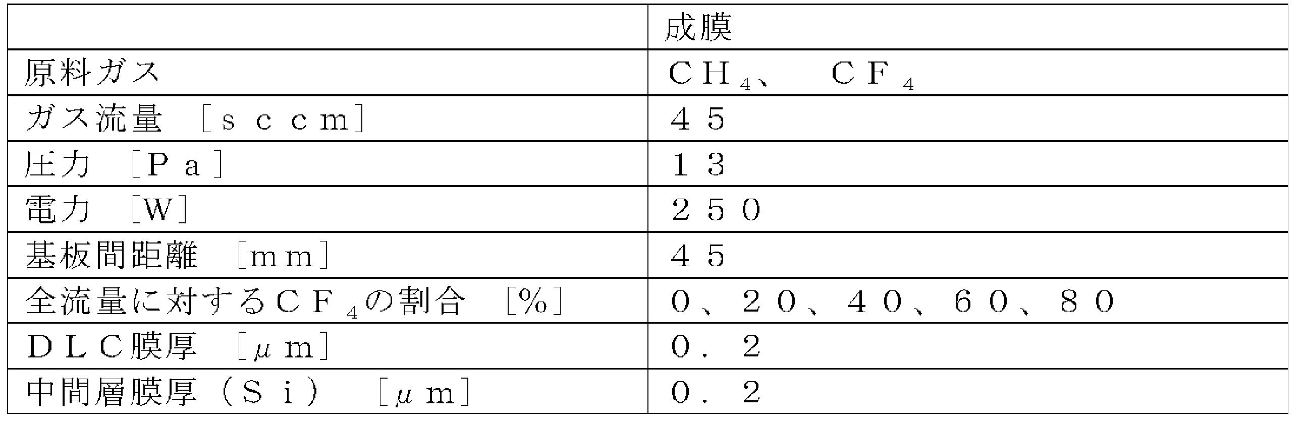
試料の作製にあたって、基板には大きさ20mm×8mm×0.03mmのステンレスSUS316を用い、CF4の割合を全流量(CH4+CF4)に対して0%、20%、40%、60%、80%でコーティングを行なった。また、ダイヤモンド状炭素(DLC)の付着強度を向上させるため、中間層としてシリコン(Si)をスパッタリングによりコーティングした。分析はX線光電子分光分析(Xray Photoelectron Spectroscopy:XPS)測定を行なった。
上述のコーティング条件を表1に示す。
ラマンスペクルのCF4流量依存性を図7に示す。図7により、1350cm-1付近のDバンドと、1550cm-1付近のGバンドがCF460%(CH440%)までは確認でき、DLCが成膜されていることがわかった。しかし、CF480%(CH420%)ではピークが確認できなかったため、DLC膜となっていないことがわかった。
C1sのC-C結合ピークのX線光電子分光分析(XPS)結果を図8に、F1sのC-F結合ピークのX線光分光分析結果を図9に示す。図7により、CF4の割合を増やしていくと、C-C結合が減少していることがわかった。また、図9により、CF4の割合を増やしていくとC-F結合が増加していることがわかった。
ラマン分光分析の結果から、CF460%(CH440%)までの試料がDLCであると確認されたが、CF480%(CH420%)ではDLCのピークが確認されなかった。
ここで、XPSのC1sピークの結果を見ると、CF4の割合を増やすとC-C結合が減少している。
F1sのピークを見ると、CF4の割合増加によってC-F結合の増加が確認された。C-F結合はCF2やCF3が主体となっていると考えられ、これらの結合が多く存在すると、DLC膜の表面の疎水性が高くなる。
なお、上記の通り、CF4が60%以下の場合にはダイヤモンド状炭素であることが確認され、CF4が80%以上である場合にはもはや厳密にはダイヤモンド状炭素とはなっていないことが確認された。しかしながら、以下では、便宜上、CF4が0%の場合に得られた材料をDLC、CF4が含まれる場合(CF4が80%以上の場合も含む)に得られた材料をF-DLCと呼称する。
次に、表面コーティング材料の他の例として、酸化チタン(TiOx)がある。本発明の人工物の表面コーティング材料である酸化チタン(TiOx)として、代表例なものとして二酸化チタン(TiO2)がある。
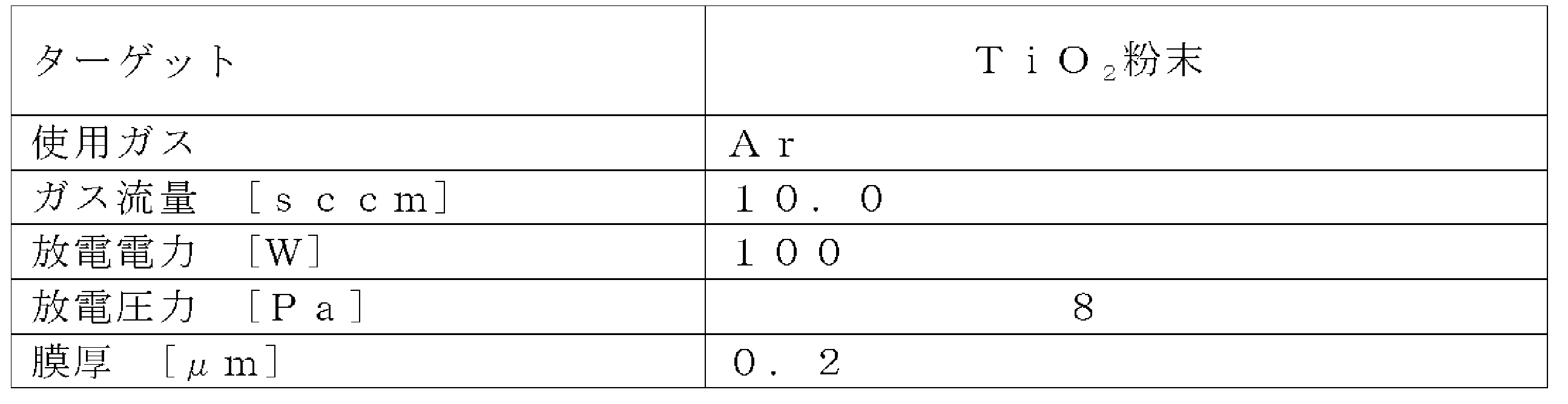
ここで、酸化チタンの代表例であるTiO2を用いた膜の作製方法について述べる。大きさ20mm×8mm×0.03mmのステンレスSUS316基板をアセトンにて10分間の超音波洗浄を行ない、TiO2のコーティングを施すための成膜を行なった。成膜には高周波マグネトロンスパッタ装置を使用し、スパッタリングガスはアルゴン(Ar)とした。条件を表2に示す。
本発明の実施の形態となる生体組織と人工物の接着装置について説明する。この生体組織と人工物の接着装置では、低エネルギの振動、熱及び圧力のいずれか一つの単エネルギ又は振動、熱及び圧力を合わせて複合エネルギにすることにより生体組織と人工物を接着する。
特許文献3に示されるようなフッ素化ダイヤモンドライクカーボン薄膜の物理蒸着法に比較して、本発明の上記実施例では高周波プラズマCVD法により原料ガスのCH4とCF4との割合比率を変えるという簡便な方法でフッ素含有量を制御することができる。
フッ素含有量の上昇に伴い、表面濡れ性における接触角は上昇し、表面エネルギは減少する。単純に考えれば、フッ素含有量が上昇すれば表面エネルギは減少し、基材との接触角が減少すると推察できる。しかしながら、上記の例によれば、使用する原料ガス中ではフッ素含有量が高い場合に接着力が高いことが判明した。
これらのコーティング材料を用いた接着装置について説明する。図1は、本発明の実施の形態となる生体組織と人工物との接着装置Aの構成を示す。図1において、接着装置Aは、L字状の断面で下部に突出台1aを有する載置体1を有する。この載置体1の突出部1aの上部にロードセル2(荷重変換器)が載置され、このロードセル2の上部に振動子(ピエゾアクチュエータ)3が配置されている。一方、載置体1の上部で、この振動子3の上方に、セラミックヒータ4が配置されている。
振動子3とセラミックヒータ4の間には、試料接触部5を介して、生体組織である血管6及び人工物であるステンレス製ステント7の積層構造とされた試料S1が載置される。図2は、この状況を拡大した構成の断面図である。
図2に示すように、人工物であるステント7の表面には第1のコーティング膜7aが施されていることにより、ステント7の表面が改質されている。このように、生体組織である血管6及び人工物であるステント7は、重ね合わせられ接触させられた状態で試料接触部5の上部に配置され、血管6及びステント7は重ね合わされ接触させらた状態で、振動子3とセラミックヒータ4の間に配置され挟持されている。すなわち、振動子3とセラミックヒータ4は、これらの間において血管6とステント7とを積層して支持する支持手段となる。
セラミックヒータ4の先端は、ステント7の上部に接触している。ステント7と血管6は、セラミックヒータ4からの熱と圧力を受ける。振動子3は、試料接触部5、血管6及びステント7に所定の振動を与える。ステント7、血管6、試料接触部5は、振動子3とセラミックヒータ4で挟まれており、この場合は低エネルギーの振動、熱及び圧力を同時に加えられている。すなわち、振動子3(あるいは試料接触部5)とセラミックヒータ4は、血管6とステント7の積層構造に圧力を印加する付与手段となる。また、振動子3は、この積層構造に振動を印加する付与手段となり、セラミックヒータ4は、この積層構造に熱を加える付与手段となる。
このように上記の接着装置Aでは、単独ではたんぱく質変性を生じさせない低エネルギの振動と熱及び圧力を合わせて複合エネルギにすることにより、たんぱく質変性を生じさせ、生体組織である血管6と人工物であるステント7を接着させることができる。
セラミックヒータ4は、セラミックヒータ4の温度を制御するセラミックヒータコントローラ8に接続されている。セラミックヒータコントローラ8は、セラミックヒータ4を設定温度に保つ。また、振動子3は、振動子3の振動を制御するピエゾアクチュエータドライバ9に接続されている。ピエゾアクチュエータドライバ8は、振動子3の振動周波数と振動振幅の大きさを決定する。
また、セラミックヒータ4の側面には、静電容量型変位計(静電容量型ギャップ検出器)10が配置されている。この静電容量型変位計10は、振動子3とセラミックヒータ4間のギャップを検出する。
さらに、上記の接着装置Aは、オシロスコープ11を備え、このオシロスコープ11は、セラミックヒータ4の電圧等を測定する。また、上記接着装置Aは、サーモグラフィ12を有し、このサーモグラフィ12は、ステント7、血管6の表面の温度を測定・画像化し、これによって、操作者は、ステント7、血管6の表面の温度状態を診断することができる。このように、振動振幅・温度・圧力は、オシロスコープ11、サーモグラフィ12及びロードセル2を用いて計測される。
上記した接着装置Aは、AD変換装置13を備え、このAD変換装置13は、ロードセル2のデータを電圧等のデータに変換する。サーモグラフィ12とAD変換装置13は、パーソナルコンピュータ14に接続されている。
図2の構成においては、接着後における血管(生体組織)6とステント7(第1のコーティング膜7a)との間の接着強度が高いことが要求される。この接着強度は、第1のコーティング膜7aの材料として適切なものを用いることにより、向上させることができる。
一方で、上記の圧力・温度は、これらの間の界面に印加されるだけでなく、接着装置Aの一部、例えば図2におけるセラミックヒータ4とステント7との界面、あるいは血管6と試料接触部5との界面にも印加される。このうち、特に血管6と試料接触部5との界面が接着されてその接着強度が高くなった場合には、血管6とステント7とが接着された構造を、この接着装置Aから分離することが困難である。あるいは、この分離の際に、血管6が破損することがある。従って、この界面における接着強度を、前記と逆に、極力小さく、あるいはこの界面を接着させないようにすることが必要である。そのため、この試料接触部5としては、血管(生体組織)6との密着性の低いPTFE板(Polytetrafluoroethylen板:フッ素樹脂加工板)が使用される。
ここで、ステンレス鋼(ステント)にコーティングを施すことで、血管との接着強度を大きくすることが可能かどうか確認するため、コーティングを施したステンレス鋼と血管との接着実験を行った。コーティング材料として、(1)DLC(Fドープなし)、(2)CF440%(CH460%)の原料ガスを用いたF-DLC、(3)CF460%(CH440%)の原料ガスを用いたF-DLC、(4)CF480%(CH420%)の原料ガスを用いたF-DLC、(5)TiO2の5種類を用いた。
振動子の上にPTEE板を敷き、その上にコーティングを施したステンレス鋼、血管の順番で載せた。コーティングを施したステンレス鋼は、厚み0.03mmとし8mm×20mmの短冊型とした。血管は、8mm×20mmの短冊型とし、コーティングを施したステンレス鋼と血管を5mm重ねて接触させて接着した。セラミックヒータの押付面の大きさは、4mm×1mmとした。前記の通り、この構成においては、PTFE板と血管との接着は生じていない。
接着条件は、振動無付加の場合には、接着温度230℃、接着圧力2.5MPa、接着時間120secとし、振動付加の場合には、接着温度230℃、接着圧力2.5MPa、接着時間120sec、振動周波数12kHz、振動全振幅2μmとした。
F-DLC(図3における(4))膜のコーティングを施したステンレス製ステントと血管を接着した試験片の引張試験を行なった後、F-DLCコーティングを施したステンレス鋼表面の組織観察を行なった。F-DLC膜のコーティングを施したステンレス鋼表面には、血管と見られる組織が残っており、組織が残っていない面と残っている面の境界の表面を走査型電子顕微鏡(Scanning Electron Microscope:SEM)で観察した。
まず、血管とステンレス鋼(無コーティング)の接着実験の結果を表3に示す。

血管の上にステンレス鋼(無コーティング)を載せ、接着圧力10MPa、接着時間120sec、接着温度130℃とした場合は、接着しなかった。接着圧力10MPa、接着時間120sec、接着温度200℃の場合は、接着した。このように、上記の接着装置Aを用いることにより、接着時間を120secと従来に比較して大幅に短縮できた。また、試験片の順番を入れ替え、ステンレス鋼(SUS)の上に血管を載せた場合も接着し、血管の上にステンレス鋼(SUS)を載せた場合よりも接着強度が大きかった。従って、この接着装置Aにおいては、接着圧力としては10MPa以上、接着温度としては200℃以上が特に好ましい。
次に、コーティング材料による血管のステントへの接着強度の変化を調べた。図3は、各種のコーティング材料(コーティング材料無しも含む)を用い、ステントの表面にコーティング(コーティング無しも含む)した場合のステントと血管の接着強度を示したもので、各材料につき4回分の実験データを示す。
図3において、1は、無コーティングのステントと血管の接着強度、2はCH4100%(CF4を使用せず)の原料ガスを用いたFを含有しないDLCをコーティングしたステントと血管の接着強度、3はCF440%(CH460%)の原料ガスを用いたF-DLCをコーティングしたステントと血管の接着強度、4はCF480%(CH420%)の原料ガスを用いたF-DLCをコーティングしたステントと血管の接着強度、5はTiO2をコーティングしたステントと血管の接着強度をそれぞれ示す。
Fを含有しないDLC(2)あるいはCF440%(CH460%)以下の原料ガスを用いたF-DLC(3)をコーティングした場合は、コーティングを施していないステント(1)よりも接着強度が小さくなり、CF480%(CH420%)以上の原料ガスを用いたF-DLC(4)をコーティングした場合には、コーティングを施していないステント(1)よりも接着強度が大きい傾向が見られた。また、TiO2(5)コーティングの場合の場合の接着強度も、(4)と同様に大きくなった。
更に、DLC、F-DLCに限定してこの接着強度の測定を行った。ここでは、F-DLCを成膜する際のCF4濃度を0%、20%、40%、60%、70%、80%とした。血管との接着は、ヒーター予熱温度125℃、振動子予熱温度50℃とし、接着温度120℃、圧力125MPa、振動周波数11.84kHz、振動振幅5μm、接着時間120secで行った。サンプルの数は、各条件で5回以上とした。この場合に得られた接着強度を図4に示す。なお、ここで、接着条件が図3の場合とは等しくないために、接着強度が図3の場合とはわずかに異なる。CF4が0~40%の場合には、無コーティングの場合と比べて接着強度は低下し、CF4が70%以上では無コーティングの場合と比べて接着強度は向上する。
CF480%(CH420%)以上の原料ガスを用いたF-DLCのコーティングを施したステンレス鋼と血管とを接着し、剥がした後、コーティングを施したステンレス鋼上に残った血管を観察した結果のSEM画像写真を図5に示す。図5において、F-DLCコーティングを施したステンレス鋼表面には、血管とみられる組織が残っており、組織が残っていない面と残っている面の組織の境界の表面をSEMで観察した。なお、倍率1000倍で、加速電圧は1kVであった。図5の画像写真に、血管組織15とステンレス鋼16が示されている。この場合、血管組織15が網目状となっている様子がわかった。また、約1μmの太さの繊維があることを確認した。
この結果より、特にこのコーティングを施したステントと血管との接着が可能であり、かつ血管同士の接着強度よりも強固であることから、例えば、ステントを血管に接着し、ステントのずれを防ぐことが可能である。
図3、4の結果より、CF470%以上(CH430%以下)の原料ガスを用いたF-DLC又はTiO2を第1のコーティング膜7aの材料として用いることで、非常に強固な接着を実現できることが明らかである。
一方で、試料接触部5として、前記のPTFE板の代わりに、Fを含有しないDLCあるいはCF440%(CH460%)以下の原料ガスを用いたF-DLCを用いれば、試料接触部5と血管(生体組織)6とが接着することが抑制される。この場合には、図2において、振動子3表面にステンレス鋼を接続し、この表面をこれらの材料でコーティングすればよい。更に、この部分だけでなく、接着装置Aの内部において、接着作業を行なう際に血管6が接触する可能性のある箇所にこれらの材料をコーティングすることによって、血管6を本来接着するべきステント7以外の箇所に血管6が接着されることを抑制することができる。
特に、DLC又はFの含有量が低い(CF4が40%以下の)F-DLCと、Fの含有量の高い(CF4が70%以上の)F-DLCは、同一の材料系であり、同一の成膜装置を用いて形成できるにも関わらず、両者は、生体組織との間の接着性に対しては、逆の特性をもつ。このため、同一の成膜装置を用い、前者を接着装置A側に、後者をステント7側にコーティングすることにより、生体組織とステント7とを、この接着装置Aを用いて特に確実に強固に接着することが可能となる。
本発明の一実施例として、生存中の豚の大動脈に一部切り込みを入れ、8mm×20mmの短冊型にカットしたステントを血管内に接着した。接着条件は、接着時間50sec、振動周波数12kHzとした。CF480%(CH420%)の原料ガスを用いたフッ素(F)を含有するF-DLC膜のコーティングを施したステンレス製ステントを使用した。接着手順は、(1)豚の大動脈の血管を半分に切断冷却する工程、(2)血管内にステントを挿入する工程、(3)血管とステントを接着する工程、及び(4)接着した血管とステントを冷却して組織損傷を抑える工程であった。その結果、上記の接着装置を用いて、血管に損傷を与えずに、ステントを血管に装着することができた。また、約1時間の拍動下において接着したステントと血管が剥がれないことを確認した。
上記の例では、接着装置Aに装着されていない他の装置(手段)で前もって第1のコーティング膜7aをステント7上に形成する。このコーティング済のステント7を接着装置Aにおける支持手段に装着している。しかしながら、これらのコーティング膜を形成するコーティング手段を接着装置内に設けることもできる。この場合は、上記の振動子3やセラミックヒータ4等と離れた箇所において高周波プラズマCVD装置等(DLC、F-DLCの場合)あるいは高周波マグネトロンスパッタ装置等(TiO2の場合)と同様の機構を設ける。これにより、ステント7の表面に第1のコーティング膜7aを形成した後に、図2の構成で血管5とこのコーティング済みのステント7とを接着すればよい。
また、圧力を加える付与手段、振動を加える付与手段、熱を加える付与手段としては、上記の構成以外にも各種の構成のものが適用できる。これによっても、同様の効果を奏することは明らかである。この際、少なくとも圧力、振動、熱のいずれかが加えられることによってステント7と血管(生体組織)6とを接着することができる。
上記の例では、ステンレス製ステントにおける生体組織が接着される側のみに、その接着性を高めるコーティングを施した。しかしながら、このステントにおいても、上記の2種類のコーティングを使い分けて使用することができる。この例が図6に示された構成である。図6で、試料S2を構成する2種類のコーティング材料を上下両表面に施した人工物であるステンレス製ステント22と生体組織である血管21、試料S2であるステント22と血管21を上下に挟持するかん子23の構成図である。図6において、生体組織である血管21は、かん子23に両側から圧力を加えられることによって、人工物であるステント22に接着される。
ステント22は、上表面(かん子23側)に、DLC(例えば図3における(2))あるいはF濃度の低いF-DLC(例えば図3における(3))からなる第2のコーティング膜22a、下表面(血管21側)にF濃度の高いF-DLC(例えば図3における(4))からなる第1のコーティング膜22bが形成されている。前記と同様に、第1のコーティング膜22bとして、TiO2(図3における(5))を用いてもよい。
上述の例の場合、血管21が仮にステント22とかん子23(上側)側に入り込んでも、その接着強度は低くでき、ステント22と血管21(下側)の接着強度は高くできる。すなわち、ステント22とかん子23側における血管21の接着強度が低いために両者は接着し難く、一方ステント22と血管21の接着強度は高いために両者は強固に接着する。
上記の接着装置Aを用いずに、かん子23を用いて血管23とステント22とを接着する場合、この構成でコーティングされたステント22を用いることによって、両者を強固に接着することができる。また、上記の接着装置Aを用いる場合においても、生体組織をステントの一面(第1のコーティング膜22bが形成された面)以外に付着させたくない場合には、ステント22に上記の構成のコーティングを施すことは有効である。
また、上記の例では、人工物であるステントの1面において1種類の材料からなるコーティングを施していた。しかしながら、これを2種類以上とすることも可能である。例えば、図6中のステント22の下側の面において、血管21を接着させたい領域とこれを接着させたくない領域とがある場合、前者の領域にはF濃度の高いF-DLC(CF4が70%以上のF-DLC)からなる第1のコーティング膜22bを形成し、後者の領域には上側の面と同様にF濃度の低いF-DLCあるいはDLC(CF4が40%以下のF-DLC又はDLC)からなるコーティング膜を形成することも可能である。こうした場合には、特にDLCあるいはF-DLCをこれらのコーティング材料として用いることにより、原料ガスの成分(CF4/CH4)の調整を行うだけで、同一のコーティング装置を用いて、これらのコーティング膜の形成を行うことができる。
また、上記の例では、人工物であるステントとしてステンレス製のものについて述べたが、ステントのその他の材料として、例えばNiTi合金等も使用することができる。
上述したように、血管とステントの接着実験により、血管とステントの接着が可能であり、かつ血管同士の接着強度よりも強固な接着を実現できた。また、ステンレス鋼にフッ素含有率を変更したF-DLC膜のコーティングを施すことで、ステントと血管との接着強度の向上を実現できた。あるいは、フッ素含有率をこれと変えることによって、血管とステントとの接着をさせないことができることも確認された。血管が接着することが好ましくない箇所にこの組成のコーティング膜を形成することにより、この箇所への血管の付着を抑制することができた。
A 生体組織と人工物の接着装置
S1、S2 試料
1 載置体
1a 突出台
2 ロードセル(荷重変換器)
3 振動子(ピエゾアクチュエータ)
4 セラミックヒータ
5 試料接触部
6、21 血管(生体組織)
7、22 ステント
7a、22b … 第1のコーティング膜
8 セラミックヒータコントローラ
9 ピエゾアクチュエータ(振動子)ドライバ
10 静電容量型変位計(静電容量型ギャップ検出器)
11 オシロスコープ
12 サーモグラフィ
13 AD変換器
14 パーソナルコンピュータ
15 血管組織
16 ステンレス鋼
22a 第2のコーティング膜
23 かん子
S1、S2 試料
1 載置体
1a 突出台
2 ロードセル(荷重変換器)
3 振動子(ピエゾアクチュエータ)
4 セラミックヒータ
5 試料接触部
6、21 血管(生体組織)
7、22 ステント
7a、22b … 第1のコーティング膜
8 セラミックヒータコントローラ
9 ピエゾアクチュエータ(振動子)ドライバ
10 静電容量型変位計(静電容量型ギャップ検出器)
11 オシロスコープ
12 サーモグラフィ
13 AD変換器
14 パーソナルコンピュータ
15 血管組織
16 ステンレス鋼
22a 第2のコーティング膜
23 かん子
Claims (6)
- 金属製の人工物と生体組織とを積層して支持する支持手段と、積層された金属製の人工物と生体組織に振動、熱及び圧力の少なくとも一つを付与する付与手段とを具備する、生体組織と人工物の接着装置であって、
前記支持手段における前記生体組織と接する箇所に、
フッ素を含有しないダイヤモンド状炭素(Diamond-Like Carbon:DLC)、又はCF4の組成比率を40%以下としたCH4とCF4の混合ガスを用いて高周波プラズマCVD法によって形成されたフッ素ドープダイヤモンド状炭素(F-DLC)からなるコーティング膜が形成されていることを特徴とする、生体組織と人工物の接着装置。 - 前記コーティング膜がステンレス鋼の上に形成されている構成を具備することを特徴とする請求項1に記載の、生体組織と人工物の接着装置。
- 前記付与手段によって、
前記積層された金属製の人工物と生体組織における接着圧力が10MPa以上、又は接着温度が200℃以上とされることを特徴とする請求項1又は2に記載の、生体組織と人工物の接着装置。 - 生体組織と接着されて用いられる金属製のステントであって、
CF4の組成比率を70%以上としたCH4とCF4の混合ガスを用いた高周波プラズマCVD法によって形成されたフッ素ドープダイヤモンド状炭素(F-DLC)が、前記生体組織と接着される面にコーティングされていることを特徴とするステント。 - 前記生体組織と接着される面と異なる面に、
フッ素を含有しないダイヤモンド状炭素(Diamond-Like Carbon:DLC)、又はCF4の組成比率を40%以下としたCH4とCF4の混合ガスを用いた高周波プラズマCVD法によって形成されたフッ素ドープダイヤモンド状炭素(F-DLC)がコーティングされていることを特徴とする請求項4に記載のステント。 - ステンレス鋼又はNiTi合金からなることを特徴とする請求項4又は5に記載のステント。
Priority Applications (1)
| Application Number | Priority Date | Filing Date | Title |
|---|---|---|---|
| JP2011510193A JP5543435B2 (ja) | 2009-04-20 | 2010-04-20 | 生体組織と人工物の接着装置、ステント |
Applications Claiming Priority (2)
| Application Number | Priority Date | Filing Date | Title |
|---|---|---|---|
| JP2009102468 | 2009-04-20 | ||
| JP2009-102468 | 2009-04-20 |
Publications (1)
| Publication Number | Publication Date |
|---|---|
| WO2010122773A1 true WO2010122773A1 (ja) | 2010-10-28 |
Family
ID=43010900
Family Applications (1)
| Application Number | Title | Priority Date | Filing Date |
|---|---|---|---|
| PCT/JP2010/002828 Ceased WO2010122773A1 (ja) | 2009-04-20 | 2010-04-20 | 生体組織と人工物の接着装置、ステント |
Country Status (2)
| Country | Link |
|---|---|
| JP (1) | JP5543435B2 (ja) |
| WO (1) | WO2010122773A1 (ja) |
Cited By (1)
| Publication number | Priority date | Publication date | Assignee | Title |
|---|---|---|---|---|
| WO2018088459A1 (ja) * | 2016-11-11 | 2018-05-17 | 学校法人金沢医科大学 | 抗菌性部材 |
Citations (4)
| Publication number | Priority date | Publication date | Assignee | Title |
|---|---|---|---|---|
| JPH08337874A (ja) * | 1995-06-13 | 1996-12-24 | Matsushita Electric Ind Co Ltd | 基材表面被覆層及びその形成方法並びに熱交換器用フィン及びその製造方法。 |
| JP2001029447A (ja) * | 1999-07-19 | 2001-02-06 | Terumo Corp | 体内埋め込み医療器 |
| JP2001238962A (ja) * | 2000-02-29 | 2001-09-04 | Japan Lifeline Co Ltd | 医療用挿通線体 |
| JP2007229270A (ja) * | 2006-03-01 | 2007-09-13 | Tokyo Medical & Dental Univ | 生体組織接着装置 |
-
2010
- 2010-04-20 WO PCT/JP2010/002828 patent/WO2010122773A1/ja not_active Ceased
- 2010-04-20 JP JP2011510193A patent/JP5543435B2/ja active Active
Patent Citations (4)
| Publication number | Priority date | Publication date | Assignee | Title |
|---|---|---|---|---|
| JPH08337874A (ja) * | 1995-06-13 | 1996-12-24 | Matsushita Electric Ind Co Ltd | 基材表面被覆層及びその形成方法並びに熱交換器用フィン及びその製造方法。 |
| JP2001029447A (ja) * | 1999-07-19 | 2001-02-06 | Terumo Corp | 体内埋め込み医療器 |
| JP2001238962A (ja) * | 2000-02-29 | 2001-09-04 | Japan Lifeline Co Ltd | 医療用挿通線体 |
| JP2007229270A (ja) * | 2006-03-01 | 2007-09-13 | Tokyo Medical & Dental Univ | 生体組織接着装置 |
Cited By (4)
| Publication number | Priority date | Publication date | Assignee | Title |
|---|---|---|---|---|
| WO2018088459A1 (ja) * | 2016-11-11 | 2018-05-17 | 学校法人金沢医科大学 | 抗菌性部材 |
| JPWO2018088459A1 (ja) * | 2016-11-11 | 2019-10-10 | 学校法人金沢医科大学 | 抗菌性部材 |
| EP3539382A4 (en) * | 2016-11-11 | 2020-06-10 | Kanazawa Medical University | ANTIBACTERIAL ELEMENT |
| US10695467B2 (en) | 2016-11-11 | 2020-06-30 | Kanazawa Medical University | Antibacterial member |
Also Published As
| Publication number | Publication date |
|---|---|
| JPWO2010122773A1 (ja) | 2012-10-25 |
| JP5543435B2 (ja) | 2014-07-09 |
Similar Documents
| Publication | Publication Date | Title |
|---|---|---|
| Choy et al. | Functionally graded diamond-like carbon coatings on metallic substrates | |
| Yiu et al. | Thin film metallic glasses: Properties, applications and future | |
| Morshed et al. | Stress and adhesion in DLC coatings on 316L stainless steel deposited by a neutral beam source | |
| Kang et al. | Effects of TiCN interlayer on bonding characteristics and mechanical properties of DLC-coated Ti-6Al-4V ELI alloy | |
| Hovsepian et al. | Development of superlattice CrN/NbN coatings for joint replacements deposited by high power impulse magnetron sputtering | |
| Hee et al. | Corrosion behaviour and microstructure of tantalum film on Ti6Al4V substrate by filtered cathodic vacuum arc deposition | |
| Toyonaga et al. | The property of adhesion and biocompatibility of silicon and fluorine doped diamond-like carbon films | |
| Li et al. | Surface modification of 316L stainless steel by diamond-like carbon films: RW Li et al. | |
| JP4209815B2 (ja) | 医療用器具 | |
| Shim et al. | Effects of a titanium dioxide thin film for improving the biocompatibility of diamond-like coated coronary stents | |
| CN102844462B (zh) | 用于CoCrMo基材的涂层 | |
| Wei et al. | Understanding the tribo-corrosion behaviors and mechanism of Si/N-DLC films in marine environment | |
| JP5543435B2 (ja) | 生体組織と人工物の接着装置、ステント | |
| He et al. | Microstructure and tribological properties of DLC films with varying Ti interlayer thicknesses on HNBR substrate deposited by PVD | |
| Rong et al. | Improving the mechanical and tribological properties of amorphous carbon-based films by an aC/Zr/ZrN multilayered interlayer | |
| RU2428516C2 (ru) | Способ получения наноструктурированного градиентного оксидного покрытия из каталитического материала методом магнетронного напыления | |
| Schauer et al. | Plasma deposition of elastic wear resistant Si–C coatings on nickel-titanium for biomedical applications | |
| Wasy et al. | Thickness dependent properties of diamond-like carbon coatings by filtered cathodic vacuum arc deposition | |
| Major et al. | Wear mechanisms of the biotribological nanocomposite a‐C: H coatings implanted by metallic nanoparticles | |
| Lubna et al. | Analysis of titanium-coated glass and imidex (PI) laser bonded samples | |
| Kalita et al. | Structure and mechanical properties of a three-dimensional capillary porous titanium coating | |
| Kao et al. | Enhanced tribological, electrochemical, and biocompatibility properties of Ti6Al4V alloy through gas nitriding and CN coating deposition | |
| JP5636857B2 (ja) | 生体組織接着用柔軟性金属箔テープ及びその接着方法 | |
| KR102918627B1 (ko) | 의료 기기용 금속 재료, 의료 기기용 금속 재료의 제조 방법, 및 의료 기기 | |
| Lee et al. | Microtensile strain on the corrosion performance of diamond‐like carbon coating |
Legal Events
| Date | Code | Title | Description |
|---|---|---|---|
| 121 | Ep: the epo has been informed by wipo that ep was designated in this application |
Ref document number: 10766835 Country of ref document: EP Kind code of ref document: A1 |
|
| ENP | Entry into the national phase |
Ref document number: 2011510193 Country of ref document: JP Kind code of ref document: A |
|
| NENP | Non-entry into the national phase |
Ref country code: DE |
|
| 122 | Ep: pct application non-entry in european phase |
Ref document number: 10766835 Country of ref document: EP Kind code of ref document: A1 |