WO2010116659A1 - 記録媒体、再生装置、及び集積回路 - Google Patents
記録媒体、再生装置、及び集積回路 Download PDFInfo
- Publication number
- WO2010116659A1 WO2010116659A1 PCT/JP2010/002218 JP2010002218W WO2010116659A1 WO 2010116659 A1 WO2010116659 A1 WO 2010116659A1 JP 2010002218 W JP2010002218 W JP 2010002218W WO 2010116659 A1 WO2010116659 A1 WO 2010116659A1
- Authority
- WO
- WIPO (PCT)
- Prior art keywords
- stream
- data
- extent
- playback
- video
- Prior art date
Links
- 239000000872 buffer Substances 0.000 claims abstract description 280
- 238000012545 processing Methods 0.000 claims description 225
- 230000015654 memory Effects 0.000 claims description 170
- 239000004065 semiconductor Substances 0.000 claims description 37
- 238000003860 storage Methods 0.000 claims description 22
- 230000005236 sound signal Effects 0.000 claims description 5
- 239000000284 extract Substances 0.000 abstract description 27
- 238000000034 method Methods 0.000 description 282
- 238000010586 diagram Methods 0.000 description 183
- 230000008569 process Effects 0.000 description 177
- 238000012546 transfer Methods 0.000 description 120
- 102100029055 Exostosin-1 Human genes 0.000 description 91
- 102100029074 Exostosin-2 Human genes 0.000 description 91
- 101000918311 Homo sapiens Exostosin-1 Proteins 0.000 description 91
- 101000918275 Homo sapiens Exostosin-2 Proteins 0.000 description 91
- 230000001419 dependent effect Effects 0.000 description 83
- 230000003287 optical effect Effects 0.000 description 51
- 230000007704 transition Effects 0.000 description 35
- 230000007423 decrease Effects 0.000 description 33
- 238000009826 distribution Methods 0.000 description 33
- 101100226366 Arabidopsis thaliana EXT3 gene Proteins 0.000 description 32
- 210000003128 head Anatomy 0.000 description 32
- 208000034420 multiple type III exostoses Diseases 0.000 description 32
- 230000036316 preload Effects 0.000 description 29
- 230000008859 change Effects 0.000 description 25
- 230000006835 compression Effects 0.000 description 25
- 238000007906 compression Methods 0.000 description 25
- 238000006243 chemical reaction Methods 0.000 description 24
- 230000005540 biological transmission Effects 0.000 description 21
- 230000014509 gene expression Effects 0.000 description 19
- 230000003068 static effect Effects 0.000 description 19
- 238000005516 engineering process Methods 0.000 description 13
- 230000006870 function Effects 0.000 description 13
- 239000011521 glass Substances 0.000 description 13
- 238000000926 separation method Methods 0.000 description 13
- 102100036727 Deformed epidermal autoregulatory factor 1 homolog Human genes 0.000 description 12
- 230000015572 biosynthetic process Effects 0.000 description 11
- 230000033001 locomotion Effects 0.000 description 11
- 238000007726 management method Methods 0.000 description 11
- 239000000047 product Substances 0.000 description 11
- 238000003786 synthesis reaction Methods 0.000 description 11
- 239000004973 liquid crystal related substance Substances 0.000 description 10
- 238000012937 correction Methods 0.000 description 9
- 238000004519 manufacturing process Methods 0.000 description 9
- 230000004044 response Effects 0.000 description 8
- 239000013598 vector Substances 0.000 description 8
- 239000011159 matrix material Substances 0.000 description 7
- 102100028505 6-pyruvoyl tetrahydrobiopterin synthase Human genes 0.000 description 6
- 239000000463 material Substances 0.000 description 6
- 238000001094 photothermal spectroscopy Methods 0.000 description 6
- 230000008929 regeneration Effects 0.000 description 6
- 238000011069 regeneration method Methods 0.000 description 6
- 230000002123 temporal effect Effects 0.000 description 6
- 101100382854 Arabidopsis thaliana CCD7 gene Proteins 0.000 description 5
- 101100129496 Arabidopsis thaliana CYP711A1 gene Proteins 0.000 description 5
- 101100129499 Arabidopsis thaliana MAX2 gene Proteins 0.000 description 5
- 101100083446 Danio rerio plekhh1 gene Proteins 0.000 description 5
- 238000004364 calculation method Methods 0.000 description 5
- 238000001824 photoionisation detection Methods 0.000 description 5
- 238000009877 rendering Methods 0.000 description 5
- 238000006073 displacement reaction Methods 0.000 description 4
- 230000007246 mechanism Effects 0.000 description 4
- 238000002156 mixing Methods 0.000 description 4
- 239000013589 supplement Substances 0.000 description 4
- 230000001360 synchronised effect Effects 0.000 description 4
- 238000004132 cross linking Methods 0.000 description 3
- 238000013461 design Methods 0.000 description 3
- 238000001093 holography Methods 0.000 description 3
- 230000002452 interceptive effect Effects 0.000 description 3
- 230000009191 jumping Effects 0.000 description 3
- 230000036961 partial effect Effects 0.000 description 3
- 230000000153 supplemental effect Effects 0.000 description 3
- 238000004458 analytical method Methods 0.000 description 2
- 230000008901 benefit Effects 0.000 description 2
- 238000004891 communication Methods 0.000 description 2
- 239000002131 composite material Substances 0.000 description 2
- 239000000945 filler Substances 0.000 description 2
- 230000010287 polarization Effects 0.000 description 2
- 238000003825 pressing Methods 0.000 description 2
- 238000011946 reduction process Methods 0.000 description 2
- 230000002829 reductive effect Effects 0.000 description 2
- 230000001172 regenerating effect Effects 0.000 description 2
- 230000002441 reversible effect Effects 0.000 description 2
- 230000008054 signal transmission Effects 0.000 description 2
- 230000002459 sustained effect Effects 0.000 description 2
- 230000000007 visual effect Effects 0.000 description 2
- NAWXUBYGYWOOIX-SFHVURJKSA-N (2s)-2-[[4-[2-(2,4-diaminoquinazolin-6-yl)ethyl]benzoyl]amino]-4-methylidenepentanedioic acid Chemical compound C1=CC2=NC(N)=NC(N)=C2C=C1CCC1=CC=C(C(=O)N[C@@H](CC(=C)C(O)=O)C(O)=O)C=C1 NAWXUBYGYWOOIX-SFHVURJKSA-N 0.000 description 1
- GHOKWGTUZJEAQD-ZETCQYMHSA-N (D)-(+)-Pantothenic acid Chemical compound OCC(C)(C)[C@@H](O)C(=O)NCCC(O)=O GHOKWGTUZJEAQD-ZETCQYMHSA-N 0.000 description 1
- 206010047571 Visual impairment Diseases 0.000 description 1
- 238000009825 accumulation Methods 0.000 description 1
- 230000006978 adaptation Effects 0.000 description 1
- 230000001174 ascending effect Effects 0.000 description 1
- 239000000470 constituent Substances 0.000 description 1
- 238000013500 data storage Methods 0.000 description 1
- 230000003247 decreasing effect Effects 0.000 description 1
- 230000003111 delayed effect Effects 0.000 description 1
- 238000011161 development Methods 0.000 description 1
- 230000018109 developmental process Effects 0.000 description 1
- 230000000694 effects Effects 0.000 description 1
- 238000011156 evaluation Methods 0.000 description 1
- 210000000744 eyelid Anatomy 0.000 description 1
- 230000006872 improvement Effects 0.000 description 1
- 239000000203 mixture Substances 0.000 description 1
- 238000012986 modification Methods 0.000 description 1
- 230000004048 modification Effects 0.000 description 1
- 238000005457 optimization Methods 0.000 description 1
- 238000012856 packing Methods 0.000 description 1
- 230000002093 peripheral effect Effects 0.000 description 1
- 230000000750 progressive effect Effects 0.000 description 1
- 230000009467 reduction Effects 0.000 description 1
- 238000013468 resource allocation Methods 0.000 description 1
- 238000005070 sampling Methods 0.000 description 1
- 239000007787 solid Substances 0.000 description 1
- 239000000126 substance Substances 0.000 description 1
- 238000013519 translation Methods 0.000 description 1
Images


Classifications
-
- H—ELECTRICITY
- H04—ELECTRIC COMMUNICATION TECHNIQUE
- H04N—PICTORIAL COMMUNICATION, e.g. TELEVISION
- H04N5/00—Details of television systems
- H04N5/76—Television signal recording
- H04N5/84—Television signal recording using optical recording
- H04N5/85—Television signal recording using optical recording on discs or drums
-
- G—PHYSICS
- G11—INFORMATION STORAGE
- G11B—INFORMATION STORAGE BASED ON RELATIVE MOVEMENT BETWEEN RECORD CARRIER AND TRANSDUCER
- G11B20/00—Signal processing not specific to the method of recording or reproducing; Circuits therefor
- G11B20/10—Digital recording or reproducing
- G11B20/10527—Audio or video recording; Data buffering arrangements
-
- G—PHYSICS
- G11—INFORMATION STORAGE
- G11B—INFORMATION STORAGE BASED ON RELATIVE MOVEMENT BETWEEN RECORD CARRIER AND TRANSDUCER
- G11B20/00—Signal processing not specific to the method of recording or reproducing; Circuits therefor
- G11B20/10—Digital recording or reproducing
- G11B20/12—Formatting, e.g. arrangement of data block or words on the record carriers
- G11B20/1217—Formatting, e.g. arrangement of data block or words on the record carriers on discs
- G11B20/1251—Formatting, e.g. arrangement of data block or words on the record carriers on discs for continuous data, e.g. digitised analog information signals, pulse code modulated [PCM] data
-
- G—PHYSICS
- G11—INFORMATION STORAGE
- G11B—INFORMATION STORAGE BASED ON RELATIVE MOVEMENT BETWEEN RECORD CARRIER AND TRANSDUCER
- G11B27/00—Editing; Indexing; Addressing; Timing or synchronising; Monitoring; Measuring tape travel
- G11B27/02—Editing, e.g. varying the order of information signals recorded on, or reproduced from, record carriers
- G11B27/031—Electronic editing of digitised analogue information signals, e.g. audio or video signals
- G11B27/034—Electronic editing of digitised analogue information signals, e.g. audio or video signals on discs
-
- G—PHYSICS
- G11—INFORMATION STORAGE
- G11B—INFORMATION STORAGE BASED ON RELATIVE MOVEMENT BETWEEN RECORD CARRIER AND TRANSDUCER
- G11B27/00—Editing; Indexing; Addressing; Timing or synchronising; Monitoring; Measuring tape travel
- G11B27/10—Indexing; Addressing; Timing or synchronising; Measuring tape travel
- G11B27/102—Programmed access in sequence to addressed parts of tracks of operating record carriers
- G11B27/105—Programmed access in sequence to addressed parts of tracks of operating record carriers of operating discs
-
- G—PHYSICS
- G11—INFORMATION STORAGE
- G11B—INFORMATION STORAGE BASED ON RELATIVE MOVEMENT BETWEEN RECORD CARRIER AND TRANSDUCER
- G11B27/00—Editing; Indexing; Addressing; Timing or synchronising; Monitoring; Measuring tape travel
- G11B27/10—Indexing; Addressing; Timing or synchronising; Measuring tape travel
- G11B27/19—Indexing; Addressing; Timing or synchronising; Measuring tape travel by using information detectable on the record carrier
- G11B27/28—Indexing; Addressing; Timing or synchronising; Measuring tape travel by using information detectable on the record carrier by using information signals recorded by the same method as the main recording
- G11B27/32—Indexing; Addressing; Timing or synchronising; Measuring tape travel by using information detectable on the record carrier by using information signals recorded by the same method as the main recording on separate auxiliary tracks of the same or an auxiliary record carrier
- G11B27/322—Indexing; Addressing; Timing or synchronising; Measuring tape travel by using information detectable on the record carrier by using information signals recorded by the same method as the main recording on separate auxiliary tracks of the same or an auxiliary record carrier used signal is digitally coded
-
- H—ELECTRICITY
- H04—ELECTRIC COMMUNICATION TECHNIQUE
- H04N—PICTORIAL COMMUNICATION, e.g. TELEVISION
- H04N13/00—Stereoscopic video systems; Multi-view video systems; Details thereof
- H04N13/10—Processing, recording or transmission of stereoscopic or multi-view image signals
- H04N13/106—Processing image signals
- H04N13/161—Encoding, multiplexing or demultiplexing different image signal components
-
- H—ELECTRICITY
- H04—ELECTRIC COMMUNICATION TECHNIQUE
- H04N—PICTORIAL COMMUNICATION, e.g. TELEVISION
- H04N13/00—Stereoscopic video systems; Multi-view video systems; Details thereof
- H04N13/10—Processing, recording or transmission of stereoscopic or multi-view image signals
- H04N13/106—Processing image signals
- H04N13/172—Processing image signals image signals comprising non-image signal components, e.g. headers or format information
- H04N13/178—Metadata, e.g. disparity information
-
- H—ELECTRICITY
- H04—ELECTRIC COMMUNICATION TECHNIQUE
- H04N—PICTORIAL COMMUNICATION, e.g. TELEVISION
- H04N13/00—Stereoscopic video systems; Multi-view video systems; Details thereof
- H04N13/10—Processing, recording or transmission of stereoscopic or multi-view image signals
- H04N13/106—Processing image signals
- H04N13/172—Processing image signals image signals comprising non-image signal components, e.g. headers or format information
- H04N13/183—On-screen display [OSD] information, e.g. subtitles or menus
-
- H—ELECTRICITY
- H04—ELECTRIC COMMUNICATION TECHNIQUE
- H04N—PICTORIAL COMMUNICATION, e.g. TELEVISION
- H04N13/00—Stereoscopic video systems; Multi-view video systems; Details thereof
- H04N13/10—Processing, recording or transmission of stereoscopic or multi-view image signals
- H04N13/189—Recording image signals; Reproducing recorded image signals
-
- H—ELECTRICITY
- H04—ELECTRIC COMMUNICATION TECHNIQUE
- H04N—PICTORIAL COMMUNICATION, e.g. TELEVISION
- H04N13/00—Stereoscopic video systems; Multi-view video systems; Details thereof
- H04N13/30—Image reproducers
- H04N13/361—Reproducing mixed stereoscopic images; Reproducing mixed monoscopic and stereoscopic images, e.g. a stereoscopic image overlay window on a monoscopic image background
-
- H—ELECTRICITY
- H04—ELECTRIC COMMUNICATION TECHNIQUE
- H04N—PICTORIAL COMMUNICATION, e.g. TELEVISION
- H04N19/00—Methods or arrangements for coding, decoding, compressing or decompressing digital video signals
- H04N19/50—Methods or arrangements for coding, decoding, compressing or decompressing digital video signals using predictive coding
- H04N19/597—Methods or arrangements for coding, decoding, compressing or decompressing digital video signals using predictive coding specially adapted for multi-view video sequence encoding
-
- H—ELECTRICITY
- H04—ELECTRIC COMMUNICATION TECHNIQUE
- H04N—PICTORIAL COMMUNICATION, e.g. TELEVISION
- H04N21/00—Selective content distribution, e.g. interactive television or video on demand [VOD]
- H04N21/40—Client devices specifically adapted for the reception of or interaction with content, e.g. set-top-box [STB]; Operations thereof
- H04N21/41—Structure of client; Structure of client peripherals
- H04N21/426—Internal components of the client ; Characteristics thereof
- H04N21/42646—Internal components of the client ; Characteristics thereof for reading from or writing on a non-volatile solid state storage medium, e.g. DVD, CD-ROM
-
- H—ELECTRICITY
- H04—ELECTRIC COMMUNICATION TECHNIQUE
- H04N—PICTORIAL COMMUNICATION, e.g. TELEVISION
- H04N21/00—Selective content distribution, e.g. interactive television or video on demand [VOD]
- H04N21/40—Client devices specifically adapted for the reception of or interaction with content, e.g. set-top-box [STB]; Operations thereof
- H04N21/43—Processing of content or additional data, e.g. demultiplexing additional data from a digital video stream; Elementary client operations, e.g. monitoring of home network or synchronising decoder's clock; Client middleware
- H04N21/432—Content retrieval operation from a local storage medium, e.g. hard-disk
- H04N21/4325—Content retrieval operation from a local storage medium, e.g. hard-disk by playing back content from the storage medium
-
- H—ELECTRICITY
- H04—ELECTRIC COMMUNICATION TECHNIQUE
- H04N—PICTORIAL COMMUNICATION, e.g. TELEVISION
- H04N21/00—Selective content distribution, e.g. interactive television or video on demand [VOD]
- H04N21/40—Client devices specifically adapted for the reception of or interaction with content, e.g. set-top-box [STB]; Operations thereof
- H04N21/47—End-user applications
- H04N21/488—Data services, e.g. news ticker
- H04N21/4884—Data services, e.g. news ticker for displaying subtitles
-
- H—ELECTRICITY
- H04—ELECTRIC COMMUNICATION TECHNIQUE
- H04N—PICTORIAL COMMUNICATION, e.g. TELEVISION
- H04N5/00—Details of television systems
- H04N5/76—Television signal recording
- H04N5/91—Television signal processing therefor
- H04N5/92—Transformation of the television signal for recording, e.g. modulation, frequency changing; Inverse transformation for playback
-
- H—ELECTRICITY
- H04—ELECTRIC COMMUNICATION TECHNIQUE
- H04N—PICTORIAL COMMUNICATION, e.g. TELEVISION
- H04N9/00—Details of colour television systems
- H04N9/79—Processing of colour television signals in connection with recording
- H04N9/80—Transformation of the television signal for recording, e.g. modulation, frequency changing; Inverse transformation for playback
- H04N9/82—Transformation of the television signal for recording, e.g. modulation, frequency changing; Inverse transformation for playback the individual colour picture signal components being recorded simultaneously only
- H04N9/8205—Transformation of the television signal for recording, e.g. modulation, frequency changing; Inverse transformation for playback the individual colour picture signal components being recorded simultaneously only involving the multiplexing of an additional signal and the colour video signal
- H04N9/8227—Transformation of the television signal for recording, e.g. modulation, frequency changing; Inverse transformation for playback the individual colour picture signal components being recorded simultaneously only involving the multiplexing of an additional signal and the colour video signal the additional signal being at least another television signal
-
- G—PHYSICS
- G11—INFORMATION STORAGE
- G11B—INFORMATION STORAGE BASED ON RELATIVE MOVEMENT BETWEEN RECORD CARRIER AND TRANSDUCER
- G11B20/00—Signal processing not specific to the method of recording or reproducing; Circuits therefor
- G11B20/10—Digital recording or reproducing
- G11B20/10527—Audio or video recording; Data buffering arrangements
- G11B2020/10537—Audio or video recording
- G11B2020/10592—Audio or video recording specifically adapted for recording or reproducing multichannel signals
- G11B2020/10611—3D video data
-
- G—PHYSICS
- G11—INFORMATION STORAGE
- G11B—INFORMATION STORAGE BASED ON RELATIVE MOVEMENT BETWEEN RECORD CARRIER AND TRANSDUCER
- G11B20/00—Signal processing not specific to the method of recording or reproducing; Circuits therefor
- G11B20/10—Digital recording or reproducing
- G11B20/10527—Audio or video recording; Data buffering arrangements
- G11B2020/1062—Data buffering arrangements, e.g. recording or playback buffers
- G11B2020/10675—Data buffering arrangements, e.g. recording or playback buffers aspects of buffer control
- G11B2020/10685—Data buffering arrangements, e.g. recording or playback buffers aspects of buffer control input interface, i.e. the way data enter the buffer, e.g. by informing the sender that the buffer is busy
-
- G—PHYSICS
- G11—INFORMATION STORAGE
- G11B—INFORMATION STORAGE BASED ON RELATIVE MOVEMENT BETWEEN RECORD CARRIER AND TRANSDUCER
- G11B20/00—Signal processing not specific to the method of recording or reproducing; Circuits therefor
- G11B20/10—Digital recording or reproducing
- G11B20/10527—Audio or video recording; Data buffering arrangements
- G11B2020/1062—Data buffering arrangements, e.g. recording or playback buffers
- G11B2020/10675—Data buffering arrangements, e.g. recording or playback buffers aspects of buffer control
- G11B2020/10694—Data buffering arrangements, e.g. recording or playback buffers aspects of buffer control output interface, i.e. the way data leave the buffer, e.g. by adjusting the clock rate
-
- G—PHYSICS
- G11—INFORMATION STORAGE
- G11B—INFORMATION STORAGE BASED ON RELATIVE MOVEMENT BETWEEN RECORD CARRIER AND TRANSDUCER
- G11B20/00—Signal processing not specific to the method of recording or reproducing; Circuits therefor
- G11B20/10—Digital recording or reproducing
- G11B20/10527—Audio or video recording; Data buffering arrangements
- G11B2020/1062—Data buffering arrangements, e.g. recording or playback buffers
- G11B2020/1075—Data buffering arrangements, e.g. recording or playback buffers the usage of the buffer being restricted to a specific kind of data
- G11B2020/10759—Data buffering arrangements, e.g. recording or playback buffers the usage of the buffer being restricted to a specific kind of data content data
-
- G—PHYSICS
- G11—INFORMATION STORAGE
- G11B—INFORMATION STORAGE BASED ON RELATIVE MOVEMENT BETWEEN RECORD CARRIER AND TRANSDUCER
- G11B20/00—Signal processing not specific to the method of recording or reproducing; Circuits therefor
- G11B20/10—Digital recording or reproducing
- G11B20/10527—Audio or video recording; Data buffering arrangements
- G11B2020/1062—Data buffering arrangements, e.g. recording or playback buffers
- G11B2020/10805—Data buffering arrangements, e.g. recording or playback buffers involving specific measures to prevent a buffer overflow
-
- G—PHYSICS
- G11—INFORMATION STORAGE
- G11B—INFORMATION STORAGE BASED ON RELATIVE MOVEMENT BETWEEN RECORD CARRIER AND TRANSDUCER
- G11B20/00—Signal processing not specific to the method of recording or reproducing; Circuits therefor
- G11B20/10—Digital recording or reproducing
- G11B20/10527—Audio or video recording; Data buffering arrangements
- G11B2020/1062—Data buffering arrangements, e.g. recording or playback buffers
- G11B2020/10814—Data buffering arrangements, e.g. recording or playback buffers involving specific measures to prevent a buffer underrun
-
- G—PHYSICS
- G11—INFORMATION STORAGE
- G11B—INFORMATION STORAGE BASED ON RELATIVE MOVEMENT BETWEEN RECORD CARRIER AND TRANSDUCER
- G11B20/00—Signal processing not specific to the method of recording or reproducing; Circuits therefor
- G11B20/10—Digital recording or reproducing
- G11B2020/10935—Digital recording or reproducing wherein a time constraint must be met
- G11B2020/10944—Real-time recording or reproducing, e.g. for ensuring seamless playback of AV data
-
- G—PHYSICS
- G11—INFORMATION STORAGE
- G11B—INFORMATION STORAGE BASED ON RELATIVE MOVEMENT BETWEEN RECORD CARRIER AND TRANSDUCER
- G11B20/00—Signal processing not specific to the method of recording or reproducing; Circuits therefor
- G11B20/10—Digital recording or reproducing
- G11B20/12—Formatting, e.g. arrangement of data block or words on the record carriers
- G11B20/1217—Formatting, e.g. arrangement of data block or words on the record carriers on discs
- G11B2020/1218—Formatting, e.g. arrangement of data block or words on the record carriers on discs wherein the formatting concerns a specific area of the disc
- G11B2020/1224—Formatting, e.g. arrangement of data block or words on the record carriers on discs wherein the formatting concerns a specific area of the disc extent, i.e. a set of sectors which numbers form a continuous ascending sequence
-
- G—PHYSICS
- G11—INFORMATION STORAGE
- G11B—INFORMATION STORAGE BASED ON RELATIVE MOVEMENT BETWEEN RECORD CARRIER AND TRANSDUCER
- G11B20/00—Signal processing not specific to the method of recording or reproducing; Circuits therefor
- G11B20/10—Digital recording or reproducing
- G11B20/12—Formatting, e.g. arrangement of data block or words on the record carriers
- G11B2020/1264—Formatting, e.g. arrangement of data block or words on the record carriers wherein the formatting concerns a specific kind of data
- G11B2020/1289—Formatting of user data
-
- G—PHYSICS
- G11—INFORMATION STORAGE
- G11B—INFORMATION STORAGE BASED ON RELATIVE MOVEMENT BETWEEN RECORD CARRIER AND TRANSDUCER
- G11B2220/00—Record carriers by type
- G11B2220/20—Disc-shaped record carriers
- G11B2220/25—Disc-shaped record carriers characterised in that the disc is based on a specific recording technology
- G11B2220/2537—Optical discs
- G11B2220/2541—Blu-ray discs; Blue laser DVR discs
Definitions
- the present invention relates to a technique for reproducing a stereoscopic video, that is, a three-dimensional (3D) video, and more particularly to a file structure of stream data on a recording medium.
- 2D playback device means a conventional playback device capable of playing only a planar view video, that is, a two-dimensional (2D) video
- 3D playback device means playback capable of playing 3D video. Means device. In this specification, it is assumed that the 3D playback device can also play back conventional 2D video.
- FIG. 84 is a schematic diagram showing a technique for ensuring compatibility with a 2D playback device for an optical disc on which 3D video content is recorded (see, for example, Patent Document 1).
- Two types of video streams are stored on the optical disc 7601.
- One is a 2D / left-view video stream and the other is a right-view video stream.
- the “2D / left-view video stream” represents a 2D video to be viewed by the viewer's left eye when reproducing 3D video, that is, “left view”, and represents the 2D video itself when reproducing 2D video.
- the “right-view video stream” represents a 2D video that is shown to the viewer's right eye during playback of the 3D video, that is, “right view”.
- the frame rate is the same between the left and right video streams, but the frame display timing is shifted by half the frame period. For example, when the frame rate of each video stream is 24 frames per second, each frame of 2D / left-view video stream and right-view video stream is alternately displayed every 1/48 seconds. .
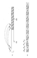
- each video stream is divided into a plurality of extents 7602A-C and 7603A-C on the optical disc 6701.
- Each extent includes one or more GOPs (Group of Pictures) and is read in a batch by the optical disk drive.
- GOPs Group of Pictures
- the extent belonging to the 2D / left-view video stream is referred to as “2D / left-view extent”
- the extent belonging to the right-view video stream is referred to as “right-view extent”.
- the 2D / left-view extent 7602A-C and the right-view extent 7603A-C are alternately arranged on the track 7601A of the optical disc 7601.
- the playback time is equal between two adjacent extents 7602A-7603A, 7602B-7603B, 7602C-7603C.
- Such arrangement of extents is referred to as “interleaved arrangement”. Extents recorded in the interleaved arrangement are used for both 3D video playback and 2D video playback as described below.
- the optical disc drive 7604A reads only the 2D / left-view extents 7602A-C from the top in the order of the extents on the optical disc 7601, while skipping reading of the right-view extents 7603A-C. Further, the video decoder 7604B sequentially decodes the extents read by the optical disc drive 7604A into video frames 7606L. Accordingly, only the left view is displayed on the display device 7607, so that the viewer can see a normal 2D video.
- the optical disk drive 7605A expresses 2D / left-view extent and right-view extent alternately from the optical disk 7601
- the data is read in the order of 7602A, 7603A, 7602B, 7603B, 7602C, and 7603C.
- the 2D / left-view video stream is sent to the left video decoder 7605L
- the right-view video stream is sent to the right video decoder 7605R.
- Each video decoder 7605L, 7605R alternately decodes each video stream into video frames 7606L, 7606R. Accordingly, the left view and the right view are alternately displayed on the display device 7608.
- the shutter glasses 7609 make the left and right lenses opaque alternately in synchronization with screen switching by the display device 7608. Accordingly, a viewer wearing the shutter glasses 7609 can see the video displayed on the display device 7608 as a 3D video.
- the interleaved arrangement of extents is used as described above. Accordingly, the recording medium can be used for both 2D video playback and 3D video playback.
- the optical disc drive 7605A performs “jump” for each recording area of the right-view extents 7603A-C, and starts from that recording area. Skip reading of data. Since data is not supplied from the optical disk drive 7604A to the buffer in the 2D playback device 7604 during the jump period, the data stored in the buffer decreases with the processing of the video decoder 7604B. Therefore, in order for 2D video to be played back seamlessly, the data amount, that is, the size of each 2D / left-view extent 7602A-C must be greater than or equal to the amount that can prevent buffer underflow during the jump period.
- the right-view extent 7603A-C is not read during the period when the 2D / left-view extent 7602A-C is being read. Therefore, during that period, the data of the right-view extents 7603A-C stored in the buffer in the 3D playback device 7605 decreases with the processing of the right video decoder 7605R. Conversely, during the period when the right-view extent 7603A-C is being read, the data of the 2D / left-view extent 7602A-C accumulated in the buffer decreases with the processing of the left video decoder 7605L.
- each of the left and right extents 7602A-C and 7603A-C is such that the data of the other extent in the buffer is depleted during the reading period of one extent. Must be more than preventable.
- optical disks include a plurality of recording layers such as so-called double-layer disks.
- a series of stream data may be recorded over two layers.
- the optical disc drive skips reading of other data or switches the recording layer by jumping. Regardless of the jump, in order to play the video seamlessly, the size of the extent must be larger than the buffer underflow during the jump period or the data of any extent can be prevented from being depleted.
- An object of the present invention is to provide a recording medium in which stream data is arranged so that an underflow does not occur in a buffer in the playback device when the playback device plays back either a stereoscopic video or a stereoscopic video.
- Another object of the present invention is to provide a playback apparatus capable of seamlessly playing back both a planar video and a stereoscopic video from the recording medium.
- the main view stream and the subview stream are recorded on the recording medium according to the embodiment of the present invention.
- the main view stream is used for playback of planar video.
- the sub-view stream is combined with the main view stream and used for reproducing stereoscopic video.
- the main view stream is divided into a plurality of main view data blocks, and the sub view stream is divided into a plurality of sub view data blocks.
- Those data blocks include a plurality of extent blocks.
- the extent block is data in which main view data blocks and subview data blocks are alternately and continuously arranged, and is referred to as one extent when a stereoscopic video is reproduced.
- the size of each extent block is the first data in the next extent block after the jump starts.
- the lower limit is a value at which the buffer of the playback device does not underflow.
- a playback apparatus includes a reading unit, a switch unit, a first read buffer, a second read buffer, and a decoding unit.
- the reading unit reads the extent block from the recording medium according to the embodiment of the present invention.
- the switch unit extracts the main view stream and the subview stream from the extent block.
- the first read buffer stores the main view stream extracted by the switch unit.
- the second read buffer stores the subview stream extracted by the switch unit.
- the decoding unit reads each stream from each read buffer and decodes it.
- the time (t) required for the decoding unit to decode all the data blocks in one extent block is equal to or greater than the sum of the following three times (t 1 , t 2 , t 3 ):
- Read unit Is the time required to read a data block excluding the first data block in one extent block (t 1 ); the next extent block after the reading unit has read the end of one extent block The time required to start reading the head of data (t 2 ); and the time required for the reading unit to read the first data block in the next extent block (t 3 ).
- the stream data is arranged on the recording medium so that the buffer in the reproducing apparatus does not cause an underflow when either the stereoscopic video or the stereoscopic video is reproduced from the recording medium. Can be easily done.
- the time required for the decoding unit to decode all the data blocks in one extent block is the time required for the reading unit to read the second data in the extent block. It is longer than the time required to read the first data block in the next extent block after starting to read the block.
- the playback device does not cause an underflow in the buffer when the video is continuously played back from two extent blocks, so that the video can be seamlessly played back from these extent blocks.
- FIG. 2 is a schematic diagram showing a data structure on a BD-ROM disc 101 shown in FIG. (A), (b), and (c) are lists of elementary streams multiplexed on the main TS, first sub-TS, and second sub-TS on the BD-ROM disc 101 shown in FIG. It is a table.
- 4 is a schematic diagram showing the arrangement of TS packets in multiplexed stream data 400.
- FIG. (B) is a schematic diagram showing a format of a TS packet sequence constituting the multiplexed stream data shown in FIG. (A) is a schematic diagram which shows the data structure of TS header 501H shown by (b).
- FIG. 3 is a schematic diagram showing details of a data structure of a video stream 800.
- FIG. 6 is a schematic diagram showing details of a method for storing a video stream 901 in a PES packet sequence 902.
- FIG. 4 is a schematic diagram showing a physical arrangement on the BD-ROM disc 101 of the main TS shown in FIG. 3 and either the first sub-TS or the second sub-TS.
- A is a schematic diagram showing an arrangement of a main TS 1401 and a sub-TS 1402 recorded individually and continuously on a certain BD-ROM disc.
- FIG. 6 is a schematic diagram showing an arrangement of view data blocks B [0], B [1], B [2],.
- (A) and (b) are examples of different extent ATC times for the dependent-view data block group D [n] and the base-view data block group B [n] recorded in an interleaved arrangement, respectively.
- N 0, 1, 2).
- FIG. 11 is a schematic diagram showing a playback path 1601 in 2D playback mode and a playback path 1602 in L / R mode for extent block groups 1301 to 1303.
- FIG. 3 is a block diagram showing a playback processing system in the playback device 102 in 2D playback mode.
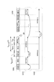
- FIG. (A) is a graph showing a change in the amount of data DA accumulated in the read buffer 1721 shown in FIG. 17 during the operation in the 2D playback mode.
- (B) is a schematic diagram showing the correspondence between the extent block 1810 to be played back and the playback path 1820 in the 2D playback mode. It is an example of a correspondence table between a jump distance S JUMP and a maximum jump time T JUMP_MAX for a BD-ROM disc.
- 3 is a block diagram showing a playback processing system in a playback device 102 in 3D playback mode.
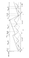
- (A) and (b) show changes in the data amounts DA1 and DA2 stored in the read buffers 2021 and 2022 shown in FIG. 20 when 3D video is seamlessly reproduced from one extent block. It is a graph which shows.
- (C) is a schematic diagram showing the correspondence between the extent block 2110 and the playback path 2120 in the 3D playback mode.
- (A) shows changes in the data amounts DA1 and DA2 accumulated in the read buffers 2021 and 2022 shown in FIG. 20 when 3D video is seamlessly reproduced from a plurality of extent blocks.
- a graph group showing the change of the sum DA1 + DA2.
- FIG. 3 is a schematic diagram showing a data structure of a PMT 2310.
- FIG. 3 is a schematic diagram showing a data structure of a first clip information file (01000.clpi) shown in FIG. 2, that is, a 2D clip information file 231.
- (A) is a schematic diagram showing a data structure of the entry map 2430 shown in FIG.
- (B) is a schematic diagram showing the source packet group 2510 belonging to the file 2D241 shown in FIG.
- (A) is a schematic diagram which shows the data structure of the offset table 2441 shown by FIG. (B) is a schematic diagram showing the effective section of the offset entry shown in (a).
- (A) is a schematic diagram which shows the data structure of the extent start point 2442 shown by FIG. (B) is a schematic diagram showing the data structure of the extent start point 2720 included in the second clip information file (02000.clpi) shown in FIG.
- (C) is a schematic diagram showing base view data blocks B [0], B [1], B [2],... Extracted from the first file SS 244A by the playback device 102 in the L / R mode.
- (D) is a schematic diagram showing the correspondence between right-view extents EXT2 [0], EXT2 [1],... Belonging to the first file DEP (02000.m2ts) 242 and the SPN2722 indicated by the extent start point 2720.
- (E) is a schematic diagram showing a correspondence relationship between extents SSEXTSS [0] belonging to the first file SS244A and extent blocks on the BD-ROM disc 101.
- FIG. 10 is a schematic diagram showing a correspondence relationship between one extent block 2800 recorded on the BD-ROM disc 101 and each extent group of a file 2D 2810, a file base 2811, a file DEP 2812, and a file SS 2820.
- Fig. 40 is a schematic diagram showing an example of entry points set in a base-view video stream 2910 and a dependent-view video stream 2920. It is a schematic diagram which shows the data structure of a 2D playlist file.
- FIG. 31 is a schematic diagram showing a data structure of PI # N shown in FIG. 30.
- (A) and (b) are schematic diagrams showing the relationship between the two playback sections 3201 and 3202 to be connected when the connection condition 3104 shown in FIG.
- FIG. 31 is “5” and “6”, respectively.
- FIG. 14 is a schematic diagram showing a correspondence relationship between a PTS indicated by a 2D playlist file (00001.mpls) 221 and a portion reproduced from a file 2D (01000.m2ts) 241.
- FIG. It is a schematic diagram which shows the data structure of a 3D playlist file.
- FIG. 35 is a schematic diagram showing a data structure of an STN table SS 3430 shown in FIG. 34.
- (A), (b), and (c) are the stream registration information column 3512 of the dependent-view video stream, the stream registration information column 3513 of the PG stream, and the stream registration of the IG stream shown in FIG. 22 is a schematic diagram showing a data structure of an information column 3514.
- FIG. 14 is a schematic diagram showing a correspondence relationship between a PTS indicated by a 2D playlist file (00001.mpls) 221 and a portion reproduced from a file 2D (01000.m2ts)
- FIG. 41 is a list of SPRMs stored in a player variable storage unit 4036 shown in FIG. [Fig. 41] Fig.
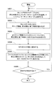
- FIG. 41 is a flowchart of 2D playlist playback processing by the playback control unit 4035 illustrated in Fig. 40.
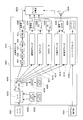
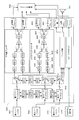
- FIG. 41 is a functional block diagram of the system target decoder 4023 shown in FIG. 40.
- 3 is a functional block diagram of a 3D playback device 4400.
- FIG. 12 is a flowchart of 3D playlist playback processing by the playback control unit 4435.
- FIG. 45 is a functional block diagram of the system target decoder 4423 shown in FIG. 44.
- FIG. 45 is a functional block diagram of a plane adder 4424 shown in FIG. 44.
- 48 is a flowchart of a cropping process performed by each cropping processing unit 4731-4734 shown in FIG.
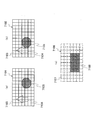
- FIG. (A), (b) is a schematic diagram which shows the cropping process by the 2nd cropping process part 4732.
- FIG. (A), (b), and (c) are 2D images represented by the PG plane data of the left view and the right view shown in FIGS. 49 (a) and 49 (b), that is, the left view and the right view, respectively. It is a schematic diagram which shows 3D image
- (A) is a schematic diagram showing extent blocks 5101 and 5102 recorded before and after the layer boundary LB.
- (B) is a schematic diagram showing a playback path 5130 in 2D playback mode and a playback path 5140 in 3D playback mode for extent blocks 5101 and 5102.
- FIG. 3 is a schematic diagram showing an arrangement 1 of data block groups recorded before and after a layer boundary LB of a BD-ROM disc 101.
- FIG. FIG. 53 is a schematic diagram showing a playback path 5310 in 2D playback mode and a playback path 5320 in 3D playback mode for the data block group of arrangement 1 shown in FIG. 52.
- 4 is a schematic diagram showing an arrangement 2 of data block groups recorded before and after a layer boundary LB of a BD-ROM disc 101.
- FIG. FIG. 55 is a schematic diagram showing a playback path 5510 in 2D playback mode and a playback path 5520 in 3D playback mode for the data block group of arrangement 2 shown in FIG. 54. 54.
- FIG. 58 is a schematic diagram showing playback paths 5801, 5802, and 5803 in 2D playback mode, L / R mode, and super mode, respectively, for the super extent block 5700 shown in FIG.
- (A) is a graph showing changes in the data amount DA accumulated in the read buffer 1721 during the operation in the 2D playback mode.
- (B) is a schematic diagram showing the correspondence between the super extent block 5910 to be played and the playback path 5920 in the 2D playback mode.
- (A) shows the amount of data DA1, DA2 stored in each read buffer 2021, 2022 when the playback device in L / R mode seamlessly plays 3D video from the super extent block 6010. It is a graph which shows a change.
- (C) is a schematic diagram showing the correspondence between the super extent block 6010 and the playback path 6020 in the L / R mode. It is a block diagram which shows the reproduction
- (A), (b), and (c) are stored in the respective read buffers 6121, 6122, and 6123 shown in FIG. 61 when 3D video is seamlessly reproduced from one super extent block.
- 6 is a graph showing changes in data amounts DA1, DA2, and DA3.
- (D) is a schematic diagram showing the correspondence between the super extent block 6210 and the playback path 6220 in the super mode.
- (A) is stored in each read buffer 6121, 6122, 6133 shown in FIG. 61 when 3D video is seamlessly reproduced continuously from two different super extent blocks 6301, 6302. It is a graph group which shows the change of data amount DA1, DA2, DA3, and the change of those sum DA1 + DA2 + DA3.
- FIG. 3 is a schematic diagram showing the arrangement of three types of data block groups recorded before and after a layer boundary LB of a BD-ROM disc 101.
- FIG. 3 is a functional block diagram of a playback device 6500 in super mode.
- FIG. FIG. 66 is a functional block diagram of the system target decoder 6524 shown in FIG. 65.
- (A) is a schematic diagram showing a playback path when the extent ATC time is different between the adjacent base-view data block and the dependent-view data block and the playback time of the video stream is different. is there.
- (B) is a schematic diagram showing a playback path when the playback time of the video stream is equal between adjacent base-view data blocks and dependent-view data blocks.
- the entry point and data block group It is a schematic diagram which shows the corresponding relationship between.
- (A) is a schematic diagram which shows the reproduction
- (B) is a schematic diagram showing a data block group 6901 recorded on a BD-ROM disc and a playback path 6902 in the L / R mode for them.
- FIG. 71 is a flowchart of a method for recording movie content on a BD-ROM disc using the recording apparatus shown in FIG. It is a functional block diagram of the integrated circuit 3 by Embodiment 3 of this invention.
- FIG. 71 is a flowchart of a method for recording movie content on a BD-ROM disc using the recording apparatus shown in FIG. It is a functional block diagram of the integrated circuit 3 by Embodiment 3 of this invention.
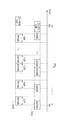
- FIG. 75 is a functional block diagram showing a typical configuration of the stream processing unit 5 shown in FIG. 74.
- FIG. 76 is a schematic diagram showing a peripheral structure when the switching unit 53 shown in FIG. 75 is a DMAC.
- FIG. 75 is a functional block diagram showing a typical configuration of the AV output unit 8 shown in FIG. 74.
- FIG. 78 is a schematic diagram showing details of a portion related to data output of the playback device 102 including the AV output unit 8 shown in FIG. 77.
- FIG. 75 is a schematic diagram showing examples (a) and (b) of the topology of the control bus and data bus in the integrated circuit 3 shown in FIG. 74.
- 75 is a flowchart of a reproduction process performed by the reproduction device 102 using the integrated circuit 3 shown in FIG.
- FIG. 81 is a flowchart showing details of each step S1-5 shown in FIG. 80.
- FIG. (A)-(c) is a schematic diagram for demonstrating the reproduction principle of 3D image
- FIG. It is a schematic diagram which shows the technique for ensuring the compatibility with a 2D reproducing
- Each part of the file 2D specified by two consecutive PIs shown in FIG. 34, each part of the file DEP specified by the corresponding SUB_PI, each part of the file SS to which these parts belong, and each file is referred to It is a schematic diagram which shows the correspondence of the extent block to be performed.
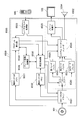
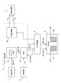
- FIG. 1 is a schematic diagram showing a home theater system using a recording medium according to Embodiment 1 of the present invention.
- This home theater system adopts a 3D video (stereoscopic video) playback method using parallax video, and particularly adopts a continuous separation method as a display method (refer to ⁇ Supplement> for details).
- this home theater system uses a recording medium 101 as a playback target, and includes a playback device 102, a display device 103, shutter glasses 104, and a remote controller 105.
- the recording medium 101 is a read-only Blu-ray Disc (registered trademark) (BD: Blu-ray Disc), that is, a BD-ROM disc.
- the recording medium 101 may be another portable recording medium, for example, a semiconductor memory device such as an optical disk, a removable hard disk drive (HDD), an SD memory card, or the like according to another method such as a DVD.
- the recording medium, that is, the BD-ROM disc 101 stores movie content by 3D video. This content includes a video stream representing each of the left view and the right view of the 3D video. The content may further include a video stream representing the depth map of the 3D video.
- These video streams are arranged on the BD-ROM disc 101 in units of data blocks as described later, and are accessed using a file structure described later.
- the video stream representing the left view or the right view is used by each of the 2D playback device and the 3D playback device to play back the content as 2D video.
- a pair of video streams representing each of the left view and the right view, or a pair of video streams representing either the left view or the right view and each of the depth maps is obtained by the 3D playback device. Used to play back as 3D video.
- the playback device 102 is equipped with a BD-ROM drive 121.
- the BD-ROM drive 121 is an optical disk drive conforming to the BD-ROM system.
- the playback apparatus 102 reads content from the BD-ROM disc 101 using the BD-ROM drive 121.
- the playback device 102 further decodes the content into video data / audio data.
- the playback device 102 is a 3D playback device, and the content can be played back as either 2D video or 3D video.
- the operation modes of the playback device 102 when playing back 2D video and 3D video are referred to as “2D playback mode” and “3D playback mode”.
- the video data includes a video frame of either a left view or a right view.
- the video data includes both left view and right view video frames.
- 3D playback mode can be further divided into left / right (L / R) mode and depth mode.
- L / R mode a pair of video frames of the left view and the right view is reproduced from a combination of video streams representing the left view and the right view.
- depth mode a video frame pair of a left view and a right view is reproduced from a combination of video streams representing either a left view or a right view and a depth map.
- the playback device 102 has an L / R mode.
- the playback device 102 may further include a depth mode.
- the playback device 102 is connected to the display device 103 via an HDMI (High-Definition Multimedia Interface) cable 122.
- the playback device 102 converts the video data / audio data into an HDMI video / audio signal, and transmits the converted video / audio data to the display device 103 via the HDMI cable 122.
- either the left view or the right view video frame is multiplexed in the video signal.
- both left-view and right-view video frames are multiplexed in the video signal in a time division manner.
- the playback device 102 further exchanges CEC messages with the display device 103 through the HDMI cable 122. As a result, the playback device 102 can inquire of the display device 103 whether or not 3D video playback is supported.
- the display device 103 is a liquid crystal display.
- the display device 103 may be a flat panel display or projector of another type such as a plasma display and an organic EL display.
- the display device 103 displays a video on the screen 131 according to the video signal, and generates a sound from a built-in speaker according to the audio signal.
- the display device 103 can support 3D video playback. During the playback of 2D video, either the left view or the right view is displayed on the screen 131. When the 3D video is reproduced, the left view and the right view are alternately displayed on the screen 131.
- the display device 103 includes a left / right signal transmission unit 132.
- the left / right signal transmitting unit 132 transmits the left / right signal LR to the shutter glasses 104 by infrared rays or wirelessly.
- the left / right signal LR indicates whether the video currently displayed on the screen 131 is the left view or the right view.
- the display device 103 detects frame switching by identifying a left-view frame and a right-view frame from a control signal accompanying the video signal.
- the display device 103 further causes the left / right signal transmission unit 132 to change the left / right signal LR in synchronization with the detected frame switching.
- the shutter glasses 104 include two liquid crystal display panels 141L and 141R and a left / right signal receiving unit 142.
- the liquid crystal display panels 141L and 141R constitute left and right lens portions.
- the left / right signal receiving unit 142 receives the left / right signal LR and sends signals to the left and right liquid crystal display panels 141L and 141R according to the change.
- Each of the liquid crystal display panels 141L and 141R transmits or blocks light uniformly in its entirety according to the signal.
- the left / right signal LR indicates left-view display
- the left-eye liquid crystal display panel 141L transmits light
- the right-eye liquid crystal display panel 141R blocks light.
- the left / right signal LR indicates a right view display.
- the two liquid crystal display panels 141L and 141R alternately transmit light in synchronization with the frame switching.
- the left view is reflected only in the viewer's left eye
- the right view is reflected only in the right eye.
- the viewer perceives the difference between the images shown in each eye as binocular parallax with respect to the same stereoscopic object, so that the video looks stereoscopic.
- the remote control 105 includes an operation unit and a transmission unit.
- the operation unit includes a plurality of buttons. Each button is associated with each function of the playback device 102 or the display device 103, such as turning on / off the power or starting or stopping playback of the BD-ROM disc 101.
- the operation unit detects pressing of each button by the user, and transmits the identification information of the button to the transmission unit by a signal.
- the transmission unit converts the signal into an infrared or wireless signal IR and sends the signal IR to the playback device 102 or the display device 103.
- each of the playback device 102 and the display device 103 receives the signal IR, specifies a button indicated by the signal IR, and executes a function associated with the button. In this way, the user can remotely operate the playback device 102 or the display device 103.
- FIG. 2 is a schematic diagram showing a data structure on the BD-ROM disc 101.
- a BCA (BursturCutting Area) 201 is provided at the innermost periphery of the data recording area on the BD-ROM disc 101. Access to the BCA is permitted only by the BD-ROM drive 121, and access by the application program is prohibited. Thereby, the BCA 201 is used for copyright protection technology.
- tracks extend spirally from the inner periphery to the outer periphery.
- the track 202 is schematically drawn in the horizontal direction. The left side represents the inner periphery of the disc 101, and the right side represents the outer periphery.
- the track 202 includes a lead-in area 202A, a volume area 202B, and a lead-out area 202C in order from the inner periphery.
- the lead-in area 202A is provided immediately outside the BCA 201.
- the lead-in area 202A includes information necessary for accessing the volume area 202B by the BD-ROM drive 121, such as the size and physical address of data recorded in the volume area 202B.
- the lead-out area 202C is provided at the outermost periphery of the data recording area and indicates the end of the volume area 202B.
- the volume area 202B includes application data such as video and audio.
- the volume area 202B is divided into small areas 202D called “sectors”.
- the sector size is common, for example, 2048 bytes.
- Each sector 202D is assigned a serial number in order from the tip of the volume area 202B. This serial number is called a logical block number (LBN) and is used as a logical address on the BD-ROM disc 101.
- LBN logical block number
- the logical address is substantially equal to the physical address. In particular, in a region where LBN is continuous, physical addresses are also substantially continuous. Therefore, the BD-ROM drive 121 can continuously read data from sectors having consecutive LBNs without causing the optical pickup to seek.
- the data recorded in the volume area 202B is managed by a predetermined file system.
- UDF Universal Disc Format
- the file system may be ISO 9660.
- the data recorded in the volume area 202B is expressed in a directory / file format (see ⁇ Supplement> for details). That is, these data can be accessed in directory units or file units.
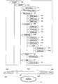
- FIG. 2 further shows the directory / file structure of the data stored in the volume area 202B of the BD-ROM disc 101.
- a BD movie (BDMV: BD Movie) directory 210 is placed immediately under a root (ROOT) directory 203.
- An index file (index.bdmv) 211 and a movie object file (MovieObject.bdmv) 212 are placed immediately below the BDMV directory 210.
- the index file 211 is information for managing the entire content recorded on the BD-ROM disc 101.
- the information includes information for causing the playback device 102 to recognize the content, and an index table.
- the index table is a correspondence table between titles constituting the content and programs for controlling the operation of the playback device 102.
- the program is called “object”.
- Object types include movie objects and BD-J (BD Java (registered trademark)) objects.
- the movie object file 212 generally includes a plurality of movie objects. Each movie object includes a sequence of navigation commands.
- the navigation command is a control command for causing the playback device 102 to execute playback processing similar to playback processing by a general DVD player.
- Types of navigation commands include, for example, an instruction to read a playlist file corresponding to a title, an instruction to reproduce an AV stream file indicated by the playlist file, and an instruction to transition to another title.
- the navigation command is written in an interpreted language, and is interpreted by an interpreter incorporated in the playback apparatus 102, that is, a job control program, and causes the control unit to execute a desired job.
- a navigation command consists of an opcode and an operand.
- the opcode indicates the type of operation to be performed by the playback apparatus 102, such as title branching, playback, and computation.
- the operand indicates identification information of the operation target such as a title number.
- the control unit of the playback device 102 calls each movie object in accordance with a user operation, and executes navigation commands included in the movie object in the order of the columns.
- the playback device 102 first displays a menu on the display device 103 and allows the user to select a command, as in a general DVD player.
- the playback device 102 dynamically changes the progress of the video to be played back, such as starting / stopping playback of the title and switching to another title.
- playlist directory 220 the playlist (PLAYLIST) directory 220, clip information (CLIPINF) directory 230, stream (STREAM) directory 240, BD-J object (BDJO: BD
- Object) are directly under the BDMV directory 210.
- a directory 250 and a Java archive (JAR: Java Archive) directory 260 are placed.
- AV stream files (01000.m2ts) 241, (02000.m2ts) 242, (03000.m2ts) 243, and a stereoscopic interleaved file (SSIF: StereoscopicSInterleaved File) Directory 244 is located.
- SSIF StereoscopicSInterleaved File
- AV stream file refers to an image content recorded on the BD-ROM disc 101 and arranged in a file format determined by the file system.
- the substance of video content generally means various stream data representing video, audio, subtitles, etc., that is, stream data in which elementary streams are multiplexed.
- the multiplexed stream data is roughly classified into a main transport stream (TS) and a sub-TS depending on the type of the built-in primary video stream.
- TS main transport stream
- sub-TS depending on the type of the built-in primary video stream.
- Main TS refers to multiplexed stream data including a base-view video stream as a primary video stream.
- a “base-view video stream” refers to a video stream that can be played back independently and represents 2D video. The base view is also called “main view”.
- Sub TS refers to multiplexed stream data including a dependent-view video stream as a primary video stream.
- a “dependent-view video stream” refers to a video stream that requires a base-view video stream for playback and represents 3D video in combination with the base-view video stream. The dependent view is also referred to as a “subview”.
- the types of dependent-view video streams include a right-view video stream, a left-view video stream, and a depth map stream.
- the “right-view video stream” is a video that represents a right view of the 3D video when the 2D video represented by the base-view video stream is used as a left view of the 3D video by a playback device in the L / R mode. ⁇ Used as a stream.
- the “left-view video stream” is the opposite.
- the “depth map stream” is a depth map of the 3D video when the 2D video represented by the base-view video stream is used as a projection of the 3D video onto the virtual 2D screen by the playback device in the depth mode. Used as stream data to represent.
- a depth map stream used when the base-view video stream represents a left view is called a “left-view depth map stream”, and when the base-view video stream represents a right view.
- the depth map stream to be used is referred to as a “right view depth map stream”.
- file 2D is an AV stream file used for 2D video playback in the 2D playback mode, and includes a main TS.
- file DEP file dependent
- file SS interleaved file
- “File 2D” is an AV stream file used for 2D video playback in the 2D playback mode, and includes a main TS.
- “File DEP” refers to an AV stream file including a sub-TS.
- “File SS” refers to an AV stream file including a pair of a main TS and a sub TS representing the same 3D video.
- the file SS shares its main TS with any file 2D and shares its sub-TS with any file DEP.
- the main TS can be accessed as both the file SS and the file 2D
- the sub-TS can be accessed as both the file SS and the file DEP.
- file cross-linking A mechanism for sharing a series of data recorded on the BD-ROM disc 101 in different files and making them accessible as any file is called “file cross-linking”.
- the first AV stream file (01000.m2ts) 241 is a file 2D
- the file 2D and the file DEP are placed directly under the STREAM directory 240.
- the first AV stream file, that is, the base-view video stream included in the file 2D241 represents a left view of 3D video.
- the dependent-view video stream included in the second AV stream file, that is, the first file DEP242 is a right-view video stream.
- the third AV stream file, that is, the dependent-view video stream included in the second file DEP 243 is a depth map stream.
- the fourth AV stream file (01000.ssif) 244A and the fifth AV stream file (02000.ssif) 244B are both files SS.
- the file SS is placed directly under the SSIF directory 244.
- the fourth AV stream file, that is, the first file SS 244A shares the main TS, particularly the base-view video stream, with the file 2D 241 and shares the sub-TS, particularly the right-view video stream, with the first file DEP 242.
- the fifth AV stream file, that is, the second file SS 244B shares the main TS, particularly the base-view video stream, with the file 2D 241 and shares the sub-TS, particularly the depth map stream, with the second file DEP 243.
- the “clip information file” is a file that is associated with the file 2D and the file DEP on a one-to-one basis, and particularly includes an entry map of each file.
- the “entry map” is a correspondence table between the display time of each scene represented by the file 2D or the file DEP and the address in each file in which the scene is recorded.
- a file associated with the file 2D is referred to as a “2D clip information file”
- a file associated with the file DEP is referred to as a “dependent view clip information file”.
- the corresponding dependent-view clip information file is referred to as a “right-view clip information file”.
- the corresponding dependent view clip information file is referred to as a “depth map clip information file”.
- the first clip information file (01000.clpi) 231 is a 2D clip information file and is associated with the file 2D241.
- the second clip information file (02000.clpi) 232 is a right-view clip information file and is associated with the first file DEP242.
- the third clip information file (03000.clpi) 233 is a depth map clip information file and is associated with the second file DEP243.
- a “playlist file” refers to a file that defines a playback path of an AV stream file, that is, a playback target portion of the AV stream file and a playback order thereof.
- the “2D playlist file” defines the playback path of the file 2D.
- the “3D playlist file” defines the playback path of the file 2D for the playback device in the 2D playback mode, and the playback path of the file SS for the playback device in the 3D playback mode. In the example shown in FIG.
- the first playlist file (00001.mpls) 221 is a 2D playlist file and defines the playback path of the file 2D241.
- the second playlist file (00002.mpls) 222 is a 3D playlist file, which defines the playback path of the file 2D241 for playback devices in 2D playback mode, and for playback devices in L / R mode. Defines the playback path of the first file SS 244A.
- the third playlist file (00003.mpls) 223 is a 3D playlist file, which defines the playback path of the file 2D241 for playback devices in 2D playback mode, and for playback devices in depth mode.
- the playback path of the second file SS 244B is defined.
- a BD-J object file (XXXXX.bdjo) 251 is placed.
- the BD-J object file 251 includes one BD-J object.
- the BD-J object is a bytecode program, and causes a Java virtual machine mounted on the playback device 102 to execute title playback processing and graphics video rendering processing.
- the BD-J object is described in a compiler type language such as Java language.
- the BD-J object includes an application management table and identification information of a playlist file to be referenced.
- the “application management table” is a correspondence table between a Java application program to be executed by the Java virtual machine and its execution time, that is, a life cycle.
- “Identification information of a playlist file to be referenced” is information for identifying a playlist file corresponding to a title to be reproduced.
- the Java virtual machine calls each BD-J object according to a user operation or an application program, and executes the Java application program according to an application management table included in the BD-J object. Thereby, the playback device 102 dynamically changes the progress of the video of each title to be played back, or causes the display device 103 to display the graphics video independently of the title video.
- a JAR file (YYYYY.jar) 261 is placed in the JAR directory 260.
- the JAR file 261 generally includes a plurality of Java application program bodies to be executed in accordance with the application management table indicated by the BD-J object.
- the “Java application program” is a bytecode program written in a compiler type language such as the Java language like the BD-J object.
- the types of Java application programs include those that cause the Java virtual machine to execute title playback processing and those that cause the Java virtual machine to execute graphics video rendering processing.
- the JAR file 261 is a Java archive file, and is expanded in its internal memory when it is read into the playback device 102. Thereby, a Java application program is stored in the memory.
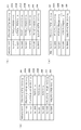
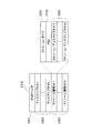
- FIG. 3A is a list of elementary streams multiplexed on the main TS on the BD-ROM disc 101.
- the main TS is a digital stream in the MPEG-2 transport stream (TS) format and is included in the file 2D241 shown in FIG.
- the main TS includes a primary video stream 301 and primary audio streams 302A and 302B.
- the main TS may include presentation graphics (PG) streams 303A and 303B, an interactive graphics (IG) stream 304, a secondary audio stream 305, and a secondary video stream 306.
- PG presentation graphics
- IG interactive graphics
- the primary video stream 301 represents the main video of the movie
- the secondary video stream 306 represents the sub-video
- the main video means a main video of content such as a main video of a movie, for example, one displayed on the entire screen.
- the sub-picture means a picture that is displayed on the screen simultaneously with the main picture by using a picture-in-picture method, such as a picture that is displayed on a small screen in the main picture.
- Both the primary video stream 301 and the secondary video stream 306 are base-view video streams.
- the video streams 301 and 306 are encoded by a moving image compression encoding method such as MPEG-2, MPEG-4 AVC, or SMPTE VC-1.
- Primary audio streams 302A and 302B represent the main audio of a movie.
- the secondary audio stream 305 represents sub-audio that should be superimposed (mixed) with the main audio, such as sound effects accompanying the operation of the dialogue screen.
- Each audio stream 302A, 302B, 305 is AC-3, Dolby Digital Plus (Dolby Digital Plus: “Dolby Digital” is a registered trademark), MLP (Meridian Lossless Packing: registered trademark), DTS (Digital Theater System) : Registered trademark), DTS-HD, or linear PCM (Pulse Code Modulation).
- Each PG stream 303A, 303B represents a graphics video to be displayed superimposed on the video represented by the primary video stream 301, such as subtitles by graphics.
- the IG stream 304 represents a graphics component for a graphics user interface (GUI) for configuring an interactive screen on the screen 131 of the display device 103 and its arrangement.
- GUI graphics user interface
- Elementary streams 301-306 are identified by a packet identifier (PID).
- PID assignment is as follows. Since one main TS includes only one primary video stream, the hexadecimal value 0x1011 is assigned to the primary video stream 301.
- any one of 0x1100 to 0x111F is assigned to the primary audio streams 302A and 302B.
- One of 0x1200 to 0x121F is allocated to the PG streams 303A and 303B.
- Any of 0x1400 to 0x141F is assigned to the IG stream 304.
- the secondary audio stream 305 is assigned one of 0x1A00 to 0x1A1F. Any number from 0x1B00 to 0x1B1F is assigned to the secondary video stream 306.
- FIG. 3B is a list of elementary streams multiplexed in the first sub-TS on the BD-ROM disc 101.
- the first sub-TS is multiplexed stream data in the MPEG-2 TS format, and is included in the first file DEP242 shown in FIG.
- the first sub-TS includes a primary video stream 311.
- the first sub-TS may include left-view PG streams 312A and 312B, right-view PG streams 313A and 313B, left-view IG stream 314, right-view IG stream 315, and secondary video stream 316.
- the primary video stream 311 is a right-view video stream.
- the primary video stream 311 represents the right view of the 3D video.
- a PG stream pair 312A + 313A, 312B + 313B of the left view and the right view represents a pair of the left view and the right view when displaying graphics video such as subtitles as 3D video.
- the IG stream pair 314 and 315 of the left view and the right view represents a pair of the left view and the right view when the graphics image of the interactive screen is displayed as a 3D image.
- the secondary video stream 316 is a right-view video stream, and when the secondary video stream 306 in the main TS represents a left view of the 3D video, the secondary video stream 316 represents the right view of the 3D video.
- PID assignment to elementary streams 311-316 is as follows.
- the primary video stream 311 is assigned 0x1012.
- any one of 0x1220 to 0x123F is assigned to the left view PG stream 312A, 312B, and the right view PG stream 313A
- One of 0x1240 to 0x125F is assigned to 313B.
- Any of 0x1420 to 0x143F is assigned to the left view IG stream 314, and any of 0x1440 to 0x145F is assigned to the right view IG stream 315.
- the secondary video stream 316 is assigned one of 0x1B20 to 0x1B3F.
- FIG. 3 is a list of elementary streams multiplexed in the second sub-TS on the BD-ROM disc 101.
- the second sub-TS is multiplexed stream data in the MPEG-2 TS format, and is included in the second file DEP243 shown in FIG.
- the second sub-TS includes a primary video stream 321.
- the second sub-TS may include depth map PG streams 323A and 323B, depth map IG stream 324, and secondary video stream 326.
- the primary video stream 321 is a depth map stream and represents 3D video in combination with the primary video stream 301 in the main TS.
- Depth map PG streams 323A and 323B are PG streams representing the depth map of the 3D video when the 2D video represented by the PG streams 323A and 323B in the main TS is used as a projection of the 3D video onto a virtual 2D screen.
- Used as The depth map IG stream 324 is used as an IG stream representing the depth map of the 3D video when the 2D video represented by the IG stream 304 in the main TS is used as a projection of the 3D video onto the virtual 2D screen.
- the secondary video stream 326 is a depth map stream, and represents 3D video in combination with the secondary video stream 306 in the main TS.
- PID assignment to the elementary streams 321 to 326 is as follows.
- the primary video stream 321 is assigned 0x1013.
- any one of 0x1260 to 0x127F is assigned to the depth map PG streams 323A and 323B.
- Any one of 0x1460 to 0x147F is assigned to the depth map IG stream 324.
- the secondary video stream 326 is assigned one of 0x1B40 to 0x1B5F.
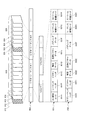
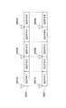
- FIG. 4 is a schematic diagram showing the arrangement of TS packets in the multiplexed stream data 400.
- This packet structure is common to the main TS and the sub-TS.
- each elementary stream 401, 402, 403, 404 is converted into a sequence of TS packets 421, 422, 423, 424.
- each frame 401A or each field is converted into one PES (Packetized Elementary Stream) packet 411.
- PES Packetized Elementary Stream
- each PES packet 411 is generally converted into a plurality of TS packets 421.
- the audio stream 402, the PG stream 403, and the IG stream 404 are once converted into a sequence of PES packets 412, 413, and 414, and then converted into a sequence of TS packets 422, 423, and 424, respectively.
- TS packets 421, 422, 423, and 424 obtained from the elementary streams 401, 402, 403, and 404 are multiplexed on a single stream data 400 by time division.
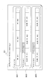
- each TS packet 501 is a packet having a length of 188 bytes.
- each TS packet 501 includes a TS payload 501P, an adaptation field (hereinafter abbreviated as an AD field) 501A, and a TS header 501H.
- the TS payload 501P and the AD field 501A are both a data area of 184 bytes in length.
- the TS payload 501P is used as a PES packet storage area.
- the AD field 501A is an area for storing stuffing bytes (that is, dummy data) when the data amount of the TS payload 501P is less than 184 bytes.
- the AD field 501A is used as an information storage area when the TS packet 501 is, for example, a PCR described later.
- the TS header 501H is a 4-byte data area.
- FIG. 5 is a schematic diagram showing a data structure of the TS header 501H.
- the TS header 501H includes a TS priority (transport_priority) 511, a PID 512, and an AD field control (adaptation_field_control) 513.
- PID512 indicates the PID of the elementary stream to which the data stored in the TS payload 501P in the same TS packet 501 belongs.
- the TS priority 511 indicates the priority of the TS packet 501 in the TS packet group in which the value indicated by the PID 512 is common.
- the AD field control 513 indicates whether each of the AD field 501A and the TS payload 501P in the TS packet 501 is present.
- the TS packet 501 does not include the AD field 501A but includes the TS payload 501P.
- the AD field control 513 indicates “2”.
- the TS packet 501 includes both the AD field 501A and the TS payload 501P.
- each source packet 502 is a 192-byte packet, and one of the TS packets 501 shown in FIG. 5B and a 4-byte header (TP_Extra_Header) 502H. Including.
- the source packet 502 is configured by adding a header 502H to the TS packet 501.
- the header 502H includes ATS (Arrival_Time_Stamp).
- ATS is time information and is used as follows: When the source packet 502 is sent from the BD-ROM disc 101 to the system target decoder in the playback device 102, the TS packet from the source packet 502 is transmitted. 502P is extracted and transferred to the PID filter in the system target decoder. The ATS in the header 502H indicates the time at which the transfer should start.
- system target decoder refers to a device that decodes multiplexed stream data for each elementary stream. Details of the system target decoder and its use of ATS will be described later.
- FIG. 5D is a schematic diagram of sectors on the volume area 202B of the BD-ROM disc 101 on which a series of source packets 502 are continuously recorded.
- the 32 source packets 502 recorded in three consecutive sectors 521, 522, and 523 are referred to as “Aligned Unit” 520.
- the playback device 102 reads source packets 502 from the BD-ROM disc 101 for each aligned unit 520, that is, 32.
- the sector groups 521, 522, 523,... are divided into 32 pieces in order from the top, and each constitutes one error correction code (ECC) block 530.
- ECC error correction code
- the BD-ROM drive 121 performs error correction processing for each ECC block 530.
- FIG. 6 is a schematic diagram showing pictures of the base-view video stream 601 and the right-view video stream 602 in order of display time.
- the base-view video stream 601 includes pictures 610, 611, 612,..., 619 (hereinafter referred to as base-view pictures), and the right-view video stream 602 includes pictures 620, 621. , 622,..., 629 (hereinafter referred to as right-view pictures).
- Each picture 610-619, 620-629 represents one frame or one field, and is compressed by a moving picture compression encoding method such as MPEG-2, MPEG-4, or AVC.
- inter-picture predictive coding For compression of each picture by the above encoding method, redundancy in the spatial direction and temporal direction of the picture is used.
- intra-picture coding coding of a picture that uses only redundancy in the spatial direction.
- inter-picture predictive coding coding of a picture that uses redundancy in the temporal direction, that is, the similarity of data between a plurality of pictures in the display order.
- inter-picture predictive coding In inter-picture predictive coding, first, another picture whose display time is before or after the picture to be coded is set as a reference picture. Next, a motion vector is detected between the picture to be encoded and the reference picture, and motion compensation is performed using the motion vector. Further, a difference value between the motion-compensated picture and the picture to be encoded is obtained, and redundancy in the spatial direction is removed from the difference value. Thus, the data amount of each picture is compressed.
- the base-view picture 610-619 is generally divided into a plurality of GOPs 631 and 6932.
- GOP refers to a sequence of a plurality of consecutive pictures starting from an I (Intra) picture.
- I picture refers to a picture compressed by intra-picture coding.
- a GOP includes a P (Predictive) picture and a B (Bidirectionally Predictive) picture in addition to an I picture.
- P picture refers to a picture compressed by inter-picture predictive coding, in which one I picture or another P picture whose display time is earlier than that is used as a reference picture.
- B picture refers to a picture compressed by inter-picture predictive coding, in which two I-pictures or P-pictures whose display time is earlier or later are used as reference pictures.
- B pictures those used as reference pictures in inter-picture predictive coding for other pictures are particularly referred to as “Br (reference B) pictures”.
- the base-view pictures in each GOP 631, 632 are compressed in the following order.
- the first base-view picture is first compressed into an I 0 picture 610.
- the subscript number indicates a serial number assigned to each picture in order of display time.
- the fourth base-view picture is compressed into a P 3 picture 613 using the I 0 picture 610 as a reference picture.
- each arrow shown in FIG. 6 indicates that the leading picture is a reference picture for the trailing picture.
- the second and third base-view pictures are compressed into Br 1 picture 611 and Br 2 picture 612 using I 0 picture 610 and P 3 picture 613 as reference pictures, respectively.
- the seventh base-view picture is compressed into a P 6 picture 616 using the P 3 picture 613 as a reference picture.
- the fourth and fifth base-view pictures are compressed into Br 4 picture 614 and Br 5 picture 615 using P 3 picture 613 and P 6 picture 616 as reference pictures, respectively.
- the top base-view picture is first compressed into an I 7 picture 617.
- the third base-view picture is compressed into a P 9 picture 619 using the I 7 picture 617 as a reference picture.
- the second base-view picture is compressed into Br 8 picture 618 using I 7 picture 617 and P 9 picture 619 as reference pictures.
- each GOP 631, 632 always includes an I picture at the head thereof, so that the base-view picture can be decoded for each GOP.
- the I 0 picture 610 is first decoded alone.
- the P 3 picture 613 is decoded using the decoded I 0 picture 610.
- the Br 1 picture 611 and the Br 2 picture 612 are decoded using the decoded I 0 picture 610 and P 3 picture 613.
- Subsequent picture groups 614, 615,... are similarly decoded.
- the base-view video stream 601 can be decoded independently, and further can be randomly accessed on a GOP basis.
- right-view pictures 620-629 are compressed by inter-picture predictive coding.
- the encoding method is different from the encoding method of the base-view pictures 610-619, and utilizes the redundancy between the left and right images in addition to the redundancy in the time direction of the images.
- the reference pictures for each right-view picture 620-629 are not only from the right-view video stream 602 but also from the base-view video stream 601 as indicated by the arrows in FIG. Is also selected.
- each right-view picture 620-629 and the base-view picture selected as its reference picture have substantially the same display time.
- the right-view pictures 620-629 have a one-to-one correspondence with the base-view pictures 610-619.
- the GOP structure is common between these pictures.
- the first right-view picture in the first GOP 631 is first compressed into a P 0 picture 620 using the I 0 picture 610 in the base-view video stream 601 as a reference picture. These pictures 610 and 620 represent the left view and the right view of the first frame of the 3D video.
- the fourth right-view picture is compressed into a P 3 picture 623 using the P 0 picture 620 and the P 3 picture 613 in the base-view video stream 601 as reference pictures.
- the second right-view picture is compressed into the B 1 picture 621 using the Br 1 picture 611 in the base-view video stream 601 as a reference picture in addition to the P 0 picture 620 and the P 3 picture 623.
- the third right-view picture is compressed into a B 2 picture 622 using the Br 2 picture 612 in the base-view video stream 601 as a reference picture in addition to the P 0 picture 620 and the P 3 picture 630. .
- a base-view picture whose display time is substantially the same as that right-view picture is used as a reference picture.
- MPEG-4 AVC / H. H.264 modified standards are known.
- MVC was established in July 2008 by JVT (Joint Video Team), a joint project between ISO / IEC MPEG and ITU-T VCEG, and is used to encode videos that can be viewed from multiple viewpoints. Is the standard.
- JVT Joint Video Team
- MVC not only the similarity in the temporal direction of video but also the similarity between videos with different viewpoints is used for inter-picture predictive coding.
- the video compression rate is higher than the predictive coding in which the video viewed from each viewpoint is individually compressed.
- the base view picture is used as a reference picture for compression of each right view picture 620-629. Therefore, unlike the base-view video stream 601, the right-view video stream 602 cannot be decoded alone. However, the difference between parallax images is generally small, that is, the correlation between the left view and the right view is high. Therefore, the right-view picture generally has a significantly higher compression rate than the base-view picture, that is, the amount of data is significantly smaller.
- FIG. 7 is a schematic diagram showing pictures of the base-view video stream 601 and the depth map stream 701 in the order of display time.
- the base view video stream 601 is similar to that shown in FIG. Therefore, the description about the detail uses the description about FIG.
- the depth map stream 701 includes depth maps 710, 711, 712,.
- the depth map 710-719 has a one-to-one correspondence with the base view picture 610-619, and represents a depth map for 2D video of one frame or one field indicated by each base view picture.
- Each depth map 710-719 is compressed by a moving image compression encoding method such as MPEG-2 or MPEG-4 AVC, similarly to the base view picture 610-619.
- inter-picture predictive coding is used in the coding method. That is, each depth map is compressed using another depth map as a reference picture.
- the top of the depth map group corresponding to the first GOP 631 is compressed into the I 0 picture 710.
- the subscript number indicates a serial number assigned to each picture in order of display time.
- the fourth depth map is compressed into a P 3 picture 713 using the I 0 picture 710 as a reference picture.
- each arrow shown in FIG. 7 indicates that the leading picture is a reference picture for the trailing picture.
- the second and third depth maps are compressed into the B 1 picture 711 and the B 2 picture 712, respectively, using the I 0 picture 710 and the P 3 picture 713 as reference pictures.
- the seventh depth map is compressed into a P 6 picture 716 using the P 3 picture 713 as a reference picture.
- the fourth and fifth depth maps are compressed into B 4 picture 714 and B 5 picture 715, respectively, using P 3 picture 713 and P 6 picture 716 as reference pictures.
- the first depth map is first compressed to the I 7 picture 717, and then the third depth map is compressed to the P 9 picture 719 using the I 7 picture 717 as a reference picture.
- the second depth map is compressed into a B 8 picture 718 using the I 7 picture 717 and the P 9 picture 719 as reference pictures.
- the depth map stream 701 is divided into GOP units similarly to the base-view video stream 601, and each GOP always includes an I picture at its head. Therefore, the depth map can be decoded for each GOP. For example, the I 0 picture 710 is first decoded alone, and then the P 3 picture 713 is decoded using the decoded I 0 picture 710. Subsequently, using the decoded I 0 picture 710 and P 3 picture 713, the B 1 picture 711 and the B 2 picture 712 are decoded. Subsequent picture groups 714, 715,... Are similarly decoded. Thus, the depth map stream 701 can be decoded alone. However, since the depth map itself is only information representing the depth of each part of the 2D video for each pixel, the depth map stream 701 cannot be used alone for video playback.
- the right-view video stream 602 and the depth map stream 701 are compressed by the same encoding method.
- the depth map stream 701 is also encoded in the MVC format.
- the playback device 102 can smoothly switch between the L / R mode and the depth mode while maintaining the encoding system constant during playback of 3D video.
- FIG. 8 is a schematic diagram showing details of the data structure of the video stream 800.
- This data structure is substantially common to the base-view video stream 601 and the dependent-view video streams 602 and 701.
- a video stream 800 is generally composed of a plurality of video sequences # 1, # 2,.
- the “video sequence” is a group of pictures 811, 812, 813, 814,... Constituting one GOP 810 individually combined with additional information such as a header.
- a combination of this additional information and each picture is called a “video access unit (VAU)”. That is, in each GOP 810, 820, one VAU # 1, # 2,.
- Each picture can be read from the video stream 800 in units of VAUs.
- FIG. 8 further shows the structure of VAU # 1831 located at the head of each video sequence in the base-view video stream.
- VAU # 1831 includes an access unit (AU) identification code 831A, a sequence header 831B, a picture header 831C, supplementary data 831D, and compressed picture data 831E.
- the second and subsequent VAU # 2 have the same structure as VAU # 1831 except that the sequence header 831B is not included.
- the AU identification code 831A is a predetermined code indicating the tip of VAU # 1831.
- the sequence header 831B is also called a GOP header, and includes an identification number of the video sequence # 1 including VAU # 1831.
- the sequence header 831B further includes information common to the entire GOP 810, such as resolution, frame rate, aspect ratio, and bit rate.
- the picture header 831C indicates a unique identification number, an identification number of the video sequence # 1, and information necessary for decoding a picture, for example, the type of encoding method.
- the supplementary data 831D includes additional information related to other than decoding of pictures, for example, character information indicating closed captions, information related to the GOP structure, and time code information. Supplementary data 831D particularly includes decoding switch information described later.
- the compressed picture data 831E includes a base view picture.
- VAU # 1831 may include any or all of padding data 831F, sequence end code 831G, and stream end code 831H as necessary.
- Padding data 831F is dummy data. By adjusting the size according to the size of the compressed picture data 831E, the bit rate of VAU # 1831 can be maintained at a predetermined value.
- the sequence end code 831G indicates that VAU # 1831 is located at the rear end of the video sequence # 1.
- the stream end code 831H indicates the rear end of the base-view video stream 800.
- FIG. 8 also shows the structure of VAU # 1832 located at the beginning of each video sequence in the dependent-view video stream.
- VAU # 1832 includes a subsequence header 832B, a picture header 832C, supplementary data 832D, and compressed picture data 832E.
- the second and subsequent VAU # 2 have the same structure as VAU # 1832 except that the subsequence header 832B is not included.
- Subsequence header 832B includes the identification number of video sequence # 1 that includes VAU # 1832.
- the subsequence header 832B further includes information common to the entire GOP 810, such as resolution, frame rate, aspect ratio, and bit rate.
- these values are equal to the values set for the corresponding GOP of the base-view video stream, that is, the values indicated by the sequence header 831B of VAU # 1831.
- the picture header 832C indicates a unique identification number, an identification number of the video sequence # 1, and information necessary for decoding a picture, for example, the type of encoding method.
- the supplementary data 832D includes additional information related to other than decoding of pictures, for example, character information indicating closed captions, information related to the GOP structure, and time code information. Supplementary data 832D particularly includes decoding switch information described later.
- the compressed picture data 832E includes a dependent view picture.
- VAU # 1932 may include any or all of padding data 832F, sequence end code 832G, and stream end code 832H as necessary.
- Padding data 832F is dummy data.
- the sequence end code 832G indicates that VAU # 1832 is located at the rear end of the video sequence # 1.
- the stream end code 832H indicates the rear end of the dependent-view video stream 800.
- each part of the VAU shown in FIG. 8 is composed of one NAL (Network Abstraction Layer) unit.
- NAL Network Abstraction Layer
- the AU identification code 831A, the sequence header 831B, the picture header 831C, the supplemental data 831D, the compressed picture data 831E, the padding data 831F, the sequence end code 831G, and the stream end code 831H are respectively an AU delimiter.
- Access Unit Delimiter SPS (Sequence Parameter Set), PPS (Picture Parameter Set), SEI (Supplemental Enhancement Information), View Component, Filler Data (Filler Data), End of Sequence (End of Sequence) and End of Stream (End of Stream).
- FIG. 9 is a schematic diagram showing details of a method for storing the video stream 901 in the PES packet sequence 902. This storage method is common to the base-view video stream and the dependent-view video stream.
- pictures are multiplexed in the coding order, not in the display time order.
- the subscript number indicates a serial number assigned to each picture in order of display time.
- the coding of P 3 picture 911 is used as reference picture I 0 picture 910, as in the coding of the B 1 picture 912 and B 2 picture 913 I 0 picture 910 and P 3 picture 911 and the reference picture Used.
- Each of these VAUs is stored in different PES packets 920, 921, 922, 923,.
- Each PES packet 920 includes a PES payload 920P and a PES header 920H.
- the VAU is stored in the PES payload 920P.
- the PES header 920H indicates the display time of a picture stored in the PES payload 920P of the same PES packet 920, that is, PTS (Presentation Time-Stamp), and the decoding time of the picture, that is, DTS (Decoding Time-Stamp). Including.
- each PES payload of a series of PES packets includes a PTS of data stored in the PES payload of the PES packet.
- FIG. 10 is a schematic diagram showing the relationship between the PTS and DTS assigned to each picture of the base-view video stream 1001 and the dependent-view video stream 1002.
- the same PTS and the same DTS are assigned to a pair of pictures representing the same frame or field of 3D video.
- the first frame or field of the 3D video is reproduced from a combination of the I 1 picture 1011 of the base-view video stream 1001 and the P 1 picture 1021 of the dependent-view video stream 1002.
- the PTS is equal and the DTS is equal in the picture pairs 1011 and 1021.
- the subscript number indicates a serial number assigned to each picture in the order of DTS.
- the P 1 picture 1021 is replaced with an I picture representing a depth map for the I 1 picture 1011.
- the second picture of the video stream 1001 and 1002 i.e., equal PTS in pairs of P 2 pictures 1012 and 1022, and DTS are equal.
- the third picture of each of the video streams 1001 and 1002 that is, the pair of Br 3 picture 1013 and B 3 picture 1023, both PTS and DTS are common. The same applies to the pair of Br 4 picture 1014 and B 4 picture 1024.
- a pair of VAUs including pictures with the same PTS and the same DTS between the base-view video stream 1001 and the dependent-view video stream 1002 is referred to as “3D VAU”.
- the base-view video stream 1001 and the dependent-view video stream 1002 are provided to the decoder in the playback device 102 in the 3D playback mode in units of 3D and VAU. It can be easily processed in parallel. This ensures that a pair of pictures representing the same frame or field of the 3D video is processed in parallel by the decoder.
- the sequence header includes the same resolution, the same frame rate, and the same aspect ratio. In particular, the frame rate is equal to the value when the base-view video stream 1001 is decoded alone in the 2D playback mode.
- FIG. 11 is a schematic diagram showing a data structure of supplementary data 831D shown in FIG. Supplementary data 831D corresponds to a kind of NAL unit “SEI” particularly in MPEG-4 AVC.
- Supplementary data 831D corresponds to a kind of NAL unit “SEI” particularly in MPEG-4 AVC.
- supplemental data 831D includes decoding switch information 1101.
- Decoding switch information 1101 is included in each VAU for both the base-view video stream and the dependent-view video stream.
- the decoding switch information 1101 is information for allowing the decoder in the playback device 102 to easily specify the VAU to be decoded next.
- the decoder alternately decodes the base-view video stream and the dependent-view video stream in units of VAU.
- each VAU preferably includes decoding switch information 1101 in addition to the DTS.
- the decryption switch information 1101 includes a next access unit type 1111, a next access unit size 1112, and a decryption counter 1113.
- the next access unit type 1111 indicates whether the VAU to be decoded next belongs to a base-view video stream or a dependent-view video stream. For example, when the value of the next access unit type 1111 is “1”, the VAU to be decoded next belongs to the base-view video stream, and when it is “2”, the dependent-view video Belongs to a stream. When the value of the next access unit type 1111 is “0”, the current VAU is located at the rear end of the stream to be decoded, and there is no VAU to be decoded next.
- the next access unit size 1112 indicates the size of the VAU to be decoded next.
- the decoder in the playback device 102 can specify the size without analyzing the structure of the VAU itself. Therefore, the decoder can easily extract the VAU from the buffer.
- the decoding counter 1113 indicates the order in which the VAU to which the decoding counter 1113 belongs should be decoded. The order is counted from the VAU that contains the I picture in the base-view video stream.
- FIG. 12 is a schematic diagram showing an example of decoding counters 1210 and 1220 assigned to the pictures of the base-view video stream 1201 and the dependent-view video stream 1202.
- the decoding counters 1210 and 1220 are alternately incremented between the two video streams 1201 and 1202. For example, “1” is assigned as the decoding counter 1210 to the VAU 1211 including the I picture in the base-view video stream 1201. Next, “2” is assigned as the decoding counter 1220 to the VAU 1221 including the P picture in the dependent-view video stream 1202 to be decoded.
- “3” is assigned as the decoding counter 1210 to the VAU 1212 including the P picture in the base-view video stream 1201 to be decoded next.
- the decoder reads and holds the decoding counter 1220 from the VAU 1222 in the decoding process of the P picture included in the second VAU 1222 of the dependent-view video stream 1202. Therefore, the decoder can predict the decoding counter 1210 of the VAU to be processed next. Specifically, since the decoding counter 1220 in the VAU 1222 including the P picture is “4”, the decoding counter 1210 of the VAU to be read next is predicted to be “5”. However, actually, since the next read VAU was the fourth VAU 1214 of the base-view video stream 1201, its decoding counter 1210 is “7”.
- the decoder can detect that one VAU is missed. Accordingly, the decoder can perform the following error processing: “For the B picture extracted from the third VAU 1223 of the dependent-view video stream 1202, the Br picture to be referred to is missing, so the decoding process is performed. skip". Thus, the decoder checks the decoding counters 1210 and 1220 for each decoding process. Accordingly, the decoder can quickly detect a VAU reading error and can execute appropriate error processing quickly. As a result, it is possible to prevent noise from being mixed into the reproduced video.
- FIG. 12 is a schematic diagram showing other examples 1230 and 1240 of decoding counters assigned to the pictures of the base-view video stream 1201 and the dependent-view video stream 1202.
- the decoding counters 1230 and 1240 are incremented separately for each video stream 1201 and 1202. Therefore, the decoding counters 1230 and 1240 are equal between a pair of pictures belonging to the same 3D ⁇ VAU.
- the decoder decodes one VAU of the base-view video stream 1201
- it can be predicted as follows: “The decoding counter 1230 has the dependent-view video stream 1202 to be decoded next. Is equal to the VAU decryption counter 1240.
- the decoder when the decoder decodes one VAU of the dependent-view video stream 1202, it can be predicted as follows: “The value obtained by adding 1 to the decoding counter 1240 is the base view to be decoded next. “Equal to the VAU decoding counter 1230 of the video stream 1201”. Therefore, the decoder can quickly detect a VAU reading error from the decoding counters 1230 and 1240 at any time, and can execute appropriate error processing quickly. As a result, it is possible to prevent noise from being mixed into the reproduced video.
- seamless playback of 3D video the physical arrangement of the base-view video stream and the dependent-view video stream on the BD-ROM disc 101 is important.
- seamless playback refers to smooth playback of video and audio from multiplexed stream data without interruption.
- FIG. 13 is a schematic diagram showing a physical arrangement on the BD-ROM disc 101 of the main TS shown in FIG. 3 and either the first sub-TS or the second sub-TS.
- the “data block” means a series of data recorded in a continuous area on the BD-ROM disc 101, that is, a plurality of physically continuous sectors.
- LBN is also continuous in each data block. Therefore, the BD-ROM drive 121 can continuously read one data block without causing the optical pickup to seek.
- the data block B [n] belonging to the main TS is referred to as “base view data block”
- the data block D [n] belonging to the sub TS is referred to as “dependent view data block”.
- a data block belonging to the first sub-TS is referred to as a “right-view data block”
- a data block belonging to the second sub-TS is referred to as a “depth map data block”.
- each data block B [n] and D [n] can be accessed as one extent in the file 2D or the file DEP. That is, the logical address of each data block can be known from the file entry of the file 2D or the file DEP (refer to ⁇ Supplement> for details).
- the file entry 1310 of the file 2D (01000.m2ts) 241 indicates the size of the base-view data block B [n] and the LBN at the tip thereof. Accordingly, each base-view data block B [n] can be accessed as the extent EXT2D [n] of the file 2D241.
- the extent EXT2D [n] belonging to the file 2D241 is referred to as “2D extent”.
- the file entry 1320 of the first file DEP (02000.m2ts) 242 indicates the size of the dependent-view data block D [n] and the LBN at the tip thereof.
- each dependent-view data block D [n] is a right-view data block and can be accessed as the extent EXT2 [n] of the first file DEP242.
- the extent EXT2 [n] belonging to the first file DEP242 is referred to as “right view extent”.
- each depth map data block can be accessed as an extent of the second file DEP (03000.m2ts) 243. is there.
- extents belonging to the second file DEP 243 are referred to as “depth map extents”.
- extents belonging to any file DEP such as right-view extents and depth map extents, are collectively referred to as “dependent view extents”.
- the data block group is continuously recorded along the track on the BD-ROM disc 101. Further, the base view data block B [n] and the dependent view data block D [n] are alternately arranged one by one. Such an arrangement of data blocks is called “interleaved arrangement”. In particular, a series of data block groups recorded in an interleaved arrangement is called an “extent block”.
- FIG. 13 shows three extent blocks 1301, 1302, and 1303. Like extent blocks 1301 and 1302 shown in FIG. 13, the extent blocks are separated by a recording area of data NAV other than multiplexed stream data.
- the BD-ROM disc 101 is a multi-layer disc, that is, when a plurality of recording layers are included, the extent blocks 1302 and 1303 shown in FIG.
- a series of multiplexed stream data is generally divided into a plurality of extent blocks.
- the playback device 102 in order for the playback device 102 to seamlessly play back video from the multiplexed stream data, it is necessary to seamlessly connect the video played back from each extent block.
- the processing required for the playback apparatus 102 for this purpose is referred to as “seamless connection between extent blocks”.
- the numbers of the two types of data blocks D [n] and B [n] are the same.
- the extent ATC time is the same for the pair D [n] and B [n] of the nth adjacent data block.
- ATC Arriv Time Clock
- the “extent ATC time” is defined by the ATC value, and the range of the ATS given to the source packet in one extent, that is, the source packet of the next extent from the ATS of the source packet of the head of the extent. Represents the time interval until ATS.
- the extent ATC time is equal to the time required to transfer all the source packets in the extent from the read buffer to the system target decoder in the playback device 102.
- the “read buffer” is a buffer memory in the playback device 102, and temporarily stores the data block read from the BD-ROM disc 101 until it is sent to the system target decoder. . Details of the read buffer will be described later.
- the VAU located at the head belongs to the same 3D / VAU, and particularly includes the head picture of the GOP representing the same 3D video.
- the tip of each right-view data block D [n] includes a P picture of the right-view video stream
- the tip of the top base-view data block B [n] is base-view video.
- the P picture of the right-view video stream represents a right view when the 2D video represented by the I picture of the base-view video stream is a left view.
- the P picture is compressed using the I picture as a reference picture, as shown in FIG. Therefore, the playback device 102 in the 3D playback mode can start playback of 3D video from any pair of data blocks D [n] and B [n]. That is, processing that requires random access to the video stream, such as dive playback, is possible.
- the dependent-view data block D [n] of the pair of adjacent data blocks D [n] and B [n] is the base-view data block. Arranged before B [n]. This is because the dependent-view data block D [n] has a smaller data amount than the base-view data block B [n], that is, the bit rate is low.
- the picture included in the nth right-view data block D [n] is included in the nth base-view data block B [n] as shown in FIG. The picture is compressed as a reference picture.
- the size S EXT2 [n] of the right-view data block D [n] is less than or equal to the size S EXT1 [n] of the base-view data block B [n]: S EXT2 [n] ⁇ S EXT1 [n].
- the data amount per pixel of the depth map that is, the number of bits of the depth value is generally larger than the amount of data per pixel of the base view picture, that is, the sum of the bit number of the color coordinate value and the ⁇ value (opacity). small.
- the main TS is different from the second sub-TS, and in addition to the primary video stream, an elementary stream such as a primary audio stream is provided. including. Therefore, the depth map data block size S EXT3 [n] is less than or equal to the size S EXT1 [n] of the base-view data block B [n]: S EXT3 [n] ⁇ S EXT1 [n].
- the playback device 102 In order to seamlessly reproduce 3D video from the BD-ROM disc 101, the playback device 102 must process the main TS and the sub TS in parallel. However, the capacity of the read buffer that can be used for the processing is generally limited. In particular, there is a limit to the amount of data that can be continuously read from the BD-ROM disc 101 into the read buffer. Therefore, the playback device 102 must read the main TS and sub-TS by dividing them into a pair of portions having the same extent ATC time.
- FIG. 14A is a schematic diagram showing the arrangement of the main TS 1401 and the sub TS 1402 recorded individually and continuously on a certain BD-ROM disc.
- the playback device 102 processes the main TS 1401 and the sub TS 1402 in parallel, as shown by solid arrows (1)-(4) in FIG.
- the main TS 1401 and the sub TS 1402 are alternately read out at a portion where the extent ATC time is equal.
- the BD-ROM drive 121 has to greatly change the read target area on the BD-ROM disc during the reading process, as indicated by the dashed arrow in FIG.
- the BD-ROM drive 121 temporarily stops the reading operation by the optical pickup and increases the rotation speed of the BD-ROM disc.
- the sector on the BD-ROM disc in which the tip of the sub-TS 1402 indicated by the arrow (2) is recorded is quickly moved to the position of the optical pickup.
- an operation for temporarily stopping the reading operation of the optical pickup and positioning the optical pickup on the next reading target area during this time is called “jump”.
- the dashed arrows shown in FIG. 14A indicate the range of each jump required during the reading process. During each jump period, the reading process by the optical pickup stops and only the decoding process by the decoder proceeds. In the example shown in FIG. 14A, the jump is excessive, and it is difficult to keep the reading process in time for the decoding process. As a result, it is difficult to reliably maintain seamless playback.
- FIG. 14 (b) shows dependent view data blocks D [0], D [1], D [2], which are alternately recorded on the BD-ROM disc 101 according to the first embodiment of the present invention. .. And base view data blocks B [0], B [1], B [2],...
- the main TS and the sub-TS are each divided into a plurality of data blocks and alternately arranged.
- the playback device 102 plays back the data blocks D [0], B [0], D as shown by arrows (1)-(4) in FIG. Read [1], B [1], ... in order from the top.
- the playback device 102 can smoothly read out the main TS and sub-TS alternately. In particular, since the jump does not occur in the reading process, seamless playback of 3D video can be surely sustained.
- the extent ATC time is the same for each dependent-view data block D [n] and the base-view data block B [n] immediately after that. For example, in the first data block pair D [0] and B [0], the extent ATC time is equal to 1 second.
- FIG. 15B shows another example of extent ATC times of the dependent-view data block group D [n] and the base-view data block group B [n] recorded in the interleaved arrangement. It is a schematic diagram. Referring to FIG. 15B, the extent ATC time is equal to 1 second in all the data blocks D [n] and B [n]. Therefore, when each data block D [n], B [n] is read into the read buffer in the playback device 102, all TS packets are read from the read buffer in the same 1 second in any data block. Sent to system target decoder.
- the dependent view data block has a higher compression ratio than the base view data block. Therefore, the speed of the decoding process of the dependent-view data block is generally lower than the speed of the decoding process of the base-view data block.
- the extent ATC time is equal, the dependent-view data block has a smaller data amount than the base-view data block. Therefore, as shown in FIGS. 15A and 15B, when the extent ATC time is equal between adjacent data blocks, the rate at which the data to be decoded is supplied to the system target decoder is Easy to maintain processing speed and balance. In other words, the system target decoder can easily synchronize the decoding process of the base-view data block and the decoding process of the dependent-view data block, especially in the dive reproduction.
- the playback device 102 in the 3D playback mode When reading the data block located at the head of each of the extent blocks 1301 to 1303 or reading the data block at the playback start position, the playback device 102 in the 3D playback mode first reads all the data blocks. Read into buffer. Meanwhile, the data block is not passed to the system target decoder. After the reading is complete, the playback device 102 passes the data block to the system target decoder in parallel with the next data block. This process is called “preload”.
- preloading is as follows.
- a base-view data block is required for decoding a dependent-view data block. Therefore, in order to maintain the buffer for holding the decoded data until the output process to the minimum capacity, it is preferable to simultaneously supply these data blocks to the system target decoder for decoding.
- the depth mode it is necessary to generate a video plane pair representing a parallax image from a pair of a base-view picture and a depth map after decoding. Therefore, in order to keep the buffer for holding the decoded data until its processing to the minimum capacity, the base view data block and the depth map data block are simultaneously supplied to the system target decoder. It is preferable to perform decryption.
- the entire data block at the beginning of the extent block or the playback start position is read in advance into the read buffer by preloading.
- the data block and the subsequent data block can be simultaneously transferred from the read buffer to the system target decoder for decoding. Further, subsequent pairs of data blocks can be simultaneously decoded by the system target decoder.
- the read buffer In preloading, the entire data block that is read first is stored in the read buffer. Accordingly, the read buffer is required to have a capacity at least equal to the size of the data block.
- the size of the data block to be preloaded should be reduced as much as possible.
- any data block pair can be selected as the reproduction start position. Therefore, in any pair of data blocks, the smaller data amount is placed first. Thereby, the capacity of the read buffer can be kept to a minimum.
- AV stream file cross-linking is realized as follows.
- the file entry 1340 of the first file SS (01000.ssif) 244A indicates each size and the LBN at the leading end of each of the extent blocks 1301 to 1303 as one extent. Accordingly, each of the extent blocks 1301-1303 can be accessed as the extents EXTSS [0], EXTSS [1], and EXTSS [2] of the first file SS 244A.
- the extents EXTSS [0], EXTSS [1], and EXTSS [2] belonging to the first file SS 244A are referred to as “extent SS”.
- Each extent SS EXTSS [0], EXTSS [1], EXTSS [2] shares the base-view data block B [n] with the file 2D241 and the right-view data block D [with the first file DEP242. share n].
- FIG. 16 is a schematic diagram showing a playback path 1601 in the 2D playback mode for the extent block groups 1301-1303.
- the second base-view data block B [1] is read, and the reading of the data NAV and the right-view data block D [1] immediately after that is skipped by the second jump J NAV . . Subsequently, reading and jumping of the base-view data block are repeated in the second and subsequent extent blocks 1302 and 1303 in the same manner.
- the jump JLY that occurs between the second extent block 1302 and the third extent block 1303 is a long jump that crosses the layer boundary LB.
- “Long jump” is a general term for jumps that have a long seek time, and specifically, jumps that exceed a predetermined threshold.
- “Jump distance” refers to the length of the area on the BD-ROM disc 101 where the read operation is skipped during the jump period. The jump distance is usually represented by the number of sectors in that portion.
- the threshold used for the definition of the long jump is defined in, for example, 40000 sectors in the BD-ROM standard. However, the threshold value depends on the type of BD-ROM disc and the performance related to the reading process of the BD-ROM drive. Long jumps specifically include focus jumps and track jumps.
- “Focus jump” is a jump accompanying switching of the recording layer, and includes a process of changing the focal length of the optical pickup.
- “Track jump” includes a process of moving the optical pickup in the radial direction of the
- FIG. 16 also shows a playback path 1602 in the L / R mode for the extent block groups 1301-1303.
- the playback device 102 in the L / R mode plays back the first file SS 244A. Therefore, as indicated by the playback path 1602 in the L / R mode, the extent blocks 1301 to 1303 are sequentially read as extents SSEXTSS [0], EXTSS [1], and EXTSS [2]. Specifically, first, data blocks D [0], B [0], D [1], and B [1] are successively read from the first extent block 1301, and immediately after that, the data NAV is read. Is skipped by the first jump J NAV .
- the playback device 102 When reading the extent blocks 1301 to 1303 as extents of the first file SS 244A, the playback device 102 starts from the file entry 1340 of the first file SS 244A and the LBN at the end of each extent SS EXTSS [0], EXTSS [1],. The size is read and passed to the BD-ROM drive 121.
- the BD-ROM drive 121 continuously reads data of that size from the LBN. In these processes, the control of the BD-ROM drive 121 is easier at the following two points (A) and (B) than the process of reading the data block group as the extents of the first file DEP242 and the file 2D241.
- the playback device 102 may refer to each extent in turn using one file entry; (B) the total number of extents to be read is substantially halved, so that the BD-ROM drive 121 The total number of LBN / size pairs to be passed is small. However, after reading the extents SSEXTSS [0], EXTSS [1],..., The playback device 102 must separate each into right-view data blocks and base-view data blocks and pass them to the decoder. A clip information file is used for the separation process. Details thereof will be described later.
- the BD-ROM drive 121 has zero zero between the trailing edge of each data block and the leading edge of the next data block. perform a sector transition J 0.
- “Zero sector transition” refers to the movement of the optical pickup between two consecutive data blocks.
- the optical pickup temporarily stops the reading operation and waits.
- zero sector transition can be regarded as “jump with jump distance equal to 0 sector”.
- the length of the zero sector transition period that is, the zero sector transition time, may include an overhead associated with error correction processing in addition to the movement time of the position of the optical pickup due to the rotation of the BD-ROM disc 101.
- “Overhead associated with error correction processing” is an extra error caused by performing error correction processing using the ECC block twice when the boundary between the two data blocks does not coincide with the boundary of the ECC block. Say good time. The entire ECC block is necessary for error correction processing. Therefore, when one ECC block is shared by two consecutive data blocks, the entire ECC block is read out and used for error correction processing in any data block read processing. As a result, every time one of these data blocks is read, extra data of up to 32 sectors is read in addition to the data block. The overhead associated with error correction processing is evaluated by the total read time of the extra data, that is, 32 [sectors] ⁇ 2048 [bytes] ⁇ 8 [bits / bytes] ⁇ 2 [times] / reading speed. By configuring each data block in units of ECC blocks, the overhead associated with error correction processing may be excluded from the zero sector transition time.
- each data block and each extent block 1301 are reproduced.
- the size of ⁇ 1303 may satisfy the following condition based on the performance of the playback device 102.
- FIG. 17 is a block diagram showing a playback processing system in the playback device 102 in the 2D playback mode.
- the playback processing system includes a BD-ROM drive 121, a read buffer 1721, and a system target decoder 1723.
- the BD-ROM drive 121 reads the 2D extent from the BD-ROM disc 101 and transfers it to the read buffer 1721 at the reading speed RUD54 .
- the read buffer 1721 is a buffer memory built in the playback device 102, and receives and accumulates 2D extents from the BD-ROM drive 121.
- the system target decoder 1723 reads the source packet from each 2D extent stored in the read buffer 1721 at an average transfer rate R EXT2D and decodes it into video data VD and audio data AD.
- the average transfer rate R EXT2D is equal to 192/188 times the average rate at which the system target decoder 1723 extracts TS packets from each source packet, and is generally different for each 2D extent.
- the maximum value R MAX2D of the average transfer rate R EXT2D is equal to 192/188 times the system rate R TS for the file 2D.
- the “system rate” means the maximum speed of the above processing by the system target decoder 1723.
- the coefficient 192/188 is equal to the ratio of the number of bytes between the source packet and the TS packet.
- the average transfer rate R EXT2D is normally expressed in bits / second, and is specifically equal to a value obtained by dividing the size of the 2D extent expressed in bits by the extent ATC time.
- the extent ATC time may be calculated as follows: First, for one 2D extent, the time interval from the ATS of the first source packet to the ATS of the last source packet is obtained. Next, the transfer time per source packet is added to the time interval. The sum is determined as the extent ATC time of the 2D extent. In this case, since the calculation of the extent ATC time does not require reference to the next extent, the calculation can be simplified. In the calculation of the extent ATC time described above, it must be considered that a wrap around occurs in the ATS.
- the read rate R UD54 is normally expressed in bits / second and is set to a value higher than the maximum value R MAX2D of the average transfer rate R EXT2D , for example, 54 Mbps: R UD54 > R MAX2D . Accordingly, underflow of the read buffer 1721 accompanying the decoding process of the system target decoder 1723 is prevented while the BD-ROM drive 121 reads one 2D extent from the BD-ROM disc 101.
- FIG. 18A is a graph showing changes in the data amount DA accumulated in the read buffer 1721 during the operation in the 2D playback mode.
- FIG. 18B is a schematic diagram showing the correspondence between the extent block 1810 to be played back and the playback path 1820 in the 2D playback mode.
- each base-view data block B [n] is read from the BD-ROM disc 101 to the read buffer 1721 as one 2D extent EXT2D [n]. Referring to (a) of FIG.
- the accumulated data amount DA is determined by the read speed R.
- the difference between UD54 and average transfer rate R EXT2D [n] increases at a rate equal to R UD54 ⁇ R EXT2D [n].
- the read / transfer operation by the BD-ROM drive 121 is actually not continuous, but intermittent, as suggested from the graph of FIG. This prevents the accumulated data amount DA from exceeding the capacity of the read buffer 1721 during the read period PR 2D [n] of each 2D extent, that is, overflow of the read buffer 1721. That is, the graph of FIG. 18A is an approximate representation of an increase or decrease that is actually stepped as a linear increase or decrease.
- a jump J 2D [n] occurs between two consecutive 2D extents EXT2D [n ⁇ 1] and EXT2D [n].
- the jump period PJ 2D [n] reading of the dependent-view data block D [n] is skipped, so that reading of data from the BD-ROM disc 101 is stopped. Accordingly, in the jump period PJ 2D [n], the accumulated data amount DA decreases at the average transfer rate R EXT2D [n].
- each jump period PJ 2D [n] the data supply from the read buffer 1721 to the system target decoder 1723 must be continued to ensure a continuous output of the decoder 1723.
- the size S EXT2D [n] of each 2D extent EXT2D [n] is read from the read period PR 2D [n] to the next jump period PJ 2D [n + 1]. It is equal to the amount of data transferred from the buffer 1721 to the system target decoder 1723. In that case, as shown in FIG. 18A, the accumulated data amount DA is less than the amount at the end of the jump period PJ 2D [n + 1] and at the start of the read period PR 2D [n]. Absent.
- each jump period PJ 2D [n] data supply from the read buffer 1721 to the system target decoder 1723 is continued, and the read buffer 1721 in particular does not cause an underflow.
- the length of the read period PR 2D [n] is equal to a value S EXT2D [n] / R UD54 obtained by dividing the size S EXT2D [n] of the 2D extent EXT2D [n] by the read speed R UD54 . Therefore, the size S EXT2D [n] of each 2D extent EXT2D [n] should satisfy the following equation (1):
- the jump time T JUMP-2D [n] is the length of the jump period PJ 2D [n] and is expressed in seconds.
- both the read speed R UD54 and the average transfer speed R EXT2D are expressed in bits / second. Therefore, in equation (1), the average transfer rate R EXT2D is divided by the number “8”, and the unit of the size S EXT2D [n] of the 2D extent is converted from bit to byte. That is, the size S EXT2D [n] of the 2D extent is expressed in bytes.
- the function CEIL () means an operation of rounding up the fractional part of the numerical value in parentheses.
- the size represented by the right side of Expression (1) is referred to as “minimum extent size of 2D extent”.
- the maximum value of the jump time T JUMP-2D [n] is limited. That is, even if the accumulated data amount DA is just before the jump period PJ 2D [n], if the jump time T JUMP ⁇ 2D [n] is too long, the jump period PJ 2D [n] There is a risk that the accumulated data amount DA reaches 0 and the read buffer 1721 underflows.
- the maximum value of the time T JUMP-2D is referred to as “maximum jump time T JUMP_MAX ”.
- FIG. 19 is an example of a correspondence table between the jump distance S JUMP and the maximum jump time T JUMP_MAX for the BD-ROM disc.
- the jump distance S JUMP is expressed in units of sectors
- the maximum jump time T JUMP_MAX is expressed in units of milliseconds.
- One sector is equal to 2048 bytes.
- the maximum jump time T JUMP_MAX are 0 ms, 250 ms, 300 ms, 350 ms, 700 ms, and 1400 ms, respectively.
- the maximum jump time T JUMP_MAX when the jump distance S JUMP is equal to 0 sector is equal to the zero sector transition time T JUMP0 .
- the zero sector transition time T JUMP0 is regarded as “0”.
- the jump time T JUMP-2D [n] to be substituted into the equation (1) is the maximum jump time T JUMP_MAX defined for each jump distance by the BD-ROM disc standard. Specifically, in the table of FIG. 19, the jump distance S JUMP between the 2D extents EXT2D [n ⁇ 1] and EXT2D [n], that is, (n + 1) from the rear end of the nth 2D extent EXT2D [n]. The maximum jump time T JUMP_MAX corresponding to the number of sectors up to the tip of the second 2D extent EXT2D [n + 1] is substituted into the equation (1) as the jump time T JUMP-2D [n].
- the jump time T JUMP ⁇ 2D [n] is limited to the maximum jump time T JUMP_MAX.
- JUMP that is, the interval between two 2D extents EXT2D [n] and EXT2D [n + 1] is also limited.
- the jump distance S JUMP when the jump time T JUMP is equal to the maximum jump time T JUMP_MAX like the maximum value of the jump distance S JUMP is referred to as “maximum jump distance S JUMP_MAX ”.
- the interval between 2D extents needs to be equal to or less than the maximum jump distance S JUMP_MAX .
- the nth 2D extent EXT2D [n] located at the rear end of the previous extent block is moved to the front end of the subsequent extent block.
- a long jump occurs until the (n + 1) th 2D extent EXT2D [n + 1] located.
- the long jump involves a recording layer switching operation such as a focus jump. Therefore, the time required for the long jump further includes the time required for the recording layer switching operation, that is, the “layer switching time” in addition to the maximum jump time T JUMP_MAX defined in the table of FIG.
- the “layer switching time” is, for example, 350 milliseconds.
- the first parameter TJ [n] represents the maximum jump time T JUMP_MAX defined for each jump distance according to the BD-ROM disc standard. For example, in the table of FIG.
- the first parameter TJ [n] is the number of sectors from the rear end of the nth 2D extent EXT2D [n] to the front end of the (n + 1) th 2D extent EXT2D [n + 1], that is, the long jump It is equal to the maximum jump time T JUMP_MAX corresponding to the jump distance S JUMP .
- the second parameter TL [n] represents a layer switching time, for example, 350 milliseconds.
- the interval between the two 2D extents EXT2D [n] and EXT2D [n + 1] that is, the interval between the two extent blocks is set to be equal to or less than the maximum jump distance S JUMP_MAX corresponding to the first parameter TJ [n].
- FIG. 20 is a block diagram showing a playback processing system in the playback device 102 in the 3D playback mode.
- the playback processing system includes a BD-ROM drive 121, a switch 2020, a pair of read buffers 2021 and 2022, and a system target decoder 2023.
- the BD-ROM drive 121 reads the extent SS from the BD-ROM disc 101 and transfers it to the switch 2020 at the reading speed RUD72 .
- the switch 2020 separates each extent SS into a base view data block and a dependent view data block. Details of the separation process will be described later.
- the base-view data block is stored in the first read buffer 2021, and the dependent-view data block is stored in the second read buffer 2022.
- Each of the read buffers 2021 and 2022 is a buffer memory built in the playback device 102, and receives and accumulates data blocks from the BD-ROM drive 121.
- the accumulated data in the second read buffer 2022 is a right-view data block in the L / R mode, and a depth map data block in the depth mode.
- the system target decoder 2023 reads the source packet from each base-view data block stored in the first read buffer 2021 at the first average transfer rate R EXT1 .
- L / R mode of the system target decoder 2023 reads source packets at the second average transfer rate R EXT2 from the right-view data blocks stored in the second read buffer 2022.
- the depth mode system target decoder 2023 reads the source packet from each depth map data block stored in the second read buffer 2022 at the third average transfer rate R EXT3 .
- the system target decoder 2023 further decodes the read base-view data block and dependent-view data block pair into video data VD and audio data AD.
- the first average transfer rate R EXT1 is referred to as “base view transfer rate”.
- the base view transfer rate R EXT1 is equal to 192/188 times the average rate at which the system target decoder 2023 extracts TS packets from each source packet in the base view data block.
- the base view transfer rate R EXT1 is generally different for each base view data block.
- the maximum value R MAX1 of the base view transfer rate R EXT1 is equal to 192/188 times the system rate R TS1 for the file 2D.
- the base-view transfer rate R EXT1 is normally expressed in bits / second, and is specifically equal to a value obtained by dividing the size of the base-view data block expressed in bits by the extent ATC time.
- the extent ATC time is equal to the time required to transfer all the source packets in the base-view data block from the first read buffer 2021 to the system target decoder 2023.
- the second average transfer rate R EXT2 is referred to as “right-view transfer rate”, and the third average transfer rate R EXT3 is referred to as “depth map transfer rate”. Furthermore, these transfer rates R EXT2 and R EXT3 are collectively referred to as “ dependent view transfer rate”. Both dependent view transfer rates R EXT2 and R EXT3 are 192/188 of the average rate at which the system target decoder 2023 extracts TS packets from each source packet in the dependent view data block. Equal to twice. Both dependent view transfer rates R EXT2 and R EXT3 are generally different for each dependent view data block.
- Light highest view transfer rate R EXT2 R MAX2 is equal to 192/188 times the system rate R TS2 for the first file DEP, the maximum value R MAX3 system rate for the second file DEP depth map transfer rate R EXT3 R TS3 Is equal to 192/188 times.
- Each dependent- view transfer rate R EXT2 , R EXT3 is usually expressed in bits / second, specifically when the size of the dependent-view data block expressed in bits is divided by the extent ATC time. Is equal to the value of The extent ATC time is equal to the time required to transfer all the source packets in each dependent view data block from the second read buffer 2022 to the system target decoder 2023.
- Read rate R UD72 is usually expressed in bits / second, first, second, and third mean transfer rate R EXT1, R EXT2, the maximum value R MAX1 of any R EXT3, R MAX2, a value higher than R MAX3, e.g. 72Mbps is set to: R UD72> R MAX1, R UD72> R MAX2, R UD72> R MAX3. This prevents underflow of the read buffers 2021 and 2022 accompanying the decoding process of the system target decoder 2023 while one extent SS is being read from the BD-ROM disc 101 by the BD-ROM drive 121. .
- FIGS. 21A and 21B are graphs showing changes in the data amounts DA1 and DA2 stored in the read buffers 2021 and 2022 when 3D video is seamlessly reproduced from one extent block 2110.
- FIG. 21C is a schematic diagram showing the correspondence between the extent block 2110 and the playback path 2120 in the 3D playback mode.
- the extent block 2110 is a data block group D [k], B [k] having an interleaved arrangement similar to that shown in FIG. 18 (b) 1810.
- K ..., n-1, n, n + 1, n + 2, .
- the entire extent block 2110 is collectively read as one extent SS. After that, the dependent-view data block and the base-view data block are separated from the extent SS by the switch 2020.
- the read / transfer operation by the BD-ROM drive 121 is not continuous, but intermittent, as suggested from the graphs of FIGS. 21A and 21B.
- the graphs of FIGS. 21A and 21B approximately represent the increase or decrease that is actually stepped as a linear increase or decrease.
- the accumulated data amount DA1 of the first read buffer 2021 is equal to the base-view transfer rate R EXT1 [n ⁇ 1] continues to decrease, and the accumulated data amount DA2 of the second read buffer 2022 decreases at the dependent- view transfer rate R EXTm [n].
- the accumulated data amount DA1 in the first read buffer 2021 Increases at a rate equal to the difference R UD72 ⁇ R EXT1 [n] between the read rate R UD72 and the base view transfer rate R EXT1 [n].
- the accumulated data amount DA2 of the second read buffer 2022 continues to decrease at the dependent view transfer rate R EXTm [n].
- the zero sector transition J 0 [2n + 1] is from the base-view data block B [n] to the next dependent-view data block D [n + 1]. Arise. As shown in FIGS.
- the accumulated data amount DA1 of the first read buffer 4021 is equal to the base-view transfer rate R EXT1 [n
- the accumulated data amount DA2 of the second read buffer 4022 continues to decrease at the dependent view transfer rate R EXTm [n].
- the dependent view data block D [n] is a right view data block.
- the size of the right view data block may be read as the size of the depth map data block, and the right view transfer rate may be read as the depth map transfer rate.
- the size S EXT1 [n] of the nth base-view data block B [n] is at least the reading period of the next base-view data block B [n + 1] from the reading period PR B [n] It is equal to the amount of data transferred from the first read buffer 2021 to the system target decoder 2023 until immediately before PR B [n + 1]. In this case, as shown in FIG. 21A, the data stored in the first read buffer 2021 immediately before the read period PR B [n + 1] of the next base-view data block B [n + 1]. The amount DA1 does not fall below the amount immediately before the read period PR B [n] of the nth base-view data block B [n].
- the length of the read period PR B [n] of the nth base-view data block B [n] is the speed of reading the size S EXT1 [n] of the base-view data block B [n]. It equals R value divided by UD72 S EXT1 [n] / R UD72.
- the length of the read period PR D [n + 1] of the (n + 1) th dependent- view data block D [n + 1] is the size S EXT2 [of the dependent- view data block D [n + 1].
- n + 1] divided by read speed R UD72 Equals to S EXT2 [n + 1] / R UD72 . Accordingly, the size S EXT1 [n] of the base-view data block B [n] should satisfy the following equation (2):
- the size represented by the right side of Expression (2) is referred to as “the minimum extent size of the base view data block”. Note that when the base-view data block is located at the rear end of the extent block 2110, the size of the data block may not satisfy the formula (2).
- the size S EXT2 [n] of the nth dependent- view data block D [n] is at least the next dependent- view data block D [n + 1] from the read period PR D [n]. ] Is equal to the amount of data transferred from the second read buffer 2022 to the system target decoder 2023 immediately before the read period PR D [n + 1]. In that case, as shown in FIG. 21B, the second read buffer 2022 is immediately before the read period PR D [n + 1] of the next dependent-view data block D [n + 1]. The accumulated data amount DA2 does not fall below the amount immediately before the read period PR D [n] of the nth dependent-view data block D [n].
- the length of the read period PR D [n] of the nth dependent- view data block D [n] is the size S EXT2 [n] of the dependent- view data block D [n]. ] Divided by read speed R UD72 , equal to S EXT2 [n] / R UD72 . Therefore, the size S EXT2 [n] of the dependent- view data block D [n] should satisfy the following equation (3):
- the size represented by the right side of Expression (3) is referred to as “the minimum extent size of the dependent-view data block”.
- the size S EXT1 [n] of the base-view data block B [n] should satisfy equation (1).
- the size S EXT1 [n] of the base-view data block B [n] is less than or equal to the lower limit value of the minimum extent size of the 2D extent. I just need it. That is, the size S EXT1 [n] satisfies the following equation (4):
- the jump time T JUMP-2D_MIN is the minimum value of the jump time required when 2D video is reproduced from the extent block 2101, and is, for example, 199 milliseconds.
- the extent ATC time T EXT [n] is equal in the pair D [n] and B [n] of the nth data block.
- T EXT [n] S EXTm [n] / R EXTm [n]. Therefore, the size S EXTm [n] of the data blocks D [n] and B [n] satisfies the following equation (5):
- FIG. 22A shows changes in the data amounts DA1 and DA2 accumulated in the read buffers 2021 and 2022 and their sum when 3D video is seamlessly reproduced continuously from a plurality of extent blocks. It is a graph group which shows the change of DA1 + DA2.
- FIG. 22B shows an M-th extent block 2201 and an (M + 1) -th extent block 2202, and their extent blocks 2201, 2202 and the 3D playback mode.
- 6 is a schematic diagram showing a correspondence relationship with a reproduction path 2220 in FIG. Referring to FIG. 22 (b), each extent block 2201, 2202 includes a dependent-view data block group D having an interleaved arrangement similar to that shown in FIG. 18 (b) 1810.
- the alternate long and short dash line graph shows the change in the data amount DA1 stored in the first read buffer 2021
- the broken line graph shows the data amount DA2 stored in the second read buffer 2022.
- the solid line graph shows the change of the sum DA1 + DA2 of both data amounts.
- the sum DA1 + DA2 actually changes finely every time one data block is read.
- the solid line graph is a linear approximation of the fine changes.
- the zero sector transition time T JUMP0 is sufficiently negligible in comparison to the length of one extent block the entire read period PR BLK [M], shown in FIG. 22 (a) the zero sector transition time T JUMP0 Is considered “0”.
- the average transfer rate R EXTSS [M] is the size of the entire M-th extent block 2201, that is, the size S EXTSS [M] of the M-th extent SS EXTSS [M] divided by the extent ATC time T EXTSS. Be evaluated.
- Such an increase in the accumulated data amounts DA1 and DA2 can be realized by designing the sizes of the data blocks D and B to be larger than the minimum extent size.
- the sum DA1 + DA2 of the accumulated data amount reaches the maximum value.
- the sum DA1 + DA2 of the accumulated data amount decreases at the average transfer rate R EXTSS [M]. Therefore, by adjusting the maximum value of the sum DA1 + DA2 of the accumulated data amount sufficiently large, underflow of both the read buffers 2021 and 2022 during the jump J [M] can be prevented. As a result, the two extent blocks 2201 and 2202 can be seamlessly connected.
- M th extent block 2201 to connect seamlessly to the (M + 1) th extent block 2202, the size of the M-th extent block 2201, i.e. M th extent SS EXTSS [M] Size S EXTSS of [M] should satisfy the following condition [7].
- Preload is performed during the read period PR D [m] of the dependent-view data block D located at the tip of the Mth extent block 2201 (the integer m is 1 or more).
- the preload period PR D [m] since the base view data block B corresponding to the dependent view data block D is not yet stored in the first read buffer 2021, the dependent view Data block D cannot be transferred from the second read buffer 2022 to the system target decoder 2023. Therefore, in the preload period PR D [m], the data of the (M ⁇ 1) th extent block is transferred from the second read buffer 2022 to the system target following the period of the jump J [M ⁇ 1] immediately before. It must be transferred to the decoder 2023.
- preloading is performed in the read period PR D [n] of the dependent-view data block D located at the tip of the (M + 1) th extent block 2202 (the integer n is m + 1 or more). Therefore, in the preload period PR D [n], the data of the Mth extent block 2201 is transferred from the second read buffer 2022 to the system target decoder 2023 following the immediately preceding jump J [M]. Must be done. Thereby, the supply of data to the system target decoder 2023 can be maintained.
- the data of the (M ⁇ 1) th extent block is transferred from the second read buffer 2022 to the system target decoder 2023.
- the data of the Mth extent block must be transferred from the second read buffer 2022 to the system target decoder 2023. I must. Therefore, in order to prevent underflow of both read buffers 2021 and 2022 during the jump J [M], the extent ATC time T EXTSS of the Mth extent SSEXTSS [M] is at least the Mth extent block 2201.
- the size S EXTSS [M] of the Mth extent SSEXTSS [M] is at least equal to the sum of the amount of data transferred from the read buffers 2021 and 2022 to the system target decoder 2023 during the period T0-T1. That's fine.
- the length of the period T0-T1 is the read period of the first dependent- view data block D from the read period PR BLK [M] of the Mth extent block 2201.
- the first dependent view data of the (M + 1) th extent block 2201 It is equal to the total t 1 + t 2 + t 3 of the length t 3 of the read period PR D [n] of the block D.
- the length of the period T0-T1 is the length of the read period PR BLK [M] of the Mth extent block 2201, the jump time T JUMP [M] of the jump J [M], and the extent block 2201, It is equal to the sum of the length differences T DIFF [M] of the preload periods PR D [n] and PR D [m] between 2202.
- the length of the read period PR BLK [M] of the Mth extent block 2201 is the value S EXTSS [M] obtained by dividing the size S EXTSS [M] of the Mth extent SSEXTSS [M] by the read speed R UD72. ] / R Equal to UD72 . Therefore, the size S EXTSS [M] of the Mth extent SS EXTSS [M] should satisfy the following equation (6):
- the size represented by the right side of Expression (6) is referred to as “the minimum extent size of the extent SS”.
- the right side of Expression (6) may be represented by an integer value in byte units, similarly to the right side of Expressions (1) to (4).
- Condition 1 2D extent size S EXT2D satisfies Expression (1).
- Condition 2 Base-view data block size S EXT1 satisfies Expression (2).
- Condition 3 The dependent- view data block size SEXT2 satisfies Expression (3).
- Condition 4 extent block size S EXTSS satisfies equation (6).
- the lower limit value of the size of each extent block is clear in addition to the lower limit value of the size of each data block.
- Easy to design This makes it easy to prevent underflow in the read buffers 2021 and 2022 in the playback device 102 when 3D video is played back from the BD-ROM disc 101.
- Condition 4 reflects the difference in the length of the preload period between extent blocks to be seamlessly connected. Thereby, it is easy to reliably realize seamless connection between the extent blocks.
- the types of TS packets included in the AV stream file include PAT (Program Association Table), PMT (Program Map Table), and PCR (in addition to those converted from the elementary stream shown in FIG. Program Clock Reference).
- PCR, PMT, and PAT are defined in the European digital broadcasting standard, and originally have a role of defining a partial transport stream constituting one program.
- the AV stream file is also defined in the same manner as the partial transport stream.
- PAT indicates the PID of the PMT included in the same AV stream file.
- the PID of the PAT itself is 0.
- the PMT includes the PID of each elementary stream representing video / audio / subtitles and the attribute information included in the same AV stream file.
- the PMT further includes various descriptors (also referred to as descriptors) regarding the AV stream file.
- the descriptor includes copy control information indicating permission / prohibition of copying of the AV stream file.
- the PCR includes information indicating the value of STC (System Time Clock) to be associated with the ATS assigned to itself.
- STC System Time Clock
- STC is a clock used as a reference for PTS and DTS by the decoder in the playback apparatus 102.
- the decoder uses PCR to synchronize the STC with the ATC.
- FIG. 23 is a schematic diagram showing the data structure of PMT2310.
- the PMT 2310 includes a PMT header 2301, a descriptor 2302, and stream information 2303.
- the PMT header 2301 indicates the length of data included in the PMT 2310.
- Each descriptor 2302 is a descriptor related to the entire AV stream file including the PMT 2310.
- the aforementioned copy control information is included in one of the descriptors 2302.
- the stream information 2303 is information regarding each elementary stream included in the AV stream file, and is assigned to a different elementary stream one by one.
- Each stream information 2303 includes a stream type 2331, a PID 2332, and a stream descriptor 2333.
- the stream type 2331 includes identification information of the codec used for compressing the elementary stream.
- PID 2332 indicates the PID of the elementary stream.
- the stream descriptor 2333 includes attribute information of the elementary stream, such as a frame rate and an aspect ratio.
- the decoder in the playback device 102 can process the AV stream file in the same manner as a partial transport stream compliant with the European digital broadcasting standard. Thereby, compatibility between the playback device for the BD-ROM disc 101 and a terminal device compliant with the European digital broadcasting standard can be ensured.
- FIG. 24 is a schematic diagram showing the data structure of the first clip information file (01000.clpi), that is, the 2D clip information file 231.
- the dependent view clip information files (02000.clpi, 03000.clpi) 232 and 233 have the same data structure.
- the data structure common to all clip information files will be described by taking the data structure of the 2D clip information file 231 as an example. Subsequently, differences in data structure between the 2D clip information file and the dependent view clip information file will be described.
- the 2D clip information file 231 includes clip information 2410, stream attribute information 2420, an entry map 2430, and 3D metadata 2440.
- the 3D metadata 2440 includes an offset table 2441 and an extent start point 2442.
- the clip information 2410 includes a system rate 2411, a playback start time 2412, and a playback end time 2413 as shown in FIG.
- the system rate 2411 defines the system rate R TS for the file 2D (01000.m2ts) 241.
- the playback device 102 in 2D playback mode transfers “TS packet” belonging to the file 2D 241 from the read buffer 1721 to the system target decoder 1723.
- the reproduction start time 2412 indicates the PTS of the top VAU of the file 2D 241, for example, the PTS of the top video frame.
- the playback end time 2412 indicates an STC value delayed by a predetermined amount from the PAU of the VAU at the rear end of the file 2D241, for example, a value obtained by adding the playback time per frame to the PTS of the last video frame.
- the stream attribute information 2420 is a correspondence table between the PID 2421 of each elementary stream included in the file 2D 241 and the attribute information 2422 as shown in FIG.
- the attribute information 2422 is different for each of the video stream, the audio stream, the PG stream, and the IG stream.
- the attribute information associated with PID 0x1011 of the primary video stream indicates the type of codec used for compression of the video stream, the resolution of each picture constituting the video stream, the aspect ratio, and the frame rate. Including.
- the attribute information associated with PID 0x1100 of the primary audio stream includes the type of codec used for compression of the audio stream, the number of channels included in the audio stream, the language, and the sampling frequency.
- the attribute information 2422 is used by the playback device 102 to initialize the decoder.
- FIG. 25 is a schematic diagram showing the data structure of the entry map 2430.
- the entry map 2430 includes a table 2500.
- the number of table 2500 is the same as the number of video streams multiplexed in the main TS, and one is assigned to each video stream.
- each table 2500 is distinguished by the PID of the video stream to which it is assigned.
- Each table 2500 includes an entry map header 2501 and an entry point 2502.
- the entry map header 2501 includes the PID associated with the table 2500 and the total number of entry points 2502 included in the table 2500.
- the entry point 2502 associates a pair of a PTS 2503 and a source packet number (SPN) 2504 one by one with a different entry point ID (EP_ID) 2505.
- the PTS 2503 is equal to the PTS of any I picture included in the PID video stream indicated by the entry map header 2501.
- the SPN 2504 is equal to the leading SPN of the source packet group in which the I picture is stored.
- SPN is a serial number assigned to the source packet group belonging to one AV stream file in order from the top. The SPN is used as an address of each source packet in the AV stream file.
- SPN means a number assigned to a source packet group belonging to the file 2D 241, that is, a source packet group constituting the main TS. Therefore, the entry point 2502 represents the correspondence between the PTS and address of each I picture included in the file 2D 241, that is, the SPN.
- Entry point 2502 may not be set for all I pictures in file 2D241. However, when the I picture is located at the beginning of the GOP and the TS packet including the beginning of the I picture is located at the beginning of the 2D extent, the entry point 2502 must be set for the I picture.
- FIG. 25 is a schematic diagram showing the source packet group 2510 belonging to the file 2D 241 that is associated with each EP_ID 2505 by the entry map 2430.
- the playback device 102 uses the entry map 2430 to identify the SPN of the source packet including the frame from the PTS of the frame representing an arbitrary scene.
- the playback device 102 refers to the file entry of the file 2D 241 and specifies the LBN of the sector (the above total number + 1) from the head of the sector group in which the 2D extent group is recorded.
- the playback device 102 designates the LBN to the BD-ROM drive 121. As a result, the base-view data block group is read out in units of aligned units in order from the LBN sector. The playback device 102 further selects a source packet indicated by the entry point of the playback start position from the aligned unit that is read first, and extracts and decodes the I picture from them. Thereafter, subsequent pictures are sequentially decoded using the previously decoded pictures. In this way, the playback device 102 can play back 2D video images after a specific PTS from the file 2D241.
- Entry map 2430 is further advantageous for efficient processing of special playback such as fast forward playback and rewind playback.
- the playback device 102 uses the file entry of the file 2D 241 to identify the LBN of the sector corresponding to each SPN.
- the playback device 102 designates each LBN to the BD-ROM drive 121. Thereby, the aligned unit is read from the sector of each LBN.
- the playback device 102 further selects a source packet indicated by each entry point from each aligned unit, extracts an I picture from them, and decodes it. Thus, the playback device 102 can selectively play back I pictures from the file 2D 241 without analyzing the 2D extent group EXT2D [n] itself.
- FIG. 26 is a schematic diagram showing a data structure of the offset table 2441.
- the offset table 2441 is information used for the cropping process by the playback device 102 in the 3D playback mode.
- “Cropping processing” refers to processing for generating a pair of plane data representing a left view and a right view from data representing a 2D video.
- “Plane data” means a two-dimensional array of pixel data, the size of which is equal to the resolution of the video frame.
- One set of pixel data consists of a combination of a color coordinate value and an ⁇ value.
- the color coordinate value is represented by an RGB value or a YCrCb value.
- the cropping target includes plane data generated from each of the PG stream, IG stream, and secondary video stream in the main TS, and image plane data generated according to the BD-J object. It is.
- the cropping process changes the position of each pixel data in the plane data in the horizontal direction. Therefore, in the plane data pair obtained by the cropping process, the display positions of the left view and the right view are shifted from the original 2D video display position to the left and right. These displacements are perceived by the viewer as binocular parallax, so that a pair of left view and right view appears as one 3D video to the viewer.
- the offset table 2441 includes a table 2610 for each PID of the PG stream, IG stream, and secondary video stream.
- Each table 2610 is a correspondence table between the PTS 2601 and the offset value 2602.
- PTS2601 represents the display time of each plane data produced
- the offset value 2602 represents the amount of horizontal displacement of each pixel data by the cropping process by the number of signed pixels. For example, a plus sign represents a rightward displacement, and a minus sign is the opposite.
- the sign of the offset value 2602 is determined depending on whether the depth of the 3D video is nearer or deeper than the screen.
- the pair 2603 of the PTS 2601 and the offset value 2602 is referred to as “offset entry”.
- FIG. 26 is a schematic diagram showing the effective section of the offset entry.
- the valid section of each offset entry is a period from the time indicated by the PTS of the offset entry to the time indicated by the PTS of the next offset entry in the time measured by the STC.
- the cropping process changes the display position of the pixel data in the plane data by the offset value of the offset entry.
- the PTS of offset entry # 1 is 180,000
- the PTS of offset entry # 2 is 270000
- the PTS of offset entry # 3 is 360000.
- the offset value “+5” of the offset entry # 1 is valid in the STC range 2604 from 180000 to 270000
- the offset entry # 2 The offset value “+3” is valid in the STC range 2605 from 270000 to 360000.
- FIG. 27A is a schematic diagram showing the data structure of the extent start point 2442.
- the “extent start point (Extent_Start_Point)” 2442 includes a base view extent ID (EXT1_ID) 2711 and an SPN 2712.
- the EXT1_ID 2711 is a serial number assigned in order from the top to each base-view data block belonging to the first file SS (01000.ssif) 244A.
- One SPN 2712 is assigned to each EXT1_ID 2711 and is equal to the SPN of the source packet located at the head of the base-view data block identified by the EXT1_ID 2711.
- the SPN is a serial number assigned in order from the top to each source packet included in the base-view data block group belonging to the first file SS 244A.
- each base-view data block B [0], B [1], B [2],... Is shared by the file 2D241 and the first file SS244A.
- a group of data blocks arranged at a place where a long jump is necessary, such as a boundary between recording layers, generally includes a base view data block belonging only to either the file 2D241 or the first file SS244A (details are modified). See example [E]). Therefore, the SPN 2712 indicated by the extent start point 2442 is generally different from the SPN of the source packet located at the tip of the 2D extent belonging to the file 2D 241.
- FIG. 27B is a schematic diagram showing the data structure of the extent start point 2720 included in the second clip information file (02000.clpi), that is, the right-view clip information file 232.
- the extent start point 2720 includes a right-view extent ID (EXT2_ID) 2721 and an SPN2722.
- EXT2_ID 2721 is a serial number assigned in order from the top to each right-view data block belonging to the first file SS 244A.
- One SPN 2722 is assigned to each EXT2_ID 2721 and is equal to the SPN of the source packet located at the front end of the right-view data block identified by the EXT2_ID 2721.
- the SPN is a serial number sequentially assigned to each source packet included in the right-view data block group belonging to the first file SS 244A.
- FIG. 27D shows the correspondence between right-view extents EXT2 [0], EXT2 [1],... Belonging to the first file DEP (02000.m2ts) 242 and the SPN2722 indicated by the extent start point 2720. It is a schematic diagram to represent. As shown in FIG. 13, the right-view data block is shared by the first file DEP242 and the first file SS244A. Therefore, as shown in FIG. 27D, each SPN 2722 indicated by the extent start point 2720 is the SPN of the source packet located at the tip of each right-view extent EXT2 [0], EXT2 [1],. be equivalent to.
- the extent start point 2442 of the 2D clip information file 231 and the extent start point 2720 of the right-view clip information file 232 are included in each extent SS when 3D video is played back from the first file SS 244A. Used to detect data block boundaries.
- FIG. 27 is a schematic diagram showing a correspondence relationship between the extent SSEXTSS [0] belonging to the first file SS244A and the extent block on the BD-ROM disc 101.
- the difference between them is equal to A (n + 1) -An.
- A0 0.
- B0 0.
- the playback device 102 in the L / R mode uses the entry map of each clip information file 231 and 232 and the extent start points 2442 and 2720 when playing back 3D video from the first file SS 244A. Thereby, the playback device 102 specifies the LBN of the sector in which the right-view data block including the frame is recorded from the PTS of the frame representing the right view of an arbitrary scene. Specifically, the playback device 102 first searches the SPN associated with the PTS from the entry map of the right view / clip information file 232, for example. Assume that the source packet indicated by the SPN is included in the third right-view extent EXT2 [2] of the first file DEP242, that is, the right-view data block D [2].
- the playback device 102 searches the SPN 2722 indicated by the extent start point 2720 of the right-view clip information file 232 for the largest “B2” below the target SPN and the corresponding EXT2_ID “2”. Subsequently, the playback device 102 searches the extent start point 2442 of the 2D clip information file 231 for the SPN 2712 value “A2” corresponding to the EXT1_ID equal to the EXT2_ID “2”. The playback device 102 further calculates the sum B2 + A2 of the retrieved SPNs. As can be understood from FIG. 27E, the sum B2 + A2 of the source packet arranged before the third right-view data block D [2] in the extent SSEXTSS [0] is obtained.
- the quotient (B2 + A2) ⁇ 192/2048 obtained by dividing the product of the sum B2 + A2 and the data amount of 192 bytes per source packet by the data amount of 2048 bytes per sector is the extent SS EXTSS [0]. It is equal to the number of sectors from the beginning to immediately before the third right-view data block D [2].
- the LBN of the sector in which the tip of the right-view data block D [2] is recorded can be specified.
- the playback device 102 specifies the LBN as described above, and then designates the LBN to the BD-ROM drive 121. Thereby, the portion of the extent SSEXTSS [0] recorded after the sector of the LBN, that is, the data block group D [2], B [2] after the third right-view data block D [2], D [3], B [3], ... are read in aligned units.
- the playback device 102 converts the (B1 + A1) th source packet and the subsequent (B2 ⁇ B1-1) source packets into a total of (B2 ⁇ B1) source packets as the second dependent view Extracted as data block D [1].
- the playback device 102 further converts the total of (A2-A1) source packets including the (A1 + B2) th source packet and the subsequent (A2-A1-1) source packets into the second base-view data block. Extract as B [1].
- the playback device 102 similarly detects the boundary between data blocks in the extent SS from the number of read source packets, and alternately extracts each data block of the dependent view and the base view. .
- the extracted base-view data block and right-view data block are passed in parallel to the system target decoder and decoded.
- the playback device 102 in the L / R mode can play back 3D video images after the specific PTS from the first file SS 244A.
- the playback apparatus 102 can actually enjoy the advantages (A) and (B) related to the control of the BD-ROM drive 121.
- FIG. 27 (c) is a schematic diagram showing base view data blocks B [0], B [1], B [2],... Extracted from the first file SS 244A by the playback device 102 in the L / R mode.
- a base-view data block group extracted from one file SS using the extent start point is called “file base”.
- each base-view extent EXT1 [0], EXT1 [1],... is referred to by extent start points 2442 and 2720 in the clip information file.
- Base view extent EXT1 [n] shares 2D extent EXT2D [n] with base view data block B [n].
- the file base includes the same main TS as file 2D.
- the base-view extent EXT1 [n] is not referenced by the file entry of any file.
- the base view extent EXT1 [n] is extracted from the extent SSEXTSS [•] in the file SS using the extent start point in the clip information file.
- the file base does not include a file entry, and an extent starting point is required to refer to the base view extent. In that sense, the file base is a “virtual file”.
- the file base is not recognized by the file system and does not appear in the directory / file structure shown in FIG.
- FIG. 28 is a schematic diagram showing a correspondence relationship between one extent block 2800 recorded on the BD-ROM disc 101 and each extent group of the file 2D2810, the file base 2811, the file DEP2812, and the file SS2820. It is.
- the base view data block B [n] belongs to the file 2D2810 as the 2D extent EXT2D [n].
- the dependent-view data block D [n] belongs to the file DEP2812 as a dependent-view extent EXT2 [n].
- the entire extent block 2800 belongs to the file SS2820 as one extent SSEXTSS [0]. Therefore, the extent SS EXTSS [0] shares the base view data block B [n] with the 2D extent EXT2D [n], and the dependent view extent EXT2 [n] with the dependent view data block. Share block D [n]. After the extent SS EXTSS [0] is read by the playback device 102, it is separated into a dependent-view data block D [n] and a base-view data block B [n]. Those base-view data blocks B [n] belong to the file base 2811 as base-view extents EXT1 [n].
- the boundary between the base view extent EXT1 [n] and the dependent view extent EXT2 [n] in the extent SS EXTSS [0] is a clip information file associated with each of the file 2D2810 and the file DEP2812. It is specified using the extent starting point.
- the dependent view clip information file has the same data structure as the 2D clip information file shown in FIG. Therefore, in the following description, the difference between the dependent-view clip information file and the 2D clip information file will be referred to, and the description of the similar points will be referred to the above description.
- the dependent view clip information file differs from the 2D clip information file mainly in the following three points (i), (ii), and (iii): (i) Conditions are imposed on the stream attribute information; ii) A condition is imposed on the entry point; (iii) 3D metadata does not include an offset table.
- the base-view video stream and the dependent-view video stream are used for playback of 3D video by the playback device 102 in the L / R mode, as shown in FIG.
- the dependent-view video stream is compressed using the base-view video stream.
- the dependent-view video stream has the same video stream attribute as the base-view video stream.
- the codec, resolution, aspect ratio, and frame rate must match between the video stream attribute information. If the codec types match, a reference relationship in encoding is established between the base-view picture and the dependent-view picture, so that each picture can be decoded. If the resolution, aspect ratio, and frame rate all match, the screen display of the left and right images can be synchronized. Therefore, those videos can be shown as 3D videos without giving the viewer a sense of incongruity.
- the dependent view clip information file entry map includes a table assigned to the dependent view video stream. Similar to the table 2500 shown in FIG. 25A, the table includes an entry map header and entry points.
- the entry map header indicates the PID of the corresponding dependent-view video stream, ie 0x1012 or 0x1013.
- Each entry point associates a pair of PTS and SPN with one EP_ID.
- the PTS of each entry point is equal to the PTS of the first picture of any GOP included in the dependent-view video stream.
- the SPN of each entry point is equal to the first SPN of the source packet group in which the picture indicated by the PTS belonging to the same entry point is stored.
- SPN means a serial number assigned in order from the top to the source packet group belonging to the file DEP, that is, the source packet group constituting the sub-TS.
- the PTS of each entry point must match the PTS of the entry point in the table assigned to the base view video stream in the entry map of the 2D clip information file. That is, whenever an entry point is set at the head of a source packet group including one of a pair of pictures included in the same 3D / VAU, the entry point is also set at the head of the source packet group including the other. Must be.
- FIG. 29 is a schematic diagram showing examples of entry points set in the base-view video stream 2910 and the dependent-view video stream 2920.
- GOPs in the same order counted from the head represent videos in the same reproduction period.
- entry points 2901B, 2903B, and 2905B are set at the heads of odd-numbered GOP # 1, GOP # 3, and GOP # 5 counted from the head.
- entry points 2901D, 2903D, and 2905D are set at the heads of the odd-numbered GOP # 1, GOP # 3, and GOP # 5 counted from the head. ing.
- the playback device 102 can immediately calculate the SPN of the playback start position in the file SS from the SPN of the corresponding entry points 2903B and 2903D when starting playback of 3D video from GOP # 3, for example.
- the playback device 102 can immediately calculate the SPN of the playback start position in the file SS from the SPN of the corresponding entry points 2903B and 2903D when starting playback of 3D video from GOP # 3, for example.
- the playback device 102 can immediately calculate the SPN of the playback start position in the file SS from the SPN of the corresponding entry points 2903B and 2903D when starting playback of 3D video from GOP # 3, for example.
- the sum of the SPNs of entry points 2903B and 2903D is reproduced in the file SS. Equal to the starting position SPN.
- the LBN of the sector in which the portion of the reproduction start position in the file SS is recorded can be calculated from the number of source packets. In this way, even in the playback of 3D video,
- FIG. 30 is a schematic diagram showing the data structure of a 2D playlist file.
- the first playlist file (00001.mpls) 221 shown in FIG. 2 has this data structure.
- the 2D playlist file 221 includes a main path 3001 and two sub paths 3002 and 3003.
- the main path 3001 is an array of play item information (PI), and defines the main playback path of the file 2D 241, that is, the playback target portion and the playback order.
- Each PI # N defines a different playback section of the main playback path with a pair of PTSs. One of the pairs represents the start time (In-Time) of the playback section, and the other represents the end time (Out-Time).
- the PI order in the main path 3001 represents the order of the corresponding playback section in the playback path.
- Each sub-path 3002, 3003 is an array of sub-play item information (SUB_PI), and defines playback paths that can accompany the main playback path of the file 2D241 in parallel.
- the reproduction path means a part different from the part of the file 2D241 represented by the main path 3001, or a part of stream data multiplexed in another file 2D and a reproduction order thereof.
- the stream data represents another 2D video to be played simultaneously with the 2D video played from the file 2D 241 according to the main path 3001.
- the other 2D video includes, for example, a sub-video in a picture-in-picture system, a browser screen, a pop-up menu, or subtitles.
- Sub-passes 3002 and 3003 are assigned serial numbers “0” and “1” in the order of registration in the 2D playlist file 221.
- the serial number is used as a sub path ID for identifying each of the sub paths 3002 and 3003.
- Each SUB_PI # M defines a playback section having a different playback path by a pair of PTSs. One of the pair represents the reproduction start time of the reproduction section, and the other represents the reproduction end time.
- the order of SUB_PI in each of the sub-paths 3002 and 3003 represents the order of the corresponding playback section in the playback path.
- FIG. 31 is a schematic diagram showing the data structure of PI # N.
- PI # N includes reference clip information 3101, playback start time (In_Time) 3102, playback end time (Out_Time) 3103, connection condition 3104, and stream selection table (hereinafter STN (Stream Number)).
- STN Stream Number
- the reference clip information 3101 is information for identifying the 2D clip information file 231.
- the reproduction start time 3102 and the reproduction end time 3103 indicate the PTSs at the front end and the rear end of the reproduction target portion of the file 2D241.
- connection condition 3104 connects the video in the playback section specified by the playback start time 3102 and the playback end time 3103 to the video in the playback section specified by the previous PI # (N ⁇ 1). Specify the conditions for when.
- the STN table 3105 represents a list of elementary streams that can be selected from the file 2D241 by the decoder in the playback device 102 between the playback start time 3102 and the playback end time 3103.
- the SUB_PI data structure is common to the PI data structure shown in FIG. 31 in that it includes reference clip information, a playback start time, and a playback end time.
- the playback start time and playback end time of SUB_PI are represented by the same values on the time axis as those of PI.
- the SUB_PI further includes a field called “SP connection condition”.
- the SP connection condition has the same meaning as the PI connection condition.
- connection condition (hereinafter abbreviated as CC) 3104 can take, for example, three values of “1”, “5”, and “6”.
- CC3104 is “1”
- the video reproduced from the portion of the file 2D241 defined by PI # N is the same as the video reproduced from the portion of the file 2D241 defined by the immediately preceding PI # (N ⁇ 1). Need not be seamlessly connected.
- CC3104 is “5” or “6”, both of the videos must be seamlessly connected.
- 32 (a) and 32 (b) are schematic diagrams showing the relationship between two playback sections 3201 and 3202 to be connected when CC3104 is “5” and “6”, respectively.
- PI # (N ⁇ 1) defines the first part 3201 of the file 2D241
- PI # N defines the second part 3202 of the file 2D241.
- STC may be interrupted between two PI # (N ⁇ 1) and PI # N. That is, PTS # 1 at the rear end of the first portion 3201 and PTS # 2 at the front end of the second portion 3202 may be discontinuous.
- some constraints must be met.
- the portions 3201 and 3202 must be created so that the decoder can continue the decoding process smoothly. Furthermore, the last frame of the audio stream included in the first portion 3201 must overlap the first frame of the audio stream included in the second portion 3202.
- CC3104 is “6”
- the first part 3201 and the second part 3202 must be able to be handled as a series of parts in the decoding process of the decoder. . That is, both the STC and the ATC must be continuous between the first portion 3201 and the second portion 3202.
- the SP connection condition is “5” or “6”
- both the STC and the ATC must be continuous between the parts of the file 2D defined by two adjacent SUB_PIs.
- the STN table 3105 is an array of stream registration information.
- the “stream registration information” is information individually indicating elementary streams that can be selected as a playback target from the main TS between the playback start time 3102 and the playback end time 3103.
- a stream number (STN) 3106 is a serial number individually assigned to the stream registration information, and is used by the playback apparatus 102 to identify each elementary stream.
- the STN 3106 further represents the priority of selection among elementary streams of the same type.
- the stream registration information includes a stream entry 3109 and stream attribute information 3110.
- the stream entry 3109 includes stream path information 3107 and stream identification information 3108.
- the stream path information 3107 is information indicating the file 2D to which the selected elementary stream belongs.
- the file 2D corresponds to the 2D clip information file indicated by the reference clip information 3101.
- Either the playback start time or playback end time specified by the SUB_PI is included in the period from the playback start time 3102 specified by PI including the STN table 3105 to the playback end time 3103.
- the stream identification information 3108 indicates the PID of the elementary stream multiplexed in the file 2D specified by the stream path information 3107.
- the elementary stream indicated by this PID can be selected between the reproduction start time 3102 and the reproduction end time 3103.
- Stream attribute information 3110 represents attribute information of each elementary stream. For example, each attribute information of an audio stream, a PG stream, and an IG stream indicates a language type.
- FIG. 33 is a schematic diagram showing the correspondence between the PTS indicated by the 2D playlist file (00001.mpls) 221 and the portion reproduced from the file 2D (01000.m2ts) 241.
- PI # 1 defines PTS # 1 indicating the playback start time IN1 and PTS # 2 indicating the playback end time OUT1.
- the reference clip information of PI # 1 indicates a 2D clip information file (01000.clpi) 231.
- the playback device 102 first reads PTS # 1 and # 2 from PI # 1.
- the playback device 102 refers to the entry map of the 2D clip information file 231 and searches for the SPNs # 1 and # 2 in the file 2D241 corresponding to the PTSs # 1 and # 2. Subsequently, the playback device 102 calculates the number of sectors corresponding to each from SPN # 1, # 2. The playback device 102 further uses the number of sectors and the file entry of the file 2D 241 to use the LBN at the end of the sector group P1 in which the 2D extent group EXT2D [0],... EXT2D [n] to be played back is recorded. # 1 and LBN # 2 at the rear end are specified.
- the playback device 102 designates the range from LBN # 1 to LBN # 2 to the BD-ROM drive 121. Thereby, the source packet group belonging to the 2D extent group EXT2D [0],..., EXT2D [n] is read from the sector group P1 in the range. Similarly, a pair of PTS # 3 and # 4 indicated by PI # 2 is first converted into a pair of SPN # 3 and # 4 using the entry map of the 2D clip information file 231. Next, the pair of SPN # 3 and # 4 is converted into the pair of LBN # 3 and # 4 using the file entry of the file 2D241.
- the source packet group belonging to the 2D extent group is read from the sector group P2 in the range from LBN # 3 to LBN # 4. Conversion from PTS # 5, # 6 pair indicated by PI # 3 to SPN # 5, # 6 pair, conversion from SPN # 5, # 6 pair to LBN # 5, # 6 pair, and LBN # The reading of the source packet group from the sector group P3 in the range from 5 to LBN # 6 is the same.
- the playback device 102 can play back 2D video from the file 2D241 according to the main path 3001 of the 2D playlist file 221.
- the 2D playlist file 221 may include an entry mark 3301.
- An entry mark 3301 indicates a point in time on the main path 3001 where playback should actually start. For example, as shown in FIG. 33, a plurality of entry marks 3301 may be set for PI # 1.
- the entry mark 3301 is used for searching for a playback start position, particularly in cue playback. For example, when the 2D playlist file 221 defines the playback path of a movie title, an entry mark 3301 is added to the beginning of each chapter. Thereby, the playback device 102 can play back the movie title for each chapter.
- FIG. 34 is a schematic diagram showing the data structure of a 3D playlist file.
- the second playlist file (00002.mpls) 222 shown in FIG. 2 has this data structure.
- the 3D playlist file 222 includes a main path 3401, a sub path 3402, and extended data 3403.
- the main path 3401 defines the reproduction path of the main TS shown in FIG. Therefore, the main path 3401 is equal to the main path 3001 of the 2D playlist file 221 shown in FIG.
- the playback device 102 in the 2D playback mode can play back 2D video from the file 2D241 according to the main path 3001 of the 3D playlist file 222.
- the sub-path 3402 defines the reproduction path of the sub-TS shown in FIGS. 3B and 3C, that is, the reproduction path of either the first file DEP242 or the second file DEP243.
- the data structure of the sub path 3402 is the same as the data structure of the sub paths 3002 and 3003 of the 2D playlist file 241 shown in FIG. Therefore, for the details of the similar data structure, particularly the details of the data structure of SUB_PI, the description using FIG. 30 is used.
- Subpath 3402 corresponds to PI # N in the main path 3401 on a one-to-one basis. Furthermore, the playback start time and playback end time specified by each SUB_PI # N are equal to the playback start time and playback end time specified by the corresponding PI # N, respectively.
- Subpath 3402 additionally includes subpath type 3410. “Sub-path type” generally indicates whether or not the reproduction processing should be synchronized between the main path and the sub-path. In the 3D playlist file 222, the sub-path type 3410 particularly indicates the type of 3D playback mode, that is, the type of dependent-view video stream to be played according to the sub-path 3402. In FIG.
- the value of the sub-path type 3410 is “3D ⁇ L / R”, so that the 3D playback mode is the L / R mode, that is, the right-view video stream is to be played back. Show.
- the subpath type 3410 indicates that when the value is “3D depth”, the 3D playback mode is the depth mode, that is, the depth map stream is the playback target.
- the playback device 102 in the 3D playback mode detects that the value of the subpath type 3410 is “3D ⁇ L / R” or “3D depth”
- the playback device 102 follows the playback processing according to the main path 3401 and the subpath 3402. Synchronize with the playback process.
- FIG. 85 shows each part of the file 2D specified by two consecutive PIs, each part of the file DEP specified by the corresponding SUB_PI, each part of the file SS to which these parts belong, and extents referenced by each file.
- -It is a schematic diagram which shows the correspondence of a block.
- the integer N is 1 or more
- the integer k is 0 or more.
- the integers k, n, q, and s are larger in that order.
- the integer m is 1 greater than the integer k
- the integer p is 1 greater than the integer n
- PI # (N-1) defines the first part 8511 of file 2D8510
- PI # N defines the second part 8512 of file 2D8510.
- SUB_PI # (N-1) corresponding to PI # (N-1) defines the first part 8521 of the file DEP8520
- SUB_PI # N corresponding to PI # N defines the second part 8522 of the file DEP8520.
- the first parts 8511 and 8521 of each file 8510 and 8520 belong to the first part 8531 of the file SS8530
- the second parts 8512 and 8522 of each file 8510 and 8520 belong to the second part 8532 of the file SS8530.
- 2D extents EXT2D [0],..., EXT2D [k] in the first portion 8511 of the file 2D8510 are the extent SSEXTSS [0] in the first portion 8531 of the file SS8530 and the extent block 8501.
- B [k] are shared (integer k is 0 or more).
- the dependent view extents EXT2 [0],..., EXT2 [k] in the first portion 8521 of the file DEP8520 are the extent SSEXTSS [0] in the first portion 8531 of the file SS8530 and the extent block 8501.
- the dependent-view data blocks D [0], ..., D [k] are shared.
- connection condition (CC) of PI # N is “5” or “6”
- the first portion 8511 and the second portion 8512 of the file 2D 8510 are seamlessly connected.
- the SPCC of the corresponding SUB_PI # N is also “5” or “6”.
- the first portion 8521 and the second portion 8522 of the file DEP8520 are seamlessly connected.
- the second and subsequent extent blocks 8502 except for the first extent block 8501 may satisfy the above condition 4.
- the first dependent-view data block D [0] in the first extent block 8501 is sufficient. If it is designed to a large size, it can be easily realized.
- the second to last extent blocks 8503 except for the last extent block 8504 may satisfy the above condition 4.
- the extended data 3403 is a part that is interpreted only by the playback device 102 in the 3D playback mode, and is ignored by the playback device 102 in the 2D playback mode.
- the extension data 3403 specifically includes an extension stream selection table 3430.
- the “extended stream selection table (STN_table_SS)” (hereinafter abbreviated as STN table SS) is an array of stream registration information to be added to the STN table indicated by each PI in the main path 3401 in the 3D playback mode. This stream registration information indicates an elementary stream that can be selected as a playback target from the sub-TS.
- FIG. 35 is a schematic diagram showing the data structure of the STN table SS 3430.
- the STN table SS 3430 includes stream registration information columns 3501, 3502, 3503,.
- the stream registration information columns 3501, 3502, 3503,... Individually correspond to the PIs # 1, # 2, # 3,... In the main path 3401. Is used in combination with the stream registration information sequence included in.
- a stream registration information column 3501 for each PI includes a popup period offset (Fixed_offset_during_Popup) 3511, a dependent-view video stream registration information column 3512, a PG stream stream registration information column 3513, and an IG stream stream registration information. Includes column 3514.
- the pop-up period offset 3511 indicates whether or not the pop-up menu is played from the IG stream.
- the playback device 102 in the 3D playback mode changes the display mode (presentation mode) between the video plane and the PG plane according to the value of the offset 3511.
- the BD display mode is selected as the display mode of the video plane, and the 2-plane mode or 1 plane + offset mode is selected as the display mode of the PG plane.
- the BB display mode is selected as the video plane display mode, and the 1 plane + zero offset mode is selected as the display mode of the PG plane.
- the playback device 102 alternately outputs plane data decoded from the video streams of the left view and the right view. Accordingly, since the left view frame and the right view frame represented by the video plane are alternately displayed on the screen of the display device 103, the viewer can see them as a 3D image.
- the playback device 102 maintains the operation mode in the 3D playback mode (particularly, maintains the frame rate at the value at the time of 3D playback, for example, 48 frames / second), the base view video, Only the plain data decoded from the stream is output twice per frame. Accordingly, since only one of the left view and right view frames is displayed on the screen of the display device 103, the viewer can only see them as 2D video.
- the playback device 102 uses the graphics plane data of the left view and right view from each graphics stream. Are decoded and output alternately.
- “1 plane + offset mode” the playback device 102 generates a plane data pair of a left view and a right view from the graphics stream in the main TS by cropping processing, and alternately outputs the pair.
- the left view and right view PG planes are alternately displayed on the screen of the display device 103, so that the viewer sees them as 3D images.
- the playback device 102 In “1 plane + zero offset mode”, the playback device 102 temporarily stops the cropping process while maintaining the operation mode in the 3D playback mode, and decodes the plane decoded from the graphics stream in the main TS. -Output data twice per frame. Therefore, since only the PG plane of the left view or the right view is displayed on the screen of the display device 103, the viewer can only see them as 2D video.
- the playback device 102 in the 3D playback mode refers to the offset 3511 of the pop-up period for each PI. select. Thereby, while the pop-up menu is displayed, the other 3D video is temporarily changed to the 2D video, thereby improving the visibility and operability of the pop-up menu.
- the dependent view video stream stream registration information column 3512, the PG stream registration information column 3513, and the IG stream registration information column 3514 are respectively a dependent view that can be selected as a playback target from the sub-TS. It includes stream registration information indicating a video stream, a PG stream, and an IG stream. Each of these stream registration information columns 3512, 3513, and 3514 is combined with the stream registration information columns included in the STN table in the corresponding PI, indicating the base-view video stream, PG stream, and IG stream. Used.
- the playback device 102 in the 3D playback mode reads any stream registration information in the STN table, the playback device 102 automatically reads the stream registration information sequence in the STN table SS combined with the stream registration information. Accordingly, when the 2D playback mode is simply switched to the 3D playback mode, the playback device 102 can maintain the set STN, stream attributes such as language, and the like.
- this stream registration information column 3512 generally includes a plurality of stream registration information (SS_dependet_view_block) 3601. They are the same as the stream registration information in the corresponding PI indicating the base-view video stream.
- Each stream registration information 3601 includes an STN 3611, a stream entry 3612, and stream attribute information 3613.
- STN 3611 is a serial number individually assigned to the stream registration information 3601 and is equal to the STN of the stream registration information to be combined in the corresponding PI.
- the stream entry 3612 includes subpath ID reference information (ref_to_Subpath_id) 3621, stream file reference information (ref_to_subClip_entry_id) 3622, and PID (ref_to_stream_PID_subclip) 3623.
- the subpath ID reference information 3621 indicates the subpath ID of the subpath that defines the playback path of the dependent-view video stream.
- the stream file reference information 3622 is information for identifying the file DEP in which the dependent-view video stream is stored.
- PID 3623 is the PID of the dependent-view video stream.
- the stream attribute information 3613 includes attributes of the dependent-view video stream, such as frame rate, resolution, and video format. In particular, they are the same as those of the base-view video stream indicated by the stream registration information to be combined in the corresponding PI.
- this stream registration information column 3513 generally includes a plurality of stream registration information 3631. They are the same as the number indicating the PG stream among the stream registration information in the corresponding PI.
- Each stream registration information 3631 includes an STN 3641, a stereoscopic flag (is_SS_PG) 3642, a base view stream entry (stream_entry_for_base_view) 3643, a dependent view stream entry (stream_entry_for_depentdent_view) 3644, and stream attribute information 3645.
- STN3641 is a serial number individually assigned to the stream registration information 3631 and is equal to the STN of the stream registration information to be combined in the corresponding PI.
- the stereoscopic flag 3642 indicates whether or not the BD-ROM disc 101 includes both PG streams of a base view and a dependent view, for example, a left view and a right view. When the stereoscopic flag 3642 is on, both PG streams are included in the sub-TS. Accordingly, any of the fields of the base view stream entry 3643, the dependent view stream entry 3644, and the stream attribute information 3645 are read by the playback device. When the stereoscopic flag 3642 is off, any of these fields 3643-3645 are ignored by the playback device.
- Each of the base view stream entry 3643 and the dependent view stream entry 3644 includes sub path ID reference information, stream file reference information, and PID.
- the sub path ID reference information indicates a sub path ID of a sub path that defines a playback path of each PG stream in the base view and the dependent view.
- the stream file reference information is information for identifying the file DEP in which each PG stream is stored.
- PID is the PID of each PG stream.
- the stream attribute information 3645 includes attributes of each PG stream, for example, language type.
- this stream registration information column 3514 generally includes a plurality of stream registration information 3651. They are the same number as the stream registration information in the corresponding PI indicating the IG stream.
- Each stream registration information 3651 includes an STN 3661, a stereoscopic flag (is_SS_IG) 3661, a base view stream entry 3663, a dependent view stream entry 3664, and stream attribute information 3665.
- STN3661 is a serial number individually assigned to the stream registration information 3651, and is equal to the STN of the stream registration information to be combined in the corresponding PI.
- the stereoscopic flag 3661 indicates whether or not the BD-ROM disc 101 includes both base view and dependent view, for example, left view and right view IG streams. When the stereoscopic flag 3661 is on, both IG streams are included in the sub-TS. Accordingly, all the fields of the base view stream entry 3663, the dependent view stream entry 3664, and the stream attribute information 3665 are read by the playback device. When the stereoscopic flag 3362 is off, any of these fields 3663-3665 are ignored by the playback device.
- Each of the base view stream entry 3663 and the dependent view stream entry 3664 includes sub path ID reference information, stream file reference information, and PID.
- the subpath ID reference information indicates a subpath ID of a subpath that defines a playback path of each IG stream in the base view and the dependent view.
- the stream file reference information is information for identifying the file DEP in which each IG stream is stored.
- PID is the PID of each IG stream.
- the stream attribute information 3665 includes an attribute of each IG stream, for example, a language type.
- FIG. 37 is a schematic diagram showing the correspondence between the PTS indicated by the 3D playlist file (00002.mpls) 222 and the portion reproduced from the first file SS (01000.ssif) 244A.
- PI # 1 defines PTS # 1 indicating the playback start time IN1 and PTS # 2 indicating the playback end time OUT1.
- the reference clip information of PI # 1 indicates a 2D clip information file (01000.clpi) 231.
- SUB_PI # 1 defines the same PTS # 1 and # 2 as PI # 1.
- the reference clip information of SUB_PI # 1 indicates a right-view clip information file (02000.clpi) 232.
- the playback device 102 When the playback device 102 plays back 3D video in accordance with the 3D playlist file 222, the playback device 102 first reads PTS # 1 and # 2 from PI # 1 and SUB_PI # 1. Next, the playback device 102 refers to the entry map of the 2D clip information file 231 and searches for the SPNs # 1 and # 2 in the file 2D241 corresponding to the PTSs # 1 and # 2. At the same time, the playback device 102 refers to the entry map of the right-view clip information file 232 and searches for the SPNs # 11 and # 12 in the first file DEP242 corresponding to the PTSs # 1 and # 2. Next, as described in the explanation of FIG.
- the playback device 102 uses the extent start points 2442 and 2720 of the clip information files 231 and 232 to start playback from the beginning of the first file SS 244A.
- Source packet number SPN # 21 is calculated from SPN # 1, # 11.
- the playback device 102 calculates the number of source packets SPN # 22 from the beginning of the first file SS244A to the playback end position from SPN # 2 and # 12.
- the playback apparatus 102 further calculates the number of sectors corresponding to each of SPN # 21 and # 22.
- the playback device 102 uses the number of sectors and the file entry of the first file SS 244A to use the sector group P11 in which the extent SS group EXTSS [0], EXTSS [n] to be played back is recorded.
- the LBN # 1 at the front end and the LBN # 2 at the rear end are specified.
- the calculation of the number of sectors and the specification of the LBN are the same as those described in the explanation of FIG.
- the playback device 102 designates the range from LBN # 1 to LBN # 2 to the BD-ROM drive 121. Thereby, the source packet group belonging to the extent SS group EXTSS [0],..., EXTSS [n] is read from the sector group P11 in the range.
- the pair of PTS # 3 and # 4 indicated by PI # 2 and SUB_PI # 2 is first set using the entry map of clip information files 231 and 232 and the pair of SPN # 3 and # 4 and SPN # 2. 13 and a pair of # 14.
- the number of source packets SPN # 23 from the top of the first file SS244A to the playback start position is calculated from SPN # 3 and # 13, and playback ends from the top of the first file SS244A from SPN # 4 and # 14.
- the number of source packets SPN # 24 up to the position is calculated.
- the pair of SPN # 23 and # 24 is converted into the pair of LBN # 3 and # 4.
- the source packet group belonging to the extent SS group is read from the sector group P12 in the range from LBN # 3 to LBN # 4.
- the playback apparatus 102 uses the extent start points 2442 and 2720 of the clip information files 231 and 232 as described in the explanation of FIG. Extract the view extent and decode it in parallel with the remaining right-view extents.
- the playback device 102 can play back 3D video from the first file SS 244A according to the 3D playlist file 222.
- FIG. 38 is a schematic diagram showing the index table 3810 in the index file (index.bdmv) 211 shown in FIG.
- Each item is associated with one of movie objects MVO-2D, MVO-3D,..., Or BD-J objects BDJO-2D, BDJO-3D,.
- the control unit of the playback device 102 refers to a corresponding item in the index table 3810.
- the control unit further calls an object associated with the item from the BD-ROM disc 101, and executes various processes in accordance therewith.
- an item “first play” 3801 specifies an object to be called when the disc 101 is inserted into the BD-ROM drive 121.
- an object for displaying a menu on the display device 103 when a command “return to menu” is input by a user operation is designated.
- title k 3803, titles constituting the content on the disc 101 are individually assigned. For example, when a title to be played is specified by a user operation, an object for playing a video from an AV stream file corresponding to the title is specified in the item “title k” to which the title is assigned. ing.
- the item “title 1” and the item “title 2” are assigned to the title of the 2D video.
- the movie object MVO-2D associated with the item “title 1” includes a group of instructions related to 2D video playback processing using the 2D playlist file (00001.mpls) 221.
- the 2D playlist file 221 is read from the disc 101 according to the movie object MVO-2D, and playback of the 2D video along the playback path defined therein is performed. Processing is executed.
- the BD-J object BDJO-2D associated with the item “title 2” includes an application management table related to 2D video playback processing using the 2D playlist file 221.
- the Java application program is called from the JAR file 261 and executed in accordance with the application management table in the BD-J object BDJO-2D.
- the 2D playlist file 221 is read from the disc 101, and a 2D video playback process is executed along the playback path defined therein.
- the movie object MVO-3D associated with the item “title 3” includes a 3D playlist file (00002.mpls) 222, in addition to a group of commands related to 2D video playback processing using the 2D playlist file 221. (00003.mpls) includes a group of instructions related to 3D video playback processing using any one of 223.
- the application management table includes a 3D playlist in addition to a Java application program related to 2D video playback processing using the 2D playlist file 221.
- a Java application program relating to 3D video playback processing using either one of the files 222 and 223 is defined.
- the playback device 102 When the item “title 3” is referenced by the playback device 102, the following four types of discrimination processing are first performed in accordance with the movie object MVO-3D: (1) The playback device 102 itself supports playback of 3D video. Whether (2) the user has selected playback of 3D video, (3) whether the display device 103 supports playback of 3D video, and (4) 3D video of the playback device 102 Whether the playback mode is L / R mode or depth mode. Next, one of the playlist files 221 to 223 is selected as a reproduction target in accordance with the determination result.
- the Java application program is called from the JAR file 261 and executed according to the application management table in the BD-J object BDJO-3D. Thereby, the above-described determination process is first performed, and then a playlist file is selected according to the determination result.
- FIG. 39 is a flowchart of a process for selecting a playlist file to be played, which is performed when a 3D video title is selected.
- the selection process is executed according to the movie object MVO-3D, and when the item “title 4” is referenced, the BD is selected.
- the selection process is executed in accordance with the Java application program defined in the J object BDJO-3D.
- the playback apparatus 102 includes a first flag and a second flag as a premise of the selection process.
- the first flag is “0”
- the playback device 102 can support only playback of 2D video, and when it is “1”, it can also support playback of 3D video.
- the second flag is “0”
- the playback device 102 is in the L / R mode, and when it is “1”, it is in the depth mode.
- step S3901 the playback device 102 checks the value of the first flag. If the value is “0”, processing proceeds to step S3905. If the value is “1”, processing proceeds to step S3902.
- step S3902 the playback device 102 displays a menu on the display device 103 and allows the user to select playback of either 2D video or 3D video.
- the process proceeds to step S3905.
- the process proceeds to step S3903.
- step S3903 the playback device 102 checks whether the display device 103 supports playback of 3D video. Specifically, the playback device 102 exchanges CEC messages with the display device 103 via the HDMI cable 122, and inquires of the display device 103 whether the display device 103 supports 3D video playback. When the display device 103 supports 3D video reproduction, the process advances to step S3904. If the display device 103 does not support 3D video playback, the process advances to step S3905.
- step S3904 the playback device 102 checks the value of the second flag. If the value is “0”, processing proceeds to step S3906. If the value is “1”, processing proceeds to step S3907.
- step S3905 the playback device 102 selects the 2D playlist file 221 as a playback target. At that time, the playback device 102 may cause the display device 103 to display the reason why playback of 3D video is not selected. Thereafter, the process ends.
- step S3906 the playback device 102 selects the 3D playlist file 222 for L / R mode as a playback target. Thereafter, the process ends.
- step S3907 the playback device 102 selects the 3D playlist file 223 for depth mode as a playback target. Thereafter, the process ends.
- the playback device 102 in the 2D playback mode operates as a 2D playback device when playing back 2D video content from the BD-ROM disc 101.
- FIG. 40 is a functional block diagram of the 2D playback device 4000.
- the 2D playback device 4000 includes a BD-ROM drive 4001, a playback unit 4002, and a control unit 4003.
- the playback unit 4002 includes a read buffer 4021, a system target decoder 4023, and a plane adder 4024.
- the control unit 4003 includes a dynamic scenario memory 4031, a static scenario memory 4032, a user event processing unit 4033, a program execution unit 4034, a playback control unit 4035, and a player variable storage unit 4036.
- the reproduction unit 4002 and the control unit 4003 are mounted on different integrated circuits. In addition, both may be integrated into a single integrated circuit.
- the BD-ROM drive 4001 irradiates the disc 101 with a laser beam and detects a change in the reflected light. Further, the data recorded on the disk 101 is read from the change in the amount of reflected light.
- the BD-ROM drive 4001 includes an optical pickup, that is, an optical head.
- the optical head includes a semiconductor laser, a collimator lens, a beam splitter, an objective lens, a condenser lens, and a photodetector.
- the light beam emitted from the semiconductor laser is collected in the recording layer of the disk 101 through the collimator lens, the beam splitter, and the objective lens in this order.
- the collected light beam is reflected / diffracted by the recording layer.
- the reflected / diffracted light is collected on a photodetector through an objective lens, a beam splitter, and a condenser lens.
- the photodetector generates a reproduction signal having a level corresponding to the amount of collected light. Further, data is demodulated from the reproduced signal.
- the BD-ROM drive 4001 reads data from the BD-ROM disc 101 in accordance with a request from the playback control unit 4035.
- the extent of the file 2D that is, the 2D extent is transferred to the read buffer 4021
- the dynamic scenario information is transferred to the dynamic scenario memory 4031
- the static scenario information is transferred to the static scenario memory 4032. Is done.
- “Dynamic scenario information” includes an index file, a movie object file, and a BD-J object file.
- Static scenario information includes a 2D playlist file and a 2D clip information file.
- the read buffer 4021, the dynamic scenario memory 4031, and the static scenario memory 4032 are all buffer memories.
- a memory element in the playback unit 4002 is used as the read buffer 4021, and a memory element in the control unit 4003 is used as the dynamic scenario memory 4031 and the static scenario memory 4032.
- different regions of a single memory element may be used as part or all of these buffer memories 4021, 4031, 4032.
- the read buffer 4021 stores 2D extents
- the dynamic scenario memory 4031 stores dynamic scenario information
- the static scenario memory 4032 stores static scenario information.
- the system target decoder 4023 reads the 2D extent from the read buffer 4021 in units of source packets, performs demultiplexing processing, and further performs decoding processing on each separated elementary stream.
- information necessary for decoding each elementary stream such as the type of codec and the attribute of the stream, is sent from the reproduction control unit 4035 to the system target decoder 4023 in advance.
- the system target decoder 4023 further converts the decoded primary video stream, secondary video stream, IG stream, and PG stream into main video plane data, sub video plane data, IG plane data, And PG plane data as VAU units.
- the system target decoder 4023 mixes the decoded primary audio stream and secondary audio stream and sends them to an audio output device such as the built-in speaker 103A of the display device 103.
- the system target decoder 4023 receives graphics data from the program execution unit 4034.
- the graphics data is for displaying graphics such as a GUI menu on the screen, and is represented by raster data such as JPEG or PNG.
- the system target decoder 4023 processes the graphics data and sends it as image plane data. Details of the system target decoder 4023 will be described later.
- the plane adder 4024 receives main video plane data, sub video plane data, IG plane data, PG plane data, and image plane data from the system target decoder 4023, and superimposes them on each other Are combined into one video frame or field.
- the combined video data is sent to the display device 103 and displayed on the screen.
- the user event processing unit 4033 detects a user operation through the remote control 105 or the front panel of the playback device 102, and requests the program execution unit 4034 or the playback control unit 4035 to perform processing according to the type of the operation. For example, when the user presses a button on the remote controller 105 to instruct the display of the pop-up menu, the user event processing unit 4033 detects the press and identifies the button. The user event processing unit 4033 further requests the program execution unit 4034 to execute a command corresponding to the button, that is, a pop-up menu display process. On the other hand, for example, when the user presses the fast forward or rewind button of the remote controller 105, the user event processing unit 4033 detects the press and identifies the button. The user event processing unit 4033 further requests the playback control unit 4035 to perform fast forward or rewind processing of the currently playing playlist.
- the program execution unit 4034 is a processor, and reads and executes a program from a movie object file and a BD-J object file stored in the dynamic scenario memory 4031.
- the program execution unit 4034 further performs the following control in accordance with each program: (1) Command the playback control unit 4035 to perform playlist playback processing; Is generated as raster data and transferred to the system target decoder 4023 to be combined with other video data.
- the specific contents of these controls can be designed relatively freely through program design. That is, those control contents are determined by the movie object file and BD-J object file programming steps in the authoring step of the BD-ROM disc 101.
- the playback control unit 4035 controls processing of transferring various data such as 2D extents and index files from the BD-ROM disc 101 to the read buffer 4021, dynamic scenario memory 4031, and static scenario memory 4032. To do.
- the file system for managing the directory / file structure shown in FIG. 2 is used for the control. That is, the playback control unit 4035 causes the BD-ROM drive 4001 to transfer various files to the buffer memories 4021, 4031, and 4032 using a file open system call.
- file open refers to the following series of processes. First, a file name to be searched is given to the file system by a system call, and the file name is searched from the directory / file structure.
- the file entry of the transfer target file is transferred to the memory in the reproduction control unit 4035, and an FCB (File Control Block) is generated in the memory.
- FCB File Control Block
- the file handle of the file to be transferred is returned from the file system to the playback control unit 4035.
- the playback control unit 4035 presents the file handle to the BD-ROM drive 4001, thereby transferring the file to be transferred from the BD-ROM disc 101 to each buffer memory 4021, 4031, 4032 to the BD-ROM drive 4001. Can be transferred to.
- the playback control unit 4035 controls the BD-ROM drive 4001 and the system target decoder 4023 to decode video data and audio data from the file 2D. Specifically, the playback control unit 4035 first reads a 2D playlist file from the static scenario memory 4032 in response to a command from the program execution unit 4034 or a request from the user event processing unit 4033, and its contents. Is interpreted. Next, the playback control unit 4035 designates the file 2D to be played back to the BD-ROM drive 4001 and the system target decoder 4023 according to the interpreted contents, particularly the playback path, and performs the reading process and the decoding process. Instruct. Such reproduction processing according to the playlist file is referred to as “playlist reproduction processing”.
- the playback control unit 4035 sets various player variables in the player variable storage unit 4036 using static scenario information.
- the playback control unit 4035 further refers to these player variables, specifies the elementary stream to be decoded to the system target decoder 4023, and provides information necessary for decoding each elementary stream.
- the player variable storage unit 4036 is a register group for storing player variables.
- the types of player variables include system parameters (SPRM) and general-purpose parameters (GPRM).
- SPRM indicates the state of the playback device 102.
- FIG. 41 is a list of SPRMs. Each SPRM is assigned a serial number 4101, and a variable value 4102 is individually associated with each serial number 4101.
- the main SPRM contents are as follows. Here, the numbers in parentheses indicate the serial numbers 4101.
- SPRM (10) indicates the PTS of the picture being decoded, and is updated each time the picture is decoded and written to the main video plane memory. Therefore, the current playback time can be known by referring to SPRM (10).
- the SPRM (16) audio stream language code and the SPRM (18) subtitle stream language code indicate default language codes of the playback device 102. They can be changed by the user using an OSD (On Screen Display) of the playback apparatus 102, or can be changed to an application program through the program execution unit 4034. For example, when SPRM (16) indicates “English”, the playback control unit 4035 first searches the STN table in the current PI for a stream entry including the language code “English” in the playlist playback process. Next, the playback control unit 4035 extracts the PID from the stream identification information of the stream entry and passes it to the system target decoder 4023. Thereby, the audio stream of the PID is selected by the system target decoder 4023 and decoded. These processes can be executed by the playback control unit 4035 using a movie object file or a BD-J object file.
- the player variable is updated by the playback control unit 4035 according to the change of the playback state during the playback process.
- SPRM (1), SPRM (2), SPRM (21), and SPRM (22) are updated. They indicate the STNs of the audio stream, subtitle stream, secondary video stream, and secondary audio stream that are being processed in order.
- SPRM (1) is changed by the program execution unit 4034.
- the playback control unit 4035 uses the STN indicated by the changed SPRM (1) to search for a stream entry including the STN from the STN table in the PI being played back.
- the playback control unit 4035 extracts the PID from the stream identification information in the stream entry and passes it to the system target decoder 4023. Thereby, the audio stream of the PID is selected by the system target decoder 4023 and decoded. In this way, the audio stream to be reproduced is switched.
- subtitles and secondary video streams to be reproduced can be switched.
- FIG. 42 is a flowchart of 2D playlist playback processing by the playback control unit 4035.
- the 2D playlist playback process is a playlist playback process according to the 2D playlist file, and is started when the playback control unit 4035 reads the 2D playlist file from the static scenario memory 4032.
- step S4201 the playback control unit 4035 first reads one PI from the main path in the 2D playlist file and sets it as the current PI. Next, the playback control unit 4035 selects the PID of the elementary stream to be played back from the STN table of the current PI and specifies attribute information necessary for decoding them. The selected PID and attribute information are instructed to the system target decoder 4023. The playback control unit 4035 further specifies the SUB_PI associated with the current PI from the sub-path in the 2D playlist file. Thereafter, processing proceeds to step S4202.
- step S4202 the playback control unit 4035 reads the reference clip information, the PTS # 1 indicating the playback start time IN1, and the PTS # 2 indicating the playback end time OUT1 from the current PI. From the reference clip information, a 2D clip information file corresponding to the file 2D to be reproduced is specified. Further, when there is a SUB_PI associated with the current PI, similar information is read from them. Thereafter, processing proceeds to step S4203.
- step S4203 the playback control unit 4035 searches the SPN # 1 and # 2 in the file 2D corresponding to the PTS # 1 and # 2 with reference to the entry map of the 2D clip information file. Similarly, the PTS pair indicated by the SUB_PI is also converted into the SPN pair. Thereafter, processing proceeds to step S4204.
- the sector number pair converted from the PTS pair indicated by SUB_PI is also converted into an LBN pair and designated in the BD-ROM drive 121.
- the source packet group belonging to the 2D extent group is read out in aligned unit units from the sector group in the specified range. Thereafter, processing proceeds to step S4206.
- step S4206 the playback control unit 4035 checks whether an unprocessed PI remains in the main path. If it remains, the process is repeated from step S4201. If not, the process ends.
- FIG. 43 is a functional block diagram of the system target decoder 4023.
- the system target decoder 4023 includes a source depacketizer 4310, an ATC counter 4320, a first 27 MHz clock 4330, a PID filter 4340, an STC counter (STC1) 4350, a second 27 MHz clock 4360, a main Video decoder 4370, sub video decoder 4371, PG decoder 4372, IG decoder 4373, main audio decoder 4374, sub audio decoder 4375, image processor 4380, main video plane memory 4390, sub video plane memory 4391, PG plane memory 4392, IG plane memory 4393, image plane memory 4394, and audio mixer 4395.
- STC1 STC counter
- the source depacketizer 4310 reads the source packet from the read buffer 4021, extracts the TS packet from the source packet, and sends it to the PID filter 4340.
- the source depacketizer 4310 further adjusts the transmission time to the time indicated by the ATS of each source packet. Specifically, the source depacketizer 4310 first monitors the ATC value generated by the ATC counter 4320. Here, the value of ATC is incremented by the ATC counter 4320 according to the pulse of the clock signal of the first 27 MHz clock 4330. Next, the source depacketizer 4310 transfers the TS packet extracted from the source packet to the PID filter 4340 at the moment when the ATC value matches the ATS of the source packet. By such adjustment of the transmission time, the average transfer rate of TS packets from the source depacketizer 4310 to the PID filter 4340 does not exceed the value R TS defined by the system rate 2411 shown in FIG.
- the PID filter 4340 first monitors the PID included in the TS packet sent from the source / depacketizer 4310. When the PID matches the PID designated in advance by the playback control unit 4035, the PID filter 4340 selects the TS packet and transfers it to the decoder 4370-4375 suitable for decoding the elementary stream indicated by the PID. For example, when the PID is 0x1011, the TS packet is transferred to the main video decoder 4370.
- the TS packets are the sub video decoder 4371, the main audio decoder 4374, and the sub audio decoder, respectively. 4375, PG decoder 4372, and IG decoder 4373.
- the PID filter 4340 further detects PCR from the TS packet using the PID of each TS packet. At that time, the PID filter 4340 sets the value of the STC counter 4350 to a predetermined value. Here, the value of the STC counter 4350 is incremented according to the pulse of the clock signal of the second 27 MHz clock 4360. The value to be set in the STC counter 4350 is instructed in advance from the reproduction control unit 4035 to the PID filter 4340. Each decoder 4370-4375 uses the value of the STC counter 4350 as the STC. That is, the timing of the decoding process for the TS packet transmitted from the PID filter 4340 is adjusted according to the time indicated by the PTS or DTS included in the TS packet.
- the main video decoder 4370 includes a transport stream buffer (TB) 4301, a multiplexing buffer (MB) 4302, and an elementary stream buffer (EB). (Elementary Stream Buffer) 4303, Compressed Video Decoder (DEC) 4304, and Decoded Picture Buffer (DPB) 4305.
- TB transport stream buffer
- MB multiplexing buffer
- EB elementary stream buffer
- DEC Compressed Video Decoder
- DPB Decoded Picture Buffer
- the TB4301, MB4302, and EB4303 are all buffer memories, and each uses one area of a memory element built in the main video decoder 4370. In addition, any or all of them may be separated into different memory elements.
- the TB 4301 stores the TS packet received from the PID filter 4340 as it is.
- the MB4302 stores the PES packet restored from the TS packet stored in the TB4301.
- the EB 4303 extracts the encoded VAU from the PES packet and stores it.
- the VAU stores compressed pictures, that is, I pictures, B pictures, and P pictures.
- the PES header is removed from the PES packet.
- the DEC 4304 is a hardware decoder specialized for decoding a compressed picture, and is composed of an LSI having an accelerator function for the decoding process.
- the DEC 4304 decodes the picture from each VAU in the EB 4303 at the time indicated by the DTS included in the original TS packet.
- the DEC 4304 may sequentially decode pictures from each VAU regardless of the DTS by using the decoding switch information 1101 shown in FIG.
- the DEC 4304 analyzes the header of the VAU in advance, specifies the compression encoding method and stream attribute of the compressed picture stored in the VAU, and selects the decoding method according to them.
- the compression encoding method includes, for example, MPEG-2, MPEG-4 AVC, and VC1.
- the DEC 4304 further forwards the decoded uncompressed picture to the DPB 4305.
- DPB 4305 is a buffer memory similar to TB 4301, MB 4302, and EB 4303, and uses one area of a memory element built in main video decoder 4370. In addition, the DPB 4305 may be separated into different memory elements from the other buffer memories 4301, 4302, and 4303. The DPB 4305 temporarily holds the decoded picture. When a P picture or a B picture is decoded by the DEC 4304, the DPB 4305 retrieves a reference picture from the held decoded picture and provides it to the DEC 4304 according to an instruction from the DEC 4304. Further, the DPB 4305 writes each held picture to the main video plane memory 4390 at the time indicated by the PTS included in the original TS packet.
- the sub video decoder 4371 includes the same configuration as the main video decoder 4370.
- the sub-picture decoder 4371 first decodes the TS packet of the secondary video stream received from the PID filter 4340 into an uncompressed picture. Next, the sub-picture decoder 4371 writes an uncompressed picture to the sub-picture plane memory 4391 at the time indicated by the PTS included in the TS packet.
- the PG decoder 4372 decodes the TS packet received from the PID filter 4340 into uncompressed graphics data, and writes it into the PG plane memory 4392 at the time indicated by the PTS included in the TS packet.
- the IG decoder 4373 decodes the TS packet received from the PID filter 4340 into uncompressed graphics data, and writes it into the IG plane memory 4393 at the time indicated by the PTS included in the TS packet.
- the main audio decoder 4374 first stores TS packets received from the PID filter 4340 in a built-in buffer. The main audio decoder 4374 then removes the TS header and PES header from each TS packet in its buffer and decodes the remaining data into uncompressed LPCM audio data. The main audio decoder 4374 further sends the audio data to the audio mixer 4395 at the time indicated by the PTS included in the original TS packet. The main audio decoder 4374 selects a decoding method of compressed audio data according to the compression encoding method and stream attribute of the primary audio stream included in the TS packet.
- the compression encoding system includes, for example, AC-3 or DTS.
- the sub audio decoder 4375 includes the same configuration as the main audio decoder 4374.
- the secondary audio decoder 4375 decodes the TS packet of the secondary audio stream received from the PID filter 4340 into uncompressed LPCM audio data.
- the secondary audio decoder 4375 sends uncompressed LPCM audio data to the audio mixer 4395 at the time indicated by the PTS included in the TS packet.
- the sub audio decoder 4375 selects a decoding method of the compressed audio data according to the compression encoding method and stream attribute of the secondary audio stream included in the TS packet.
- the compression encoding method includes, for example, Dolby Digital Plus or DTS-HD LBR.
- the audio mixer 4395 receives uncompressed audio data from each of the main audio decoder 4374 and the auxiliary audio decoder 4375, and performs mixing using them.
- the audio mixer 4395 further sends the synthesized sound obtained by the mixing to the built-in speaker 103A of the display device 103 or the like.
- the image processor 4380 receives graphics data, that is, PNG or JPEG raster data from the program execution unit 4034. At that time, the image processor 4380 performs rendering processing on the graphics data and writes it to the image plane memory 4394.
- the playback device 102 in the 3D playback mode operates as a 3D playback device when playing back 3D video content from the BD-ROM disc 101.
- the basic part of the configuration is the same as that of the 2D playback device shown in FIGS. Therefore, hereinafter, an extended portion and a changed portion from the configuration of the 2D playback device will be described, and the description of the basic portion will be referred to the description of the 2D playback device.
- the configuration used for the 2D playlist playback process is the same as the configuration of the 2D playback device. Therefore, the description of the 2D playback device is also used for the detailed description. In the following description, 3D video playback processing according to a 3D playlist file, that is, 3D playlist playback processing is assumed.
- FIG. 44 is a functional block diagram of the 3D playback device 4400.
- the 3D playback device 4400 includes a BD-ROM drive 4401, a playback unit 4402, and a control unit 4403.
- the playback unit 4402 includes a switch 4420, a first read buffer 4421, a second read buffer 4422, a system target decoder 4423, and a plane adder 4424.
- the control unit 4403 includes a dynamic scenario memory 4431, a static scenario memory 4432, a user event processing unit 4433, a program execution unit 4434, a playback control unit 4435, and a player variable storage unit 4436.
- the reproduction unit 4402 and the control unit 4403 are mounted on different integrated circuits. In addition, both may be integrated into a single integrated circuit.
- the dynamic scenario memory 4431, the static scenario memory 4432, the user event processing unit 4433, and the program execution unit 4434 are the same as those in the 2D playback device shown in FIG. Therefore, the description about those details uses the description about said 2D reproduction
- the BD-ROM drive 4401 includes the same components as those in the 2D playback device 4001 shown in FIG.
- the BD-ROM drive 4401 reads data from a sector group on the BD-ROM disc 101 indicated by the range.
- the extent of the file SS that is, the source packet group belonging to the extent SS is transferred from the BD-ROM drive 4401 to the switch 4420.
- each extent SS includes at least one data block pair of a base view and a dependent view, as shown in FIG. These data blocks must be transferred in parallel to different read buffers 4421, 4422. Therefore, the BD-ROM drive 4401 is required to have an access speed higher than that of the BD-ROM drive 4001 in the 2D playback device.
- Switch 4420 receives extent SS from BD-ROM drive 4401. On the other hand, the switch 4420 receives information indicating the boundary of each data block included in the extent SS from the reproduction control unit 4435. The information indicates, for example, the number of source packets from the beginning of the extent SS to each boundary. The playback control unit 4435 generates the information based on the extent start point in the clip information file. The switch 4420 further extracts a base view extent from each extent SS using the information, and sends it to the first read buffer 4421. On the other hand, the switch 4420 sends the remaining dependent view extents to the second read buffer 4422.
- Both the first read buffer 4421 and the second read buffer 4422 are buffer memories using memory elements in the playback unit 4402. In particular, different regions within a single memory device are utilized as each read buffer 4421, 4422. In addition, different memory elements may be used individually as the read buffers 4421 and 4422, respectively.
- the first read buffer 4421 receives the base view extent from the switch 4420 and stores it.
- the second read buffer 4422 receives the dependent view extent from the switch 4420 and stores it.
- the system target decoder 4423 reads the source packets alternately from the base view extent stored in the first read buffer 4421 and the dependent view extent stored in the second read buffer 4422.
- the system target decoder 4423 separates the elementary stream from each source packet by the demultiplexing process, and further decodes the one indicated by the PID instructed from the reproduction control unit 4435.
- the system target decoder 4423 writes the decoded elementary stream into the built-in plane memory by type.
- the base-view video stream is written to the left video plane memory
- the dependent-view video stream is written to the right video plane memory.
- the secondary video stream is written into the sub-picture plane memory
- the IG stream is written into the IG plane memory
- the PG stream is written into the PG plane memory.
- the stream data other than the video stream is composed of the stream data pair of the base view and the dependent view
- the corresponding plane memory is used for the plane data of both the left view and the right view. Prepared separately.
- the system target decoder 4423 performs rendering processing on the graphics data from the program execution unit 4434, for example, raster data such as JPEG or PNG, and writes it to the image plane memory.
- the system target decoder 4423 associates the output of plane data from each plane memory of the left video and the right video with each of the BD display mode and the BB display mode as follows.
- the system target decoder 4423 alternately outputs plane data from the plane memories of the left video and the right video.
- the system target decoder 4423 keeps the operation mode in the 3D playback mode, and from the plane memory of either the left video or the right video. Only output plain data twice per frame.
- the system target decoder 4423 further outputs graphics plane data from the graphics plane memory in two plane mode, one plane + offset mode, and one plane + zero offset as follows: ⁇ Match each mode.
- the graphics plane memory includes a PG plane memory, an IG plane memory, and an image plane memory.
- the system target decoder 4423 alternately outputs the graphics plane data of the left view and the right view from each graphics plane memory.
- the system target decoder 4423 keeps the operation mode in the 3D playback mode, and each graphics plane. Output graphics plane data from memory.
- the system target decoder 4423 When one plane + offset mode is instructed from the reproduction control unit 4435, the system target decoder 4423 further passes the offset value designated by the reproduction control unit 4435 to the plane addition unit 4424. On the other hand, when one plane + zero offset mode is instructed from the reproduction control unit 4435, the system target decoder 4423 passes “0” as an offset value to the plane addition unit 4424.
- the playback control unit 4435 refers to the 3D playlist file stored in the static scenario memory 4432 when the 3D playlist playback process is instructed by the program execution unit 4434 or the like. Next, according to the 3D playlist file, the playback control unit 4435 converts the LBN range of the sector group in which the 3D extent to be read is recorded into the BD-ROM drive according to the procedure described in the explanation of FIG. 4401 is instructed. On the other hand, the playback control unit 4435 uses the extent start point in the clip information file stored in the static scenario memory 4405 to generate information indicating the boundaries of the data blocks included in each 3D extent. The information is sent from the playback control unit 4435 to the switch 4420.
- the playback control unit 4435 controls the operating conditions of the system target decoder 4423 and the plane addition unit 4424 using the STN table and the STN table SS in the 3D playlist file. For example, the PID of the elementary stream to be played back is selected and passed to the system target decoder 4403. Also, in the STN table SS, the display mode of each plane is selected according to the offset 3511 of the pop-up period, and is instructed to the system target decoder 4423 and the plane adder 4424.
- the player variable storage unit 4436 includes the SPRM shown in FIG. 41, similar to the one 4036 in the 2D playback device. However, any two of the SPRMs (24) to (32), which are spares in FIG. 41, individually include the first flag and the second flag shown in FIG. For example, SPRM (24) includes a first flag and SPRM (25) includes a second flag.
- SPRM (24) includes a first flag
- SPRM (25) includes a second flag.
- the playback device 102 can support only playback of 2D video, and when it is “1”, it can also support playback of 3D video.
- SPRM (25) is “0”, the playback device 102 is in the L / R mode, and when it is “1”, it is in the depth mode.
- the plane adder 4424 receives various types of plane data from the system target decoder 4423 and superimposes them on one frame or field. Particularly in the L / R mode, the left video plane data represents a left-view video plane, and the right video plane data represents a right-view video plane. Therefore, the plane addition unit 4424 superimposes the left video plane data that represents the left view and superimposes the right video plane data on the right video plane data. On the other hand, in the depth mode, the right video plane data represents a depth map for the video plane represented by the left video plane data. Accordingly, the plane adder 4424 first generates a video plane data pair of the left view and the right view from both video plane data. Thereafter, the plane adder 4424 performs the synthesis process in the same manner as the synthesis process in the L / R mode.
- the plane adder 4424 is instructed by the playback controller 4435 to display 1 plane + offset mode or 1 plane + zero offset mode as the display mode of the sub-picture plane, PG plane, IG plane, or image plane.
- the cropping process is performed on the plane data received from the system target decoder 4423. Thereby, a plane data pair of the left view and the right view is generated.
- the offset value instructed from the system target decoder 4403 or the program execution unit 4434 is used in the cropping process.
- 1 plane + zero offset mode is instructed, the offset value is set to “0” in the cropping process. Accordingly, the same plane data is repeatedly output as representing the left view and the right view.
- the plane adder 4424 performs the synthesis process in the same manner as the synthesis process in the L / R mode.
- the combined frame or field is sent to the display device 103 and displayed on the screen.
- FIG. 45 is a flowchart of 3D playlist playback processing by the playback control unit 4435.
- the 3D playlist playback process is a playlist playback process according to the 3D playlist file, and is started when the playback control unit 4435 reads the 3D playlist file from the static scenario memory 4432.
- step S4501 the playback control unit 4435 first reads one PI from the main path in the 3D playlist file and sets it as the current PI.
- the playback control unit 4435 selects the PID of the elementary stream to be played back from the STN table of the current PI and specifies attribute information necessary for decoding them.
- the playback control unit 4435 selects PIDs of the STN table SS3430 in the 3D playlist file corresponding to the current PI to be added as the elementary stream to be played back, and decodes them. Specify the attribute information required for.
- the selected PID and attribute information are instructed to the system target decoder 4423.
- the playback control unit 4435 specifies SUB_PI to be referred to at the same time as the current PI from the subpath in the 3D playlist file, and sets it as the current SUB_PI. Thereafter, processing proceeds to step S4502.
- step S4502 the playback control unit 4435 reads the reference clip information, PTS # 1 indicating the playback start time IN1, and PTS # 2 indicating the playback end time OUT1 from each of the current PI and SUB_PI. From the reference clip information, a clip information file corresponding to each of the file 2D to be reproduced and the file DEP is specified. Thereafter, processing proceeds to step S4503.
- step S4503 the playback control unit 4435 refers to each entry map of the clip information file specified in step S4502, and the file 2D corresponding to PTS # 1 and # 2 SPN # 1 and # 2 in the file and SPN # 11 and # 12 in the file DEP are searched. Further, as described in the explanation of FIG. 27E, the playback control unit 4435 uses the extent start point of each clip information file to calculate the number of source packets SPN # 21 from the beginning of the file SS to the playback start position. The number of source packets SPN # 22 from the beginning of the file SS to the playback end position is calculated from SPN # 2 and # 12.
- the playback control unit 4435 first searches the SPN indicated by the extent start point of the 2D clip information file for the largest “Am” below SPN # 1, and determines the dependent view clip information file. From the SPN indicated by the extent start point, the largest “Bm” below SPN # 11 is searched. Subsequently, the playback control unit 4435 calculates the sum Am + Bm of the retrieved SPN and determines it as SPN # 21. Next, the playback control unit 4435 searches the SPN indicated by the extent start point of the 2D clip information file for “An” that is larger than SPN # 2 and is the smallest, and determines the extent of the dependent view clip information file.
- step S4504 the playback control unit 4435 converts the SPNs # 21 and # 22 determined in step S4503 into a sector number pair N1 and N2. Specifically, the playback control unit 4435 first obtains the product of SPN # 21 and the data amount of 192 bytes per source packet. Next, the playback control unit 4435 obtains the quotient SPN # 21 ⁇ 192/2048 when the product is divided by the data amount of 2048 bytes per sector. This quotient is equal to the number of sectors N1 from the beginning of the file SS to immediately before the playback start position. Similarly, the reproduction control unit 4435 obtains the quotient SPN # 22 ⁇ 192/2048 from the SPN # 22. This quotient is equal to the number of sectors N2 from the beginning of the file SS to immediately before the playback end position. Thereafter, processing proceeds to step S4505.
- step S4505 the playback control unit 4435 specifies the LBNs of the leading and trailing ends of the extent SS group to be played from each of the number of sectors N1 and N2 obtained in step S4504.
- the playback control unit 4435 further designates the range from LBN # 1 to LBN # 2 to the BD-ROM drive 121. As a result, the source packet group belonging to the extent SS group is read out in aligned unit units from the sector group in the specified range. Thereafter, processing proceeds to step S4506.
- step S4506 the playback control unit 4435 uses the extent start point of the clip information file used in step S4503 to determine whether the dependent-view data block and the base-view data block included in the extent SS group are included.
- Information indicating the boundary between them (hereinafter referred to as data block boundary information) is generated and sent to the switch 4420.
- SPN # 21 indicating the playback start position is equal to the sum An + Bn of SPNs indicated by the respective extent start points
- SPN # 22 indicating the playback end position is equal to the sum of SPNs indicated by the respective extent start points Am + Bm. Is assumed.
- the playback control unit 4435 uses a sequence of SPN differences from each extent start point, A (n + 1) ⁇ An, B (n + 1) ⁇ Bn, A (n + 2) ⁇ A (n + 1), B (n + 2) ⁇ B ( n + 1),..., Am-A (m-1), Bm-B (m-1) are obtained and sent to the switch 4420 as data block boundary information. As shown in (e) of FIG. 27, this column indicates the number of source packets of each data block included in the extent SS.
- the switch 4420 counts the number of source packets of the extent SS received from the BD-ROM drive 4401 from 0, and each time the count matches the SPN difference indicated by the data block boundary information, the transmission destination of the source packet Is switched between the two read buffers 4421 and 4422, and the count is reset to zero.
- ⁇ B (n + 1) ⁇ Bn ⁇ source packets from the beginning of the extent SS are sent to the second read buffer 4422 as the first dependent-view extent, followed by ⁇ A (n + 1) ⁇ An ⁇ Source packets are sent to the first read buffer 4421 as the first base-view extent.
- the extents of the dependent view and the base view are alternately displayed. Extracted.
- step S4507 the playback control unit 4435 checks whether an unprocessed PI remains in the main path. If so, the process is repeated from step S4501. If not, the process ends.
- FIG. 46 is a functional block diagram of the system target decoder 4423.
- the components shown in FIG. 46 differ from those of the 2D playback device 4023 shown in FIG. 40 in the following two points: (1) The input system from the read buffer to each decoder is duplicated. (2) The main video decoder can support the 3D playback mode, and the sub-video decoder, PG decoder, and IG decoder can support the 2-plane mode. That is, any of these video decoders can alternately decode the base-view video stream and the dependent-view video stream.
- the main audio decoder, sub audio decoder, audio mixer, image processor, and each plane memory are the same as those of the 2D playback apparatus shown in FIG.
- each video decoder has a similar structure, the structure of the main video decoder 4615 will be described below. The same explanation is valid for the structures of other video decoders.
- the first source depacketizer 4611 reads the source packet from the first read buffer 4421, further extracts the TS packet from the source packet, and sends it to the first PID filter 4613.
- the second source depacketizer 4612 reads the source packet from the second read buffer 4422, further extracts the TS packet from the source packet, and sends it to the second PID filter 4614.
- Each source / depacketizer 4611 and 4612 further adjusts the transmission time of each TS packet to the time indicated by the ATS of each source packet.
- the synchronization method is the same as the method by the source depacketizer 4310 shown in FIG. Therefore, the description about the detail uses the description about FIG.
- the average transfer rate R TS1 of TS packets from the first source / depacketizer 4611 to the first PID filter 4613 does not exceed the system rate indicated by the 2D clip information file.
- the average transfer rate R TS2 of TS packets from the second source depacketizer 4612 to the second PID filter 4614 does not exceed the system rate indicated by the dependent-view clip information file.
- the first PID filter 4613 Whenever the first PID filter 4613 receives a TS packet from the first source / depacketizer 4611, the first PID filter 4613 compares the PID with the PID to be selected. The PID to be selected is designated in advance by the playback control unit 4635 according to the STN table in the 3D playlist file. When both PIDs match, the first PID filter 4613 forwards the TS packet to the decoder assigned to the PID. For example, when the PID is 0x1011, the TS packet is transferred to the TB (1) 4101 in the main video decoder 4615.
- the corresponding TS packets are sub video decoder, main audio decoder, sub audio, respectively. Transferred to decoder, PG decoder, and IG decoder.
- the second PID filter 4614 compares the PID with the PID to be selected.
- the PID to be selected is designated in advance by the playback control unit 4635 in accordance with the STN table SS in the 3D playlist file.
- the second PID filter 4614 forwards the TS packet to the decoder assigned to the PID. For example, when the PID is 0x1012 or 0x1013, the TS packet is transferred to TB (2) 4608 in the main video decoder 4615.
- the corresponding TS packets are transferred to the sub-picture decoder, PG decoder, and IG decoder, respectively.
- the main video decoder 4615 includes TB (1) 4601, MB (1) 4602, EB (1) 4603, TB (2) 4608, MB (2) 4609, EB (2) 4610, buffer switch 4606, DEC 4604, DPB 4605. , And a picture switch 4607.
- TB (1) 4601, MB (1) 4602, EB (1) 4603, TB (2) 4608, MB (2) 4609, EB (2) 4610, and DPB 4605 are all buffer memories. Each buffer memory uses a region of a memory element built in the main video decoder 4615. In addition, any or all of the buffer memories may be separated into different memory elements.
- TB (1) 4601 receives TS packets including the base-view video stream from the first PID filter 4613 and stores them as they are.
- the MB (1) 4602 restores and stores the PES packet from the TS packet stored in the TB (1) 4601. At that time, the TS header is removed from each TS packet.
- the EB (1) 4603 extracts and stores the encoded VAU from the PES packet stored in the MB (1) 4602. At that time, the PES header is removed from each PES packet.
- TB (2) 4608 receives TS packets including the dependent-view video stream from the second PID filter 4614 and stores them as they are.
- the MB (2) 4609 restores and stores the PES packet from the TS packet stored in the TB (2) 4608. At that time, the TS header is removed from each TS packet.
- the EB (2) 4610 extracts and stores the encoded VAU from the PES packet stored in the MB (2) 4609. At that time, the PES header is removed from each PES packet.
- the buffer switch 4606 transfers the VAU header stored in each of the EB (1) 4603 and the EB (2) 4610 in response to a request from the DEC 4604.
- the buffer switch 4606 further transfers the compressed picture data of the VAU to the DEC 4604 at the time indicated by the DTS included in the original TS packet.
- the buffer switch 4606 transfers the one stored in the EB (1) 4603 out of the pair of VAUs having the same DTS to the DEC 4604 first.
- the buffer switch 4606 may return the decoding switch information 1101 in the VAU to the DEC 4604. In that case, the buffer switch 4606 can use the decoding switch information 1101 to determine whether the next VAU should be transferred from EB (1) 4603 or EB (2) 4610.
- the DEC 4604 is a hardware decoder specialized for decoding a compressed picture, like the DEC 4304 shown in FIG. 43, and is composed of an LSI having an accelerator function for the decoding process.
- the DEC 4604 sequentially decodes the compressed picture data transferred from the buffer switch 4606.
- the DEC 4604 analyzes the header of each VAU in advance, specifies the compression encoding method and stream attribute of the compressed picture stored in the VAU, and selects the decoding method according to them.
- the compression encoding method includes, for example, MPEG-2, MPEG-4 AVC, and VC1.
- the DEC 4604 further forwards the decoded uncompressed picture to the DPB 4605.
- DPB 4605 temporarily holds the decoded uncompressed picture.
- the DPB 4605 retrieves a reference picture from the held uncompressed pictures and provides it to the DEC 4604 in response to a request from the DEC 4604.
- the picture switch 4607 writes each uncompressed picture from the DPB 4605 into either the left video plane memory 4620 or the right video plane memory 4621 at the time indicated by the PTS included in the original TS packet.
- the base view picture and the dependent view picture that belong to the same 3D VAU have the same PTS. Accordingly, the picture switch 4607 writes the base-view picture to the left video plane memory 4620 first, and then the dependent-view picture to the right video, out of the pair of pictures having the same PTS held in the DPB 4605. Write to plane memory 4621.
- FIG. 47 is a functional block diagram of the plane adder 4424.
- the plane adding unit 4424 includes a parallax image generating unit 4710, a switch 4720, four cropping processing units 4731-4734, and four adding units 4741-4474.
- the parallax video generation unit 4710 receives the left video plane data 4701 and the right video plane data 4702 from the system target decoder 4423.
- the left video plane data 4701 represents a left-view video plane
- the right video plane data 4702 represents a right-view video plane.
- the parallax image generation unit 4710 sends the video plane data 4701 and 4702 to the switch 4720 as they are.
- the left video plane data 4701 represents a 2D video plane
- the right video plane data 4702 represents a depth map for the 2D video.
- the parallax video generation unit 4710 first calculates the binocular parallax of each part of the 2D video from the depth map. Next, the parallax video generation unit 4710 processes the left video plane data 4701 to move the display position of each part of the 2D video on the video plane to the left or right according to the calculated binocular parallax. Thereby, a pair of video planes representing the left view and the right view is generated. Further, the parallax video generation unit 4710 sends the video plane pair to the switch 4720 as a plane data pair of the left video and the right video.
- the switch 4720 sends the left video plane data 4701 and the right video plane data 4702 having the same PTS to the first addition unit 4741 in that order.
- the switch 4720 first adds one of the left video plane data 4701 and the right video plane data 4702 having the same PTS twice per frame. Send to unit 4741 and discard the other.
- Each cropping processing unit 4731-4734 includes the same configuration as the pair of the parallax image generation unit 4710 and the switch 4720. These configurations are used in the 2-plane mode.
- each plane data from the system target decoder 4423 is converted into a pair of plane data of the left view and the right view by the parallax image generation unit in each of the cropping processing units 4731-4734. Is converted to
- the BD display mode is instructed from the reproduction control unit 4435
- the plane data of the left view and the right view are alternately sent to the adding units 4741-4474.
- the BB display mode is instructed from the playback control unit 4435, one of the plane data of the left view and the right view is sent to each of the addition units 4741-4474 twice per frame, and the other is discarded. Is done.
- the first cropping unit 4731 receives the offset value 4751 from the system target decoder 4423 and uses it to perform the cropping process on the sub-picture plane data 4703. Thereby, the sub-picture plane data 4703 is converted into a pair of sub-picture plane data representing the left view and the right view, and is alternately transmitted. On the other hand, in the 1 plane + zero offset mode, the sub-picture plane data 4703 is repeatedly transmitted twice. Similarly, the second cropping processing unit 4732 performs cropping processing on the PG plane data 4704, and the third cropping processing unit 4733 performs cropping processing on the IG plane data 4705.
- the image plane data 4706 is obtained by decoding the graphics data transferred from the program execution unit 4434 to the system target decoder 4423 by the system target decoder 4423.
- the graphics data is raster data such as JPEG or PNG, and represents a GUI graphics part such as a menu.
- the fourth cropping processing unit 4734 performs the cropping processing on the image plane data 4706 in the same manner as the other cropping processing units 4731 to 4733. However, unlike the other cropping processing units 4731 to 4733, the fourth cropping processing unit 4734 receives the offset value from the program API 4752 instead of the system target decoder 4423.
- the program API 4752 is executed by the program execution unit 4434. Thereby, an offset value corresponding to the depth of the image represented by the graphics data is calculated and passed to the fourth cropping processing unit 4734.
- FIG. 48 is a flowchart of the cropping process performed by each of the cropping processing units 4731-4734.
- Each of the cropping processing units 4731 to 4734 starts the cropping process when receiving the plane data to be processed.
- the second cropping processing unit 4732 performs the cropping process on the PG plane data 4704 will be described as an example.
- the other cropping processing units 4731, 4733, and 4734 perform similar processing on the sub-picture plane data 4703, the IG plane data 4705, and the image plane data 4706, respectively.
- the sign of the offset value is positive, it is assumed that “the depth of the 3D video represented by each plane data is in front of the screen”.
- step S4801 the second cropping processing unit 4732 first searches the offset value 4751 for the one assigned to the PG plane. Next, the second cropping processing unit 4732 checks whether the video plane data selected by the switch 4720 represents a left view. When the video plane data represents a left view, the process proceeds to step S4802. When the video plane data represents the right view, the process proceeds to step S4803.
- step S4802 the second cropping processing unit 4732 changes the display position of each graphics image indicated by the PG plane data 4704 to the right by the offset value.
- the sign of the offset value is negative, the display position is changed to the left.
- the offset value is “0” in the 1 plane + zero offset mode, the original PG plane data 4704 is maintained as it is. Thereafter, processing proceeds to step S4804.
- step S4803 the second cropping processing unit 4732 changes the display position of each graphics image indicated by the PG plane data 4704 to the left by the offset value.
- the sign of the offset value is negative, the display position is changed to the right.
- the offset value is “0” in the 1 plane + zero offset mode, the original PG plane data 4704 is maintained as it is. Thereafter, processing proceeds to step S4804.
- step S4804 the second cropping processing unit 4732 sends the processed PG plane data 4704 to the third cropping processing unit 4734. Thereafter, the process ends.
- 49 (a) and 49 (b) are schematic diagrams showing the cropping process performed by the second cropping processing unit 4732.
- 49A and 49B respectively show left view and right view PG plane data 4902L and 4902R generated from the PG plane data 4704 based on the positive offset value.
- the sign of the offset value is positive when the depth of the 3D video represented by the PG plane data 4704 is in front of the screen.
- the second cropping unit 4732 first changes the position of each pixel data in the PG plane data 4704 from the original position to the right by the number of pixels 4901L equal to the offset value. . When the sign of the offset value is negative, it is changed to the left. Next, the second cropping processing unit 4732 removes the pixel data group 4902L that protrudes to the right (or left) from the original range of the PG plane data 4704. Thus, the remaining pixel data group 4904L is output as left view PG plane data.
- the second cropping unit 4732 first changes the position of each pixel data in the PG plane data 4704 from the original position to the left by the number of pixels 4901R equal to the offset value. . When the sign of the offset value is negative, it is changed to the right. Next, the second cropping processing unit 4732 removes the pixel data group 4902R that protrudes to the left (or right) from the original range of the PG plane data 4704. Thus, the remaining pixel data group 4904R is output as right view PG plane data.
- FIG. 50 is respectively 2D images represented by PG plane data of the left view and the right view shown in (a) and (b) of FIG. It is a schematic diagram which shows 3D image
- the left view PG plane 5001L is displaced to the right by an offset value 4901L from the range of the screen 5002.
- the caption 2D video 5003 in the left view PG plane 5001L appears to be displaced to the right by the offset value 4901L from the original position.
- FIG. 50A the left view PG plane 5001L is displaced to the right by an offset value 4901L from the range of the screen 5002.
- the caption 2D video 5003 in the left view PG plane 5001L appears to be displaced to the right by the offset value 4901L from the original position.
- the right view PG plane 5001R is displaced to the left by an offset value 4901R from the range of the screen 5002.
- the caption 2D video 5003 in the right view PG plane 5001R appears to be displaced to the left by an offset value 4901R from the original position.
- the viewer 5004 sees the subtitle 3D video 5005 in front of the screen 5002.
- the distance between the 3D image 5005 and the screen 5002 at that time can be adjusted by offset values 4901L and 4901R.
- the position of each pixel data in the PG plane data 4904 is changed in the direction opposite to the direction shown in FIGS. 50A and 50B, the viewer 5004 receives the subtitle 3D video 5005. It is visible behind the screen 5002.
- a pair of plane data of the left view and the right view is generated from one plane data by using clipping processing.
- a parallax image can be displayed even from one plane data. That is, a depth feeling can be given to a planar image. In particular, it can show the viewer a flat image that appears above the screen or sinks into the back of the screen.
- the offset value is “0”, a planar image is maintained as it is.
- the first addition unit 4741 receives video plane data from the switch 4720 and receives sub-picture plane data from the first cropping processing unit 4731. At that time, the first addition unit 4741 superimposes the video plane data and the sub-picture plane data one by one and passes them to the second addition unit 4742.
- the second addition unit 4742 receives the PG plane data from the second cropping processing unit 4732, superimposes it on the plane data from the first addition unit 4741, and passes it to the third addition unit 4743.
- the third addition unit 4743 receives the IG plane data from the third cropping processing unit 4733, superimposes it on the plane data from the second addition unit 4742, and passes it to the fourth addition unit 4474.
- the fourth adder 4474 receives the image plane data from the fourth cropping unit 4734 and transmits the image plane data to the display device 103 in a manner superimposed on the plane data from the third adder 4743.
- the sub video plane data 4703, the PG plane data 4704, the IG plane Data 4705 and image plane data 4706 are superimposed.
- the video indicated by each plane data seems to be superimposed on the screen of the display device 103 in the order of the left video plane or the right video plane, the sub video plane, the IG plane, the PG plane, and the image plane. Is displayed.
- the plane adder 4724 converts the output format of the plane data synthesized by the four adders 4471 to 4474 into a 3D video display method by the data output destination device such as the display device 103. Convert together. For example, when the output destination device uses the temporal separation method, the plane adder 4724 sends the combined plane data as one video frame or field. On the other hand, when the destination device uses a lenticular lens, the plane adder 4724 uses the built-in buffer memory to combine the plane data pair of the left view and right view into one video frame or field. And send it out. Specifically, the plane adder 4724 temporarily stores the left-view plane data synthesized previously in its buffer memory and holds it.
- the plane adder 4724 combines the right-view plane data and further combines with the left-view plane data held in the buffer memory.
- each plane data of the left view and the right view is divided into strip-like small areas elongated in the vertical direction, and the small areas are alternately arranged in the horizontal direction in one frame or field. Reconstructed into one frame or field.
- the plane data pair of the left view and the right view is combined into one video frame or field.
- the plane adder 4724 sends the combined video frame or field to the output destination device.
- the base-view video stream represents a left view and the dependent-view video stream represents a right view. Conversely, the base-view video stream may represent the right view and the dependent-view video stream may represent the left view.
- a 3D descriptor may be added to the PMT 2310 shown in FIG.
- the 3D descriptor is information common to the entire AV stream file regarding the 3D video playback method, and particularly includes 3D method information.
- the 3D system information indicates the playback system of the 3D video AV stream file such as L / R mode or depth mode.
- a 3D stream descriptor may be added to each stream information 2303.
- the 3D stream descriptor indicates information related to a 3D video playback method for each elementary stream included in the AV stream file.
- the 3D stream descriptor of the video stream includes a 3D display type.
- the 3D display type indicates whether the video is a left view or a right view when the video indicated by the video stream is displayed in the L / R mode.
- the 3D display type also indicates whether the video is a 2D video or a depth map when the video indicated by the video stream is displayed in the depth mode.
- the offset table 2441 shown in FIG. 26A includes a table 2610 of offset entries 2603 for each PID.
- the offset table may include a table of offset entries for each plane.
- the analysis process of the offset table by the 3D playback device can be simplified.
- a lower limit of, for example, 1 second may be provided for the length of the effective section of the offset entry in accordance with the performance of the 3D playback device related to the plane synthesis process.
- the 3D playlist file shown in FIG. 34 includes one sub-path indicating the playback path of the sub-TS.
- the 3D playlist file may include a plurality of sub-paths indicating playback paths of different sub-TSs.
- the subpath type of one subpath may be “3D ⁇ L / R”
- the subpath type of the other subpath may be “3D ⁇ depth”.
- the 3D playlist file may include a plurality of subpaths having the same subpath type. For example, when 3D images with different binocular parallax for the same scene are represented by the difference in right view with respect to a common left view, a different file DEP is recorded on the BD-ROM disc 101 for each different right view video stream. .
- the 3D playlist file includes a plurality of subpaths whose subpath type is “3D ⁇ L / R”. These sub-paths individually define the playback paths of different file DEPs.
- two or more types of depth map streams may be included in one file 2D. In that case, the 3D playlist file includes a plurality of subpaths whose subpath type is “3D depth”.
- sub-paths individually define the playback path of the file DEP containing each depth map stream.
- the sub-path to be played is quickly switched according to, for example, the user's operation, so that the binocular parallax can be achieved without substantially interrupting the 3D video. Can be changed. Thereby, the user can easily select a desired 3D image with binocular parallax.
- FIG. 51A is a schematic diagram showing extent blocks 5101 and 5102 recorded before and after the layer boundary LB.
- the first extent block 5101 located before the layer boundary LB is a dependent-view data block group ..., D [0], D [1], and Base view data block group ..., B [0], B [1] are included.
- the second extent block 5102 located after the layer boundary LB includes the dependent-view data block group D [2], D [3],..., And the base-view data block group B [2 ], B [3], etc.
- each data block can be accessed as an extent of any of file 2D5110, file DEP5112, and file SS5120.
- the playback device 102 in the 2D playback mode plays the file 2D5110
- the playback device 102 in the 3D playback mode plays the file SS5120.
- the base-view data block B [n] is accessed from the playback device 102 in any playback mode.
- FIG. 51B is a schematic diagram showing a playback path 5130 in the 2D playback mode and a playback path 5140 in the 3D playback mode for the extent blocks 5101 and 5102.
- the base-view data block B [1] is read as the second 2D extent EXT2D [1] from the playback device 102 in 2D playback mode
- the extent SS EXTSS [ 0] is read as the last data block.
- the base view data block B [1] is set as the 2D extent EXT2D [1].
- the condition 1 may be satisfied and the condition 2 may be satisfied as the base view extent EXT1 [1].
- the amount of data to be processed by the system target decoder in the long jump J LY is the condition 1 in 2D playback mode, is secured in the base-view data block B [1] single size.
- the size of the entire first extent block 5101 is secured according to condition 4. Therefore, the minimum extent size minS EXT2D [1] required for the base-view data block B [1] according to the condition 1 is generally larger than the minimum extent size minS EXT1 [1] according to the condition 2. Therefore, the capacity of the first read buffer 4421 must be larger than the minimum value necessary for seamless playback in the 3D playback mode.
- the extent ATC time is equal between the base-view data block B [1] and the dependent-view data block D [1] located immediately before the base-view data block B [1]. Therefore, the size S EXT2 [1] of the dependent- view data block D [1] is larger than the minimum extent size minS EXT2 [1] required for the data block D [1] by the condition 2 Generally large. Therefore, the capacity of the second read buffer 4422 is generally larger than the minimum value necessary for seamless playback in the 3D playback mode. Thus, in the arrangement shown in FIG. 51A, seamless connection between the two extent blocks 5101 and 5102 is possible, but the capacity of the read buffers 4421 and 4422 is sufficiently large. It must be.
- the arrangement of the block group may be changed from the interleaved arrangement, and the reproduction path may be separated between the 2D reproduction mode and the 3D reproduction mode.
- Such change patterns include, for example, two types of arrangements 1 and 2 described below.
- the playback path passes immediately before the long jump JLY and passes through different base view data blocks for each operation mode. As a result, as described later, it is possible to easily realize the seamless playback of the video during the long jump JLY while maintaining the capacity of the read buffers 4421 and 4422 in the playback device 102 as necessary.
- FIG. 52 is a schematic diagram showing a first example of the physical arrangement of data block groups recorded before and after the layer boundary LB of the BD-ROM disc 101.
- this arrangement is referred to as “arrangement 1”.
- a first extent block 5201 is disposed before the layer boundary LB
- a second extent block 5202 is disposed after the layer boundary LB.
- the extent ATC time is equal in the nth data block pair D [n], B [n].
- one base-view data block B [2] 2D is further arranged between the rear end B [1] of the first extent block 5201 and the layer boundary LB.
- the base-view data block B [2] 2D matches the front-end base-view data block B [2] SS in the second extent block 5202 in bit units (bit-for-bit).
- bit units bit-for-bit
- the former B [2] 2D is referred to as “2D playback-dedicated block”
- the latter B [2] SS is referred to as “SS playback-dedicated block”.
- the blocks other than the SS playback dedicated block B [2] SS can be accessed as the extent of the file 2D5210, that is, the 2D extent EXT2D [.].
- the pair B [1] + B [2] 2D and the second base-view data block B [3] in the second extent block 5202 are respectively a single 2D extent EXT2D [0], EXT2D [ 1], accessible as EXT2D [2].
- each extent block 5201, 5202 is accessible as a single extent EXTSS [0], EXTSS [1] of the file SS5220. Therefore, the base-view data blocks B [0], B [1], and B [3] in each extent block 5201 and 5202 are shared by the file 2D 5210 and the file SS 5220. In contrast, the block exclusively for 2D playback B [2] 2D is accessible only as a part of the 2D extent EXT2D [1] located immediately before the layer boundary LB.
- FIG. 53 is a schematic diagram showing a playback path 5310 in the 2D playback mode and a playback path 5320 in the 3D playback mode for the data block group of arrangement 1 shown in FIG.
- the playback device 102 in the 2D playback mode plays back the file 2D5210. Therefore, as indicated by the playback path 5310 in the 2D playback mode, the second base-view data block B [0] from the last in the first extent block 5201 is read as the first 2D extent EXT2D [0]. And reading of the dependent view data block D [1] immediately after that is skipped by the first jump J 2D 1. Next, a pair B [1] + B [2] 2D of the last base-view data block B [1] in the first extent block 5210 and the 2D playback-dedicated block B [2] 2D immediately after that is It is continuously read as the second 2D extent EXT2D [1].
- the playback device 102 in the 3D playback mode plays back the file SS5220. Accordingly, as indicated by the playback path 5320 in the 3D playback mode, first, the entire first extent block 5201 is read continuously as the first extent SSEXTSS [0]. Immediately thereafter, a long jump JLY occurs, and reading of the 2D playback-only block B [2] 2D is skipped. Subsequently, the entire second extent block 5202 is continuously read as the second extent SSEXTSS [1].
- the 2D playback-only block B [2] 2D is read, but the SS playback-only block B [2] SS is read out.
- the 3D playback mode reading of the 2D playback dedicated block B [2] 2D is skipped, but the SS playback dedicated block B [2] SS is read out.
- both data blocks B [2] 2D and B [2] SS match in bit units, the reproduced base-view video frames are the same in any playback mode.
- the playback path 5310 in the 2D playback mode and the playback path 5320 in the 3D playback mode are separated before and after the long jump JLY .
- the size S EXT2D [1] of the 2D extent EXT2D [1] located immediately before the layer boundary LB and the dependent view data can be determined separately as follows.
- the size S EXT2D [1] of the 2D extent EXT2D [1] is the sum S of the size S EXT1 [1] of the base-view data block B [1] and the 2D playback-only block B [2] 2D size S 2D Equal to EXT1 [1] + S 2D . Therefore, in order to seamlessly play back 2D video, first, the sum S EXT1 [1] + S 2D should satisfy the condition 1.
- the maximum jump time T jump_max of the long jump J LY is substituted as the jump time T jump-2D in the right side of the equation (1).
- the maximum jump distance S jump_max of the long jump J LY defined together may be used.
- the dependent-view data block D [1] and the base-view data block B [1] located at the rear end of the first extent SSEXTSS [0] are used.
- Each size S EXT2 [1] and S EXT1 [1] should satisfy the conditions 3 and 2.
- the zero sector transition time T JUMP0 [2n + 1] and T JUMP0 [2n + 2] are displayed on the right side of the equations (3) and (2). A typical value may be substituted.
- the size of the first extent SSEXTSS [0] should satisfy the condition 4.
- the number of sectors from the rear end of the extent SS EXTSS [0] to the tip of the next extent SS EXTSS [1] is below the maximum jump distance S JUMP - MAX of the long jump J LY defined in accordance with the capabilities of the 3D playback device I just need it.
- the size S EXT2D [1] of the 2D extent EXT2D [1] S EXT1 [1] + S 2D is maintained constant.
- the size S EXT1 [1] of the base-view data block B [1] can be further limited. In that case, the extent ATC time of the base-view data block B [1] is shortened. Therefore, the size S EXT2 [1] of the dependent- view data block D [1] located immediately before it can be limited to be smaller.
- the enlargement of the size S 2D of the 2D playback dedicated block B [2] 2D is SS Enlarge the size of the dependent-view data block D [2] located just before the playback-only block B [2] SS .
- the size can be made sufficiently smaller than the size of the dependent-view data block D [1] located immediately before the layer boundary LB shown in FIG. In this way, the capacity of the read buffers 4421 and 4422 to be secured in the playback device 102 in the 3D playback mode can be made closer to the minimum value necessary for seamless playback of 3D video.
- both the 2D video and the 3D video can be seamlessly reproduced during the long jump while the capacity of the read buffer to be secured in the playback device 102 is minimized.
- the size of each data block can be designed as possible.
- 2D reproduction-dedicated block B [2] 2D copy data is arranged in the second extent block 5202 as a single SS reproduction-dedicated block B [2] SS .
- the duplicated data may be divided into two or more SS reproduction dedicated blocks and arranged.
- FIG. 54 is a schematic diagram showing a second example of the physical arrangement of data block groups recorded before and after the layer boundary LB of the BD-ROM disc 101.
- this arrangement is referred to as “arrangement 2”. Comparing FIG. 54 with FIG. 52, the arrangement 2 is different from the arrangement 1 mainly in that an extent block 5402 including SS reproduction-only blocks B [2] SS and B [3] SS is arranged immediately before the layer boundary LB. Is different.
- a first extent block 5401, a 2D playback-only block (B [2] + B [3]) 2D , and a second extent block 5402 are sequentially arranged.
- the third extent block 5203 is arranged after the layer boundary LB.
- the extent ATC time is equal in the nth data block pair D [n], B [n].
- the data blocks D [1] and B [1] located at the rear end of the first extent block 5401 are both data blocks located at the front end of the third extent block 5403.
- the contents of each stream data are continuous.
- the base view data blocks included in the second extent block 5402 are all SS playback dedicated blocks B [2] SS and B [3] SS , and their entire B [2] SS + B [3] SS Corresponds to the 2D playback-only block (B [2] + B [3]) 2D positioned in front of it in bit units.
- the extents EXT2D [0], EXT2D [1], and EXT2D [2] of the file 2D5410 other than the SS playback-only blocks B [2] SS and B [3] SS ] Is accessible.
- the last base-view data block B [1] in the first extent block 5401 and the 2D playback-only block (B [2] + B [3]) 2D pair B [1] + (B [2 ] + B [3]) 2D is accessible as a single 2D extent EXT2D [1].
- the base view data blocks B [0], B [1], and B [4] in the extent blocks 5401 and 5403 other than the second extent block 5402 are the extents EXT1 [0 of the file base 5411. ], EXT1 [1] and EXT1 [4] can be extracted from the extents EXTSS [0] and EXTSS [1] of the file SS5420.
- the block exclusively for 2D playback (B [2] + B [3]) 2D is accessible only as part of the 2D extent EXT2D [1].
- the SS playback dedicated blocks B [2] SS and B [3] SS can be extracted from the extent SS EXTSS [1] as base-view extents EXT1 [2] and EXT1 [3], respectively.
- FIG. 55 is a schematic diagram showing a playback path 5510 in the 2D playback mode and a playback path 5520 in the 3D playback mode for the data block group of arrangement 2 shown in FIG.
- the playback device 102 in 2D playback mode plays back the file 2D5410. Therefore, as indicated by the playback path 5510 in the 2D playback mode, the second base-view data block B [0] from the last in the first extent block 5401 is read as the first 2D extent EXT2D [0]. The reading of the dependent view data block D [1] immediately after that is skipped by the first jump J 2D 1. Next, a pair B [1] of the last base-view data block B [1] in the first extent block 5401 and the 2D playback-only block (B [2] + B [3]) 2D immediately after that + (B [2] + B [3]) 2D is continuously read as the second 2D extent EXT2D [1].
- the playback device 102 in the 3D playback mode plays back the file SS5420. Accordingly, as indicated by the playback path 5520 in the 3D playback mode, first, the entire first extent block 5401 is continuously read out as the first extent SSEXTSS [0]. Immediately thereafter, a jump J EX occurs, and 2D playback-only block (B [2] + B [3]) 2D reading is skipped. Next, the entire second extent block 5402 is continuously read as the second extent SSEXTSS [1]. Immediately thereafter, a long jump J LY for crossing the layer boundary LB occurs. Subsequently, the entire third extent block 5403 is continuously read as the third extent SSEXTSS [2].
- 2D playback-dedicated blocks (B [2] + B [3]) 2D are read, but SS playback-dedicated blocks B [2] SS and B [3] SS Reading is skipped.
- 2D playback dedicated block (B [2] + B [3]) 2D reading is skipped, but SS playback dedicated blocks B [2] SS and B [3] SS are read out.
- 2D playback-only block (B [2] + B [3]) 2D and SS playback-only block B [2] SS + B [3] SS match in bit units, so in any playback mode The base-view video frames that are played back are equal.
- the playback path 5520 in 3D playback mode and playback path 5510 in 2D playback mode before and after the arrangement 2 in long jump J LY are separated. Therefore, the size S EXT2D [1] of the 2D extent EXT2D [1] located immediately before the layer boundary LB and the size S EXT2 [1] of the dependent- view data block D [1] immediately before are as follows: Can be determined separately.
- the size S EXT2D [1] of the 2D extent EXT2D [1] is equal to the size S EXT1 [1] of the base-view data block B [1] and the 2D playback-only block (B [2] + B [3]) 2D Same as size S 2D plus S EXT1 [1] + S 2D . Therefore, in order to seamlessly play back 2D video, first, the sum S EXT1 [1] + S 2D should satisfy the condition 1.
- the maximum jump time T jump_max of the long jump J LY is substituted as the jump time T jump-2D in the right side of the equation (1).
- the maximum jump distance S jump_max of the long jump J LY defined in accordance with the capability of the 2D playback device may be used.
- each size S EXT2 [1] and S EXT1 [1] should satisfy the conditions 3 and 2.
- zero sector transition times T JUMP0 [2n + 1] and T JUMP0 [2n + 2] are shown on the right side of each of the expressions (3) and (2). It is only necessary to substitute a typical value.
- each size S EXT2 [3], S of the dependent- view data block D [3] and the SS playback-only block B [3] SS located at the rear end of the second extent SSEXTSS [1] EXT1 [3] should satisfy conditions 3 and 2.
- the zero sector transition time T JUMP0 [2n + 1] and T JUMP0 [2n + 2] are displayed on the right side of the equations (3) and (2). A typical value may be substituted.
- the size of the 2D extent EXT2D [1] S EXT1 [1] + S 2D can be restricted to a smaller size S EXT1 [1] of the base-view data block B [1]. Accordingly, the size S EXT2 [1] of the immediately preceding dependent- view data block D [1] can be further limited.
- the entire 3D playback dedicated block B [2] SS + B [3] SS matches the 2D playback dedicated block (B [2] + B [3]) 2D in bit units. Therefore, when the 2D playback block (B [2] + B [3]) 2D size S 2D is enlarged, the dependent view located immediately before each 3D playback block B [2] SS , B [3] SS -The size of data blocks D [2] and D [3] is increased. However, the block exclusively for 3D playback is divided into two B [2] SS and B [3] SS for one 2D playback dedicated block (B [2] + B [3]) 2D .
- each 3D playback dedicated block B [2] SS , B [3] SS can be made sufficiently small.
- the capacity of each read buffer 4421 and 4422 can be further reduced to the minimum value necessary for seamless playback of 3D video.
- each of the sizes S EXTSS [1] of size S EXTSS [0] and the second extent SS EXTSS [1] of the first extent SS EXTSS [0] is in the condition 4 Instead, the following conditions A1 and A2 may be satisfied.
- FIG. 56 shows changes in the data amounts DA1 and DA2 stored in the read buffers 4421 and 4422 and their sum DA1 + DA2 when 3D video images are seamlessly reproduced continuously from the extent blocks 5401-5403. It is a graph group which shows.
- the alternate long and short dash line graph shows the change in the data amount DA1 accumulated in the first read buffer 4421
- the broken line graph shows the change in the data amount DA2 accumulated in the second read buffer 4422.
- the solid line graph shows the change of the sum DA1 + DA2 of both data amounts.
- the sum DA1 + DA2 actually changes finely every time one data block is read.
- the solid line graph is a linear approximation of the fine changes.
- the zero sector transition time T JUMP0 can be sufficiently ignored as compared with the length of the read period PR BLK [0] of one entire extent block, the zero sector transition time T JUMP0 is “0” in FIG. It is considered.
- the sum DA1 + DA2 of the accumulated data amount is between the read speed R UD72 and the average transfer speed R EXTSS [0].
- the difference R UD72 -R increases at a rate equal to R EXTSS [0].
- the average transfer rate R EXTSS [0] is obtained by dividing the size of the entire first extent block 5401, that is, the size S EXTSS [0] of the extent SS EXTSS [0] by the extent ATC time T EXTSS [0]. It is evaluated as a value.
- a jump J EX occurs immediately after the base-view data block B [1] at the rear end of the first extent block 5401 is read into the first read buffer 4421, and a 2D playback-only block (B [2] + B [3]) 2D reading is skipped.
- the accumulated data amount sum DA1 + DA2 decreases at the average transfer rate R EXTSS [0].
- the sum DA1 + DA2 of the accumulated data amount is the difference R UD72 ⁇ R between the read speed R UD72 and the average transfer speed R EXTSS [1].
- the average transfer rate R EXTSS [1] is obtained by dividing the size of the entire second extent block 5402, that is, the size S EXTSS [1] of the extent SS EXTSS [1] by the extent ATC time T EXTSS [1]. It is evaluated as a value.
- a long jump J LY occurs immediately after the SS playback dedicated block B [3] SS at the rear end of the second extent block 5402 is read into the first read buffer 4421. During the period PJ LY , the sum DA1 + DA2 of the accumulated data amount decreases at the average transfer rate R EXTSS [1].
- the sum DA1 + DA2 of the accumulated data amount reaches a maximum value in at least one of the immediately preceding before and long jump J LY jump J EX.
- the maximum value By adjusting sufficiently large the maximum value, it is possible to prevent underflow of the read buffer 4421,4422 in both the period PJ LY period PJ EX and long jump J LY jump J EX.
- the three extent blocks 5401, 5402 and 5403 can be seamlessly connected.
- the maximum value of the sum DA1 + DA2 of the accumulated data amount is determined by the size of extent blocks 5401 and 5402 positioned before each jump J EX and J LY . Therefore, in order to seamlessly connect the three extent blocks 5401 to 5403, the size of the previous two extent blocks 5401 and 5402 should satisfy the following conditions.
- the extent ATC time T EXTSS [0] of the first extent SSEXTSS [0] is at least the first extent. It may be equal to the length of the period from the end time T0 of the preload period PR D [0] in the block 5401 to the end time T1 of the preload period PR D [2] in the second extent block 5402. As is apparent from FIG.
- the length of the period T0-T1 is the length S EXTSS [0] / R UD72 of the read period PR BLK [0] of the first extent block 5401
- T DIFF [0] S EXT2 [2] / R UD72 ⁇ S EXT2 [ 0] / R equals the sum of UD72 . Therefore, the size S EXTSS [0] of the first extent SS EXTSS [0] should satisfy the following equation (7):
- the entire 3D playback dedicated block B [2] SS + B [3] SS matches the 2D playback dedicated block (B [2] + B [3]) 2D in bit units. Therefore, in order to effectively use the recording area on the BD-ROM disc 101, it is desirable that the size S EXTSS [1] of the second extent SS EXTSS [1] is the minimum necessary.
- Condition A1 Is that “the size S EXTSS [0] of the first extent SS EXTSS [0] satisfies the following equation (9)”; the condition A2 is “the size S EXTSS [1] of the second extent SS EXTSS [1] ] Satisfy
- the maximum jump distance S of the jump J EX in which the number of sectors from the rear end of the first extent SSEXTSS [0] to the front end of the second extent SSEXTSS [1] is defined in accordance with the capability of the 3D playback device. It may be less than jump_max .
- the maximum jump distance of the long jump J LY in which the number of sectors from the rear end of the second extent SSEXTSS [1] to the front end of the third extent SSEXTSS [2] is defined in accordance with the capability of the 3D playback device It may be less than or equal to S jump_max .
- the 2D video and the 3D video can be seamlessly reproduced while the capacity of the read buffer to be secured in the reproduction device 102 is minimized.
- the size of each data block can be designed.
- 2D reproduction-dedicated block (B [2] + B [3]) 2D copy data is divided into two SS reproduction-dedicated blocks B [2] SS and B [3] SS .
- the duplicated data may be a single SS playback dedicated block, or may be divided into three or more SS playback dedicated blocks.
- one type of base-view data block and two or more types of dependent-view data blocks may constitute an interleaved arrangement.
- three types of data blocks Dn, Rn, and Ln are alternately and continuously arranged along the tracks on the BD-ROM disc 101 one by one.
- the base view data block Ln includes a main TS, and in particular, the primary video stream represents a left view of 3D video.
- the right view data block Rn includes a first sub-TS, and in particular, the primary video stream represents a right view of 3D video.
- the depth map data block Dn includes a second sub-TS, and in particular, the primary video stream represents a left-view depth map of 3D video.
- the extent ATC time is equal between the three adjacent data blocks Dn, Rn, and Ln. Further, in each combination of data blocks having the same extent ATC time, the data blocks are arranged in ascending order of the data amount. That is, the depth map data block Dn, the right view data block Rn, and the base view data block Ln are arranged in this order.
- the data block groups Dn, Rn, and Ln having such an arrangement are referred to as “super extent blocks” 5700.
- Each base view data block Ln can be accessed as one extent of the file 2D5710, that is, as a 2D extent EXT2D [n].
- Each right-view data block Rn can be accessed as one extent of the first file DEP5712, that is, the right-view extent EXT2 [n].
- Each depth map data block Dn can be accessed as one extent of the second file DEP5713, that is, as a depth map extent EXT3 [n].
- each pair of adjacent right-view data block Rn and base-view data block Ln constitutes one extent block, and can be accessed as one extent of file SS5720, ie, extent SSEXTSS [n]. is there.
- the VAU located at the head of each data block Rn, Ln belongs to the same 3D / VAU.
- the entire series of super extent blocks 5700 can be accessed as one extent EXTSP [0] of a new AV stream file 5730. That is, the head LBN of the super extent block 5700 and the overall size can be known from the file entry of the new AV stream file 5730.
- this file 5730 is referred to as “file super (SP)”, and its extent EXTSP [0] is referred to as “extent SP”.
- FIG. 58 is a schematic diagram showing playback paths 5801, 5802, and 5803 in the 2D playback mode, L / R mode, and super mode for the super extent block 5700, respectively.
- the “super mode” is a kind of 3D playback mode and refers to an operation mode in which the file SP can be used to quickly switch between the L / R mode and the depth mode.
- the playback device 102 shown in FIG. 1 may be compatible with the super mode.
- each extent block Rn + Ln is sequentially read from the super extent block 5800 as an extent SSEXTSS [n].
- reading of the depth map data block Dn is skipped by the jump J LR n.
- the super mode playback device 102 plays the file SP5730. Accordingly, as indicated by the reproduction path 5803 in the super mode, the entire super extent block 5800 is continuously read as one extent SPEXTSP [0].
- the playback path 5803 as in the playback path 1602 in the 3D playback mode shown in FIG. 16, there is no zero sector between the rear end of each data block and the front end of the next data block. Transitions may be made.
- the playback device 102 When the super extent block 5700 is read as the extent SPEXTSP [0], the playback device 102 reads the LBN at the tip of the extent SPEXTSS [0] from the file entry of the file SP5730 and its size and passes them to the BD-ROM drive. .
- the BD-ROM drive sequentially reads data of that size sequentially from the LBN.
- the control of the BD-ROM drive is simple at the following two points (A) and (B):
- (A) Playback device 102 may refer to each extent in turn using one file entry;
- the super-mode playback device 102 reads the extent SPEXTSP [0], then separates the three types of data blocks and stores them separately in the read buffer. Thus, the three types of data blocks are maintained in the playback device 102 in a state where they can be supplied to the decoder. As a result, the playback device 102 can quickly switch between the L / R mode and the depth mode.
- the extent start point in the clip information file is used for the data block separation processing. Specifically, first, the extent start point similar to the extent start point shown in FIGS. 27A and 27B is associated with the 2D clip information file associated with the file 2D5710 and the first file DEP5712.
- Each of the right-view clip information file and the depth map clip information file associated with the second file DEP5713 is included.
- the extent SPEXTSP [0] the extent of the file base 5711, that is, the base view extent.
- EXT1 [n] right-view extent EXT2 [n]
- depth map extent EXT3 [n] are extracted.
- the size of each of the data block Dn, Rn, Ln, extent block Rn + Ln, and super extent block 5700 is The following conditions based on the performance of the playback device 102 may be satisfied.
- FIG. 59A is a graph showing changes in the data amount DA accumulated in the read buffer 1721 during the operation in the 2D playback mode.
- FIG. 59B is a schematic diagram showing a correspondence relationship between the super extent block 5910 to be played back and the playback path 5920 in the 2D playback mode.
- each base-view data block Ln is read from the BD-ROM disc 101 as one 2D extent EXT2D [n] according to the playback path 5920 from the super extent block 5910. Read to buffer 1721.
- FIG. 17 is a graph showing changes in the data amount DA accumulated in the read buffer 1721 during the operation in the 2D playback mode.
- FIG. 59B is a schematic diagram showing a correspondence relationship between the super extent block 5910 to be played back and the playback path 5920 in the 2D playback mode.
- the accumulated data amount DA is between the read speed R UD54 and the average transfer speed R EXT2D [n].
- Difference R UD54 -R EXT2D Increase at a rate equal to [n].
- a jump J 2D [n] occurs between two consecutive 2D extents EXT2D [n ⁇ 1] and EXT2D [n].
- reading of the dependent-view data blocks Dn and Rn is skipped, so that the accumulated data amount DA decreases at the average transfer rate R EXT2D [n].
- the first parameter TJ [n] is the number of sectors from the rear end of the nth 2D extent EXT2D [n] to the front end of the (n + 1) th 2D extent EXT2D [n + 1], that is, jump J It is equal to the maximum jump time T JUMP_MAX corresponding to the jump distance S JUMP of 2D [n].
- the second parameter TL [n] represents 0 if there is no layer boundary LB between the 2D extents EXT2D [n] and EXT2D [n + 1], and represents the layer switching time, for example, 350 msec.
- the interval between the two 2D extents EXT2D [n] and EXT2D [n + 1] may be equal to or less than the maximum jump distance S JUMP_MAX corresponding to the first parameter TJ [n].
- FIG. 20 As a playback device in 3D playback mode, the playback processing system shown in FIG. 20 is assumed. 60A and 60B show the amount of data DA1 stored in each of the read buffers 2021 and 2022 when the playback device in the L / R mode seamlessly plays 3D video from the super extent block 6010. It is a graph which shows the change of DA2.
- FIG. 60C is a schematic diagram showing the correspondence between the super extent block 6010 and the playback path 6020 in the L / R mode. Note that the following description holds true for the depth mode as well. For example, the size of the right-view data block Rk may be read as the size of the depth map data block Dk, and the right-view transfer rate R EXT2 [k] may be read as the depth map transfer rate R EXT3 [k].
- each extent block Rk + Lk is collectively read from the BD-ROM disc 101 to the switch 2020 as one extent SSEXTSS [k].
- the right-view extent Rk and the base-view extent Lk are separated from each extent SS EXTSS [k] by the switch 2020 and are alternately sent to the read buffers 2021 and 2022.
- the read period PR D [k] of the right-view extents EXT2 [k] the accumulated data amount DA1 in the first read buffer 2021 base-view transfer rate R
- the amount of accumulated data DA2 in the second read buffer 2022 decreases with EXT1 [k], and is equal to the difference R UD72 ⁇ R EXT2 [k] between the read speed R UD72 and the right-view transfer speed R EXT2 [k]. Increase with speed.
- the read period PR B [k] of the base-view extent EXT1 [k] the accumulated data amount DA1 of the first read buffer 2021 is between the read speed R UD72 and the base view transfer speed R EXT1 [k]. The difference between them increases at a rate equal to R UD72 -R EXT1 [k], and the accumulated data amount DA2 of the second read buffer 2022 decreases at the right-view transfer rate R EXT2 [k].
- the jump time T JUMP [n] to be assigned to the right side of the equation (6) is, for example, the (n + 1) th extent SSEXTSS [ The number of sectors up to the tip of n + 1], that is, the maximum jump time T JUMP_MAX corresponding to the jump distance S JUMP of the jump J LR [n].
- the size S EXT1 [n] of the base-view data block Ln is less than or equal to the lower limit of the minimum extent size of the 2D extent EXT2D [n]. If it is. That is, its size S EXT1 [n] satisfies equation (4):
- FIG. 61 is a block diagram showing a playback processing system in the playback device in the super mode.
- the playback processing system includes a BD-ROM drive 6101, a switch 6120, three read buffers 6121, 6122, 6123, and a system target decoder 6124.
- the BD-ROM drive 6101 reads the extent SP from the BD-ROM disc 101 and transfers it to the switch 6120 at the reading speed RUD108 .
- the switch 6120 refers to the extent start point and separates each extent SP into three types of data blocks Dn, Rn, and Ln.
- the base-view data block Ln is stored in the first read buffer 6121
- the right-view data block Rn is stored in the second read buffer 6122
- the depth map data block Dn is stored in the third read buffer 6123.
- Each read buffer 6121, 6122, 6123 is a buffer memory built in the playback apparatus, and receives and accumulates data blocks from the BD-ROM drive 6101.
- the system target decoder 6124 reads the source packet from each base-view data block stored in the first read buffer 6121 at the base-view transfer rate R EXT1 .
- the system target decoder 6124 reads the source packet from each right-view data block stored in the second read buffer 6122 at the right-view transfer rate REXT2 .
- the system target decoder 6124 reads the source packet from each depth map data block stored in the third read buffer 6123 at the depth map transfer rate R EXT3 .
- the system target decoder 6124 further decodes the combination of the read data blocks into video data VD and audio data AD.
- Read rate R UD10872 is usually expressed in bits / sec, either of an average transfer rate R EXT1, R EXT2, the maximum value R MAX1 of R EXT3, R MAX2, a value higher than R MAX3, is set to, for example, 108Mbps: R UD108> R MAX1, R UD108> R MAX2, R UD108> R MAX3. This prevents underflow of each read buffer 6121, 6122, 6123 accompanying the decoding process of the system target decoder 6124 while one extent SP is being read from the BD-ROM disc 101 by the BD-ROM drive 6101. Is done.
- FIG. 62 (a), (b), and (c) show the data amount DA1 stored in each read buffer 6121, 6122, 6123 when 3D video is seamlessly reproduced from one super extent block. It is a graph which shows the change of DA2, DA3.
- FIG. 62D is a schematic diagram showing the correspondence between the super extent block 6210 and the playback path 6220 in the super mode. Each graph of (a)-(c) in FIG. 62 is an approximate representation of an actually stepwise increase / decrease as a linear increase / decrease.
- the accumulated data amount DA3 of the third read buffer 6123 is the read speed.
- the difference between R UD108 and the depth map transfer rate R EXT3 [n] increases at a rate equal to R UD108 ⁇ R EXT3 [n]
- the accumulated data amount DA1 of the first read buffer 6121 is the base view transfer rate R EXT1
- the data amount DA2 stored in the second read buffer 6122 decreases at [n ⁇ 1], and decreases at the right-view transfer rate R EXT2 [n ⁇ 1]. Referring to (d) of FIG.
- a zero sector transition J 0 [3n] occurs from the nth depth map data block Dn to the nth right-view data block Rn.
- the accumulated data amount DA1 of the first read buffer 6121 is equal to the base-view transfer rate R EXT1 [n ⁇ 1]
- the accumulated data amount DA2 of the second read buffer 6122 decreases at the right-view transfer rate R EXT2 [n ⁇ 1]
- the accumulated data amount DA3 of the third read buffer 6123 is the depth map transfer rate. Decrease with R EXT3 [n].
- the accumulated data amount DA2 of the second read buffer 6122 is read.
- the difference between the rate R UD108 and the depth map transfer rate R EXT2 [n] increases at a rate equal to R UD108 ⁇ R EXT2 [n]
- the accumulated data amount DA3 in the third read buffer 6123 is the depth map transfer rate R.
- EXT1 decreased by [n]
- the accumulated data amount DA1 in the first read buffer 6121 decreases at the base-view transfer rate R EXT1 [n-1].
- a zero sector transition J 0 [3n + 1] occurs from the nth right-view data block Rn to the nth base-view data block Ln.
- the accumulated data amount DA1 of the first read buffer 6121 is equal to the base-view transfer rate R EXT1 [n ⁇ 1]
- the accumulated data amount DA2 of the second read buffer 6122 decreases at the right-view transfer rate R EXT2 [n]
- the accumulated data amount DA3 of the third read buffer 6123 becomes the depth map transfer rate R EXT3. Decrease with [n].
- the accumulated data amount DA1 of the first read buffer 6121 is the read speed.
- the difference between R UD108 and the base view transfer rate R EXT1 [n] increases at a rate equal to R UD108 ⁇ R EXT1 [n]
- the accumulated data amount DA2 of the second read buffer 6122 is the right view transfer rate R EXT2
- the amount of data DA3 stored in the third read buffer 6123 decreases at the depth map transfer rate R EXT1 [n].
- a zero sector transition J 0 [3n + 2] occurs from the nth base-view data block Ln to the (n + 1) th depth map data block D (n + 1). .
- the accumulated data amount DA1 of the first read buffer 6121 is equal to the base-view transfer rate R EXT1 [n ]
- the accumulated data amount DA2 of the second read buffer 6122 decreases at the right-view transfer rate R EXT2 [n]
- the accumulated data amount DA3 of the third read buffer 6123 becomes the depth map transfer rate R EXT1 [n ] To decrease.
- n-th size of the base-view data block Ln of S EXT1 [n] is at least, that the read period PR L [n] read period PR L of [n + 1] of the next base-view data block L (n + 1)
- This is equal to the amount of data transferred from the first read buffer 6121 to the system target decoder 6124 until just before.
- the amount DA1 does not fall below the amount immediately before the read period PR L [n] of the nth base-view data block Ln.
- the length of the read period PR L [n] of the nth base-view data block Ln is a value obtained by dividing the size S EXT1 [n] of the base-view data block Ln by the read speed R UD108. Equal to S EXT1 [n] / R UD108 .
- the length of the read period PR D [n + 1], PR R [n + 1] of the (n + 1) th dependent-view data block D (n + 1), R (n + 1) is the length of the data block D (n + 1).
- R (n + 1) sizes S EXT2 [n + 1] and S EXT3 [n + 1] divided by the reading speed R UD108 are equal to S EXT2 [n + 1] / R UD108 and S EXT3 [n + 1] / R UD108 . Therefore, the size S EXT1 [n] of the base-view data block Ln only needs to satisfy the following equation (11):
- each zero sector transition time T JUMP0 [•] is replaced with a typical value T JUMP0 .
- FIG. 63A shows the amount of data DA1 accumulated in each read buffer 6121, 6122, 6133 when 3D video is seamlessly reproduced continuously from two different super extent blocks 6301, 6302. It is a graph group showing changes in DA2 and DA3 and their sum DA1 + DA2 + DA3.
- FIG. 63B is a schematic diagram showing the correspondence between these two super extent blocks 6301 and 6302 and the playback path 6320 in the super mode.
- the integer N represents the total number of base-view data blocks included in the previous super extent block 6301.
- the two super extent blocks 6301 and 6302 are separated by a layer boundary LB.
- the entire previous super extent block 6301 is collectively read as one extent SPEXTSP [0].
- a long jump J LY associated with layer switching occurs.
- the next super extent block 6302 is collectively read as another extent SPEXTSP [1].
- the alternate long and short dash line graph shows the change in the data amount DA1 stored in the first read buffer 6121
- the dotted line graph shows the data amount DA2 stored in the second read buffer 6122.
- the broken line graph shows the change in the data amount DA3 stored in the third read buffer 6123
- the solid line graph shows the change in the sum DA1 + DA2 + DA3 of these three types of data amounts.
- the sum DA1 + DA2 + DA3 actually changes finely every time one data block is read.
- the solid line graph is a linear approximation of the fine changes.
- the zero sector transition time T JUMP0 can be sufficiently ignored as compared with the length of the read period PR SBLK [0] of one entire super extent block, the zero sector transition time is shown in FIG. T JUMP0 is considered to be “0”.
- each accumulation is performed in the period PR SBLK [0] in which one whole super extent block 6301 is read from the BD-ROM disc 101 to each read buffer 6121, 6122, 6123 .
- Data amounts DA1, DA2, and DA3 increase.
- the sum DA1 + DA2 + DA3 of the accumulated data amount is the difference R UD108 between the read speed R UD108 and the average transfer speed R EXTSP [0]. -Increase at a rate equal to R EXTSP [0].
- the average transfer rate R EXTSP [0] is evaluated as the size of the entire super extent block 6301, that is, the size S EXTSP [0] of the extent SP EXTSP [0] divided by the extent ATC time T EXTSP. .
- Such an increase in the accumulated data amount DA1, DA2, DA3 can be realized by designing the size of each data block Dn, Rn, Ln to be equal to or larger than the minimum extent size.
- the sum DA1 + DA2 + DA3 of the accumulated data amount reaches the maximum value.
- the sum DA1 + DA2 + DA3 of the accumulated data amount decreases at the average transfer rate R EXTSP [0]. Therefore, by adjusting adequately increase the maximum value of the sum DA1 + DA2 + DA3 of the accumulated data amount, it is possible to prevent underflow of the read buffers 6121-6123 in a long jump J LY. As a result, the two super extent blocks 6301 and 6302 can be seamlessly connected.
- the maximum value of the sum DA1 + DA2 + DA3 of the accumulated data amount is determined by the size of the previous super extent block 6301. Therefore, to seamlessly connect the two super extent blocks 6301 and 6302, the size of the previous super extent block 6301, that is, the size S EXTSP [0] of the extent SPEXTSP [0] must satisfy the following condition. That's fine.
- the size S EXTSP [0] of the previous extent SPEXTSP [0] should be at least equal to the sum of the amount of data transferred from each read buffer 6121-6123 to the system target decoder 6124 during the period T10-T11. Good.
- the length of the period T10-T11 is the length of the read period PR SBLK [0] of the previous super extent block 6301, the jump time T JUMP of the long jump J LY LY and the length difference T DIFF of the preload periods PR D [0] + PR R [0] and PR D [N] + PR R [N] between the super extent blocks 6301 and 6302 are added to each other. equal.
- the length of the read period PR SBLK [0] is equal to a value S EXTSP [0] / R UD108 obtained by dividing the size S EXTSP [0] of the previous extent SPEXTSP [0] by the read speed R UD108 . Therefore, the size S EXTSP [0] of the previous extent SPEXTSP [0] should satisfy the following equation (14):
- each preload period PR D [0] + PR R [0], PR D [N] + PR R [N] is the dependent view located at the tip of each super extent block 6301, 6302.
- T DIFF (S EXT3 [N] + S EXT2 [N]) / R UD108- (S EXT3 [0] + S EXT2 [0]) / R UD108 .
- the size represented by the right side of Expression (14) is referred to as “the minimum extent size of the extent SP”.
- the sizes of the data block, extent block, and super extent block may satisfy the following conditions 1-8.
- Condition 1 2D extent size S EXT2D satisfies Expression (1).
- Condition 2 Base-view data block size S EXT1 satisfies Expression (2).
- Condition 3 The dependent- view data block sizes S EXT2 and S EXT3 satisfy Expression (3).
- Condition 4 extent block size S EXTSS satisfies equation (6).
- Condition 5 Base-view data block size S EXT1 satisfies Expression (11).
- Condition 6 Right-view data block size S EXT2 satisfies Expression (12).
- Condition 7 Depth map data block size SEXT3 satisfies Expression (13).
- Condition 8 Super extent block size S EXTSP satisfies Expression (14).
- the super extent block only needs to satisfy conditions 1-8. This can be achieved by sufficiently increasing the size of each data block.
- the capacity of the read buffer must be secured sufficiently large.
- the playback path before and after the position where the long jump is necessary such as layer boundaries
- What is necessary is just to isolate
- the arrangement of the data block group may be changed from the interleaved arrangement before and after the position.
- FIG. 64 is a schematic diagram showing the arrangement of three types of data block groups recorded before and after the layer boundary LB of the BD-ROM disc 101.
- a first super extent block 6401 before the layer boundary LB, a first super extent block 6401, a 2D playback dedicated block L2 2D , an SS playback dedicated block R2 SS , L2 SS , and a second super extent block Blocks 6402 are arranged in order.
- a third super extent block 6403 is arranged after the layer boundary LB.
- the extent ATC time is equal in the n-th data block set Dn, Rn, Ln.
- the data blocks are arranged in the order of the depth map data block Dn, the right view data block Rn, and the base view data block Ln.
- the data blocks D1, R1, and L1 located at the rear end of the first super extent block 6401 are located at the front end of the third super extent block 6403.
- the contents of each stream data are continuous.
- the right-view data block R2 SP and the base-view data block L2 SP included in the second super extent block 6402 are both SP playback-only blocks.
- the 2D playback dedicated block L2 2D , the SS playback dedicated block L2 SS , and the SP playback dedicated block L2 SP match each other in bit units, and the SS playback dedicated block R2 SS and SP playback dedicated block R2 SP match each other in bit units. .
- the base-view data blocks are the extents EXT2D [0], EXT2D [1], EXT2D [2] of the file 2D6410. As accessible.
- the last base-view data block L1 in the first super extent block 6401 and the 2D playback-only block L2 2D pair L1 + L [2] 2D can be accessed as a single 2D extent EXT2D [1] It is.
- right-view data blocks other than the SP playback dedicated block R2 SP can be accessed as extents EXT2 [0], EXT2 [1], EXT2 [2], and EXT2 [3] of the first file DEP6412.
- the pair R0 + L0, R1 + L1, R2 SS + L2 SS , R3 + L3 of the adjacent right-view data block and base-view data block is the extent EXTSS [ 0], EXTSS [1], and EXTSS [2].
- the base view data blocks L0, L1, L2 SS , and L3 are the extents EXT1 [0] and EXT1 of the first file base 6411. [1], EXT1 [2], and EXT1 [3] can be extracted from the extents SS EXTSS [0], EXTSS [1], EXTSS [2], and EXTSS [3].
- the depth map data block Dn can be accessed as the extent EXT3 [n] of the second file DEP6413.
- each of the super extent blocks 6401 to 6403 has the extents EXTSP [0], EXTSP [1], EXTSP [ 2] is accessible.
- the base view data blocks L0, L1, L2 SP , L3 are the extents EXT1 [0], EXT1 of the second file base 6421.
- EXT1 [2], and EXT1 [3] can be extracted from the extents SPEXTSP [0], EXTSP [1], and EXTSP [2].
- the right-view data blocks R0, R1, R2 SP and R3 other than the SS playback-dedicated block R2 SS are the extents EXT2 [0], EXT2 [1], EXT2 [2], EXT2 [ 3] can be extracted from the extents SPEXTSP [0], EXTSP [1], and EXTSP [2].
- the second file base 6421 and the third file DEP 6422 are both “virtual files”, like the first file base 6411.
- Each extent EXT1 [n] of the second file base 6421 and each extent EXT2 [n] of the third file DEP 6422 are referred to by the extent start point in the clip information file, like the base view extent.
- the playback device in the 2D playback mode plays back the file 2D6410. Therefore, the base-view data blocks L0, L1, 2D playback-only block L2 2D in the first super extent block 6401, and the base-view data block L3 in the third super extent block 6403 are It is read as a 2D extent EXT2D [n], and reading of other data blocks is skipped by a jump. Therefore, for 2D video seamless playback, the 2D extents EXT2D [n] need only satisfy the condition 1.
- the playback device in the L / R mode plays back the file SS6420. Therefore, except for SP playback-only blocks R2 SP and L2 SP , adjacent R0 + L0, R1 + L1, R2 SS + L2 SS and R3 + L3 pairs of right-view data block and base-view data block are continuous as extent SS EXTSS [n] And read. On the other hand, reading of other data blocks is skipped by a jump. Therefore, for seamless playback of 3D video, each data block included in these extents SSEXTSS [n] satisfies the conditions 2 and 3, and the entire extent SSEXTSS [n] only satisfies the condition 4. .
- the super mode playback device plays the file SP6430. Accordingly, the entire super extent blocks 6401 to 6403 are continuously read as extent SPEXTSP [n], and reading of other data blocks is skipped by jump. Therefore, for seamless playback of 3D video, each data block included in these extents SPEXTSP [n] should satisfy the condition 5-7, and the entire extent SPEXTSP [n] should satisfy the condition 8. .
- the playback path includes different base-view data blocks L2 2D , L2 SS , and L2 SP immediately before the layer boundary LB. Pass through.
- the data blocks L2 2D , L2 SS , and L2 SP coincide with each other in bit units, the base-view video frames to be played back are the same in any playback mode.
- the playback path is separated immediately before the long jump associated with layer switching. Therefore, it is easy to design the size of each data block so that the conditions 1-8 necessary for seamless reproduction are simultaneously satisfied.
- the basic part of the configuration required as a super mode playback device is the same as the configuration of the 3D playback device shown in FIGS. Therefore, an extended part and a changed part from the configuration of the 3D playback device will be described below, and the description of the 3D playback device will be used for the details of the basic part.
- FIG. 65 is a functional block diagram of the playback device 6500 in the super mode.
- the playback device 6500 includes a BD-ROM drive 6501, a playback unit 6502, and a control unit 6503.
- the playback unit 6502 includes a switch 6520, a first read buffer 6521, a second read buffer 6522, a third read buffer 6523, a system target decoder 6524, and a plane adder 6524.
- the control unit 6503 includes a dynamic scenario memory 6531, a static scenario memory 6532, a user event processing unit 6533, a program execution unit 6534, a playback control unit 6535, and a player variable storage unit 6536.
- the reproduction unit 6502 and the control unit 6503 are mounted on different integrated circuits. In addition, both may be integrated into a single integrated circuit.
- the control unit 6503 is the same as that in the 3D playback device shown in FIG. Therefore, the description about the details uses the above description of the 3D playback device.
- BD-ROM drive 6501 includes the same components as those in the 3D playback apparatus 4401 shown in FIG.
- the BD-ROM drive 6501 reads data from the sector group on the BD-ROM disc 101 indicated by the range.
- a source packet group belonging to each of the extent SS and the extent SP is transferred from the BD-ROM drive 6501 to the switch 6520.
- each extent SP includes one or more sets of three types of data blocks as shown in FIG. Those data blocks must be transferred in parallel to different read buffers 6521-6523. Therefore, the BD-ROM drive 6501 is required to have an access speed higher than that of the BD-ROM drive 4401 in the 3D playback device.
- Switch 6520 receives extent SS or extent SP from BD-ROM drive 6501. On the other hand, the switch 6520 receives information indicating the boundary of each data block included in the extent SS or extent SP from the reproduction control unit 6535. The information indicates, for example, the number of source packets from the beginning of the extent SS or extent SP to each boundary. The playback control unit 6535 generates the information based on the extent start point in the clip information file. The switch 6520 further extracts the base-view extent from each extent SS or extent SP using the information and sends it to the first read buffer 6521. Similarly, the switch 6520 sends the right-view extent to the second read buffer 6522 and sends the depth map extent to the third read buffer 6523.
- All of the read buffers 6521 to 6523 are buffer memories using memory elements in the reproduction unit 6502. In particular, different regions within a single memory device are utilized as each read buffer 6521-6523. In addition, different memory devices may be individually used as the read buffers 6521-6523.
- the system target decoder 6524 in the L / R mode starts with the source packet alternately from the base view extent stored in the first read buffer 6521 and the right view extent stored in the second read buffer 6522. Is read.
- the system target decoder 6524 in the depth mode first alternates between the base-view extent stored in the first read buffer 6521 and the depth map extent stored in the third read buffer 6523. Read the packet.
- the system target decoder 6524 in each mode separates the elementary stream from each source packet by demultiplexing processing, and further decodes the one indicated by the PID instructed by the playback control unit 6535 from among the separated streams. To do.
- the system target decoder 6524 writes the decoded elementary stream into the built-in plane memory by type.
- the base-view video stream is written to the left video plane memory
- the right-view video stream is written to the right video plane memory
- the depth map stream is written to the depth plane.
- Other elementary streams are written to a dedicated plane memory or sent to an audio mixer.
- the system target decoder 6524 performs rendering processing on the graphics data from the program execution unit 6534 and writes it to the image plane memory.
- the system target decoder 6524 is similar to that shown in FIG. 44, in the BD display mode / BB display mode, and 2 plane mode / 1 plane + offset mode / 1 plane + zero. ⁇ It can correspond to each offset mode. Therefore, the description of the details uses the description of what is shown in FIG.
- the plane adder 6525 receives various types of plane data from the system target decoder 6524, and superimposes them onto one frame or field.
- the plane addition unit 6525 in the L / R mode superimposes the left video plane data that represents the left view among the other plane data and the right video plane data that represents the right view. Is superimposed.
- the depth mode plane adder 6525 first generates a video plane data pair of a left view and a right view from the left video plane data and the depth map plane data. Thereafter, the plane adder 6525 performs the synthesis process in the same manner as the synthesis process in the L / R mode.
- the plane addition unit 6525 is instructed by the playback control unit 6535 to display 1 plane + offset mode or 1 plane + zero offset mode as the display mode of the sub-picture plane, PG plane, IG plane, or image plane. Then, the cropping process is performed on the plane data received from the system target decoder 6524. Thereby, a plane data pair of the left view and the right view is generated. For the details of the cropping process, the description of what is shown in FIG. 44 is cited. Thereafter, the plane adder 6525 performs the synthesis process in the same manner as the synthesis process in the L / R mode. The combined frame or field is sent to the display device 103 and displayed on the screen.
- FIG. 66 is a functional block diagram of the system target decoder 6524.
- the components shown in FIG. 66 differ from the 4423 of the 3D playback device shown in FIG. 46 in the following two points: (1) The input system from the read buffer to each decoder is tripled. And (2) a depth map decoder 6613 is added.
- the other decoder group, audio mixer, image processor, and plane memory group are the same as those of the 3D playback device shown in FIG. Therefore, in the following, the input systems 6611 and 6612 from the third read buffer 6523 and the depth map decoder 6613 will be described, and the description of FIG.
- the third source depacketizer 6611 reads the source packet from the third read buffer 6523, further extracts the TS packet from the source packet, and sends it to the third PID filter 6612.
- the third source / depacketizer 6611 further adjusts the transmission time of each TS packet to the time indicated by the ATS of each source packet. Similar to the synchronization by the source depacketizer shown in FIG. 46, the synchronization can be realized by counting the number of clock pulses generated by the 27 MHz clock with the third ATC counter.
- the third PID filter 6612 Whenever the third PID filter 6612 receives a TS packet from the third source / depacketizer 6611, the third PID filter 6612 compares the PID with the PID to be selected. The PID to be selected is specified in advance by the playback control unit 6535 according to the STN table in the 3D playlist file. When both PIDs match, the third PID filter 6612 forwards the TS packet to the decoder assigned to the PID. For example, when the PID is 0x1013, the TS packet is transferred to TB (1) 6601 in the depth map decoder 6613.
- the corresponding TS packets are transferred to the sub-picture decoder, PG decoder, and IG decoder, respectively.
- the elementary stream representing the right-view depth map may be multiplexed in the depth map stream.
- the former is referred to as “left-view depth map stream”, and the latter is referred to as “right-view depth map stream”.
- different PIDs are assigned to the depth map streams of the left view and the right view.
- the third PID filter 6612 changes the transmission destination of the TS packet including each depth map stream according to the PID.
- TS packets including the left-view depth map stream are transferred to TB (1) 6601 in the depth map decoder 6613, and TS packets including the right-view depth map stream are transferred to TB (2) 6608. Is done.
- the depth map of the right view is compressed using the left view depth map as a reference picture in accordance with an encoding method such as MVC. Accordingly, the decoding of each depth map stream of the left view and the right view by the depth map decoder 6613 is performed similarly to the decoding of each video stream of the base view and the dependent view by the main video decoder.
- the depth map decoder 6613 includes TB (1) 6601, MB (1) 6602, EB (1) 6603, TB (2) 6608, MB (2) 6609, EB (2) 6610, Buffer switch 6606, DEC 6604, DPB 6605, and picture switch 6607 are included.
- TB (1) 6601, MB (1) 6602, EB (1) 6603, TB (2) 6608, MB (2) 6609, EB (2) 6610, and DPB 6605 are all buffer memories. Each buffer memory uses a region of a memory element built in the depth map decoder 6613. In addition, any or all of the buffer memories may be separated into different memory elements.
- TB (1) 6601 receives TS packets including the left-view depth map stream from the third PID filter 6612 and stores them as they are.
- MB (1) 6602 restores and stores the PES packet from the TS packet stored in TB (1) 6601. At that time, the TS header is removed from each TS packet.
- the EB (1) 6603 extracts and stores the encoded depth map from the PES packet stored in the MB (1) 6602. At that time, the PES header is removed from each PES packet.
- TB (2) 6608 receives TS packets including the right-view depth map stream from the third PID filter 6612 and stores them as they are.
- the MB (2) 6609 restores and stores the PES packet from the TS packet stored in the TB (2) 6608. At that time, the TS header is removed from each TS packet.
- the EB (2) 6610 extracts and stores the encoded depth map from the PES packet stored in the MB (2) 6609. At that time, the PES header is removed from each PES packet.
- the buffer switch 6606 transfers the depth map header stored in each of the EB (1) 6603 and the EB (2) 6610 in response to a request from the DEC 6604. Further, the buffer switch 6606 transfers the depth map to the DEC 6604 at the time indicated by the DTS included in the original TS packet. Here, between the depth map streams of the left view and the right view, those having the same DTS form a pair. At the time of depth map encoding, one of each pair is used as the other reference picture. Accordingly, the buffer switch 6606 transfers the one stored in the EB (1) 6603 out of the pair of depth maps having the same DTS to the DEC 6604 first.
- the DEC 6604 is a hardware decoder specialized for the depth map decoding process, and is particularly composed of an LSI having an accelerator function for the decoding process.
- the DEC 6604 sequentially decodes the depth map transferred from the buffer switch 6606.
- the DEC 6604 previously analyzes the header of each depth map, specifies the compression encoding method and attribute of the depth map, and selects a decoding method according to them.
- the DEC 6604 further forwards the decoded uncompressed depth map to the DPB 6605.
- DPB 6605 temporarily holds the decrypted uncompressed depth map.
- the DPB 6605 retrieves a reference picture from the held uncompressed depth map and provides it to the DEC 6604 in response to a request from the DEC 6604.
- the picture switch 6607 writes each uncompressed depth map from the DPB 6605 into either the left depth plane memory 6620 or the right depth plane memory 6621 at the time indicated by the PTS included in the original TS packet. .
- PTS is equal in the pair of depth maps of the left view and the right view.
- the picture switch 6607 first writes the left view depth map to the left depth plane memory 6620 out of the pair of depth maps having the same PTS held in the DPB 6605, and then the right view depth map. Write to right depth plane memory 6621.
- the depth mode plane adder 6525 reads the depth map in the left depth plane memory 6520 at the same time.
- the plane adder 6525 simultaneously reads the depth map in the right depth plane memory 6521 when reading the video plane from the right video plane memory.
- the pair of data blocks having the same extent ATC time may have the same playback period and the same video stream playback time. . That is, the number of VAUs or the number of pictures may be equal between these data blocks.
- the significance is as follows.
- FIG. 67 shows a playback path when the extent ATC time is different between the adjacent base-view data block and the dependent-view data block and the playback time of the video stream is different. It is a schematic diagram. Referring to (a) of FIG. 67, the playback time of the first base-view data block B [0] is 4 seconds, and the playback time of the first dependent-view data block D [0] is 1 second. Here, the portion of the base-view video stream necessary for decoding the dependent-view data block D [0] has the same playback time as that of the dependent-view data block D [0]. Therefore, in order to save the capacity of the read buffer in the playback device, as shown by the arrow 6710 in FIG.
- the base view data block B [0] and the dependent are sent to the playback device.
- the dent-view data block D [0] is alternately read at the same playback time, for example, every second.
- a jump occurs during the reading process, as indicated by a broken line in FIG.
- FIG. 67 (b) is a schematic diagram showing a playback path when the playback time of the video stream is the same between the adjacent base-view data block and the dependent-view data block.
- the playback time of the video stream may be equal between a pair of adjacent data blocks. .
- the playback time of the video stream is equal to 1 second
- Both video stream playback times are equal to 0.7 seconds.
- the playback device in the 3D playback mode has data blocks B [0], D [0], B [1], and D [1] as indicated by an arrow 6720 in FIG. ... Are read in order from the top.
- the playback device can smoothly read out the main TS and sub-TS alternately for the same playback time.
- seamless playback of 3D video can be surely sustained.
- the number of headers in any of the VAUs or the number of PES headers may be equal. These headers are used to synchronize the decoding process between data blocks. Therefore, if the number of headers is equal between data blocks, it is relatively easy to maintain the synchronization of the decoding process even if the number of VAUs themselves is not equal. Furthermore, unlike the case where the number of VAUs themselves is equal, the data of the VAUs do not have to be multiplexed in the same data block. Therefore, in the authoring process of the BD-ROM disc 101, the degree of freedom of multiplexing of stream data is high.
- FIG. 68 is a schematic diagram showing a correspondence relationship between entry points and data block groups when the condition is applied to a super extent block.
- the depth map extent EXT3 [n] of the second file DEP 243 refers to the depth map data block Dn.
- each entry point is indicated by a triangle 6801, 6802, 6803, and the number of entry points included in each extent is indicated by a number.
- extents EXT2D [n], EXT2 [n], and EXT3 [n] in the same order from the top include the same number of entry points 6801, 6802, and 6803.
- the presence / absence of jump differs depending on the playback mode.
- the playback time is also substantially equal. Therefore, it is easy to maintain the synchronization of the decoding process regardless of the presence or absence of a jump.
- the data of the VAUs do not have to be multiplexed in the same data block. Therefore, in the authoring process of the BD-ROM disc 101, the degree of freedom of multiplexing of stream data is high.
- FIG. 69A is a schematic diagram showing a reproduction path of multiplexed stream data corresponding to multi-angle.
- three types of stream data L, R, and D of a base view, a right view, and a depth map are multiplexed in the multiplexed stream data.
- the stream data Ak, Bk, and Ck of each angle are divided into portions where the reproduction time is equal to the angle change interval.
- Each portion Ak, Bk, and Ck is further multiplexed with stream data of a base view, a right view, and a depth map.
- the reproduction target can be switched among the stream data Ak, Bk, and Ck for each angle in accordance with the user operation or the instruction of the application program.
- FIG. 69 (b) is a schematic diagram showing a data block group 6901 recorded on a BD-ROM disc and a playback path 6902 in L / R mode for them.
- the data block group 6901 includes the stream data L, R, D, Ak, Bk, and Ck shown in FIG. Referring to (b) of FIG. 69, in the data block group 6901, in addition to normal stream data L, R, and D, stream data Ak, Bk, and Ck for each angle are recorded in an interleaved arrangement. Yes.
- the right-view data block R and the base-view data block L are read, and reading of the depth map data block D is skipped by a jump.
- the data blocks A0, B1,..., Cn of the selected stream data Ak, Bk, Ck for each angle are read, and reading of the other data blocks is skipped by jump.
- FIG. 69 (c) is a schematic diagram showing super extent blocks constituting stream data Ak, Bk, and Ck for each angle.
- the stream data Ak, Bk, and Ck of each angle three types of data blocks L, R, and D constitute an interleaved arrangement.
- the right-view data block R and the base view are selected from the selected stream data Ak, Bk, Ck among the angle-specific stream data Ak, Bk, Ck.
- Data block L is read.
- reading of other data blocks is skipped by a jump.
- each stream data of the base view, the right view, and the depth map may be stored in a single multiplexed stream data.
- the recording rate must be limited to a system rate range that can be reproduced by the 2D reproducing apparatus.
- the number of stream data (TS) to be transferred to the system target decoder differs between the multiplexed stream data and the multiplexed stream data of other 3D video. Therefore, each play item information (PI) may include a flag indicating the number of TSs to be reproduced.
- the multiplexed stream data can be switched in one playlist file by using the flag.
- the flag indicates 2TS.
- the flag indicates 1 TS.
- the 3D playback device can switch the setting of the system target decoder in accordance with the value of the flag.
- the flag may be expressed by a connection condition (CC) value. For example, when CC indicates “7”, it indicates a transition from 2TS to 1TS, and when “8” indicates a transition from 1TS to 2TS.
- the recording apparatus is a so-called authoring apparatus.
- the authoring device is usually installed in a production studio for distributing movie content and used by authoring staff.
- the recording device first converts the movie content into a digital stream of a compression encoding method conforming to the MPEG standard, that is, an AV stream file.
- the recording device then generates a scenario.
- the “scenario” is information that defines a method for reproducing each title included in the movie content, and specifically includes the dynamic scenario information and the static scenario information.
- the recording device then generates a volume image or update kit for the BD-ROM disc from the above digital stream and scenario.
- the recording apparatus records the volume image on the recording medium using the extent arrangement according to the first embodiment.
- FIG. 70 is a block diagram showing the internal configuration of the recording apparatus.
- the recording apparatus includes a video encoder 7001, a material production unit 7002, a scenario generation unit 7003, a BD program production unit 7004, a multiplexing processing unit 7005, a format processing unit 7006, and a database unit 7007. .
- the database unit 7007 is a non-volatile storage device built in the recording device, and in particular a hard disk drive (HDD).
- the database unit 7007 may be an HDD externally attached to the recording device, or may be a non-volatile semiconductor memory device built in or externally attached to the recording device.
- the video encoder 7001 receives video data such as uncompressed bitmap data from the authoring staff, and compresses it using a compression encoding method such as MPEG-4 AVC or MPEG-2. As a result, the main video data is converted into a primary video stream, and the sub-video data is converted into a secondary video stream. In particular, 3D video data is converted into a base-view video stream and a dependent-view video stream.
- the video encoder 7001 converts the left-view video stream into a base-view video stream by predictive coding between its own pictures as shown in FIG. Is converted to a dependent-view video stream by predictive coding with the base-view picture as well as its own picture. Note that the right-view video stream may be converted into a base-view video stream. In addition, the left-view video stream may be converted to a dependent-view video stream.
- the video encoder 7001 further detects a motion vector of each image between the left video and the right video in the inter-picture predictive encoding process, and calculates depth information of each image in the 3D video from them. To do.
- the calculated depth information of each image is organized into frame depth information 7010 and stored in the database unit 7007.
- the video encoder 7001 may generate a depth map for the left video or the right video using the depth information 7010. In that case, as shown in FIG. 7, the video encoder 7001 bases each of the left or right video stream data and the depth map stream by predictive coding between its own pictures. Convert to view video stream and depth map stream.
- Each stream 7011 after conversion is stored in the database unit 7007.
- 71A and 71B are schematic diagrams showing a left video picture and a right video picture used for displaying one scene of a 3D video, and FIG. It is a schematic diagram which shows the depth information calculated from the picture.
- the video encoder 7001 first compresses each picture using the redundancy between the left and right pictures. At that time, the video encoder 7001 detects the motion vector of each image between both pictures by comparing the left and right pictures before compression for each 8 ⁇ 8 or 16 ⁇ 16 pixel matrix, that is, for each macroblock. . Specifically, as shown in FIGS. 71A and 71B, first, the left video picture 7101 and the right video picture 7102 are each divided into a matrix of macroblocks 7103. Next, image data is compared between the pictures 7101 and 7102 for each macroblock 7103, and a motion vector of each image is detected from the result. For example, the area representing the “house” image 7104 is substantially the same between both pictures 7101 and 7102. Therefore, no motion vector is detected from these areas. On the other hand, the area representing the “sphere” image 7105 is substantially different between the pictures 7101 and 7102. Accordingly, motion vectors representing the displacement of the “sphere” image 7105 are detected from these regions.
- the video encoder 7001 uses the detected motion vector for compression of the pictures 7101 and 7102, and also calculates binocular parallax of the video represented by the image data 7104 and 7105. From the binocular parallax obtained in this way, the video encoder 7001 further calculates the “depth” of each image, such as “house” and “sphere” images 7104 and 7105. Information representing the depth of each image is organized into a matrix 7106 having the same size as the macroblock matrix of each picture 7101, 7102, for example, as shown in FIG. 71 (c). The frame depth information 7010 shown in FIG. 70 includes this matrix 7106.
- the block 7107 in the matrix 7106 has a one-to-one correspondence with the macroblock 7103 in each of the pictures 7101 and 7102.
- Each block 7107 represents the depth of the image represented by the corresponding macroblock 7103, for example, with a depth of 8 bits.
- the depth of the “sphere” image 7105 is recorded in each block in the area 7108 of the matrix 7106.
- the area 7108 corresponds to the entire area in each picture 7101 and 7102 representing the image 7105.
- the material production unit 7002 creates elementary streams other than the video stream, for example, the audio stream 7012, the PG stream 7013, and the IG stream 7014, and stores them in the database unit 7007.
- the material production unit 7002 receives uncompressed LPCM audio data from the authoring staff, encodes it with a compression encoding method such as AC-3, and converts it into an audio stream 7012.
- the material production unit 7002 receives a subtitle information file from the authoring staff and creates a PG stream 7013 accordingly.
- the caption information file defines image data representing the caption, the display time of the caption, and visual effects such as fade-in / fade-out to be added to the caption.
- the material production unit 8802 further receives bitmap data and a menu file from the authoring staff, and creates an IG stream 7014 according to them.
- Bitmap data represents a menu image.
- the menu file defines the state transition of each button placed in the menu and the visual effect to be applied to each button.
- the scenario generation unit 7003 creates BD-ROM scenario data 7015 according to an instruction received from the authoring staff via the GUI, and stores it in the database unit 7007.
- the BD-ROM scenario data 7015 defines a method for reproducing each elementary stream 7011-7014 stored in the database unit 7007.
- the BD-ROM scenario data 7015 includes an index file 211, a movie object file 212, and a playlist file 221-223 among the files shown in FIG.
- the scenario generation unit 7003 further creates a parameter file 7016 and sends it to the multiplexing processing unit 7005.
- the parameter file 7016 defines stream data to be multiplexed in each of the main TS and sub-TS from the elementary streams 7011 to 7014 stored in the database unit 7007.
- the BD program creation unit 7004 provides a programming environment for BD-J objects and Java application programs to the authoring staff.
- the BD program creation unit 7004 receives a request from the user through the GUI, and creates a source code of each program according to the request.
- the BD program creation unit 7004 further creates a BD-J object file 251 from the BD-J object, and compresses the Java application program into the JAR file 261. Those files 251 and 261 are sent to the format processing unit 7006.
- the BD-J object is programmed as follows:
- the BD-J object stores graphics data for GUI in the program execution units 4034 and 4434 shown in FIGS.
- the data is sent to the system target decoder 4023 and 4423.
- the BD-J object further causes the system target decoders 4023 and 4423 to process the graphics data as image plane data.
- the BD program creation unit 7004 may set an offset value for the image plane data in the BD-J object using the frame depth information 7010 stored in the database unit 7007.
- the multiplexing processing unit 7005 multiplexes each elementary stream 7011-7014 stored in the database unit 7007 into an MPEG2-TS stream file according to the parameter file 7016. Specifically, as shown in FIG. 4, each elementary stream 7011-7014 is converted into a source packet sequence, and the source packets in each sequence are combined into one column to form one multiplexed stream data. To do. In this way, the main TS and the sub TS are created.
- the multiplexing processing unit 7005 creates a 2D clip information file and a dependent view / clip information file by the following procedure.
- the entry map 2430 shown in FIG. 25 is generated.
- the extent start point 2442 shown in FIG. 27 is created using the entry map of each file.
- extent ATC times are aligned between adjacent data blocks.
- the size of the 2D extent is designed so that the condition 1 is satisfied
- the size of the base view extent is designed so that the condition 2 is satisfied
- the size of the dependent view extent is set so that the condition 3 is satisfied.
- the extent SS is designed so that the condition 4 is satisfied.
- the stream attribute information shown in FIG. 24 is extracted from each elementary stream to be multiplexed in each of the main TS and sub-TS.
- a combination of entry map, 3D metadata, and stream attribute information is associated with clip information.
- FIG. 72 is a schematic diagram showing a method of aligning extent ATC times between adjacent data blocks.
- These rectangles 7210 and 7220 are arranged in the order of ATS of each source packet in the ATC time axis direction.
- the leading position of each rectangle 7210, 7220 represents the ATS value of the source packet.
- the length AT1 of each rectangle 7210, 7220 represents the time required for the 3D playback device to transfer one source packet from the read buffer to the system target decoder.
- the source packet group SP1 # n represented by the rectangular group 7210 is stored in one base-view data block B [i].
- the source packet group SP2 # m to be stored in the corresponding dependent-view data block D [i] is selected as follows. First, the extent ATC time T EXT of the base-view data block B [i] and the ATS (EXT1 [i] _STARTATC) A1 of SP1 # 0 located at the head thereof are obtained.
- the ATSA1 is called a first ATS.
- the ATSA2 is called a second ATS.
- the transfer period from the read buffer to the system target decoder overlaps with the period from the first ATSA1 to the second ATSA2, and the transfer is performed. Those whose period is completed by the second ATSA2, that is, SP2 # 0, 1, 2,..., J are selected.
- a dependent view data block D [i] is composed of the source packet group selected in this way.
- the format processing unit 7006 includes a BD-ROM scenario data 7015 stored in the database unit 7007, a program file group such as a BD-J object file created by the BD program creation unit 7004, and a multiplexing processing unit 7005.
- the BD-ROM disc image 7020 having the directory structure shown in FIG. 2 is created from the multiplexed stream data and the clip information file generated by.
- UDF is used as a file system.
- each entry point and each extent start point is used to create each allocation descriptor.
- the LBN value and extent size to be represented by each allocation descriptor are determined so that an interleaved arrangement as shown in FIG. 13 is expressed.
- each base-view data block is shared by the file SS and the file 2D
- each dependent-view data block is shared by the file SS and the file DEP.
- an allocation descriptor may be created so that, for example, any one of the arrangements 1 and 2 is expressed at a place where a long jump is necessary.
- a part of the base-view data block is referred to by the allocation descriptor in the file 2D as a 2D playback-only block
- a part of the duplicate data is referred to by the allocation descriptor of the file SS as an SS playback-only block.
- the format processing unit 7006 uses the frame depth information 7010 stored in the database unit 7007 to convert the offset table shown in FIG. 26A into the secondary video stream 7011 and the PG stream 7013. And IG stream 7014.
- the format processing unit 7006 further stores the offset table in the 3D metadata of the 2D clip information file.
- the arrangement of the image data in the left and right video frames is automatically adjusted so that the 3D video represented by each stream is not displayed in the same viewing direction as the 3D video represented by the other streams.
- the offset value for each video frame is automatically adjusted so that the depths of the 3D video represented by each stream do not overlap each other.
- FIG. 73 is a flowchart of a method for recording movie content on a BD-ROM disc using the recording apparatus shown in FIG. This method is started, for example, when the recording apparatus is turned on.
- step S7301 elementary streams, programs, and scenario data to be recorded on the BD-ROM disc are created. That is, the video encoder 7001 generates frame depth information 7010 and a video stream 7011.
- the material production unit 7002 creates an audio stream 7012, a PG stream 7013, and an IG stream 7014.
- the scenario generation unit 7003 creates BD-ROM scenario data 7015. The created data is stored in the database unit 7007.
- the scenario generation unit 7003 further creates a parameter file 7016 and sends it to the multiplexing processing unit 7005.
- the BD program creation unit 7004 creates a BD-J object file and a JAR file and sends them to the format processing unit 7006. Thereafter, processing proceeds to step S7302.
- step S7302 the multiplexing processing unit 7005 reads each elementary stream 7011-7014 from the database unit 7007 according to the parameter file 7016, and multiplexes it into a stream file in the MPEG2-TS format. Thereafter, processing proceeds to step S7303.
- step S7303 the multiplexing processing unit 7005 creates a 2D clip information file and a dependent view / clip information file.
- extent ATC times are aligned between adjacent data blocks.
- the size of the 2D extent is designed so that the condition 1 is satisfied
- the size of the base view extent is designed so that the condition 2 is satisfied
- the size of the dependent view extent is set so that the condition 3 is satisfied.
- the extent SS is designed so that the condition 4 is satisfied. Thereafter, processing proceeds to step S7304.
- step S7304 the format processing unit 7006 generates the BD-ROM scenario data 7015 stored in the database unit 7007, the program file group created by the BD program creation unit 7004, and the multiplexing processing unit 7005.
- a BD-ROM disc image 7020 having the directory structure shown in FIG. 2 is created from the multiplexed stream data and the clip information file.
- the format processing unit 7006 uses the frame depth information 7010 to create an offset table for each of the secondary video stream 7011, the PG stream 7013, and the IG stream 7014, and 3D metadata of the 2D clip information file Store in. Thereafter, processing proceeds to step S7305.
- step S7305 the BD-ROM disc image 7020 generated by the format processing unit 7006 is converted into BD-ROM press data. Further, this data is recorded on the master of the BD-ROM disc. Thereafter, processing proceeds to step S7306.
- step S7306 mass production of the BD-ROM disc 101 is performed by using the master obtained in step S7305 for the pressing process. Thus, the process ends.
- FIG. 74 is a functional block diagram of the integrated circuit 3 according to the third embodiment of the present invention.
- the integrated circuit 3 is mounted on the playback device 102 according to the first embodiment.
- the playback device 102 includes a medium interface (IF) unit 1, a memory unit 2, and an output terminal 10 in addition to the integrated circuit 3.
- IF medium interface
- the medium IF unit 1 receives or reads data from the external medium ME and transfers it to the integrated circuit 3.
- the data has the same structure as the data on the BD-ROM disc 101 according to the first embodiment.
- the types of media ME include disk recording media such as optical disks and hard disks, semiconductor memories such as SD cards and USB memories, broadcast waves such as CATV, and networks such as Ethernet (registered trademark), wireless LAN, and wireless public lines.
- the medium IF unit 1 includes a disk drive, a card IF, a CAN tuner, a Si tuner, and a network IF according to the type of the medium ME.
- the memory unit 2 temporarily stores data received or read from the medium ME by the medium IF unit 1 and data being processed by the integrated circuit 3.
- SDRAM Synchronous Dynamic Random Access Memory
- the memory unit 2 is a single memory element.
- the memory unit 2 may include a plurality of memory elements.
- the integrated circuit 3 is a system LSI, and performs video / audio processing on the data transferred from the medium IF unit 1.
- the integrated circuit 3 includes a main control unit 6, a stream processing unit 5, a signal processing unit 7, a memory control unit 9, and an AV output unit 8.
- the main control unit 6 includes a processor core and a program memory.
- the processor core has a timer function and an interrupt function.
- the program memory stores basic software such as an OS.
- the processor core controls the entire integrated circuit 3 in accordance with a program stored in a program memory or the like.
- the stream processing unit 5 receives the data transferred from the medium ME via the medium IF unit 1 under the control of the main control unit 6.
- the stream processing unit 5 further stores the received data in the memory unit 2 through the data bus in the integrated circuit 3.
- the stream processing unit 5 separates video data and audio data from the received data.
- the data received from the medium ME includes data having the structure according to the first embodiment.
- the “video data” includes a primary video stream, a secondary video stream, a PG stream, and an IG stream.
- “Audio data” includes a primary audio stream and a secondary audio stream.
- the main view data and the subview data are each divided into a plurality of extents, which are alternately arranged to form a series of extent blocks.
- the main view data is extracted from the extent block according to the control of the main control unit 6, stored in the first area in the memory unit 2, and the subview data. Is extracted and stored in the second area in the memory unit 2.
- the main view data includes a left-view video stream
- the sub-view data includes a right-view video stream.
- the combination of the main view and the sub view may be a combination of 2D video and its depth map.
- the first area and the second area in the memory unit 2 are logically divided areas of a single memory element. In addition, each area may be included in a physically different memory element.
- the video data and audio data separated by the stream processing unit 5 are each compressed by encoding.
- Types of video data encoding methods include MPEG-2, MPEG-4 AVC, MPEG4-MVC, SMPTE VC-1, and the like.
- Types of audio data encoding methods include Dolby AC-3, Dolby Digital Plus, MLP, DTS, DTS-HD, and linear PCM.
- the signal processing unit 7 decodes the video data and the audio data by a method suitable for each encoding method.
- the signal processing unit 7 corresponds to, for example, various decoders shown in FIG.
- the time (t) required for the signal processor 7 to decode all data blocks in one extent block is equal to or greater than the sum of the following three times (t 1 , t 2 , t 3 ): Time required for medium IF unit 1 to read data blocks other than the first data block in one extent block (t 1 ); medium IF unit 1 finishes reading the end of one extent block Time required to start reading the head of the next extent block (t 2 ); and time required for the medium IF unit 1 to read the head data block in the next extent block (t 3 ) .
- the memory control unit 9 arbitrates access to the memory unit 2 from each functional block 5-8 in the integrated circuit 3.
- the AV output unit 8 processes the video data and audio data decoded by the signal processing unit 7 into appropriate formats under the control of the main control unit 6, and displays the display device 103 through the individual output terminals 10. And its built-in speaker.
- the types of processing include video data superimposition processing, format conversion of each data, mixing of audio data, and the like.
- FIG. 75 is a functional block diagram showing a typical configuration of the stream processing unit 5.
- the stream processing unit 5 includes a device stream IF unit 51, a demultiplexing unit 52, and a switching unit 53.
- the device stream IF unit 51 is an interface for transferring data between the medium IF unit 1 and other functional blocks 6-9 in the integrated circuit 3.
- the device stream IF unit 51 includes SATA (Serial Advanced Technology Attachment), ATAPI (Advanced Technology Attachment Packet) Interface, or PATA (Parallel Advanced Technology Attachment).
- SATA Serial Advanced Technology Attachment
- ATAPI Advanced Technology Attachment Packet
- PATA Parallel Advanced Technology Attachment
- the medium ME is a semiconductor memory such as an SD card and a USB memory
- the device stream IF unit 51 includes a card IF.
- the device stream IF unit 51 includes a tuner IF.
- the device stream IF unit 51 When the medium ME is a network such as Ethernet (registered trademark), a wireless LAN, and a wireless public line, the device stream IF unit 51 includes a network IF.
- the device stream IF unit 51 may implement part of the function instead of the medium IF unit 1.
- the device stream IF unit 51 may be omitted.
- the demultiplexing unit 52 receives the data transferred from the medium ME to the memory unit 2 from the memory control unit 9, and separates the video data and the audio data from the data.
- each extent included in the data having the structure according to the first embodiment is composed of source packets such as a video stream, an audio stream, a PG stream, and an IG stream, as shown in FIG. .
- the subview data may not include an audio stream.
- Demultiplexer 52 reads PID from each source packet in accordance with the PID, fractionating source packets in the TS packets A TS of voice and TS packets V TS video system.
- the sorted TS packets V TS and A TS are directly or once stored in the memory unit 2 and then transferred to the signal processing unit 7.
- the demultiplexing unit 52 corresponds to, for example, the source / depacketizers 4611 and 4612 and the PID filters 4613 and 4614 shown in FIG.
- the switching unit 53 switches the output destination according to the type of data received by the device stream IF unit 51. For example, when the device stream IF unit 51 receives main view data, the storage destination of the data is switched to the first area of the memory unit 2. On the other hand, when the device stream IF unit 51 receives the subview data, the storage destination of the data is switched to the second area of the memory unit 2.
- the switching unit 53 is, for example, a DMAC (Direct Memory Access Controller).
- FIG. 76 is a schematic diagram showing a structure around the switching unit 53 in that case.
- the DMAC 53 transmits the data received by the device stream IF unit 51 and the storage destination address of the data to the memory control unit 9 under the control of the main control unit 6. Specifically, when the device stream IF unit 51 receives the main view data MD, the DMAC 53 transmits the address 1AD1 together with the main view data MD.
- “address 1” AD1 is data indicating the head address AD1 of the first storage area 21 in the memory unit 2.
- the DMAC 53 transmits the address 2AD2 together with the subview data SD.
- address 2 AD2 is data indicating the start address AD2 of the second storage area 22 in the memory unit 2.
- the DMAC 53 switches its output destination, particularly the storage destination in the memory unit 2, depending on the type of data received by the device stream IF unit 51.
- the memory control unit 9 stores the main view data MD and the subview data SD received from the DMAC 53 in the areas 21 and 22 in the memory unit 2 indicated by the simultaneously received addresses AD1 and AD2, respectively.
- the main control unit 6 uses the extent start point in the clip information file for the switching control of the storage destination by the switching unit 53.
- the clip information file is received before any of the main view data MD and the subview data SD, and is stored in the memory unit 2.
- the main control unit 6 recognizes that the data received by the device stream IF unit 51 is the main view data MD using the file base.
- the main control unit 6 uses the file DEP to recognize that the data received by the device stream IF unit 51 is subview data.
- the main control unit 6 further sends a control signal CS to the switching unit 53 in accordance with the recognized result to switch the data storage destination.
- the switching unit 53 may be controlled by a dedicated control circuit different from the main control unit 6.
- the stream processing unit 5 may further include a cryptographic engine unit, a secure management unit, and a controller for direct memory access in addition to the functional blocks 51, 52, and 53 shown in FIG.
- the cryptographic engine unit decrypts the encrypted data, the key data, and the like received by the device stream IF unit 51.
- the secure management unit holds a secret key and uses it to perform execution control such as a device authentication protocol between the medium ME and the playback device 102.
- the storage destination is switched depending on whether the data is the main view data MD or the subview data SD. It is done.
- the main view data It may be divided into MD and subview data SD.
- FIG. 77 is a functional block diagram showing a typical configuration of the AV output unit 8.
- the AV output unit 8 includes an image superimposing unit 81, a video output format converting unit 82, and an audio / video output IF unit 83.
- the image superimposing unit 81 superimposes the video data VP, PG, and IG decoded by the signal processing unit 7 on each other. Specifically, the image superimposing unit 81 first receives the processed left-view or right-view video plane data VP from the video output format conversion unit 82, and the decoded PG plane from the signal processing unit 7. Receives data PG and IG plane data IG. Next, the image superimposing unit 81 superimposes the PG plane data PG and the IG plane data IG on the video plane data VP in units of pictures.
- the image superimposing unit 81 corresponds to, for example, the plane adder 4424 shown in FIGS.
- the video output format conversion unit 82 receives the decoded video plane data VP from the signal processing unit 7 and receives the video data VP / PG / IG after superimposition from the image superimposing unit 81.
- the video output format converter 82 further performs various processes on the video data VP and VP / PG / IG as necessary.
- the types of processing include resizing processing, IP conversion processing, noise reduction processing, and frame rate conversion processing.
- the resizing process is a process for enlarging / reducing the size of an image.
- the IP conversion process is a process of converting the scanning method between the progressive method and the interlace method.
- the noise reduction process is a process for removing noise from the video.
- the frame rate conversion process is a process for converting the frame rate.
- the video output format conversion unit 82 sends the processed video plane data VP to the image superimposing unit 81, or sends the processed video data VS to the audio / video output IF unit 83.
- the audio / video output IF unit 83 receives the video data VS from the video output format conversion unit 82, and receives the decoded audio data AS from the signal processing unit 7.
- the audio / video output IF unit 83 further performs processing such as encoding according to the data transmission format on the received data VS and AS.
- processing such as encoding according to the data transmission format on the received data VS and AS.
- a part of the audio / video output IF unit 83 may be provided outside the integrated circuit 3.
- FIG. 78 is a schematic diagram showing details of a portion related to data output of the playback device 102 including the AV output unit 8.
- the audio / video output IF unit 83 includes an analog video output IF unit 83a, a digital video / audio output IF unit 83b, and an analog audio output IF unit 83c.
- the integrated circuit 3 and the playback device 102 can support data transmission methods of a plurality of types of video data and audio data as described below.
- the analog video output IF unit 83a receives the video data VS from the video output format conversion unit 82, converts / encodes the data VS into analog video signal format data VD, and outputs the data.
- the analog video output IF unit 83a includes, for example, a composite video encoder, an S video signal (Y / C separation) encoder, a component video signal encoder corresponding to any of NTSC, PAL, and SECAM. Includes a D / A converter (DAC).
- the digital video / audio output IF unit 83b receives the decoded audio data AS from the signal processing unit 7 and the video data VS from the video output format conversion unit 82.
- the digital video / audio output IF unit 83b further encrypts the data AS and VS by integrating them. Thereafter, the digital video / audio output IF unit 83b encodes the encrypted data SVA in accordance with the data transmission standard and outputs the encoded data.
- the digital video / audio output IF unit 83b corresponds to, for example, HDMI (High-Definition Multimedia InterFace).
- the analog audio output IF unit 83c receives the decoded audio data AS from the signal processing unit 7, converts it into analog audio data AD by D / A conversion, and outputs it.
- the analog audio output IF unit 83c corresponds to, for example, an audio DAC.
- the transmission format of the above-mentioned video data and audio data can be switched according to the type of the data receiving device / data input terminal of the display device 103 / speaker 103A, and can also be switched by the user's selection. . Furthermore, the playback device 102 can transmit the data of the same content in parallel not only in a single transmission format but also in a plurality of transmission formats.
- the AV output unit 8 may further include a graphics engine unit in addition to the functional blocks 81, 82, and 83 shown in FIGS.
- the graphics engine unit performs graphics processing such as filter processing, screen synthesis processing, curve drawing processing, and 3D display processing on the data decoded by the signal processing unit 7.
- Integrated circuit 3 incorporates the functional blocks shown in FIGS. 74, 75, 77, and 78. However, this is not essential, and some functional blocks may be externally attached to the integrated circuit 3. Further, unlike the configuration shown in FIG. 74, the memory unit 2 may be built in the integrated circuit 3. Furthermore, the main control unit 6 and the signal processing unit 7 do not have to be completely separated functional blocks. For example, the main control unit 6 may perform part of the processing of the signal processing unit 7.
- FIG. 79 is a schematic diagram showing examples (a) and (b) of the topology of the control bus and data bus in the integrated circuit 3.
- both the control bus 11 and the data bus 12 are arranged so that each functional block 5-9 is directly connected to all other functional blocks.
- the data bus 13 may be arranged so that each functional block 5-8 is directly connected only to the memory control unit 9. In this case, each functional block 5-8 transfers data to another functional block via the memory control unit 9 and the memory unit 2.
- the integrated circuit 3 may be a multichip module instead of an LSI mounted on a single chip. In that case, since the plurality of chips constituting the integrated circuit 3 are sealed in one package, the integrated circuit 3 is apparently a single LSI.
- the integrated circuit 3 may be configured using an FPGA (Field Programmable Gate Array) or a reconfigurable processor.
- An FPGA is an LSI that can be programmed after manufacture.
- the reconfigurable processor is an LSI capable of reconfiguring connections between internal circuit cells and setting of each circuit cell.
- FIG. 80 is a flowchart of the reproduction process performed by the reproduction device 102 using the integrated circuit 3.
- the reproduction process is started when the medium IF unit 1 is connected to the medium ME so as to be able to receive data, such as when an optical disk is inserted into the disk drive.
- the playback device 102 receives and decodes data from the medium ME. Thereafter, the playback device 102 outputs the decoded data as a video signal and an audio signal.
- step S1 the medium IF unit 1 receives or reads data from the medium ME and transfers it to the stream processing unit 5. Thereafter, the process proceeds to step S2.
- step S2 the stream processing unit 5 separates the data received or read in step S1 into video data and audio data. Thereafter, the process proceeds to step S3.
- step S3 the signal processing unit 7 decodes each data separated by the stream processing unit 5 in step S2 by a method suitable for the encoding method. Thereafter, the process proceeds to step S4.
- step S4 the AV output unit 8 performs a superimposition process on the video data decoded by the signal processing unit 7 in step S3. Thereafter, the process proceeds to step S5.
- step S5 the AV output unit 8 outputs the video data and audio data processed in step S2-4. Thereafter, the process proceeds to step S6.
- step S6 the main control unit 6 determines whether or not the reproduction process should be continued. If data to be newly received or read from the medium ME is left by the medium IF unit 1, the process is repeated from step S1. On the other hand, when the medium IF unit 1 finishes receiving or reading data from the medium ME due to the removal of the optical disk from the disk drive or the instruction to stop playback from the user, the processing ends.
- FIG. 81 is a flowchart showing details of each step S1-6 shown in FIG. Each step S101-110 shown in FIG. 81 is performed under the control of the main control unit 6.
- Step S101 mainly corresponds to the details of Step S1
- Steps S102 to 104 mainly correspond to the details of Step S2
- Step S105 mainly corresponds to the details of Step S3
- Steps S106 to 108 mainly correspond to Step S4.
- Steps S109 and S110 mainly correspond to the details of Step S5.
- step S101 the device stream IF unit 51 receives data necessary for reproduction of the data, such as a playlist file and a clip information file, from the medium ME through the medium IF unit 1 before the data to be reproduced. Or read out.
- the device stream IF unit 51 further stores the data in the memory unit 2 via the memory control unit 9. Thereafter, the process proceeds to step S102.
- step S102 the main control unit 6 identifies the encoding methods of the video data and audio data stored in the medium ME from the stream attribute information included in the clip information file.
- the main control unit 6 further initializes the signal processing unit 7 so that a decoding process corresponding to the identified encoding method can be executed. Thereafter, the process proceeds to step S103.
- step S103 the device stream IF unit 51 receives or reads out video data and audio data to be reproduced from the medium ME through the medium IF unit 1. In particular, these data are received or read in extent units.
- the device stream IF unit 51 further stores these data in the memory unit 2 via the switching unit 53 and the memory control unit 9.
- the main control unit 6 controls the switching unit 53 to switch the storage destination of the data to the first area in the memory unit 2.
- the main control unit 6 controls the switching unit 53 to switch the storage destination of the data to the second area in the memory unit 2. Thereafter, the process proceeds to step S104.
- step S104 the data stored in the memory unit 2 is transferred to the demultiplexing unit 52 in the stream processing unit 5.
- the demultiplexing unit 52 first reads the PID from each source packet constituting the data.
- the demultiplexing unit 52 identifies whether the TS packet included in the source packet is video data or audio data according to the PID.
- the demultiplexing unit 52 further transfers each TS packet to a corresponding decoder in the signal processing unit 7 according to the identification result. Thereafter, the process proceeds to step S105.
- step S105 each decoder in the signal processing unit 7 decodes the transferred TS packet by an appropriate method. Thereafter, the process proceeds to step S106.
- step S106 each picture of the left-view video stream and the right-view video stream decoded by the signal processing unit 7 is sent to the video output format conversion unit 82.
- the video output format conversion unit 82 resizes these pictures in accordance with the resolution of the display device 103. Thereafter, the process proceeds to step S107.
- step S107 the image superimposing unit 81 receives the video plane data composed of the picture resized in step S106 from the video output format converting unit 82.
- the image superimposing unit 81 receives the decoded PG plane data and IG plane data from the signal processing unit 7. The image superimposing unit 81 further superimposes those plane data. Thereafter, the process proceeds to step S108.
- step S108 the video output format conversion unit 82 receives the plane data superimposed in step S107 from the image superimposing unit 81.
- the video output format conversion unit 82 further performs IP conversion on the plane data. Thereafter, the process proceeds to step S109.
- step S109 the audio / video output IF unit 83 receives the video data subjected to the IP conversion in step S108 from the video output format conversion unit 82, and the decoded audio data from the signal processing unit 7. receive.
- the audio / video output IF unit 83 further performs encoding processing, D / A conversion, and the like on the data according to the data output method by the display device 103 / speaker 103A or the data transmission method to each.
- the video data and the audio data are converted into an analog output format or a digital output format, respectively.
- the video system data in the analog output format includes a composite video signal, an S video signal, a component video signal, and the like.
- the digital output format video / audio data includes HDMI and the like.
- step S110 the audio / video output IF unit 83 transmits the video data and audio data processed in step S109 to the display device 103 / speaker 103A. Thereafter, the process proceeds to step S6. In addition, said step is used about step S6.
- the result may be temporarily stored in the memory unit 2 each time data is processed. Further, the resizing process and the IP converting process by the video output format converting unit 82 in steps S106 and S108 may be omitted as necessary. Furthermore, in addition to or instead of these processes, other processes such as a noise reduction process and a frame rate conversion process may be performed. Further, the processing procedure may be changed for possible ones.
- 3D video playback methods are roughly classified into two methods: a method using holography technology and a method using parallax video.
- the feature of the method using the holography technology is that by giving almost the same information as the optical information given to human vision from a real three-dimensional object to the viewer's vision, the object in the image is given to the viewer. It is in the point which shows in three dimensions.
- the technology of using this method for displaying moving images has been established theoretically.
- a computer capable of processing enormous operations in real time, which is necessary for displaying the moving image, and a display device with an ultra-high resolution of several thousand per mm are still very difficult to realize with current technology. difficult. Therefore, at present, there is almost no prospect of commercializing this method for commercial use.
- parallax image refers to a pair of 2D images that appear in each eye of a viewer viewing a scene, that is, a pair of a left view and a right view.
- a feature of the method using the parallax image is that a left view and a right view of one scene are reproduced so as to be visible only to each eye of the viewer, so that the viewer can see the scene three-dimensionally.
- FIGS. 82B and 82C are schematic diagrams for explaining the playback principle of 3D video (stereoscopic video) by a method using parallax video.
- FIG. 82 (a) is a top view of a scene in which the viewer 7401 is looking at a cube 7402 placed in front of the face.
- 82 (b) and 82 (c) are schematic diagrams respectively showing the appearance of the cube 7402 that can be seen by the viewer 7401 at the left eye 7401L and the right eye 7401R as a 2D image. As is apparent from a comparison between FIGS. 82B and 82C, the appearance of each visible cube 7402 is slightly different.
- the viewer 7401 can recognize the cube 7402 in three dimensions. Therefore, in the method using the parallax image, first, the left and right 2D images with different viewpoints, for example, FIG. 82 (b) are shown for one scene, for example, the cube 7402 shown in FIG. 82 (a). A left view of the cube 7402 and its right view shown in FIG. 82 (c) are prepared. Here, the position of each viewpoint is determined from the binocular parallax of the viewer 7401. Next, each 2D video is reproduced so as to be visible only to the eyes of the viewer 7401.
- the viewer 7401 can see the scene reproduced on the screen, that is, the image of the cube 7402 in a three-dimensional manner.
- the method using the parallax image is advantageous in that it is only necessary to prepare a 2D image that can be viewed from at most two viewpoints.
- each lens is formed of, for example, a liquid crystal panel.
- Each lens alternately transmits or blocks light alternately in synchronism with switching of 2D video on the screen. That is, each lens functions as a shutter that periodically closes the viewer's eyes. More specifically, during the period in which the left image is displayed on the screen, the shutter glasses transmit light to the left lens and block light to the right lens. On the other hand, during the period when the right image is displayed on the screen, the shutter glasses transmit light to the right lens and block light to the left lens. As a result, the viewer's eyes see the left and right video afterimages as a single 3D video.
- the left and right images are alternately displayed at a fixed period. For example, when 24 video frames per second are displayed in 2D video playback, 48 video frames per second are displayed together with left and right video in 3D video playback. Therefore, a display device that can quickly rewrite the screen is suitable for this method.
- the left and right video frames are divided into strip-like small areas that are elongated in the vertical direction, and the small areas of the left and right video frames are alternately arranged in the horizontal direction and displayed simultaneously on one screen.
- the surface of the screen is covered with a lenticular lens.
- the lenticular lens is a single sheet formed by arranging a plurality of elongate eyelid lenses in parallel. Each heel lens extends in the vertical direction on the surface of the screen.
- a vertically polarized filter may be installed in the display area of the left video frame, and a horizontally polarized filter may be installed in the display area of the right video frame.
- a longitudinal polarization filter is installed on the left lens, and a lateral polarization filter is installed on the right lens. Accordingly, since the left and right images are visible only to the viewer's eyes, the viewer can be shown a 3D image.
- the 3D video content may be composed of a combination of 2D video and depth map in addition to the case where the 3D video content is composed of a combination of left and right videos from the beginning.
- the 2D video represents a projection from the 3D video to be reproduced to the virtual 2D screen
- the depth map represents the depth of each part of the 3D video with respect to the 2D screen for each pixel.
- the 3D playback device or display device first composes the left and right videos from those combinations, and then uses those videos to make any of the above methods. But 3D video is reproduced.
- FIG. 83 is a schematic diagram showing an example in which a left view 7503L and a right view 7503R are configured from a combination of a 2D video 7501 and a depth map 7502.
- 2D video image 7501 disc 7511 is displayed in background 7512.
- the depth map 7502 indicates the depth of each part in the 2D video 7501 for each pixel.
- the depth map 7502 in the 2D video 7501, the depth of the display area 7521 of the disc 7511 is in front of the screen, and the depth of the display area 7522 of the background 7512 is deeper than the screen.
- the parallax video generation unit 7500 first calculates the binocular parallax of each part in the 2D video 7501 from the depth of each part indicated by the depth map 7502. Next, the parallax video generation unit 7500 configures the left view 7503L and the right view 7503R by moving the display position of each part in the 2D video 7501 to the left and right according to the calculated binocular parallax.
- the parallax image generation unit 7500 displays the display position of the disc 7531L in the left view 7503L with respect to the display position of the disc 7511 in the 2D image 7501, and is half the binocular parallax S1.
- the display position of the disc 7531R in the right view 7503R is moved to the left by half S1 of the binocular parallax. Thereby, the viewer can see the disk 7511 in front of the screen.
- the parallax video generation unit 7500 moves the display position of the background 7532L in the left view 7503L to the left by half S2 of the binocular parallax with respect to the display position of the background 7512 in the 2D video 7501,
- the display position of the background 7532R is moved to the right by half the binocular parallax S2. Thereby, the viewer can see the background 7512 behind the screen.
- a 3D video playback system using a parallax video method has already been established and generally used for movie theaters and amusement park attractions. Therefore, this method is also effective for practical use of a home theater system capable of reproducing 3D video.
- a continuous separation method or a method using polarized glasses is assumed.
- the present invention can be applied to other systems different from those systems as long as they use parallax images. It will be apparent to those skilled in the art from the above description of the embodiments.
- the volume area 202B shown in FIG. 2 is generally an area where a plurality of directories, file set descriptors, and terminal descriptors are recorded. Including.
- a “directory” is a data group constituting the same directory.
- the “file set descriptor” indicates the LBN of the sector in which the file entry of the root directory is recorded.
- End descriptor indicates the end of the recording area of the file set descriptor.
- Each directory has a common data structure.
- Each directory specifically includes a file entry, a directory file, and subordinate files.
- “File entry” includes a descriptor tag, an ICB (Information Control Block) tag, and an allocation descriptor.
- “Descriptor tag” indicates that the type of data including the descriptor tag is a file entry. For example, when the value of the descriptor tag is “261”, the data type is a file entry.
- the “ICB tag” indicates attribute information of the file entry itself.
- the “allocation descriptor” indicates the LBN of the sector in which the directory file belonging to the same directory is recorded.
- the “directory file” generally includes a plurality of file identification descriptors of lower directories and file identification descriptors of lower files.
- the “file identifier descriptor of the lower directory” is information for accessing a lower directory placed directly under the directory. This file identification descriptor includes the identification information of the subordinate directory, the length of the directory name, the file entry address, and the directory name itself. In particular, the file entry address indicates the LBN of the sector in which the file entry of the lower directory is recorded.
- the “file identifier descriptor of the lower file” is information for accessing the lower file placed immediately under the directory. This file identification descriptor includes the identification information of the lower file, the length of the file name, the file entry address, and the file name itself. In particular, the file entry address indicates the LBN of the sector in which the file entry of the lower file is recorded. As will be described later, the “file entry of the lower file” includes address information of data constituting the entity of the lower file.
- the file entry of an arbitrary directory / file recorded in the volume area 202B can be accessed. Specifically, first, the file entry of the root directory is specified from the file set descriptor, and the directory file of the root directory is specified from the allocation descriptor in the file entry. Next, the file identification descriptor of the directory immediately under the root directory is detected from the directory file, and the file entry of the directory is specified from the file entry address therein. Further, the directory file of the directory is specified from the allocation descriptor in the file entry. Subsequently, the file entry of the lower directory or lower file is specified from the file entry address in the file identification descriptor of the lower directory or lower file of the directory file.
- Subordinate files include extents and file entries, respectively. There are generally a plurality of “extents”, each of which is a data string in which logical addresses on the disk, that is, LBNs are continuous. The entire extent constitutes the subordinate file entity.
- the “file entry” includes a descriptor tag, an ICB tag, and an allocation descriptor. “Descriptor tag” indicates that the type of data including the descriptor tag is a file entry.
- the “ICB tag” indicates attribute information of the file entry itself.
- One “allocation descriptor” is provided for each extent, and indicates the arrangement of each extent on the volume area 202B, specifically, the size of each extent and the LBN at the tip thereof. Therefore, each extent can be accessed by referring to each allocation descriptor.
- the upper 2 bits of each allocation descriptor indicate whether an extent is actually recorded in the LBN sector indicated by the allocation descriptor. That is, when the upper 2 bits are “0”, it indicates that the extent has been allocated and recorded for the sector, and when it is “1”, the extent has been allocated to the sector. Indicates unrecorded.
- the file system for the volume area 202B Similar to the above-described file system using UDF, in the file system for the volume area 202B, generally, when each file recorded in the volume area 202B is divided into a plurality of extents, Information indicating the arrangement of extents is recorded together with the volume area 202B. By referring to the information, it is possible to know the arrangement of each extent, particularly its logical address.
- the recording medium according to the first embodiment of the present invention includes all removable media that can be used as package media, such as a portable semiconductor memory device including an SD memory card, in addition to an optical disk.
- a portable semiconductor memory device including an SD memory card in addition to an optical disk.
- an optical disk on which data is recorded in advance that is, an existing read-only optical disk such as a BD-ROM or a DVD-ROM is taken as an example.
- embodiments of the present invention are not limited thereto.
- the terminal device may be incorporated in the playback device or may be a device different from the playback device.
- a data reading unit of a reproducing apparatus when a semiconductor memory card is used as a recording medium according to Embodiment 1 of the present invention instead of an optical disk will be described.
- the portion of the playback device that reads data from the optical disc is configured by, for example, an optical disc drive.
- the portion for reading data from the semiconductor memory card is constituted by a dedicated interface (I / F). More specifically, a card slot is provided in the playback device, and the above I / F is mounted therein. When the semiconductor memory card is inserted into the card slot, the semiconductor memory card is electrically connected to the playback device through the I / F. Further, data is read from the semiconductor memory card to the playback device through the I / F.
- Some data recorded on the BD-ROM disc may be encrypted, for example, from the viewpoint of copyright protection or improvement of data confidentiality.
- the encrypted data includes, for example, a video stream, an audio stream, or other stream. In that case, the encrypted data is decrypted as follows.
- the playback apparatus stores in advance a part of data necessary for generating a “key” for decrypting encrypted data on the BD-ROM disc, that is, a device key.
- a device key On the other hand, in the BD-ROM disc, another part of the data necessary for generating the “key”, that is, the MKB (media key block) and the encrypted data of the “key” itself, that is, the encrypted title key are stored. And are recorded.
- the device key, MKB, and encrypted title key are associated with each other, and further associated with a specific ID written in the BCA 201 on the BD-ROM disc 101 shown in FIG. Yes. If the combination of the device key, MKB, encrypted title key, and volume ID is not correct, the encrypted data cannot be decrypted.
- the above-mentioned “key”, that is, the title key is generated only when these combinations are correct. Specifically, first, the encrypted title key is decrypted using the device key, MKB, and volume ID. Only when the title key can be derived thereby, the encrypted data can be decrypted using the title key as the “key”.
- the playback device Even if the playback device tries to play back the encrypted data on the BD-ROM disc, for example, the device key previously associated with the encrypted title key, MKB, and volume ID on the BD-ROM disc is stored in the playback device. If it is not stored, the encrypted data cannot be reproduced. This is because the key necessary for decrypting the encrypted data, ie, the title key, cannot be derived unless the encrypted title key is decrypted with the correct combination of the MKB, device key, and volume ID.
- the protected stream is encrypted with the title key and recorded on the BD-ROM disc.
- a key is generated from a combination of the MKB, device key, and volume ID, and the title key is encrypted with the key and converted into an encrypted title key.
- the MKB, the volume ID, and the encrypted title key are recorded on the BD-ROM disc.
- the encrypted video stream and / or audio stream can be decrypted by the decoder only from the BD-ROM disc with the playback apparatus having the device key used for generating the key. In this way, the copyright of the data recorded on the BD-ROM disc can be protected.
- the above-described mechanism for protecting the copyright of data on a BD-ROM disc can be applied to other than the BD-ROM disc.
- the present invention can be applied to a readable / writable semiconductor memory device, particularly a portable semiconductor memory card such as an SD card.
- Distribution data Data such as a 3D video AV stream file (hereinafter referred to as distribution data) is transmitted to the playback apparatus according to the first embodiment of the present invention using electronic distribution, and the distribution data is further transmitted to the playback apparatus as a semiconductor memory card.
- the processing to be recorded in will be described below. The following operation may be performed by a terminal device specialized for the processing instead of the above-described playback device. Further, it is assumed that the recording destination semiconductor memory card is an SD memory card.
- the playback device has a card slot. An SD memory card is inserted in the card slot. In this state, the playback device first sends a transmission request for distribution data to a distribution server on the network. At this time, the playback device reads the identification information from the SD memory card, and sends the identification information together with the transmission request to the distribution server.
- the identification information of the SD memory card is, for example, an identification number unique to the SD memory card, more specifically, a serial number of the SD memory card. This identification information is used as the volume ID described above.
- Distribution data is stored in the distribution server.
- data that needs to be protected by encryption such as a video stream and / or an audio stream, is encrypted using a predetermined title key.
- the encrypted data can be decrypted with the same title key.
- the distribution server holds a device key as a secret key shared with the playback device.
- the distribution server further holds a common MKB with the SD memory card.
- the distribution server receives the distribution data transmission request and the SD memory card identification information from the playback device, the distribution server first generates a key from the device key, MKB, and the identification information, and encrypts the title key with the key. To generate an encrypted title key.
- the distribution server generates public key information.
- the public key information includes, for example, the above-described MKB, encrypted title key, signature information, SD memory card identification number, and device list.
- the signature information includes, for example, a hash value of public key information.
- the device list is a list of devices that should be invalidated, that is, devices that have a risk of illegally reproducing encrypted data in distribution data. In the list, for example, a device key of the playback device, an identification number of the playback device, an identification number of various parts such as a decoder built in the playback device, or a function (program) is specified.
- the distribution server further sends distribution data and public key information to the playback device.
- the playback device receives them and records them on the SD memory card through the dedicated I / F in the card slot.
- the encrypted data is decrypted using, for example, public key information as follows.
- the following three types of checks (1) to (3) are performed as public key information authentication. Note that they may be performed in any order.
- the playback device stops the decryption process of the encrypted data. Conversely, when all the results of the above checks (1) to (3) are positive, the playback device recognizes the validity of the public key information and uses the identification information of the device key, MKB, and SD memory card. Then, the encrypted title key in the public key information is decrypted into the title key. The playback device further uses the title key to decrypt the encrypted data into, for example, a video stream and / or an audio stream.
- the above mechanism has the following advantages. If the playback device, parts, and functions (programs) that are at risk of unauthorized use are already known at the time of electronic distribution, these identification information is listed in the device list and distributed as part of public key information. The On the other hand, the playback device that has requested distribution data must always check the identification information in the device list against the identification information of the playback device and its components. As a result, if the playback device or its parts are shown in the device list, even if the combination of the SD memory card identification number, MKB, encrypted title key, and device key is correct, the playback device Public key information cannot be used to decrypt encrypted data in distribution data. Thus, unauthorized use of distribution data can be effectively suppressed.
- the identification information of the semiconductor memory card is stored in a recording area having a particularly high confidentiality among the recording areas in the semiconductor memory card. This is because in the unlikely event that the identification information, for example, the serial number of an SD memory card is tampered with illegally, illegal copying of the SD memory card can be easily performed. That is, if there are a plurality of semiconductor memory cards having the same identification information as a result of the falsification, the above-mentioned check (1) makes it impossible to distinguish between a genuine product and an illegally copied product. Therefore, the identification information of the semiconductor memory card must be recorded in a highly confidential recording area and protected from unauthorized tampering.
- means for configuring such a highly confidential recording area in the semiconductor memory card are as follows. First, another recording area (hereinafter referred to as a second recording area) that is electrically separated from a normal data recording area (hereinafter referred to as a first recording area) is provided. Next, a control circuit dedicated to access to the second recording area is provided in the semiconductor memory card. Thereby, the second recording area can be accessed only through the control circuit. For example, only the encrypted data is recorded in the second recording area, and a circuit for decrypting the encrypted data is incorporated only in the control circuit. As a result, access to data in the second recording area is not possible unless the control circuit decrypts the data. In addition, the address of each data in the second recording area may be held only in the control circuit. In that case, the address of the data in the second recording area can be specified only by the control circuit.
- the application program operating on the playback device acquires data from the distribution server using electronic distribution and records it on the semiconductor memory card
- the following processing is performed.
- the application program issues an access request to the identification information of the semiconductor memory card recorded in the second recording area to the control circuit via the memory card I / F.
- the control circuit first reads the identification information from the second recording area.
- the control circuit sends the identification information to the application program via the memory card I / F.
- the application program sends a transmission request for distribution data together with the identification information to the distribution server.
- the application program further records the public key information and the distribution data received from the distribution server in response to the request in the first recording area in the semiconductor memory card via the memory card I / F.
- the above application program preferably checks whether or not the application program itself has been tampered with before issuing the above access request to the control circuit in the semiconductor memory card.
- the control circuit in the semiconductor memory card For example, X.
- a digital certificate compliant with 509 may be used.
- the distribution data may be recorded in the first recording area in the semiconductor memory card, and access to the distribution data may not be controlled by the control circuit in the semiconductor memory card.
- the AV stream file and the playlist file are recorded on the BD-ROM disc by the pre-recording technology in the authoring system and supplied to the user.
- AV stream files and playlist files are recorded on a writable recording medium such as a BD-RE disc, a BD-R disc, a hard disk, or a semiconductor memory card (hereinafter referred to as a BD-RE disc or the like) by real-time recording. May be recorded and supplied to the user.
- the AV stream file may be a transport stream obtained by the recording device decoding the analog input signal in real time.
- a transport stream obtained by partializing a transport stream digitally input by the recording apparatus may be used.
- the recording device that performs real-time recording includes a video encoder, an audio encoder, a multiplexer, and a source packetizer.
- the video encoder encodes the video signal and converts it into a video stream.
- the audio encoder encodes the audio signal and converts it into an audio stream.
- the multiplexer multiplexes the video stream and the audio stream and converts them into a digital stream in the MPEG2-TS format.
- the source packetizer converts TS packets in the MPEG2-TS format digital stream into source packets.
- the recording device stores each source packet in an AV stream file and writes it on a BD-RE disc or the like.
- the control unit of the recording apparatus In parallel with the AV stream file writing process, the control unit of the recording apparatus generates a clip information file and a playlist file on the memory and writes them on the BD-RE disc or the like. Specifically, when a recording process is requested by the user, the control unit first generates a clip information file in accordance with the AV stream file and writes it on a BD-RE disc or the like. In that case, every time the head of one GOP in the video stream is detected from the transport stream received from the outside, or every time one GOP in the video stream is generated by the video encoder The control unit obtains the PTS of the I picture located at the head of the GOP and the SPN of the source packet storing the head of the GOP.
- the control unit further adds the pair of PTS and SPN as one entry point to the entry map of the clip information file.
- an “is_angle_change flag” is added to the entry point.
- the is_angle_change flag is set to “ON” when the head of the GOP is an IDR picture, and is set to “OFF” when the head of the GOP is not an IDR picture.
- stream attribute information is further set according to the attribute of the stream to be recorded.
- the playback apparatus may further write the digital stream on the BD-ROM disc 101 to another recording medium by managed copy.
- “Managed copy” means copying a digital stream, a playlist file, a clip information file, and an application program from a read-only recording medium such as a BD-ROM disc to a writable recording medium. This is a technology for permitting only when authentication by communication with is successful.
- the writable recording media are BD-R, BD-RE, DVD-R, DVD-RW, DVD-RAM and other writable optical disks, hard disks, SD memory cards, Memory Stick (registered trademark), and compact. Including portable semiconductor memory devices such as flash (registered trademark), smart media (registered trademark), and multimedia card (registered trademark).
- Managed copy makes it possible to limit the number of backups of data recorded on a read-only recording medium and to charge for backup processing.
- Transcode refers to processing for adapting a digital stream recorded on a copy source disc to an application format of a copy destination recording medium.
- Transcode includes, for example, a process of converting from MPEG2-TS format to MPEG2 program stream format, and a process of re-encoding by reducing the bit rate assigned to each of the video stream and the audio stream.
- an AV stream file, a clip information file, and a playlist file must be generated by the above-described real-time recording.
- the repetition structure “a plurality of information of a predetermined type exists” is defined by describing the initial value of the control variable and the repetition condition in the for statement.
- the data structure “predetermined information is defined when a predetermined condition is satisfied” is defined by describing the condition and a variable to be set when the condition is satisfied in an if statement. .
- the data structure according to the first embodiment is described in a high-level programming language. Therefore, the data structure is converted into a computer-readable code through a translation process by a compiler such as “syntactic analysis”, “optimization”, “resource allocation”, and “code generation”, and recorded on a recording medium.
- the data structure is handled as a part other than the method of the class structure in the object-oriented language, specifically, as an array type member variable in the class structure, and a part of the program is handled. Make it. That is, the data structure is substantially equivalent to the program. Therefore, the data structure should be protected as a computer related invention.
- a reproduction program is recorded on the recording medium as an executable file.
- the reproduction program causes the computer to reproduce the AV stream file according to the playlist file.
- the reproduction program is loaded from a recording medium into a memory device in the computer and then executed by the computer.
- the load process includes a compile process or a link process.
- the reproduction program is divided into a plurality of sections in the memory device. These sections include a text section, a data section, a bss section, and a stack section.
- the text section includes a playback program code string, initial values of variables, and non-rewritable data.
- the data section includes variables having initial values and rewritable data.
- the data section includes, in particular, files that are recorded on the recording medium and accessed from time to time.
- the bss section includes a variable having no initial value.
- the data in the bss section is referred to according to the instruction indicated by the code in the text section.
- an area for the bss section is secured in the RAM in the computer.
- the stack section is a memory area that is temporarily reserved as necessary. Local variables are temporarily used in each process by the playback program. The stack section contains those local variables. When execution of the program is started, variables in the bss section are initialized with zeros, and a necessary memory area is secured in the stack section.
- the playlist file and the clip information file have already been converted into a computer-readable code on the recording medium. Therefore, these files are managed as “non-rewritable data” in the text section or “files accessed at any time” in the data section when the playback program is executed. That is, the playlist file and the clip information file are incorporated in the constituent elements when the playback program is executed. Therefore, the playlist file and the clip information file play a role in the playback program beyond simple data presentation.
- the present invention relates to a stereoscopic video reproduction technique, and clearly defines the lower limit of the size of data blocks and extent blocks recorded on a recording medium as described above. Thus, the present invention is clearly industrially applicable.
Landscapes
- Engineering & Computer Science (AREA)
- Multimedia (AREA)
- Signal Processing (AREA)
- Library & Information Science (AREA)
- Databases & Information Systems (AREA)
- Human Computer Interaction (AREA)
- Testing, Inspecting, Measuring Of Stereoscopic Televisions And Televisions (AREA)
- Signal Processing For Digital Recording And Reproducing (AREA)
- Television Signal Processing For Recording (AREA)
- Management Or Editing Of Information On Record Carriers (AREA)
Priority Applications (9)
| Application Number | Priority Date | Filing Date | Title |
|---|---|---|---|
| CA2714859A CA2714859C (en) | 2009-03-30 | 2010-03-26 | Recording medium, playback device, and integrated circuit |
| MX2010010662A MX2010010662A (es) | 2009-03-30 | 2010-03-26 | Medio de grabacion, dispositivo de reproduccion y circuito integrado. |
| RU2010140073/08A RU2525751C2 (ru) | 2009-03-30 | 2010-03-26 | Носитель записи, устройство воспроизведения и интегральная схема |
| EP10754843.0A EP2416581A4 (en) | 2009-03-30 | 2010-03-26 | RECORDING MEDIUM, PLAYING DEVICE AND INTEGRATED CIRCUIT |
| BRPI1001255-9A BRPI1001255A2 (pt) | 2009-03-30 | 2010-03-26 | meio de gravação, dispositivo de reprodução, e circuito integrado |
| JP2010528621A JP4642939B2 (ja) | 2009-03-30 | 2010-03-26 | 記録媒体、再生装置、及び集積回路 |
| CN2010800015577A CN102027750B (zh) | 2009-03-30 | 2010-03-26 | 记录介质、再现装置及集成电路 |
| ZA2010/06665A ZA201006665B (en) | 2009-03-30 | 2010-09-16 | Recording medium,playback device,and integrated circuit |
| US12/885,760 US20110008024A1 (en) | 2009-03-30 | 2010-09-20 | Recording medium, playback device, and integrated circuit |
Applications Claiming Priority (2)
| Application Number | Priority Date | Filing Date | Title |
|---|---|---|---|
| JP2009083137 | 2009-03-30 | ||
| JP2009-083137 | 2009-03-30 |
Related Child Applications (1)
| Application Number | Title | Priority Date | Filing Date |
|---|---|---|---|
| US12/885,760 Continuation US20110008024A1 (en) | 2009-03-30 | 2010-09-20 | Recording medium, playback device, and integrated circuit |
Publications (1)
| Publication Number | Publication Date |
|---|---|
| WO2010116659A1 true WO2010116659A1 (ja) | 2010-10-14 |
Family
ID=42935960
Family Applications (1)
| Application Number | Title | Priority Date | Filing Date |
|---|---|---|---|
| PCT/JP2010/002218 WO2010116659A1 (ja) | 2009-03-30 | 2010-03-26 | 記録媒体、再生装置、及び集積回路 |
Country Status (12)
| Country | Link |
|---|---|
| US (1) | US20110008024A1 (pt) |
| EP (1) | EP2416581A4 (pt) |
| JP (2) | JP4642939B2 (pt) |
| KR (1) | KR20120003794A (pt) |
| CN (1) | CN102027750B (pt) |
| BR (1) | BRPI1001255A2 (pt) |
| CA (1) | CA2714859C (pt) |
| MX (1) | MX2010010662A (pt) |
| RU (1) | RU2525751C2 (pt) |
| TW (1) | TWI395464B (pt) |
| WO (1) | WO2010116659A1 (pt) |
| ZA (1) | ZA201006665B (pt) |
Cited By (4)
| Publication number | Priority date | Publication date | Assignee | Title |
|---|---|---|---|---|
| JP2010245969A (ja) * | 2009-04-08 | 2010-10-28 | Sony Corp | 記録装置、記録方法、再生装置、再生方法、プログラム、および記録媒体 |
| JP2012100335A (ja) * | 2012-01-26 | 2012-05-24 | Sony Corp | 再生装置、再生方法、および記録方法 |
| JP2012124925A (ja) * | 2012-01-26 | 2012-06-28 | Sony Corp | 記録方法 |
| WO2012147365A1 (ja) * | 2011-04-28 | 2012-11-01 | パナソニック株式会社 | 記録媒体、再生装置、及び記録装置 |
Families Citing this family (17)
| Publication number | Priority date | Publication date | Assignee | Title |
|---|---|---|---|---|
| JP4993042B2 (ja) * | 2009-06-22 | 2012-08-08 | ソニー株式会社 | 再生装置、再生方法、および記録方法 |
| JP4984181B2 (ja) | 2009-06-22 | 2012-07-25 | ソニー株式会社 | 再生装置および再生方法 |
| US20120236114A1 (en) * | 2011-03-18 | 2012-09-20 | Te-Hao Chang | Depth information generator for generating depth information output by only processing part of received images having different views, and related depth information generating method and depth adjusting apparatus thereof |
| US9357159B2 (en) | 2011-08-23 | 2016-05-31 | Echostar Technologies L.L.C. | Grouping and presenting content |
| US8447170B2 (en) | 2011-08-23 | 2013-05-21 | Echostar Technologies L.L.C. | Automatically recording supplemental content |
| US8437622B2 (en) * | 2011-08-23 | 2013-05-07 | Echostar Technologies L.L.C. | Altering presentation of received content based on use of closed captioning elements as reference locations |
| US9185331B2 (en) | 2011-08-23 | 2015-11-10 | Echostar Technologies L.L.C. | Storing multiple instances of content |
| US9489981B2 (en) | 2012-03-15 | 2016-11-08 | Echostar Technologies L.L.C. | Successive initialization of television channel recording |
| CN104247413B (zh) * | 2012-04-23 | 2017-12-29 | Lg 电子株式会社 | 用于3d服务的信号处理设备和方法 |
| US8793724B2 (en) | 2012-11-08 | 2014-07-29 | Eldon Technology Limited | Image domain compliance |
| TW201528775A (zh) | 2014-01-02 | 2015-07-16 | Ind Tech Res Inst | 景深圖校正方法及系統 |
| CN104867508B (zh) | 2014-02-26 | 2018-12-11 | 腾讯科技(深圳)有限公司 | 一种声音文件连续播放的方法和装置 |
| US9348495B2 (en) | 2014-03-07 | 2016-05-24 | Sony Corporation | Control of large screen display using wireless portable computer and facilitating selection of audio on a headphone |
| EP3167604B1 (en) | 2014-12-14 | 2021-06-30 | SZ DJI Technology Co., Ltd. | Methods and systems of video processing |
| US9756378B2 (en) | 2015-01-07 | 2017-09-05 | Echostar Technologies L.L.C. | Single file PVR per service ID |
| US9426543B1 (en) * | 2015-12-18 | 2016-08-23 | Vuclip (Singapore) Pte. Ltd. | Server-based video stitching |
| CN112148677A (zh) * | 2020-09-11 | 2020-12-29 | 上海七牛信息技术有限公司 | 一种面向嵌入式音视频设备的文件定位方法、系统及设备 |
Citations (3)
| Publication number | Priority date | Publication date | Assignee | Title |
|---|---|---|---|---|
| JP2000270347A (ja) * | 1999-03-17 | 2000-09-29 | Sharp Corp | 記録装置、及び該記録装置を用いた監視システム |
| JP3935507B2 (ja) | 1996-02-28 | 2007-06-27 | 松下電器産業株式会社 | 高解像度および立体映像記録用光ディスク、光ディスク再生装置、光ディスク記録装置 |
| WO2010032404A1 (ja) * | 2008-09-17 | 2010-03-25 | パナソニック株式会社 | 記録媒体、再生装置、及び集積回路 |
Family Cites Families (16)
| Publication number | Priority date | Publication date | Assignee | Title |
|---|---|---|---|---|
| US5842033A (en) * | 1992-06-30 | 1998-11-24 | Discovision Associates | Padding apparatus for passing an arbitrary number of bits through a buffer in a pipeline system |
| WO1995013564A1 (en) * | 1993-11-09 | 1995-05-18 | Eric Martin White | Method and apparatus for visualizing two-dimensional motion picture images in three dimensions |
| TW436777B (en) * | 1995-09-29 | 2001-05-28 | Matsushita Electric Ind Co Ltd | A method and an apparatus for reproducing bitstream having non-sequential system clock data seamlessly therebetween |
| EP0841820A3 (en) * | 1996-11-08 | 2005-11-09 | Matsushita Electric Industrial Co., Ltd. | Method and apparatus for encoding, multiplexing and transmitting a video signal |
| US6925250B1 (en) * | 1997-08-29 | 2005-08-02 | Matsushita Electric Industrial Co., Ltd. | Optical disc for recording high resolution and normal image, optical disc player, optical disc recorder, and playback control information generator |
| RU2157056C2 (ru) * | 1998-02-03 | 2000-09-27 | Логутко Альберт Леонидович | Способ объемного телевидения |
| JP3087351U (ja) * | 2002-01-18 | 2002-08-02 | 船井電機株式会社 | 情報再生装置 |
| WO2003085972A1 (fr) * | 2002-04-10 | 2003-10-16 | Sony Corporation | Dispositif d'enregistrement de donnees, support de memoire de programme et programme |
| EP1783769A4 (en) * | 2005-02-18 | 2011-11-30 | Panasonic Corp | CONTINUOUS REPRODUCTION DEVICE AND CONTINUOUS POWER SUPPLY DEVICE |
| JP2006261860A (ja) * | 2005-03-15 | 2006-09-28 | Toshiba Corp | 情報再生方法及び情報再生装置 |
| JP2006260611A (ja) * | 2005-03-15 | 2006-09-28 | Toshiba Corp | 情報記憶媒体、情報再生装置、情報再生方法、及びネットワーク通信システム |
| EP2144245A3 (en) * | 2005-08-09 | 2010-10-20 | Panasonic Corporation | Recording medium, playback apparatus, method and program |
| BRPI0603676B1 (pt) * | 2005-08-31 | 2019-01-15 | Sony Corp | dispositivo de processamento de informação para realizar reprodução de vídeo em alta velocidade, meio de gravação de informação não transitório, estrutura de dados, dispositivo de fabricação de meio de gravação de informação, método de processamento de informação, método para fabricar meio de gravação de informação, e, mídia legível por computador |
| US9182228B2 (en) * | 2006-02-13 | 2015-11-10 | Sony Corporation | Multi-lens array system and method |
| RU2315439C1 (ru) * | 2006-07-03 | 2008-01-20 | Борис Иванович Волков | Система объемной видеозаписи и воспроизведения |
| US8666231B2 (en) * | 2008-12-26 | 2014-03-04 | Panasonic Corporation | Recording medium, reproduction device, and integrated circuit |
-
2010
- 2010-03-26 MX MX2010010662A patent/MX2010010662A/es active IP Right Grant
- 2010-03-26 RU RU2010140073/08A patent/RU2525751C2/ru not_active IP Right Cessation
- 2010-03-26 BR BRPI1001255-9A patent/BRPI1001255A2/pt not_active Application Discontinuation
- 2010-03-26 CA CA2714859A patent/CA2714859C/en active Active
- 2010-03-26 WO PCT/JP2010/002218 patent/WO2010116659A1/ja active Application Filing
- 2010-03-26 EP EP10754843.0A patent/EP2416581A4/en not_active Withdrawn
- 2010-03-26 KR KR1020107021552A patent/KR20120003794A/ko not_active Application Discontinuation
- 2010-03-26 JP JP2010528621A patent/JP4642939B2/ja active Active
- 2010-03-26 CN CN2010800015577A patent/CN102027750B/zh active Active
- 2010-03-29 TW TW099109397A patent/TWI395464B/zh not_active IP Right Cessation
- 2010-08-06 JP JP2010177524A patent/JP5457299B2/ja not_active Expired - Fee Related
- 2010-09-16 ZA ZA2010/06665A patent/ZA201006665B/en unknown
- 2010-09-20 US US12/885,760 patent/US20110008024A1/en not_active Abandoned
Patent Citations (4)
| Publication number | Priority date | Publication date | Assignee | Title |
|---|---|---|---|---|
| JP3935507B2 (ja) | 1996-02-28 | 2007-06-27 | 松下電器産業株式会社 | 高解像度および立体映像記録用光ディスク、光ディスク再生装置、光ディスク記録装置 |
| JP2007166651A (ja) * | 1996-02-28 | 2007-06-28 | Matsushita Electric Ind Co Ltd | 高解像度および立体映像記録用光ディスク、光ディスク再生装置、光ディスク記録装置 |
| JP2000270347A (ja) * | 1999-03-17 | 2000-09-29 | Sharp Corp | 記録装置、及び該記録装置を用いた監視システム |
| WO2010032404A1 (ja) * | 2008-09-17 | 2010-03-25 | パナソニック株式会社 | 記録媒体、再生装置、及び集積回路 |
Non-Patent Citations (1)
| Title |
|---|
| See also references of EP2416581A4 |
Cited By (7)
| Publication number | Priority date | Publication date | Assignee | Title |
|---|---|---|---|---|
| JP2010245969A (ja) * | 2009-04-08 | 2010-10-28 | Sony Corp | 記録装置、記録方法、再生装置、再生方法、プログラム、および記録媒体 |
| US8792780B2 (en) | 2009-04-08 | 2014-07-29 | Sony Corporation | Reproduction and recording apparatus and method for playing back and recording data encoded according to a predetermined standard |
| WO2012147365A1 (ja) * | 2011-04-28 | 2012-11-01 | パナソニック株式会社 | 記録媒体、再生装置、及び記録装置 |
| US9300903B2 (en) | 2011-04-28 | 2016-03-29 | Panasonic Corporation | Recording medium, reproduction device, and recording device |
| JP5908894B2 (ja) * | 2011-04-28 | 2016-04-26 | パナソニック株式会社 | 記録媒体、再生装置、及び記録装置 |
| JP2012100335A (ja) * | 2012-01-26 | 2012-05-24 | Sony Corp | 再生装置、再生方法、および記録方法 |
| JP2012124925A (ja) * | 2012-01-26 | 2012-06-28 | Sony Corp | 記録方法 |
Also Published As
| Publication number | Publication date |
|---|---|
| MX2010010662A (es) | 2010-11-30 |
| ZA201006665B (en) | 2012-01-25 |
| US20110008024A1 (en) | 2011-01-13 |
| EP2416581A1 (en) | 2012-02-08 |
| BRPI1001255A2 (pt) | 2020-11-17 |
| EP2416581A4 (en) | 2014-03-12 |
| CA2714859A1 (en) | 2010-09-30 |
| JP4642939B2 (ja) | 2011-03-02 |
| TW201123847A (en) | 2011-07-01 |
| RU2525751C2 (ru) | 2014-08-20 |
| CN102027750A (zh) | 2011-04-20 |
| JP5457299B2 (ja) | 2014-04-02 |
| JPWO2010116659A1 (ja) | 2012-10-18 |
| JP2010267380A (ja) | 2010-11-25 |
| CA2714859C (en) | 2016-10-11 |
| CN102027750B (zh) | 2012-08-29 |
| KR20120003794A (ko) | 2012-01-11 |
| TWI395464B (zh) | 2013-05-01 |
Similar Documents
| Publication | Publication Date | Title |
|---|---|---|
| JP4642939B2 (ja) | 記録媒体、再生装置、及び集積回路 | |
| JP4676579B2 (ja) | 記録媒体、再生装置、及び集積回路 | |
| WO2010113454A1 (ja) | 記録媒体、再生装置、及び集積回路 | |
| JP5596585B2 (ja) | 記録媒体、再生装置、符号化装置、集積回路、及び再生出力装置 | |
| JP5551654B2 (ja) | 半導体集積回路 | |
| JP5390485B2 (ja) | 半導体集積回路 | |
| WO2010089995A1 (ja) | 記録媒体、再生装置、及び集積回路 | |
| WO2010095440A1 (ja) | 記録媒体、再生装置、及び集積回路 | |
| WO2010100875A1 (ja) | 記録媒体、再生装置、及び集積回路 | |
| JP4569935B2 (ja) | 記録媒体、再生装置、及び集積回路 | |
| WO2010098134A1 (ja) | 記録媒体、再生装置、及び集積回路 |
Legal Events
| Date | Code | Title | Description |
|---|---|---|---|
| WWE | Wipo information: entry into national phase |
Ref document number: 201080001557.7 Country of ref document: CN |
|
| WWE | Wipo information: entry into national phase |
Ref document number: 2010528621 Country of ref document: JP |
|
| WWE | Wipo information: entry into national phase |
Ref document number: 2714859 Country of ref document: CA |
|
| ENP | Entry into the national phase |
Ref document number: 20107021552 Country of ref document: KR Kind code of ref document: A |
|
| WWE | Wipo information: entry into national phase |
Ref document number: MX/A/2010/010662 Country of ref document: MX Ref document number: 2010754843 Country of ref document: EP |
|
| WWE | Wipo information: entry into national phase |
Ref document number: 3623/KOLNP/2010 Country of ref document: IN |
|
| 121 | Ep: the epo has been informed by wipo that ep was designated in this application |
Ref document number: 10754843 Country of ref document: EP Kind code of ref document: A1 |
|
| NENP | Non-entry into the national phase |
Ref country code: DE |
|
| ENP | Entry into the national phase |
Ref document number: 2010140073 Country of ref document: RU Kind code of ref document: A |
|
| REG | Reference to national code |
Ref country code: BR Ref legal event code: B01E Ref document number: PI1001255 Country of ref document: BR Free format text: APRESENTAR A TRADUCAO SIMPLES DA FOLHA DE ROSTO DA CERTIDAO DE DEPOSITO DA PRIORIDADE JP 2009-083137 DE 30/03/2009 OU DECLARACAO CONTENDO, OBRIGATORIAMENTE, TODOS OS DADOS IDENTIFICADORES DESTA (DEPOSITANTE(S), INVENTOR(ES), NUMERO DE REGISTRO, DATA DE DEPOSITO E TITULO), CONFORME O PARAGRAFO UNICO DO ART. 25 DA RESOLUCAO 77/2013, UMA VEZ QUE NAO FOI POSSIVEL DETERMINAR O(S) TITULAR(ES) DA CITADA PRIORIDADE, NEM SEUS INVENTORES, INFORMACAO NECESSARIA PARA O EXAME. |
|
| ENP | Entry into the national phase |
Ref document number: PI1001255 Country of ref document: BR Kind code of ref document: A2 Effective date: 20100930 |