WO2010116561A1 - Passive optical network system and operation method thereof - Google Patents
Passive optical network system and operation method thereof Download PDFInfo
- Publication number
- WO2010116561A1 WO2010116561A1 PCT/JP2009/069051 JP2009069051W WO2010116561A1 WO 2010116561 A1 WO2010116561 A1 WO 2010116561A1 JP 2009069051 W JP2009069051 W JP 2009069051W WO 2010116561 A1 WO2010116561 A1 WO 2010116561A1
- Authority
- WO
- WIPO (PCT)
- Prior art keywords
- signal
- transmission
- amount
- transmission rate
- slave stations
- Prior art date
Links
Images


Classifications
-
- H—ELECTRICITY
- H04—ELECTRIC COMMUNICATION TECHNIQUE
- H04L—TRANSMISSION OF DIGITAL INFORMATION, e.g. TELEGRAPHIC COMMUNICATION
- H04L12/00—Data switching networks
- H04L12/28—Data switching networks characterised by path configuration, e.g. LAN [Local Area Networks] or WAN [Wide Area Networks]
- H04L12/44—Star or tree networks
-
- H—ELECTRICITY
- H04—ELECTRIC COMMUNICATION TECHNIQUE
- H04Q—SELECTING
- H04Q11/00—Selecting arrangements for multiplex systems
- H04Q11/0001—Selecting arrangements for multiplex systems using optical switching
- H04Q11/0062—Network aspects
- H04Q11/0067—Provisions for optical access or distribution networks, e.g. Gigabit Ethernet Passive Optical Network (GE-PON), ATM-based Passive Optical Network (A-PON), PON-Ring
-
- H—ELECTRICITY
- H04—ELECTRIC COMMUNICATION TECHNIQUE
- H04Q—SELECTING
- H04Q11/00—Selecting arrangements for multiplex systems
- H04Q11/0001—Selecting arrangements for multiplex systems using optical switching
- H04Q11/0062—Network aspects
- H04Q2011/0079—Operation or maintenance aspects
Definitions
- the present invention relates to a passive optical network system, an optical multiple termination device, and an optical network termination device, and more particularly to a passive optical network system in which a plurality of subscriber connection devices share an optical transmission line.
- PON Passive optical network systems
- ITU-T International Telecommunications Union
- PON is an optical multiple terminator (hereinafter referred to as OLT) connected to a higher-level communication network and an optical network terminator (Optical Network Unit) that accommodates a plurality of subscriber terminals (PCs and telephones).
- OLT optical multiple terminator
- Optical Network Unit optical network terminator
- ONU optical passive network including a backbone optical fiber, an optical splitter, and a plurality of branch optical fibers.
- signals from terminals (PCs, etc.) connected to each ONU are optically (time-division-multiplexed) from the branch optical fiber via the optical splitter via the optical fiber splitter (time division) and sent to the OLT.
- Communication is performed in a form in which signals from each ONU are processed and transmitted to a higher-level communication network, or transmitted to other ONUs connected to the OLT.
- PON begins with a system that handles low-speed signals such as 64 kbit / sec.
- BPON Broadband PON
- Ethernet registered trademark
- EPON Ethernet PON
- GPON Gigabit capable PON
- TDM Time Division Multiplexing
- the current PON using TDM uses different wavelengths for upstream (ONU to OLT) signals and downstream (OLT to ONU) signals, and communication between the OLT and each ONU is communicated to each ONU.
- ONUs are installed in subscriber homes scattered in various places, and therefore the distance from the OLT to each ONU is different. That is, since the length (transmission distance) of the optical fiber composed of the backbone optical fiber and the branch optical fiber from the OLT to each ONU varies, the transmission delay (delay amount) between each ONU and the OLT varies, and each ONU has a different timing. Even if the signal is transmitted by the optical signal, the optical signals from the ONUs may collide and interfere with each other on the backbone optical fiber.
- the distance measurement between the OLT and the ONU is performed using the ranging technique defined in ITU-T recommendation G984.3 so that the signal output from each ONU does not collide after the distance measurement is performed. Adjust the output signal delay.
- the OLT uses a dynamic bandwidth assignment (hereinafter referred to as DBA) technology to determine the bandwidth of a signal that is permitted to be transmitted to each ONU based on a transmission request from each ONU.
- DBA dynamic bandwidth assignment
- the transmission timing is designated to each ONU so that the optical signal from each ONU does not collide or interfere on the backbone optical fiber. That is, the PON is configured such that communication is performed in a state where the timing of signals transmitted and received between the OLT and each ONU is managed in the system.
- the transmission signal from each ONU is transmitted with a guard time for interference prevention consisting of a maximum of 12 bytes and an OLT so that signals from each ONU multiplexed on the backbone optical fiber can be identified and processed by the OLT.
- a burst overhead byte called a delimiter for identifying a preamble and a received signal delimiter used for determination of a signal identification threshold of an internal receiver and clock extraction, and a control signal (sometimes called overhead or header) of PON are data ( (It may be called a payload).
- Each data is variable-length burst data, and a header called a GEM (G-PON Encapsulation Method) header for processing the variable-length data is added to the head of each data.
- GEM G-PON Encapsulation Method
- a frame synchronization pattern for identifying the head, and monitoring / maintenance / control information so that each ONU can identify and process the signal from the OLT A PLOAM area for transmitting a signal and an overhead (sometimes referred to as a header) called a grant instruction area for instructing signal transmission timing of each ONU are added to data time-division multiplexed to each ONU It is. Note that a GEM header for processing variable length data is added to the data addressed to each ONU to be multiplexed, similarly to the signal from the ONU.
- the OLT specifies the upstream transmission permission timing (transmission start (Start) and end (Stop)) of each ONU in units of bytes using the grant indication area. This transmission permission timing is called a grant.
- This transmission permission timing is called a grant.
- PON has been developed and introduced to process higher-speed signals, such as the transition from BPON to GPON.
- optical modules and LSIs that realize the PON signal transmission function consume a large amount of power as the transmission speed increases. For example, in order to achieve a higher transmission speed, the optical module secures a necessary band by flowing a larger amount of current as the transmission speed is higher.
- a digital signal processing LSI using CMOS technology consumes power approximately proportional to the square of the speed of the operation clock. That is, a larger amount of power consumption tends to be consumed as the transmission speed increases.
- PON subscribers tend to seek faster PONs, but they do not always want fast transmission speeds. Needless to say, a high transmission rate is not required during non-communication periods, and of course during data transmission, especially during Internet access, a high transmission rate is required during the period of downloading and uploading large amounts of image data and large files. Requests, but does not require high transmission speed while browsing or working with content. Further, in the TCP protocol used for data transmission, it is necessary to return a confirmation signal packet when a certain number of packets are received, and the data transmission side does not transmit subsequent data until the confirmation signal packet is received. In other words, even in the course of data transmission, the actual state of operation is that data traffic often has a transmission form with extremely high burstiness.
- optical modules and LSIs constituting an actual PON operate and consume power in a time zone in which data is not substantially transmitted, causing a significant waste of power. For this reason, there is a need for a PON system that can perform transmission at a low transmission rate when end-user traffic is small and can perform transmission at a high transmission rate when end-user traffic is large.
- the present invention is a passive PON that can reduce the waste of power consumption as much as possible based on end-user traffic in a PON having a configuration in which a plurality of PONs of different specifications (standards) having different transmission speeds can be mixed and operated.
- the purpose is to realize an optical network system.
- a passive optical network system includes a master station and a plurality of slave stations connected by an optical fiber network including an optical splitter and a plurality of optical fibers, and based on requests from the plurality of slave stations.
- the master station determines the amount and timing of the signal transmitted from each of the slave stations to the master station, and receives the signals from the slave stations via the optical fiber network. Based on the amount of signals that each of the slave stations requests to transmit, the amount of signals that allow each of the slave stations to transmit signals to the master station, the transmission timing, and the transmission speed are determined for each fixed period.
- Each of the plurality of slave stations includes a control unit that transmits a signal to the master station at a first transmission rate or a second transmission rate that is faster than the first transmission rate. Prepared, based on the notification from the master station, the first transmission rate or the second transmission rate And configured to transmit a signal in one of transmission rate.
- the control unit of the master station determines the amount of the signal permitted to transmit to any slave station based on the amount of the signal requested by each of the plurality of slave stations, the amount of the signal permitted to transmit is determined as the first amount.
- the transmission rate of the slave station signal is the first transmission rate, and the amount of signals permitted to transmit exceeds the maximum transmission amount that can be transmitted at the first transmission rate. Is configured to determine the signal transmission rate of the slave station as the second transmission rate.
- the transmission rate is not determined by the master station, and a configuration is possible in which each of a plurality of slave stations compares the amount of signals requesting transmission with the amount of signals permitted to be transmitted.
- a passive optical network system capable of reducing waste of power consumption as much as possible based on end user traffic in a PON having a configuration in which a plurality of specifications (standards) having different transmission speeds can be mixed and operated. Can be realized.
- movement flowchart which shows the operation example of the transmission-rate determination part of ONU. It is a memory block diagram which shows the structural example of the memory which stores the information which controls uplink signal transmission by ONU. It is operation
- movement explanatory drawing which shows the other example of the upstream signal reception operation
- the GPON specified in ITU-T recommendation G984.3 and the next-generation GPON expected to be introduced in the future will be 10 GPON.
- This will be described in detail by taking the configuration and operation of a PON with a mixture of two as an example.
- the following description assumes a PON configured to process variable-length data by TDM as in GPON.
- the transmission rate of downlink data from the OLT to each ONU is 10 Gbit / second (9.953328 Gbit / second).
- the transmission rate of upstream data from the ONU to the OLT is 1 Gbit / second (1.244416 Gbit / second, but hereinafter also referred to as 1 Gbit / second).
- 10 GPON is a mixed configuration of 10 Gbit / second (9.95328 Gbit / second, but hereinafter also referred to as 10 Gbit / second) will be described.
- the numerical values such as these transmission rates are merely examples, and other transmission rates may be used, and the present embodiment is not limited to these numerical values. Further, there may be three or more uplink transmission rates.
- FIG. 1 is a network configuration diagram showing a configuration example of an optical access network using the PON of the present invention.
- the access network 1 includes, for example, a public communication network (PSTN) / Internet 20 (hereinafter may be referred to as an upper network) via a PON 10 and a subscriber terminal (Tel: 400, PC: 410, etc.) for communication.
- PSTN public communication network
- the PON 10 includes a plurality of ONUs (hereinafter referred to as slave stations) that accommodate an OLT (hereinafter also referred to as a master station) 200 connected to the upper network 20 and subscriber terminals (telephone (Tel) 400, PC 410, etc.). 300).
- OLT hereinafter also referred to as a master station
- the OLT 200 and each ONU 300 are connected by an optical passive network having a backbone optical fiber 110, an optical splitter 100, and a plurality of branch optical fibers 120, and communication between the host network 20 and the subscriber terminals 400 and 410, or the subscriber terminal 400 , 410 communicate with each other.
- the ONU 300 is, for example, an ONU that can be used for both 10 GPON and GPON (for example, an ONU that can transmit both 10 Gbit / second and 1 Gbit / second for uplink. Hereinafter, it may be referred to as 1G / 10GONU).
- five ONUs 300 are connected to the OLT 200.
- the maximum number of ONUs that can be connected to the OLT 200 is 254 in accordance with ITU-T recommendation G984.3.
- the downstream signal 130 from the OLT 200 to each ONU 300 is broadcasted by time-division-multiplexing the signal addressed to each ONU 300.
- Each ONU 300 receives the signal by determining whether the arrived frame is its own transmission rate or a signal addressed to itself.
- the ONU 300 sends a received signal to the telephone 400 or the PC 410 based on the signal destination.
- the upstream signal 140 from each ONU 300 to the OLT 200 includes an upstream signal 150-1 transmitted from the ONU 300-1, an upstream signal 150-2 transmitted from the ONU 310-2, and an upstream signal transmitted from the ONU 300-3.
- the signal 140 has a form in which signals having different amplitudes are multiplexed.
- the downstream signal 130 is an optical signal having a wavelength band of 1.5 ⁇ m, for example, and the upstream signals 140 and 150 are optical signals having a wavelength band of 1.3 ⁇ m, for example. Both optical signals are transmitted through the same optical fibers 110 and 120. Multiplexed (WDM) and transmitted / received.
- WDM Multiplexed
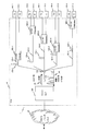
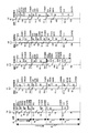
- FIG. 2 is a frame configuration diagram illustrating a configuration example of a downlink signal.
- the downlink signal (hereinafter also referred to as a downlink frame or simply a frame) has a 125 ⁇ s period structure defined in ITU-T Recommendation G984.3, and has a frame synchronization pattern 20, PLOAM (Physical Layer Operation, Admission). and Maintenance) 21, grant instruction 22, and frame payload 23.
- the frame synchronization pattern 20 is a fixed pattern for each ONU 300 to identify the head of a frame having a period of 125 ⁇ sec.
- the PLOAM 21 stores information used by the OLT 200 for managing the physical layer of each ONU 300.
- the frame payload 23 stores a user signal from the OLT 200 to each ONU 300.
- the grant instruction 22 indicates the upstream signal transmission timing (grant) of each ONU 300. More specifically, the grant instruction 22 indicates a grant for each TCONT that is a user signal control unit within each ONU 300.
- Each TCONT signal is composed of a TCONT ID 27 for identifying the TCONT, a Strat 28 indicating the signal transmission start timing, an End 29 indicating the transmission end timing, and a transmission rate designation area 30.
- the transmission rate designation area 30 is a signal introduced by the PON of the present invention, and indicates whether to use a 1 Gbit / second signal or a 10 Gbit / second signal for the upstream signal. Note that Start 28 and End 29 indicate the transmission start timing and the transmission end timing for the above two speed signals.
- the time unit is specified by the number of bytes at the signal speed of 1 Gbit / second, and 10 Gbit / second.
- the unit of time of the second signal is shown in units of 8 bytes. This means that the speed of a 10 Gbit / second signal is eight times that of a 1 Gbit / second signal, and if specified in this way, both a 1 Gbit / second signal and a 10 Gbit / second signal can be operated with one notation. It is to become.
- the OLT 200 periodically transmits a message permitting transmission of uplink data including the grant instruction 22 to each ONU 300, and instructs each TCONT how much uplink communication band should be used.
- the Start 28 and End 29 are information indicating at what timing data transmission should be started and ended in each cycle in which the OLT 200 transmits a grant instruction.
- the ONU 300 transmits an uplink signal at the transmission rate designated in the transmission rate designation area 30.
- the data length of the data to be transmitted may be specified, and an instruction may be given to transmit the data for the specified data length from the timing of Start 28.
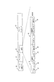
- FIG. 3 is a signal configuration diagram illustrating a configuration example of the uplink signal.
- An upstream signal (hereinafter also referred to as a GEM packet or simply a packet) includes a fixed-length burst overhead 36 consisting of a preamble 30 and a delimiter 31, a control signal consisting of a PLOAM 31 and a queue length 33, and a 5-byte GEM.
- This is a variable-length packet composed of a header 34 and burst data 37 composed of a variable-length GEM payload 35.
- the above-described Start 28 indicates the start position of the PLOAM 32, that is, the start position of the burst data 37, and the End value 29 indicates the end position of the GEM payload 35 (burst data 27).
- the guard time 38 is a no-signal section from the end position of the GEM payload 34 to the start position of the preamble 30 of the next packet, and prevents collision and interference of packets transmitted from each ONU 300 on the backbone optical fiber 17-1. Therefore, a no-signal section having a length defined in ITU-T recommendation G984.3 is taken. Therefore, since the guard time 38, the preamble area 30 and the delimiter area 31 are interposed between the burst data 37 transmitted from each ONU 300 (or TCONT), the End 29 of the previous burst data 37 and the next burst data 37 An interval of several bytes occurs between the Strat 28 and the Strat 28.
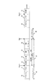
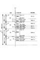
- FIG. 4 is a sequence diagram showing an example of PON operation, and shows the relationship between the DBA operation and period and the grant operation and period based on the result of the DBA.
- the OLT 200 transmits a transmission permission message 40 including the grant instruction 22 to each of the ONUs 300-1 to 10-3 every grant period 44 to 48 of 125 ⁇ s.
- the transmission permission message 40 also includes information (Request report) for requesting a report of the amount of data waiting for transmission accumulated in the transmission queue provided in the TCONT of each ONU.
- Each ONU 300 transmits data accumulated in the transmission queue in the time slot specified by the Start 28 and End 29 of the grant instruction 22 and transmits using the queue length 33 included in the upstream message 41 (packet shown in FIG. 3).
- the waiting data amount is reported to the OLT 200 (Report).
- the OLT 200 performs DBAs 42 and 43 for determining how much data amount is allowed to be transmitted to each ONU (TCONT) based on a report (amount of transmission waiting data) received from each ONU 300 in a predetermined DBA cycle 49. . Specifically, based on the amount of data waiting for transmission and the contract with each user, the amount of data permitted to be transmitted to each TCONT in the next transmission is determined. Since this DBA does not need to be executed every grant period 45 to 48 of 125 ⁇ s, the DBA is configured so as to collect a plurality of grant periods. In this embodiment, the DBA is performed once every 4 grant periods (0.5 msec).
- the OLT 200 Since the amount of data permitted to be transmitted to all TCONTs in one DBA 42 is determined, the OLT 200 causes each grant so that all TCONTs transmit the determined data amount in any one of the grant periods 45 to 48. TCONT that transmits data in a cycle and its data transmission Start 28 and End 29 are determined. The Start 28 and End 29 are transmitted to each ONU 300-1 to 10-3 by the transmission permission message 40 including the grant instruction 22 (Grant), and each ONU 300-1 to 10-3 has a timing according to the grant. The data is transmitted to the OLT 200.
- the PON with a DBA cycle of 0.5 ms and a grant cycle of 125 ⁇ s will be described. However, the DBA cycle and the grant cycle may be set to other values.
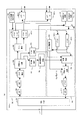
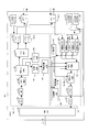
- FIG. 5 is a block configuration diagram showing a configuration example of an ONU used in the PON of the present invention.
- the ONU 300 includes a WDM filter 501, a reception unit 540, a transmission unit 541, and a user interface (IF) 508.
- the reception unit 540 includes an O / E conversion unit 502, an AGC 503, a clock extraction unit 504, a PON frame separation unit 505, a frame distribution unit 506, a packet buffer 507, a grant termination unit 520, a PLOAM termination unit 521, and an equivalent delay value storage unit 522.
- the transmission unit 541 includes a packet buffer 509, a transmission control unit 510, a PON frame generation unit 511, a driver 512, an E / O unit 513, and a queue length monitoring unit 530.
- the operation clock of the reception unit 540 is supplied by the downlink 10G clock generation unit 542.
- the operation clock of the transmission unit 541 is supplied by selecting the output of either the uplink 10G clock generation unit 543 or the uplink 1G clock generation unit 544 by the selector 545. This selector control is determined by a transmission rate instruction (30 in FIG. 2) from the OLT 200 read by the grant terminal unit 520.
- the optical signal received from the branch optical fiber 120 is wavelength-separated by the WDM filter 501 and then converted into an electrical signal by the O / E converter 502.
- the clock extraction unit 504 performs retiming
- the PON frame separation unit 505 performs signal separation described in FIG. Specifically, the signal in the PLOAM area 1902 is sent to the PLOAM termination unit 521, the signal in the grant indication area 1903 is sent to the grant termination part 520, and the signal in the frame payload area 1904 is sent to the frame distribution unit 506.
- the user signal output from the frame distribution unit 505 is temporarily stored in the packet buffer 507-1 and the packet buffer 507-2, and then output through the user IF 508-1 and the user IF 508-2, respectively.
- the signals input from the user IF 508-1 and the user IF 508-2 are temporarily stored in the packet buffer 509-1 and the packet buffer 509-2, respectively, and then read under the control of the transmission control unit 510. And is assembled into a packet (see the format of FIG. 3) by the PON frame generation unit 511.
- the queue length monitoring unit 530 monitors the usage amount of the packet buffer 509.
- the buffer usage information is stored in the packet queue length 33 and transmitted to the OLT, and the OLT 200 controls the grant amount to be issued by performing DBA based on this information.
- the signal assembled by the PON frame generation unit 511 is converted into current by the driver 512, converted into an optical signal by the E / O unit 513, and transmitted to the branch optical fiber 120 through the WDM filter 501.
- the transmission control unit 510 performs control to transmit a signal toward the OLT based on the grant value extracted from the grant termination unit 520.
- the distance difference is corrected by the ranging specified in the ITU-T recommendation G984.3.
- a transmission timing correction value called an equalization delay value is stored in the PLOAM 21 shown in FIG. 2 and transmitted to each ONU 300.
- the ONU 300 accumulates the equalization delay value received via the PLOAM termination unit 321 in the equalization delay value storage unit 522, and the transmission control unit 510 adjusts the transmission timing of the signal based on the equalization delay value, thereby determining the distance. Correction is performed so that signals from the ONUs 300-1 to 300-n do not collide with each other on the backbone optical fiber 110.
- each functional block of the ONU 300 described above is realized by firmware stored in a CPU or memory, or realized by electrical components such as an electrical / optical conversion circuit, a memory, and an amplifier. Further, these functions may be realized by dedicated hardware (LSI or the like) specialized for each processing. Furthermore, the configuration of the ONU 300 is not limited to the above description, and various functions may be mounted as necessary.
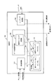
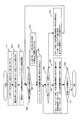
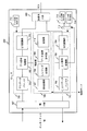
- FIG. 6 is a block diagram showing a configuration example of the OLT used in the PON of the present invention.
- the OLT 200 includes a network IF unit 607, a control unit 700, a transmission unit 710, a reception unit 711, and an optical signal IF unit 606.
- the transmission unit 710 includes a downlink data buffer 701, a downlink signal processing unit 702, and an E / O conversion unit 703.
- the reception unit 711 includes an O / E conversion unit 704, an upstream signal processing unit 705, and an upstream data buffer 706.
- the operation clock of the transmission unit 710 is supplied by the downlink 10G clock generation unit 712.
- the operation clock of the reception unit 711 is supplied by selecting the output of either the uplink 10G clock generation unit 713 or the uplink 1G clock generation unit 714 by the selector 715.
- This selector control is performed by the data transmission permission unit 709. A specific transmission rate determination method will be described in detail later with reference to the drawings.
- the downlink data buffer 701 temporarily stores data received from the upper network 20 via the network IF unit 607.
- the downstream signal processing unit 702 performs processing necessary for relaying the optical signal from the upper network 20 to the ONU 300.
- the E / O conversion unit 703 converts the electrical signal into an optical signal and transmits the optical signal (downstream signal) to the ONU via the optical signal IF unit 606.
- the O / E conversion unit 704 converts the optical signal received from the ONU 300 via the optical signal IF unit 606 into an electrical signal.
- the upstream signal processing unit 705 performs processing necessary for relaying a signal from the ONU 300 to the upper network 20.
- the upstream data buffer 706 temporarily stores data to be transmitted to the higher level network 20 via the network IF unit 607.
- the control unit 700 is connected to each functional block described above, executes various processes necessary for communication (monitoring / control, etc.) with a plurality of ONUs 300, and relays signals between the upper network 20 and the ONUs 300. It has the function to do.
- the DBA processing unit 707 assigns how much communication bandwidth is allocated to each ONU 300 (TCONT) accommodated by the OLT 200 within a predetermined DBA cycle (in this embodiment, 0.5 msec cycle). A dynamic bandwidth allocation process is performed, and it is determined how many bytes are allocated to each ONU 300 (TCONT) within the total number of bytes that can be transmitted in one DBA cycle.
- the ranging processing unit 708 Prior to data transmission / reception between the OLT 200 and the ONU 300, transmits a ranging signal related to distance measurement to each ONU, and measures the time until a response to the signal is received, thereby allowing the OLT 200 and each ONU 300 to perform measurement.
- the ranging processing unit 708 receives a response signal to the ranging signal received via the upstream signal processing unit 705 based on the ranging procedure specified by ITU-T recommendation G984.3.
- the equalization delay value described in 5 is generated and transmitted to each ONU 300 via the downlink signal processing unit 702.
- each ONU 300 transmits the data by adding the transmission delay time notified from the timing (grant) permitted to transmit the data specified by the DBA from the OLT 200.
- the data transmission permission unit 709 transmits a timing Start (FIG. 2: 28) at which each ONU 300 should start data transmission in a certain grant period. And the timing End (FIG. 2: 29) to be terminated are determined for each byte. Also, the speed of the signal that permits transmission to the ONU 300 (in this embodiment, 1 Gbit / second or 10 Gbit / second) is also determined. That is, a grant is instructed.
- the storage unit 710 is a memory that stores information necessary for the processing of the control unit 700.
- the control unit 700 communicates with a control board (for example, a maintenance terminal configured with a PC) provided for the PON, and controls control parameters (for example, ONU subscription conditions, contract traffic, etc.) necessary for control in advance. Or monitoring information (for example, a failure occurrence status or a transmission permission data amount to each ONU) based on a request from a maintenance person.
- a control board for example, a maintenance terminal configured with a PC
- control parameters for example, ONU subscription conditions, contract traffic, etc.
- monitoring information for example, a failure occurrence status or a transmission permission data amount to each ONU
- each functional block of the OLT 200 described above is realized by firmware stored in a CPU or memory, or realized by electrical components such as an electrical / optical conversion circuit, memory, and amplifier. Further, these functions may be realized by dedicated hardware (LSI or the like) specialized for each processing. Furthermore, the configuration of the ONU 300 is not limited to the above description, and various functions may be mounted as necessary.
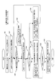
- FIG. 7 is an explanatory diagram illustrating a configuration and an operation example of a control unit provided in the OLT.
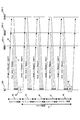
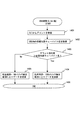
- FIG. 8 and FIG. 9 are operation flowcharts showing an operation example of the control unit of the OLT.
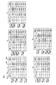
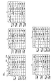
- FIG. 10 is a memory configuration diagram illustrating a configuration example of an allocated byte length table that stores a bandwidth (number of bytes) allocated to each ONU generated by the control unit, and
- FIG. 11 illustrates each ONU generated by the control unit. It is a memory block diagram which shows the structural example of the transmission timing table which memorize
- the DBA processing unit 707 receives the queue length, which is the amount of data waiting for transmission of each ONU 300 within the DBA cycle, from the upstream signal (FIG. 3:33) (FIG. 8: 1101). In the DBA processing unit 707, parameters related to the amount of data permitted to the ONU are set from the control board (see FIG.
- FIG. 10 shows a configuration example of the allocated byte length table 802, which includes an ONU-ID 901 that is an ONU identifier and a byte length 902 that is allocated to the ONU by the DBA.
- the allocation byte length to each ONU is changed in five ways (a) to (e) based on the queue length from each ONU. Specifically, the queue length from each ONU increases corresponding to (a) to (e), and the number of bytes allocated to each ONU and the total number of allocated bytes in the DBA cycle increase. As shown.
- band allocation and the like are performed in units of TCONT. However, in this embodiment, it is assumed that each ONU has one TCONT, and therefore, TCONT-ID and ONU- Since the ID is the same, ONU-ID is displayed.
- the transmission timing determination unit 801 provided in the data transmission permission unit 709 reads the contents of the allocated byte length table 802 (FIG. 7: (2)), and the time slot corresponding to the byte length 902 allocated to each ONU. Is assigned for each grant period, and a transmission timing table 803 in which the ONU-ID is associated with the byte length assigned within each grant period is created and stored in the storage unit 710 (FIG. 7: (3)). Specifically, the following control is performed to determine the ONU transmission timing and transmission speed.
- the number of bytes that can be transmitted in the DBA cycle is 1.24416 Gbit / sec.
- X 125 ⁇ sec x 2 cycles / 8 + 9.95328 Gbit / sec x 125 ⁇ sec x 2 cycles / 8 349,920 bytes
- the data transmission permission unit 709 determines the transmission rate based on the total of the allocated byte lengths obtained from the allocated byte length table 802 as follows, and sets the transmission rate value in each grant period of the transmission timing table 803. Enter.
- (A) It is determined whether or not the sum of the allocated byte lengths ⁇ 77216 (FIG. 8: 1103), and in the case of Yes, the total grant period is determined at a speed of 1 Gbit / sec (FIG. 8: 1104).
- (B) It is determined whether or not 77216 ⁇ sum of allotted byte lengths ⁇ 213456 (FIG. 8: 1105).
- the first to third grant periods are determined at a speed of 1 Gbit / second, and the fourth grant period Is determined at a speed of 10 Gbit / sec (FIG. 8: 1106).
- C It is determined whether or not 211456 ⁇ the total sum of allocated byte lengths ⁇ 349536 (FIG. 8: 1107). If Yes, the first to second grant periods are determined to a speed of 1 Gbit / sec, and the third to the third The 4-grant period is determined at a speed of 10 Gbit / sec (FIG. 8: 1108).
- D It is determined whether or not 349536 ⁇ sum of allotted byte lengths ⁇ 485616 (FIG. 8: 1109).
- the first grant period is determined to be 1 Gbit / sec, and the second to fourth grant periods are determined. Is determined at a speed of 10 Gbit / sec (FIG. 8: 1110). In the case of No, the entire grant period is determined to be a speed of 10 Gbit / sec (FIG. 8: 1111).
- the data transmission permission unit 709 refers to the byte length (FIG. 10: 902) stored in the allocated byte length table 802 and within each grant period for each ONU. The time slot for transmitting data is determined, and the value of the transmission timing table 803 is generated (FIG. 8: 1112 (detailed operation example will be described later)).
- the number of allocated bytes in the allocated byte length table is divided by 8.
- the time units of Start 28 and End 29 are specified in bytes at a signal speed of 1 Gbit / sec. This is because the unit is defined to be expressed in units of 8 bytes.
- FIG. 9 is also an operation flowchart showing an operation example of the control unit of the OLT, and is an operation flow diagram showing a detailed operation example of the transmission timing determining step (FIG. 8: 1112).
- the transmission timing of the upstream signal of each ONU is determined as follows. (E1) The allocated byte length of the first ONU-ID is read from the allocated byte length table 802 (1301). Band allocation is possible even if the youngest ONU-ID (usually 1) is taken each time as the first ONU-ID, but in this embodiment, a value shifted by 1 for each DBA cycle (1 ⁇ 2 ⁇ 3 ⁇ ...) is used. The reason for this is that in the embodiment described with reference to FIG.
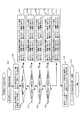
- FIG. 11 shows a configuration example of the transmission timing table 803.
- An ONUT-ID 901 that is an ONU identifier, a Start area 1002 that stores a data transmission start timing Start 28 within a certain grant period, and an End that stores a data transmission end timing End29.
- An area 1003 and a speed area 1004 for storing a signal transmission speed are used.
- (A) to (e) in the figure correspond to the allocated byte tables (a) to (e) shown in FIG. 10, respectively, and the control described with reference to the flowcharts of FIGS. 8 and 9
- the signal transmission rate in each grant period is changed according to the total number of assigned bytes, and the assignment of the transmission timing (bandwidth) of the signal is changed accordingly.
- the transmission timing determination unit 801 transmits a transmission permission message including the grant instruction 22 (US Bandwidth MAP) to each ONU 300 according to the contents of the transmission timing table 803 to notify the transmission timing of data (FIG. 8: 1113). .
- Each ONU 300 that has received the grant instruction transmits an uplink signal at the transmission timing and transmission speed instructed from the OLT 200 by the configuration and operation described above with reference to FIG.
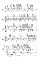
- FIG. 12 is an operation explanatory diagram showing how an upstream signal from each ONU is received by the OLT.
- Signals from each ONU are optically time-division multiplexed on the backbone optical fiber 110 in the order of the transmission timing table 803. This shows the state of arriving at the OLT.
- (A) to (e) in the figure correspond to (a) to (e) in FIGS. 10 and 11 according to the total number of allocated bytes.
- the signal transmission speed in each grant period is changed, and the assignment of signal transmission timing (bandwidth) according to the change is shown.
- the total allocated byte lengths are different (a) to (e
- the time slots from the first grant period to the fourth grant period are used as much as possible to reduce power consumption and improve transmission efficiency.
- the value (1 ⁇ 2 ⁇ 3 ⁇ ...) Shifted by one for each DBA cycle is used as the first ONU-ID, the byte length allocation of (a) to (e) in FIG. Even if it occurs, as shown in FIGS. 12A to 12E, the 1 Gbit / s speed with less power consumption is assigned to all ONUs in order, and the power consumption increases only for a specific ONU. Can be avoided.
- FIG. 13 is an operation flow diagram showing another operation example of the control unit provided in the OLT, and is an operation flow diagram showing another implementation example of the transmission timing determination step (FIG. 8: 1112 and FIG. 9).
- the difference from the flowchart shown in FIG. 9 is that an operation (1311) for rearranging the rows of the allocated byte length table 802 in the ascending order of the byte length is added.
- FIG. 14 is a memory configuration diagram showing a configuration example of the allocated byte length table rearranged in step 1311, which is arranged in ascending order of the allocated byte count.
- the allocated bandwidth is the smallest. Searching and selecting ONU-ID from the allocated byte length table and assigning transmission timing, and then searching and selecting ONU-ID having a small allocated bandwidth from the allocated byte length table and assigning transmission timing. Must be repeated.
- the allocated byte length table 802 ′ in the order of decreasing allocated bytes shown in FIG.
- transmission timings can be allocated in order starting from the ONU-ID located at the top of the table. Therefore, there is an advantage that the search procedure is summarized and the transmission timing allocation operation is made efficient.
- the transmission timing table 803 ′ shown in FIG. 15 is generated.
- the OLT 200 receives signals in the state shown in FIG.
- one DBA cycle is configured by four grant cycles and the transmission rate is switched for each grant cycle.
- one DBA cycle is configured by more grant cycles and transmitted.
- the ONU determines by itself the transmission rate used for uplink communication.
- a buffer memory for temporarily storing uplink communication contents in the ONU is provided corresponding to a plurality of priorities, and the data amount of the buffer memory with a high priority is set at the timing indicated by the transmission timing control unit.
- the rate of 1 Gbit / sec is used if the rate is lower than the rate that can be transmitted at a rate of 1 Gbit / s
- the rate of 10 Gbit / s is used if the rate that is higher than the rate that can be transmitted at 1 Gbit / s It is a configuration that operates by determining the speed. The detailed configuration and operation will be described below with reference to the drawings.
- FIG. 17 is a block diagram showing another example of the ONU used in the PON of the present invention.
- FIG. 18 is also a block diagram showing another example of the OLT.
- Each ONU determines the transmission rate of the upstream signal. It is the block block diagram which showed the structural example corresponding to the operation
- the ONU 300 ′ includes a transmission rate determination unit 546, and differs from the ONU 300 described above in that the upstream transmission rate is determined based on the outputs of the grant termination unit 520 and the queue length monitoring unit 530 and the selector 545 is controlled.
- the buffer 509 that temporarily stores the upstream signal is configured to store the signal by dividing the buffer into a high priority buffer and a low priority buffer divided according to the signal priority.
- the OLT 200 ′ is different from the OLT 200 described above in that the upstream signal processing unit 705 controls the selector 715 that selects a transmission rate based on the result of receiving the upstream signal. That is, since an upstream transmission rate signal determined by the ONU 300 ′ is received, the upstream signal processing unit 705 analyzes the waveform to determine the upstream transmission rate.
- the first information of the uplink signal is a preamble (30 in FIG. 3), and a predetermined value is used for this preamble, and 10 alternating bit strings that are particularly convenient for high-speed clock extraction are used. There are many cases.
- one pulse width is about 803 picoseconds. Further, when the transmission rate of the uplink signal is 10 Gbit / second, one pulse width is about 100 picoseconds. Therefore, the uplink signal processing unit 705 can easily know the transmission rate by measuring the width of the preamble pulse of the received uplink signal.
- FIG. 19 is an operation flowchart showing an example of the operation of the ONU transmission rate determination unit 546, which operates as follows to determine the uplink signal transmission rate.
- a grant instruction (FIG. 2:22) is received from the OLT 200 ′ within the DBA period (1401)
- the queue length monitoring unit 530 uses the queue lengths of the high priority buffers 509-1 and 509-3 in the upstream buffer 509. Is transmitted to the transmission rate determination unit 546 (1402).
- the amount of data remaining in the high-priority buffers 509-1 and 509-3 is less than the amount that can be transmitted at a speed of 1 Gbit / second compared to the timing (ground instruction length) indicated by the transmission control unit 510.
- the rate is 1 Gbit / sec (1405) (if No in 1403) and exceed the amount that can be transmitted at 1 Gbit / sec (if 1403 is Yes), then the rate is 10 Gbit / sec. (1404) is used, and the transmission control unit 510 and the selector 545 are controlled by the determination result.
- FIG. 20 is a diagram for explaining an operation example of the ONU.
- an uplink signal transmission control table provided in a memory (not shown) in the transmission control unit 510 in the ONU 300 ′.
- It is the memory block diagram which showed the example of a structure. This memory may be in a functional block other than the transmission control unit 510.
- the memory provided for each ONU is displayed for all the ONUs for convenience of explanation, and each ONU only needs to have data of its own ONU.
- the information of the row corresponding to the ONU-ID in the figure is used for the determination operation of the transmission rate determination unit 546.
- the permitted byte value 1005 is 375 bytes, but since the data amount 1006 held in the high priority queue is 200 bytes, 200 bytes of data in the high priority queue is 1 Gbit / second. And 175 bytes of the data held in the low priority queue are transmitted at 1 Gbit / sec.
- FIG. 21 is an operation explanatory diagram showing another example of the uplink signal reception operation in the OLT.
- each ONU has the information shown in FIG. 20, each ONU time-division multiplexed on the backbone optical fiber 110 is shown. It shows a state in which the OLT receives an upstream signal from.
- each ONU does not transmit all data waiting for transmission, but transmits only high priority data using a low transmission speed. Thus, it becomes possible to perform selection of uplink signal transmission.
- the current PON transmission standard defined in ITU-T recommendation G984.3 does not stipulate a mechanism that separates the queue length of high priority data and transmits it to the OLT. Although it is not possible to determine the transmission rate in consideration of the priorities, it is possible with this embodiment. In addition, it is possible for each ONU to select as a unique judgment that importance is placed on the power consumption saving requirement.
Abstract
Provided is a passive optical network system for operating a mixture of PONs with differing transmission speeds and is capable of reducing power consumption on the basis of the amount of signals being transmitted. The master station of the passive optical network system, which determines the amount and timing of signals sent thereto by each of a plurality of slave stations on the basis of the requests of the plurality of slave stations and receives signals from the plurality of slave stations via an optical fiber network, is equipped with a control unit that determines in each set cycle the amount, transmission timing, and transmission speed of the signals that each slave station is permitted to transmit to said master station on the basis of the amount of signals that each of the plurality of slave stations has requested to transmit, and that notifies such to each slave station. Additionally, each of the plurality of slave stations is equipped with a control unit that transmits signals to the master station at a first transmission speed or a second transmission speed that is faster than the first transmission speed, and is configured to transmit signals with either the first transmission speed or the second transmission speed on the basis of notifications from the master station.
Description
本発明は、受動光網システム、光多重終端装置及び光網終端装置に係り、特に、複数の加入者接続装置が光伝送回線を共有する受動光網システムに関する。
The present invention relates to a passive optical network system, an optical multiple termination device, and an optical network termination device, and more particularly to a passive optical network system in which a plurality of subscriber connection devices share an optical transmission line.
通信網の高速・広帯域化が加入者を接続するアクセス網でも進められ、国際電気通信連合(以下ITU-Tと称す)の勧告G984.3等で規定された受動網光システム(Passive Optical Network system:以下PONと称する)の導入が図られている。PONは、上位の通信網と接続される光多重終端装置(Optical Line Terminator:以下OLTと称する)と、複数の加入者の端末(PCや電話)を収容する光網終端装置(Optical Network Unit:以下ONUと称する)とを、基幹光ファイバと光スプリッタと複数の支線光ファイバとを含む光受動網で接続したシステムである。具体的には、各ONUに接続された端末(PC他)からの信号を光信号で支線光ファイバから光スプリッタを介して基幹光ファイバで光学(時分割)多重してOLTに送り、OLTが各ONUからの信号を通信処理して上位の通信網に送信する、あるいは、OLTに接続される他のONUに送信するという形態で通信を行うものである。
High-speed and broadband communication networks are also being promoted in access networks that connect subscribers. Passive optical network systems (Passive Optical Network systems) defined by the International Telecommunications Union (hereinafter referred to as ITU-T) Recommendation G984.3, etc. : Hereinafter referred to as PON). PON is an optical multiple terminator (hereinafter referred to as OLT) connected to a higher-level communication network and an optical network terminator (Optical Network Unit) that accommodates a plurality of subscriber terminals (PCs and telephones). (Hereinafter referred to as ONU) is connected by an optical passive network including a backbone optical fiber, an optical splitter, and a plurality of branch optical fibers. Specifically, signals from terminals (PCs, etc.) connected to each ONU are optically (time-division-multiplexed) from the branch optical fiber via the optical splitter via the optical fiber splitter (time division) and sent to the OLT. Communication is performed in a form in which signals from each ONU are processed and transmitted to a higher-level communication network, or transmitted to other ONUs connected to the OLT.
PONの導入は64kbit/秒のような低速信号を扱うシステムから始まり、固定長のATMセルを最大約600Mbit/秒で送受信するBPON(Broadband PON)あるいはイーサネット(登録商標。以下では登録商標の表記を省略)の可変長パケットを最大約1Gbit/秒で送受信するイーサネットPON(EPON)や、より高速な2.4Gbit/秒程度の信号を扱うGPON(Gigabit capable PON)の導入が進められている。更に、今後は10Gbit/秒から40Gbit/秒の信号を扱うことが可能な高速PONの実現が求められている。そして、これらの高速PONを実現する手段としては、現状のPONと同様な複数の信号を時分割多重するTDM(Time Division Multiplexing)を利用することが検討されている。尚、現状のTDMを用いたPONは、上り(ONUからOLT)の信号と下り(OLTからONU)の信号とで異なる波長を用い、OLTと各ONU間の通信は、各ONUに対して通信時間を割当てる構成である。具体的には、多様な信号(音声、画像、データ等)を扱い易いバースト状の可変長信号(バースト信号)を割当てる構成である。
The introduction of PON begins with a system that handles low-speed signals such as 64 kbit / sec. BPON (Broadband PON) or Ethernet (registered trademark) that transmits and receives fixed-length ATM cells at a maximum of approximately 600 Mbit / sec. The introduction of Ethernet PON (EPON) that transmits / receives variable length packets at a maximum of about 1 Gbit / sec and GPON (Gigabit capable PON) that handles higher-speed signals of about 2.4 Gbit / sec is underway. Furthermore, in the future, it is required to realize a high-speed PON capable of handling signals of 10 Gbit / second to 40 Gbit / second. As means for realizing these high-speed PONs, use of TDM (Time Division Multiplexing) in which a plurality of signals similar to the current PON are time-division multiplexed is being studied. Note that the current PON using TDM uses different wavelengths for upstream (ONU to OLT) signals and downstream (OLT to ONU) signals, and communication between the OLT and each ONU is communicated to each ONU. It is the structure which allocates time. Specifically, it is a configuration in which a burst-like variable length signal (burst signal) that can easily handle various signals (sound, image, data, etc.) is assigned.
上記各PONでは、様々な場所に点在する加入者宅にONUを設置するため、OLTから各ONUまでの距離が異なる。即ち、OLTから各ONU迄の基幹光ファイバと支線光ファイバからなる光ファイバの長さ(伝送距離)がばらつくため、各ONUとOLT間の伝送遅延(遅延量)がばらつき、各ONUが異なるタイミングで信号を送信しても基幹光ファイバ上で各ONUからの光信号同士が衝突・干渉する可能性がある。このため、各PONでは、例えばITU-Tの勧告G984.3で規定したレンジング技術を用いて、OLTとONUとの間の距離測定を実施後に各ONUからの信号出力が衝突しないように各ONUの出力信号の遅延を調整する。また、OLTは、動的帯域割当て(Dynamic Bandwidth Assignment:以下DBAと称する)技術を用いて各ONUからの送信要求に基づき該ONUに送信を許可する信号の帯域を決めると、レンジングで測定した遅延量も考慮した上で、各ONUからの光信号が基幹光ファイバ上で衝突・干渉しないように各ONUへ送信タイミングを指定する。すなわち、PONは、OLTと各ONU間で送受信される信号のタイミングがシステム内で管理された状態で通信の運用がなされるように構成されている。
In each of the above PONs, ONUs are installed in subscriber homes scattered in various places, and therefore the distance from the OLT to each ONU is different. That is, since the length (transmission distance) of the optical fiber composed of the backbone optical fiber and the branch optical fiber from the OLT to each ONU varies, the transmission delay (delay amount) between each ONU and the OLT varies, and each ONU has a different timing. Even if the signal is transmitted by the optical signal, the optical signals from the ONUs may collide and interfere with each other on the backbone optical fiber. For this reason, in each PON, for example, the distance measurement between the OLT and the ONU is performed using the ranging technique defined in ITU-T recommendation G984.3 so that the signal output from each ONU does not collide after the distance measurement is performed. Adjust the output signal delay. In addition, the OLT uses a dynamic bandwidth assignment (hereinafter referred to as DBA) technology to determine the bandwidth of a signal that is permitted to be transmitted to each ONU based on a transmission request from each ONU. In consideration of the amount, the transmission timing is designated to each ONU so that the optical signal from each ONU does not collide or interfere on the backbone optical fiber. That is, the PON is configured such that communication is performed in a state where the timing of signals transmitted and received between the OLT and each ONU is managed in the system.
上記GPONでは、OLTで基幹光ファイバ上に多重された各ONUからの信号を識別して処理できるように、各ONUからの送信信号は、最大12バイトからなる干渉防止用のガードタイムと、OLT内受信器の信号識別閾値の決定およびクロック抽出に利用するプリアンブルならびに受信信号の区切りを識別するデリミタと呼ばれるバーストオーバヘッドバイトと、PONの制御信号(オーバヘッドあるいはヘッダと称することもある)とがデータ(ペイロードと称することもある)の先頭に付加される構成である。尚、各データは、可変長のバーストデータであり、各データの先頭に可変長データを処理するためのGEM(G-PON Encapsulation Method)ヘッダと呼ばれるヘッダが付加される。
In the GPON, the transmission signal from each ONU is transmitted with a guard time for interference prevention consisting of a maximum of 12 bytes and an OLT so that signals from each ONU multiplexed on the backbone optical fiber can be identified and processed by the OLT. A burst overhead byte called a delimiter for identifying a preamble and a received signal delimiter used for determination of a signal identification threshold of an internal receiver and clock extraction, and a control signal (sometimes called overhead or header) of PON are data ( (It may be called a payload). Each data is variable-length burst data, and a header called a GEM (G-PON Encapsulation Method) header for processing the variable-length data is added to the head of each data.
一方、各ONUがOLTからの信号を識別して処理できるように、OLTから各ONUに向けて送信される信号の先頭に、先頭を識別するためのフレーム同期パタンと、監視・保守・制御情報を送信するPLOAM領域と、各ONUの信号送信タイミングを指示するグラント指示領域と呼ばれるオーバヘッド(ヘッダと称されることもある)とが各ONU宛に時分割多重化されたデータに付加される構成である。なお、多重化される各ONU宛のデータには、ONUからの信号と同様に、可変長データを処理するためのGEMヘッダが付加されている。OLTは、グラント指示領域を用いて各ONUの上り送信許可タイミング(送信開始(Start)と終了(Stop))を各ONUにバイト単位で指定する。この送信許可タイミングをグラントと称している。そして、各ONUが該許可タイミングでOLT宛のデータを送信すると、これらが光ファイバー上で光学(時分割)多重されOLTで受信される。
On the other hand, at the head of the signal transmitted from the OLT to each ONU, a frame synchronization pattern for identifying the head, and monitoring / maintenance / control information so that each ONU can identify and process the signal from the OLT A PLOAM area for transmitting a signal and an overhead (sometimes referred to as a header) called a grant instruction area for instructing signal transmission timing of each ONU are added to data time-division multiplexed to each ONU It is. Note that a GEM header for processing variable length data is added to the data addressed to each ONU to be multiplexed, similarly to the signal from the ONU. The OLT specifies the upstream transmission permission timing (transmission start (Start) and end (Stop)) of each ONU in units of bytes using the grant indication area. This transmission permission timing is called a grant. When each ONU transmits data addressed to the OLT at the permission timing, these are optically (time-division) multiplexed on the optical fiber and received by the OLT.
PONは、BPONからGPONへの移行のように、より高速信号を処理するものへと開発・導入が進んできている。PONの信号伝送機能を実現する光モジュールやLSIは、伝送速度が速いほど大量の電力を消費することが知られている。例えば、光モジュールはより高い伝送速度を達成するために、伝送速度が高いほど大量の電流を流すことで必要な帯域を確保している。また、CMOS技術を用いたディジタル信号処理LSIは、動作クロックの速度の2乗にほぼ比例した電力を消費する。すなわち、今後も伝送速度が速くなるほど大量の消費電力が消費される傾向にある。
PON has been developed and introduced to process higher-speed signals, such as the transition from BPON to GPON. It is known that optical modules and LSIs that realize the PON signal transmission function consume a large amount of power as the transmission speed increases. For example, in order to achieve a higher transmission speed, the optical module secures a necessary band by flowing a larger amount of current as the transmission speed is higher. In addition, a digital signal processing LSI using CMOS technology consumes power approximately proportional to the square of the speed of the operation clock. That is, a larger amount of power consumption tends to be consumed as the transmission speed increases.
一方、PONの加入者は、より高速なPONを求める傾向があるが常時速い伝送速度を欲しているわけではない。通信を行っていない時間帯には当然速い伝送速度を要求しないことはもちろん、通信中でも特にインターネットアクセスにおけるデータ伝送においては、大量の画像データや大容量ファイルをダウンロードやアップロードする期間に速い伝送速度を要求するが、内容の閲覧中や作業中は速い伝送速度を必要としない。また、データ伝送に用いられるTCPプロトコルでは、一定数のパケットを受信すると確認信号パケットを返送することが必要で、データの送信側は確認信号パケットを受信する迄後続のデータを送信しない。すなわち、データ伝送中であってもデータトラヒックは極めてバースト性の高い伝送形態となることが多くなるのが運用の実態である。しかし、現実のPONを構成する光モジュールやLSIは実質的にデータを伝送しない時間帯も動作して電力を消費しており、著しい電力の無駄を生じる原因となっている。このため、エンドユーザトラヒックが小さい時は低速の伝送速度で伝送を行い、エンドユーザトラヒックが大きい時は高速の伝送速度で伝送を行うことの可能なPONシステムが求められることになる。
On the other hand, PON subscribers tend to seek faster PONs, but they do not always want fast transmission speeds. Needless to say, a high transmission rate is not required during non-communication periods, and of course during data transmission, especially during Internet access, a high transmission rate is required during the period of downloading and uploading large amounts of image data and large files. Requests, but does not require high transmission speed while browsing or working with content. Further, in the TCP protocol used for data transmission, it is necessary to return a confirmation signal packet when a certain number of packets are received, and the data transmission side does not transmit subsequent data until the confirmation signal packet is received. In other words, even in the course of data transmission, the actual state of operation is that data traffic often has a transmission form with extremely high burstiness. However, optical modules and LSIs constituting an actual PON operate and consume power in a time zone in which data is not substantially transmitted, causing a significant waste of power. For this reason, there is a need for a PON system that can perform transmission at a low transmission rate when end-user traffic is small and can perform transmission at a high transmission rate when end-user traffic is large.
本発明は以上の点に鑑み、伝送速度の異なる複数の仕様(規格)のPONを混在させて運用出来る構成のPONにおいて、エンドユーザトラヒックに基づいて消費電力の無駄を極力減らすことの可能な受動光網システムを実現することを目的とする。
In view of the above, the present invention is a passive PON that can reduce the waste of power consumption as much as possible based on end-user traffic in a PON having a configuration in which a plurality of PONs of different specifications (standards) having different transmission speeds can be mixed and operated. The purpose is to realize an optical network system.
上記課題を解決するために、本発明の受動光網システムは、親局と複数の子局とが光スプリッタおよび複数の光ファイバから成る光ファイバ網で接続され、複数の子局の要求に基づき親局が複数の子局の夫々から親局に送信する信号の量とタイミングとを決めて複数の子局からの信号を光ファイバ網を介して受信する受動光網システムの親局に、複数の子局の夫々が送信を要求する信号の量に基づき、子局の夫々に該親局への信号送信を許可する信号の量と送信タイミングと伝送速度を一定周期毎に決めて子局の夫々に通知する制御部を備え、さらに複数の子局の夫々は、第1の伝送速度、もしくは、第1の伝送速度より高速な第2の伝送速度で親局へ信号を送信する制御部を備え、親局からの通知に基づき第1の伝送速度もしくは第2の伝送速度のいずれかで信号を送信する構成とした。
In order to solve the above-described problems, a passive optical network system according to the present invention includes a master station and a plurality of slave stations connected by an optical fiber network including an optical splitter and a plurality of optical fibers, and based on requests from the plurality of slave stations. The master station determines the amount and timing of the signal transmitted from each of the slave stations to the master station, and receives the signals from the slave stations via the optical fiber network. Based on the amount of signals that each of the slave stations requests to transmit, the amount of signals that allow each of the slave stations to transmit signals to the master station, the transmission timing, and the transmission speed are determined for each fixed period. Each of the plurality of slave stations includes a control unit that transmits a signal to the master station at a first transmission rate or a second transmission rate that is faster than the first transmission rate. Prepared, based on the notification from the master station, the first transmission rate or the second transmission rate And configured to transmit a signal in one of transmission rate.
そして、親局の制御部は、複数の子局の夫々が要求した信号の量に基づき任意の子局への送信許可する信号の量を決定すると、この送信許可した信号の量が第1の伝送速度で伝送可能な最大伝送量を下回る場合、子局の信号の伝送速度を第1の伝送速度とし、送信許可した信号の量が第1の伝送速度で伝送可能な最大伝送量を上回る場合は、子局の信号の伝送速度を第2の伝送速度と決定するように構成した。
Then, when the control unit of the master station determines the amount of the signal permitted to transmit to any slave station based on the amount of the signal requested by each of the plurality of slave stations, the amount of the signal permitted to transmit is determined as the first amount. When the transmission rate is less than the maximum transmission amount that can be transmitted, the transmission rate of the slave station signal is the first transmission rate, and the amount of signals permitted to transmit exceeds the maximum transmission amount that can be transmitted at the first transmission rate. Is configured to determine the signal transmission rate of the slave station as the second transmission rate.
尚、伝送速度の決定を親局で行わず、複数の子局の夫々が、送信を要求する信号の量と送信許可された信号の量を比較して実行する構成も取れるようにした。
Note that the transmission rate is not determined by the master station, and a configuration is possible in which each of a plurality of slave stations compares the amount of signals requesting transmission with the amount of signals permitted to be transmitted.
本発明によると、伝送速度の異なる複数の仕様(規格)のPONを混在させて運用出来る構成のPONにおいて、エンドユーザトラヒックに基づいて消費電力の無駄を極力減らすことの可能な受動光網システムを実現することができる。
According to the present invention, there is provided a passive optical network system capable of reducing waste of power consumption as much as possible based on end user traffic in a PON having a configuration in which a plurality of specifications (standards) having different transmission speeds can be mixed and operated. Can be realized.
以下、図面を用いて本実施の形態によるPONの構成と動作を、ITU-T勧告G984.3で規定したGPONと、今後導入が予想されている次世代GPONで伝送速度を上昇させた10GPONとが混在するPONの構成と動作を例に挙げて、詳細に説明する。
以下の説明は、GPONと同様に、可変長のデータをTDMで処理する構成のPONを想定したもので、OLTから各ONUへの下りデータの伝送速度は、10Gbit/秒(9.95328Gbit/秒だが、以下10Gbit/秒と称する)1種類であり、またONUからOLTへの上りデータの伝送速度は、GPONが1Gbit/秒(1.24416Gbit/秒だが、以下同様に1Gbit/秒と称する)で10GPONが10Gbit/秒(9.95328Gbit/秒だが、以下同様に10Gbit/秒と称する)の混在構成である例をとり説明する。なお、これらの伝送速度等の数値は一例であり、他の伝送速度であってもよく、本実施の形態がこの数値に限定されるものではない。また、上り伝送速度は3つ以上あってもよい。 Hereinafter, the configuration and operation of the PON according to the present embodiment will be described with reference to the drawings. The GPON specified in ITU-T recommendation G984.3 and the next-generation GPON expected to be introduced in the future will be 10 GPON. This will be described in detail by taking the configuration and operation of a PON with a mixture of two as an example.
The following description assumes a PON configured to process variable-length data by TDM as in GPON. The transmission rate of downlink data from the OLT to each ONU is 10 Gbit / second (9.953328 Gbit / second). However, the transmission rate of upstream data from the ONU to the OLT is 1 Gbit / second (1.244416 Gbit / second, but hereinafter also referred to as 1 Gbit / second). An example in which 10 GPON is a mixed configuration of 10 Gbit / second (9.95328 Gbit / second, but hereinafter also referred to as 10 Gbit / second) will be described. The numerical values such as these transmission rates are merely examples, and other transmission rates may be used, and the present embodiment is not limited to these numerical values. Further, there may be three or more uplink transmission rates.
図1は、本発明のPONを用いた光アクセス網の構成例を示す網構成図である。
アクセス網1は、例えば、PON10を介して上位の通信網である公衆通信網(PSTN)/インターネット20(以下、上位網と称することがある)と、加入者の端末(Tel:400、PC:410等)とを接続して通信を行う網である。PON10は、上位網20と接続されるOLT(以下、親局と称することがある)200と、加入者の端末(電話(Tel)400、PC410等)を収容する複数のONU(以下、子局と称することがある)300を備える。基幹光ファイバ110と光スプリッタ100と複数の支線光ファイバ120を有する光受動網でOLT200と各ONU300を接続して、上位網20と加入者端末400、410との通信、または、加入者端末400、410同士の通信を行う。ONU300は、例えば10GPONまたはGPONの双方で使用できるONU(例えば、上りについては10Gbit/秒、1Gbit/秒の双方を送信可能なONU。以下1G/10GONUと称することもある)である。同図では、5台のONU300がOLT200に接続されている。尚、OLT200に接続可能なONUの数は、ITU-T勧告G984.3に従えば最大で254台である。 FIG. 1 is a network configuration diagram showing a configuration example of an optical access network using the PON of the present invention.
Theaccess network 1 includes, for example, a public communication network (PSTN) / Internet 20 (hereinafter may be referred to as an upper network) via a PON 10 and a subscriber terminal (Tel: 400, PC: 410, etc.) for communication. The PON 10 includes a plurality of ONUs (hereinafter referred to as slave stations) that accommodate an OLT (hereinafter also referred to as a master station) 200 connected to the upper network 20 and subscriber terminals (telephone (Tel) 400, PC 410, etc.). 300). The OLT 200 and each ONU 300 are connected by an optical passive network having a backbone optical fiber 110, an optical splitter 100, and a plurality of branch optical fibers 120, and communication between the host network 20 and the subscriber terminals 400 and 410, or the subscriber terminal 400 , 410 communicate with each other. The ONU 300 is, for example, an ONU that can be used for both 10 GPON and GPON (for example, an ONU that can transmit both 10 Gbit / second and 1 Gbit / second for uplink. Hereinafter, it may be referred to as 1G / 10GONU). In the figure, five ONUs 300 are connected to the OLT 200. Note that the maximum number of ONUs that can be connected to the OLT 200 is 254 in accordance with ITU-T recommendation G984.3.
アクセス網1は、例えば、PON10を介して上位の通信網である公衆通信網(PSTN)/インターネット20(以下、上位網と称することがある)と、加入者の端末(Tel:400、PC:410等)とを接続して通信を行う網である。PON10は、上位網20と接続されるOLT(以下、親局と称することがある)200と、加入者の端末(電話(Tel)400、PC410等)を収容する複数のONU(以下、子局と称することがある)300を備える。基幹光ファイバ110と光スプリッタ100と複数の支線光ファイバ120を有する光受動網でOLT200と各ONU300を接続して、上位網20と加入者端末400、410との通信、または、加入者端末400、410同士の通信を行う。ONU300は、例えば10GPONまたはGPONの双方で使用できるONU(例えば、上りについては10Gbit/秒、1Gbit/秒の双方を送信可能なONU。以下1G/10GONUと称することもある)である。同図では、5台のONU300がOLT200に接続されている。尚、OLT200に接続可能なONUの数は、ITU-T勧告G984.3に従えば最大で254台である。 FIG. 1 is a network configuration diagram showing a configuration example of an optical access network using the PON of the present invention.
The
OLT200から各ONU300への下り信号130は、各ONU300宛の信号が時分割多重されて同報される。そして、各ONU300が、到達したフレームが自身の伝送速度であるか、もしくは、自宛の信号であるか否かを判定して信号を受信する。ONU300は、信号の宛先に基づき受信信号を電話400やPC410に送る。また、各ONU300からOLT200への上り信号140は、ONU300-1から伝送される上り信号150-1と、ONU310-2から伝送される上り信号150-2と、ONU300-3から伝送される上り信号150-3と、ONU300-4から伝送される上り信号150-4と、ONU300-nから伝送される信号150-nが、光スプリッタ100を介して光学的に時分割多重された光多重化信号140になりOLT200へ伝送される。各ONU300とOLT200間のファイバ長が異なるため、信号140は振幅が異なる信号が多重化された形となる。なお、下り信号130は、例えば波長帯1.5μmの光信号、上り信号140、150は、例えば波長帯1.3μmの光信号が用いられ、両方の光信号が同じ光ファイバ110、120を波長多重(WDM)されて送受信される。
The downstream signal 130 from the OLT 200 to each ONU 300 is broadcasted by time-division-multiplexing the signal addressed to each ONU 300. Each ONU 300 receives the signal by determining whether the arrived frame is its own transmission rate or a signal addressed to itself. The ONU 300 sends a received signal to the telephone 400 or the PC 410 based on the signal destination. The upstream signal 140 from each ONU 300 to the OLT 200 includes an upstream signal 150-1 transmitted from the ONU 300-1, an upstream signal 150-2 transmitted from the ONU 310-2, and an upstream signal transmitted from the ONU 300-3. 150-3, an upstream multiplexed signal 150-4 transmitted from the ONU 300-4, and an optical multiplexed signal in which the signal 150-n transmitted from the ONU 300-n is optically time-division multiplexed via the optical splitter 100. 140 and transmitted to the OLT 200. Since the fiber lengths between the ONUs 300 and the OLTs 200 are different, the signal 140 has a form in which signals having different amplitudes are multiplexed. The downstream signal 130 is an optical signal having a wavelength band of 1.5 μm, for example, and the upstream signals 140 and 150 are optical signals having a wavelength band of 1.3 μm, for example. Both optical signals are transmitted through the same optical fibers 110 and 120. Multiplexed (WDM) and transmitted / received.
図2は、下り信号の構成例を示すフレーム構成図である。
下り信号(以下、下りフレーム、もしくは、単にフレームと称することがある)は、ITU-T勧告G984.3に規定された125μ秒周期の構造で、フレーム同期パタン20、PLOAM(Physical Layer Operation,Admiistration and Maintenence)21、グラント指示22、フレームペイロード23から構成される。フレーム同期パタン20は、各ONU300が125μ秒周期のフレームの先頭を識別するための固定パタンである。PLOAM21は、OLT200が各ONU300の物理レイヤの管理に使用する情報を格納する。フレームペイロード23には、OLT200から各ONU300へ向かうユーザ信号が格納される。グラント指示22は、各ONU300の上り信号送信タイミング(グラント)を指示するもので、より詳細には、各ONU300の内部でのユーザ信号制御単位であるTCONT毎にグラントを指示するものである。 FIG. 2 is a frame configuration diagram illustrating a configuration example of a downlink signal.
The downlink signal (hereinafter also referred to as a downlink frame or simply a frame) has a 125 μs period structure defined in ITU-T Recommendation G984.3, and has aframe synchronization pattern 20, PLOAM (Physical Layer Operation, Admission). and Maintenance) 21, grant instruction 22, and frame payload 23. The frame synchronization pattern 20 is a fixed pattern for each ONU 300 to identify the head of a frame having a period of 125 μsec. The PLOAM 21 stores information used by the OLT 200 for managing the physical layer of each ONU 300. The frame payload 23 stores a user signal from the OLT 200 to each ONU 300. The grant instruction 22 indicates the upstream signal transmission timing (grant) of each ONU 300. More specifically, the grant instruction 22 indicates a grant for each TCONT that is a user signal control unit within each ONU 300.
下り信号(以下、下りフレーム、もしくは、単にフレームと称することがある)は、ITU-T勧告G984.3に規定された125μ秒周期の構造で、フレーム同期パタン20、PLOAM(Physical Layer Operation,Admiistration and Maintenence)21、グラント指示22、フレームペイロード23から構成される。フレーム同期パタン20は、各ONU300が125μ秒周期のフレームの先頭を識別するための固定パタンである。PLOAM21は、OLT200が各ONU300の物理レイヤの管理に使用する情報を格納する。フレームペイロード23には、OLT200から各ONU300へ向かうユーザ信号が格納される。グラント指示22は、各ONU300の上り信号送信タイミング(グラント)を指示するもので、より詳細には、各ONU300の内部でのユーザ信号制御単位であるTCONT毎にグラントを指示するものである。 FIG. 2 is a frame configuration diagram illustrating a configuration example of a downlink signal.
The downlink signal (hereinafter also referred to as a downlink frame or simply a frame) has a 125 μs period structure defined in ITU-T Recommendation G984.3, and has a
同図は、図1で示した構成に対応した一構成例を示したもので、ONU300-1を制御するためのTCONT#1用信号24、ONU-2を制御するためのTCONT#2用信号25を示している。尚、各TCONT用信号は、TCONTを識別するためのTCONT ID27、信号の送信開始タイミングを示すStrat28と送信終了タイミングを示すEnd29と、伝送速度指定領域30とで構成した。伝送速度指定領域30は、本発明のPONで導入した信号で、上り信号に1Gbit/秒の信号または10Gbit/秒の信号のどちらを用いるかを指示するものである。尚、Start28とEnd29は上記2つの速度の信号について送信開始タイミングと送信終了タイミングを示すことになるが、本実施例では、1Gbit/秒の信号速度におけるバイト数で時間単位を指定し、10Gbit/秒信号の時間単位は8バイト単位で示す構成とした。これは、10Gbit/秒の信号の速度が1Gbit/秒の信号の8倍であり、このように規定すれば1つの表記で1Gbit/秒の信号と10Gbit/秒の信号の両方が運用できるようになるためである。OLT200は、各ONU300に周期的にグラント指示22を含む上りデータの送信を許可するメッセージを送信し、各TCONTにどれだけの上り通信帯域を使用すれば良いかを指示する。このStart28とEnd29は、OLT200がグラント指示を送信する各周期の中で、どのタイミングでデータの送信を開始して終了すれば良いかを示す情報である。この指定された区間内で、ONU300は伝送速度指定領域30で指定された伝送速度で上り信号を送信する。尚、End29の代わりに、送信すべきデータのデータ長を指定し、Start28のタイミングから指定されたデータ長だけデータを送信するように指示しても良い。
This figure shows an example of the configuration corresponding to the configuration shown in FIG. 1, and a TCONT # 1 signal 24 for controlling the ONU 300-1 and a TCONT # 2 signal for controlling the ONU-2. 25 is shown. Each TCONT signal is composed of a TCONT ID 27 for identifying the TCONT, a Strat 28 indicating the signal transmission start timing, an End 29 indicating the transmission end timing, and a transmission rate designation area 30. The transmission rate designation area 30 is a signal introduced by the PON of the present invention, and indicates whether to use a 1 Gbit / second signal or a 10 Gbit / second signal for the upstream signal. Note that Start 28 and End 29 indicate the transmission start timing and the transmission end timing for the above two speed signals. In this embodiment, the time unit is specified by the number of bytes at the signal speed of 1 Gbit / second, and 10 Gbit / second. The unit of time of the second signal is shown in units of 8 bytes. This means that the speed of a 10 Gbit / second signal is eight times that of a 1 Gbit / second signal, and if specified in this way, both a 1 Gbit / second signal and a 10 Gbit / second signal can be operated with one notation. It is to become. The OLT 200 periodically transmits a message permitting transmission of uplink data including the grant instruction 22 to each ONU 300, and instructs each TCONT how much uplink communication band should be used. The Start 28 and End 29 are information indicating at what timing data transmission should be started and ended in each cycle in which the OLT 200 transmits a grant instruction. Within this designated section, the ONU 300 transmits an uplink signal at the transmission rate designated in the transmission rate designation area 30. In place of End 29, the data length of the data to be transmitted may be specified, and an instruction may be given to transmit the data for the specified data length from the timing of Start 28.
図3は、上り信号の構成例を示す信号構成図である。
上り信号(以下、GEMパケット、もしくは、単にパケットと称することがある)は、プリアンブル30とデリミタ31からなる固定長のバーストオーバヘッド36、ならびに、PLOAM31とキュー長33からなる制御信号および5バイトのGEMヘッダ34と可変長のGEMペイロード35からなるバーストデータ37とで構成される可変長のパケットである。上述したStart28は、PLOAM32の開始位置、すなわちバーストデータ37の開始位置を指示しており、End値29はGEMペイロード35(バーストデータ27)の終了位置を示している。ガードタイム38は、GEMペイロード34の終了位置から次のパケットのプリアンブル30の開始位置までの無信号区間で、各ONU300から送信されるパケットの基幹光ファイバ17-1上での衝突や干渉を防ぐために、ITU-T勧告G984.3で規定された長さの無信号区間がとられる。したがって、各ONU300(あるいはTCONT)から送信されるバーストデータ37の間には、ガードタイム38やプリアンブル領域30とデリミタ領域31が介在するため、前のバーストデータ37のEnd29と次のバーストデータ37のStrat28との間には数バイトの間隔が生じる。 FIG. 3 is a signal configuration diagram illustrating a configuration example of the uplink signal.
An upstream signal (hereinafter also referred to as a GEM packet or simply a packet) includes a fixed-length burst overhead 36 consisting of apreamble 30 and a delimiter 31, a control signal consisting of a PLOAM 31 and a queue length 33, and a 5-byte GEM. This is a variable-length packet composed of a header 34 and burst data 37 composed of a variable-length GEM payload 35. The above-described Start 28 indicates the start position of the PLOAM 32, that is, the start position of the burst data 37, and the End value 29 indicates the end position of the GEM payload 35 (burst data 27). The guard time 38 is a no-signal section from the end position of the GEM payload 34 to the start position of the preamble 30 of the next packet, and prevents collision and interference of packets transmitted from each ONU 300 on the backbone optical fiber 17-1. Therefore, a no-signal section having a length defined in ITU-T recommendation G984.3 is taken. Therefore, since the guard time 38, the preamble area 30 and the delimiter area 31 are interposed between the burst data 37 transmitted from each ONU 300 (or TCONT), the End 29 of the previous burst data 37 and the next burst data 37 An interval of several bytes occurs between the Strat 28 and the Strat 28.
上り信号(以下、GEMパケット、もしくは、単にパケットと称することがある)は、プリアンブル30とデリミタ31からなる固定長のバーストオーバヘッド36、ならびに、PLOAM31とキュー長33からなる制御信号および5バイトのGEMヘッダ34と可変長のGEMペイロード35からなるバーストデータ37とで構成される可変長のパケットである。上述したStart28は、PLOAM32の開始位置、すなわちバーストデータ37の開始位置を指示しており、End値29はGEMペイロード35(バーストデータ27)の終了位置を示している。ガードタイム38は、GEMペイロード34の終了位置から次のパケットのプリアンブル30の開始位置までの無信号区間で、各ONU300から送信されるパケットの基幹光ファイバ17-1上での衝突や干渉を防ぐために、ITU-T勧告G984.3で規定された長さの無信号区間がとられる。したがって、各ONU300(あるいはTCONT)から送信されるバーストデータ37の間には、ガードタイム38やプリアンブル領域30とデリミタ領域31が介在するため、前のバーストデータ37のEnd29と次のバーストデータ37のStrat28との間には数バイトの間隔が生じる。 FIG. 3 is a signal configuration diagram illustrating a configuration example of the uplink signal.
An upstream signal (hereinafter also referred to as a GEM packet or simply a packet) includes a fixed-length burst overhead 36 consisting of a
図4は、PONの動作例を示すシーケンス図で、DBA動作および周期と、該DBAの結果に基づくグラント動作および周期の関係を示すものである。
FIG. 4 is a sequence diagram showing an example of PON operation, and shows the relationship between the DBA operation and period and the grant operation and period based on the result of the DBA.
OLT200は、125μ秒のグラント周期44~48毎にグラント指示22を含む送信許可メッセージ40を各ONU300-1~10-3に向けて送信する。この送信許可メッセージ40には、各ONUのTCONTが備えた送信キューに溜まっている送信待ちデータ量の報告を要求する情報(Request report)も含まれている。各ONU300は、グラント指示22のStart28とEnd29によって指定されたタイムスロットで送信キューに溜まったデータを送信するとともに、上りメッセージ41(図3で示したパケット)に含まれるキュー長33を用いて送信待ちのデータ量をOLT200に報告する(Report)。
The OLT 200 transmits a transmission permission message 40 including the grant instruction 22 to each of the ONUs 300-1 to 10-3 every grant period 44 to 48 of 125 μs. The transmission permission message 40 also includes information (Request report) for requesting a report of the amount of data waiting for transmission accumulated in the transmission queue provided in the TCONT of each ONU. Each ONU 300 transmits data accumulated in the transmission queue in the time slot specified by the Start 28 and End 29 of the grant instruction 22 and transmits using the queue length 33 included in the upstream message 41 (packet shown in FIG. 3). The waiting data amount is reported to the OLT 200 (Report).
OLT200は、予め定めたDBA周期49で各ONU300から受けた報告(送信待ちデータ量)に基づき、各ONU(TCONT)にどれだけのデータ量の送信を許可するかを決定するDBA42,43を行う。具体的には、送信待ちデータ量と各ユーザとの契約に基づき、各TCONTに次回の送信で送信許可するデータ量を決定する。このDBAは、125μ秒のグラント周期45~48毎に実施する必要はないので、複数のグラント周期を纏めてDBAを行う構成とした。本実施例では、4グラント周期(0.5m秒)に1回DBAを行う構成とした。1回のDBA42で全TCONTに送信許可するデータ量が決まるので、OLT200は、複数のグラント周期45~48のいずれかのグラント周期において、全TCONTに決定したデータ量を送信させるように、各グラント周期でデータを送信させるTCONTとそのデータ送信Start28とEnd29を決める。このStart28とEnd29とが、グラント指示22を含む送信許可メッセージ40により各ONU300-1~10-3に向けて送信され(Grant)、各ONU300-1~10-3は、このグラントに従ったタイミングでデータをOLT200に送信する。尚、以降もDBA周期が0.5m秒でグラント周期が125μ秒のPONで説明を行うが、DBA周期とグラント周期をこれ以外の値に設定しても構わない。
The OLT 200 performs DBAs 42 and 43 for determining how much data amount is allowed to be transmitted to each ONU (TCONT) based on a report (amount of transmission waiting data) received from each ONU 300 in a predetermined DBA cycle 49. . Specifically, based on the amount of data waiting for transmission and the contract with each user, the amount of data permitted to be transmitted to each TCONT in the next transmission is determined. Since this DBA does not need to be executed every grant period 45 to 48 of 125 μs, the DBA is configured so as to collect a plurality of grant periods. In this embodiment, the DBA is performed once every 4 grant periods (0.5 msec). Since the amount of data permitted to be transmitted to all TCONTs in one DBA 42 is determined, the OLT 200 causes each grant so that all TCONTs transmit the determined data amount in any one of the grant periods 45 to 48. TCONT that transmits data in a cycle and its data transmission Start 28 and End 29 are determined. The Start 28 and End 29 are transmitted to each ONU 300-1 to 10-3 by the transmission permission message 40 including the grant instruction 22 (Grant), and each ONU 300-1 to 10-3 has a timing according to the grant. The data is transmitted to the OLT 200. In the following description, the PON with a DBA cycle of 0.5 ms and a grant cycle of 125 μs will be described. However, the DBA cycle and the grant cycle may be set to other values.
図5は、本発明のPONで使用するONUの構成例を示すブロック構成図である。
ONU300は、WDMフィルタ501、受信部540、送信部541、ユーザインタフェース(IF)508から構成される。受信部540は、O/E変換部502、AGC503、クロック抽出部504、PONフレーム分離部505、フレーム振り分け部506、パケットバッファ507、グラント終端部520、PLOAM終端部521、等価遅延値記憶部522から構成される。また、送信部541は、パケットバッファ509、送信制御部510、PONフレーム生成部511、ドライバー512、E/O部513、キュー長監視部530より構成される。受信部540の動作クロックは、下り10Gクロック生成部542により供給される。送信部541の動作クロックは、上り10Gクロック生成部543および上り1Gクロック生成部544のいずれかの出力がセレクタ545によって選択されて供給される。このセレクタ制御は、グラント終端部520で読み取られたOLT200からの伝送速度指示(図2の30)によって決定される。 FIG. 5 is a block configuration diagram showing a configuration example of an ONU used in the PON of the present invention.
TheONU 300 includes a WDM filter 501, a reception unit 540, a transmission unit 541, and a user interface (IF) 508. The reception unit 540 includes an O / E conversion unit 502, an AGC 503, a clock extraction unit 504, a PON frame separation unit 505, a frame distribution unit 506, a packet buffer 507, a grant termination unit 520, a PLOAM termination unit 521, and an equivalent delay value storage unit 522. Consists of The transmission unit 541 includes a packet buffer 509, a transmission control unit 510, a PON frame generation unit 511, a driver 512, an E / O unit 513, and a queue length monitoring unit 530. The operation clock of the reception unit 540 is supplied by the downlink 10G clock generation unit 542. The operation clock of the transmission unit 541 is supplied by selecting the output of either the uplink 10G clock generation unit 543 or the uplink 1G clock generation unit 544 by the selector 545. This selector control is determined by a transmission rate instruction (30 in FIG. 2) from the OLT 200 read by the grant terminal unit 520.
ONU300は、WDMフィルタ501、受信部540、送信部541、ユーザインタフェース(IF)508から構成される。受信部540は、O/E変換部502、AGC503、クロック抽出部504、PONフレーム分離部505、フレーム振り分け部506、パケットバッファ507、グラント終端部520、PLOAM終端部521、等価遅延値記憶部522から構成される。また、送信部541は、パケットバッファ509、送信制御部510、PONフレーム生成部511、ドライバー512、E/O部513、キュー長監視部530より構成される。受信部540の動作クロックは、下り10Gクロック生成部542により供給される。送信部541の動作クロックは、上り10Gクロック生成部543および上り1Gクロック生成部544のいずれかの出力がセレクタ545によって選択されて供給される。このセレクタ制御は、グラント終端部520で読み取られたOLT200からの伝送速度指示(図2の30)によって決定される。 FIG. 5 is a block configuration diagram showing a configuration example of an ONU used in the PON of the present invention.
The
支線光ファイバ120から受信した光信号は、WDMフィルタ501で波長分離された後、O/E変換部502で電気信号に変換される。AGC503で電気信号の振幅値が一定となるように制御した後、クロック抽出部504でリタイミングを行い、PONフレーム分離部505で、図2で説明した信号の分離を行う。具体的には、PLOAM領域1902の信号がPLOAM終端部521に送られ、グラント指示領域1903の信号がグラント終端部520に送られ、フレームペイロード領域1904の信号がフレーム振り分け部506に送られる。フレーム振り分け部505から出力されたユーザ信号は、パケットバッファ507-1およびパケットバッファ507-2に一時的に格納された後、それぞれユーザIF508-1およびユーザIF508-2を経て出力される。
The optical signal received from the branch optical fiber 120 is wavelength-separated by the WDM filter 501 and then converted into an electrical signal by the O / E converter 502. After the AGC 503 controls the amplitude value of the electrical signal to be constant, the clock extraction unit 504 performs retiming, and the PON frame separation unit 505 performs signal separation described in FIG. Specifically, the signal in the PLOAM area 1902 is sent to the PLOAM termination unit 521, the signal in the grant indication area 1903 is sent to the grant termination part 520, and the signal in the frame payload area 1904 is sent to the frame distribution unit 506. The user signal output from the frame distribution unit 505 is temporarily stored in the packet buffer 507-1 and the packet buffer 507-2, and then output through the user IF 508-1 and the user IF 508-2, respectively.
また、ユーザIF508-1およびユーザIF508-2から入力された信号は、それぞれパケットバッファ509-1およびパケットバッファ509-2に一時的に格納された後、送信制御部510の制御のもとに読み出され、PONフレーム生成部511でパケット(図3のフォーマット参照)に組立てられる。キュー長監視部530は、パケットバッファ509の使用量を監視する。バッファ使用量情報は、パケットのキュー長33に格納されてOLTに伝えられ、OLT200はこの情報に基づいてDBAを行い発行するグラント量を制御する。PONフレーム生成部511で組み立てられた信号は、ドライバー512で電流に変換後、E/O部513で光信号に変換され、WDMフィルタ501を経て支線光ファイバ120に向けて送信される。送信制御部510は、グラント終端部520から抽出されたグラント値に基づいてOLTに向けて信号を送信する制御を行う。
The signals input from the user IF 508-1 and the user IF 508-2 are temporarily stored in the packet buffer 509-1 and the packet buffer 509-2, respectively, and then read under the control of the transmission control unit 510. And is assembled into a packet (see the format of FIG. 3) by the PON frame generation unit 511. The queue length monitoring unit 530 monitors the usage amount of the packet buffer 509. The buffer usage information is stored in the packet queue length 33 and transmitted to the OLT, and the OLT 200 controls the grant amount to be issued by performing DBA based on this information. The signal assembled by the PON frame generation unit 511 is converted into current by the driver 512, converted into an optical signal by the E / O unit 513, and transmitted to the branch optical fiber 120 through the WDM filter 501. The transmission control unit 510 performs control to transmit a signal toward the OLT based on the grant value extracted from the grant termination unit 520.
なお、OLT200と各ONU300との距離がそれぞれ異なるため、ITU-T勧告G984.3で規定したレンジングにより距離の違いを補正している。このレンジングにより、等化遅延値と呼ばれる送信タイミングの補正値が図2に示すPLOAM21に格納され、各ONU300に伝えられている。ONU300は、PLOAM終端部321を介して受信した等化遅延値を等化遅延値記憶部522に蓄積し、送信制御部510が等化遅延値に基づき信号の送信タイミングを調整することで距離の補正を行い、各ONU300-1~ONU300-nからの信号が基幹光ファイバ110上で衝突しないようする。
Since the distance between the OLT 200 and each ONU 300 is different, the distance difference is corrected by the ranging specified in the ITU-T recommendation G984.3. Through this ranging, a transmission timing correction value called an equalization delay value is stored in the PLOAM 21 shown in FIG. 2 and transmitted to each ONU 300. The ONU 300 accumulates the equalization delay value received via the PLOAM termination unit 321 in the equalization delay value storage unit 522, and the transmission control unit 510 adjusts the transmission timing of the signal based on the equalization delay value, thereby determining the distance. Correction is performed so that signals from the ONUs 300-1 to 300-n do not collide with each other on the backbone optical fiber 110.
尚、上述したONU300の各機能ブロックは、CPUやメモリに蓄積したファームウェアで実現したり、電気/光変換回路・メモリ・増幅器といった電気部品等で実現するものである。また、これらの機能を各処理に特化した専用のハードウェア(LSI等)により実現しても良い。さらに、ONU300の構成を、上記説明に限ることなく、適宜必要に応じたて様々な機能の実装が行われても良い。
Note that each functional block of the ONU 300 described above is realized by firmware stored in a CPU or memory, or realized by electrical components such as an electrical / optical conversion circuit, a memory, and an amplifier. Further, these functions may be realized by dedicated hardware (LSI or the like) specialized for each processing. Furthermore, the configuration of the ONU 300 is not limited to the above description, and various functions may be mounted as necessary.
図6は、本発明のPONで用いるOLTの構成例を示すブロック構成図である。
OLT200は、網IF部607、制御部700、送信部710、受信部711、光信号IF部606から構成される。送信部710は、下りデータバッファ701、下り信号処理部702、E/O変換部703から構成される。また、受信部711は、O/E変換部704、上り信号処理部705、上りデータバッファ706から構成される。送信部710の動作クロックは、下り10Gクロック生成部712により供給される。受信部711の動作クロックは、上り10Gクロック生成部713および上り1Gクロック生成部714のいずれかの出力がセレクタ715によって選択されて供給される。このセレクタ制御は、データ送信許可部709によって行われる。具体的な伝送速度の決定方法は、後で図面を用いて詳細に説明する。 FIG. 6 is a block diagram showing a configuration example of the OLT used in the PON of the present invention.
TheOLT 200 includes a network IF unit 607, a control unit 700, a transmission unit 710, a reception unit 711, and an optical signal IF unit 606. The transmission unit 710 includes a downlink data buffer 701, a downlink signal processing unit 702, and an E / O conversion unit 703. The reception unit 711 includes an O / E conversion unit 704, an upstream signal processing unit 705, and an upstream data buffer 706. The operation clock of the transmission unit 710 is supplied by the downlink 10G clock generation unit 712. The operation clock of the reception unit 711 is supplied by selecting the output of either the uplink 10G clock generation unit 713 or the uplink 1G clock generation unit 714 by the selector 715. This selector control is performed by the data transmission permission unit 709. A specific transmission rate determination method will be described in detail later with reference to the drawings.
OLT200は、網IF部607、制御部700、送信部710、受信部711、光信号IF部606から構成される。送信部710は、下りデータバッファ701、下り信号処理部702、E/O変換部703から構成される。また、受信部711は、O/E変換部704、上り信号処理部705、上りデータバッファ706から構成される。送信部710の動作クロックは、下り10Gクロック生成部712により供給される。受信部711の動作クロックは、上り10Gクロック生成部713および上り1Gクロック生成部714のいずれかの出力がセレクタ715によって選択されて供給される。このセレクタ制御は、データ送信許可部709によって行われる。具体的な伝送速度の決定方法は、後で図面を用いて詳細に説明する。 FIG. 6 is a block diagram showing a configuration example of the OLT used in the PON of the present invention.
The
下りデータバッファ701は、上位網20から網IF部607を介して受信したデータを一時的に蓄える。下り信号処理部702は、上位網20からの光信号をONU300に中継するために必要な処理を行う。E/O変換部703は、電気信号を光信号に変換して、光信号IF部606を介してONUに光信号(下り信号)を送信する。O/E変換部704は、ONU300から光信号IF部606を介して受信した光信号を電気信号に変換する。上り信号処理部705は、ONU300からの信号を上位網20に中継するために必要な処理を行う。上りデータバッファ706は、上位網20へ網IF部607を介して送信するデータを一時的に蓄える。制御部700は、上述した各機能ブロックと接続され、複数のONU300と通信(監視・制御等)を行うための必要な各種処理を実行し、また上位網20とONU300との間の信号を中継する機能を有する。
The downlink data buffer 701 temporarily stores data received from the upper network 20 via the network IF unit 607. The downstream signal processing unit 702 performs processing necessary for relaying the optical signal from the upper network 20 to the ONU 300. The E / O conversion unit 703 converts the electrical signal into an optical signal and transmits the optical signal (downstream signal) to the ONU via the optical signal IF unit 606. The O / E conversion unit 704 converts the optical signal received from the ONU 300 via the optical signal IF unit 606 into an electrical signal. The upstream signal processing unit 705 performs processing necessary for relaying a signal from the ONU 300 to the upper network 20. The upstream data buffer 706 temporarily stores data to be transmitted to the higher level network 20 via the network IF unit 607. The control unit 700 is connected to each functional block described above, executes various processes necessary for communication (monitoring / control, etc.) with a plurality of ONUs 300, and relays signals between the upper network 20 and the ONUs 300. It has the function to do.
DBA処理部707は、あらかじめ定められたDBA周期毎(本実施例では0.5m秒周期)に、該周期内でOLT200が収容したONU300(TCONT)の夫々にどれだけの通信帯域を割当てるかを決定する動的帯域割当処理を行うもので、1つのDBA周期中に送信可能な総バイト数内で、どれだけのバイト数を各ONU300(TCONT)に割り当てるかを決める。レンジング処理部708は、OLT200がONU300とのデータ送受信に先立って、各ONUに距離測定に関するレンジング信号を送信し、当該信号に対する返答を受信するまでの時間を測定することでOLT200と各ONU300との間の距離を測定し、各ONU300からOLT200への信号が衝突・干渉しないよう送信する信号の遅延時間を調整する。具体的には、レンジング処理部708は、ITU-T勧告G984.3で規定されたレンジング手順に基づいて、上り信号処理部705を経由して受信したレンジング信号への応答信号を受信し、図5で説明した等化遅延値を生成し、下り信号処理部702を経由して各ONU300に対して送信する。OLT200が送信遅延時間を各ONU300に通知すると、各ONU300は、OLT200からDBAで指定されたデータの送信を許可されたタイミング(グラント)に通知された送信遅延時間を加えてデータを送信する。データ送信許可部709は、DBA処理部707が決定した各ONU300へ許可する送信データのバイト長に基づき、各ONU300があるグラント周期においてデータ送信を開始すべきタイミングStart(図2:28)と送信を終了すべきタイミングEnd(図2:29)とをそれぞれバイト単位で決定する。また、ONU300に送信を許可する信号の速度(本実施例では、1Gbit/秒か10Gbit/秒)も決定する。すなわち、グラントを指示する。記憶部710は、制御部700の処理に必要な情報を記憶するメモリである。尚、制御部700は、PONに備えた制御ボード(例えば、PCで構成した保守端末)と通信を行い、予め制御に必要な制御パラメータ(例えば、ONUの加入条件、契約トラヒック等)を制御部に設定しておいたり、保守者の要求に基づいて監視情報(例えば、障害発生状況や各ONUへの送信許可データ量等)を受信したりする構成とした。
The DBA processing unit 707 assigns how much communication bandwidth is allocated to each ONU 300 (TCONT) accommodated by the OLT 200 within a predetermined DBA cycle (in this embodiment, 0.5 msec cycle). A dynamic bandwidth allocation process is performed, and it is determined how many bytes are allocated to each ONU 300 (TCONT) within the total number of bytes that can be transmitted in one DBA cycle. Prior to data transmission / reception between the OLT 200 and the ONU 300, the ranging processing unit 708 transmits a ranging signal related to distance measurement to each ONU, and measures the time until a response to the signal is received, thereby allowing the OLT 200 and each ONU 300 to perform measurement. The distance between them is measured, and the delay time of the signal to be transmitted is adjusted so that the signal from each ONU 300 to the OLT 200 does not collide or interfere. Specifically, the ranging processing unit 708 receives a response signal to the ranging signal received via the upstream signal processing unit 705 based on the ranging procedure specified by ITU-T recommendation G984.3. The equalization delay value described in 5 is generated and transmitted to each ONU 300 via the downlink signal processing unit 702. When the OLT 200 notifies each ONU 300 of the transmission delay time, each ONU 300 transmits the data by adding the transmission delay time notified from the timing (grant) permitted to transmit the data specified by the DBA from the OLT 200. Based on the byte length of transmission data permitted to each ONU 300 determined by the DBA processing unit 707, the data transmission permission unit 709 transmits a timing Start (FIG. 2: 28) at which each ONU 300 should start data transmission in a certain grant period. And the timing End (FIG. 2: 29) to be terminated are determined for each byte. Also, the speed of the signal that permits transmission to the ONU 300 (in this embodiment, 1 Gbit / second or 10 Gbit / second) is also determined. That is, a grant is instructed. The storage unit 710 is a memory that stores information necessary for the processing of the control unit 700. The control unit 700 communicates with a control board (for example, a maintenance terminal configured with a PC) provided for the PON, and controls control parameters (for example, ONU subscription conditions, contract traffic, etc.) necessary for control in advance. Or monitoring information (for example, a failure occurrence status or a transmission permission data amount to each ONU) based on a request from a maintenance person.
尚、上述したOLT200の各機能ブロックは、CPUやメモリに蓄積したファームウェアで実現したり、電気/光変換回路・メモリ・増幅器といった電気部品等で実現するものである。また、これらの機能を各処理に特化した専用のハードウェア(LSI等)により実現しても良い。さらに、ONU300の構成を、上記説明に限ることなく、適宜必要に応じたて様々な機能の実装が行われても良い。
Note that each functional block of the OLT 200 described above is realized by firmware stored in a CPU or memory, or realized by electrical components such as an electrical / optical conversion circuit, memory, and amplifier. Further, these functions may be realized by dedicated hardware (LSI or the like) specialized for each processing. Furthermore, the configuration of the ONU 300 is not limited to the above description, and various functions may be mounted as necessary.
図7は、OLTに備えた制御部の構成と動作例を説明する説明図である。また、図8および図9は、それぞれOLTの制御部の動作例を示す動作フロー図である。そして、図10は、制御部が生成するONU毎に割り当てた帯域(バイト数)を記憶する割当バイト長テーブルの構成例を示すメモリ構成図で、図11は、制御部が生成するONU毎の信号送信タイミングと使用伝送速度を記憶する送信タイミングテーブルの構成例を示すメモリ構成図である。更に、図12は、制御部の動作によって指示を受けた各ONUが送信する上り信号をOLTが受信する様子を示した動作説明図である。
以下、これらの図面を用いて、本発明のPONの動作と構成を、具体的にはOLTが実施する各ONUへの帯域割当と使用伝送速度決定動作と構成を、詳細に説明する。
(1)DBA処理部707は、DBA周期内で各ONU300の送信待ちのデータ量であるキュー長を上り信号(図3:33)から受信(図8:1101)する。
尚、DBA処理部707には、ONUに許可可能なデータ量に関するパラメータが契約に基づき、保守者により制御ボード(図7参照)から設定(固定帯域設定他)されているので、上記受信したキュー長と予め設定された契約パラメータの値に基づいて、次のDBA周期において各ONU300に割り当てるバイト数(送信を許可するデータ量(通信帯域))を決定し、各ONUの識別子であるONU-IDと割り当てたバイト長を対応付けた割当バイト長テーブル802を作成して記憶部710に格納する(図7:(1)、図8:1102)。
図10は、割当バイト長テーブル802の構成例で、ONUの識別子であるONU-ID901と、DBAでONUに割り当てたバイト長902を有する構成とした。同図では、各ONUからのキュー長に基づき各ONUへの割当バイト長を(a)~(e)の5通りに変化させて割り当てた例を示している。具体的には、各ONUからのキュー長が(a)~(e)に対応して増えていき、各ONUへの割当バイト数とDBA周期での総割当バイト数が増えている状況を例として示している。尚、先の説明では帯域の割当等をTCONT単位で実施すうように説明したが、本実施例では各ONUに備えたTCONTが1つである場合を想定しているのでTCONT-IDとONU-IDが同じになる為ONU-IDと表示をしてある。もちろん、ONUに複数のTCONTが割り当てられる場合は、このテーブルをTCONT単位で構成することになる(以下の説明でも同様である)。
(2)データ送信許可部709に備えた送信タイミング決定部801は、割当バイト長テーブル802の内容を読み出して(図7:(2))、各ONUに割り当てたバイト長902に対応するタイムスロットをグラント周期毎に割り当て、ONU-IDと各グラント周期内に割り当てたバイト長を対応付けた送信タイミングテーブル803を作成して記憶部710に格納する(図7:(3))。具体的には、以下のような制御を実施してONUの送信タイミングと伝送速度を決定していく。 FIG. 7 is an explanatory diagram illustrating a configuration and an operation example of a control unit provided in the OLT. FIG. 8 and FIG. 9 are operation flowcharts showing an operation example of the control unit of the OLT. FIG. 10 is a memory configuration diagram illustrating a configuration example of an allocated byte length table that stores a bandwidth (number of bytes) allocated to each ONU generated by the control unit, and FIG. 11 illustrates each ONU generated by the control unit. It is a memory block diagram which shows the structural example of the transmission timing table which memorize | stores a signal transmission timing and a use transmission rate. Further, FIG. 12 is an operation explanatory diagram showing a state in which the OLT receives an uplink signal transmitted by each ONU that has been instructed by the operation of the control unit.
Hereinafter, the operation and configuration of the PON according to the present invention, specifically, the bandwidth allocation to each ONU and the transmission rate determination operation and configuration performed by the OLT will be described in detail with reference to these drawings.
(1) TheDBA processing unit 707 receives the queue length, which is the amount of data waiting for transmission of each ONU 300 within the DBA cycle, from the upstream signal (FIG. 3:33) (FIG. 8: 1101).
In theDBA processing unit 707, parameters related to the amount of data permitted to the ONU are set from the control board (see FIG. 7) by the maintenance person based on the contract (fixed bandwidth setting, etc.). Based on the length and the value of a preset contract parameter, the number of bytes to be allocated to each ONU 300 (the amount of data permitted to be transmitted (communication bandwidth)) is determined in the next DBA cycle, and the ONU-ID that is the identifier of each ONU And an allocated byte length table 802 in which the allocated byte lengths are associated with each other and stored in the storage unit 710 (FIG. 7: (1), FIG. 8: 1102).
FIG. 10 shows a configuration example of the allocated byte length table 802, which includes an ONU-ID 901 that is an ONU identifier and a byte length 902 that is allocated to the ONU by the DBA. In the drawing, an example is shown in which the allocation byte length to each ONU is changed in five ways (a) to (e) based on the queue length from each ONU. Specifically, the queue length from each ONU increases corresponding to (a) to (e), and the number of bytes allocated to each ONU and the total number of allocated bytes in the DBA cycle increase. As shown. In the above description, it has been described that band allocation and the like are performed in units of TCONT. However, in this embodiment, it is assumed that each ONU has one TCONT, and therefore, TCONT-ID and ONU- Since the ID is the same, ONU-ID is displayed. Of course, when a plurality of TCONTs are assigned to the ONU, this table is configured in units of TCONT (the same applies to the following description).
(2) The transmissiontiming determination unit 801 provided in the data transmission permission unit 709 reads the contents of the allocated byte length table 802 (FIG. 7: (2)), and the time slot corresponding to the byte length 902 allocated to each ONU. Is assigned for each grant period, and a transmission timing table 803 in which the ONU-ID is associated with the byte length assigned within each grant period is created and stored in the storage unit 710 (FIG. 7: (3)). Specifically, the following control is performed to determine the ONU transmission timing and transmission speed.
以下、これらの図面を用いて、本発明のPONの動作と構成を、具体的にはOLTが実施する各ONUへの帯域割当と使用伝送速度決定動作と構成を、詳細に説明する。
(1)DBA処理部707は、DBA周期内で各ONU300の送信待ちのデータ量であるキュー長を上り信号(図3:33)から受信(図8:1101)する。
尚、DBA処理部707には、ONUに許可可能なデータ量に関するパラメータが契約に基づき、保守者により制御ボード(図7参照)から設定(固定帯域設定他)されているので、上記受信したキュー長と予め設定された契約パラメータの値に基づいて、次のDBA周期において各ONU300に割り当てるバイト数(送信を許可するデータ量(通信帯域))を決定し、各ONUの識別子であるONU-IDと割り当てたバイト長を対応付けた割当バイト長テーブル802を作成して記憶部710に格納する(図7:(1)、図8:1102)。
図10は、割当バイト長テーブル802の構成例で、ONUの識別子であるONU-ID901と、DBAでONUに割り当てたバイト長902を有する構成とした。同図では、各ONUからのキュー長に基づき各ONUへの割当バイト長を(a)~(e)の5通りに変化させて割り当てた例を示している。具体的には、各ONUからのキュー長が(a)~(e)に対応して増えていき、各ONUへの割当バイト数とDBA周期での総割当バイト数が増えている状況を例として示している。尚、先の説明では帯域の割当等をTCONT単位で実施すうように説明したが、本実施例では各ONUに備えたTCONTが1つである場合を想定しているのでTCONT-IDとONU-IDが同じになる為ONU-IDと表示をしてある。もちろん、ONUに複数のTCONTが割り当てられる場合は、このテーブルをTCONT単位で構成することになる(以下の説明でも同様である)。
(2)データ送信許可部709に備えた送信タイミング決定部801は、割当バイト長テーブル802の内容を読み出して(図7:(2))、各ONUに割り当てたバイト長902に対応するタイムスロットをグラント周期毎に割り当て、ONU-IDと各グラント周期内に割り当てたバイト長を対応付けた送信タイミングテーブル803を作成して記憶部710に格納する(図7:(3))。具体的には、以下のような制御を実施してONUの送信タイミングと伝送速度を決定していく。 FIG. 7 is an explanatory diagram illustrating a configuration and an operation example of a control unit provided in the OLT. FIG. 8 and FIG. 9 are operation flowcharts showing an operation example of the control unit of the OLT. FIG. 10 is a memory configuration diagram illustrating a configuration example of an allocated byte length table that stores a bandwidth (number of bytes) allocated to each ONU generated by the control unit, and FIG. 11 illustrates each ONU generated by the control unit. It is a memory block diagram which shows the structural example of the transmission timing table which memorize | stores a signal transmission timing and a use transmission rate. Further, FIG. 12 is an operation explanatory diagram showing a state in which the OLT receives an uplink signal transmitted by each ONU that has been instructed by the operation of the control unit.
Hereinafter, the operation and configuration of the PON according to the present invention, specifically, the bandwidth allocation to each ONU and the transmission rate determination operation and configuration performed by the OLT will be described in detail with reference to these drawings.
(1) The
In the
FIG. 10 shows a configuration example of the allocated byte length table 802, which includes an ONU-
(2) The transmission
本実施例では4つのグラント周期(各125μ秒)で1つのDBA周期を構成しているため、伝送速度が1Gbit/秒の場合に1つのDBA周期で送信可能なバイト数は、1.24416Gbit/秒×125μ秒×4周期/8=77760バイトとなる。このうち、例えば32台のONUからの信号の直前に12バイトのバーストオーバヘッドがそれぞれ必要なことを考慮すると、実質的に使用可能なバイト長は、77760-12×32=77216バイトとなる。すなわち、全てのONUからの送信待ちデータ量であるキュー長の総和が77216バイト以内であれば、1Gbit/秒の伝送速度で全ての割り当てデータを送信可能である。キュー長の総和が77216バイトより大きければ、1Gbit/秒の伝送速度では全ての要求データを伝送することはできないため、伝送速度を10Gbit/秒に上げる必要がある。
In this embodiment, one DBA cycle is constituted by four grant cycles (125 μs each), and therefore the number of bytes that can be transmitted in one DBA cycle when the transmission rate is 1 Gbit / sec is 1.24416 Gbit / sec. Seconds × 125 μs × 4 periods / 8 = 77760 bytes. Of these, considering that a 12-byte burst overhead is required immediately before signals from 32 ONUs, for example, the usable byte length is 77760-12 × 32 = 77216 bytes. That is, if the total queue length, which is the amount of data waiting to be transmitted from all ONUs, is within 77216 bytes, all allocated data can be transmitted at a transmission rate of 1 Gbit / sec. If the total queue length is larger than 77216 bytes, it is not possible to transmit all the requested data at a transmission rate of 1 Gbit / sec. Therefore, it is necessary to increase the transmission rate to 10 Gbit / sec.
ここで、1つのDBA周期を構成する4つのグラント周期のうち、3つを伝送速度1Gbit/秒で、残りの1つを伝送速度10Gbit/秒で伝送する場合、DBA周期において送信可能なバイト数は、1.24416Gbit/秒×125μ秒×3周期/8+9.95328Gbit/秒×125μ秒×1周期/8=213840バイトまで上げることが出来る。上述のように32台のONUのバーストオーバヘッドを差し引くと、実質的に使用可能なバイト長は、213840-12×32=213456バイトとなる。同様に、4つのグラント周期のうち、2つを伝送速度1Gbit/秒で、残りの2つを伝送速度10Gbit/秒で伝送する場合、DBA周期において送信可能なバイト数は、1.24416Gbit/秒×125μ秒×2周期/8+9.95328Gbit/秒×125μ秒×2周期/8=349920バイトまで上げることが出来、32台のONUのバーストオーバヘッドを差し引くと実質的に使用可能なバイト長は、349920-12×32=349536バイトとなる。さらに、4つのグラント周期のうち、1つを伝送速度1Gbit/秒で、残りの3つを伝送速度10Gbit/秒で伝送する場合、DBA周期において送信可能なバイト数は、1.24416Gbit/秒×125μ秒×1周期/8+9.95328Gbit/秒×125μ秒×3周期/8=486000バイトまで上げることが出来、32台のONUのバーストオーバヘッドを差し引くと、実質的に使用可能なバイト長は、486000-12×32=485616バイトとなる。最後に4つのグラント周期の全てを伝送速度10Gbit/秒で伝送する場合、DBA周期において送信可能なバイト数は、9.95328Gbit/秒×125μ秒×4周期/8=622080バイトまで上げることが出来、32台のONUのバーストオーバヘッドを差し引くと、実質的に使用可能なバイト長は、622080-12×32=621696バイトとなる。
Here, of the four grant periods constituting one DBA period, when three are transmitted at a transmission rate of 1 Gbit / second and the remaining one is transmitted at a transmission rate of 10 Gbit / second, the number of bytes that can be transmitted in the DBA cycle Can be increased to 1.244416 Gbit / sec × 125 μsec × 3 period / 8 + 9.95328 Gbit / sec × 125 μsec × 1 period / 8 = 213840 bytes. If the burst overhead of 32 ONUs is subtracted as described above, the usable byte length is 213840-12 × 32 = 2213456 bytes. Similarly, when two of the four grant periods are transmitted at a transmission rate of 1 Gbit / sec and the remaining two are transmitted at a transmission rate of 10 Gbit / sec, the number of bytes that can be transmitted in the DBA cycle is 1.24416 Gbit / sec. X 125 μsec x 2 cycles / 8 + 9.95328 Gbit / sec x 125 μsec x 2 cycles / 8 = 349,920 bytes, and the actual usable byte length after subtracting the burst overhead of 32 ONUs is 349920 −12 × 32 = 349536 bytes. Furthermore, when one of the four grant periods is transmitted at a transmission rate of 1 Gbit / sec and the remaining three are transmitted at a transmission rate of 10 Gbit / sec, the number of bytes that can be transmitted in the DBA cycle is 1.24416 Gbit / sec × 125 μsec × 1 cycle / 8 + 9.95328 Gbit / sec × 125 μsec × 3 cycle / 8 = 486000 bytes can be increased, and after subtracting the burst overhead of 32 ONUs, the usable byte length is 486000 −12 × 32 = 485616 bytes. Finally, when all four grant periods are transmitted at a transmission rate of 10 Gbit / sec, the number of bytes that can be transmitted in the DBA period can be increased to 9.95328 Gbit / sec × 125 μsec × 4 periods / 8 = 622080 bytes. Subtracting the burst overhead of 32 ONUs, the usable byte length is 622080-12 × 32 = 621696 bytes.
したがって、データ送信許可部709は、割当バイト長テーブル802から得た割当バイト長の総和に基づいて、以下のように伝送速度を決定し、送信タイミングテーブル803のそれぞれのグラント周期に伝送速度の値を入力する。
(A)割当バイト長の総和≦77216か否かを判定し(図8:1103)、Yesの場合は全グラント周期を1Gbit/秒の速度に決定する(図8:1104)。
(B)77216<割当バイト長の総和≦213456か否かを判定し(図8:1105)、Yesの場合は第1から第3グラント周期を1Gbit/秒の速度に決定し、第4グラント周期を10Gbit/秒の速度に決定する(図8:1106)。
(C)213456<割当バイト長の総和≦349536か否かを判定し(図8:1107)、Yesの場合は第1から第2グラント周期を1Gbit/秒の速度に決定し、第3から第4グラント周期を10Gbit/秒の速度に決定する(図8:1108)。
(D)349536<割当バイト長の総和≦485616か否かを判定し(図8:1109)、Yesの場合は第1グラント周期を1Gbit/秒の速度に決定し、第2から第4グラント周期を10Gbit/秒の速度に決定する(図8:1110)。また、Noの場合は全グラント周期を10Gbit/秒の速度に決定する(図8:1111)。
(E)各グラント周期の伝送速度が決まると、データ送信許可部709は、割当バイト長テーブル802に格納されたバイト長(図10:902)を参照し、各ONUに対してグラント周期内でデータを送信させるタイムスロットの決定を行い、送信タイミングテーブル803の値を生成する(図8:1112(詳細動作例は後述する))。この時、10Gbit/秒の伝送速度を使用するグラント周期においては、割当バイト長テーブルでの割り当てバイト数を8で割った値となるようにする。これは、図2で説明したように、本実施例においては、Start28とEnd29の時間の単位は1Gbit/秒の信号速度におけるバイト単位で指定されるものであり、10Gbitの信号においては、時間の単位は8バイト単位で示されるものと定義したためである。 Therefore, the datatransmission permission unit 709 determines the transmission rate based on the total of the allocated byte lengths obtained from the allocated byte length table 802 as follows, and sets the transmission rate value in each grant period of the transmission timing table 803. Enter.
(A) It is determined whether or not the sum of the allocated byte lengths ≦ 77216 (FIG. 8: 1103), and in the case of Yes, the total grant period is determined at a speed of 1 Gbit / sec (FIG. 8: 1104).
(B) It is determined whether or not 77216 <sum of allotted byte lengths ≦ 213456 (FIG. 8: 1105). If Yes, the first to third grant periods are determined at a speed of 1 Gbit / second, and the fourth grant period Is determined at a speed of 10 Gbit / sec (FIG. 8: 1106).
(C) It is determined whether or not 211456 <the total sum of allocated byte lengths ≦ 349536 (FIG. 8: 1107). If Yes, the first to second grant periods are determined to a speed of 1 Gbit / sec, and the third to the third The 4-grant period is determined at a speed of 10 Gbit / sec (FIG. 8: 1108).
(D) It is determined whether or not 349536 <sum of allotted byte lengths ≦ 485616 (FIG. 8: 1109). If Yes, the first grant period is determined to be 1 Gbit / sec, and the second to fourth grant periods are determined. Is determined at a speed of 10 Gbit / sec (FIG. 8: 1110). In the case of No, the entire grant period is determined to be a speed of 10 Gbit / sec (FIG. 8: 1111).
(E) When the transmission rate of each grant period is determined, the datatransmission permission unit 709 refers to the byte length (FIG. 10: 902) stored in the allocated byte length table 802 and within each grant period for each ONU. The time slot for transmitting data is determined, and the value of the transmission timing table 803 is generated (FIG. 8: 1112 (detailed operation example will be described later)). At this time, in the grant period using the transmission rate of 10 Gbit / sec, the number of allocated bytes in the allocated byte length table is divided by 8. As described with reference to FIG. 2, in this embodiment, the time units of Start 28 and End 29 are specified in bytes at a signal speed of 1 Gbit / sec. This is because the unit is defined to be expressed in units of 8 bytes.
(A)割当バイト長の総和≦77216か否かを判定し(図8:1103)、Yesの場合は全グラント周期を1Gbit/秒の速度に決定する(図8:1104)。
(B)77216<割当バイト長の総和≦213456か否かを判定し(図8:1105)、Yesの場合は第1から第3グラント周期を1Gbit/秒の速度に決定し、第4グラント周期を10Gbit/秒の速度に決定する(図8:1106)。
(C)213456<割当バイト長の総和≦349536か否かを判定し(図8:1107)、Yesの場合は第1から第2グラント周期を1Gbit/秒の速度に決定し、第3から第4グラント周期を10Gbit/秒の速度に決定する(図8:1108)。
(D)349536<割当バイト長の総和≦485616か否かを判定し(図8:1109)、Yesの場合は第1グラント周期を1Gbit/秒の速度に決定し、第2から第4グラント周期を10Gbit/秒の速度に決定する(図8:1110)。また、Noの場合は全グラント周期を10Gbit/秒の速度に決定する(図8:1111)。
(E)各グラント周期の伝送速度が決まると、データ送信許可部709は、割当バイト長テーブル802に格納されたバイト長(図10:902)を参照し、各ONUに対してグラント周期内でデータを送信させるタイムスロットの決定を行い、送信タイミングテーブル803の値を生成する(図8:1112(詳細動作例は後述する))。この時、10Gbit/秒の伝送速度を使用するグラント周期においては、割当バイト長テーブルでの割り当てバイト数を8で割った値となるようにする。これは、図2で説明したように、本実施例においては、Start28とEnd29の時間の単位は1Gbit/秒の信号速度におけるバイト単位で指定されるものであり、10Gbitの信号においては、時間の単位は8バイト単位で示されるものと定義したためである。 Therefore, the data
(A) It is determined whether or not the sum of the allocated byte lengths ≦ 77216 (FIG. 8: 1103), and in the case of Yes, the total grant period is determined at a speed of 1 Gbit / sec (FIG. 8: 1104).
(B) It is determined whether or not 77216 <sum of allotted byte lengths ≦ 213456 (FIG. 8: 1105). If Yes, the first to third grant periods are determined at a speed of 1 Gbit / second, and the fourth grant period Is determined at a speed of 10 Gbit / sec (FIG. 8: 1106).
(C) It is determined whether or not 211456 <the total sum of allocated byte lengths ≦ 349536 (FIG. 8: 1107). If Yes, the first to second grant periods are determined to a speed of 1 Gbit / sec, and the third to the third The 4-grant period is determined at a speed of 10 Gbit / sec (FIG. 8: 1108).
(D) It is determined whether or not 349536 <sum of allotted byte lengths ≦ 485616 (FIG. 8: 1109). If Yes, the first grant period is determined to be 1 Gbit / sec, and the second to fourth grant periods are determined. Is determined at a speed of 10 Gbit / sec (FIG. 8: 1110). In the case of No, the entire grant period is determined to be a speed of 10 Gbit / sec (FIG. 8: 1111).
(E) When the transmission rate of each grant period is determined, the data
図9もOLTの制御部の動作例を示す動作フロー図で、上記送信タイミングの決定ステップ(図8:1112)の詳細な動作例を示す動作フロー図である。各ONUの上り信号の送信タイミングは、以下のようにして決められていく。
(E1)最初のONU-IDの割当バイト長を割当バイト長テーブル802から読込む(1301)。尚、最初のONU-IDとして毎回最も若番のONU-ID(通常は1)をとっても帯域割当は可能だが、本実施例ではDBA周期毎に1つずつシフトした値(1→2→3→…)を用いている。この理由は、図8で説明した実施例では後のグラント周期ほど高い伝送速度が指定される傾向が高いため、特定の番号のONU(老番のONU)に高い伝送速度が割り当てられることが続き、特定のONUのみ消費電力が増えることを避けるためである。最初のONU-IDを1つずつシフトする以外の方法として、全てのONU-IDからDBA周期毎にランダムに選んだONU-IDから割当てを始めることも有効である。
(E2)最初のグラント周期の送信タイミングテーブル行から演算を開始(1302)。該グラント周期で速度が1Gであるか否かを判定し(1303)、Noであれば伝送速度は10Gであるので、以後の演算でバイト長を8で除算し、1Gと同じ時間幅となるバイト値に換算して演算を続ける(1304)。尚、8で除算する際に小数点以下の端数は切り上げる。続いて、Startに12を代入し、その値を演算対象ONU-IDの行に書き込む(1305)。
(E3)Start-1+バイト長≦ 19439であるか否かを判定し(1306)、YesであればEndにStart-1+バイト長を代入し、Endを演算対象ONU-IDの行に書き込み、演算対象ONU-IDを+1加算し、さらにStartにEnd+12+1を代入し、Startを新演算対象ONU-IDの行に書き込む(1307)。
(E4)上記判定(1306)がNoであれば、Endに19439を代入し、Endを演算対象ONU-IDの行に書き込み、バイト長←にStart-1+バイト長-19439を代入し(1308)、処理1303に再帰することにより次のグラント周期のテーブル計算に進む。
(E5)上記処理を再帰的に繰り返した後、全ONU-IDの演算完了を判定し(1309)、Yesであれば次のDBA周期での演算のために、最初のONU-IDに設定する値を1つシフトして記憶して、この処理を終了する。上記判定(1309)がNoであれば処理1306に戻る。
以上説明した図8と図9の動作フロー図に従った制御で、図10で示した割当バイト長テーブルから図11で示した送信タイミングテーブルがそれぞれ生成される。 FIG. 9 is also an operation flowchart showing an operation example of the control unit of the OLT, and is an operation flow diagram showing a detailed operation example of the transmission timing determining step (FIG. 8: 1112). The transmission timing of the upstream signal of each ONU is determined as follows.
(E1) The allocated byte length of the first ONU-ID is read from the allocated byte length table 802 (1301). Band allocation is possible even if the youngest ONU-ID (usually 1) is taken each time as the first ONU-ID, but in this embodiment, a value shifted by 1 for each DBA cycle (1 → 2 → 3 → ...) is used. The reason for this is that in the embodiment described with reference to FIG. 8, a higher transmission rate tends to be specified in the later grant period, and therefore a higher transmission rate is assigned to a specific number of ONUs (older ONUs). This is to avoid an increase in power consumption only for a specific ONU. As a method other than shifting the first ONU-ID one by one, it is also effective to start allocation from ONU-IDs randomly selected from all ONU-IDs every DBA cycle.
(E2) The calculation is started from the transmission timing table row of the first grant period (1302). It is determined whether or not the rate is 1G in the grant period (1303). If No, the transmission rate is 10G, so the byte length is divided by 8 in the subsequent calculation to have the same time width as 1G. The calculation is continued by converting to a byte value (1304). When dividing by 8, the fractional part is rounded up. Subsequently, 12 is substituted into Start, and the value is written in the row of the calculation target ONU-ID (1305).
(E3) It is determined whether or not Start-1 + byte length ≦ 19439 (1306). If Yes, Start-1 + byte length is substituted for End, and End is written in the row of the target ONU-ID for calculation. The target ONU-ID is incremented by +1, and End + 12 + 1 is substituted for Start, and Start is written in the row of the new computation target ONU-ID (1307).
(E4) If the above determination (1306) is No, 19439 is substituted for End, End is written in the row of the ONU-ID to be calculated, and Start-1 + Byte length-19439 is substituted for byte length ← (1308) Then, the process proceeds to table calculation of the next grant period by recurring to theprocess 1303.
(E5) After repeating the above processing recursively, it is determined whether or not all ONU-ID operations have been completed (1309). If Yes, the first ONU-ID is set for the operation in the next DBA cycle. The value is shifted by one and stored, and this process ends. If the determination (1309) is No, the process returns to theprocess 1306.
The transmission timing table shown in FIG. 11 is generated from the allocated byte length table shown in FIG. 10 by the control according to the operation flowcharts of FIGS. 8 and 9 described above.
(E1)最初のONU-IDの割当バイト長を割当バイト長テーブル802から読込む(1301)。尚、最初のONU-IDとして毎回最も若番のONU-ID(通常は1)をとっても帯域割当は可能だが、本実施例ではDBA周期毎に1つずつシフトした値(1→2→3→…)を用いている。この理由は、図8で説明した実施例では後のグラント周期ほど高い伝送速度が指定される傾向が高いため、特定の番号のONU(老番のONU)に高い伝送速度が割り当てられることが続き、特定のONUのみ消費電力が増えることを避けるためである。最初のONU-IDを1つずつシフトする以外の方法として、全てのONU-IDからDBA周期毎にランダムに選んだONU-IDから割当てを始めることも有効である。
(E2)最初のグラント周期の送信タイミングテーブル行から演算を開始(1302)。該グラント周期で速度が1Gであるか否かを判定し(1303)、Noであれば伝送速度は10Gであるので、以後の演算でバイト長を8で除算し、1Gと同じ時間幅となるバイト値に換算して演算を続ける(1304)。尚、8で除算する際に小数点以下の端数は切り上げる。続いて、Startに12を代入し、その値を演算対象ONU-IDの行に書き込む(1305)。
(E3)Start-1+バイト長≦ 19439であるか否かを判定し(1306)、YesであればEndにStart-1+バイト長を代入し、Endを演算対象ONU-IDの行に書き込み、演算対象ONU-IDを+1加算し、さらにStartにEnd+12+1を代入し、Startを新演算対象ONU-IDの行に書き込む(1307)。
(E4)上記判定(1306)がNoであれば、Endに19439を代入し、Endを演算対象ONU-IDの行に書き込み、バイト長←にStart-1+バイト長-19439を代入し(1308)、処理1303に再帰することにより次のグラント周期のテーブル計算に進む。
(E5)上記処理を再帰的に繰り返した後、全ONU-IDの演算完了を判定し(1309)、Yesであれば次のDBA周期での演算のために、最初のONU-IDに設定する値を1つシフトして記憶して、この処理を終了する。上記判定(1309)がNoであれば処理1306に戻る。
以上説明した図8と図9の動作フロー図に従った制御で、図10で示した割当バイト長テーブルから図11で示した送信タイミングテーブルがそれぞれ生成される。 FIG. 9 is also an operation flowchart showing an operation example of the control unit of the OLT, and is an operation flow diagram showing a detailed operation example of the transmission timing determining step (FIG. 8: 1112). The transmission timing of the upstream signal of each ONU is determined as follows.
(E1) The allocated byte length of the first ONU-ID is read from the allocated byte length table 802 (1301). Band allocation is possible even if the youngest ONU-ID (usually 1) is taken each time as the first ONU-ID, but in this embodiment, a value shifted by 1 for each DBA cycle (1 → 2 → 3 → ...) is used. The reason for this is that in the embodiment described with reference to FIG. 8, a higher transmission rate tends to be specified in the later grant period, and therefore a higher transmission rate is assigned to a specific number of ONUs (older ONUs). This is to avoid an increase in power consumption only for a specific ONU. As a method other than shifting the first ONU-ID one by one, it is also effective to start allocation from ONU-IDs randomly selected from all ONU-IDs every DBA cycle.
(E2) The calculation is started from the transmission timing table row of the first grant period (1302). It is determined whether or not the rate is 1G in the grant period (1303). If No, the transmission rate is 10G, so the byte length is divided by 8 in the subsequent calculation to have the same time width as 1G. The calculation is continued by converting to a byte value (1304). When dividing by 8, the fractional part is rounded up. Subsequently, 12 is substituted into Start, and the value is written in the row of the calculation target ONU-ID (1305).
(E3) It is determined whether or not Start-1 + byte length ≦ 19439 (1306). If Yes, Start-1 + byte length is substituted for End, and End is written in the row of the target ONU-ID for calculation. The target ONU-ID is incremented by +1, and End + 12 + 1 is substituted for Start, and Start is written in the row of the new computation target ONU-ID (1307).
(E4) If the above determination (1306) is No, 19439 is substituted for End, End is written in the row of the ONU-ID to be calculated, and Start-1 + Byte length-19439 is substituted for byte length ← (1308) Then, the process proceeds to table calculation of the next grant period by recurring to the
(E5) After repeating the above processing recursively, it is determined whether or not all ONU-ID operations have been completed (1309). If Yes, the first ONU-ID is set for the operation in the next DBA cycle. The value is shifted by one and stored, and this process ends. If the determination (1309) is No, the process returns to the
The transmission timing table shown in FIG. 11 is generated from the allocated byte length table shown in FIG. 10 by the control according to the operation flowcharts of FIGS. 8 and 9 described above.
図11は、送信タイミングテーブル803の構成例で、ONUの識別子であるONUT-ID901と、あるグラント周期内でのデータ送信開始タイミングStart28を格納するStartエリア1002とデータ送信終了タイミングEnd29を格納するEndエリア1003と、信号の送信速度を格納する速度エリア1004とを有する構成とした。同図の(a)から(e)は、図10で示した割当バイトテーブル(a)から(e)にそれぞれ対応しているもので、図8および図9のフロー図を用いて説明した制御により、割当バイトの総数に応じて各グラント周期での信号送信速度が変更され、それに応じた信号の送信タイミング(帯域)の割当が変更される様子を示している。
(3)送信タイミング決定部801は、送信タイミングテーブル803の内容に従ってグラント指示22(US Bandwidth MAP)を含む送信許可メッセージを各ONU300に送信してデータの送信タイミングを通知する(図8:1113)。
グラント指示を受けた各ONU300は、先に図5で説明した構成と動作により、OLT200から指示された送信タイミングと伝送速度で上り信号を送信する。 FIG. 11 shows a configuration example of the transmission timing table 803. An ONUT-ID 901 that is an ONU identifier, a Start area 1002 that stores a data transmission start timing Start 28 within a certain grant period, and an End that stores a data transmission end timing End29. An area 1003 and a speed area 1004 for storing a signal transmission speed are used. (A) to (e) in the figure correspond to the allocated byte tables (a) to (e) shown in FIG. 10, respectively, and the control described with reference to the flowcharts of FIGS. 8 and 9 Thus, the signal transmission rate in each grant period is changed according to the total number of assigned bytes, and the assignment of the transmission timing (bandwidth) of the signal is changed accordingly.
(3) The transmissiontiming determination unit 801 transmits a transmission permission message including the grant instruction 22 (US Bandwidth MAP) to each ONU 300 according to the contents of the transmission timing table 803 to notify the transmission timing of data (FIG. 8: 1113). .
EachONU 300 that has received the grant instruction transmits an uplink signal at the transmission timing and transmission speed instructed from the OLT 200 by the configuration and operation described above with reference to FIG.
(3)送信タイミング決定部801は、送信タイミングテーブル803の内容に従ってグラント指示22(US Bandwidth MAP)を含む送信許可メッセージを各ONU300に送信してデータの送信タイミングを通知する(図8:1113)。
グラント指示を受けた各ONU300は、先に図5で説明した構成と動作により、OLT200から指示された送信タイミングと伝送速度で上り信号を送信する。 FIG. 11 shows a configuration example of the transmission timing table 803. An ONUT-
(3) The transmission
Each
図12は、各ONUからの上り信号をOLTで受信する様子を示した動作説明図で、送信タイミングテーブル803の順に従って各ONUからの信号が基幹光ファイバ110上で光学的に時分割多重されOLTに到着している様子を示したもので、同図の(a)~(e)は、図10と図11の(a)~(e)に対応して、割当バイトの総数に応じて各グラント周期での信号送信速度が変更され、それに応じた信号の送信タイミング(帯域)の割当が変更される様子を示している。また、同図は、割当バイト長の総計に基づいて第1グラント周期から第4グラント周期のそれぞれの伝送速度を上述した手順により設定することで、割当バイト長総計の異なる(a)~(e)の場合の全てで第1グラント周期から第4グラント周期までの時間スロットを極力使いきって低消費電力化と伝送効率向上を実現していることを示している。また、最初のONU-IDとしてDBA周期毎に1つずつシフトした値(1→2→3→…)を用いているので、図8の(a)~(e)のバイト長割り当てが順番に発生した場合も、図12の(a)~(e)に示されるように、より消費電力の少ない1Gbit/sの速度は全ONUに順番に割り当てられ、特定のONUのみ消費電力が増えることを避けることが出来る。
FIG. 12 is an operation explanatory diagram showing how an upstream signal from each ONU is received by the OLT. Signals from each ONU are optically time-division multiplexed on the backbone optical fiber 110 in the order of the transmission timing table 803. This shows the state of arriving at the OLT. (A) to (e) in the figure correspond to (a) to (e) in FIGS. 10 and 11 according to the total number of allocated bytes. The signal transmission speed in each grant period is changed, and the assignment of signal transmission timing (bandwidth) according to the change is shown. Also, in the figure, by setting the respective transmission rates from the first grant period to the fourth grant period based on the total allocated byte length according to the procedure described above, the total allocated byte lengths are different (a) to (e In all cases, the time slots from the first grant period to the fourth grant period are used as much as possible to reduce power consumption and improve transmission efficiency. Further, since the value (1 → 2 → 3 →...) Shifted by one for each DBA cycle is used as the first ONU-ID, the byte length allocation of (a) to (e) in FIG. Even if it occurs, as shown in FIGS. 12A to 12E, the 1 Gbit / s speed with less power consumption is assigned to all ONUs in order, and the power consumption increases only for a specific ONU. Can be avoided.
以下では、送信要求の少ないONUになるべく低い伝送速度を割り当てることで、送信要求の少ないONUの消費電力を低減させる別のOLT制御部の動作と構成を説明する。
図13は、OLTに備えた制御部の別の動作例を示す動作フロー図で、送信タイミングの決定ステップ(図8:1112、図9)の別の実現例を示す動作フロー図である。図9で示したフロー図との違いは、最初に割当バイト長テーブル802の行をバイト長の小さい順に並べ替える操作を(1311)追加した点である。この操作後は、先の実施例と同様に割当バイト長テーブルの最初のONU-IDから演算を開始する(1312)ことにより、送信要求の少ないONU300にはなるべく低い伝送速度を割り当てることができる。すなわち、この操作により割当帯域の少ないONUに消費電力の少ない1Gbit/秒の速度が割り当てられ、割当帯域が少ない加入者ほど消費電力を節約し易いというメリットが生ずる。 In the following, the operation and configuration of another OLT control unit that reduces the power consumption of an ONU with few transmission requests by assigning a transmission rate as low as possible to the ONU with few transmission requests will be described.
FIG. 13 is an operation flow diagram showing another operation example of the control unit provided in the OLT, and is an operation flow diagram showing another implementation example of the transmission timing determination step (FIG. 8: 1112 and FIG. 9). The difference from the flowchart shown in FIG. 9 is that an operation (1311) for rearranging the rows of the allocated byte length table 802 in the ascending order of the byte length is added. After this operation, calculation is started from the first ONU-ID of the allocation byte length table as in the previous embodiment (1312), so that a transmission rate as low as possible can be allocated to theONU 300 with few transmission requests. That is, by this operation, a speed of 1 Gbit / sec with low power consumption is allocated to an ONU with a small allocated bandwidth, and there is a merit that a subscriber with a small allocated bandwidth can easily save power consumption.
図13は、OLTに備えた制御部の別の動作例を示す動作フロー図で、送信タイミングの決定ステップ(図8:1112、図9)の別の実現例を示す動作フロー図である。図9で示したフロー図との違いは、最初に割当バイト長テーブル802の行をバイト長の小さい順に並べ替える操作を(1311)追加した点である。この操作後は、先の実施例と同様に割当バイト長テーブルの最初のONU-IDから演算を開始する(1312)ことにより、送信要求の少ないONU300にはなるべく低い伝送速度を割り当てることができる。すなわち、この操作により割当帯域の少ないONUに消費電力の少ない1Gbit/秒の速度が割り当てられ、割当帯域が少ない加入者ほど消費電力を節約し易いというメリットが生ずる。 In the following, the operation and configuration of another OLT control unit that reduces the power consumption of an ONU with few transmission requests by assigning a transmission rate as low as possible to the ONU with few transmission requests will be described.
FIG. 13 is an operation flow diagram showing another operation example of the control unit provided in the OLT, and is an operation flow diagram showing another implementation example of the transmission timing determination step (FIG. 8: 1112 and FIG. 9). The difference from the flowchart shown in FIG. 9 is that an operation (1311) for rearranging the rows of the allocated byte length table 802 in the ascending order of the byte length is added. After this operation, calculation is started from the first ONU-ID of the allocation byte length table as in the previous embodiment (1312), so that a transmission rate as low as possible can be allocated to the
図14は、ステップ1311で並べ替えられた割当バイト長テーブルの構成例を示したメモリ構成図であり、割当バイト数の少ない順に並んでいる。先の実施例(図10)のようなONU-IDが若番順に並んでいる割当バイト長テーブル802を使用して図13で示したような制御動作を実現しようとすると、最も割当帯域が少ないONU-IDを割当バイト長テーブルから検索して選択して送信タイミングを割り当てる演算を行い、次に割当帯域が少ないONU-IDを割当バイト長テーブルから検索して選択して送信タイミングを割り当てる演算を繰り返さなければならない。それに対して、図14に示す割当バイト数の少ない順の割当バイト長テーブル802‘を最初に作成しておけば、以後はテーブルの上位に位置するONU-IDから順番に送信タイミングを割り当てていけば良いので、検索の手順がまとめられ送信タイミング割り当て動作が効率化されるメリットがある。以下、この割当バイト長テーブル802を参照して図13のフロー図で示した制御を行うと、図15で示す送信タイミングテーブル803’が生成されるので、この内容を各ONU300に指示することで、OLT200は、図16に示すような状態で信号を受信することになる。
FIG. 14 is a memory configuration diagram showing a configuration example of the allocated byte length table rearranged in step 1311, which is arranged in ascending order of the allocated byte count. When the control operation as shown in FIG. 13 is realized using the allocation byte length table 802 in which ONU-IDs are arranged in ascending order as in the previous embodiment (FIG. 10), the allocated bandwidth is the smallest. Searching and selecting ONU-ID from the allocated byte length table and assigning transmission timing, and then searching and selecting ONU-ID having a small allocated bandwidth from the allocated byte length table and assigning transmission timing. Must be repeated. On the other hand, if the allocated byte length table 802 ′ in the order of decreasing allocated bytes shown in FIG. 14 is first created, transmission timings can be allocated in order starting from the ONU-ID located at the top of the table. Therefore, there is an advantage that the search procedure is summarized and the transmission timing allocation operation is made efficient. Hereinafter, when the control shown in the flow chart of FIG. 13 is performed with reference to the allocated byte length table 802, the transmission timing table 803 ′ shown in FIG. 15 is generated. The OLT 200 receives signals in the state shown in FIG.
上記実施例では、1つのDBA周期を4つのグラント周期で構成して、グラント周期毎に伝送速度を切り替える例を説明しているが、1つのDBA周期をさらに多くのグラント周期で構成して伝送速度をより細かく切り替えることで、全ONUに割り当てたバイト数の総和に最も近い伝送速度の組み合わせを選び、かつ、極力伝送速度を下げて全体の消費電力を最小化することが可能である。また、ONU毎に伝送速度を切り替えることにより同様の効果を得ることも可能である。
In the above-described embodiment, an example is described in which one DBA cycle is configured by four grant cycles and the transmission rate is switched for each grant cycle. However, one DBA cycle is configured by more grant cycles and transmitted. By switching the speeds more finely, it is possible to select a combination of transmission speeds that is closest to the total number of bytes allocated to all ONUs, and to reduce the transmission speed as much as possible to minimize the overall power consumption. It is also possible to obtain the same effect by switching the transmission rate for each ONU.
本発明のPONでは、ONUが上り方向の通信に使用する伝送速度を自ら判定する構成をとることも可能である。具体的には、ONUに上り方向の通信内容を一時格納するためのバッファメモリを複数の優先度に対応して備え、優先度の高いバッファメモリのデータ量が送信タイミング制御部の指示するタイミングに基づき1Gbit/秒の速度で伝送可能な量を下回れば1Gbit/秒の速度を用い、1Gbit/秒の速度で伝送可能な量を上回れば10Gbit/秒の速度を用いるというように、上り信号の伝送速度を判定して動作する構成である。以下、図面を用いて更にこの詳細な構成と動作を説明する。
In the PON of the present invention, it is possible to adopt a configuration in which the ONU determines by itself the transmission rate used for uplink communication. Specifically, a buffer memory for temporarily storing uplink communication contents in the ONU is provided corresponding to a plurality of priorities, and the data amount of the buffer memory with a high priority is set at the timing indicated by the transmission timing control unit. Based on the transmission of the upstream signal, the rate of 1 Gbit / sec is used if the rate is lower than the rate that can be transmitted at a rate of 1 Gbit / s, and the rate of 10 Gbit / s is used if the rate that is higher than the rate that can be transmitted at 1 Gbit / s It is a configuration that operates by determining the speed. The detailed configuration and operation will be described below with reference to the drawings.
図17は、本発明のPONに用いるONUの他の構成例を示すブロック構成図であり、図18もOLTの他の構成例を示すブロック構成図で、それぞれONUが上り信号の伝送速度を判定する動作に対応した構成例を示したブロック構成図である。
ONU300‘は、伝送速度判定部546を備え、グラント終端部520、キュー長監視部530の出力に基づき上り伝送速度を決定してセレクタ545を制御する点が先に説明したONU300と異なる。また、上り信号を一時蓄積するバッファ509も、信号の優先度に分けた高優先と低優先のバッファに分けて信号を蓄積する構成とした。尚、具体的な伝送速度判定の動作例は、後述する。
OLT200‘は、上り信号処理部705が上り信号を受信した結果から伝送速度を選択するセレクタ715を制御する点が先に説明したOLT200と異なる。すなわち、ONU300’で決定された上り伝送速度の信号が受信されるので、上り信号処理部705でその波形を解析することで上り伝送速度を判定する。具体的には、上り信号の最初の情報はプリアンブル(図3の30)で、このプリアンブルは事前に決定された値が使用され、特に高速のクロック抽出に都合が良い10交番ビット列が使用されることが多い。上り信号の伝送速度が1Gbit/秒である場合の1パルス幅は約803ピコ秒である。また、上り信号の伝送速度が10Gbit/秒である場合の1パルス幅は約100ピコ秒である。したがって、上り信号処理部705は、受信した上り信号のプリアンブルパルスの幅を測定することで容易に伝送速度を知ることが可能である。 FIG. 17 is a block diagram showing another example of the ONU used in the PON of the present invention. FIG. 18 is also a block diagram showing another example of the OLT. Each ONU determines the transmission rate of the upstream signal. It is the block block diagram which showed the structural example corresponding to the operation | movement to perform.
TheONU 300 ′ includes a transmission rate determination unit 546, and differs from the ONU 300 described above in that the upstream transmission rate is determined based on the outputs of the grant termination unit 520 and the queue length monitoring unit 530 and the selector 545 is controlled. In addition, the buffer 509 that temporarily stores the upstream signal is configured to store the signal by dividing the buffer into a high priority buffer and a low priority buffer divided according to the signal priority. A specific operation example of transmission rate determination will be described later.
TheOLT 200 ′ is different from the OLT 200 described above in that the upstream signal processing unit 705 controls the selector 715 that selects a transmission rate based on the result of receiving the upstream signal. That is, since an upstream transmission rate signal determined by the ONU 300 ′ is received, the upstream signal processing unit 705 analyzes the waveform to determine the upstream transmission rate. Specifically, the first information of the uplink signal is a preamble (30 in FIG. 3), and a predetermined value is used for this preamble, and 10 alternating bit strings that are particularly convenient for high-speed clock extraction are used. There are many cases. When the transmission rate of the upstream signal is 1 Gbit / second, one pulse width is about 803 picoseconds. Further, when the transmission rate of the uplink signal is 10 Gbit / second, one pulse width is about 100 picoseconds. Therefore, the uplink signal processing unit 705 can easily know the transmission rate by measuring the width of the preamble pulse of the received uplink signal.
ONU300‘は、伝送速度判定部546を備え、グラント終端部520、キュー長監視部530の出力に基づき上り伝送速度を決定してセレクタ545を制御する点が先に説明したONU300と異なる。また、上り信号を一時蓄積するバッファ509も、信号の優先度に分けた高優先と低優先のバッファに分けて信号を蓄積する構成とした。尚、具体的な伝送速度判定の動作例は、後述する。
OLT200‘は、上り信号処理部705が上り信号を受信した結果から伝送速度を選択するセレクタ715を制御する点が先に説明したOLT200と異なる。すなわち、ONU300’で決定された上り伝送速度の信号が受信されるので、上り信号処理部705でその波形を解析することで上り伝送速度を判定する。具体的には、上り信号の最初の情報はプリアンブル(図3の30)で、このプリアンブルは事前に決定された値が使用され、特に高速のクロック抽出に都合が良い10交番ビット列が使用されることが多い。上り信号の伝送速度が1Gbit/秒である場合の1パルス幅は約803ピコ秒である。また、上り信号の伝送速度が10Gbit/秒である場合の1パルス幅は約100ピコ秒である。したがって、上り信号処理部705は、受信した上り信号のプリアンブルパルスの幅を測定することで容易に伝送速度を知ることが可能である。 FIG. 17 is a block diagram showing another example of the ONU used in the PON of the present invention. FIG. 18 is also a block diagram showing another example of the OLT. Each ONU determines the transmission rate of the upstream signal. It is the block block diagram which showed the structural example corresponding to the operation | movement to perform.
The
The
図19は、ONUの伝送速度判定部546の動作例を示す動作フロー図であり、以下のように動作して上り信号の伝送速度を決定する。
(1)DBA周期内でOLT200‘よりグラント指示(図2:22)を受信すると(1401)、キュー長監視部530が上りバッファ509のうち高優先度バッファ509-1および509-3のキュー長を取得して伝送速度判定部546に伝える(1402)。
(2)高優先度バッファ509-1および509-3に残っているデータ量が送信制御部510の指示するタイミング(グランド指示長)と比較して1Gbit/秒の速度で伝送可能な量を下回れば(1403でNoの場合であれば)1Gbit/秒の速度を用い(1405)、1Gbit/秒の速度で伝送可能な量を上回れば(1403でYesの場合であれば)10Gbit/秒の速度を用いる(1404)ように判定し、送信制御部510とセレクタ545を判定結果で制御する。 FIG. 19 is an operation flowchart showing an example of the operation of the ONU transmissionrate determination unit 546, which operates as follows to determine the uplink signal transmission rate.
(1) When a grant instruction (FIG. 2:22) is received from theOLT 200 ′ within the DBA period (1401), the queue length monitoring unit 530 uses the queue lengths of the high priority buffers 509-1 and 509-3 in the upstream buffer 509. Is transmitted to the transmission rate determination unit 546 (1402).
(2) The amount of data remaining in the high-priority buffers 509-1 and 509-3 is less than the amount that can be transmitted at a speed of 1 Gbit / second compared to the timing (ground instruction length) indicated by thetransmission control unit 510. If the rate is 1 Gbit / sec (1405) (if No in 1403) and exceed the amount that can be transmitted at 1 Gbit / sec (if 1403 is Yes), then the rate is 10 Gbit / sec. (1404) is used, and the transmission control unit 510 and the selector 545 are controlled by the determination result.
(1)DBA周期内でOLT200‘よりグラント指示(図2:22)を受信すると(1401)、キュー長監視部530が上りバッファ509のうち高優先度バッファ509-1および509-3のキュー長を取得して伝送速度判定部546に伝える(1402)。
(2)高優先度バッファ509-1および509-3に残っているデータ量が送信制御部510の指示するタイミング(グランド指示長)と比較して1Gbit/秒の速度で伝送可能な量を下回れば(1403でNoの場合であれば)1Gbit/秒の速度を用い(1405)、1Gbit/秒の速度で伝送可能な量を上回れば(1403でYesの場合であれば)10Gbit/秒の速度を用いる(1404)ように判定し、送信制御部510とセレクタ545を判定結果で制御する。 FIG. 19 is an operation flowchart showing an example of the operation of the ONU transmission
(1) When a grant instruction (FIG. 2:22) is received from the
(2) The amount of data remaining in the high-priority buffers 509-1 and 509-3 is less than the amount that can be transmitted at a speed of 1 Gbit / second compared to the timing (ground instruction length) indicated by the
図20は、ONUの動作例を説明するための図で、伝送速度判定部546が動作した結果、ONU300‘内の送信制御部510内のメモリ(図示せず)に備えた上り信号送信制御テーブルの構成例を示したメモリ構成図である。なお、このメモリは送信制御部510以外の機能ブロックにあっても構わない。また、同図は、各ONUに備えたメモリを説明の都合上、全ONU分纏めて表示したもので、各ONUでは自ONUのデータを持っていれば構わないものである。
FIG. 20 is a diagram for explaining an operation example of the ONU. As a result of the operation of the transmission rate determination unit 546, an uplink signal transmission control table provided in a memory (not shown) in the transmission control unit 510 in the ONU 300 ′. It is the memory block diagram which showed the example of a structure. This memory may be in a functional block other than the transmission control unit 510. Further, in the figure, the memory provided for each ONU is displayed for all the ONUs for convenience of explanation, and each ONU only needs to have data of its own ONU.
同図のONU-IDに対応する行の情報が、伝送速度判定部546の判定動作に使用される。一例を挙げれば、Start1002とEnd1003の差で示されるONU-ID=5の1Gbit/秒の速度における許可されたバイト値1005は、12500バイトである。そして、ONU-ID=5のONU内部における高優先度キューに保持されているデータ量1006は10000バイト、低優先度キューに保持されているデータ量1007は90000バイトである。したがってONU5では、上述した判定動作に従い、高優先度キュー内のデータ10000バイトは1Gbit/秒で送れるので1Gbit/秒で送信し、また、低優先度キューに保持されているデータのうち2500バイトを1Gbit/秒で送信する。同様に、ONU2でも、許可されたバイト値1005が375バイトであるが、高優先度キューに保持されているデータ量1006は200バイトであるので高優先度キュー内のデータ200バイトを1Gbit/秒で送信し、かつ低優先度キューに保持されているデータのうち175バイトを1Gbit/秒で送信する。
The information of the row corresponding to the ONU-ID in the figure is used for the determination operation of the transmission rate determination unit 546. As an example, the permitted byte value 1005 at a rate of 1 Gbit / sec with ONU-ID = 5 indicated by the difference between Start 1002 and End 1003 is 12,500 bytes. The data amount 1006 held in the high priority queue inside the ONU with ONU-ID = 5 is 10,000 bytes, and the data amount 1007 held in the low priority queue is 90000 bytes. Therefore, in the ONU 5, according to the above-described determination operation, 10000 bytes of data in the high priority queue can be transmitted at 1 Gbit / second, so it is transmitted at 1 Gbit / second, and 2500 bytes of the data held in the low priority queue are transmitted. Transmit at 1 Gbit / sec. Similarly, in the ONU 2, the permitted byte value 1005 is 375 bytes, but since the data amount 1006 held in the high priority queue is 200 bytes, 200 bytes of data in the high priority queue is 1 Gbit / second. And 175 bytes of the data held in the low priority queue are transmitted at 1 Gbit / sec.
図21は、OLTでの上り信号受信動作の他の例を示す動作説明図で、各ONUが図20で示した情報を備えた場合に、基幹光ファイバ110上で時分割多重された各ONUからの上り信号をOLTが受信する様子を示している。
FIG. 21 is an operation explanatory diagram showing another example of the uplink signal reception operation in the OLT. When each ONU has the information shown in FIG. 20, each ONU time-division multiplexed on the backbone optical fiber 110 is shown. It shows a state in which the OLT receives an upstream signal from.
上述したONUで伝送速度を決定する構成と動作であれば、各ONUが送信を待っている全てのデータを送信するのではなく、低い伝送速度を使用して優先度の高いデータだけを送信するというような、上り信号送信の選択を行うことが出来るようになる。ITU-T勧告G984.3で規定される現行のPON伝送規格では、優先度の高いデータのキュー長を分離してOLTに伝えるメカニズムが規定されていないので、OLTはそれぞれのONUの送信待ちデータの優先度を考慮した伝送速度の判定を行うことができないが、本実施例により可能となる。また、電力消費節約の要求を重視することを個々のONUが固有の判断として選択できるようになる。
With the above-described configuration and operation for determining the transmission speed at the ONU, each ONU does not transmit all data waiting for transmission, but transmits only high priority data using a low transmission speed. Thus, it becomes possible to perform selection of uplink signal transmission. The current PON transmission standard defined in ITU-T recommendation G984.3 does not stipulate a mechanism that separates the queue length of high priority data and transmits it to the OLT. Although it is not possible to determine the transmission rate in consideration of the priorities, it is possible with this embodiment. In addition, it is possible for each ONU to select as a unique judgment that importance is placed on the power consumption saving requirement.
10…PON、 100…スプリッタ、 110、120…光ファイバ、
130…下り信号、 140、150…上り信号、
200…OLT、 300…ONU、 400、410…端末、
700…制御部、 707…DBA処理部、
709…データ送信許可部、 801…送信タイミング決定部、
802…割当バイト長テーブル、 803…送信タイミングテーブル 10 ... PON, 100 ... splitter, 110, 120 ... optical fiber,
130: Downstream signal, 140, 150: Upstream signal,
200 ... OLT, 300 ... ONU, 400, 410 ... terminal,
700 ... control unit, 707 ... DBA processing unit,
709 ... Data transmission permission unit, 801 ... Transmission timing determination unit,
802 ... Allocation byte length table, 803 ... Transmission timing table
Claims (10)
- 親局と複数の子局とが光スプリッタおよび複数の光ファイバから成る光ファイバ網で接続され、前記複数の子局の要求に基づき前記親局が前記複数の子局の夫々から前記親局に送信する信号の量とタイミングとを決め、前記複数の子局からの信号を前記光ファイバ網を介して前記親局が受信する受動光網システムであって、
前記親局は、前記複数の子局の夫々が送信を要求する信号の量に基づき、該子局の夫々に該親局への信号送信を許可する信号の量と送信タイミングと伝送速度を一定周期毎に決めて該子局の夫々に通知する制御部を備え、
前記複数の子局の夫々は、第1の伝送速度、もしくは、該第1の伝送速度より高速な第2の伝送速度で前記親局へ信号を送信する制御部を備え、前記親局からの通知に基づき前記第1の伝送速度もしくは第2の伝送速度のいずれかで前記信号を送信する
ことを特徴とする受動光網システム。 A master station and a plurality of slave stations are connected by an optical fiber network including an optical splitter and a plurality of optical fibers, and the master station is transferred from each of the plurality of slave stations to the master station based on a request of the plurality of slave stations. A passive optical network system that determines the amount and timing of a signal to be transmitted, and receives the signals from the plurality of slave stations via the optical fiber network;
Based on the amount of signals that each of the plurality of slave stations requests to transmit, the master station is configured to constant the amount of signals, transmission timing, and transmission speed that allow each of the slave stations to transmit signals to the master station. Provided with a control unit that determines each period and notifies each of the slave stations,
Each of the plurality of slave stations includes a control unit that transmits a signal to the parent station at a first transmission speed or a second transmission speed higher than the first transmission speed. The passive optical network system, wherein the signal is transmitted at either the first transmission rate or the second transmission rate based on the notification. - 上記親局の制御部は、上記複数の子局の夫々が要求した信号の量に基づき任意の子局への送信許可する信号の量を決定すると、
前記送信許可した信号の量が上記第1の伝送速度で伝送可能な最大伝送量を下回る場合は、該任意の子局の信号の伝送速度を前記第1の伝送速度とし、該送信許可した信号の量が前記第1の伝送速度で伝送可能な最大伝送量を上回る場合は、該任意の子局の信号の伝送速度を上記第2の伝送速度と決定する
ことを特徴とする請求項1に記載の受動光網システム。 When the control unit of the master station determines the amount of a signal permitted to be transmitted to any slave station based on the amount of the signal requested by each of the plurality of slave stations,
When the amount of the transmission-permitted signal is lower than the maximum transmission amount that can be transmitted at the first transmission rate, the transmission rate of the signal of the arbitrary slave station is set as the first transmission rate, and the transmission-permitted signal The transmission rate of the signal of the arbitrary slave station is determined as the second transmission rate if the amount exceeds the maximum transmission amount that can be transmitted at the first transmission rate. The passive optical network system described. - 上記親局の制御部が決定を行う上記一定周期は、複数の部分周期から構成されており、
該制御部は、上記複数の子局の夫々に送信許可する信号の量の総和に基づいて、前記部分周期のそれぞれについて任意の子局が使用する伝送速度を上記第1の伝送速度もしくは第2の伝送速度に決定することを特徴とする請求項1もしくは2いずれかにに記載の受動光網システム。 The fixed period in which the control unit of the master station determines is composed of a plurality of partial periods,
The control unit determines the transmission rate used by any slave station for each of the partial periods based on the total amount of signals permitted to be transmitted to each of the plurality of slave stations. 3. The passive optical network system according to claim 1, wherein the transmission speed is determined as follows. - 上記親局の制御部は、上記複数の子局の夫々が送信を要求する信号の量に基づき、該子局の夫々に該親局への送信を許可する信号の量を一定の周期毎に決める帯域制御部と、
前記決定された信号の量に基づき、前記信号を送信する子局の送信タイミングと伝送速度を決める送信タイミング制御部とを備えたことを特徴とする請求項1乃至3のいずれかに記載の受動光網システム。 The control unit of the master station determines, based on the amount of signals that each of the plurality of slave stations requests to transmit, the amount of signal that permits each of the slave stations to transmit to the master station at regular intervals. A bandwidth control unit to determine,
4. The passive device according to claim 1, further comprising: a transmission timing control unit that determines a transmission timing and a transmission rate of a slave station that transmits the signal based on the determined amount of the signal. 5. Optical network system. - 上記親局で決定した伝送速度の情報は、該親局から上記複数の子局へ送信されるフレーム信号内において、前記親局が決定した送信タイミングの情報を通知する制御信号領域内に挿入されて該複数の子局の夫々に通知されることを特徴とする請求項1乃至4のいずれかに記載の受動光網システム。 The information on the transmission rate determined by the master station is inserted into the control signal area for notifying the transmission timing information determined by the master station in the frame signal transmitted from the master station to the plurality of slave stations. The passive optical network system according to claim 1, wherein each of the plurality of slave stations is notified.
- 親局と複数の子局とが光スプリッタおよび複数の光ファイバから成る光ファイバ網で接続され、前記複数の子局の要求に基づき前記親局が前記複数の子局の夫々から前記親局に送信する信号の量とタイミングとを決め、前記複数の子局からの信号を前記光ファイバ網を介して前記親局が受信する受動光網システムであって、
前記親局は、前記複数の子局の夫々が送信を要求する信号の量に基づき、該子局の夫々に該親局への信号送信を許可する信号の量と送信タイミングとを一定周期毎に決めて該子局の夫々に通知する制御部を備え、
前記複数の子局の夫々は、第1の伝送速度、もしくは、該第1の伝送速度より高速な第2の伝送速度で前記親局へ信号を送信する制御部を備え、該制御部が前記親局から通知された送信許可された信号の量に基づき前記第1の伝送速度もしくは第2の伝送速度のいずれかを選択して前記信号を送信する
ことを特徴とする受動光網システム。 A master station and a plurality of slave stations are connected by an optical fiber network including an optical splitter and a plurality of optical fibers, and the master station is transferred from each of the plurality of slave stations to the master station based on a request of the plurality of slave stations. A passive optical network system that determines the amount and timing of a signal to be transmitted, and receives the signals from the plurality of slave stations via the optical fiber network;
Based on the amount of signals that each of the plurality of slave stations requests to transmit, the master station sets the amount of signals that allow each of the slave stations to transmit signals to the master station and the transmission timing at regular intervals. A control unit that determines and notifies each of the slave stations,
Each of the plurality of slave stations includes a control unit that transmits a signal to the master station at a first transmission rate or a second transmission rate higher than the first transmission rate, and the control unit includes the control unit A passive optical network system, wherein either the first transmission rate or the second transmission rate is selected based on the amount of signals permitted to be transmitted notified from a master station. - 上記親局の制御部は、上記複数の子局の夫々が要求した信号の量に基づき任意の子局への送信許可する信号の量を決定して該子局に通知すると、
上記子局の制御部は、前記通知された送信許可された信号の量が上記第1の伝送速度で伝送可能な最大伝送量を下回る場合は、信号の伝送速度を前記第1の伝送速度とし、該送信許可された信号の量が前記第1の伝送速度で伝送可能な最大伝送量を上回る場合は、信号の伝送速度を上記第2の伝送速度と決定する
ことを特徴とする請求項6に記載の受動光網システム。 When the control unit of the master station determines the amount of a signal permitted to be transmitted to any slave station based on the amount of signal requested by each of the plurality of slave stations, and notifies the slave station,
The control unit of the slave station sets the signal transmission rate as the first transmission rate when the notified amount of the signal permitted to be transmitted is less than a maximum transmission amount that can be transmitted at the first transmission rate. The signal transmission rate is determined as the second transmission rate when the amount of the transmission-permitted signal exceeds the maximum transmission amount that can be transmitted at the first transmission rate. The passive optical network system described in 1. - 親局と複数の子局とが光スプリッタおよび複数の光ファイバから成る光ファイバ網で接続され、前記複数の子局の要求に基づき前記親局が前記複数の子局の夫々から前記親局に送信する信号の量とタイミングとを決め、前記複数の子局からの信号を前記光ファイバ網を介して前記親局が受信する受動光網システムの運用方法であって、
前記複数の子局が前記親局へ送信する信号の量を要求すると、
前記親局が前記前記複数の子局の夫々からの送信信号の要求量に基づき、該子局の夫々に信号送信を許可する信号の量と送信タイミングと伝送速度を一定周期毎に決めて該子局の夫々に通知し、
前記複数の子局の夫々は、前記親局からの通知に基づき前記第1の伝送速度もしくは該第1の信号より高速な第2の伝送速度のいずれかで前記親局へ信号を送信することを特徴とする受動光網システムの運用方法。 A master station and a plurality of slave stations are connected by an optical fiber network including an optical splitter and a plurality of optical fibers, and the master station is transferred from each of the plurality of slave stations to the master station based on a request of the plurality of slave stations. A method of operating a passive optical network system that determines the amount and timing of a signal to be transmitted, and receives the signals from the plurality of slave stations via the optical fiber network by the master station,
When the plurality of slave stations request the amount of signal to be transmitted to the master station,
Based on the request amount of the transmission signal from each of the plurality of slave stations, the master station determines the amount of signal, transmission timing, and transmission speed for allowing signal transmission to each of the slave stations at regular intervals. Notify each of the slave stations,
Each of the plurality of slave stations transmits a signal to the master station at either the first transmission speed or the second transmission speed higher than the first signal based on the notification from the parent station. A method of operating a passive optical network system characterized by the above. - 上記伝送速度の決定は、上記送信許可した信号の量が上記第1の伝送速度で伝送可能な最大伝送量を下回る場合は、上記信号の伝送速度を前記第1の伝送速度とし、該送信許可した信号の量が前記第1の伝送速度で伝送可能な最大伝送量を上回る場合は、該信号の伝送速度を上記第2の伝送速度と決定することを特徴とする請求項8に記載の受動光網システムの運用方法。 In determining the transmission rate, when the amount of the signal permitted to be transmitted is less than the maximum transmission amount that can be transmitted at the first transmission rate, the transmission rate of the signal is set to the first transmission rate, and the transmission permission is determined. The passive signal according to claim 8, wherein when the amount of the transmitted signal exceeds a maximum transmission amount that can be transmitted at the first transmission rate, the transmission rate of the signal is determined as the second transmission rate. Operation method of optical network system.
- 上記伝送速度の決定を上記複数の子局の夫々が行うことを特徴とする請求項8もしくは9いずれかに記載の受動光網システムの運用方法。 10. The passive optical network system operating method according to claim 8, wherein each of the plurality of slave stations determines the transmission rate.
Priority Applications (3)
| Application Number | Priority Date | Filing Date | Title |
|---|---|---|---|
| CN2009801566875A CN102318280A (en) | 2009-03-30 | 2009-11-09 | Passive optical network and application method thereof |
| EP09843067A EP2416529A1 (en) | 2009-03-30 | 2009-11-09 | Passive optical network system and operation method thereof |
| US13/201,804 US8724995B2 (en) | 2009-03-30 | 2009-11-09 | Passive optical network system and operating method thereof |
Applications Claiming Priority (2)
| Application Number | Priority Date | Filing Date | Title |
|---|---|---|---|
| JP2009-080861 | 2009-03-30 | ||
| JP2009080861A JP5216656B2 (en) | 2009-03-30 | 2009-03-30 | Passive optical network system and operation method thereof |
Publications (1)
| Publication Number | Publication Date |
|---|---|
| WO2010116561A1 true WO2010116561A1 (en) | 2010-10-14 |
Family
ID=42935864
Family Applications (1)
| Application Number | Title | Priority Date | Filing Date |
|---|---|---|---|
| PCT/JP2009/069051 WO2010116561A1 (en) | 2009-03-30 | 2009-11-09 | Passive optical network system and operation method thereof |
Country Status (5)
| Country | Link |
|---|---|
| US (1) | US8724995B2 (en) |
| EP (1) | EP2416529A1 (en) |
| JP (1) | JP5216656B2 (en) |
| CN (1) | CN102318280A (en) |
| WO (1) | WO2010116561A1 (en) |
Cited By (1)
| Publication number | Priority date | Publication date | Assignee | Title |
|---|---|---|---|---|
| CN104160661A (en) * | 2011-12-12 | 2014-11-19 | 三菱电机株式会社 | Subscriber-side device and optical transmission system |
Families Citing this family (12)
| Publication number | Priority date | Publication date | Assignee | Title |
|---|---|---|---|---|
| JP5286155B2 (en) * | 2009-05-13 | 2013-09-11 | 株式会社日立製作所 | Passive optical network system and parent station apparatus thereof |
| CN102918794A (en) * | 2010-06-04 | 2013-02-06 | 三菱电机株式会社 | Receiving apparatus, data identifying/reproducing apparatus, PON system and data identifying/reproducing method |
| JP5507393B2 (en) * | 2010-09-10 | 2014-05-28 | 沖電気工業株式会社 | Communication device, one-to-many communication system and uplink timing control method |
| US8964538B2 (en) * | 2010-09-24 | 2015-02-24 | Broadcom Corporation | Method and apparatus for supporting differentiated performance for multiple categories of packets in a passive optical network |
| JP5705097B2 (en) * | 2011-12-07 | 2015-04-22 | 株式会社日立製作所 | Passive optical network system, station side optical transmission line termination equipment |
| WO2014063656A1 (en) * | 2012-10-27 | 2014-05-01 | Zte Corporation | 10 gigabit per second capable passive optical network system with flexible nominal upstream bitrate |
| JP5882926B2 (en) * | 2013-02-22 | 2016-03-09 | 日本電信電話株式会社 | Station side apparatus and link speed changing method |
| CN104468406B (en) * | 2013-09-13 | 2019-10-22 | 中兴通讯股份有限公司 | Across host node method and device for business processing |
| KR101754948B1 (en) | 2014-10-07 | 2017-07-06 | 주식회사 엘지화학 | Method and System for Allocating Communication ID of Battery Management Module |
| CN106507225B (en) * | 2016-10-31 | 2019-11-19 | 华为技术有限公司 | A kind of method and optical line terminal of the reception parameter adjusting optical line terminal |
| FR3109683B1 (en) * | 2020-04-22 | 2022-05-13 | Sagemcom Broadband Sas | METHOD FOR ESTABLISHING COMMUNICATION IN AN OPTICAL ACCESS NETWORK |
| CN115484517B (en) * | 2022-09-06 | 2023-06-23 | 苏州大学 | Line rate optimization method and device in passive optical network |
Citations (2)
| Publication number | Priority date | Publication date | Assignee | Title |
|---|---|---|---|---|
| JP2006262109A (en) * | 2005-03-17 | 2006-09-28 | Toshiba Corp | Communication system and mobile communication terminal device |
| JP2009017324A (en) * | 2007-07-06 | 2009-01-22 | Hitachi Communication Technologies Ltd | Passive light network system and its communication method |
Family Cites Families (15)
| Publication number | Priority date | Publication date | Assignee | Title |
|---|---|---|---|---|
| JP3768775B2 (en) | 2000-04-27 | 2006-04-19 | 三菱電機株式会社 | Backup apparatus and backup method |
| GB0112781D0 (en) | 2001-05-25 | 2001-07-18 | Global Continuity Plc | Method for rapid recovery from a network file server failure |
| US7143307B1 (en) | 2002-03-15 | 2006-11-28 | Network Appliance, Inc. | Remote disaster recovery and data migration using virtual appliance migration |
| JP2003348109A (en) | 2002-05-24 | 2003-12-05 | Aica Kogyo Co Ltd | Data communication system and communication apparatus |
| US7272315B1 (en) * | 2003-02-12 | 2007-09-18 | Nortel Networks Limited | Technique for transferring information in a passive optical network |
| US7787771B2 (en) * | 2005-12-08 | 2010-08-31 | Electronics And Telecommunications Research Institute | Extendable loop-back type passive optical network and scheduling method and apparatus for the same |
| JP2007288655A (en) | 2006-04-19 | 2007-11-01 | Sumitomo Electric Ind Ltd | Multi-rate pon system and its station side unit |
| US7487383B2 (en) | 2006-06-29 | 2009-02-03 | Dssdr, Llc | Data transfer and recovery process |
| US7814364B2 (en) | 2006-08-31 | 2010-10-12 | Dell Products, Lp | On-demand provisioning of computer resources in physical/virtual cluster environments |
| CN101136703B (en) * | 2006-09-01 | 2011-04-20 | 华为技术有限公司 | Data transmission method, system and device |
| CN101291181B (en) * | 2007-04-19 | 2012-03-21 | 株式会社日立制作所 | Expandable passive optical network equipment having optical network unit with changeable mode |
| JP2009016925A (en) | 2007-06-29 | 2009-01-22 | Fujitsu Ltd | Parity bit insertion method and parity check method, center terminal and subscriber device |
| JP5188170B2 (en) * | 2007-12-21 | 2013-04-24 | 株式会社日立製作所 | Network system and OLT |
| WO2009107519A1 (en) * | 2008-02-26 | 2009-09-03 | 日本電信電話株式会社 | Band allocation method and passive optical communication network system |
| TWI381684B (en) * | 2008-08-05 | 2013-01-01 | Ind Tech Res Inst | Apparatus and method for medium access control in an optical packet-switched network, and the network thereof |
-
2009
- 2009-03-30 JP JP2009080861A patent/JP5216656B2/en not_active Expired - Fee Related
- 2009-11-09 WO PCT/JP2009/069051 patent/WO2010116561A1/en active Application Filing
- 2009-11-09 US US13/201,804 patent/US8724995B2/en not_active Expired - Fee Related
- 2009-11-09 CN CN2009801566875A patent/CN102318280A/en active Pending
- 2009-11-09 EP EP09843067A patent/EP2416529A1/en not_active Withdrawn
Patent Citations (2)
| Publication number | Priority date | Publication date | Assignee | Title |
|---|---|---|---|---|
| JP2006262109A (en) * | 2005-03-17 | 2006-09-28 | Toshiba Corp | Communication system and mobile communication terminal device |
| JP2009017324A (en) * | 2007-07-06 | 2009-01-22 | Hitachi Communication Technologies Ltd | Passive light network system and its communication method |
Cited By (1)
| Publication number | Priority date | Publication date | Assignee | Title |
|---|---|---|---|---|
| CN104160661A (en) * | 2011-12-12 | 2014-11-19 | 三菱电机株式会社 | Subscriber-side device and optical transmission system |
Also Published As
| Publication number | Publication date |
|---|---|
| US8724995B2 (en) | 2014-05-13 |
| JP2010233136A (en) | 2010-10-14 |
| CN102318280A (en) | 2012-01-11 |
| EP2416529A1 (en) | 2012-02-08 |
| JP5216656B2 (en) | 2013-06-19 |
| US20120008948A1 (en) | 2012-01-12 |
Similar Documents
| Publication | Publication Date | Title |
|---|---|---|
| JP5216656B2 (en) | Passive optical network system and operation method thereof | |
| JP5286155B2 (en) | Passive optical network system and parent station apparatus thereof | |
| JP5314760B2 (en) | Optical multiplex terminator, wavelength multiplex passive optical network system, downlink wavelength transmission method | |
| JP4942680B2 (en) | PASSIVE OPTICAL NETWORK SYSTEM, OPTICAL MULTIPLE TERMINAL DEVICE, AND PASSIVE OPTICAL NETWORK SYSTEM COMMUNICATION METHOD | |
| JP5097641B2 (en) | Passive optical network system, optical multiple termination device, and optical network termination device | |
| JP5097655B2 (en) | Passive optical network system and optical multiple terminator | |
| JP5285766B2 (en) | Optical multiple terminator, passive optical network system, wavelength allocation method | |
| JP4416005B2 (en) | Dynamic bandwidth allocation method in PON system | |
| JP4410818B2 (en) | Passive optical network system and station side optical transmission line termination device | |
| JP5210959B2 (en) | Optical passive network system and operation method thereof | |
| EP2230785A2 (en) | Optical line terminal, passive optical network system, and bandwidth assignment method | |
| JP5094664B2 (en) | Passive optical network system and operation method thereof | |
| CN100571081C (en) | A kind of EPON cascade system and optical line terminal thereof | |
| JP5328994B2 (en) | Relay device, station side optical communication device, communication system, and bandwidth allocation method | |
| JP3698210B2 (en) | Packet communication system, packet communication method, packet communication program, and recording medium recording the packet communication program | |
| JP4413797B2 (en) | Passive optical network system | |
| JP5487292B2 (en) | Passive optical network system and operation method thereof | |
| JP5487293B2 (en) | Passive optical network system and operation method thereof | |
| JP4926193B2 (en) | Passive optical network system and station side optical transmission line termination device | |
| JP4019895B2 (en) | Communication system and slave station device | |
| Kamal et al. | A priority mechanism for the IEEE 802.3 ah EPON | |
| JP2007281979A (en) | Pon (passive optical network) system | |
| JP5411805B2 (en) | Passive optical network system, transmission light control method, optical multiple termination device, and optical network termination device | |
| KR100799583B1 (en) | The onu buffer size modeling and the data transmission delay in epon(ethernet passive optical network) | |
| Kwong et al. | A WDM dynamic bandwidth allocation algorithm for EPONS |
Legal Events
| Date | Code | Title | Description |
|---|---|---|---|
| WWE | Wipo information: entry into national phase |
Ref document number: 200980156687.5 Country of ref document: CN |
|
| 121 | Ep: the epo has been informed by wipo that ep was designated in this application |
Ref document number: 09843067 Country of ref document: EP Kind code of ref document: A1 |
|
| DPE1 | Request for preliminary examination filed after expiration of 19th month from priority date (pct application filed from 20040101) | ||
| WWE | Wipo information: entry into national phase |
Ref document number: 2009843067 Country of ref document: EP |
|
| WWE | Wipo information: entry into national phase |
Ref document number: 13201804 Country of ref document: US |
|
| NENP | Non-entry into the national phase |
Ref country code: DE |