JP4416005B2 - Dynamic bandwidth allocation method in PON system - Google Patents
Dynamic bandwidth allocation method in PON system Download PDFInfo
- Publication number
- JP4416005B2 JP4416005B2 JP2007124079A JP2007124079A JP4416005B2 JP 4416005 B2 JP4416005 B2 JP 4416005B2 JP 2007124079 A JP2007124079 A JP 2007124079A JP 2007124079 A JP2007124079 A JP 2007124079A JP 4416005 B2 JP4416005 B2 JP 4416005B2
- Authority
- JP
- Japan
- Prior art keywords
- data
- onu
- period
- bytes
- subscriber
- Prior art date
- Legal status (The legal status is an assumption and is not a legal conclusion. Google has not performed a legal analysis and makes no representation as to the accuracy of the status listed.)
- Expired - Fee Related
Links
Images


Classifications
-
- H—ELECTRICITY
- H04—ELECTRIC COMMUNICATION TECHNIQUE
- H04J—MULTIPLEX COMMUNICATION
- H04J3/00—Time-division multiplex systems
- H04J3/16—Time-division multiplex systems in which the time allocation to individual channels within a transmission cycle is variable, e.g. to accommodate varying complexity of signals, to vary number of channels transmitted
- H04J3/1694—Allocation of channels in TDM/TDMA networks, e.g. distributed multiplexers
-
- H—ELECTRICITY
- H04—ELECTRIC COMMUNICATION TECHNIQUE
- H04Q—SELECTING
- H04Q11/00—Selecting arrangements for multiplex systems
- H04Q11/0001—Selecting arrangements for multiplex systems using optical switching
- H04Q11/0062—Network aspects
- H04Q11/0067—Provisions for optical access or distribution networks, e.g. Gigabit Ethernet Passive Optical Network (GE-PON), ATM-based Passive Optical Network (A-PON), PON-Ring
-
- H—ELECTRICITY
- H04—ELECTRIC COMMUNICATION TECHNIQUE
- H04J—MULTIPLEX COMMUNICATION
- H04J2203/00—Aspects of optical multiplex systems other than those covered by H04J14/05 and H04J14/07
- H04J2203/0001—Provisions for broadband connections in integrated services digital network using frames of the Optical Transport Network [OTN] or using synchronous transfer mode [STM], e.g. SONET, SDH
- H04J2203/0028—Local loop
- H04J2203/0039—Topology
- H04J2203/0041—Star, e.g. cross-connect, concentrator, subscriber group equipment, remote electronics
-
- H—ELECTRICITY
- H04—ELECTRIC COMMUNICATION TECHNIQUE
- H04J—MULTIPLEX COMMUNICATION
- H04J2203/00—Aspects of optical multiplex systems other than those covered by H04J14/05 and H04J14/07
- H04J2203/0001—Provisions for broadband connections in integrated services digital network using frames of the Optical Transport Network [OTN] or using synchronous transfer mode [STM], e.g. SONET, SDH
- H04J2203/0064—Admission Control
- H04J2203/0067—Resource management and allocation
-
- H—ELECTRICITY
- H04—ELECTRIC COMMUNICATION TECHNIQUE
- H04J—MULTIPLEX COMMUNICATION
- H04J2203/00—Aspects of optical multiplex systems other than those covered by H04J14/05 and H04J14/07
- H04J2203/0001—Provisions for broadband connections in integrated services digital network using frames of the Optical Transport Network [OTN] or using synchronous transfer mode [STM], e.g. SONET, SDH
- H04J2203/0089—Multiplexing, e.g. coding, scrambling, SONET
- H04J2203/0091—Time slot assignment
-
- H—ELECTRICITY
- H04—ELECTRIC COMMUNICATION TECHNIQUE
- H04Q—SELECTING
- H04Q11/00—Selecting arrangements for multiplex systems
- H04Q11/0001—Selecting arrangements for multiplex systems using optical switching
- H04Q11/0062—Network aspects
- H04Q2011/0064—Arbitration, scheduling or medium access control aspects
Landscapes
- Engineering & Computer Science (AREA)
- Computer Networks & Wireless Communication (AREA)
- Signal Processing (AREA)
- Small-Scale Networks (AREA)
- Optical Communication System (AREA)
Description
本発明は、複数の加入者接続装置が光伝送回線を共有する受動光網PON(Passive Optical Network)システムに関する。 The present invention relates to a passive optical network (PON) system in which a plurality of subscriber connection devices share an optical transmission line.
PONは一般的に1台の局側装置(OLT:Optical Line Terminal)と複数の加入者側装置(ONU:Optical Network Unit)から成り、ONUに接続されたPC(Personal Computer)等の端末からの信号を光信号に変換し、光ファイバを介してOLTに向けて送出する。複数のONUからの光ファイバは光スプリッタにより結合され、光信号はこの光スプリッタにより光学(時分割)多重されてOLTに到達する。 A PON is generally composed of one station side device (OLT: Optical Line Terminal) and multiple subscriber side devices (ONU: Optical Network Unit), and is sent from a terminal such as a PC (Personal Computer) connected to the ONU. The signal is converted into an optical signal and sent to the OLT via the optical fiber. Optical fibers from a plurality of ONUs are coupled by an optical splitter, and optical signals are optically (time-division) multiplexed by this optical splitter and reach the OLT.
ONUとOLTの間の光ファイバ長は、ITU-T勧告G.984.1の8章および9章に、例えば0〜20km、20km〜40kmないし40km〜60kmの範囲で規定されており、各ONUはOLTから上記範囲内で任意の距離に設置される。従ってOLTと各ONUとの間の光信号の伝送遅延が光ファイバ長に応じて異なり、この伝送遅延を考慮しないと各ONUから出力される光信号同士が光スプリッタでの光学多重時に衝突・干渉する可能性がある。
The optical fiber length between ONU and OLT is specified in
このため、ITU-T勧告G.984.3の10章に規定されたレンジングという技術を用いて、OLTは各ONUがあたかも等距離、例えば等しく20kmの位置に設置されているかのように各ONUからの出力信号の遅延を調整して、各ONUからの光信号が干渉しないようにしている。また、1本の光ファイバの通信帯域を、ユーザーからの要求に応じて出来るだけ多くのONUに公平に割り当てるため、OLTが各ONUからの上り方向の伝送路帯域(データ送信位置/時間)を割り当てるDBA(Dynamic BandWidth Allocation)という技術もITU-T勧告G.983.4で規定され、該技術に基づく帯域制御も行われている。
For this reason, using the technology called ranging specified in
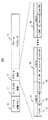
例えば、ITU-T勧告G.984.3の8.2章の規定では、複数のONUからOLTに向けて伝送される信号は上り信号と呼ばれ、プリアンブル、デリミタ、ペイロード信号より構成されており、また同勧告8章の図8-2に示すように、各上り信号の直前には前のバースト信号との衝突防止のためにガードタイムが設定される。一方、同勧告8.1章の規定によれば、該OLTより該複数のONUに向けて送信される信号は下り信号と呼ばれ、フレーム同期パタン、PLOAM領域、US Bandwidth MAP領域、フレームペイロードから構成されている。
For example, according to the provisions of 8.2 of ITU-T recommendation G.984.3, signals transmitted from multiple ONUs to OLT are called upstream signals, and are composed of preamble, delimiter, and payload signal. As shown in Figure 8-2 in
OLTは同勧告8.1.3.6章に示すようにUS BandWidth MAPと呼ばれる領域を用いて、各ONUの上り信号送信許可タイミングを指定する。US BandWidth MAP領域は送信許可の開始を指定するStart値と終了を指定するEnd値を備えており、それぞれバイト単位の指定が行われる。この値を、送信を許可するという意味でグラント値とも呼ぶ。そして、End値と次のStart値の差は、上り無信号領域であり、上記ガードタイムに対応する。なお、個々のONUにはT-CONTと呼ばれる複数の帯域割り当て単位が割り付け可能であり、上記上り送信許可タイミングの指定はT-CONT毎に行われる。 The OLT specifies the upstream signal transmission permission timing of each ONU using an area called US BandWidth MAP as shown in Chapter 8.1.3.6. The US BandWidth MAP area has a Start value that specifies the start of transmission permission and an End value that specifies the end, and each is specified in units of bytes. This value is also called a grant value in the sense that transmission is permitted. The difference between the End value and the next Start value is an upstream no-signal area and corresponds to the guard time. Each ONU can be assigned a plurality of band allocation units called T-CONT, and the designation of the uplink transmission permission timing is performed for each T-CONT.
上記ITU-T勧告G.984.3によると、グラントは下り信号を構成する125マイクロ秒フレームの先頭付近で対応するONUへのグラントを一括して送信するよう規定されている。言い換えると、OLTは125マイクロ秒周期で各ONUに対しグラントを送信しなければならず、各ONUも125マイクロ秒の周期で、他のONUと伝送路を時分割により共有して使用する。 According to the ITU-T recommendation G.984.3, the grant is specified to collectively send grants to corresponding ONUs near the beginning of the 125 microsecond frame constituting the downstream signal. In other words, the OLT must transmit a grant to each ONU with a period of 125 microseconds, and each ONU also uses a transmission path in a time-sharing manner with other ONUs with a period of 125 microseconds.
このとき、OLTが上述のDBA処理を125マイクロ秒周期で行なえば、各ONUに割り当てた帯域をそのままStart値、End値に反映させてグラント信号を送信することができる。しかし、実際のOLTは必ずしも125マイクロ秒という短い周期でDBA処理を行なわず、例えば0.5ミリ秒や1.0ミリ秒といった、グラントの周期よりも長い周期でDBA処理を行なう。 At this time, if the OLT performs the above-described DBA processing at a cycle of 125 microseconds, it is possible to transmit the grant signal by directly reflecting the bandwidth allocated to each ONU in the Start value and the End value. However, an actual OLT does not necessarily perform DBA processing with a short cycle of 125 microseconds, and performs DBA processing with a cycle longer than the grant cycle, such as 0.5 milliseconds or 1.0 milliseconds.
このようにDBA処理の時点でOLTは、125マイクロ秒のグラント周期に収まるデータ長を超えて各ONUに送信許可するデータ長を配分する。このためグラントを与える段階でOLTは、DBA処理で決定したデータ長を125マイクロ秒単位の複数のフレームに分割して、各125マイクロ秒フレーム内でStart値とEnd値を指定する処理を行なう。 In this way, at the time of DBA processing, the OLT allocates the data length permitted to be transmitted to each ONU exceeding the data length that fits in the 125 microsecond grant period. Therefore, at the stage of granting, the OLT divides the data length determined by the DBA process into a plurality of frames in units of 125 microseconds, and performs processing for designating the Start value and End value in each 125 microsecond frame.
OLTがDBA処理により1つのONUに与えたデータ長を、複数の125マイクロ秒フレームに分割する場合、分割された各グラントのフレームにはヘッダが付される。DBAの時点でOLTが各ONUに割り当てたデータ長には、最初に必ず付される1つのヘッダのデータ長しか組み込まれていない。このため、グラントのフレームが分割されると、余計に付されたヘッダの分だけ、本来そのONUが送信できたはずのデータ長が減ることになる。 When the data length given to one ONU by the OLT by DBA processing is divided into a plurality of 125 microsecond frames, a header is attached to each divided frame of the grant. The data length assigned to each ONU by the OLT at the time of DBA includes only the data length of one header that is always added first. Therefore, when the grant frame is divided, the data length that the ONU should have been able to transmit is reduced by the extra header.
例えば、あるONUがVoIP用に256kbit/sの上り通信帯域を必要としている場合を考える。OLTが0.5ミリ秒周期で帯域割り当て計算(DBA処理)を実行しているとすると、256kbit/sの帯域は0.5ミリ秒に換算して256000×0.0005÷8=16(byte)となる。G-PONにおいては信号をGEMと呼ばれる可変長パケットに収容して伝送する方法が規定されている。ITU-T勧告G.984.3によればGEMヘッダと呼ばれる5バイトのヘッダに可変長フレームの長さとフローラベルを付与したカプセル化が行われる。OLTは最初に必ず付される1つ分のGEMヘッダを考慮して、DBA処理によりこのONUに16+5=21(byte)のデータ長の送信許可を与える。 For example, consider a case where a certain ONU requires a 256 kbit / s upstream communication band for VoIP. Assuming that OLT is performing bandwidth allocation calculation (DBA processing) with a period of 0.5 milliseconds, the bandwidth of 256 kbit / s is converted to 0.5 milliseconds and becomes 256000 × 0.0005 ÷ 8 = 16 (bytes). In G-PON, a method of accommodating a signal in a variable-length packet called GEM and transmitting it is defined. According to ITU-T recommendation G.984.3, encapsulation is performed by adding a variable-length frame length and a flow label to a 5-byte header called a GEM header. OLT considers one GEM header that is always attached first, and grants transmission permission with a data length of 16 + 5 = 21 (bytes) to this ONU by DBA processing.
ONUからOLTへの上り信号の速度が1.244Gbit/sとすると、グラント周期である125マイクロ秒で送信できるデータ長は12000000000×0.000125÷8≒19440(byte)である。21byteのデータ長は、1つのグラント周期のデータ長である19440byteに十分収まる長さであるが、運悪くこの21byteがグラント周期の境界に配置されるとフラグメンテーションにより2つのグラントフレームに分割される。例えばヘッダ5byteとペイロード10byteのグラントフレームと、ヘッダ5byteとペイロード1バイトのグラントフレームの2つに分割されるとフレーム全体の総計は21byteでグラントされたデータ量となるが、実質的にペイロード部分は合計11byteとなり、256kbit/sの帯域を維持するのに必要な16byteのデータ長に対し約31%のデータが未送信となり、通信品質に大きな影響を及ぼす。 If the speed of the upstream signal from ONU to OLT is 1.244 Gbit / s, the data length that can be transmitted in 125 microseconds as the grant period is 12000000000 × 0.000125 ÷ 8≈19440 (bytes). The 21-byte data length is sufficiently long to fit in the data length of one grant period, 19440 bytes, but unfortunately, when 21 bytes are placed at the boundary of the grant period, it is divided into two grant frames by fragmentation. For example, if it is divided into a grant frame with a header of 5 bytes and a payload of 10 bytes and a grant frame with a header of 5 bytes and a payload of 1 byte, the total amount of the frame is 21 bytes, but the payload part is substantially The total is 11 bytes, and about 31% of data is not transmitted for the 16-byte data length required to maintain the 256 kbit / s bandwidth, which greatly affects communication quality.
本発明の目的は、例えばVoIPデータ等遅延による品質劣化が大きいサービスに使用される、データ長が小さい帯域割当時にフラグメンテーションが生じることを防止することができるOLT、ONUおよびPONシステムを提供することにある。 An object of the present invention is to provide an OLT, ONU, and PON system that can prevent fragmentation from occurring when a bandwidth is allocated with a small data length, which is used for a service in which quality degradation due to delay such as VoIP data is large. is there.
本発明では、帯域の小さい信号を優先的にフレームの特定区間たとえばフレーム先頭領域に配置することで上記課題を解決する。 In the present invention, the above-mentioned problem is solved by preferentially arranging a signal having a small band in a specific section of a frame, for example, a frame head region.
G.984.3準拠のG-PONシステムにおいて、特に100kbit/s程度の小さい帯域を割り当てる時に、フラグメンテーションにより通信品質に劣化が生じることを防止できる。 In a G-PON system compliant with G.984.3, it is possible to prevent degradation of communication quality due to fragmentation, particularly when a small band of about 100 kbit / s is allocated.
以下に本発明の実施の形態を説明する。 Embodiments of the present invention will be described below.
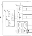
図1に本発明が適用される光アクセス網の構成例を示す。PON19は光スプリッタ/光カプラ等の光分岐器16、通信事業者等の局舎に設置される局側装置であるOLT1、OLT1と光スプリッタを接続する幹線ファイバ17-1、それぞれの加入者宅内やその近くに設置される加入者側装置である複数のONU10、光分岐器12と複数のONU10をそれぞれ接続する複数の支線ファイバ17-2から構成される。OLT1は、幹線ファイバ17-1と光分岐器12および支線ファイバ17-1を介して、たとえば32台のONU10と接続可能である。また、複数のONU10にはそれぞれ、電話15やパーソナルコンピュータ14等のユーザ端末が接続される。PON19はOLT1を介してPSTN(Public Switched Telephone Networks)やインターネット18に接続されて、これら上位のネットワークとの間でデータを送受信する。
FIG. 1 shows a configuration example of an optical access network to which the present invention is applied. PON19 is an
図1には5台のONU10が図示されており、OLT1からONU10の下り方向に伝送される信号11にはそれぞれのONU10宛の信号が時分割多重されている。各ONU10は信号11を受信して、自分宛の信号であるか否かを判定し、さらに自分宛の信号であった場合には信号のあて先に基づいて、電話15やパーソナルコンピュータ14に信号を配信する。
FIG. 1 shows five
一方、ONU10からOLT1の上り方向では、ONU10-1から伝送される信号a、ONU10-2から伝送される信号b、ONU10-3から伝送される信号c、ONU10-4から伝送される信号d.ONU10-nから伝送される信号eは、光分岐器12を通った後に時分割多重されて信号16となりOLT1に到達する。つまりOLT1は、どのタイミングにどのONU10からの信号を受信するかがあらかじめ分かっているため、受信したタイミングに応じて各ONU10からの信号を識別し、処理を行なう。
On the other hand, in the upstream direction from ONU10 to OLT1, signal a transmitted from ONU10-1, signal b transmitted from ONU10-2, signal c transmitted from ONU10-3, signal d transmitted from ONU10-4. The signal e transmitted from the ONU 10-n passes through the
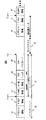
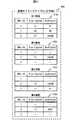
図2にOLT1から各ONU10へ送信される下りPON信号フレームの例を示す。下りフレームはフレーム同期パタン20、PLOAM領域21、グラント指示領域22、フレームペイロード23から構成される。フレームペイロード23には、OLT1からONU10へ向かうユーザ信号が格納され、詳細はITU-T勧告G.984.3に記載されている。グラント指示領域22は、ONU10-1を制御するためのT-CONT#1用信号24、ONU10-2を制御するためのT-CONT#2用信号25、ONU10-nを制御するためのT-CONT#n用信号26より構成される。さらにT-CONT#1用信号24は、T-CONT ID領域27、Start値28およびEnd値29より構成される。
FIG. 2 shows an example of a downstream PON signal frame transmitted from
ここでT-CONT(Trail CONTainer)とはDBAにおける帯域の割当単位であり、例えばONU10が複数の送信バッファを有する場合にはそれぞれのバッファにT-CONTの識別情報であるT-CONT IDを付与して、OLT1からバッファ毎に制御することも可能である。以下の実施例では、1つのONUが1つのT-CONT(バッファ)を有する場合、つまりONU-IDとT-CONT IDが一対一に対応する場合について説明するが、1つのONUに複数のT-CONTがある場合でも本発明を同様に適用することができる。この場合、ONUを識別する情報であるONU−IDとT-CONT IDの関係については、例えば各ONU−IDに対しどのT-CONT IDが含まれるのかを示すテーブルを作成することで対応関係を管理することができる。 Here, T-CONT (Trail CONTainer) is a unit of bandwidth allocation in DBA. For example, when ONU10 has multiple transmission buffers, T-CONT ID, which is T-CONT identification information, is assigned to each buffer. Thus, it is possible to control each buffer from OLT1. In the following embodiment, a case where one ONU has one T-CONT (buffer), that is, a case where ONU-ID and T-CONT ID correspond one-to-one will be described. Even when -CONT is present, the present invention can be similarly applied. In this case, for the relationship between the ONU-ID, which is information for identifying the ONU, and the T-CONT ID, for example, a correspondence relationship can be established by creating a table indicating which T-CONT ID is included for each ONU-ID. Can be managed.
Start値28は各ONUに光信号の送信の開始を許可するタイミングを指示している。また、End値29は送信許可の終了タイミングを指示している。Start値28およびEnd値29はバイト単位で指定される。OLT1は各ONU10に対し、周期的にグラント指示22を含む、上りデータの送信を許可するメッセージを送信し、各ONU10にどれだけの上り通信帯域を使用すれば良いかを指示する。このStart値28やEnd値29は、OLT1がグラント指示を送信する各周期の中で、どのタイミングでデータの送信を開始・終了すれば良いかを示す情報である。なお、End値の代わりに送信すべきデータのデータ長(length)を指定し、Start値のタイミングからlength示されるデータ長だけデータを送信するようOLTからONUに指示しても良い。
The
図3にONU10からOLT1へ送信される上りPON信号フレームの一例を示す。この上りPON信号は、プリアンブル領域30、デリミタ領域31、PLOAM領域32、キュー長領域33、フレームペイロード34より構成される。上記Start値28は、PLOAM領域32の開始位置、すなわちバーストデータ37の開始位置を指示しており、End値29はフレームペイロード34の終了位置を示している。ITU−T勧告G.984.3のガードタイム35は上り信号のフレームペイロード34の終了位置(End値)から次の上り信号のプリアンブル領域30の開始位置までを指す。このように、Start値とEnd値が指し示すデータ位置の間には、ガードタイム35やプリアンブル領域30、デリミタ領域31が介在するため、前のEnd値と次のStart値の間には数バイトの間隔が生じる。
FIG. 3 shows an example of an upstream PON signal frame transmitted from the
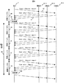
図4に、Start値28とEnd値29を決定および通知する処理のシーケンスを示す。OLT1は、グラント指示22を含む送信許可メッセージ40を各ONU10-1〜10-3に向けて送信する。また、この送信許可メッセージ40には各ONU10の送信キューに、どれだけ未送のデータが溜まっているかの報告を要求する情報も含まれている。各ONU10-1〜10-3は、グラント指示22のStart値28とEnd値29で指定されたタイムスロットを用いて送信キューに溜まったデータを送信するとともに、送信キューにどれだけのデータが溜まっているかという情報を、上りメッセージ41に含まれるキュー長領域33を用いてOLT1へ送信する。
FIG. 4 shows a processing sequence for determining and notifying the
OLT1は、各ONU10-1〜10-3から報告を受けた未送信データ量の情報から、各ONU10にどれだけのデータ量の送信を許可するかを決定するDBA処理42を行なう。このDBA処理42では、各ONU10-1〜10-3の未送信データ量の他、ONUごとに最低限割り当てることが保証されている帯域パラメータ等の情報があればそのような各種の情報も用いて、各ONUに次回送信を許可するデータ量を決定する。
The
図4では、OLT1はグラント周期45〜48ごとにDBA処理を行なわず、複数のグラント周期に対しまとめてDBA処理を行なっている。このためOLT1は、例えば直前に受けた未送信データ量報告41等を用いて、1回のDBA処理で複数のグラント周期における各ONUのStart値28、End値29を決定する。以降、本実施例ではDBA周期が0.5msであり、グラント周期が125μsである場合を例にとって説明を行なうが、当然DBA周期とグラント周期はこれ以外の値を取っても良い。
In FIG. 4,
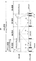
図5は、例えば0.5msの周期でDBA処理を実行する場合に、このDBA周期に含まれる4つのグラント周期で、各ONU#1〜#3からデータが送信される様子を示している。DBA周期が0.5msとすると、その中には125μsのグラント周期が4つ含まれる。ここで、上り信号の速度を例えば約1.2Gbit/sとすると、DBA周期である0.5msの間に送信できるデータ長は77760byteであり、1つのグラント周期である125μsの間に送信できるデータ長は19440byteとなる。
FIG. 5 shows how data is transmitted from each of the
OLT1は0.5msの間に、ONU#1に50byteのデータ50、ONU#2に63000byteのデータ51、ONU#3に25byteのデータ52の送信許可を決定している。しかしグラント周期は125μsであるため、OLT1は各ONU#1〜#3に対し、19440byteごとにデータの送信タイミングを指示しなければならない。送信許可を与える順番は、例えばONUの番号順とすると、OLT1はグラントの第1周期でONU#1にデータ53の送信許可を与え、ONU#2に対しては第1周期の残りでデータ54、第2周期の全てでデータ55、第3周期の一部でデータ56の送信許可をそれぞれ与える。そしてOLT1は、ONU#3に対して、グラントの第3周期の残り一部でデータ57、第4周期の一部を用いてデータ58の送信許可を与える。
OLT1 determines to permit transmission of 50 bytes of
この図の例では、ONU#2とONU#3のデータがグラント周期の境界にまたがり複数のデータに分割されるフラグメンテーションという事象を起こしている。例えばONU#2のデータについては、DBA時はデータ51であったものが、グラント時にはデータ54、55、56の3つに分割されてONU#2から送信されることになる。同様にONU#3のデータについては、DBA時はデータ52であったものが、グラント時にはデータ57と58の2つに分割されている。データが分割されると、それぞれのデータにはGEMヘッダという5byteのデータ長のヘッダが付される。図5では、分割されたONU#3のデータ57、58のうち、データ先頭の黒塗りの部分が図3におけるGEMヘッダ34であり、白抜きの部分が図3におけるGEMペイロード35に相当する。なお、図3のようにPLOAM領域32やキュー長領域33もGEMペイロードに付される場合は、GEMヘッダ34の5byteのみが付される場合よりもさらに送信できるデータ量が制限されることになる。
In the example of this figure, a phenomenon called fragmentation occurs in which
OLT1はデータの最初に1つのGEMヘッダが付されることを考慮して、各ONUに送信を許可するデータ長を割り当てる。しかし、OLT1はデータのフラグメンテーションは想定していない。このため、ONU#3が20byteの未送信データ長を報告した場合、OLT1はヘッダ分5byteを付加した25byteのデータの送信許可を与える。ここで図5に示すように、フラグメンテーションが生じるとONU#3は許可されたデータ長のうちGEMヘッダのために余分に使用した5byte分のデータを送信できず、20byteのデータを送信する必要があるところ、2つのGEMヘッダを除く15byteのデータしか送信できない。
OLT1 assigns a data length allowing transmission to each ONU in consideration of the fact that one GEM header is added at the beginning of the data. However, OLT1 does not expect data fragmentation. For this reason, when
本来このDBA周期で送信すべきであった残りの5byteは、次のDBA周期で送信されることになる。この例ではDBA周期が0.5msであるが、DBA周期がこれより長い場合は残りのデータの送信遅延がさらに大きくなる。同様のことはONU#2についても生じるが、ONU#2の送信許可データ長は63000byteと大きいため、10byte前後のデータがGEMヘッダにより送信できなくなったとしても、影響は小さい。これに対してONU#3は20byteに対する5byte、つまり全データの25%を送信できなかったことになり、多大な影響を被ることになる。
The remaining 5 bytes that should have been transmitted in this DBA cycle are transmitted in the next DBA cycle. In this example, the DBA cycle is 0.5 ms, but if the DBA cycle is longer than this, the transmission delay of the remaining data is further increased. The same thing occurs with
このため本実施例では、DBA処理によりOLT1から割り当てられたバイト長の小さいONUが、グラント周期をまたいで送信許可を与えられることの無いように、OLT1がONUに送信許可を与える順番を変更する。 For this reason, in this embodiment, the order in which OLT1 gives transmission permission to ONUs is changed so that ONUs with a small byte length allocated from OLT1 by DBA processing are not permitted to send transmissions across the grant period. .
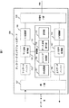
図6はOLTのハードウェア構成の一例である。OLT200は、装置全体の動作を管理する制御ボード603と、それぞれネットワークに接続されて信号の送受信を行なう複数のネットワークインタフェースボード600、601、602を有する。制御ボード603はメモリ609やCPU608を有し、HUB610を介して各ネットワークインタフェースボードを制御する。各ネットワークインタフェースボードは、ONUとの間で光信号の送受信を行なう光信号IF(InterFace)部606や、インターネット等の上位網との間で信号の送受信を行なう網IF(InterFace)部607、ONUと上位網との間における信号の送受信に必要な処理を行なうCPU604やメモリ605を有する。本実施例における各種処理は、例えばメモリ605に格納されたプログラムをCPU604が実行するなどして機能する。もしくは、必要に応じて各処理に特化した専用のハードウェア(LSI等)を用意し、これにより処理を実行しても良い。なお、OLT1のハードウェア構成はこれに限られることなく、適宜必要に応じて様々な実装が行われて良い。
FIG. 6 shows an example of the hardware configuration of the OLT. The OLT 200 includes a
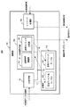
図7はネットワークインタフェースボード600の一構成例である。下りデータバッファ701は、上位網18から受信したデータを一時的に蓄える。下り信号処理部702は、上位網18からの光信号をPON19に中継するために必要な処理を行なう。E/O変換部703は、上位網18からの電気信号を光信号に変換する。O/E変換部704は、PON19から受信した光信号を電気信号に変換する。上り信号処理部705は、PON19からの信号を上位網18に中継するために必要な処理を行なう。上りデータバッファは、上位網18へ送出するデータを一時的に蓄える。
FIG. 7 shows a configuration example of the
制御部700は、複数のONU10と通信を行なうために必要な各種処理を実行する機能を有する。DBA処理部707は、あらかじめ定められたDBA周期毎に、その周期内において複数のONU10のそれぞれにどれだけの通信帯域を割り当てるかを決定する動的帯域割当処理を行なう。この通信帯域は、1つのDBA周期中に送信できる総バイト長内で、どれだけのバイト長を各ONU10に割り当てるかを表わす。レンジング処理部708は、ONUとのデータ送受信に先立って、各ONUにレンジング信号を送信し、当該信号に対する返答を受信するまでの時間を測定することでOLT1と各ONU10の間の距離を測定し、送信遅延時間を決定する。OLT1は送信遅延時間を各ONU10に通知し、各ONU10はOLT1からデータの送信を許可されたタイミングに、通知された送信遅延時間を加えてデータを送信する。データ送信許可部709は、DBA処理部707が決定した各ONU10のバイト長に基づき、各ONUがデータ送信を開始すべきタイミングと、送信を終了すべきタイミングをそれぞれバイト長で決定する。記憶部710は、制御部700の処理に必要な情報を記憶する。
The
図8は制御部700の詳細を説明する図である。DBA処理部707は、上り信号に含まれるキュー長領域33から、各ONU10が保持する未送信のデータ量の報告を受信する。DBA処理部707は受信した未送信データ量や、場合によっては各ONU10にかならず割り当てられるよう設定されている通信帯域に基づいて、DBA周期毎に各ONU10に割り当てる通信帯域をバイト長で決定する。DBA処理部707は、各ONUを識別する情報であるONU-IDと割り当てたバイト長を対応付けた割当バイト長テーブル802を作成し、記憶部710に格納する。
FIG. 8 is a diagram for explaining the details of the
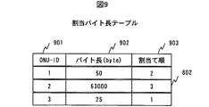
図9は割当てバイト長テーブル802の一例である。割当てバイト長テーブル802は、ONU-ID901と、ONUに割り当てたバイト長902と、グラント時にどの順番で各ONUにタイムスロットを割り当てるかを示す割当て順903の各情報を有する。DBA処理部707が各ONU-ID901に対応するバイト長902を格納した後、データ送信許可部709の送信順序調整部800が各ONUのバイト長を比較し、割当て順903に割当てバイト長が小さなONUから順に番号を付していく。この結果、例えば図9の例ではONU#3、ONU#1、ONU#2の順番でタイムスロットを割り当てることになる。
FIG. 9 is an example of the allocated byte length table 802. The allocation byte length table 802 includes each information of the ONU-
割当てバイト長テーブル802が作成された後、データ送信許可部709の送信タイミング決定部801は、各ONUのバイト長902に、各グラント周期毎にタイムスロットを割り当て、送信タイミングテーブル803を作成し、記憶部710に格納する。
After the allocation byte length table 802 is created, the transmission
図10は送信タイミングテーブル803の一例である。送信タイミングテーブル803は、ONU-ID1001、データの送信開始タイミングを示すStart1002、データの送信終了タイミングを示すEnd1003の各情報を有する。この送信タイミングテーブル803では、図示するグラントの第1周期において、ONU#3、ONU#1、ONU#2の順番でタイムスロットが割り与えられている。そしてONU#2については、第1周期内で全てのデータを送信できないため、グラントの第2、第3、第4周期にデータを分割してタイムスロットが割り与えられている。この送信タイミングテーブル803では、4つのグラント周期の送信タイミング全てを1つのテーブルに記載しており、前のONUのStart1002値がその次のONUのStart値1002より大きいところが周期の境い目となる。
FIG. 10 is an example of the transmission timing table 803. The transmission timing table 803 includes ONU-
図11は、送信タイミングテーブル803の他の構成例である。図11の送信タイミングテーブル803では、グラントの第1周期用のテーブル1101と、第2周期用のテーブル1102と、第3周期用のテーブル1103と、第4周期用のテーブル1104というように、グラント周期ごとに複数のテーブルを備えている。このように、OLT1は送信タイミングテーブル803を複数のテーブルに分割して管理しても良い。
FIG. 11 is another configuration example of the transmission timing table 803. In the transmission timing table 803 of FIG. 11, the grant period table 1101, the second period table 1102, the third period table 1103, the fourth period table 1104, and so on. A plurality of tables are provided for each period. In this way, the
送信タイミング決定部801は、作成した送信タイミングテーブル803の内容に従って、グラント指示22を含む送信許可メッセージを各ONU10に送信し、データの送信タイミングを通知する。
The transmission
図12は、制御部700の処理フローチャートの一例である。まず、制御部700はDBA周期毎に、各ONUからの未送信データ量の報告や、あらかじめ最低限使用可能な帯域を設定されている場合は、当該帯域の情報を用いて、0.5msのDBA周期内で各ONUに送信を許可するデータ量をバイト長で決定し(1201)、当該情報を割当てバイト長テーブル802として記憶部710に格納する(1202)。
FIG. 12 is an example of a process flowchart of the
次にデータ送信許可部709は、割当てバイト長テーブル802のバイト長902を参照し、バイト長が小さい順にONUをソートする(1203)。このとき、上述のように送信順序調整部800が割当てバイト長テーブル802の割当て順903に、割当て順序を記載しても良いし、もしくはONUをバイト長でソートする手間を省いて、タイムスロットを割り当てていないONUの中でバイト長902が最小のものを見つけ次第、次のステップ1204を順次実行するようにしても良い。
Next, the data
DBA処理部707が各ONUに割り当てたバイト長902の大きさを確認したデータ送信許可部709は、バイト長902が小さいONUから順番に、DBA周期に含まれる複数のグラント周期を用いて各ONUにタイムスロットを割り当てる(1204)。この実施例では0.5msのDBA周期に125μs周期のグラント周期が4つ含まれるため、4つのグラント周期分のタイムスロットを用いてデータ送信タイミングを決定する。
The data
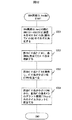
図13は、図12のフローチャートにおけるステップ1204の実施例をさらに詳細に説明するものである。ここでは、図9の割当バイト長テーブル802に対してこのフローチャートの処理を実行することで、図10の送信タイミングテーブル803が作成される過程を説明する。最初に送信タイミング決定部801は、割当バイト長テーブル802を参照し、この中で一番バイト長902の小さいONUをONU-ID901が3であるONU#3と特定する(1301)。このONU#3の特定には、例えば割当バイト長テーブル802の割当て順903の情報を用いることができる。
FIG. 13 explains the embodiment of
次に送信タイミング決定部801は、特定したONU#3のバイト長902を参照し(1302)、その値25byteが、現在のグラント周期である第1周期のバイト長19440byteに収まるデータ量であるか否かを判断する(1303)。この場合、ONU#3のデータは第1周期内に収まるため、第1周期内でONU#3のStart値を12byte、End値を37byteと決定する(1304)。送信タイミング決定部801は全てのONUにタイムスロットを分配したか否かを調べ(1305)、まだONU#1とONU#2が残っているため処理を続行する。
Next, the transmission
データ送信許可部709は、残りのONUのうちバイト長902が小さいONUをONU-ID901が1であるONU#1であると特定し(1306)、ONU#1のバイト長902を参照し(1302)、その値50byteが、現在のグラント周期である第1周期のバイト長に収まるか否かを判断する(1303)。このとき、第1周期は既にONU#3がEnd値である37byteまでを使用しているため、この37byte分を19440byteから差し引いた19403byteの中に50byteが収まるか否かを判断する。
The data
この場合、ONU#1のデータは第1周期内に収まるため、第1周期内でONU#1のStart値を49byte、End値を99byteと決定する(1304)。なお、図3に示したように、前後する上り信号のEnd値とStart値の間には、ガードタイムやプリアンブル領域30、デリミタ領域31が介在するため、送信タイミング決定部801はこれらが介在できるようONU#3のEnd値37byteとの間に間隔を空けて、ONU#1のStart値を例えば49byteと適宜設定する。
In this case, since
送信タイミング決定部801はONU#2が残っていることを確認し(1305、1306)、そのバイト長902を割当バイト長テーブル802から参照する(1302)。ONU#2のバイト長は63000byteであり、現在のグラント周期である第1周期の残りのバイト長は、19440byteから直前に割り当てを行なったONU#1のEnd値である99byteを差し引いた19341byteであるため、送信タイミング決定部801はONU#2のデータが第1周期内に収まりきらないと判断する(1303)。このとき送信タイミング決定部801は、第1周期の残りのタイムスロット全てをONU#2に割り与えて、ONU#2の第1周期におけるStart値を111byte、End値を19440byteと設定する(1306)。この時点でタイムスロットをまだ割り当てられていないONU#2のデータ長は63000-19440+111=43671(byte)である。
The transmission
送信タイミング決定部801は、まだ第2周期以降が残っていることを確認し(1307)、ONU#2のバイト長902の残り43671byteが、第2周期のバイト長19440byteに収まるか否かを判断する(1308)。この場合収まらないので、送信タイミング決定部801は第2周期のタイムスロット全てをONU#2に与えて、ONU#2の第2周期におけるStart値を12byte、End値を19440byteとする。この時点でタイムスロットをまだ割り当てられていないONU#2のデータ長は43671-19440+12=24243(byte)である。
The transmission
さらに送信タイミング決定部801は、まだ第3周期以降が残っていることを確認し(1307)、ONU#2のバイト長902の残り24243byteが、第3周期のバイト長19440byteに収まるか否かを判断する(1308)。この場合収まらないので、送信タイミング決定部801は第3周期のタイムスロット全てをONU#2に与えて、ONU#2の第3周期におけるStart値を12byte、End値を19440byteと設定する(1306)。この時点でタイムスロットをまだ割り当てられていないONU#2のデータ長は24243-19440+12=4815(byte)である。
Further, the transmission
そして送信タイミング決定部801は、まだ第4周期以降が残っていることを確認し(1307)、ONU#2のバイト長902の残り4815byteが、第3周期のバイト長19440byteに収まるか否かを判断する(1308)。この場合収まるので、送信タイミング決定部801はONU#2の第4周期におけるStart値を12byte、End値を4827byteと設定する(1304)。送信タイミング決定部801は、これで全てのONUにタイムスロットを配分したことを確認し(1305)、タイムスロット割り当て処理を終了する。
Then, the transmission
図14は、本実施例のOLT1によって各ONUのデータ送信タイミングが整列される様子を説明するものである。図5と同様に、DBA処理部707はONU#1に50byteのデータ50を、ONU#2に63000byteのデータ51を、ONU#3に25byteのデータ52をそれぞれ割り当てている。本実施例の処理手順に従いタイムスロットを割り当てると、第1周期にはONU#3とONU#1のデータ全てが含まれるため、これらONUが送信を希望する少量のデータは分割されることなく送信を許可されたデータ長を全て送信することができる。なお、ONU#2に関してはグラント周期にまたがり4つのデータに分割されてしまい、分割されたデータの先頭にそれぞれ付与されるヘッダ情報の分だけ送信できるデータ量が減る。しかし、ONU#2はもとのデータ量が多量であるため、送信データ量がヘッダの分だけ減少してもデータ送信全体に与える影響は微小である。
FIG. 14 illustrates how the data transmission timings of the ONUs are aligned by the
なお、以上の実施例では、割当てられたバイト長902が小さいONUから順番にタイムスロットを割り当てる場合を説明したが、本発明はバイト長902の大きさを確認して、グラント周期の境界に小さなバイト長902のデータが配置されることを防ぐことを目的としているため、バイト長の小さなものから厳密に順序付けてタイムスロットを割り当てること自体は必要では無い。例えば、バイト長902に閾値を設け、その閾値以下のONU群は優先してタイムスロットを決定し、閾値より大きいONU群はその後でタイムスロットを決定するようにしても良い。この場合、それぞれのONU群の中では、厳密にバイト長が小さいもの順に並べてタイムスロットを決定する必要は必ずしも無く、例えば小さい方のONU群が1つのグラント周期内でタイムスロットを割り当てられるのであれば、このONU群の中ではバイト長902とタイムスロット割り当て順序が逆転しているものがあっても良い。
In the above embodiment, a case has been described in which time slots are allocated in order starting from an ONU having a
別の実施例として、バイト長902の小さい順にONUを並べて、1つのグラント周期内に割り当てられるONU数を制限することで、バイト長の小さなONUの送信データが分割される確率をさらに小さくする方法も考えられる。
As another example, by arranging ONUs in ascending order of
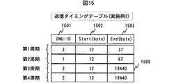
図15は、本実施例における送信タイミングテーブル1500である。この実施指令では、各グラント周期ごとに1つのONUだけタイムスロットを割り当てている。 FIG. 15 is a transmission timing table 1500 in the present embodiment. In this execution command, one ONU is assigned a time slot for each grant period.
図16は、1つのグラント周期内に1つだけONUを割り当てる場合の、送信タイミング決定部801が実行するタイムスロット割り当て処理のフローチャートである。図13のフローチャートと大きく異なる部分は、図14のフローチャート中ステップ1306の処理を、図15のフローチャートではステップ1506〜1508とすることで、新たなONUにタイムスロットを割り当てるたびに、グラント周期も新たなものにする点である。
FIG. 16 is a flowchart of time slot allocation processing executed by the transmission
図9の割当バイト長テーブル802に、図16のフローチャート処理を適用することで、図15に示す送信タイミングテーブル1500が作成される過程を説明する。バイト長902が最も小さいONU#3について、グラントの第1周期でStart値を12byte、End値を37byteとし(1604)、まだONU#1とONU#2が残っていることを確認する(1605)処理までは、図13のフローチャートと同様である。
The process of creating the transmission timing table 1500 shown in FIG. 15 by applying the flowchart processing of FIG. 16 to the allocated byte length table 802 of FIG. 9 will be described. For
この後、送信タイミング決定部801は、まだグラントの第2〜第4周期が残っていることを確認し(1606)、ONU#3の次にバイト長902が小さいONUがONU#1であると特定する(1607)。送信タイミング決定部801はONU#1のバイト長902を参照し(1608)、そのバイト長50byteが次のグラント周期である第2周期のバイト長19440byteに収まるか否かを判断する(1611)。この場合収まるので、送信タイミング決定部801は、ONU#1の送信タイミングとして第2周期のStart値12byteとEnd値62byteを割り当てる(1604)。
Thereafter, the transmission
次に送信タイミング決定部801は、まだONU#2にタイムスロットを割り当てておらず(1605)、グラントの第3〜第4周期が残っていることを確認し(1606)、ONU#1の次にバイト長902が小さいONUがONU#2であると特定する(1607)。送信タイミング決定部801はONU#2のバイト長902を参照し(1608)、そのバイト長63000byteが次のグラント周期である第3周期のバイト長19440byteに収まるか否かを判断する(1611)。この場合収まらないので、送信タイミング決定部801は、ONU#2の第3周期における送信タイミングとしてStart値12byteとEnd値19440byteを割り当てる(1609)。この時点でONU#2のタイムスロットを割り当てられていないデータ長は63000-19440+12=43572(byte)である。
Next, the transmission
送信タイミング決定部801は、グラントの第4周期がまだ残っていることを確認し(1610)、ONU#2の残り43572byteを第4周期のバイト長19440byteに収められるかどうか判断する(1611)。この場合収まらないので、送信タイミング決定部801は、ONU#2の第4周期における送信タイミングとしてStart値12byteとEnd値19440byteを割り当てる(1609)。この時点でONU#2のタイムスロットを割り当てられていないデータ長は43572-19440+12=24144(byte)である。
The transmission
そして送信タイミング決定部801は、このDBA周期にグラント周期がもう残っていないと判断し(1610)、このDBA周期におけるタイムスロットの割り当て処理を終了する。
Then, the transmission
このように、1つのグラント周期を使用するONUの数を制限すれば、割当バイト長テーブル802においてバイト長902が小さなONUは最初の方のグラント周期内に確実に収められるため、これらバイト長902の小さなONUのデータがフラグメンテーションを生じる確率はさらに減少する。ONU#2に関してはOLTから使用を許可されたデータ長63000byteのうち、24144byteを使えないこととなるが、サイズのより小さなデータの一部が欠落した場合に生じる影響と、サイズのより大きなデータの一部が欠落した場合に生じる影響の大きさを比較して、サイズのより小さなデータが欠落する事態の方が影響大とすれば、本実施例の方法も有効である。
In this way, if the number of ONUs that use one grant period is limited, ONUs having a
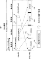
図17は、本実施例のOLT1によって各ONUのデータ送信タイミングが整列される様子を説明するものである。図5と同様に、DBA処理部707はONU#1に50byteのデータ50を、ONU#2に63000byteのデータ51を、ONU#3に25byteのデータ52をそれぞれ割り当てている。本実施例の処理手順に従いタイムスロットを割り当てると、第1周期にはONU#3のデータ全てが、第2周期にはONU#1のデータ全てが確実に全て含まれるため、これらONUが送信を希望する少量のデータは分割されることなくデータ長を全て送信することができる。
FIG. 17 illustrates how the data transmission timings of the ONUs are aligned by the
なお、図15、16、17に示す実施例では、1つのグラント周期に1つのONUだけをあてはめる場合について説明したが、ONUの数に上限を設けて、1つのグラント周期に複数のONUをあてはめるようにしても良い。 In the embodiments shown in FIGS. 15, 16, and 17, the case where only one ONU is applied to one grant period has been described. However, an upper limit is set on the number of ONUs and a plurality of ONUs are applied to one grant period. You may do it.
以下、実施例1や実施例2に共通する効果を説明する。フラグメンテーションは、帯域割当て領域が、125マイクロ秒フレームをまたがる時に発生するが、100kbit/s程度の帯域の小さい信号は1つの125マイクロ秒フレーム内に数100個が収容できるため、フラグメンテーションが発生しにくい。実際、インターネットアクセス等のデータサービスにおいて、上りデータを送信する機会は限られるため、多数のユーザは持続的に発生するVoIP信号のような100kbit/s程度の小さい帯域のデータを送信する時間が圧倒的に長い。したがって、大多数のユーザは1つの125マイクロ秒フレーム内にフラグメンテーションを発生させることなく収容され、数名のユーザのみがバースト的に数100Mbit/sの帯域を使用して、フラグメンテーションを伴う場合が通常と考えられる。したがって、本実施例1又は2によれば大多数のユーザに満足いく通信サービスを提供することができる。また、バースト的に大きなデータを送信するユーザにとっても、大量のデータのごく一部に送信の遅延が生じても、そのユーザが提供を受ける通信サービス全体からするとその影響は小さく問題とならない。 Hereinafter, effects common to the first and second embodiments will be described. Fragmentation occurs when the bandwidth allocation region spans 125 microsecond frames, but since a signal with a small bandwidth of about 100 kbit / s can accommodate several hundred signals within one 125 microsecond frame, fragmentation is unlikely to occur. . In fact, in data services such as Internet access, the opportunity to transmit upstream data is limited, so many users overwhelm the time to transmit data in a small band of about 100 kbit / s, such as VoIP signals that are generated continuously. Long. Therefore, the majority of users are accommodated without generating fragmentation within one 125 microsecond frame, and only a few users are usually accompanied by fragmentation using a bandwidth of several hundred Mbit / s in bursts. it is conceivable that. Therefore, according to the first or second embodiment, a satisfactory communication service can be provided to the majority of users. In addition, even for a user who transmits a large amount of data in a burst manner, even if a transmission delay occurs in a small part of a large amount of data, the influence is small and does not cause any problem in terms of the entire communication service provided by the user.
1 OLT
10 ONU
700 制御部
707 DBA処理部
709 データ送信許可部
800 送信順序調整部
801 送信タイミング決定部
802 割当てバイト長テーブル
803 送信タイミングテーブル
1 OLT
10 ONU
700
Claims (8)
第1の周期で、前記複数の加入者装置夫々に送信を許可するデータ長を決定する動的帯域割当部と、
前記動的帯域割当部が決定した送信を許可するデータ長に基づいて、前記複数の加入者側装置がデータを送信する順番を決定し、該決定順番で前記第1の周期よりも短い複数の第2の周期内でのデータ送信タイミングを、前記複数の加入者側装置にそれぞれ決定するデータ送信許可部とを備え、
前記データ送信許可部は、前記動的帯域割当部が決定した送信を許可するデータ長に基づいて、ある加入者側装置のデータを送信するタイミングが隣接する複数の第2の周期に跨ることを防止して前記複数の加入者側装置がデータを送信する順番とタイミングとを決定することを特徴とする局側装置。 In a station side device connected to a plurality of subscriber side devices via an optical branching unit
A dynamic bandwidth allocating unit that determines a data length permitted to be transmitted to each of the plurality of subscriber devices in a first period;
Based on the data length that permits transmission determined by the dynamic bandwidth allocator , the plurality of subscriber-side devices determine an order of transmitting data , and a plurality of shorter than the first period in the determination order A data transmission permission unit for determining the data transmission timing within the second period for each of the plurality of subscriber side devices,
The data transmission permission unit, based on the data length permitted transmission by the dynamic band allocation unit, that the timing of transmitting data of a certain subscriber side device spans a plurality of adjacent second periods A station side apparatus characterized in that the order and timing of transmission of data by the plurality of subscriber side apparatuses are determined .
前記データ送信許可部は、前記送信を許可するデータ長が小さな前記加入者側装置から順番に、前記複数の第2の周期内でのデータの送信タイミングを決定することを特徴とする局側装置。 In the station side apparatus of Claim 1,
The data transmission permission unit determines the transmission timing of data within the plurality of second periods in order from the subscriber side device with the smallest data length permitting the transmission. .
前記第2の周期は、前記第1の周期を同じ長さの複数の周期に分割したものであることを特徴とする局側装置。 In the station side apparatus of Claim 1,
The station side apparatus characterized in that the second period is obtained by dividing the first period into a plurality of periods having the same length.
前記複数の加入者側装置とGigabit-capable Passive Optical Networks(G-PON)を形成し、前記第2の周期は125マイクロ秒であることを特徴とする局側装置。 In the station side apparatus of Claim 1,
A station-side device that forms a Gigabit-capable Passive Optical Network (G-PON) with the plurality of subscriber-side devices, and the second period is 125 microseconds.
前記第1の周期は複数の前記第2の周期を繰り返してなり、前記データ送信許可部は、前記動的帯域割当部が送信を許可したデータ長の小さい前記加入者側装置から順番に、前記第1の周期に含まれる複数の前記第2の周期のうち、早い方の周期を用いて前記送信タイミングを決定することを特徴とする局側装置。 In the station side apparatus of Claim 1,
The first period is formed by repeating a plurality of the second periods, and the data transmission permission unit is configured in order from the subscriber side device having a small data length permitted to be transmitted by the dynamic band allocating unit. The station apparatus, wherein the transmission timing is determined using an earlier cycle among the plurality of second cycles included in the first cycle.
前記データ送信許可部は、ある前記加入者側装置の送信を許可されたデータ長が、1つの前記第2の周期に収まりきらない場合に、当該許可されたデータ長を分割して複数の前記第2の周期を用いて前記送信タイミングを決定することを特徴とする局側装置。 In the station side apparatus of Claim 1,
The data transmission permission unit divides the permitted data length into a plurality of the plurality of the data lengths when the data length permitted to be transmitted by the subscriber side device does not fit in the second period. A station side apparatus that determines the transmission timing using a second period.
前記データ送信許可部は、前記動的帯域割当部が送信を許可したデータ長の小さい前記加入者側装置から順番に、前記第1の周期に含まれる複数の前記第2の周期それぞれに、あらかじめ定められた台数の前記加入者側装置のデータ送信タイミングを決定することを特徴とする局側装置。 In the station side apparatus of Claim 1,
The data transmission permission unit, in advance from each of the plurality of second periods included in the first period, in order from the subscriber side device having a small data length permitted to be transmitted by the dynamic band allocation unit. A station-side device that determines data transmission timing of a predetermined number of the subscriber-side devices.
前記データ送信許可部は、1つの前記第2の周期に対して、1台の前記加入者側装置のデータ送信タイミングを決定することを特徴とする局側装置。 In the station side apparatus of Claim 7,
The station-side apparatus, wherein the data transmission permission unit determines data transmission timing of one of the subscriber-side apparatuses for one second period.
Priority Applications (4)
| Application Number | Priority Date | Filing Date | Title |
|---|---|---|---|
| JP2007124079A JP4416005B2 (en) | 2007-05-09 | 2007-05-09 | Dynamic bandwidth allocation method in PON system |
| US11/829,488 US7889990B2 (en) | 2007-05-09 | 2007-07-27 | Optical line terminal capable of active bandwidth allocation for passive optical network system |
| CN200710141128XA CN101304288B (en) | 2007-05-09 | 2007-08-08 | Optical line capable of distributing effective wideband in passive optical network |
| US12/979,871 US8184977B2 (en) | 2007-05-09 | 2010-12-28 | Optical line terminal capable of active bandwidth allocation for passive optical network system |
Applications Claiming Priority (1)
| Application Number | Priority Date | Filing Date | Title |
|---|---|---|---|
| JP2007124079A JP4416005B2 (en) | 2007-05-09 | 2007-05-09 | Dynamic bandwidth allocation method in PON system |
Publications (2)
| Publication Number | Publication Date |
|---|---|
| JP2008283323A JP2008283323A (en) | 2008-11-20 |
| JP4416005B2 true JP4416005B2 (en) | 2010-02-17 |
Family
ID=39969633
Family Applications (1)
| Application Number | Title | Priority Date | Filing Date |
|---|---|---|---|
| JP2007124079A Expired - Fee Related JP4416005B2 (en) | 2007-05-09 | 2007-05-09 | Dynamic bandwidth allocation method in PON system |
Country Status (3)
| Country | Link |
|---|---|
| US (2) | US7889990B2 (en) |
| JP (1) | JP4416005B2 (en) |
| CN (1) | CN101304288B (en) |
Families Citing this family (41)
| Publication number | Priority date | Publication date | Assignee | Title |
|---|---|---|---|---|
| US8861514B1 (en) * | 2007-09-27 | 2014-10-14 | Marvell International Ltd. | Method and apparatus for egress jitter pacer |
| US7899323B2 (en) * | 2007-09-28 | 2011-03-01 | Verizon Patent And Licensing Inc. | Multi-interface protocol analysis system |
| EP2053763B1 (en) * | 2007-10-26 | 2012-01-11 | Nokia Siemens Networks Oy | Method to diagnose an optical communication network |
| JP5082816B2 (en) | 2007-12-13 | 2012-11-28 | 住友電気工業株式会社 | Station side line concentrator, access control apparatus and computer program thereof |
| EP2429131B1 (en) * | 2008-02-26 | 2013-08-28 | Nippon Telegraph And Telephone Corporation | Bandwidth allocation method and passive optical network system |
| CN101656894B (en) * | 2008-08-20 | 2012-11-21 | 华为技术有限公司 | Packet add/drop multiplexing equipment and data transmission method for same |
| JP5094664B2 (en) * | 2008-09-26 | 2012-12-12 | 株式会社日立製作所 | Passive optical network system and operation method thereof |
| JP5025618B2 (en) * | 2008-10-27 | 2012-09-12 | 日本電信電話株式会社 | Optical communication system, optical communication method, control device, program, and recording medium |
| US20110033189A1 (en) * | 2008-10-29 | 2011-02-10 | Calix Networks, Inc. | Return path compliance in networks |
| US20100208747A1 (en) * | 2009-02-18 | 2010-08-19 | Telefonaktiebolaget L M Ericsson (Publ) | Output demultiplexing for dynamic bandwidth allocation in passive optical networks |
| US8472801B2 (en) | 2009-02-25 | 2013-06-25 | Futurewei Technologies, Inc. | Upgraded bandwidth map for ten gigabit passive optical network |
| WO2010116487A1 (en) * | 2009-04-07 | 2010-10-14 | 株式会社日立製作所 | Optical multiplexing terminating device, passive optical network system, and method for allocating frequency |
| JP4888515B2 (en) * | 2009-04-16 | 2012-02-29 | 住友電気工業株式会社 | Dynamic bandwidth allocating apparatus and method and station apparatus of PON system |
| EP2464043B1 (en) * | 2009-08-03 | 2019-03-13 | Mitsubishi Electric Corporation | Optical line termination, pon system, and data reception processing method |
| JP5331646B2 (en) * | 2009-10-14 | 2013-10-30 | 株式会社日立製作所 | Optical communication system and communication bandwidth control method |
| KR101310906B1 (en) * | 2009-11-30 | 2013-09-25 | 한국전자통신연구원 | Apparatus and method for assigning dynamic bandwidth |
| JP2011166328A (en) * | 2010-02-08 | 2011-08-25 | Kddi Corp | Optical transmission system, optical line terminal and upward transmission control method |
| US8493986B2 (en) * | 2010-05-17 | 2013-07-23 | Cox Communications, Inc. | Service gateways for providing broadband communication |
| JP5669613B2 (en) * | 2011-02-18 | 2015-02-12 | 沖電気工業株式会社 | Dynamic bandwidth allocation method, optical communication network, and station side apparatus |
| JP5728783B2 (en) * | 2011-04-25 | 2015-06-03 | 株式会社オー・エフ・ネットワークス | Transmission apparatus and transmission system |
| CN103596070B (en) * | 2012-08-16 | 2019-02-19 | 中兴通讯股份有限公司 | Configuration information processing method and device |
| JP6027428B2 (en) * | 2012-12-19 | 2016-11-16 | 日本電信電話株式会社 | Optical communication network system and bandwidth control method |
| CN104053076B (en) * | 2013-03-11 | 2019-04-05 | 中兴通讯股份有限公司 | A method and system for improving bandwidth allocation efficiency |
| JP5482931B1 (en) * | 2013-03-18 | 2014-05-07 | 沖電気工業株式会社 | Subscriber side apparatus registration method and optical network system |
| KR102105186B1 (en) * | 2013-03-18 | 2020-04-28 | 한국전자통신연구원 | Optical line terminal of passive optical network, and method for controlling upstream band using the same |
| CN105247807B (en) * | 2013-08-16 | 2018-04-20 | 华为技术有限公司 | Identification method of service bearer entity in multi-wavelength passive optical network (PON) |
| JP6306488B2 (en) * | 2014-10-27 | 2018-04-04 | 日本電信電話株式会社 | Optical communication system and bandwidth allocation method |
| JP6676496B2 (en) * | 2016-07-29 | 2020-04-08 | 日本電信電話株式会社 | Optical network unit, optical network unit, and computer program |
| JP6674883B2 (en) * | 2016-11-01 | 2020-04-01 | 日本電信電話株式会社 | Intra-office optical termination equipment |
| CN113365163B (en) * | 2016-12-30 | 2023-10-20 | 华为技术有限公司 | Bandwidth allocation method, optical line terminal, optical network unit and system |
| WO2018139410A1 (en) * | 2017-01-24 | 2018-08-02 | 日本電気株式会社 | Optical network control device and control method therefor |
| JP6861593B2 (en) * | 2017-07-20 | 2021-04-21 | 日本電信電話株式会社 | Subscriber line end station equipment |
| JP6822996B2 (en) * | 2018-03-13 | 2021-01-27 | 日本電信電話株式会社 | Bandwidth allocation device and band allocation method |
| CN111385677B (en) * | 2018-12-29 | 2023-07-21 | 南京中兴新软件有限责任公司 | Uplink scheduling method and device and network equipment |
| CN112311494B (en) | 2019-07-23 | 2023-12-08 | 华为技术有限公司 | A message transmission method, device and system |
| EP4002862B1 (en) * | 2020-11-12 | 2026-03-25 | Nokia Solutions and Networks Oy | An optical line terminal and an optical network unit |
| CN115225987A (en) * | 2021-04-19 | 2022-10-21 | 华为技术有限公司 | A device control system, method and device based on optical communication |
| CN115225195A (en) * | 2021-04-19 | 2022-10-21 | 华为技术有限公司 | A communication method and communication device |
| CN115834508B (en) * | 2021-09-16 | 2025-07-04 | 华为技术有限公司 | A method for determining a message period and a related device thereof |
| CN114025261B (en) * | 2021-11-03 | 2023-06-09 | 烽火通信科技股份有限公司 | A method and device for automatic allocation of industrial PON network bandwidth |
| CN118369935A (en) * | 2022-02-17 | 2024-07-19 | 华为技术有限公司 | Cooperative transmission in multiple passive optical network (PON) systems |
Family Cites Families (8)
| Publication number | Priority date | Publication date | Assignee | Title |
|---|---|---|---|---|
| US7127167B2 (en) * | 2001-07-05 | 2006-10-24 | Broadcom Corporation | System for spectrum allocation in ethernet-based fiber optic TDMA networks |
| US7796519B2 (en) * | 2001-09-10 | 2010-09-14 | Nippon Telegraph And Telephone Corporation | Dynamic bandwidth allocation circuit, dynamic bandwidth allocation method, optical network unit, PON system, dynamic bandwidth allocation program and recording medium |
| JP3734732B2 (en) | 2001-09-10 | 2006-01-11 | 日本電信電話株式会社 | Dynamic bandwidth allocation circuit, dynamic bandwidth allocation method, dynamic bandwidth allocation program, and recording medium |
| JP4307381B2 (en) | 2002-09-13 | 2009-08-05 | ピーエムシー−シエラ イスラエル リミテッド | Method of operating an Ethernet passive optical network including a network unit having a plurality of entities |
| KR100490901B1 (en) * | 2002-12-02 | 2005-05-24 | 한국전자통신연구원 | Dynamic Bandwidth Allocation Method and Apparatus based on Class of Service over Ethernet Passive Optical Network |
| US7564852B2 (en) * | 2005-07-20 | 2009-07-21 | Cortina Systems, Inc. | Intelligent bandwidth allocation for ethernet passive optical networks |
| JP2007074234A (en) * | 2005-09-06 | 2007-03-22 | Hitachi Communication Technologies Ltd | Transmission equipment |
| TWI276334B (en) * | 2005-09-16 | 2007-03-11 | Ind Tech Res Inst | Methods for allocating transmission bandwidths of a network |
-
2007
- 2007-05-09 JP JP2007124079A patent/JP4416005B2/en not_active Expired - Fee Related
- 2007-07-27 US US11/829,488 patent/US7889990B2/en not_active Expired - Fee Related
- 2007-08-08 CN CN200710141128XA patent/CN101304288B/en not_active Expired - Fee Related
-
2010
- 2010-12-28 US US12/979,871 patent/US8184977B2/en not_active Expired - Fee Related
Also Published As
| Publication number | Publication date |
|---|---|
| US20110091211A1 (en) | 2011-04-21 |
| CN101304288B (en) | 2013-01-09 |
| US7889990B2 (en) | 2011-02-15 |
| JP2008283323A (en) | 2008-11-20 |
| CN101304288A (en) | 2008-11-12 |
| US20080279554A1 (en) | 2008-11-13 |
| US8184977B2 (en) | 2012-05-22 |
Similar Documents
| Publication | Publication Date | Title |
|---|---|---|
| JP4416005B2 (en) | Dynamic bandwidth allocation method in PON system | |
| JP5285766B2 (en) | Optical multiple terminator, passive optical network system, wavelength allocation method | |
| JP5094664B2 (en) | Passive optical network system and operation method thereof | |
| JP4942680B2 (en) | PASSIVE OPTICAL NETWORK SYSTEM, OPTICAL MULTIPLE TERMINAL DEVICE, AND PASSIVE OPTICAL NETWORK SYSTEM COMMUNICATION METHOD | |
| CN102804701B (en) | Optical multiplexing terminal device, wavelength multiplexing passive optical network system, and downstream wavelength transmission method | |
| CN101646106B (en) | Passive optical network system, optical multiplexing terminator and optical network terminal | |
| JP5216656B2 (en) | Passive optical network system and operation method thereof | |
| JP6841919B2 (en) | Data communication system, optical network unit, and baseband device | |
| JP2010074214A (en) | Passive optical network system and optical multiplexed terminator | |
| Bosternak et al. | Approach of the T-CONT allocation to increase the bandwidth in passive optical networks | |
| KR100666989B1 (en) | Traffic scheduling method of EPON system and EPON system | |
| KR100758784B1 (en) | MAC Scheduling Apparatus and Method for Broadband Station in Passive Optical Branch Network | |
| KR100952833B1 (en) | Uplink Bandwidth Allocation Method in ONP of Ethernet Passive Optical Communication Network (EPON) | |
| JP5487293B2 (en) | Passive optical network system and operation method thereof | |
| WO2022269853A1 (en) | Bandwidth allocation device, subscriber line termination device, and bandwidth allocation method |
Legal Events
| Date | Code | Title | Description |
|---|---|---|---|
| A621 | Written request for application examination |
Free format text: JAPANESE INTERMEDIATE CODE: A621 Effective date: 20090316 |
|
| A521 | Written amendment |
Free format text: JAPANESE INTERMEDIATE CODE: A523 Effective date: 20090316 |
|
| A977 | Report on retrieval |
Free format text: JAPANESE INTERMEDIATE CODE: A971007 Effective date: 20090713 |
|
| A131 | Notification of reasons for refusal |
Free format text: JAPANESE INTERMEDIATE CODE: A131 Effective date: 20090728 |
|
| A711 | Notification of change in applicant |
Free format text: JAPANESE INTERMEDIATE CODE: A712 Effective date: 20090911 |
|
| A521 | Written amendment |
Free format text: JAPANESE INTERMEDIATE CODE: A523 Effective date: 20090914 |
|
| TRDD | Decision of grant or rejection written | ||
| A01 | Written decision to grant a patent or to grant a registration (utility model) |
Free format text: JAPANESE INTERMEDIATE CODE: A01 Effective date: 20091104 |
|
| A01 | Written decision to grant a patent or to grant a registration (utility model) |
Free format text: JAPANESE INTERMEDIATE CODE: A01 |
|
| A61 | First payment of annual fees (during grant procedure) |
Free format text: JAPANESE INTERMEDIATE CODE: A61 Effective date: 20091117 |
|
| FPAY | Renewal fee payment (event date is renewal date of database) |
Free format text: PAYMENT UNTIL: 20121204 Year of fee payment: 3 |
|
| FPAY | Renewal fee payment (event date is renewal date of database) |
Free format text: PAYMENT UNTIL: 20131204 Year of fee payment: 4 |
|
| LAPS | Cancellation because of no payment of annual fees |