WO2010114040A1 - Solid electrolyte fuel cell - Google Patents
Solid electrolyte fuel cell Download PDFInfo
- Publication number
- WO2010114040A1 WO2010114040A1 PCT/JP2010/055907 JP2010055907W WO2010114040A1 WO 2010114040 A1 WO2010114040 A1 WO 2010114040A1 JP 2010055907 W JP2010055907 W JP 2010055907W WO 2010114040 A1 WO2010114040 A1 WO 2010114040A1
- Authority
- WO
- WIPO (PCT)
- Prior art keywords
- temperature
- restart
- fuel cell
- atr
- mode
- Prior art date
Links
Images


Classifications
-
- H—ELECTRICITY
- H01—ELECTRIC ELEMENTS
- H01M—PROCESSES OR MEANS, e.g. BATTERIES, FOR THE DIRECT CONVERSION OF CHEMICAL ENERGY INTO ELECTRICAL ENERGY
- H01M8/00—Fuel cells; Manufacture thereof
- H01M8/04—Auxiliary arrangements, e.g. for control of pressure or for circulation of fluids
- H01M8/04298—Processes for controlling fuel cells or fuel cell systems
- H01M8/04313—Processes for controlling fuel cells or fuel cell systems characterised by the detection or assessment of variables; characterised by the detection or assessment of failure or abnormal function
- H01M8/0432—Temperature; Ambient temperature
- H01M8/04373—Temperature; Ambient temperature of auxiliary devices, e.g. reformers, compressors, burners
-
- C—CHEMISTRY; METALLURGY
- C01—INORGANIC CHEMISTRY
- C01B—NON-METALLIC ELEMENTS; COMPOUNDS THEREOF; METALLOIDS OR COMPOUNDS THEREOF NOT COVERED BY SUBCLASS C01C
- C01B3/00—Hydrogen; Gaseous mixtures containing hydrogen; Separation of hydrogen from mixtures containing it; Purification of hydrogen
- C01B3/02—Production of hydrogen or of gaseous mixtures containing a substantial proportion of hydrogen
- C01B3/32—Production of hydrogen or of gaseous mixtures containing a substantial proportion of hydrogen by reaction of gaseous or liquid organic compounds with gasifying agents, e.g. water, carbon dioxide, air
- C01B3/34—Production of hydrogen or of gaseous mixtures containing a substantial proportion of hydrogen by reaction of gaseous or liquid organic compounds with gasifying agents, e.g. water, carbon dioxide, air by reaction of hydrocarbons with gasifying agents
- C01B3/38—Production of hydrogen or of gaseous mixtures containing a substantial proportion of hydrogen by reaction of gaseous or liquid organic compounds with gasifying agents, e.g. water, carbon dioxide, air by reaction of hydrocarbons with gasifying agents using catalysts
- C01B3/382—Multi-step processes
-
- C—CHEMISTRY; METALLURGY
- C01—INORGANIC CHEMISTRY
- C01B—NON-METALLIC ELEMENTS; COMPOUNDS THEREOF; METALLOIDS OR COMPOUNDS THEREOF NOT COVERED BY SUBCLASS C01C
- C01B3/00—Hydrogen; Gaseous mixtures containing hydrogen; Separation of hydrogen from mixtures containing it; Purification of hydrogen
- C01B3/02—Production of hydrogen or of gaseous mixtures containing a substantial proportion of hydrogen
- C01B3/32—Production of hydrogen or of gaseous mixtures containing a substantial proportion of hydrogen by reaction of gaseous or liquid organic compounds with gasifying agents, e.g. water, carbon dioxide, air
- C01B3/34—Production of hydrogen or of gaseous mixtures containing a substantial proportion of hydrogen by reaction of gaseous or liquid organic compounds with gasifying agents, e.g. water, carbon dioxide, air by reaction of hydrocarbons with gasifying agents
- C01B3/38—Production of hydrogen or of gaseous mixtures containing a substantial proportion of hydrogen by reaction of gaseous or liquid organic compounds with gasifying agents, e.g. water, carbon dioxide, air by reaction of hydrocarbons with gasifying agents using catalysts
- C01B3/384—Production of hydrogen or of gaseous mixtures containing a substantial proportion of hydrogen by reaction of gaseous or liquid organic compounds with gasifying agents, e.g. water, carbon dioxide, air by reaction of hydrocarbons with gasifying agents using catalysts the catalyst being continuously externally heated
-
- H—ELECTRICITY
- H01—ELECTRIC ELEMENTS
- H01M—PROCESSES OR MEANS, e.g. BATTERIES, FOR THE DIRECT CONVERSION OF CHEMICAL ENERGY INTO ELECTRICAL ENERGY
- H01M8/00—Fuel cells; Manufacture thereof
- H01M8/02—Details
- H01M8/0271—Sealing or supporting means around electrodes, matrices or membranes
-
- H—ELECTRICITY
- H01—ELECTRIC ELEMENTS
- H01M—PROCESSES OR MEANS, e.g. BATTERIES, FOR THE DIRECT CONVERSION OF CHEMICAL ENERGY INTO ELECTRICAL ENERGY
- H01M8/00—Fuel cells; Manufacture thereof
- H01M8/04—Auxiliary arrangements, e.g. for control of pressure or for circulation of fluids
- H01M8/04223—Auxiliary arrangements, e.g. for control of pressure or for circulation of fluids during start-up or shut-down; Depolarisation or activation, e.g. purging; Means for short-circuiting defective fuel cells
- H01M8/04225—Auxiliary arrangements, e.g. for control of pressure or for circulation of fluids during start-up or shut-down; Depolarisation or activation, e.g. purging; Means for short-circuiting defective fuel cells during start-up
-
- H—ELECTRICITY
- H01—ELECTRIC ELEMENTS
- H01M—PROCESSES OR MEANS, e.g. BATTERIES, FOR THE DIRECT CONVERSION OF CHEMICAL ENERGY INTO ELECTRICAL ENERGY
- H01M8/00—Fuel cells; Manufacture thereof
- H01M8/04—Auxiliary arrangements, e.g. for control of pressure or for circulation of fluids
- H01M8/04223—Auxiliary arrangements, e.g. for control of pressure or for circulation of fluids during start-up or shut-down; Depolarisation or activation, e.g. purging; Means for short-circuiting defective fuel cells
- H01M8/04228—Auxiliary arrangements, e.g. for control of pressure or for circulation of fluids during start-up or shut-down; Depolarisation or activation, e.g. purging; Means for short-circuiting defective fuel cells during shut-down
-
- H—ELECTRICITY
- H01—ELECTRIC ELEMENTS
- H01M—PROCESSES OR MEANS, e.g. BATTERIES, FOR THE DIRECT CONVERSION OF CHEMICAL ENERGY INTO ELECTRICAL ENERGY
- H01M8/00—Fuel cells; Manufacture thereof
- H01M8/06—Combination of fuel cells with means for production of reactants or for treatment of residues
- H01M8/0606—Combination of fuel cells with means for production of reactants or for treatment of residues with means for production of gaseous reactants
- H01M8/0612—Combination of fuel cells with means for production of reactants or for treatment of residues with means for production of gaseous reactants from carbon-containing material
- H01M8/0618—Reforming processes, e.g. autothermal, partial oxidation or steam reforming
-
- H—ELECTRICITY
- H01—ELECTRIC ELEMENTS
- H01M—PROCESSES OR MEANS, e.g. BATTERIES, FOR THE DIRECT CONVERSION OF CHEMICAL ENERGY INTO ELECTRICAL ENERGY
- H01M8/00—Fuel cells; Manufacture thereof
- H01M8/24—Grouping of fuel cells, e.g. stacking of fuel cells
- H01M8/241—Grouping of fuel cells, e.g. stacking of fuel cells with solid or matrix-supported electrolytes
- H01M8/2425—High-temperature cells with solid electrolytes
- H01M8/2428—Grouping by arranging unit cells on a surface of any form, e.g. planar or tubular
-
- H—ELECTRICITY
- H01—ELECTRIC ELEMENTS
- H01M—PROCESSES OR MEANS, e.g. BATTERIES, FOR THE DIRECT CONVERSION OF CHEMICAL ENERGY INTO ELECTRICAL ENERGY
- H01M8/00—Fuel cells; Manufacture thereof
- H01M8/24—Grouping of fuel cells, e.g. stacking of fuel cells
- H01M8/241—Grouping of fuel cells, e.g. stacking of fuel cells with solid or matrix-supported electrolytes
- H01M8/2425—High-temperature cells with solid electrolytes
- H01M8/243—Grouping of unit cells of tubular or cylindrical configuration
-
- H—ELECTRICITY
- H01—ELECTRIC ELEMENTS
- H01M—PROCESSES OR MEANS, e.g. BATTERIES, FOR THE DIRECT CONVERSION OF CHEMICAL ENERGY INTO ELECTRICAL ENERGY
- H01M8/00—Fuel cells; Manufacture thereof
- H01M8/24—Grouping of fuel cells, e.g. stacking of fuel cells
- H01M8/2457—Grouping of fuel cells, e.g. stacking of fuel cells with both reactants being gaseous or vaporised
-
- H—ELECTRICITY
- H01—ELECTRIC ELEMENTS
- H01M—PROCESSES OR MEANS, e.g. BATTERIES, FOR THE DIRECT CONVERSION OF CHEMICAL ENERGY INTO ELECTRICAL ENERGY
- H01M8/00—Fuel cells; Manufacture thereof
- H01M8/24—Grouping of fuel cells, e.g. stacking of fuel cells
- H01M8/2465—Details of groupings of fuel cells
- H01M8/2484—Details of groupings of fuel cells characterised by external manifolds
-
- C—CHEMISTRY; METALLURGY
- C01—INORGANIC CHEMISTRY
- C01B—NON-METALLIC ELEMENTS; COMPOUNDS THEREOF; METALLOIDS OR COMPOUNDS THEREOF NOT COVERED BY SUBCLASS C01C
- C01B2203/00—Integrated processes for the production of hydrogen or synthesis gas
- C01B2203/02—Processes for making hydrogen or synthesis gas
- C01B2203/0205—Processes for making hydrogen or synthesis gas containing a reforming step
- C01B2203/0227—Processes for making hydrogen or synthesis gas containing a reforming step containing a catalytic reforming step
- C01B2203/0233—Processes for making hydrogen or synthesis gas containing a reforming step containing a catalytic reforming step the reforming step being a steam reforming step
-
- C—CHEMISTRY; METALLURGY
- C01—INORGANIC CHEMISTRY
- C01B—NON-METALLIC ELEMENTS; COMPOUNDS THEREOF; METALLOIDS OR COMPOUNDS THEREOF NOT COVERED BY SUBCLASS C01C
- C01B2203/00—Integrated processes for the production of hydrogen or synthesis gas
- C01B2203/02—Processes for making hydrogen or synthesis gas
- C01B2203/0205—Processes for making hydrogen or synthesis gas containing a reforming step
- C01B2203/0227—Processes for making hydrogen or synthesis gas containing a reforming step containing a catalytic reforming step
- C01B2203/0244—Processes for making hydrogen or synthesis gas containing a reforming step containing a catalytic reforming step the reforming step being an autothermal reforming step, e.g. secondary reforming processes
-
- C—CHEMISTRY; METALLURGY
- C01—INORGANIC CHEMISTRY
- C01B—NON-METALLIC ELEMENTS; COMPOUNDS THEREOF; METALLOIDS OR COMPOUNDS THEREOF NOT COVERED BY SUBCLASS C01C
- C01B2203/00—Integrated processes for the production of hydrogen or synthesis gas
- C01B2203/02—Processes for making hydrogen or synthesis gas
- C01B2203/025—Processes for making hydrogen or synthesis gas containing a partial oxidation step
- C01B2203/0261—Processes for making hydrogen or synthesis gas containing a partial oxidation step containing a catalytic partial oxidation step [CPO]
-
- C—CHEMISTRY; METALLURGY
- C01—INORGANIC CHEMISTRY
- C01B—NON-METALLIC ELEMENTS; COMPOUNDS THEREOF; METALLOIDS OR COMPOUNDS THEREOF NOT COVERED BY SUBCLASS C01C
- C01B2203/00—Integrated processes for the production of hydrogen or synthesis gas
- C01B2203/06—Integration with other chemical processes
- C01B2203/066—Integration with other chemical processes with fuel cells
-
- C—CHEMISTRY; METALLURGY
- C01—INORGANIC CHEMISTRY
- C01B—NON-METALLIC ELEMENTS; COMPOUNDS THEREOF; METALLOIDS OR COMPOUNDS THEREOF NOT COVERED BY SUBCLASS C01C
- C01B2203/00—Integrated processes for the production of hydrogen or synthesis gas
- C01B2203/10—Catalysts for performing the hydrogen forming reactions
- C01B2203/1041—Composition of the catalyst
- C01B2203/1047—Group VIII metal catalysts
- C01B2203/1052—Nickel or cobalt catalysts
- C01B2203/1058—Nickel catalysts
-
- C—CHEMISTRY; METALLURGY
- C01—INORGANIC CHEMISTRY
- C01B—NON-METALLIC ELEMENTS; COMPOUNDS THEREOF; METALLOIDS OR COMPOUNDS THEREOF NOT COVERED BY SUBCLASS C01C
- C01B2203/00—Integrated processes for the production of hydrogen or synthesis gas
- C01B2203/10—Catalysts for performing the hydrogen forming reactions
- C01B2203/1041—Composition of the catalyst
- C01B2203/1047—Group VIII metal catalysts
- C01B2203/1064—Platinum group metal catalysts
-
- C—CHEMISTRY; METALLURGY
- C01—INORGANIC CHEMISTRY
- C01B—NON-METALLIC ELEMENTS; COMPOUNDS THEREOF; METALLOIDS OR COMPOUNDS THEREOF NOT COVERED BY SUBCLASS C01C
- C01B2203/00—Integrated processes for the production of hydrogen or synthesis gas
- C01B2203/12—Feeding the process for making hydrogen or synthesis gas
- C01B2203/1258—Pre-treatment of the feed
-
- C—CHEMISTRY; METALLURGY
- C01—INORGANIC CHEMISTRY
- C01B—NON-METALLIC ELEMENTS; COMPOUNDS THEREOF; METALLOIDS OR COMPOUNDS THEREOF NOT COVERED BY SUBCLASS C01C
- C01B2203/00—Integrated processes for the production of hydrogen or synthesis gas
- C01B2203/16—Controlling the process
- C01B2203/1604—Starting up the process
-
- C—CHEMISTRY; METALLURGY
- C01—INORGANIC CHEMISTRY
- C01B—NON-METALLIC ELEMENTS; COMPOUNDS THEREOF; METALLOIDS OR COMPOUNDS THEREOF NOT COVERED BY SUBCLASS C01C
- C01B2203/00—Integrated processes for the production of hydrogen or synthesis gas
- C01B2203/16—Controlling the process
- C01B2203/1609—Shutting down the process
-
- C—CHEMISTRY; METALLURGY
- C01—INORGANIC CHEMISTRY
- C01B—NON-METALLIC ELEMENTS; COMPOUNDS THEREOF; METALLOIDS OR COMPOUNDS THEREOF NOT COVERED BY SUBCLASS C01C
- C01B2203/00—Integrated processes for the production of hydrogen or synthesis gas
- C01B2203/16—Controlling the process
- C01B2203/1614—Controlling the temperature
- C01B2203/1619—Measuring the temperature
-
- C—CHEMISTRY; METALLURGY
- C01—INORGANIC CHEMISTRY
- C01B—NON-METALLIC ELEMENTS; COMPOUNDS THEREOF; METALLOIDS OR COMPOUNDS THEREOF NOT COVERED BY SUBCLASS C01C
- C01B2203/00—Integrated processes for the production of hydrogen or synthesis gas
- C01B2203/16—Controlling the process
- C01B2203/1685—Control based on demand of downstream process
-
- H—ELECTRICITY
- H01—ELECTRIC ELEMENTS
- H01M—PROCESSES OR MEANS, e.g. BATTERIES, FOR THE DIRECT CONVERSION OF CHEMICAL ENERGY INTO ELECTRICAL ENERGY
- H01M8/00—Fuel cells; Manufacture thereof
- H01M8/10—Fuel cells with solid electrolytes
- H01M8/12—Fuel cells with solid electrolytes operating at high temperature, e.g. with stabilised ZrO2 electrolyte
- H01M2008/1293—Fuel cells with solid oxide electrolytes
-
- H—ELECTRICITY
- H01—ELECTRIC ELEMENTS
- H01M—PROCESSES OR MEANS, e.g. BATTERIES, FOR THE DIRECT CONVERSION OF CHEMICAL ENERGY INTO ELECTRICAL ENERGY
- H01M8/00—Fuel cells; Manufacture thereof
- H01M8/04—Auxiliary arrangements, e.g. for control of pressure or for circulation of fluids
- H01M8/04007—Auxiliary arrangements, e.g. for control of pressure or for circulation of fluids related to heat exchange
- H01M8/04014—Heat exchange using gaseous fluids; Heat exchange by combustion of reactants
-
- H—ELECTRICITY
- H01—ELECTRIC ELEMENTS
- H01M—PROCESSES OR MEANS, e.g. BATTERIES, FOR THE DIRECT CONVERSION OF CHEMICAL ENERGY INTO ELECTRICAL ENERGY
- H01M8/00—Fuel cells; Manufacture thereof
- H01M8/04—Auxiliary arrangements, e.g. for control of pressure or for circulation of fluids
- H01M8/04082—Arrangements for control of reactant parameters, e.g. pressure or concentration
- H01M8/04089—Arrangements for control of reactant parameters, e.g. pressure or concentration of gaseous reactants
-
- Y—GENERAL TAGGING OF NEW TECHNOLOGICAL DEVELOPMENTS; GENERAL TAGGING OF CROSS-SECTIONAL TECHNOLOGIES SPANNING OVER SEVERAL SECTIONS OF THE IPC; TECHNICAL SUBJECTS COVERED BY FORMER USPC CROSS-REFERENCE ART COLLECTIONS [XRACs] AND DIGESTS
- Y02—TECHNOLOGIES OR APPLICATIONS FOR MITIGATION OR ADAPTATION AGAINST CLIMATE CHANGE
- Y02E—REDUCTION OF GREENHOUSE GAS [GHG] EMISSIONS, RELATED TO ENERGY GENERATION, TRANSMISSION OR DISTRIBUTION
- Y02E60/00—Enabling technologies; Technologies with a potential or indirect contribution to GHG emissions mitigation
- Y02E60/30—Hydrogen technology
- Y02E60/50—Fuel cells
Definitions
- the present invention relates to a solid oxide fuel cell, and more particularly to a solid oxide fuel cell that generates electric power by electrochemically reacting a fuel gas and an oxidant gas.
- Solid Oxide Fuel Cell uses an oxide ion conductive solid electrolyte as an electrolyte, has electrodes on both sides, supplies fuel gas on one side, and supplies the other This is a fuel cell that operates at a relatively high temperature by supplying an oxidizing agent (air, oxygen, etc.) to the side.
- SOFC Solid Oxide Fuel Cell
- the start processing is not executed from the first start processing routine, but the start processing is executed under the same condition as the control processing at the time when the restart request is made. It has been proposed to move to the point of execution.
- the thermal efficiency is increased by placing the fuel cell stack in a storage container that stores the fuel cell stack, and excess gas is burned in the storage container.
- Proposals have been made that can be heated with combustion gas at a higher temperature than before, and can obtain the amount of heat necessary for steam reforming even during low-load operation.
- a heating operation is performed in which the fuel reformer is heated by the combustion heat of the combustion gas.
- the fuel reformer When the temperature of the fuel reformer rises to a temperature within the temperature range above the partial oxidation reaction start temperature and below the steam reformable temperature, the fuel reformer is cooled by the reaction heat of the partial oxidation reaction and the combustion heat of the combustion gas.
- a partial oxidation reforming reaction (hereinafter referred to as “POX”) is performed by heating. Furthermore, when the temperature of the fuel reformer rises to a temperature range above the steam reformable temperature and below the steady temperature, the reaction heat of the partial oxidation reaction, the combustion heat by the combustion gas, and the heat absorption of the steam reforming reaction are controlled to control the fuel.
- ATR autothermal reforming reaction
- SR steam reforming reaction
- Patent Document 1 and Patent Document 2 described above it is assumed that it is a temperature band in which the POX is operated during normal startup in order to further speed up restart while protecting the cell at restart.
- Patent Document 1 and Patent Document 2 described above it is assumed that it is a temperature band in which the POX is operated during normal startup in order to further speed up restart while protecting the cell at restart.
- the present invention has been made to solve the above-described new problem, and at the time of a stop accompanied by a temperature drop from a high temperature, instead of skipping the POX at the normal start-up, the ATR repeats the operation.
- the solid oxide fuel cell can reduce the burden on the cell to improve durability, and can prevent the effect on the cell, while achieving stable temperature recovery and shortening of start-up time.
- the purpose is to provide (SOFC).
- the present invention is a solid oxide fuel cell that generates electricity by electrochemically reacting a fuel gas and an oxidant gas, and is disposed in a solid oxide fuel cell module.
- a reforming state temperature detector for detecting a reforming state temperature for changing, and a control device for controlling the operation of the fuel cell module, wherein the control device activates the operation of the
- a start control device for controlling, and a stop control device for controlling the stop of the operation of the fuel cell module ignites and burns the fuel gas, and then the reforming state temperature detector.
- combustion operation control is performed to raise the temperature of the reformer by the combustion heat of the fuel gas, and the reformed state temperature is Is within the POX temperature zone below the POX start temperature and below the temperature at which the steam reforming is possible, the POX at normal startup is executed to raise the temperature of the reformer, and the reforming is performed.
- ATR during normal startup is performed to raise the temperature of the reformer
- the normal start-up SR is executed to raise the temperature of the reformer
- the start-up control device further includes the fuel cell module.
- start-up time can be greatly shortened by devised to execute the restart control that actively uses the residual heat remaining in the fuel cell or reformer.
- the restart control that actively uses the residual heat remaining in the fuel cell or reformer.
- the restart control performs restart by POX when the reforming state temperature is lower than a predetermined temperature within the POX temperature band at the normal start-up, and the reforming state temperature is Is over a predetermined temperature within the POX temperature band, the ATR restart is executed.
- the POX since there is no oxidation effect at a temperature lower than a predetermined temperature within the POX temperature range, the POX is executed so that the fuel such as the reformer can be efficiently prevented while preventing the oxidation due to the exothermic reaction by the POX.
- the temperature of the battery module can be recovered, but on the other hand, it is easy to control by not using ATR which requires very minute water control, and it is optimal without causing temperature drop of the reformer etc. due to water supply The temperature can be recovered stably in the state.
- the restart control is performed by performing restart by ATR instead of POX at the time of normal startup when the reforming state temperature is at least within the POX temperature range, and the ATR performed by this restart control. At least a part of the ATR is configured to be different from the ATR at the time of normal activation.
- water supply is performed by executing an ATR different from the ATR at the normal start-up that actively uses the residual heat remaining in the fuel cell or reformer at the time of restart. Accordingly, the temperature drop of the reformer or the like can be suppressed, and the temperature recovery can be performed more appropriately.
- the ATR performed by the restart control is configured to increase the amount of fuel gas supplied compared to the ATR at the time of normal startup.
- the restart control by the ATR in which the supply amount of the fuel gas is larger than the ATR at the time of the normal start is executed, so that it is relatively low by the execution of the ATR with the combustion temperature kept high. Even in the case of water supply in the temperature range, the temperature drop of the reformer or the like can be suppressed and rapid temperature recovery can be achieved.
- the ATR performed in the restart control is configured to increase the supply amount of the oxidant gas as compared with the ATR during the normal startup.
- the restart control by the ATR in which the supply amount of the oxidant gas is larger than the ATR at the normal start-up the exothermic reaction due to the partial oxidation reaction increases, and more quickly.
- the ATR performed by the restart control is configured to reduce the amount of water supplied compared to the ATR at the time of normal startup.
- the present invention configured as described above, it is possible to suppress the temperature drop of the reformer and the like by executing the restart control by the ATR in which the amount of water supplied is smaller than the ATR at the time of normal startup. Even in a relatively low temperature zone, the ATR can be executed with the help of the remaining heat, and a stable temperature increase can be achieved.
- the ATR performed by the restart control is changed to the ATR at the time of normal startup when the reforming state temperature rises by a predetermined temperature or more.
- the ATR performed by the restart control when the ATR is performed while suppressing the burden on the reformer and the like, and the expected temperature increase of the reforming state temperature is achieved.
- the restart control is performed by the ATR while maintaining a predetermined amount without changing the predetermined fuel gas supply amount, oxidant gas supply amount, and water supply amount.
- the temperature is determined by executing the restart by the ATR that maintains a constant amount without changing the predetermined amount of fuel gas, the amount of oxidant gas, and the amount of water. Even in the unstable temperature range where the temperature is low, the temperature recovery of the reformer or the like can be stably performed by preventing the factor that changes the reforming state.
- the restart control executes restart by the first ATR in the POX temperature band at the normal start, and restart by the second ATR in the ATR temperature band at the normal start.
- the first ATR executed and executed by the restart control is configured to reduce the amount of water supplied compared to the second ATR.
- the POX temperature zone at the normal startup is executed by the first ATR with a small amount of water supplied for restarting, and the second ATR temperature zone at the normal startup is executed in the second ATR temperature zone.
- the ATR performed by the restart control is configured such that the initial supply amount of the oxidizing gas is larger than the supply amount of the late oxidizing gas.
- the partial oxidation reforming reaction is made larger than the steam reforming reaction by increasing the amount of air in an area where the temperature is relatively low at the initial stage of restart. The temperature of the fuel cell module can be stably increased while suppressing the temperature drop of the mass device.
- the present invention preferably further includes an oxidant gas heating device for heating an oxidant gas supplied from the oxidant gas supply device to the reformer, and the restart control is performed by the oxidant gas heating device. Then, the heating temperature for heating the oxidant gas is set higher than the ATR at the time of the normal startup, and the restart by the ATR is executed.
- the heating temperature for heating the oxidant gas is set higher than the ATR at the time of the normal startup, and the restart by the ATR is executed.
- the present invention preferably further includes a water supply device that generates pure water and supplies it to the reformer, the water supply device including a water pipe for introducing water into the reformer, and the water supply device.
- a heat retaining device for retaining the temperature of the pipe.
- the present invention preferably further forms an exhaust gas chamber that supports a lower portion of a cell assembly including a plurality of fuel cells and exhausts exhaust gas generated by combustion of fuel gas and oxidant gas.
- the heat retaining device is configured to suppress the temperature drop of the water supplied to the reformer by arranging the water pipe so as to pass through the exhaust gas chamber. Has been.
- the temperature of the water supplied to the reformer from the water pipe of the water supply device at the time of restart is determined by utilizing the heat of the exhaust gas in the exhaust gas chamber of the cell assembly support device. Since it can be kept high, the temperature drop of the reformer or the cell accompanying the supply of water in the ATR at the time of restart can be accurately suppressed without using any special heating means.
- the present invention further includes a housing member that accommodates the cell assembly, and an exhaust gas passage that communicates with the exhaust gas chamber is disposed on a pair of opposed side surfaces that form the housing member.
- the passage of the water pipe is disposed on the side surface.
- the present invention also relates to a solid oxide fuel cell that generates electricity by electrochemically reacting a fuel gas and an oxidant gas, the solid electrolyte fuel cell being disposed in a solid electrolyte fuel cell module.
- a cell and reforming means for reforming and supplying fuel gas to the fuel cell, and partially oxidizing and reforming the fuel gas by chemically reacting the fuel gas and the oxidant gas in accordance with a predetermined temperature range POX, which is a reforming reaction, and SR, which is a reforming reaction that reforms the fuel gas by chemically reacting the fuel gas with steam, and the fuel gas by using the POX and SR together.
- the reforming means In order to change the reforming means by the reforming means for reforming the fuel gas into hydrogen by any reforming reaction of ATR which is a reforming reaction for autothermal reforming, and the reforming means A reforming state temperature detecting means for detecting the reforming state temperature; and a control means for controlling the operation of the fuel cell module, wherein the control means controls the start of the operation of the fuel cell module. And a stop control means for controlling the stop of the operation of the fuel cell module.
- the start control means ignites and burns the fuel gas, and then detects the reformed state temperature detecting means.
- combustion operation control is performed to raise the temperature of the reforming means by the combustion heat of the fuel gas, and the reformed state temperature is at the POX start temperature.
- the POX at the normal startup is executed to raise the temperature of the reforming means, and the reforming state temperature
- ATR at normal startup is performed to raise the temperature of the reforming means, and the reforming is performed.
- the normal start-up SR is executed in order to raise the temperature of the reforming means, and the start-up control means further includes the fuel cell module in a high-temperature state.
- the stop process by the stop control means is executed along with the stop from the start, and the operation is restarted when the reforming state temperature is within the POX temperature band, the POX at the normal start is This is characterized in that the restart control is executed by ATR while skipping.
- the solid oxide fuel cell (SOFC) of the present invention at the time of restart at the time of stoppage from a high temperature state, instead of skipping POX at the time of normal start, by executing restart by ATR, the load on the cell can be reduced and the durability can be improved, and the start-up time at the time of restart can be greatly shortened by the operation that actively uses the residual heat at the time of restart.
- SOFC solid oxide fuel cell
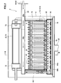
- FIG. 1 is an overall configuration diagram showing a solid oxide fuel cell (SOFC) according to an embodiment of the present invention.
- 1 is a front sectional view showing a solid oxide fuel cell (SOFC) fuel cell module according to an embodiment of the present invention.
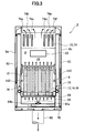
- FIG. 3 is a cross-sectional view taken along line III-III in FIG. 2.
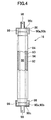
- 1 is a partial cross-sectional view showing a fuel cell unit of a solid oxide fuel cell (SOFC) according to an embodiment of the present invention.
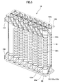
- 1 is a perspective view showing a fuel cell stack of a solid oxide fuel cell (SOFC) according to an embodiment of the present invention.
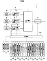
- 1 is a block diagram illustrating a solid oxide fuel cell (SOFC) according to an embodiment of the present invention.
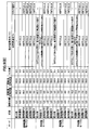
- the fuel flow rate, the reforming air flow rate, the power generation air flow rate, the water flow rate, and the reforming in each operation state of the normal startup and restarting operations of the solid oxide fuel cell (SOFC) according to an embodiment of the present invention is a data table which shows the transition temperature conditions of a mass device and a stack. It is a flowchart which shows the 1st example of the restart control flow for performing restart in the solid oxide fuel cell (SOFC) by one Embodiment of this invention.
- FIG. 10 is a time chart showing the operation when the restart is executed based on the first example of the restart control flow of the solid oxide fuel cell (SOFC) according to the embodiment of the present invention shown in FIG. It is the figure compared with the time chart which shows.
- FIG. 12 is a time chart showing the operation when the restart is executed based on the second example of the restart control flow of the solid oxide fuel cell (SOFC) according to the embodiment of the present invention. It is the figure compared with the time chart which shows. It is a flowchart which shows the 3rd example of the restart control flow for performing restart in the solid oxide fuel cell (SOFC) by one Embodiment of this invention.
- FIG. 14 is a time chart showing the operation when the restart is executed based on the third example of the restart control flow of the solid oxide fuel cell (SOFC) according to the embodiment of the present invention.
- FIG. 16 is a time chart showing the operation when the restart is executed based on the fourth example of the restart control flow of the solid oxide fuel cell (SOFC) according to the embodiment of the present invention. It is the figure compared with the time chart which shows. It is a flowchart which shows the 5th example of the restart control flow for performing restart in the solid oxide fuel cell (SOFC) by one Embodiment of this invention.
- FIG. 16 is a time chart showing the operation when the restart is executed based on the fourth example of the restart control flow of the solid oxide fuel cell (SOFC) according to the embodiment of the present invention. It is the figure compared with the time chart which shows. It is a flowchart which shows the 5th example of the restart control flow for performing restart in the solid oxide fuel cell (SOFC) by one Embodiment of this invention.
- FIG. 18 is a time chart showing the operation when the restart is executed based on the fifth example of the restart control flow of the solid oxide fuel cell (SOFC) according to the embodiment of the present invention. It is the figure compared with the time chart which shows.
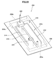
- FIG. 5 is a front cross-sectional view showing a solid oxide fuel cell (SOFC) fuel cell module according to another embodiment of the present invention. It is sectional drawing along the XXI-XXI line of FIG. It is the perspective view which looked at the cell assembly support unit of the fuel cell module of the solid oxide fuel cell (SOFC) by other embodiment of the present invention from the slanting upper part.
- SOFC solid oxide fuel cell
- FIG. 1 is an overall configuration diagram showing a solid oxide fuel cell (SOFC) according to an embodiment of the present invention.
- a solid oxide fuel cell (SOFC) 1 according to an embodiment of the present invention includes a fuel cell module 2 and an auxiliary unit 4.
- the fuel cell module 2 includes a housing 6, and a sealed space 8 is formed inside the housing 6 via a heat insulating material (not shown, but the heat insulating material is not an essential component and may not be necessary). Is formed. In addition, you may make it not provide a heat insulating material.
- a fuel cell assembly 12 that performs a power generation reaction with fuel gas and an oxidant (air) is disposed in a power generation chamber 10 that is a lower portion of the sealed space 8.
- the fuel cell assembly 12 includes ten fuel cell stacks 14 (see FIG. 5), and the fuel cell stack 14 includes 16 fuel cell unit 16 (see FIG. 4). Yes.
- the fuel cell assembly 12 has 160 fuel cell units 16, and all of these fuel cell units 16 are connected in series.
- a combustion chamber 18 is formed above the above-described power generation chamber 10 in the sealed space 8 of the fuel cell module 2.
- this combustion chamber 18 the remaining fuel gas that has not been used for the power generation reaction and the remaining oxidant (air) ) And combusted to generate exhaust gas.
- a reformer 20 for reforming the fuel gas is disposed above the combustion chamber 18, and the reformer 20 is heated to a temperature at which a reforming reaction can be performed by the combustion heat of the residual gas.
- an air heat exchanger 22 for receiving combustion heat and heating air is disposed above the reformer 20.
- the auxiliary unit 4 stores a pure water tank 26 that stores water from a water supply source 24 such as tap water and uses the filter to obtain pure water, and a water flow rate that adjusts the flow rate of the water supplied from the water storage tank.
- An adjustment unit 28 (such as a “water pump” driven by a motor) is provided.
- the auxiliary unit 4 also includes a gas shut-off valve 32 that shuts off the fuel gas supplied from a fuel supply source 30 such as city gas, a desulfurizer 36 for removing sulfur from the fuel gas, and a flow rate of the fuel gas.
- a fuel flow rate adjusting unit 38 (such as a “fuel pump” driven by a motor) is provided.
- the auxiliary unit 4 includes an electromagnetic valve 42 that shuts off air that is an oxidant supplied from the air supply source 40, a reforming air flow rate adjusting unit 44 that adjusts the flow rate of air, and a power generation air flow rate adjusting unit. 45 (such as an “air blower” driven by a motor), a first heater 46 for heating the reforming air supplied to the reformer 20, and a second for heating the power generating air supplied to the power generation chamber And a heater 48.
- the first heater 46 and the second heater 48 are provided in order to efficiently raise the temperature at startup, but may be omitted.
- a hot water production apparatus 50 to which exhaust gas is supplied is connected to the fuel cell module 2.
- the hot water production apparatus 50 is supplied with tap water from the water supply source 24, and the tap water is heated by the heat of the exhaust gas and supplied to a hot water storage tank of an external hot water heater (not shown).
- the fuel cell module 2 is provided with a control box 52 for controlling the amount of fuel gas supplied and the like. Furthermore, the fuel cell module 2 is connected to an inverter 54 that is a power extraction unit (power conversion unit) for supplying the power generated by the fuel cell module to the outside.
- FIG. 2 is a side sectional view showing a solid oxide fuel cell (SOFC) fuel cell module according to an embodiment of the present invention
- FIG. 3 is a sectional view taken along line III-III in FIG.
- the fuel cell assembly 12, the reformer 20, and the air heat exchange are sequentially performed from below.
- a vessel 22 is arranged.
- the reformer 20 is provided with a pure water introduction pipe 60 for introducing pure water and a reformed gas introduction pipe 62 for introducing reformed fuel gas and reforming air to the upstream end side thereof.
- a pure water introduction pipe 60 for introducing pure water
- a reformed gas introduction pipe 62 for introducing reformed fuel gas and reforming air to the upstream end side thereof.
- an evaporation unit 20a and a reforming unit 20b are formed in order from the upstream side, and the reforming unit 20b is filled with a reforming catalyst.
- the fuel gas and air mixed with the steam (pure water) introduced into the reformer 20 are reformed by the reforming catalyst filled in the reformer 20.
- the reforming catalyst a catalyst obtained by imparting nickel to the alumina sphere surface or a catalyst obtained by imparting ruthenium to the alumina sphere surface is appropriately used.
- a fuel gas supply pipe 64 is connected to the downstream end side of the reformer 20, and the fuel gas supply pipe 64 extends downward and further in an manifold 66 formed below the fuel cell assembly 12. It extends horizontally.
- a plurality of fuel supply holes 64 b are formed in the lower surface of the horizontal portion 64 a of the fuel gas supply pipe 64, and the reformed fuel gas is supplied into the manifold 66 from the fuel supply holes 64 b.
- a lower support plate 68 having a through hole for supporting the fuel cell stack 14 described above is attached above the manifold 66, and the fuel gas in the manifold 66 flows into the fuel cell unit 16. Supplied.
- the air heat exchanger 22 includes an air aggregation chamber 70 on the upstream side and two air distribution chambers 72 on the downstream side.
- the air aggregation chamber 70 and the air distribution chamber 72 include six air flow path tubes 74. Connected by.
- three air flow path pipes 74 form a set (74a, 74b, 74c, 74d, 74e, 74f), and the air in the air collecting chamber 70 is in each set. It flows into each air distribution chamber 72 from the air flow path pipe 74.
- the air flowing through the six air flow path pipes 74 of the air heat exchanger 22 is preheated by exhaust gas that burns and rises in the combustion chamber 18.
- An air introduction pipe 76 is connected to each of the air distribution chambers 72, the air introduction pipe 76 extends downward, and the lower end side communicates with the lower space of the power generation chamber 10, and the air that has been preheated in the power generation chamber 10. Is introduced.
- an exhaust gas chamber 78 is formed below the manifold 66. Further, as shown in FIG. 3, an exhaust gas passage 80 extending in the vertical direction is formed inside the front surface 6 a and the rear surface 6 b which are surfaces along the longitudinal direction of the housing 6, and the upper end side of the exhaust gas passage 80 is formed. Is in communication with the space in which the air heat exchanger 22 is disposed, and the lower end side is in communication with the exhaust gas chamber 78. Further, an exhaust gas discharge pipe 82 is connected to substantially the center of the lower surface of the exhaust gas chamber 78, and the downstream end of the exhaust gas discharge pipe 82 is connected to the above-described hot water producing apparatus 50 shown in FIG. As shown in FIG. 2, an ignition device 83 for starting combustion of fuel gas and air is provided in the combustion chamber 18.
- FIG. 4 is a partial cross-sectional view showing a fuel cell unit of a solid oxide fuel cell (SOFC) according to an embodiment of the present invention.
- the fuel cell unit 16 includes a fuel cell 84 and inner electrode terminals 86 respectively connected to the vertical ends of the fuel cell 84.
- the fuel cell 84 is a tubular structure that extends in the vertical direction, and includes a cylindrical inner electrode layer 90 that forms a fuel gas flow path 88 therein, a cylindrical outer electrode layer 92, an inner electrode layer 90, and an outer side.
- An electrolyte layer 94 is provided between the electrode layer 92 and the electrode layer 92.
- the inner electrode layer 90 is a fuel electrode through which fuel gas passes and becomes a ( ⁇ ) electrode, while the outer electrode layer 92 is an air electrode in contact with air and becomes a (+) electrode.
- the upper portion 90 a of the inner electrode layer 90 includes an outer peripheral surface 90 b and an upper end surface 90 c exposed to the electrolyte layer 94 and the outer electrode layer 92.
- the inner electrode terminal 86 is connected to the outer peripheral surface 90b of the inner electrode layer 90 through a conductive sealing material 96, and is further in direct contact with the upper end surface 90c of the inner electrode layer 90, thereby Electrically connected.
- a fuel gas passage 98 communicating with the fuel gas passage 88 of the inner electrode layer 90 is formed at the center of the inner electrode terminal 86.
- the inner electrode layer 90 includes, for example, a mixture of Ni and zirconia doped with at least one selected from rare earth elements such as Ca, Y, and Sc, and Ni and ceria doped with at least one selected from rare earth elements.
- the mixture is formed of at least one of Ni and a mixture of lanthanum garade doped with at least one selected from Sr, Mg, Co, Fe, and Cu.
- the electrolyte layer 94 is, for example, zirconia doped with at least one selected from rare earth elements such as Y and Sc, ceria doped with at least one selected from rare earth elements, lanthanum gallate doped with at least one selected from Sr and Mg, Formed from at least one of the following.
- the outer electrode layer 92 includes, for example, lanthanum manganite doped with at least one selected from Sr and Ca, lanthanum ferrite doped with at least one selected from Sr, Co, Ni and Cu, Sr, Fe, Ni and Cu. It is formed from at least one of lanthanum cobaltite doped with at least one selected from the group consisting of silver and silver.
- FIG. 5 is a perspective view showing a fuel cell stack of a solid oxide fuel cell (SOFC) according to an embodiment of the present invention.
- the fuel cell stack 14 includes 16 fuel cell units 16, and the lower end side and the upper end side of these fuel cell units 16 are a ceramic lower support plate 68 and an upper side, respectively. It is supported by the support plate 100.
- the lower support plate 68 and the upper support plate 100 are formed with through holes 68a and 100a through which the inner electrode terminal 86 can pass.
- the current collector 102 includes a fuel electrode connection portion 102a that is electrically connected to an inner electrode terminal 86 attached to the inner electrode layer 90 that is a fuel electrode, and an entire outer peripheral surface of the outer electrode layer 92 that is an air electrode. And an air electrode connecting portion 102b electrically connected to each other.
- the air electrode connecting portion 102b is formed of a vertical portion 102c extending in the vertical direction on the surface of the outer electrode layer 92 and a plurality of horizontal portions 102d extending in a horizontal direction along the surface of the outer electrode layer 92 from the vertical portion 102c. Has been.
- the fuel electrode connecting portion 102a is linearly directed obliquely upward or obliquely downward from the vertical portion 102c of the air electrode connecting portion 102b toward the inner electrode terminal 86 positioned in the vertical direction of the fuel cell unit 16. It extends.
- the inner electrode terminals 86 at the upper end and the lower end of the two fuel cell units 16 located at the ends of the fuel cell stack 14 are external terminals, respectively. 104 is connected. These external terminals 104 are connected to the external terminals 104 (not shown) of the fuel cell unit 16 at the end of the adjacent fuel cell stack 14, and as described above, the 160 fuel cell units 16 Everything is connected in series.
- FIG. 6 is a block diagram illustrating a solid oxide fuel cell (SOFC) according to an embodiment of the present invention.
- the solid oxide fuel cell 1 includes a control unit 110, and the control unit 110 includes operation buttons such as “ON” and “OFF” for operation by the user.
- a device 112 a display device 114 for displaying various data such as a power generation output value (wattage), and a notification device 116 for issuing an alarm (warning) in an abnormal state are connected.
- the notification device 116 may be connected to a remote management center and notify the management center of an abnormal state.
- the combustible gas detection sensor 120 is for detecting a gas leak, and is attached to the fuel cell module 2 and the auxiliary unit 4.
- the CO detection sensor 122 detects whether or not CO in the exhaust gas originally discharged to the outside through the exhaust gas passage 80 or the like leaks to an external housing (not shown) that covers the fuel cell module 2 and the auxiliary unit 4. Is to do.
- the hot water storage state detection sensor 124 is for detecting the temperature and amount of hot water in a water heater (not shown).
- the power state detection sensor 126 is for detecting the current and voltage of the inverter 54 and the distribution board (not shown).
- the power generation air flow rate detection sensor 128 is for detecting the flow rate of power generation air supplied to the power generation chamber 10.
- the reforming air flow sensor 130 is for detecting the flow rate of the reforming air supplied to the reformer 20.
- the fuel flow sensor 132 is for detecting the flow rate of the fuel gas supplied to the reformer 20.
- the water flow rate sensor 134 is for detecting the flow rate of pure water (steam) supplied to the reformer 20.
- the water level sensor 136 is for detecting the water level of the pure water tank 26.
- the pressure sensor 138 is for detecting the pressure on the upstream side outside the reformer 20.
- the exhaust temperature sensor 140 is for detecting the temperature of the exhaust gas flowing into the hot water production apparatus 50.
- the power generation chamber temperature sensor 142 is provided on the front side and the back side in the vicinity of the fuel cell assembly 12, and detects the temperature in the vicinity of the fuel cell stack 14 to thereby detect the fuel cell stack. 14 (ie, the fuel cell 84 itself) is estimated.
- the combustion chamber temperature sensor 144 is for detecting the temperature of the combustion chamber 18.
- the exhaust gas chamber temperature sensor 146 is for detecting the temperature of the exhaust gas in the exhaust gas chamber 78.
- the reformer temperature sensor 148 is for detecting the temperature of the reformer 20, and calculates the temperature of the reformer 20 from the inlet temperature and the outlet temperature of the reformer 20.
- the outside air temperature sensor 150 is for detecting the temperature of the outside air when the solid oxide fuel cell (SOFC) is disposed outdoors. Further, a sensor for measuring the humidity or the like of the outside air may be provided.
- SOFC solid oxide fuel cell
- Signals from these sensors are sent to the control unit 110, and the control unit 110, based on data based on these signals, the water flow rate adjustment unit 28, the fuel flow rate adjustment unit 38, the reforming air flow rate adjustment unit 44, A control signal is sent to the power generation air flow rate adjusting unit 45 to control each flow rate in these units. Further, the control unit 110 sends a control signal to the inverter 54 to control the power supply amount.
- FIG. 7 is a time chart showing the operation at the time of startup of the solid oxide fuel cell (SOFC) according to one embodiment of the present invention.
- reforming air is supplied from the reforming air flow rate adjustment unit 44 to the reformer 20 of the fuel cell module 2 via the first heater 46.
- the power generation air is supplied from the power generation air flow rate adjustment unit 45 to the air heat exchanger 22 of the fuel cell module 2 via the second heater 48, and this power generation air is supplied to the power generation chamber 10 and the combustion chamber.
- the fuel gas is also supplied from the fuel flow rate adjustment unit 38, and the fuel gas mixed with the reforming air passes through the reformer 20, the fuel cell stack 14, and the fuel cell unit 16, and It reaches the combustion chamber 18.
- the ignition device 83 is ignited to burn the fuel gas and air (reforming air and power generation air) in the combustion chamber 18.
- Exhaust gas is generated by the combustion of the fuel gas and air, and the power generation chamber 10 is warmed by the exhaust gas, and when the exhaust gas rises in the sealed space 8 of the fuel cell module 2, The fuel gas containing the reforming air is warmed, and the power generation air in the air heat exchanger 22 is also warmed.
- the fuel gas mixed with the reforming air is supplied to the reformer 20 by the fuel flow rate adjusting unit 38 and the reforming air flow rate adjusting unit 44.
- the heated fuel gas is supplied to the lower side of the fuel cell stack 14 through the fuel gas supply pipe 64, whereby the fuel cell stack 14 is heated from below, and the combustion chamber 18 also has the fuel gas and air.
- the fuel cell stack 14 is also heated from above, and as a result, the fuel cell stack 14 can be heated substantially uniformly in the vertical direction. Even if the partial oxidation reforming reaction POX proceeds, the combustion reaction between the fuel gas and air continues in the combustion chamber 18.
- the reformer temperature sensor 148 detects that the reformer 20 has reached a predetermined temperature (for example, 600 ° C.) after the partial oxidation reforming reaction POX is started, the water flow rate adjustment unit 28 and the fuel flow rate adjustment unit 38 are detected.
- the reforming air flow rate adjusting unit 44 supplies a gas in which fuel gas, reforming air, and water vapor are mixed in advance to the reformer 20.
- an autothermal reforming reaction ATR in which the partial oxidation reforming reaction POX described above and a steam reforming reaction SR described later are used proceeds. Since the autothermal reforming reaction ATR is thermally balanced internally, the reaction proceeds in the reformer 20 in a thermally independent state.
- the reformer temperature sensor 146 detects that the reformer 20 has reached a predetermined temperature (for example, 700 ° C.) after the start of the autothermal reforming reaction ATR shown in Formula (2), the reforming air flow rate The supply of reforming air by the adjustment unit 44 is stopped, and the supply of water vapor by the water flow rate adjustment unit 28 is increased. As a result, the reformer 20 is supplied with a gas that does not contain air and contains only fuel gas and water vapor, and the steam reforming reaction SR of formula (3) proceeds in the reformer 20.
- a predetermined temperature for example, 700 ° C.
- this steam reforming reaction SR is an endothermic reaction, the reaction proceeds while maintaining a heat balance with the combustion heat from the combustion chamber 18. At this stage, since the fuel cell module 2 is in the final stage of start-up, the power generation chamber 10 is heated to a sufficiently high temperature. Therefore, even if the endothermic reaction proceeds, the power generation chamber 10 is greatly reduced in temperature. There is nothing. Even if the steam reforming reaction SR proceeds, the combustion reaction continues in the combustion chamber 18.
- the partial oxidation reforming reaction POX, the autothermal reforming reaction ATR, and the steam reforming reaction SR proceed in sequence, so that the inside of the power generation chamber 10 The temperature gradually increases.
- the circuit including the fuel cell module 2 is closed, and the fuel cell Power generation by the module 2 is started, so that a current flows in the circuit. Due to the power generation of the fuel cell module 2, the fuel cell 84 itself also generates heat, and the temperature of the fuel cell 84 also rises.
- the rated rated temperature at which the fuel cell module 2 is operated becomes, for example, 600 ° C. to 800 ° C.
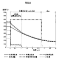
- FIG. 8 is a time chart showing the operation when the solid oxide fuel cell (SOFC) is stopped according to this embodiment.
- the fuel flow rate adjustment unit 38 and the water flow rate adjustment unit 28 are operated to supply fuel gas and water vapor to the reformer 20. Reduce the amount.
- the amount of fuel gas and water vapor supplied to the reformer 20 is reduced, and at the same time, the fuel cell module for generating air by the reforming air flow rate adjusting unit 44
- the supply amount into 2 is increased, the fuel cell assembly 12 and the reformer 20 are cooled by air, and these temperatures are lowered.
- the temperature of the power generation chamber decreases to a predetermined temperature, for example, 400 ° C.
- the supply of fuel gas and steam to the reformer 20 is stopped, and the steam reforming reaction SR of the reformer 20 is ended.
- This supply of power generation air continues until the temperature of the reformer 20 decreases to a predetermined temperature, for example, 200 ° C., and when this temperature is reached, the power generation air from the power generation air flow rate adjustment unit 45 is supplied. Stop supplying.
- the steam reforming reaction SR by the reformer 20 and the cooling by the power generation air are used in combination.
- the operation of the fuel cell module can be stopped.
- 9A and 9B show the fuel flow rate, the reforming air flow rate, the power generation in the respective operation states of the solid oxide fuel cell (SOFC) according to the present embodiment during normal startup and restart operation. It is a data table which shows the transition temperature conditions of the air flow rate for water, water flow rate, and a reformer and a stack
- the solid oxide fuel cell (SOFC) according to the present embodiment is the same as the solid oxide fuel cell (SOFC) according to the present embodiment shown in FIG.
- the normal operation mode based on the control mode hereinafter referred to as “normal start mode 1” that executes the same operation as the normal start mode of the operation and the normal start mode different from the normal start mode 1 “Normal startup mode 2” is disclosed as a modified example for executing startup.
- the solid oxide fuel cell (SOFC) according to the present embodiment starts operation (so-called “restart” in a state in which the solid oxide fuel cell (SOFC) according to the present embodiment shown in FIG. 8 is stopped. ))
- restart modes 1 to 5 are disclosed.
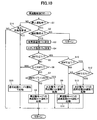
- FIG. 10 is a flowchart showing a first example of restart control flow (restart control flow 1) for restarting a solid oxide fuel cell (SOFC) according to an embodiment of the present invention.
- S indicates each step. First, in S1, it is determined whether or not the fuel cell module 2 is in a stop operation. If the fuel cell module 2 is in a stop operation, the process proceeds to S2 and it is determined whether or not a restart is requested.
- the process proceeds to S3, where the reforming which is part of the reforming state temperature detecting means for detecting the reforming state temperature for changing the reforming state by the reformer 20 is performed.
- the process proceeds to S4, and the reformed state temperature for changing the reformed state by the reformer 20 is detected.
- the stack temperature Ts which is the temperature in the vicinity of the fuel cell stack 14 (that is, the fuel cell 84 itself), is measured by the power generation chamber temperature sensor 142 which is a part of the reforming state temperature detecting means.
- it progresses to S5 and it is determined whether the reformer temperature Tr is 400 degreeC or more.
- the process proceeds to S6, and it is determined whether or not the reformer temperature Tr is less than 200 ° C. If it is determined in S6 that the reformer temperature Tr is not less than 200 ° C., that is, the reformer temperature Tr is 200 ° C. or more and less than 400 ° C., the process proceeds to S7, where the reformer temperature Tr is 200 ° C. or more. It is determined whether the temperature is less than 250 ° C.
- the process proceeds to S12, in which it is determined whether or not the stack temperature Ts measured by the power generation chamber temperature sensor 142 is 600 ° C. or higher. To do. If it is determined in S12 that the stack temperature Ts is 600 ° C. or higher, the process proceeds to S13, and “normal start SR” is executed by “restart mode 1” in the data table shown in FIG. 9A. On the other hand, if it is determined in S12 that the stack temperature Ts is not 600 ° C. or higher, that is, the reformer temperature Tr is 600 ° C. or higher, but the stack temperature Ts is lower than 600 ° C., the process proceeds to S11. Then, the “normal activation ATR” by the “reactivation mode 1” in the data table shown in FIG. 9A is executed.
- S1 it is determined whether or not the fuel cell module 2 is in a stop operation. If the fuel cell module 2 is not in a stop operation, the process proceeds to S14, in which it is determined whether or not it is a restart request based on misfire during startup. To do. If it is determined in S14 that there is a request for restart based on misfire, and if it is determined in S6 that the reformer temperature Tr is less than 200 ° C., the value of the temperature sensor may be apparently high. Since not all of the fuel cell modules have been in a high temperature state for a long time, there is no situation in which heat is uniformly stored, so there is no situation in which restart control based on residual heat can be performed, so the process proceeds to S15, and FIG. 9 (A) Reactivation is executed based on “normal activation mode 1” in the data table shown in FIG.
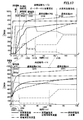
- FIG. 11 is a time chart showing the operation when the restart is executed based on the first example of the restart control flow of the solid oxide fuel cell (SOFC) according to the present embodiment shown in FIG. It is the figure compared with the time chart which shows operation
- the time chart in the upper part of FIG. 11 is a time chart showing the normal startup operation of the solid oxide fuel cell (SOFC) when “normal startup mode 1” in the data table shown in FIG. 9A is executed.
- 11 is a time chart showing the restart operation of the solid oxide fuel cell (SOFC) when “restart mode 1” in the data table shown in FIG. 9A is executed. It is a chart.
- restart flow 1 the description of the restart operation based on the first example (restart flow 1) of the restart control flow of the solid oxide fuel cell (SOFC) according to the present embodiment below is shown in FIG.
- start flow 1 the description of the restart operation based on the first example (restart flow 1) of the restart control flow of the solid oxide fuel cell (SOFC) according to the present embodiment below is shown in FIG.
- FIG. 11 About the operation at the time of restart by the “restart mode 1” of the solid oxide fuel cell (SOFC) of this embodiment shown in FIG. 11 while referring to the data table regarding “normal start mode 1” and “restart mode 1” The operation will be described in comparison with the operation at the time of normal activation in “normal activation mode 1”.
- the column “state” of “normal start mode 1” shown in FIG. 9A represents each operation state at the time of normal start from the upper stage toward the lower stage, and each operation state is as follows. They are distinguished by being abbreviated as “at the time of ignition”, “combustion operation”, “normal start POX”, “normal start ATR”, and “normal start SR”. Incidentally, with respect to time t, which is the horizontal axis of the time chart of “normal start mode 1” in FIG.
- the time of “ignition” is set to t1, and “normal start POX”, “normal start ATR”, and “ The times when shifting to the “normal startup SR” are t2, t3, and t4, respectively, the temperature of the reformer 20 detected by the reformer temperature sensor 148 at the time t is Tr (t), and at the time t.
- the stack temperature measured by the power generation chamber temperature sensor 142 be Ts (t).
- Tr (t) the stack temperature Ts measured by the power generation chamber temperature sensor 142 is in the temperature range of 250 ° C. or higher and lower than 600 ° C. (250 ° C.
- the temperature Tr (t) of the reformer 20 detected by the reformer temperature sensor 148 is a predetermined steady temperature Tr (
- the start is controlled in the control band for executing SR (hereinafter referred to as “normal start mode SR control band B4”). ing.
- the column “fuel flow rate” shown in FIGS. 9A and 9B indicates the fuel gas supplied to the reformer 20 from the fuel flow rate adjustment unit 38 which is the fuel gas supply means of the auxiliary unit 4.
- the flow rate [L / min] is shown.
- the column “reforming air flow rate” shown in FIGS. 9A and 9B shows a reforming air flow rate adjusting unit which is an oxidant gas supply means of the auxiliary unit 4 in each operation state. 44 shows the flow rate [L / min] of the oxidizing gas (reforming air) supplied to the reformer 20 from the first heater 46 as the oxidizing gas heating means.
- the column of “power generation air flow rate” shown in FIG. 9A and FIG. 9B indicates that power is generated from the power generation air flow rate adjustment unit 45 of the auxiliary unit 4 via the second heater 48 in each operation state.
- the flow rate [L / min] of the power generation air supplied to the chamber 10 is shown.
- the column “water flow rate” shown in FIGS. 9A and 9B is a water supply means that generates pure water of the auxiliary unit 4 and supplies it to the reformer 20 in each operation state.
- the flow rate [cc / min] of pure water supplied from a certain water flow rate adjustment unit 28 to the reformer 20 is shown.
- “reformer temperature” of “transition temperature condition” in the “combustion operation” state column of “normal start mode 1” is indicated as “300 ° C. or higher”. That is, when the temperature Tr (t) of the reformer 20 detected by the reformer temperature sensor 148 becomes 300 ° C. or higher, the operation state of “combustion operation” is shifted to the operation state of “normal start POX”. Means.
- “reformer temperature” of “transition temperature condition” in the “normal start POX” status column of “normal start mode 1” is indicated as “600 ° C. or higher”, and “stack temperature” is “250”.
- the temperature Tr (t) of the reformer 20 detected by the reformer temperature sensor 148 is 600 ° C. or more, and this is the stack measured by the power generation chamber temperature sensor 142. When the temperature Ts becomes 250 ° C. or higher, it means that the operation state of “normal start POX” is shifted to the operation state of “normal start ATR”.
- the column “state” of “restart mode 1” shown in FIG. 9A represents each operation state at the time of restart from the upper stage toward the lower stage in time series.
- time t which is the horizontal axis of the time chart of “restart mode 1” in FIG.
- the times when shifting to “ATR” and “normal activation SR” are t12, t13a, t13b, and t14, respectively.
- the operation state of “at the time of ignition” in “restart mode 1” shown in FIG. 9A is the reformer temperature sensor 148 when the restart is requested during the stop operation of the fuel cell module 2.
- Is a predetermined temperature Tr that is lower than the POX start temperature Tr (t2) ( 300 ° C.) of the normal startup mode POX control band B2 of the “normal startup mode 1” described above.
- the ignition device 83 is ignited, and immediately after the fuel gas is ignited, the “restart mode 1” “restart” The operation state is shifted to “starting POX” (see S7 and S8 in FIG. 10).
- starting POX see S7 and S8 in FIG. 10.
- the “fuel flow rate” at “ignition” in “restart mode 1” shown in FIG. 9A is 5.5 [L / min], and “at ignition” in “normal start mode 1”. It is less than the “fuel flow rate” (6.0 [L / min]).
- the operation state of “restart POX” executed in the restart mode POX control band B12 of “restart mode 1” is “normal start” executed in the normal start mode POX control band B2 of “normal start mode 1”.
- the operation state is different from “POX”.
- the temperature band in which “restart POX” is executed in the restart mode POX control band B12 of “restart mode 1” is “normal start mode”.
- 1 normal activation mode POX control band B2“ normal activation POX ”is executed Normal temperature POX temperature band W2 (300 ° C. ⁇ Tr (t) ⁇ 600 ° C., Ts ⁇ 250 ° C.) (200 ° C. ⁇ Tr (t) ⁇ 250 ° C.).
- the “fuel flow rate” in the operation state of “restart POX” in “restart mode 1” is 5.5 [L / min]
- the “fuel flow rate” (5.0 [L / min]) in the “normal startup POX” operating state of “normal startup mode 1” is smaller than the “fuel flow rate” (6.0 [L / min]) in min]).
- the “reforming air flow rate” in the operation state of “restart POX” in “restart mode 1” is 17.0 [L / min], and “normal start POX” in “normal start mode 1”. It is less than the “reforming air flow rate” (18.0 [L / min]) in the operating state.
- the operation state “restart ATR” of “restart mode 1” shown in S8 of FIG. 9A and FIG. 10 is “normal start POX” and “normal start ATR” of “normal start mode 1”.
- the restart is controlled in a control band (hereinafter referred to as “restart mode ATR control band B13a”) in which ATR is executed differently. More specifically, the temperature band in which “restart ATR” is executed in the restart mode ATR control band B13a of “restart mode 1” (hereinafter referred to as “restart ATR temperature band W13a”) is “restart mode”.
- 1 restart POX temperature zone W12 (200 ° C. ⁇ Tr ⁇ 250 ° C.) higher than 250 ° C. and less than 400 ° C. (250 ° C. ⁇ Tr ⁇ 400 ° C., Ts ⁇ 400 ° C.) Yes.
- restart mode ATR control band B13a of “restart mode 1” particularly, the restart ATR temperature band W13a (250 ° C. ⁇ Tr ⁇ 400 ° C., Ts ⁇ 400 ° C.) of “restart mode 1” is “ Despite overlapping with a part of the normal startup POX temperature band W2 (300 ° C. ⁇ Tr (t) ⁇ 600 ° C., Ts ⁇ 250 ° C.) of the “normal startup mode 1”, “Activation POX” is not executed.
- the “fuel flow rate” in the operation state of “restart ATR” in “restart mode 1” is 5.0 [L / min], and in the operation state of “normal start POX” in “normal start mode 1”. Equal to “fuel flow rate” (5.0 [L / min]), more than “fuel flow rate” (4.0 [L / min]) in the “normal startup ATR” operating state of “normal startup mode 1” It has become.
- the “reforming air flow rate” in the operation state of “restart ATR” in “restart mode 1” is 8.0 [L / min], and “normal start POX” in “normal start mode 1”.
- the “reforming air flow rate” (18.0 [L / min]) in the operating state is less than the “reforming air flow rate” (18.0 [L / min]) and the “normal starting ATR” operating state in the “normal starting mode 1” (4. 0 [L / min]).
- water flow rate in the operation state of “restart ATR” in “restart mode 1” is 2.0 [cc / min], and in the operation state of “normal start ATR” in “normal start mode 1”. It is less than “water flow rate” (3.0 [L / min]).
- restart mode ATR control band B13b a control band that executes the same ATR as the “normal start ATR” in “normal start mode 1”.
- the operation state “normal start SR” of “restart mode 1” shown in S13 of FIG. 9A and FIG. 10 is “transition temperature condition” of “normal start SR” of “normal start mode 1”.
- the restart is controlled in the control band (hereinafter referred to as “restart mode SR control band B14”) that executes the same SR as the “normal start SR” of “normal start mode 1” under the same conditions as above.
- restart mode 1 restart mode a control band for executing “normal start ATR” from “restart POX” in “restart mode 1” described above through “restart ATR” (hereinafter referred to as “restart mode 1 restart mode”). Focusing on “control band”), the restart by the restart mode control band is compared with the normal start by “normal start mode 1”. In the restart mode control zone of “restart mode 1”, the temperature Tr (t) of the reformer 20 is set to the normal startup POX temperature zone W2 (300) of “normal startup mode 1” by stopping the operation of the fuel cell module 2.
- restart ATR temperature band W13a 250 ° C. ⁇ Tr ⁇ 400 ° C., Ts ⁇ 400 ° C.
- this restart ATR temperature band W13a or W13b 400 ° C. ⁇ Tr ⁇ 600 ° C., 400 Even if the temperature is within the range of C.degree..ltoreq.Ts ⁇ 600.degree. C.), it is unlikely that residual heat remaining in the fuel cell stack 14 or the reformer 20 can be used.
- the “restart ATR” and “normal start ATR” in the band are prohibited and are executed from the “combustion operation” after the ignition of the “normal start mode 1” (see S14 and S15 in FIG. 10).
- the time t13b when shifting from “restart ATR” in “restart mode 1” to “normal start ATR” is from “normal start POX” in “normal start mode 1” to “ The time is shorter than the time t3 when shifting to the “normal activation ATR”.
- the “normal start mode 1” “normal start ATR” shifts to the “normal start SR”. This is a time shorter than the time t4 when starting, and the activation time due to restart is shorter than the activation time due to normal activation.
- the temperature Tr (t) of the reformer 20 is stopped by stopping the operation of the fuel cell module 2. Decreases from the high temperature side of the temperature range corresponding to the normal startup POX temperature band W2 (300 ° C. ⁇ Tr (t) ⁇ 600 ° C., Ts ⁇ 250 ° C.) of the “normal startup mode 1”.
- the temperature Tr (t) of the reformer 20 is within the normal startup POX temperature zone W2 by actively using the remaining heat remaining in the fuel cell stack 14 and the reformer 20 Even in such a case, it is possible to skip execution of “normal start POX” in the normal start mode POX control band B2 in “normal start mode 1”. Then, in place of the skipped “normal start POX” of “normal start mode 1”, in the restart ATR temperature band W13a of “restart mode 1” (250 ° C.
- the “restart ATR” in which the “water flow rate” is smaller than the “normal start ATR” in the “normal start mode 1” can be executed, and the normal start ATR temperature band W13b (400 ° C. ⁇ Tr ⁇ 600 ° C., 400 ° C. ⁇ In Ts ⁇ 600 ° C., the normal activation mode ATR control band B3 by “normal activation mode 1” is expanded and “normal activation ATR” of “reactivation mode 1” identical to “normal activation ATR” of “normal activation mode 1” Can be executed.
- the oxidation of the fuel cell 84 is reduced.
- the burden on the fuel battery cell 84 due to the abnormally high temperature can be reduced, and the durability of the fuel battery cell 84 can be improved.
- “normal startup POX” in “normal startup mode 1” can be obtained by actively using the residual heat remaining in the fuel cell stack 14 and the reformer 20.
- “restart mode 1”, “restart POX”, “restart ATR”, “normal start ATR”, and “normal start SR” are executed sequentially from “when ignited” It is possible to speed up the transition from ignition to ATR and SR.
- the “normal start mode 1” is in a temperature range corresponding to the normal start POX temperature band W2 (300 ° C. ⁇ Tr (t) ⁇ 600 ° C., Ts ⁇ 250 ° C.) of the “normal start mode 1” at the time of restart.
- the reformer 20 starts from the “ignition” of “restart mode 1” at the time of restart.
- the “restart POX”, “restart ATR”, “normal start ATR”, and “normal start SR” are executed in sequence, so that the temperature of the fuel cell unit 16 does not decrease and is optimal. The temperature can be recovered stably in the state.
- the restart control according to the first example of the restart control flow in the solid oxide fuel cell (SOFC) of the present embodiment, it is executed before the transition to the “restart ATR” in the “restart mode 1”.
- the “restart POX” is lower than the normal start POX temperature band W2 (300 ° C. ⁇ Tr (t) ⁇ 600 ° C., Ts ⁇ 250 ° C.) in which “normal start POX” in “normal start mode 1” is executed.
- W2 300 ° C. ⁇ Tr (t) ⁇ 600 ° C., Ts ⁇ 250 ° C.
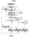
- FIG. 12 is a flowchart showing a second example of restart control flow (restart control flow 2) for restarting a solid oxide fuel cell (SOFC) according to an embodiment of the present invention.
- S indicates each step. First, in S101, it is determined whether or not the fuel cell module 2 is in a stop operation. If the fuel cell module 2 is in a stop operation, the process proceeds to S102 and it is determined whether or not a restart is requested.
- the process proceeds to S103, the temperature Tr of the reformer 20 is measured by the reformer temperature sensor 148, and then the process proceeds to S104.
- a stack temperature Ts that is a temperature in the vicinity of the stack 14 (that is, the fuel cell 84 itself) is measured.
- it progresses to S105 and it is determined whether the reformer temperature Tr (t) is 400 degreeC or more.
- the process proceeds to S106, and it is determined whether or not the reformer temperature Tr (t) is less than 200 ° C.
- S106 when it is determined that the reformer temperature Tr (t) is not less than 200 ° C., that is, the reformer temperature Tr (t) is 200 ° C. or more and less than 400 ° C., the process proceeds to S107, and FIG. "Restart ATR" is executed by "Restart mode 2" in the data table shown in A).
- the process proceeds to S108, and it is determined whether or not the reformer temperature Tr (t) is 600 ° C. or higher. . If it is determined in S108 that the reformer temperature Tr (t) is not 600 ° C. or higher, that is, the reformer temperature Tr (t) is 400 ° C. or higher and lower than 600 ° C., the process proceeds to S109, and FIG. “Normal activation ATR” is executed by “reactivation mode 2” in the data table shown in A).
- the process proceeds to S110, and it is determined whether or not the stack temperature Ts measured by the power generation chamber temperature sensor 142 is 600 ° C. or higher. To do.
- S110 when it is determined that the stack temperature Ts is 600 ° C. or higher, the process proceeds to S111, and “normal start SR” is executed by “restart mode 2” in the data table shown in FIG. 9A.
- the process proceeds to S109, and the “normal activation ATR” by the “reactivation mode 2” in the data table shown in FIG. 9A is executed.
- S101 it is determined whether or not the fuel cell module 2 is in a stop operation. If the fuel cell module 2 is not in a stop operation, the process proceeds to S112 and it is determined whether or not there is a request for restart based on misfire during startup. To do. If it is determined in S112 that there is a request for restart based on misfire, and if it is determined in S106 that the reformer temperature Tr (t) is lower than 200 ° C., the same as in the first embodiment, S113. Then, since the restart table cannot be used, the restart is executed according to “normal start mode 1” in the data table shown in FIG.
- FIG. 13 is a time chart showing the operation when the restart is executed based on the second example of the restart control flow of the solid oxide fuel cell (SOFC) according to the present embodiment shown in FIG. It is the figure compared with the time chart which shows operation
- the time chart in the upper part of FIG. 13 is a time chart showing the normal startup operation of the solid oxide fuel cell (SOFC) when “normal startup mode 1” in the data table shown in FIG. 9A is executed.
- the time chart at the bottom of FIG. 13 is a time showing the restart operation of the solid oxide fuel cell (SOFC) when “restart mode 2” in the data table shown in FIG. 9A is executed. It is a chart.
- restart flow 2 the restart control flow of the solid oxide fuel cell (SOFC) according to the present embodiment below is shown in FIG.
- the operation state of “in ignition” in “restart mode 2” shown in FIG. 9A is detected by the reformer temperature sensor 148 when a restart is requested during the stop operation of the fuel cell module 2.
- the predetermined temperature Tr (t21) where the temperature Tr (t) of the reformer 20 is lower than the POX start temperature Tr (t2) ( 300 ° C.) of the normal startup mode POX control zone B2 of the “normal startup mode 1” described above.
- the normal activation based on the “normal activation mode 1” is executed from the “combustion operation” after the ignition in the “normal activation mode 1” (FIG. 12). (See S106 and S113).
- restart ATR control band B23a a control band for executing ATR different from “restart ATR” in “restart mode 1”.
- restart ATR temperature band W23a “normal start A temperature band overlapping with a part of the normal startup POX temperature band W2 (300 ° C. ⁇ Tr ⁇ 600 ° C., Ts ⁇ 250 ° C.) in which “normal startup POX” is executed in the normal startup mode POX control band B2 of “mode 1” (200
- “normal start POX” of “normal start mode 1” is not executed in this overlapping temperature range.
- the “fuel flow rate” in the operation state of “restart ATR” in “restart mode 2” is 5.5 [L / min], and in the operation state of “normal start POX” in “normal start mode 1”. More than “fuel flow rate” (5.0 [L / min]) and “fuel flow rate” (4.0 [L / min]) in the “normal start-up ATR” operation state of “normal start-up mode 1” Yes.
- the “reforming air flow rate” in the operation state of “restart ATR” in “restart mode 2” is 12.0 [L / min], and “normal start POX” in “normal start mode 1”.
- the “reforming air flow rate” (18.0 [L / min]) in the operating state is less than the “reforming air flow rate” (18.0 [L / min]) and the “normal starting ATR” operating state in the “normal starting mode 1” (4. 0 [L / min]).
- the “water flow rate” in the “restart ATR” operation state in “restart mode 2” is 1.0 [cc / min], and the “normal start ATR” operation state in “normal start mode 1”. It is less than “water flow rate” (3.0 [L / min]).
- restart mode ATR control band B23b a control band that executes the same ATR as the “normal start ATR” of “normal start mode 1”.
- the operation state of “normal start SR” of “restart mode 2” shown in S111 of FIG. 9A and FIG. 12 is “transition temperature condition” of “normal start SR” of “normal start mode 1”.
- the restart is controlled in the control band (hereinafter referred to as “restart mode SR control band B24”) that executes the same SR as the “normal start SR” of “normal start mode 1” under the same conditions as above.
- restart mode 2 when restart is performed based on misfire at start-up, the temperature Tr (t) of the reformer 20 is set to “restart The restart ATR temperature band W23a (200 ° C. ⁇ Tr ⁇ 400 ° C., Ts ⁇ 400 ° C.) in the mode 2 ”is increased from the low temperature side, and this restart ATR temperature band W23a or W23b (400 ° C. ⁇ Tr ⁇ 600 ° C., 400 Even if the temperature is within the range of C.degree..ltoreq.Ts ⁇ 600.degree. C.), it is unlikely that the residual heat remaining in the fuel cell stack 14 or the reformer 20 can be used.
- the “restart ATR” and “normal start ATR” in the band are prohibited, and the “combustion operation” after the ignition in the “normal start mode 1” is executed (see S112 and S113 in FIG. 12).
- the time t23b when shifting from “restart ATR” in “restart mode 2” to “normal start ATR” is from “normal start POX” in “normal start mode 1” to “ The time is shorter than the time t3 when shifting to the “normal activation ATR”.
- the temperature Tr (t) of the reformer 20 due to the stop of the operation of the fuel cell module 2. Falls within the normal startup POX temperature band W2 by decreasing from the high temperature side corresponding to the normal startup POX temperature band W2 (300 ° C. ⁇ Tr ⁇ 600 ° C., Ts ⁇ 250 ° C.) of the “normal startup mode 1”. Sometimes, by actively utilizing the residual heat remaining in the fuel cell stack 14 and the reformer 20, even if the temperature Tr (t) of the reformer 20 is within the normal startup POX temperature zone W2.
- the “normal start ATR” of the “restart mode 1” that is the same as the “normal start ATR” of the “normal start mode 1” can be executed by expanding the band B3.
- the burden on the fuel cell 84 due to oxidation or abnormally high temperature can be reduced, and the durability of the fuel cell 84 can be improved.
- the reformer 20 starts from “ignition” in “restart mode 2” at the time of restart.
- the fuel cell unit 16 is stabilized in an optimal state without causing a temperature drop. The temperature can be recovered.
- FIG. 14 is a flowchart showing a third example of restart control flow (restart control flow 3) for restarting a solid oxide fuel cell (SOFC) according to an embodiment of the present invention.
- S indicates each step.
- S201 it is determined whether or not the fuel cell module 2 is in a stop operation. If the fuel cell module 2 is in a stop operation, the process proceeds to S202 and it is determined whether or not a restart is requested.
- the process proceeds to S203, the temperature Tr of the reformer 20 is measured by the reformer temperature sensor 148, and then the process proceeds to S204.
- a stack temperature Ts that is a temperature in the vicinity of the stack 14 (that is, the fuel cell 84 itself) is measured.
- it progresses to S205 and it is determined whether the reformer temperature Tr is 400 degreeC or more.
- the process proceeds to S206, and it is determined whether or not the reformer temperature Tr is less than 200 ° C.
- S206 when it is determined that the reformer temperature Tr is not less than 200 ° C., that is, the reformer temperature Tr is 200 ° C. or more and less than 400 ° C., the process proceeds to S207, and the reformer temperature Tr is 200 ° C. or more. It is determined whether the temperature is less than 250 ° C.
- the process proceeds to S213, and it is determined whether or not the stack temperature Ts measured by the power generation chamber temperature sensor 142 is 600 ° C. or higher. To do. If it is determined in S213 that the stack temperature Ts is 600 ° C. or higher, the process proceeds to S214, and “normal start SR” is executed according to “restart mode 3” in the data table shown in FIG. 9B. On the other hand, if it is determined in S213 that the stack temperature Ts is not 600 ° C. or higher, that is, the reformer temperature Tr is 600 ° C. or higher, but the stack temperature Ts is lower than 600 ° C., the process proceeds to S212. Then, “normal activation ATR2” by “reactivation mode 3” in the data table shown in FIG. 9B is executed.
- S201 it is determined whether or not the fuel cell module 2 is in a stop operation. If the fuel cell module 2 is not in a stop operation, the process proceeds to S215, in which it is determined whether or not there is a request for restart based on misfire during startup. To do. If it is determined in S215 that there is a restart request based on misfire, and if it is determined in S206 that the reformer temperature Tr is less than 200 ° C., the process proceeds to S216 as in the first embodiment. Since the restart table cannot be used, the restart is executed based on “normal start mode 2” in the data table shown in FIG.
- FIG. 15 is a time chart showing the operation when the restart is executed based on the third example of the restart control flow of the solid oxide fuel cell (SOFC) according to the present embodiment shown in FIG. It is the figure compared with the time chart which shows operation
- 15 is a time chart showing the normal startup operation of the solid oxide fuel cell (SOFC) when “normal startup mode 2” in the data table shown in FIG. 9B is executed.
- 15 is a time chart showing the restart operation of the solid oxide fuel cell (SOFC) when “restart mode 3” in the data table shown in FIG. 9B is executed. It is a chart.
- restart flow 3 the restart control flow of the solid oxide fuel cell (SOFC) according to the present embodiment below is shown in FIG. Reference is made only to the data table related to “normal start mode 2” and “restart mode 3”, and the operation at the time of restart by the “restart mode 3” of the solid oxide fuel cell (SOFC) of this embodiment shown in FIG. Will be described in comparison with the operation at the time of normal activation in the “normal activation mode 2”.
- the normal startup control in the “normal startup mode 2” is performed from “at the time of ignition” to “combustion operation”, “normal startup POX”, “normal startup ATR1”, “normal startup ATR2”. ”And“ normal startup SR ”are sequentially executed.
- time t which is the horizontal axis of the time chart of “normal start mode 2” in FIG. 15
- the time of “ignition” is set to t101
- the times when shifting to “ATR1”, “normally activated ATR2”, and “normally activated SR” are t102, t103, t104, and t105, respectively.
- the temperature Tr (t) of the reformer 20 detected by the reformer temperature sensor 148 is a predetermined reformer temperature Tr (t104).
- the stack temperature Ts measured by the power generation chamber temperature sensor 142 is 400 ° C. or more and 600 ° C. in the temperature band (hereinafter referred to as “normal start ATR2 temperature band W104”) up to the predetermined steady temperature Tr (t105).
- the temperature range is less than (400 ° C. ⁇ Ts ⁇ 600 ° C.) (600 ° C. ⁇ Tr ⁇ 650 ° C., 400 ° C.
- normal start mode ATR2 control band B1 for controlling and heating the reformer 20 and executing ATR different from “normal start ATR1” in “normal start mode 2” (hereinafter referred to as “normal start mode ATR2 control band B1”). And it controls the start-up in 4 ").
- Normal startup ATR1 temperature zone W103 (600 ° C. ⁇ Tr ⁇ 650 ° C., 250 ° C. ⁇ Ts ⁇ 400 ° C.) is lower than normal startup ATR2 temperature zone W104 (600 ° C. ⁇ Tr ⁇ 650 ° C., 400 ° C. ⁇ Ts ⁇ 600 ° C.)
- the “fuel flow rate” and “reforming air flow rate” of “normal startup ATR1” are set to be larger than the “fuel flow rate” and “reforming air flow rate” of “normal startup ATR2”.
- the “water flow rate” of “normal activation ATR1” is set to be smaller than the “water flow rate” of “normal activation ATR2”.
- the temperature Tr (t) of the reformer 20 detected by the reformer temperature sensor 148 is a predetermined steady-state temperature Tr (t105).
- activation is controlled in a control band (hereinafter, “normal activation mode SR control band B105”) in which SR is performed when the stack temperature Ts measured by the power generation chamber temperature sensor 142 is 600 ° C. or higher.
- the restart control by “restart mode 3” is performed from “at the time of ignition” to “restart ATR”, “normal start ATR1”, “normal start ATR2”, and “Normal startup SR” is sequentially executed.
- the time t that is the horizontal axis of the time chart of “restart mode 3” in FIG. 15
- the time of “ignition” is set to t201
- the times when transitioning to “activation ATR2” and “normal activation SR” are t203a, t203b, t204, and t205, respectively.
- the operation state of “at the time of ignition” in “restart mode 3” shown in FIG. 9B is detected by the reformer temperature sensor 148 when the restart is requested during the stop operation of the fuel cell module 2.
- the normal activation based on the “normal activation mode 2” is executed from the “combustion operation” after the ignition in the “normal activation mode 2” (FIG. 12). (See S206 and S216).
- the ignition device 83 is ignited, and immediately after the fuel gas is ignited, the “restart mode 3” “restart” The operation state is shifted to the “activation ATR” (see S210 in FIG. 14).
- restart mode ATR control band B 203a the operation state of “restart ATR” of “restart mode 3” shown in S210 of FIG. 9B and “normal start mode 2” is “normal start POX” and “normal start ATR1”.
- restart mode ATR control band B 203a the temperature band in which “restart ATR” is executed in the restart mode ATR control band B 203a of “restart mode 3” (hereinafter referred to as “restart ATR temperature band W 203a”) is “normal start mode”.
- 2 ”normal startup mode POX control band B102“ normal startup POX ” is executed Normal temperature POX temperature band W102 (300 ° C. ⁇ Tr (t) ⁇ 600 ° C., Ts ⁇ 250 ° C.) (200 ° C. ⁇ Tr (t) ⁇ 250 ° C.).
- the “fuel flow rate” in the operation state of “restart ATR” in “restart mode 3” is 5.5 [L / min], and in the operation state of “normal start POX” in “normal start mode 2”. It is less than the “fuel flow rate” (6.0 [L / min]).
- the “reforming air flow rate” in the operation state of “restart ATR” in “restart mode 3” is 12.0 [L / min], and “normal start POX” in “normal start mode 2”. It is less than the “reforming air flow rate” (18.0 [L / min]) in the operating state.
- water flow rate in the operation state of “restart ATR” in “restart mode 3” is 1.0 [cc / min], and in the operation state of “normal start ATR1” in “normal start mode 2”. It is less than “water flow rate” (2.0 [cc / min]).
- restart ATR of “restart mode 3” is “restart mode 3” as soon as a temperature increase of 30 ° C. is confirmed within a range where the reformer temperature Tr is 200 ° C. or higher and lower than 250 ° C. The process proceeds to execution of “normal activation ATR1”.
- restart mode ATR control band B 203b the temperature band in which “normal start ATR1” is executed in the restart mode ATR control band B203b of “restart mode 3” (hereinafter “restart ATR temperature band W203b”) is “restart mode”.
- restart ATR is executed, a temperature range (250 ° C. ⁇ Tr (t) ⁇ 400 ° C.) higher than a restart ATR temperature range W203a (200 ° C. ⁇ Tr (t) ⁇ 250 ° C.), Ts ⁇ 400 ° C.).
- the normal startup ATR1 temperature band W203b of “restart mode 3” (250 ° C. ⁇ Tr (t) ⁇ 400 ° C., Ts ⁇ 400 ° C.) ) Of 300 ° C. or more and less than 400 ° C. is overlapped with a part of the normal startup POX temperature band W102 (300 ° C. ⁇ Tr (t) ⁇ 600 ° C., Ts ⁇ 250 ° C.) of “normal startup mode 2”. Nevertheless, “normal start ATR1” in “restart mode 3” is executed without executing “normal start POX” in “normal start mode 2”.
- the “reforming air flow rate” and the “water flow rate” in the operation state of the “normal start-up ATR1” in the “restart mode 3” are “modified” in the operation state of the “normal start-up ATR1” in the “normal start mode 2”. Equal to “quality air flow” and “water flow”. Further, the “fuel flow rate” in the operation state of “normal start ATR1” in “restart mode 3” is 5.0 [L / min], and “normal start POX” and “normal start” in “normal start mode 2”. It is less than the “fuel flow rate” (6.0 [L / min]) in the operating state of “ATR1”.
- the operation state “normal start ATR2” of “restart mode 3” shown in S212 of FIG. 9B and FIG. 14 is the normal start POX temperature band W102 (300 ° C. ⁇ Tr) of “normal start mode 2”. (T) ⁇ 600 ° C., Ts ⁇ 250 ° C.), and higher than “restart mode 3” normal startup ATR1 temperature band W203b (250 ° C. ⁇ Tr (t) ⁇ 400 ° C., Ts ⁇ 400 ° C.)
- “normal start mode 2” of the “normal start mode 2” hereinafter, “normal start ATR2 temperature range W204”
- the restart is controlled in the control band for executing the same ATR as “” (hereinafter referred to as “restart mode ATR control band B204”).
- the operation state “normal start SR” of “restart mode 3” shown in S214 of FIG. 9B and FIG. 14 is “transition temperature condition” of “normal start SR” of “normal start mode 2”.
- the restart is controlled in the control band for executing the same SR as the “normal start SR” in the “normal start mode 2” (hereinafter referred to as “restart mode SR control band B205”) under the same conditions as in FIG.
- a control band for executing “normal activation ATR2” through “normal activation ATR1” from “reactivation ATR” by “reactivation mode 3” described above (hereinafter referred to as “reactivation mode 3” Focusing on the “control band”), the restart by the restart mode control band is compared with the normal start by “normal start mode 2”.
- the temperature Tr (t) of the reformer 20 is set to the normal startup POX temperature zone W102 (300) when the operation of the fuel cell module 2 is stopped.
- restart mode 3 when restart is performed based on misfire at start-up, the temperature Tr (t) of the reformer 20 is “restart The restart ATR temperature zone W203a (200 ° C. ⁇ Tr (t) ⁇ 250 ° C.) of the mode 3 ”is increased from the low temperature side, and this restart ATR temperature zone W 203a or W 203b (250 ° C.
- the temperature Tr (t) of the reformer 20 due to the stop of the operation of the fuel cell module 2. Decreases from the high temperature side of the temperature band corresponding to the normal startup POX temperature band W102 (300 ° C. ⁇ Tr (t) ⁇ 600 ° C., Ts ⁇ 250 ° C.) in the “normal startup mode 2”.
- the temperature Tr (t) of the reformer 20 is within the normal startup POX temperature zone W102 by actively utilizing the residual heat remaining in the fuel cell stack 14 and the reformer 20 Even in such a case, it is possible to skip execution of “normal startup POX” in the normal startup mode POX control band B102 in “normal startup mode 2”. Then, instead of the skipped “normal start POX” of “normal start mode 2”, in the restart ATR temperature band W203a (200 ° C.
- the fuel cell 84 Compared with the case where the normal startup POX is executed as it is without skipping the execution of the “normal startup POX” of the normal startup mode POX control band B102 in the “normal startup mode 2” at the time of restart, the fuel cell 84 The burden on the fuel cell 84 due to oxidation or abnormally high temperature can be reduced, and the durability of the fuel cell 84 can be improved.
- the “normal start-up POX” in “normal start-up mode 2” can be set by actively using the residual heat remaining in the fuel cell stack 14 and the reformer 20.
- “restart mode 3” By executing “restart mode 3” by skipping, “restart ATR”, “normal start ATR1”, “normal start ATR2”, and “normal start SR” are executed in sequence from “when ignited” It is possible to speed up the transition from ignition to ATR and SR.
- the “normal startup mode 2” is in a temperature range corresponding to the normal startup POX temperature band W102 (300 ° C.
- the reformer 20 starts from the “ignition” in “restart mode 3” at the time of restart.
- the temperature of the fuel cell unit 16 does not decrease. A stable temperature recovery can be achieved in an optimum state.
- the control is executed before shifting to “normal start ATR1” in “restart mode 3”.
- the “restart ATR” is lower than the normal start POX temperature band W102 (300 ° C. ⁇ Tr (t) ⁇ 600 ° C., Ts ⁇ 250 ° C.) in which “normal start POX” in “normal start mode 2” is executed. It is executed within the temperature zone W203a (200 ° C.
- restart control according to the third example of the restart control flow in the solid oxide fuel cell (SOFC) of the present embodiment, in the restart mode ATR control band of “restart mode 3”, “restart mode After executing the ATR with the burden on the fuel cell 84 reduced by “Restart ATR” of “3”, change to “Normal Start ATR1” when the expected temperature rise is achieved and execute the ATR aggressively Therefore, a stable temperature increase can be achieved without causing a temperature drop of the reformer 20 and the fuel cell unit 16.
- FIG. 16 is a flowchart showing a fourth example of restart control flow (restart control flow 4) for restarting a solid oxide fuel cell (SOFC) according to an embodiment of the present invention.
- S indicates each step. First, in S301, it is determined whether or not the fuel cell module 2 is in a stop operation. If the fuel cell module 2 is in a stop operation, the process proceeds to S302 and it is determined whether or not a restart is requested.
- the process proceeds to S303, the temperature Tr of the reformer 20 is measured by the reformer temperature sensor 148, and then the process proceeds to S304.
- a stack temperature Ts that is a temperature in the vicinity of the stack 14 (that is, the fuel cell 84 itself) is measured.
- it progresses to S305 and it is determined whether the reformer temperature Tr (t) is 400 degreeC or more.
- the process proceeds to S310, in which it is determined whether or not the stack temperature Ts measured by the power generation chamber temperature sensor 142 is 600 ° C. or higher. To do. If it is determined in S310 that the stack temperature Ts is 600 ° C. or higher, the process proceeds to S3311, and “normal start SR” is executed by “restart mode 4” in the data table shown in FIG. 9B. On the other hand, if it is determined in S310 that the stack temperature Ts is not 600 ° C. or higher, that is, the reformer temperature Tr (t) is 600 ° C. or higher, but the stack temperature Ts is lower than 600 ° C. In S309, “normal activation ATR2” by “reactivation mode 4” in the data table shown in FIG. 9B is executed.
- S301 it is determined whether or not the fuel cell module 2 is in a stop operation. If the fuel cell module 2 is not in a stop operation, the process proceeds to S312 to determine whether or not there is a request for restart based on misfire during start-up. To do. If it is determined in S312 that there is a request for restart based on misfire, and if it is determined in S306 that the reformer temperature Tr (t) is less than 200 ° C., S313 is performed as in the first embodiment. Since the restart table cannot be used, the restart is executed based on the “normal start mode 2” in the data table shown in FIG. 9B.
- FIG. 17 is a time chart showing the operation when the restart is executed based on the fourth example of the restart control flow of the solid oxide fuel cell (SOFC) according to the present embodiment shown in FIG. It is the figure compared with the time chart which shows operation
- the time chart in the upper part of FIG. 17 is a time chart showing the normal startup operation of the solid oxide fuel cell (SOFC) when “normal startup mode 2” in the data table shown in FIG. 9B is executed.
- the time chart at the bottom of FIG. 13 is a time showing the restart operation of the solid oxide fuel cell (SOFC) when “restart mode 4” in the data table shown in FIG. 9B is executed. It is a chart.
- restart flow 4 the restart control flow of the solid oxide fuel cell (SOFC) according to the present embodiment below is shown in FIG. Reference is made only to the data table relating to “normal start mode 2” and “restart mode 4”, and the operation at the time of restart by the “restart mode 4” of the solid oxide fuel cell (SOFC) of this embodiment shown in FIG. Will be described in comparison with the operation at the time of normal activation in the “normal activation mode 2”.
- the restart control by “restart mode 4” is performed from “at the time of ignition” to “restart ATR”, “normal start ATR1”, “normal start ATR2”, and “ The “normal startup SR” is sequentially executed.
- the time t that is the horizontal axis of the time chart of “restart mode 4” in FIG. 17, the time of “ignition” is set to t301, and “restart ATR”, “normal start ATR1”, “normal start” It is assumed that times when transitioning to “activation ATR2” and “normal activation SR” are t303a, t303b, t304, and t305, respectively.
- the operation state of “at the time of ignition” in “restart mode 4” shown in FIG. 9B is detected by the reformer temperature sensor 148 when a restart is requested during the stop operation of the fuel cell module 2.
- the ignition device 83 is ignited, and immediately after the fuel gas is ignited, the “restart mode 4” “restart” The operation state is shifted to “starting ATR” (see S307 in FIG. 16).
- restart ATR control band B303a a control band for executing an ATR different from “normal start ATR2”.
- a temperature band in which “restart ATR” is executed in the restart mode ATR control band B303a of “restart mode 4” has a minimum temperature.
- the normal startup POX temperature band W102 (300 ° C. ⁇ Tr (t) ⁇ 600 ° C.) in which “normal startup POX” is executed in the normal startup mode POX control zone B102 of “normal startup mode 2”
- the startup ATR temperature zone W303a overlaps a part of the normal startup POX temperature zone W102 (300 ° C. ⁇ Tr (t) ⁇ 600 ° C., Ts ⁇ 250 ° C.) (200 ° C. ⁇ Tr (t) ⁇ 400 ° C., Ts ⁇ 400 ° C.).
- the “fuel flow rate” in the operation state of “restart ATR” in “restart mode 4” is 5.0 [L / min], and “normal start POX” and “normal start” in “normal start mode 2”. It is less than the “fuel flow rate” (6.0 [L / min]) in the operating state of “ATR1”. Further, the “reforming air flow rate” in the operation state of “restart ATR” in “restart mode 4” is 8.0 [L / min], and “normal start POX” in “normal start mode 2”. It is less than the “reforming air flow rate” (18.0 [L / min]) in the operating state.
- the “water flow rate” in the operation state of “restart ATR” in “restart mode 4” is 2.0 [cc / min], and in the operation state of “normal start ATR1” in “normal start mode 2”. It is equal to “Water flow rate”.
- restart mode ATR control band B303b a control band in which the same ATR as the “restart ATR” of “restart mode 4” with a small air flow rate is executed.
- the operation state “normal start ATR2” of “restart mode 4” shown in S309 of FIG. 9B and FIG. 16 is the normal start POX temperature band W102 (300 ° C. ⁇ Tr of “normal start mode 2”).
- T ⁇ 600 ° C., Ts ⁇ 250 ° C.
- the temperature range is within the temperature band corresponding to “restart mode 4” ATR1 temperature band W303b (200 ° C. ⁇ Tr (t) ⁇ 400 ° C., Ts ⁇ 400
- normal start ATR2 temperature range W304 400 ° C. ⁇ Tr (t) ⁇ 600 ° C., 400 ° C. ⁇ Ts ⁇ 600 ° C.
- the restart is controlled by a control band (hereinafter referred to as “restart mode ATR control band B304”) that executes the same ATR as “normal start ATR2” of “mode 2”.
- the operation state “normal start SR” of “restart mode 4” shown in S311 of FIG. 9B and FIG. 16 is “transition temperature condition” of “normal start SR” of “normal start mode 2”.
- the restart is controlled in the control band (hereinafter referred to as “restart mode SR control band B305”) that executes the same SR as the “normal start SR” of “normal start mode 2” under the same conditions as above.
- a control band for executing “normal activation ATR2” via “normal activation ATR1” from “reactivation ATR” in “reactivation mode 4” described above (hereinafter referred to as “reactivation mode 4” Focusing on the “control band”), the restart by the restart mode control band is compared with the normal start by “normal start mode 2”.
- the temperature Tr (t) of the reformer 20 is “normal start mode 2” and the normal start POX temperature band W102 (300 When the temperature falls within the normal startup POX temperature zone W102 after decreasing from the high temperature side corresponding to ° C ⁇ Tr (t) ⁇ 600 ° C., Ts ⁇ 250 ° C., the fuel cell stack 14 and the reformer 20 By actively utilizing the remaining residual heat, even if the temperature Tr (t) of the reformer 20 is within the normal startup POX temperature zone W102, the normal startup mode POX control by the “normal startup mode 2” is performed. Execution of “normal startup POX” in the band B102 is skipped.
- normal start ATR1 of “restart mode 4” is executed while maintaining constant amounts. Thereafter, “normal start SR” is executed through “normal start ATR2” in “restart mode 4” sequentially as the temperature rises.
- restart mode 4 when restart is performed based on misfire at start-up, the temperature Tr (t) of the reformer 20 is set to “restart The restart ATR temperature zone W303a (200 ° C. ⁇ Tr (t) ⁇ 400 ° C., Ts ⁇ 400 ° C.) of the mode 4 ”rises from the low temperature side, and this restart ATR temperature zone W303a or W303b (200 ° C.
- the temperature Tr (t) of the reformer 20 due to the stop of the operation of the fuel cell module 2. Decreases from the high temperature side of the temperature band corresponding to the normal startup POX temperature band W102 (300 ° C. ⁇ Tr (t) ⁇ 600 ° C., Ts ⁇ 250 ° C.) in the “normal startup mode 2”.
- the temperature Tr (t) of the reformer 20 is within the normal startup POX temperature zone W102 by actively utilizing the residual heat remaining in the fuel cell stack 14 and the reformer 20 Even in such a case, it is possible to skip execution of “normal startup POX” in the normal startup mode POX control band B102 in “normal startup mode 2”. Then, instead of the skipped “normal start POX” of “normal start mode 2”, the restart ATR temperature band W303a of “restart mode 4” (200 ° C. ⁇ Tr (t) ⁇ 400 ° C., Ts ⁇ 400 ° C.
- the fuel cell 84 Compared with the case where the normal startup POX is executed as it is without skipping the execution of the “normal startup POX” of the normal startup mode POX control band B102 in the “normal startup mode 2” at the time of restart, the fuel cell 84 The burden on the fuel cell 84 due to oxidation or abnormally high temperature can be reduced, and the durability of the fuel cell 84 can be improved.
- the restart control according to the fourth example of the restart control flow in the solid oxide fuel cell (SOFC) of the present embodiment from “restart ATR” in “restart mode 4” to “normal start ATR1”.
- the ATR of the “normal start mode 2” corresponds to the normal start POX temperature band W102 (300 ° C. ⁇ Tr (t) ⁇ 600 ° C., Ts ⁇ 250 ° C.), and the temperature is low and unstable.
- the temperature recovery of the reformer 20 and fuel cell stack 14 can be stably performed by that so as to prevent.
- the “normal start-up POX” in “normal start-up mode 2” can be performed by actively using the residual heat remaining in the fuel cell stack 14 and the reformer 20.
- “restart mode 4” By executing “restart mode 4” by skipping, “restart ATR”, “normal start ATR1”, “normal start ATR2”, and “normal start SR” are executed sequentially from “when ignited” It is possible to speed up the transition from ignition to ATR and SR.
- the “normal startup mode 2” is in a temperature range corresponding to the normal startup POX temperature band W102 (300 ° C.
- FIG. 18 is a flowchart showing a fifth example of restart control flow (restart control flow 5) for restarting a solid oxide fuel cell (SOFC) according to an embodiment of the present invention.
- S indicates each step. First, in S401, it is determined whether or not the fuel cell module 2 is in a stop operation. If the fuel cell module 2 is in a stop operation, the process proceeds to S402 and it is determined whether or not a restart is requested.
- the process proceeds to S403, the temperature Tr of the reformer 20 is measured by the reformer temperature sensor 148, and then the process proceeds to S404.
- a stack temperature Ts that is a temperature in the vicinity of the stack 14 (that is, the fuel cell 84 itself) is measured.
- it progresses to S405 and it is determined whether the reformer temperature Tr (t) is 400 degreeC or more.
- the process proceeds to S406, and it is determined whether or not the reformer temperature Tr (t) is less than 200 ° C.
- S406 when it is determined that the reformer temperature Tr (t) is not less than 200 ° C., that is, the reformer temperature Tr (t) is 200 ° C. or more and less than 400 ° C., the process proceeds to S407, and the reformer It is determined whether or not the temperature Tr is 200 ° C. or higher and lower than 250 ° C.
- the process proceeds to S411, and it is determined whether or not the reformer temperature Tr is 600 ° C. or higher. If it is determined in S411 that the reformer temperature Tr is not 600 ° C. or higher, that is, the reformer temperature Tr is 400 ° C. or higher and lower than 600 ° C., the process proceeds to S412 and the data table shown in FIG. "Restart ATR3" is executed by "Restart mode 5".
- the process proceeds to S413, where it is determined whether or not the stack temperature Ts measured by the power generation chamber temperature sensor 142 is 600 ° C. or higher. To do. If it is determined in S413 that the stack temperature Ts is 600 ° C. or higher, the process proceeds to S414, and “normal start SR” in “restart mode 5” in the data table shown in FIG. 9B is executed. On the other hand, if it is determined in S413 that the stack temperature Ts is not 600 ° C. or higher, that is, the reformer temperature Tr is 600 ° C. or higher, but the stack temperature Ts is lower than 600 ° C., the process proceeds to S412. Then, the “normal activation ATR3” by the “reactivation mode 5” in the data table shown in FIG. 9B is executed.
- S401 it is determined whether or not the fuel cell module 2 is in a stop operation. If the fuel cell module 2 is not in a stop operation, the process proceeds to S415 to determine whether or not there is a request for restart based on misfire during start To do. If it is determined in S415 that there is a request for restart based on misfire, and if it is determined in S406 that the reformer temperature Tr is less than 200 ° C., the process proceeds to S416 as in the first embodiment. Since the restart table cannot be used, the restart is executed based on “normal start mode 2” in the data table shown in FIG.
- FIG. 19 is a time chart showing the operation when the restart is executed based on the fifth example of the restart control flow of the solid oxide fuel cell (SOFC) according to the present embodiment shown in FIG. It is the figure compared with the time chart which shows operation
- the time chart in the upper part of FIG. 19 is a time chart showing the normal startup operation of the solid oxide fuel cell (SOFC) when “normal startup mode 2” in the data table shown in FIG. 9B is executed.
- the time chart at the bottom of FIG. 15 is a time showing the restart operation of the solid oxide fuel cell (SOFC) when “restart mode 5” in the data table shown in FIG. 9B is executed. It is a chart.
- restart flow 5 the restart control flow of the solid oxide fuel cell (SOFC) according to the present embodiment below is shown in FIG. Reference is made only to the data table relating to “normal start mode 2” and “restart mode 5”, and the operation at the time of restart by the “restart mode 5” of the solid oxide fuel cell (SOFC) of this embodiment shown in FIG. Will be described in comparison with the operation at the time of normal activation in the “normal activation mode 2”.
- the restart control by “restart mode 5” is performed from “at the time of ignition” to “restart ATR1”, “restart ATR2”, “restart ATR3”, and “ The “normal startup SR” is sequentially executed.
- the time t that is the horizontal axis of the time chart of “restart mode 5” in FIG. 18, the time of “ignition” is set to t401, and “restart ATR1”, “restart ATR2”, “restart”
- the times when transitioning to “activation ATR3” and “normal activation SR” are t403a, t403b, t403c, and t405, respectively.
- the operation state of “at the time of ignition” in “restart mode 5” shown in FIG. 9B is detected by the reformer temperature sensor 148 when restart is requested during the stop operation of the fuel cell module 2.
- Tr (t) of the reformer 20 is
- the ignition device 83 is ignited, and immediately after the fuel gas is ignited, the “restart mode 5” “restart” The operation state is shifted to the “starting ATR1” operation state (see S410 in FIG. 18).
- the operation state of “restart ATR1” in “restart mode 5” shown in S410 of FIG. 9B and “normal start mode 2” is “normal start POX” and “normal start ATR1”.
- the restart is controlled in a control band (hereinafter referred to as “restart mode ATR control band B 403a”) that executes an ATR different from “normal start ATR2”. More specifically, the temperature band in which “restart ATR1” is executed in the restart mode ATR control band B403a of “restart mode 5” (hereinafter “restart ATR1 temperature band W403a”) is “normal start mode”.
- 2 ”normal start mode POX control band B102“ normal start POX ” is executed in the normal start POX temperature band W102 (300 ° C. ⁇ Tr (t) ⁇ 600 ° C., Ts ⁇ 250 ° C.) (200 ° C. ⁇ Tr (t) ⁇ 250 ° C.).
- the “fuel flow rate” in the operation state of “restart ATR1” in “restart mode 5” is 5.5 [L / min], and in the operation state of “normal start POX” in “normal start mode 2”. It is less than the “fuel flow rate” (6.0 [L / min]).
- the “reforming air flow rate” in the operation state of “restart ATR1” in “restart mode 5” is 12.0 [L / min], and “normal start POX” in “normal start mode 2”. It is less than the “reforming air flow rate” (18.0 [L / min]) in the operating state.
- water flow rate in the operation state of “restart ATR1” in “restart mode 5” is 1.0 [cc / min], and in the operation state of “normal start ATR1” in “normal start mode 2”. It is less than “water flow rate” (2.0 [cc / min]).
- restart ATR1 in “restart mode 5” is “restart mode 5” as soon as a temperature increase of 30 ° C. is confirmed within a range where the reformer temperature Tr is 200 ° C. or higher and less than 250 ° C. The process proceeds to execution of “restart ATR2”.
- restart ATR2 of “restart mode 5” shown in S408 of FIG. 9B and FIG. 18 is “normal start ATR1” and “normal start ATR1” of “normal start mode 2”.
- restart is controlled in a control band (hereinafter referred to as “restart mode ATR control band B 403 b”) that executes an ATR different from “restart ATR 1” in “restart mode 5”.
- the temperature band in which “restart ATR2” is executed in the restart mode ATR control band B403b of “restart mode 5” (hereinafter referred to as “restart ATR2 temperature band W403b”) is “restart mode”.
- restart ATR1 in which the restart ATR1 temperature band W403a (200 ° C. ⁇ Tr (t) ⁇ 250 ° C.) is in a higher temperature range (250 ° C. ⁇ Tr (t) ⁇ 400 ° C., Ts ⁇ 400 ° C.).
- restart mode ATR control band B403b of “restart mode 5” particularly, the restart ATR2 temperature band W403b of “restart mode 5” (250 ° C. ⁇ Tr (t) ⁇ 400 ° C., Ts ⁇ 400 ° C. ) Overlaps with a part of the normal startup POX temperature band W102 (300 ° C. ⁇ Tr (t) ⁇ 600 ° C., Ts ⁇ 250 ° C.) of “normal startup mode 2”.
- the “normal start ATR1” in the “restart mode 5” is executed without executing the “normal start POX”.
- the “fuel flow rate” in the operation state of “restart ATR2” in “restart mode 5” is 4.5 [L / min], “normal start POX” and “normal start” in “normal start mode 2”.
- the “fuel flow rate” (6.0 [L / min]) in the operation state of “ATR1” and the “fuel flow rate” in the operation state of “restart ATR1” in “restart mode 5” are 5.5 [L / min]. Less than.
- the “reforming air flow rate” in the operation state of “restart ATR2” in “restart mode 5” is 7.0 [L / min], and “normal start POX” in “normal start mode 2”.
- the “reforming air flow rate” in the operating state of the “reforming air flow rate” (18.0 [L / min]) in the operating state and the “restarting ATR1” in the “restart mode 5” is 12.0 [L / Min].
- the “water flow rate” in the operation state of “restart ATR2” in “restart mode 5” is 2.0 [cc / min], and in the operation state of “normal start ATR1” in “normal start mode 2”. It is equal to “water flow rate” (2.0 [cc / min]) and is smaller than “water flow rate” (3.0 [cc / min]) in the operation state of “normal start ATR2” in “normal start mode 2”. However, it is larger than the “water flow rate” (1.0 [cc / min]) in the operation state of “restart ATR1” in “restart mode 5”.
- the temperature Tr (t) of the reformer 20 is “normal start mode 2”.
- Reactivation ATR2 temperature band W403b 250 ° C. ⁇ 250 ° C.
- Temperature range higher than Tr (t) ⁇ 400 ° C., Ts ⁇ 400 ° C. (hereinafter “restart ATR3 temperature range W403c”) (400 ° C.
- ⁇ Tr (t) ⁇ 600 ° C., 400 ° C.
- ⁇ Ts ⁇ 600 Is different from “normal start ATR1” and “normal start ATR1” in “normal start mode 2” and “restart ATR1” and “restart ATR2” in “restart mode 5”.
- Real ATR To control bandwidth and controls the restart in hereinafter referred to as the "restart mode ATR control band B403c").
- the restart ATR 3 temperature band W 403 c (400 ° C. ⁇ Tr (t) ⁇ 600 ° C. of “restart mode 5” in particular. , 400 ° C ⁇ Ts ⁇ 600 ° C) overlaps with a part of the normal startup POX temperature band W2 (300 ° C ⁇ Tr (t) ⁇ 600 ° C) of “normal startup mode 2”. “Restart ATR3” in “restart mode 5” is executed without executing “normal start POX” in “mode 2”.
- the “fuel flow rate” in the operation state of “restart ATR3” in “restart mode 5” is 3.5 [L / min], and in the operation state of “normal start ATR2” in “normal start mode 2”. Less than the “fuel flow rate” (4.0 [L / min]) and the “fuel flow rate” (4.5 [L / min]) in the operation state of “restart ATR2” in “restart mode 5” Yes.
- the “reforming air flow rate” in the operation state of “restart ATR3” in “restart mode 5” is 2.0 [L / min], and “normal start ATR2” in “normal start mode 2”.
- the operation state “normal start SR” of “restart mode 5” shown in S414 of FIG. 9B and FIG. 18 is “transition temperature condition” of “normal start SR” of “normal start mode 2”.
- the restart is controlled in the control band for executing the same SR as the “normal start SR” in the “normal start mode 2” (hereinafter “restart mode SR control band B405”) under the same conditions as in FIG.
- restart mode 5 restart mode a control band for executing “restart ATR3” via “restart ATR2” from “restart ATR1” in “restart mode 5” described above (hereinafter referred to as “restart mode 5 restart mode”). Focusing on “control band”), the restart by the restart mode control band is compared with the normal start by “normal start mode 2”. In the restart mode control zone of “restart mode 5”, the temperature Tr (t) of the reformer 20 is set to the normal startup POX temperature zone W102 (300) when the operation of the fuel cell module 2 is stopped.
- restart mode 5 when restart is performed based on misfire at start-up, the temperature Tr (t) of the reformer 20 is set to “restart Even if the fuel cell stack 14 rises from the low temperature side of the restart ATR1 temperature band W403a (200 ° C.
- time t405 when shifting from “restart ATR3” in “restart mode 5” to “normal start SR”, it also shifts from “normal start ATR2” in “normal start mode 2” to “normal start SR”. This is a time shorter than the time t105 when starting, and the activation time due to restart is shorter than the activation time due to normal activation.
- the temperature Tr (t) of the reformer 20 due to the stop of the operation of the fuel cell module 2. Decreases from the high temperature side of the temperature band corresponding to the normal startup POX temperature band W102 (300 ° C. ⁇ Tr (t) ⁇ 600 ° C., Ts ⁇ 250 ° C.) in the “normal startup mode 2”.
- the temperature Tr (t) of the reformer 20 is within the normal startup POX temperature zone W102 by actively utilizing the residual heat remaining in the fuel cell stack 14 and the reformer 20 Even in such a case, it is possible to skip the execution of “normal start POX” in the normal start mode POX control band B102 in “normal start mode 2”.
- the fuel cell 84 Compared with the case where the normal startup POX is executed as it is without skipping the execution of the “normal startup POX” of the normal startup mode POX control band B102 in the “normal startup mode 2” at the time of restart, the fuel cell 84 The burden on the fuel cell 84 due to oxidation or abnormally high temperature can be reduced, and the durability of the fuel cell 84 can be improved.
- the partial oxidation reforming reaction is made larger than the steam reforming reaction by increasing the amount of air in the temperature range where the temperature of the fuel cell 84 and the reformer 20 is relatively low and unstable at the initial stage of restart.
- the temperature of the fuel cell 84 can be stably increased while suppressing the temperature drop of the reformer 20.
- the “normal start-up POX” in “normal start-up mode 2” can be performed by actively using the residual heat remaining in the fuel cell stack 14 and the reformer 20.
- “restart mode 5” By executing “restart mode 5” by skipping, “restart ATR1”, “restart ATR2”, “restart ATR3”, and “normal start SR” are executed sequentially from “when ignited” It is possible to speed up the transition from ignition to ATR and SR.
- the “normal startup mode 2” is in a temperature range corresponding to the normal startup POX temperature band W102 (300 ° C.
- the reformer 20 starts from “ignition” in “restart mode 5” at the time of restart.
- the temperature of the fuel cell unit 16 does not drop. A stable temperature recovery can be achieved in an optimum state.
- each restart mode ATR control band of the restart modes 1 to 5 is used.
- the heating temperature at which the first heater 46 as the oxidant gas heating means heats the oxidant gas (reforming air) supplied to the reformer 20 is set to the normal start ATR control band in the normal start modes 1 and 2.
- FIG. 20 is a front sectional view showing a solid oxide fuel cell (SOFC) fuel cell module according to another embodiment of the present invention
- FIG. 21 is a sectional view taken along line XXI-XXI in FIG. 22 is a perspective view of a manifold portion of a solid oxide fuel cell (SOFC) fuel cell module according to another embodiment of the present invention as viewed obliquely from above.
- FIGS. 20 to 22 the same parts as those of the solid oxide fuel cell (SOFC) according to the embodiment of the present invention described above are denoted by the same reference numerals, and description thereof is omitted.
- a cell assembly support unit 204 that supports the lower portion of the fuel cell assembly 12 disposed below the reformer 20 is provided in the housing 202 of the fuel cell module 200. It has been.
- the cell assembly support unit 204 includes a support member 204a and a partition plate 204b.
- the support member 204a is fixed to the base member 206, which is the base of the fuel cell module 200, and both end portions in the longitudinal direction of the partition plate 204b (the left end portion and the right end portion of the partition plate 204b in FIG. 20) are used as the base member 206. It is supported at a predetermined interval from above.
- the cell assembly support unit 204 forms an exhaust gas chamber 204 c between the base member 206 and the cell assembly support unit 204. Furthermore, as shown in FIG. 21, an exhaust gas passage 208 extending in the vertical direction is formed inside the front surface 202a and the rear surface 202b, which are surfaces along the longitudinal direction of the housing 202, and the lower end side of the exhaust gas passage 208 is formed. Is in communication with the exhaust gas chamber 204c. An exhaust gas discharge pipe 210 is connected to the lower surface of the exhaust gas chamber 204c, and the downstream end of the exhaust gas discharge pipe 210 is connected to the above-described hot water producing apparatus 50 shown in FIG.
- a pure water introduction pipe 212 for introducing pure water into the reformer 20, and introduction of a reformed gas for introducing reformed fuel gas and reforming air.
- a pipe 214, an air introduction pipe 216 for introducing the preheated air into the power generation chamber 10, and a mixing chamber 218 to which the downstream ends of the pure water introduction pipe 212 and the reformed gas introduction pipe 214 are connected are arranged. ing.
- the pure water introduction pipe 212 and the reformed gas introduction pipe 214 extend upward from the lower side of the base member 206 of the fuel cell module 200 to the exhaust gas chamber 204c, and then horizontally in the exhaust gas chamber 204c. It extends in the direction and is connected to the mixing chamber 218, and uses the heat of the exhaust gas in the exhaust gas chamber 204c by passing the pure water introduction pipe 212 and the reformed gas introduction pipe 214 into the exhaust gas chamber 204c.
- the steam (pure water) and the reforming air before being supplied to the reformer 20 are kept warm, and the temperature drop can be suppressed.
- a pipe 220 is connected between the mixing chamber 218 and the upstream end side of the reformer 20 so as to extend in the vertical direction, and fuel gas in which water vapor (pure water) is mixed in the mixing chamber 218.
- the air is sent into the reformer 20 through the pipe 220 and is reformed by the reforming catalyst filled in the reformer 20.
- the piping 220 is disposed adjacent to a side surface 202c (the left side surface of the housing 202 in FIG. 20) different from the pair of the front surface 202a and the rear surface 202b facing the housing 202 forming the exhaust gas passage 208. Since the water vapor (pure water) in 220 is kept warm, it is possible to suppress the temperature drop of the water vapor (pure water) and the reforming air before being supplied to the reformer 20.
- a fuel gas supply pipe 64 is connected to the downstream end side of the reformer 20, and the fuel gas supply pipe 64 extends downward, and further, a manifold 66 formed below the fuel cell assembly 12. It extends horizontally within.
- a plurality of fuel supply holes 64 b are formed in the lower surface of the horizontal portion 64 a of the fuel gas supply pipe 64, and the reformed fuel gas is supplied into the manifold 66 from the fuel supply holes 64 b.
- the temperature of water vapor (pure water) supplied to the reformer 20 from the pure water introduction pipe 212 via the pipe 220 at the time of restart can be maintained high using the heat of the exhaust gas in the exhaust gas chamber 204c. The decrease can be suppressed.
- the pipe 220 is separated from the exhaust gas passage 208 with respect to the housing 202, heat exchange from the housing 202 can be made only with water on the other side surface 202c. Therefore, the temperature of the water supplied from the pipe 220 to the reformer 20 at the time of restart can be maintained high.
- SOFC solid oxide fuel cell
Abstract
Provided is a solid electrolyte fuel cell having multiple cells (84) disposed within a fuel cell module (2), a reformer (20), a reformer temperature sensor (148) that detects the temperature of the reformer, and a control unit (110) that controls the operation of the fuel cell module. When a fuel cell module that has been shut down is restarted, even if the reformation state temperature (Tr, Ts) is within the POX temperature range (W2) for normal startup, the control unit skips POX, which is used during normal startup, and restarts the module using ATR at least in the high temperature region of the POX temperature range.
Description
本発明は、固体電解質型燃料電池に係わり、特に、燃料ガスと酸化剤ガスを電気化学的に反応させることにより発電する固体電解質型燃料電池に関する。
The present invention relates to a solid oxide fuel cell, and more particularly to a solid oxide fuel cell that generates electric power by electrochemically reacting a fuel gas and an oxidant gas.
固体電解質型燃料電池(Solid Oxide Fuel Cell:以下「SOFC」とも言う)は、電解質として酸化物イオン導電性固体電解質を用い、その両側に電極を取り付け、一方の側に燃料ガスを供給し、他方の側に酸化剤(空気、酸素等)を供給して、比較的高温で動作する燃料電池である。
Solid Oxide Fuel Cell (hereinafter also referred to as “SOFC”) uses an oxide ion conductive solid electrolyte as an electrolyte, has electrodes on both sides, supplies fuel gas on one side, and supplies the other This is a fuel cell that operates at a relatively high temperature by supplying an oxidizing agent (air, oxygen, etc.) to the side.
このSOFCにおいては、酸化物イオン導電性固体電解質を通過した酸素イオンと燃料との反応によって水蒸気又は二酸化炭素を生成し、電気エネルギー及び熱エネルギーが発生する。電気エネルギーは、SOFC外部に取り出されて、各種電気的用途に使用される。一方、熱エネルギーは、燃料、SOFC及び酸化剤等に伝達され、これらの温度上昇に使用される。
In this SOFC, water vapor or carbon dioxide is generated by the reaction between oxygen ions that have passed through the oxide ion conductive solid electrolyte and fuel, and electric energy and thermal energy are generated. Electric energy is taken out of the SOFC and used for various electrical applications. On the other hand, thermal energy is transmitted to fuel, SOFC, oxidant, etc., and used to increase their temperature.
従来のSOFCにおいては、運転中に燃料ガスの供給系統のマイコンメータが異常を検知したり、地震等に伴う異常が発生した際、或いは補機類のメンテナンスなどを行う際には、運転を一時的に停止させる必要がある。そして、これらの異常などの一時的な要因が解消した後、或いは、メンテナンスが終了した後には、安定した発電に向けて、できるだけ短い時間での迅速な運転の再起動が要求される。
そこで、燃料電池システムにおける運転の再起動の迅速化を図るために、従来のSOFCにおいては、例えば、特許文献1に記載されているように、燃料電池システムの所定の制御処理中に再起動要求がなされた場合には、燃料電池システムの停止処理ルーチンをすべて実行した後に最初の起動処理ルーチンから起動処理を実行するのではなく、起動処理を再起動要求がなされた時点の制御処理と同条件の時点に移行して実行するようにしたものが提案されている。 In the conventional SOFC, when the microcomputer meter in the fuel gas supply system detects an abnormality during operation, an abnormality occurs due to an earthquake, etc., or when maintenance of auxiliary equipment is performed, the operation is temporarily stopped. Must be stopped. And after temporary factors, such as these abnormalities are eliminated, or after a maintenance is complete | finished, the quick restart of driving | operation is requested | required in the shortest possible time for stable electric power generation.
Therefore, in order to speed up the restart of operation in the fuel cell system, in the conventional SOFC, for example, as described inPatent Document 1, a restart request is performed during a predetermined control process of the fuel cell system. If all the stop processing routines of the fuel cell system are executed, the start processing is not executed from the first start processing routine, but the start processing is executed under the same condition as the control processing at the time when the restart request is made. It has been proposed to move to the point of execution.
そこで、燃料電池システムにおける運転の再起動の迅速化を図るために、従来のSOFCにおいては、例えば、特許文献1に記載されているように、燃料電池システムの所定の制御処理中に再起動要求がなされた場合には、燃料電池システムの停止処理ルーチンをすべて実行した後に最初の起動処理ルーチンから起動処理を実行するのではなく、起動処理を再起動要求がなされた時点の制御処理と同条件の時点に移行して実行するようにしたものが提案されている。 In the conventional SOFC, when the microcomputer meter in the fuel gas supply system detects an abnormality during operation, an abnormality occurs due to an earthquake, etc., or when maintenance of auxiliary equipment is performed, the operation is temporarily stopped. Must be stopped. And after temporary factors, such as these abnormalities are eliminated, or after a maintenance is complete | finished, the quick restart of driving | operation is requested | required in the shortest possible time for stable electric power generation.
Therefore, in order to speed up the restart of operation in the fuel cell system, in the conventional SOFC, for example, as described in
一方、例えば、特許文献2に記載されている従来のSOFCでは、燃料電池セルスタックを収容している収容容器内に配置することによって熱効率を高めると共に、余剰ガスを収容容器内で燃焼させることによって従来よりも高温の燃焼ガスで加熱でき、低負荷運転時にも水蒸気改質に必要な熱量を得ることができるものが提案されている。この従来のSOFCにおいては、迅速な起動を行うために、起動時に燃料改質器の温度が部分酸化反応開始温度未満の場合には燃焼ガスによる燃焼熱によって燃料改質器を加熱する加熱運転を行い、燃料改質器の温度が部分酸化反応開始温度以上で水蒸気改質可能温度未満の温度帯域内の温度まで上昇すると、部分酸化反応の反応熱と燃焼ガスによる燃焼熱によって燃料改質器を加熱して部分酸化改質反応(以下「POX」と呼ぶ)を行うようになっている。さらに、燃料改質器の温度が水蒸気改質可能温度以上で定常温度未満の温度帯域まで上昇すると、部分酸化反応の反応熱と燃焼ガスによる燃焼熱と水蒸気改質反応の吸熱を制御して燃料改質器を加熱し、部分酸化改質と水蒸気改質とを併用したオートサーマル改質反応(以下「ATR」と呼ぶ)を行い、燃料改質器の温度が定常状態になると、燃焼ガスによる燃焼熱により燃料改質器を加熱し、水蒸気改質反応(以下「SR」と呼ぶ)を行うようになっている。すなわち、このような従来のSOFCにおいては、起動時の燃料改質器の温度上昇に伴ってPOX、ATR、SRという順序を踏まえて燃料の改質を行いながら起動を実行するため、安定した迅速な起動ができるようになっている。
On the other hand, for example, in the conventional SOFC described in Patent Document 2, the thermal efficiency is increased by placing the fuel cell stack in a storage container that stores the fuel cell stack, and excess gas is burned in the storage container. Proposals have been made that can be heated with combustion gas at a higher temperature than before, and can obtain the amount of heat necessary for steam reforming even during low-load operation. In this conventional SOFC, in order to perform quick start-up, when the temperature of the fuel reformer is lower than the partial oxidation reaction start temperature at start-up, a heating operation is performed in which the fuel reformer is heated by the combustion heat of the combustion gas. When the temperature of the fuel reformer rises to a temperature within the temperature range above the partial oxidation reaction start temperature and below the steam reformable temperature, the fuel reformer is cooled by the reaction heat of the partial oxidation reaction and the combustion heat of the combustion gas. A partial oxidation reforming reaction (hereinafter referred to as “POX”) is performed by heating. Furthermore, when the temperature of the fuel reformer rises to a temperature range above the steam reformable temperature and below the steady temperature, the reaction heat of the partial oxidation reaction, the combustion heat by the combustion gas, and the heat absorption of the steam reforming reaction are controlled to control the fuel. When the reformer is heated and an autothermal reforming reaction (hereinafter referred to as “ATR”) is performed in combination with partial oxidation reforming and steam reforming, the temperature of the fuel reformer reaches a steady state. The fuel reformer is heated by combustion heat, and a steam reforming reaction (hereinafter referred to as “SR”) is performed. That is, in such a conventional SOFC, startup is performed while reforming the fuel based on the order of POX, ATR, SR as the temperature of the fuel reformer rises at startup, so that stable and rapid Can be started.
しかしながら、上述した特許文献1及び特許文献2のSOFCにおいては、運転の再起動時には、停止中の燃料電池セルやスタックに残存している余熱も考慮すると燃料電池セルやスタックの一部が高温状態になっていることが少なくない。
これに関し、本発明者らは、このような燃料電池セルやスタックが高温状態にあるときに、特にPOXによって再起動を行うとセルに大きな負担を与えてしまうという重要な新たな課題を見出した。
より具体的には、制御上の改質器温度はPOX運転が可能な状態に見えても、停止運転制御中からの再起動では燃料電池セルやスタックの一部が高温状態となっていることがあるため、燃料改質器の温度が部分酸化反応開始温度以上で水蒸気改質可能温度未満の温度帯域内にあるとしてPOXを行ってしまうと、POXは空気を投入して部分酸化を伴う発熱反応であるため、セルに酸化影響を与えたり、異常な高温状態になることがあり、これがセル自身の耐久性や発電能力を除々に低下させてしまうという重要な課題を見出した。この課題を解決し、さらに再起動に要する時間をも大幅に短縮させることをも実現すべくなされたものである。 However, in the SOFCs ofPatent Document 1 and Patent Document 2 described above, when restarting the operation, a part of the fuel cell or stack is in a high temperature state in consideration of the remaining heat remaining in the stopped fuel cell or stack. There are many cases that become.
In this regard, the present inventors have found an important new problem that when such a fuel cell or stack is in a high temperature state, particularly when restarting by POX, a large burden is placed on the cell. .
More specifically, even if the reformer temperature on the control seems to be in a state where POX operation is possible, the fuel cell or part of the stack is in a high temperature state when restarting from the stop operation control. Therefore, if POX is performed on the assumption that the temperature of the fuel reformer is within the temperature range above the partial oxidation reaction start temperature and lower than the steam reforming temperature, POX generates heat accompanied by partial oxidation by introducing air. Since it is a reaction, the present invention has found an important problem that the cell may have an oxidative effect or become in an abnormally high temperature state, which gradually reduces the durability and power generation capability of the cell itself. In order to solve this problem, the time required for restarting can be greatly shortened.
これに関し、本発明者らは、このような燃料電池セルやスタックが高温状態にあるときに、特にPOXによって再起動を行うとセルに大きな負担を与えてしまうという重要な新たな課題を見出した。
より具体的には、制御上の改質器温度はPOX運転が可能な状態に見えても、停止運転制御中からの再起動では燃料電池セルやスタックの一部が高温状態となっていることがあるため、燃料改質器の温度が部分酸化反応開始温度以上で水蒸気改質可能温度未満の温度帯域内にあるとしてPOXを行ってしまうと、POXは空気を投入して部分酸化を伴う発熱反応であるため、セルに酸化影響を与えたり、異常な高温状態になることがあり、これがセル自身の耐久性や発電能力を除々に低下させてしまうという重要な課題を見出した。この課題を解決し、さらに再起動に要する時間をも大幅に短縮させることをも実現すべくなされたものである。 However, in the SOFCs of
In this regard, the present inventors have found an important new problem that when such a fuel cell or stack is in a high temperature state, particularly when restarting by POX, a large burden is placed on the cell. .
More specifically, even if the reformer temperature on the control seems to be in a state where POX operation is possible, the fuel cell or part of the stack is in a high temperature state when restarting from the stop operation control. Therefore, if POX is performed on the assumption that the temperature of the fuel reformer is within the temperature range above the partial oxidation reaction start temperature and lower than the steam reforming temperature, POX generates heat accompanied by partial oxidation by introducing air. Since it is a reaction, the present invention has found an important problem that the cell may have an oxidative effect or become in an abnormally high temperature state, which gradually reduces the durability and power generation capability of the cell itself. In order to solve this problem, the time required for restarting can be greatly shortened.
一方、上述した特許文献1及び特許文献2においては、再起動時にセルを保護しつつ、再起動の更なる迅速化を図るために通常起動時であればPOXの運転を行う温度帯域であるとしてもPOXをスキップしてATRを実行するという思想について何ら開示も示唆もされておらず、上述した新たな課題を解決するものではない。
On the other hand, in Patent Document 1 and Patent Document 2 described above, it is assumed that it is a temperature band in which the POX is operated during normal startup in order to further speed up restart while protecting the cell at restart. However, there is no disclosure or suggestion about the idea of executing ATR by skipping POX, and it does not solve the new problem described above.
そこで、本発明は、上述した新たな課題を解決するためになされたものであり、高温からの温度低下を伴った停止時にあっては、通常起動時のPOXをスキップさせる代わりに、ATRによる再起動を実行することにより、セルへの負担を軽減して耐久性を向上させると共に、セルへの影響を防止しつつ、安定した温度回復ならびに起動時間の短縮を図ることができる固体電解質型燃料電池(SOFC)を提供することを目的としている。
Therefore, the present invention has been made to solve the above-described new problem, and at the time of a stop accompanied by a temperature drop from a high temperature, instead of skipping the POX at the normal start-up, the ATR repeats the operation. By performing start-up, the solid oxide fuel cell can reduce the burden on the cell to improve durability, and can prevent the effect on the cell, while achieving stable temperature recovery and shortening of start-up time. The purpose is to provide (SOFC).
上記の目的を達成するために、本発明は、燃料ガスと酸化剤ガスを電気化学的に反応させることにより発電する固体電解質型燃料電池であって、固体電解質型の燃料電池モジュール内に配置された固体電解質型の燃料電池セルと、燃料ガスを改質して上記燃料電池セルに供給する改質器であって、所定の温度帯域に応じて燃料ガスと酸化剤ガスを化学反応させることにより燃料ガスを部分酸化改質する改質反応であるPOX、及び、燃料ガスと水蒸気を化学反応させることにより燃料ガスを水蒸気改質する改質反応であるSR、及び、上記POXと上記SRとを併用させることにより燃料ガスをオートサーマル改質する改質反応であるATRのいずれかの改質反応によって燃料ガスを水素に改質する上記改質器と、上記改質器による改質状態を変更するための改質状態温度を検出する改質状態温度検出器と、上記燃料電池モジュールの運転を制御する制御装置と、を有し、上記制御装置は、上記燃料電池モジュールの運転の起動を制御する起動制御装置と、上記燃料電池モジュールの運転の停止を制御する停止制御装置と、を備え、上記起動制御装置は、燃料ガスを着火して燃焼させた後、上記改質状態温度検出器が検出した上記改質状態温度が上記POXが開始するPOX開始温度よりも低い場合には、燃料ガスの燃焼熱によって上記改質器を昇温させる燃焼運転制御を実行し、上記改質状態温度が上記POX開始温度以上であり且つ上記水蒸気改質が可能な温度未満のPOX温度帯域内にある場合には、上記改質器を昇温させるために通常起動時のPOXを実行し、上記改質状態温度が上記水蒸気改質が可能な温度以上であり且つ所定の定常温度未満のATR温度帯域内にある場合には、上記改質器を昇温させるために通常起動時のATRを実行し、上記改質状態温度が、上記所定の定常温度以上である場合には、上記改質器を昇温させるために通常起動時のSRを実行し、上記起動制御装置は、更に、上記燃料電池モジュールが高温状態からの停止に伴って上記停止制御装置による停止処理が実行され、上記改質状態温度が上記POX温度帯域内にあるときに運転の再起動が実行された場合には、上記通常起動時のPOXをスキップしてATRによって再起動制御を実行することを特徴としている。
このように構成された本発明においては、改質器の高温状態からの停止に伴って停止制御装置による停止処理が実行されている状態でPOX温度帯域内で運転の再起動が行われた際には、通常起動時のPOXをスキップして燃料電池セルや改質器に残存している余熱を積極的に利用したATRの実行による再起動を行うように構成されている。この結果、通常起動時のPOXを行わないことによって、見かけ上の温度が低くても大きな余熱を持つことに起因して発生する燃料電池セルに酸化の影響を与えることを防止できるとともに、予期しない高温状態にしてしまうことによるセルへの負担を軽減することができ、セルの耐久性を向上させることができる。また、燃料電池セルや改質器に残存している余熱を積極的に利用した再起動制御を実行するように工夫したことにより、起動時間を大幅に短縮することができる。さらに、起動からの失火に基づいて再起動を行った場合には、改質状態温度が通常起動時のPOX温度帯域内にあっても、燃料電池セルや改質器などの燃料電池モジュールの余熱を利用できる可能性が低いため、通常起動時のPOXとは異なる再起動制御を禁止することにより燃料電池セルへのダメージを抑制することができる。 In order to achieve the above object, the present invention is a solid oxide fuel cell that generates electricity by electrochemically reacting a fuel gas and an oxidant gas, and is disposed in a solid oxide fuel cell module. A solid electrolyte type fuel cell and a reformer for reforming the fuel gas and supplying the fuel gas to the fuel cell by chemically reacting the fuel gas and the oxidant gas in accordance with a predetermined temperature range POX, which is a reforming reaction for partial oxidation reforming of fuel gas, SR, which is a reforming reaction for steam reforming fuel gas by chemically reacting the fuel gas and steam, and POX and SR The reformer for reforming the fuel gas into hydrogen by any reforming reaction of ATR, which is a reforming reaction for autothermal reforming of the fuel gas by using together, and the reformed state by the reformer A reforming state temperature detector for detecting a reforming state temperature for changing, and a control device for controlling the operation of the fuel cell module, wherein the control device activates the operation of the fuel cell module. A start control device for controlling, and a stop control device for controlling the stop of the operation of the fuel cell module. The start control device ignites and burns the fuel gas, and then the reforming state temperature detector. When the reformed state temperature detected by the engine is lower than the POX start temperature at which the POX starts, combustion operation control is performed to raise the temperature of the reformer by the combustion heat of the fuel gas, and the reformed state temperature is Is within the POX temperature zone below the POX start temperature and below the temperature at which the steam reforming is possible, the POX at normal startup is executed to raise the temperature of the reformer, and the reforming is performed. Quality When the temperature is equal to or higher than the temperature at which steam reforming is possible and is within the ATR temperature range below a predetermined steady temperature, ATR during normal startup is performed to raise the temperature of the reformer, and When the reforming state temperature is equal to or higher than the predetermined steady temperature, the normal start-up SR is executed to raise the temperature of the reformer, and the start-up control device further includes the fuel cell module. When the stop process by the stop control device is executed in accordance with the stop from the high temperature state, and the operation is restarted when the reforming state temperature is within the POX temperature band, the normal start time The POX is skipped, and the restart control is executed by the ATR.
In the present invention configured as described above, when the restart of the operation is performed in the POX temperature band in a state where the stop process by the stop control device is being executed in accordance with the stop of the reformer from the high temperature state. Is configured to perform restart by executing ATR that skips POX at the time of normal startup and actively uses residual heat remaining in the fuel cell or reformer. As a result, by not performing POX at the time of normal startup, it is possible to prevent the fuel cells that are generated due to having a large residual heat even if the apparent temperature is low from being affected by oxidation, and unexpectedly The burden on the cell due to the high temperature state can be reduced, and the durability of the cell can be improved. In addition, the start-up time can be greatly shortened by devised to execute the restart control that actively uses the residual heat remaining in the fuel cell or reformer. Furthermore, when restarting is performed based on misfire from starting, even if the reforming state temperature is within the POX temperature band at the normal starting time, the remaining heat of the fuel cell module such as the fuel cell or the reformer Therefore, it is possible to suppress damage to the fuel cells by prohibiting restart control different from POX during normal startup.
本発明において、好ましくは、上記再起動制御は、上記改質状態温度が上記通常起動時のPOX温度帯域内の所定温度未満である場合にはPOXによる再起動を実行し、上記改質状態温度が上記POX温度帯域内の所定温度以上である場合にはATRによる再起動を実行する。
このように構成された本発明においては、POX温度帯域内の所定温度未満では酸化影響がないことからPOXを実行することでPOXによる発熱反応により酸化を防止しながら効率よく改質器等の燃料電池モジュールの温度回復が図れ、一方で非常に微小な水の制御が必要となるATRを用いないことで制御が容易でまた水の供給に伴う改質器等の温度降下を招くことなく最適な状態で安定した温度の回復を図ることができる。 In the present invention, preferably, the restart control performs restart by POX when the reforming state temperature is lower than a predetermined temperature within the POX temperature band at the normal start-up, and the reforming state temperature is Is over a predetermined temperature within the POX temperature band, the ATR restart is executed.
In the present invention configured as above, since there is no oxidation effect at a temperature lower than a predetermined temperature within the POX temperature range, the POX is executed so that the fuel such as the reformer can be efficiently prevented while preventing the oxidation due to the exothermic reaction by the POX. The temperature of the battery module can be recovered, but on the other hand, it is easy to control by not using ATR which requires very minute water control, and it is optimal without causing temperature drop of the reformer etc. due to water supply The temperature can be recovered stably in the state.
本発明において、好ましくは、上記再起動制御は、上記改質状態温度が少なくとも上記POX温度帯域内において通常起動時のPOXの代わりにATRによる再起動を実行し、この再起動制御で行われるATRの少なくとも一部は、通常起動時のATRとは異なるように構成されていることを特徴とする。
このように構成された本発明においては、再起動時に燃料電池セルや改質器に残存している余熱を積極的に利用した通常起動時のATRとは異なるATRを実行することにより、水供給に伴って改質器等の温度降下を抑制でき温度回復を一層適切に行うことができる。 In the present invention, preferably, the restart control is performed by performing restart by ATR instead of POX at the time of normal startup when the reforming state temperature is at least within the POX temperature range, and the ATR performed by this restart control. At least a part of the ATR is configured to be different from the ATR at the time of normal activation.
In the present invention configured as described above, water supply is performed by executing an ATR different from the ATR at the normal start-up that actively uses the residual heat remaining in the fuel cell or reformer at the time of restart. Accordingly, the temperature drop of the reformer or the like can be suppressed, and the temperature recovery can be performed more appropriately.
本発明において、好ましくは、上記再起動制御で行われるATRは、上記通常起動時のATRよりも燃料ガスの供給量を多くするように構成されている。
このように構成された本発明においては、通常起動時のATRよりも燃料ガスの供給量を多くしたATRによる再起動制御を実行することにより、燃焼温度を高く保ったATRの実行によって比較的低い温度帯域での水供給であっても改質器等の温度降下を抑制し、迅速な温度回復を図ることができる。 In the present invention, it is preferable that the ATR performed by the restart control is configured to increase the amount of fuel gas supplied compared to the ATR at the time of normal startup.
In the present invention configured as described above, the restart control by the ATR in which the supply amount of the fuel gas is larger than the ATR at the time of the normal start is executed, so that it is relatively low by the execution of the ATR with the combustion temperature kept high. Even in the case of water supply in the temperature range, the temperature drop of the reformer or the like can be suppressed and rapid temperature recovery can be achieved.
本発明において、好ましくは、上記再起動制御で行われるATRは、上記通常起動時のATRよりも酸化剤ガスの供給量を多くするように構成されている。
このように構成された本発明においては、通常起動時のATRよりも酸化剤ガスの供給量を多くしたATRによる再起動制御を実行することにより、部分酸化反応による発熱反応が多くなり、さらに迅速に改質器温度及びセル温度の上昇を図ることができる。 In the present invention, it is preferable that the ATR performed in the restart control is configured to increase the supply amount of the oxidant gas as compared with the ATR during the normal startup.
In the present invention configured as described above, by executing the restart control by the ATR in which the supply amount of the oxidant gas is larger than the ATR at the normal start-up, the exothermic reaction due to the partial oxidation reaction increases, and more quickly. In addition, it is possible to increase the reformer temperature and the cell temperature.
本発明において、好ましくは、上記再起動制御で行われるATRは、上記通常起動時のATRより水の供給量を少なくするように構成されている。
このように構成された本発明においては、通常起動時のATRよりも水の供給量を少なくしたATRによる再起動制御を実行することにより、改質器等の温度低下を抑制することができると共に比較的低い温度の帯域であっても余熱も手伝ってATRを実行することが可能となり安定した昇温を図ることができる。 In the present invention, preferably, the ATR performed by the restart control is configured to reduce the amount of water supplied compared to the ATR at the time of normal startup.
In the present invention configured as described above, it is possible to suppress the temperature drop of the reformer and the like by executing the restart control by the ATR in which the amount of water supplied is smaller than the ATR at the time of normal startup. Even in a relatively low temperature zone, the ATR can be executed with the help of the remaining heat, and a stable temperature increase can be achieved.
本発明において、好ましくは、上記再起動制御で行われるATRは、上記改質状態温度が予め決定された所定温度以上上昇した時点で通常起動時のATRに変更される。
このように構成された本発明においては、再起動制御で行われるATRにおいて、改質器等への負担を抑えたATRを実行すると共に、改質状態温度の期待された温度上昇が図れた時点で通常起動時のATRに変更され、積極的なATRを実行するため、改質器等の温度低下を招くことなく迅速で安定した昇温を図ることができる。 In the present invention, preferably, the ATR performed by the restart control is changed to the ATR at the time of normal startup when the reforming state temperature rises by a predetermined temperature or more.
In the present invention configured as described above, in the ATR performed by the restart control, when the ATR is performed while suppressing the burden on the reformer and the like, and the expected temperature increase of the reforming state temperature is achieved Thus, since the ATR is changed to the normal start-up ATR and the active ATR is executed, a rapid and stable temperature increase can be achieved without causing a temperature drop of the reformer or the like.
本発明において、好ましくは、上記再起動制御は、予め決定された燃料ガスの供給量、酸化剤ガスの供給量、及び、水の供給量を変更させることなく一定量を維持してATRによる再起動を実行する。
このように構成された本発明においては、予め決定された燃料ガスの量、酸化剤ガスの量、及び、水量を変更させることなく一定量を維持したATRによる再起動を実行することにより、温度が低い不安定な温度帯域中であっても、改質状態を変化させる要因を防止するようにしたことで改質器等の温度回復を安定的に行うことができる。 In the present invention, it is preferable that the restart control is performed by the ATR while maintaining a predetermined amount without changing the predetermined fuel gas supply amount, oxidant gas supply amount, and water supply amount. Execute startup.
In the present invention thus configured, the temperature is determined by executing the restart by the ATR that maintains a constant amount without changing the predetermined amount of fuel gas, the amount of oxidant gas, and the amount of water. Even in the unstable temperature range where the temperature is low, the temperature recovery of the reformer or the like can be stably performed by preventing the factor that changes the reforming state.
本発明において、好ましくは、上記再起動制御は、通常起動時のPOX温度帯域内において第1のATRによる再起動を実行し、通常起動時のATR温度帯域内において第2のATRによる再起動を実行し、上記再起動制御で行われる第1のATRは、上記第2のATRより水の供給量を少なくするように構成されている。
このように構成された本発明においては、通常起動時のPOX温度帯域内を再起動用として水の供給量の少ない第1のATRによって実行し、通常起動時のATR温度帯域内において第2のATRを実行することにより、POX温度帯域の比較的低い温度域でもATRの実行が可能となり、これによって改質器等の温度低下を抑制して余熱を利用しつつ安定的に温度の回復を図ることができる。 In the present invention, preferably, the restart control executes restart by the first ATR in the POX temperature band at the normal start, and restart by the second ATR in the ATR temperature band at the normal start. The first ATR executed and executed by the restart control is configured to reduce the amount of water supplied compared to the second ATR.
In the present invention configured as described above, the POX temperature zone at the normal startup is executed by the first ATR with a small amount of water supplied for restarting, and the second ATR temperature zone at the normal startup is executed in the second ATR temperature zone. By executing ATR, it becomes possible to execute ATR even in a relatively low temperature range of the POX temperature range, thereby suppressing a temperature drop of a reformer or the like and stably recovering the temperature while using residual heat. be able to.
本発明において、好ましくは、上記再起動制御で行われるATRは、その初期の酸化剤ガスの供給量が後期の酸化剤ガスの供給量よりも多くなるように構成されている。
このように構成された本発明においては、再起動時の初期における比較的温度が低い領域で空気量を多くすることによって部分酸化改質反応を水蒸気改質反応より多くなるようにすることで改質器の温度低下を抑えつつ安定的に燃料電池モジュールの温度を高めることができる。 In the present invention, preferably, the ATR performed by the restart control is configured such that the initial supply amount of the oxidizing gas is larger than the supply amount of the late oxidizing gas.
In the present invention configured as described above, the partial oxidation reforming reaction is made larger than the steam reforming reaction by increasing the amount of air in an area where the temperature is relatively low at the initial stage of restart. The temperature of the fuel cell module can be stably increased while suppressing the temperature drop of the mass device.
本発明は、好ましくは、更に、上記酸化剤ガス供給装置から上記改質器に供給する酸化剤ガスを加熱する酸化剤ガス加熱装置を有し、上記再起動制御は、上記酸化剤ガス加熱装置で酸化剤ガスを加熱する加熱温度を上記通常起動時のATRよりも高く設定してATRによる再起動を実行する。
このように構成された本発明においては、酸化剤ガス加熱装置で酸化剤ガスを加熱する加熱温度を通常起動時のATRよりも高く設定してATRによる再起動を実行することにより、再起動時のATRにおける水の供給に伴う温度低下を抑制し、安定した状態で早期に温度回復を図ることができる。 The present invention preferably further includes an oxidant gas heating device for heating an oxidant gas supplied from the oxidant gas supply device to the reformer, and the restart control is performed by the oxidant gas heating device. Then, the heating temperature for heating the oxidant gas is set higher than the ATR at the time of the normal startup, and the restart by the ATR is executed.
In the present invention configured as described above, by setting the heating temperature for heating the oxidant gas by the oxidant gas heating device higher than the ATR at the normal start-up and executing the restart by the ATR, The temperature drop accompanying the water supply in the ATR can be suppressed, and the temperature can be recovered quickly in a stable state.
本発明は、好ましくは、更に、純水を生成して上記改質器に供給する水供給装置を有し、この水供給装置は、上記改質器に水を導入する水配管と、この水配管を保温する保温装置と、を備えている。
このように構成された本発明においては、水供給装置の保温装置が水配管を保温することにより、再起動時に水供給装置の水配管から改質器に供給される水の温度を高く維持することができるため、POX温度帯域という比較的低温の状態下においてもATRによる再起動を確実に行うことが可能となる。 The present invention preferably further includes a water supply device that generates pure water and supplies it to the reformer, the water supply device including a water pipe for introducing water into the reformer, and the water supply device. A heat retaining device for retaining the temperature of the pipe.
In the present invention configured as described above, the temperature of the water supplied from the water pipe of the water supply device to the reformer is maintained high at the time of restart by keeping the water pipe warm by the heat holding device of the water supply device. Therefore, it is possible to reliably perform restart by ATR even in a relatively low temperature state of the POX temperature band.
本発明は、好ましくは、更に、複数の燃料電池セルを備えたセル集合体の下部を支持すると共に燃料ガスと酸化剤ガスとの燃焼によって生成された排気ガスが排出される排気ガス室を形成するセル集合体支持装置を有し、上記保温装置は、上記水配管を上記排気ガス室内に経由させるように配置することにより、改質器に供給される水の温度低下を抑制するように構成されている。
このように構成された本発明においては、セル集合体支持装置の排気ガス室内における排気ガスの熱を利用し、再起動時に水供給装置の水配管から改質器に供給される水の温度を高く維持することができるため、再起動時のATRにおける水の供給に伴う改質器やセルの温度低下を特段の加熱手段を用いることなく的確に抑制することができる。 The present invention preferably further forms an exhaust gas chamber that supports a lower portion of a cell assembly including a plurality of fuel cells and exhausts exhaust gas generated by combustion of fuel gas and oxidant gas. The heat retaining device is configured to suppress the temperature drop of the water supplied to the reformer by arranging the water pipe so as to pass through the exhaust gas chamber. Has been.
In the present invention configured as described above, the temperature of the water supplied to the reformer from the water pipe of the water supply device at the time of restart is determined by utilizing the heat of the exhaust gas in the exhaust gas chamber of the cell assembly support device. Since it can be kept high, the temperature drop of the reformer or the cell accompanying the supply of water in the ATR at the time of restart can be accurately suppressed without using any special heating means.
本発明は、好ましくは、更に、上記セル集合体を収容するハウジング部材を備え、このハウジング部材を形成する対向する一対の側面には上記排気ガス室に連通する排気ガス通路が配置され、他の側面には、上記水配管の通路が配置されている。
このように構成された本発明においては、水配管をハウジングに対して排気ガス通路と分離させたためハウジングからの熱交換を他の側面では水のみとできるため、再起動時に水供給装置の水配管から改質器に供給される水の温度を高く維持することができる。よって、再起動時のATRにおける水の供給に伴う改質器等の温度低下を抑制することができる。 Preferably, the present invention further includes a housing member that accommodates the cell assembly, and an exhaust gas passage that communicates with the exhaust gas chamber is disposed on a pair of opposed side surfaces that form the housing member. The passage of the water pipe is disposed on the side surface.
In the present invention configured as described above, since the water pipe is separated from the exhaust gas passage with respect to the housing, heat exchange from the housing can be made only with water on the other side, so that the water pipe of the water supply device can be restarted Thus, the temperature of the water supplied to the reformer can be kept high. Therefore, it is possible to suppress a temperature drop of the reformer and the like accompanying the supply of water in the ATR at the time of restart.
また、本発明は、燃料ガスと酸化剤ガスを電気化学的に反応させることにより発電する固体電解質型燃料電池であって、固体電解質型の燃料電池モジュール内に配置された固体電解質型の燃料電池セルと、燃料ガスを改質して上記燃料電池セルに供給する改質手段であって、所定の温度帯域に応じて燃料ガスと酸化剤ガスを化学反応させることにより燃料ガスを部分酸化改質する改質反応であるPOX、及び、燃料ガスと水蒸気を化学反応させることにより燃料ガスを水蒸気改質する改質反応であるSR、及び、上記POXと上記SRとを併用させることにより燃料ガスをオートサーマル改質する改質反応であるATRのいずれかの改質反応によって燃料ガスを水素に改質する上記改質手段と、上記改質手段による改質状態を変更するための改質状態温度を検出する改質状態温度検出手段と、上記燃料電池モジュールの運転を制御する制御手段と、を有し、上記制御手段は、上記燃料電池モジュールの運転の起動を制御する起動制御手段と、上記燃料電池モジュールの運転の停止を制御する停止制御手段と、を備え、上記起動制御手段は、燃料ガスを着火して燃焼させた後、上記改質状態温度検出手段が検出した上記改質状態温度が上記POXが開始するPOX開始温度よりも低い場合には、燃料ガスの燃焼熱によって上記改質手段を昇温させる燃焼運転制御を実行し、上記改質状態温度が上記POX開始温度以上であり且つ上記水蒸気改質が可能な温度未満のPOX温度帯域内にある場合には、上記改質手段を昇温させるために通常起動時のPOXを実行し、上記改質状態温度が上記水蒸気改質が可能な温度以上であり且つ所定の定常温度未満のATR温度帯域内にある場合には、上記改質手段を昇温させるために通常起動時のATRを実行し、上記改質状態温度が、上記所定の定常温度以上である場合には、上記改質手段を昇温させるために通常起動時のSRを実行し、上記起動制御手段は、更に、上記燃料電池モジュールが高温状態からの停止に伴って上記停止制御手段による停止処理が実行され、上記改質状態温度が上記POX温度帯域内にあるときに運転の再起動が実行された場合には、上記通常起動時のPOXをスキップしてATRによって再起動制御を実行することを特徴としている。
The present invention also relates to a solid oxide fuel cell that generates electricity by electrochemically reacting a fuel gas and an oxidant gas, the solid electrolyte fuel cell being disposed in a solid electrolyte fuel cell module. A cell and reforming means for reforming and supplying fuel gas to the fuel cell, and partially oxidizing and reforming the fuel gas by chemically reacting the fuel gas and the oxidant gas in accordance with a predetermined temperature range POX, which is a reforming reaction, and SR, which is a reforming reaction that reforms the fuel gas by chemically reacting the fuel gas with steam, and the fuel gas by using the POX and SR together. In order to change the reforming means by the reforming means for reforming the fuel gas into hydrogen by any reforming reaction of ATR which is a reforming reaction for autothermal reforming, and the reforming means A reforming state temperature detecting means for detecting the reforming state temperature; and a control means for controlling the operation of the fuel cell module, wherein the control means controls the start of the operation of the fuel cell module. And a stop control means for controlling the stop of the operation of the fuel cell module. The start control means ignites and burns the fuel gas, and then detects the reformed state temperature detecting means. When the reformed state temperature is lower than the POX start temperature at which the POX starts, combustion operation control is performed to raise the temperature of the reforming means by the combustion heat of the fuel gas, and the reformed state temperature is at the POX start temperature. When the temperature is equal to or higher than the temperature and is within the POX temperature range below the temperature at which the steam reforming is possible, the POX at the normal startup is executed to raise the temperature of the reforming means, and the reforming state temperature When the temperature is higher than the temperature at which steam reforming is possible and within the ATR temperature range below a predetermined steady temperature, ATR at normal startup is performed to raise the temperature of the reforming means, and the reforming is performed. When the state temperature is equal to or higher than the predetermined steady temperature, the normal start-up SR is executed in order to raise the temperature of the reforming means, and the start-up control means further includes the fuel cell module in a high-temperature state. When the stop process by the stop control means is executed along with the stop from the start, and the operation is restarted when the reforming state temperature is within the POX temperature band, the POX at the normal start is This is characterized in that the restart control is executed by ATR while skipping.
本発明の固体電解質型燃料電池(SOFC)によれば、高温状態からの停止時における再起動時にあっては、通常起動時のPOXをスキップさせる代わりに、ATRによる再起動を実行することにより、セルへの負担を軽減して耐久性を向上させることができる共に、再起動時に余熱を積極的に利用した運転によって再起動時の起動時間を大幅に短縮することができる。
According to the solid oxide fuel cell (SOFC) of the present invention, at the time of restart at the time of stoppage from a high temperature state, instead of skipping POX at the time of normal start, by executing restart by ATR, The load on the cell can be reduced and the durability can be improved, and the start-up time at the time of restart can be greatly shortened by the operation that actively uses the residual heat at the time of restart.
次に、添付図面を参照して、本発明の実施形態による固体電解質型燃料電池(SOFC)を説明する。
図1は、本発明の一実施形態による固体電解質型燃料電池(SOFC)を示す全体構成図である。この図1に示すように、本発明の一実施形態による固体電解質型燃料電池(SOFC)1は、燃料電池モジュール2と、補機ユニット4を備えている。 Next, a solid oxide fuel cell (SOFC) according to an embodiment of the present invention will be described with reference to the accompanying drawings.
FIG. 1 is an overall configuration diagram showing a solid oxide fuel cell (SOFC) according to an embodiment of the present invention. As shown in FIG. 1, a solid oxide fuel cell (SOFC) 1 according to an embodiment of the present invention includes afuel cell module 2 and an auxiliary unit 4.
図1は、本発明の一実施形態による固体電解質型燃料電池(SOFC)を示す全体構成図である。この図1に示すように、本発明の一実施形態による固体電解質型燃料電池(SOFC)1は、燃料電池モジュール2と、補機ユニット4を備えている。 Next, a solid oxide fuel cell (SOFC) according to an embodiment of the present invention will be described with reference to the accompanying drawings.
FIG. 1 is an overall configuration diagram showing a solid oxide fuel cell (SOFC) according to an embodiment of the present invention. As shown in FIG. 1, a solid oxide fuel cell (SOFC) 1 according to an embodiment of the present invention includes a
燃料電池モジュール2は、ハウジング6を備え、このハウジング6内部には、断熱材(図示せず但し断熱材は必須の構成ではなく、なくても良いものである。)を介して密封空間8が形成されている。なお、断熱材は設けないようにしても良い。この密閉空間8の下方部分である発電室10には、燃料ガスと酸化剤(空気)とにより発電反応を行う燃料電池セル集合体12が配置されている。この燃料電池セル集合体12は、10個の燃料電池セルスタック14(図5参照)を備え、この燃料電池セルスタック14は、16本の燃料電池セルユニット16(図4参照)から構成されている。このように、燃料電池セル集合体12は、160本の燃料電池セルユニット16を有し、これらの燃料電池セルユニット16の全てが直列接続されている。
The fuel cell module 2 includes a housing 6, and a sealed space 8 is formed inside the housing 6 via a heat insulating material (not shown, but the heat insulating material is not an essential component and may not be necessary). Is formed. In addition, you may make it not provide a heat insulating material. A fuel cell assembly 12 that performs a power generation reaction with fuel gas and an oxidant (air) is disposed in a power generation chamber 10 that is a lower portion of the sealed space 8. The fuel cell assembly 12 includes ten fuel cell stacks 14 (see FIG. 5), and the fuel cell stack 14 includes 16 fuel cell unit 16 (see FIG. 4). Yes. Thus, the fuel cell assembly 12 has 160 fuel cell units 16, and all of these fuel cell units 16 are connected in series.
燃料電池モジュール2の密封空間8の上述した発電室10の上方には、燃焼室18が形成され、この燃焼室18で、発電反応に使用されなかった残余の燃料ガスと残余の酸化剤(空気)とが燃焼し、排気ガスを生成するようになっている。
また、この燃焼室18の上方には、燃料ガスを改質する改質器20が配置され、前記残余ガスの燃焼熱によって改質器20を改質反応が可能な温度となるように加熱している。さらに、この改質器20の上方には、燃焼熱を受けて空気を加熱するための空気用熱交換器22が配置されている。 Acombustion chamber 18 is formed above the above-described power generation chamber 10 in the sealed space 8 of the fuel cell module 2. In this combustion chamber 18, the remaining fuel gas that has not been used for the power generation reaction and the remaining oxidant (air) ) And combusted to generate exhaust gas.
Further, areformer 20 for reforming the fuel gas is disposed above the combustion chamber 18, and the reformer 20 is heated to a temperature at which a reforming reaction can be performed by the combustion heat of the residual gas. ing. Further, an air heat exchanger 22 for receiving combustion heat and heating air is disposed above the reformer 20.
また、この燃焼室18の上方には、燃料ガスを改質する改質器20が配置され、前記残余ガスの燃焼熱によって改質器20を改質反応が可能な温度となるように加熱している。さらに、この改質器20の上方には、燃焼熱を受けて空気を加熱するための空気用熱交換器22が配置されている。 A
Further, a
次に、補機ユニット4は、水道等の水供給源24からの水を貯水してフィルターにより純水とする純水タンク26と、この貯水タンクから供給される水の流量を調整する水流量調整ユニット28(モータで駆動される「水ポンプ」等)を備えている。また、補機ユニット4は、都市ガス等の燃料供給源30から供給された燃料ガスを遮断するガス遮断弁32と、燃料ガスから硫黄を除去するための脱硫器36と、燃料ガスの流量を調整する燃料流量調整ユニット38(モータで駆動される「燃料ポンプ」等)を備えている。さらに、補機ユニット4は、空気供給源40から供給される酸化剤である空気を遮断する電磁弁42と、空気の流量を調整する改質用空気流量調整ユニット44及び発電用空気流量調整ユニット45(モータで駆動される「空気ブロア」等)と、改質器20に供給される改質用空気を加熱する第1ヒータ46と、発電室に供給される発電用空気を加熱する第2ヒータ48とを備えている。これらの第1ヒータ46と第2ヒータ48は、起動時の昇温を効率よく行うために設けられているが、省略しても良い。
Next, the auxiliary unit 4 stores a pure water tank 26 that stores water from a water supply source 24 such as tap water and uses the filter to obtain pure water, and a water flow rate that adjusts the flow rate of the water supplied from the water storage tank. An adjustment unit 28 (such as a “water pump” driven by a motor) is provided. The auxiliary unit 4 also includes a gas shut-off valve 32 that shuts off the fuel gas supplied from a fuel supply source 30 such as city gas, a desulfurizer 36 for removing sulfur from the fuel gas, and a flow rate of the fuel gas. A fuel flow rate adjusting unit 38 (such as a “fuel pump” driven by a motor) is provided. Further, the auxiliary unit 4 includes an electromagnetic valve 42 that shuts off air that is an oxidant supplied from the air supply source 40, a reforming air flow rate adjusting unit 44 that adjusts the flow rate of air, and a power generation air flow rate adjusting unit. 45 (such as an “air blower” driven by a motor), a first heater 46 for heating the reforming air supplied to the reformer 20, and a second for heating the power generating air supplied to the power generation chamber And a heater 48. The first heater 46 and the second heater 48 are provided in order to efficiently raise the temperature at startup, but may be omitted.
次に、燃料電池モジュール2には、排気ガスが供給される温水製造装置50が接続されている。この温水製造装置50には、水供給源24から水道水が供給され、この水道水が排気ガスの熱により温水となり、図示しない外部の給湯器の貯湯タンクへ供給されるようになっている。
また、燃料電池モジュール2には、燃料ガスの供給量等を制御するための制御ボックス52が取り付けられている。
さらに、燃料電池モジュール2には、燃料電池モジュールにより発電された電力を外部に供給するための電力取出部(電力変換部)であるインバータ54が接続されている。 Next, a hotwater production apparatus 50 to which exhaust gas is supplied is connected to the fuel cell module 2. The hot water production apparatus 50 is supplied with tap water from the water supply source 24, and the tap water is heated by the heat of the exhaust gas and supplied to a hot water storage tank of an external hot water heater (not shown).
Thefuel cell module 2 is provided with a control box 52 for controlling the amount of fuel gas supplied and the like.
Furthermore, thefuel cell module 2 is connected to an inverter 54 that is a power extraction unit (power conversion unit) for supplying the power generated by the fuel cell module to the outside.
また、燃料電池モジュール2には、燃料ガスの供給量等を制御するための制御ボックス52が取り付けられている。
さらに、燃料電池モジュール2には、燃料電池モジュールにより発電された電力を外部に供給するための電力取出部(電力変換部)であるインバータ54が接続されている。 Next, a hot
The
Furthermore, the
次に、図2及び図3により、本発明の実施形態による固体電解質型燃料電池(SOFC)の燃料電池モジュールの内部構造を説明する。図2は、本発明の一実施形態による固体電解質型燃料電池(SOFC)の燃料電池モジュールを示す側面断面図であり、図3は、図2のIII-III線に沿って断面図である。
図2及び図3に示すように、燃料電池モジュール2のハウジング6内の密閉空間8には、上述したように、下方から順に、燃料電池セル集合体12、改質器20、空気用熱交換器22が配置されている。 Next, the internal structure of a solid oxide fuel cell (SOFC) fuel cell module according to an embodiment of the present invention will be described with reference to FIGS. FIG. 2 is a side sectional view showing a solid oxide fuel cell (SOFC) fuel cell module according to an embodiment of the present invention, and FIG. 3 is a sectional view taken along line III-III in FIG.
As shown in FIGS. 2 and 3, in the sealedspace 8 in the housing 6 of the fuel cell module 2, as described above, the fuel cell assembly 12, the reformer 20, and the air heat exchange are sequentially performed from below. A vessel 22 is arranged.
図2及び図3に示すように、燃料電池モジュール2のハウジング6内の密閉空間8には、上述したように、下方から順に、燃料電池セル集合体12、改質器20、空気用熱交換器22が配置されている。 Next, the internal structure of a solid oxide fuel cell (SOFC) fuel cell module according to an embodiment of the present invention will be described with reference to FIGS. FIG. 2 is a side sectional view showing a solid oxide fuel cell (SOFC) fuel cell module according to an embodiment of the present invention, and FIG. 3 is a sectional view taken along line III-III in FIG.
As shown in FIGS. 2 and 3, in the sealed
改質器20は、その上流端側に純水を導入するための純水導入管60と改質される燃料ガスと改質用空気を導入するための被改質ガス導入管62が取り付けられ、また、改質器20の内部には、上流側から順に、蒸発部20aと改質部20bを形成され、改質部20bには改質触媒が充填されている。この改質器20に導入された水蒸気(純水)が混合された燃料ガス及び空気は、改質器20内に充填された改質触媒により改質される。改質触媒としては、アルミナの球体表面にニッケルを付与したものや、アルミナの球体表面にルテニウムを付与したものが適宜用いられる。
The reformer 20 is provided with a pure water introduction pipe 60 for introducing pure water and a reformed gas introduction pipe 62 for introducing reformed fuel gas and reforming air to the upstream end side thereof. In addition, in the reformer 20, an evaporation unit 20a and a reforming unit 20b are formed in order from the upstream side, and the reforming unit 20b is filled with a reforming catalyst. The fuel gas and air mixed with the steam (pure water) introduced into the reformer 20 are reformed by the reforming catalyst filled in the reformer 20. As the reforming catalyst, a catalyst obtained by imparting nickel to the alumina sphere surface or a catalyst obtained by imparting ruthenium to the alumina sphere surface is appropriately used.
この改質器20の下流端側には、燃料ガス供給管64が接続され、この燃料ガス供給管64は、下方に延び、さらに、燃料電池セル集合体12の下方に形成されたマニホールド66内で水平に延びている。燃料ガス供給管64の水平部64aの下方面には、複数の燃料供給孔64bが形成されており、この燃料供給孔64bから、改質された燃料ガスがマニホールド66内に供給される。
A fuel gas supply pipe 64 is connected to the downstream end side of the reformer 20, and the fuel gas supply pipe 64 extends downward and further in an manifold 66 formed below the fuel cell assembly 12. It extends horizontally. A plurality of fuel supply holes 64 b are formed in the lower surface of the horizontal portion 64 a of the fuel gas supply pipe 64, and the reformed fuel gas is supplied into the manifold 66 from the fuel supply holes 64 b.
このマニホールド66の上方には、上述した燃料電池セルスタック14を支持するための貫通孔を備えた下支持板68が取り付けられており、マニホールド66内の燃料ガスが、燃料電池セルユニット16内に供給される。
A lower support plate 68 having a through hole for supporting the fuel cell stack 14 described above is attached above the manifold 66, and the fuel gas in the manifold 66 flows into the fuel cell unit 16. Supplied.
次に、改質器20の上方には、空気用熱交換器22が設けられている。この空気用熱交換器22は、上流側に空気集約室70、下流側に2つの空気分配室72を備え、これらの空気集約室70と空気分配室72は、6個の空気流路管74により接続されている。ここで、図3に示すように、3個の空気流路管74が一組(74a,74b,74c,74d,74e,74f)となっており、空気集約室70内の空気が各組の空気流路管74からそれぞれの空気分配室72へ流入する。
Next, an air heat exchanger 22 is provided above the reformer 20. The air heat exchanger 22 includes an air aggregation chamber 70 on the upstream side and two air distribution chambers 72 on the downstream side. The air aggregation chamber 70 and the air distribution chamber 72 include six air flow path tubes 74. Connected by. Here, as shown in FIG. 3, three air flow path pipes 74 form a set (74a, 74b, 74c, 74d, 74e, 74f), and the air in the air collecting chamber 70 is in each set. It flows into each air distribution chamber 72 from the air flow path pipe 74.
空気用熱交換器22の6個の空気流路管74内を流れる空気は、燃焼室18で燃焼して上昇する排気ガスにより予熱される。
空気分配室72のそれぞれには、空気導入管76が接続され、この空気導入管76は、下方に延び、その下端側が、発電室10の下方空間に連通し、発電室10に余熱された空気を導入する。 The air flowing through the six airflow path pipes 74 of the air heat exchanger 22 is preheated by exhaust gas that burns and rises in the combustion chamber 18.
Anair introduction pipe 76 is connected to each of the air distribution chambers 72, the air introduction pipe 76 extends downward, and the lower end side communicates with the lower space of the power generation chamber 10, and the air that has been preheated in the power generation chamber 10. Is introduced.
空気分配室72のそれぞれには、空気導入管76が接続され、この空気導入管76は、下方に延び、その下端側が、発電室10の下方空間に連通し、発電室10に余熱された空気を導入する。 The air flowing through the six air
An
次に、マニホールド66の下方には、排気ガス室78が形成されている。また、図3に示すように、ハウジング6の長手方向に沿った面である前面6aと後面6bの内側には、上下方向に延びる排気ガス通路80が形成され、この排気ガス通路80の上端側は、空気用熱交換器22が配置された空間と連通し、下端側は、排気ガス室78と連通している。また、排気ガス室78の下面のほぼ中央には、排気ガス排出管82が接続され、この排気ガス排出管82の下流端は、図1に示す上述した温水製造装置50に接続されている。
図2に示すように、燃料ガスと空気との燃焼を開始するための点火装置83が、燃焼室18に設けられている。 Next, anexhaust gas chamber 78 is formed below the manifold 66. Further, as shown in FIG. 3, an exhaust gas passage 80 extending in the vertical direction is formed inside the front surface 6 a and the rear surface 6 b which are surfaces along the longitudinal direction of the housing 6, and the upper end side of the exhaust gas passage 80 is formed. Is in communication with the space in which the air heat exchanger 22 is disposed, and the lower end side is in communication with the exhaust gas chamber 78. Further, an exhaust gas discharge pipe 82 is connected to substantially the center of the lower surface of the exhaust gas chamber 78, and the downstream end of the exhaust gas discharge pipe 82 is connected to the above-described hot water producing apparatus 50 shown in FIG.
As shown in FIG. 2, anignition device 83 for starting combustion of fuel gas and air is provided in the combustion chamber 18.
図2に示すように、燃料ガスと空気との燃焼を開始するための点火装置83が、燃焼室18に設けられている。 Next, an
As shown in FIG. 2, an
次に図4により燃料電池セルユニット16について説明する。図4は、本発明の一実施形態による固体電解質型燃料電池(SOFC)の燃料電池セルユニットを示す部分断面図である。
図4に示すように、燃料電池セルユニット16は、燃料電池セル84と、この燃料電池セル84の上下方向端部にそれぞれ接続された内側電極端子86とを備えている。
燃料電池セル84は、上下方向に延びる管状構造体であり、内部に燃料ガス流路88を形成する円筒形の内側電極層90と、円筒形の外側電極層92と、内側電極層90と外側電極層92との間にある電解質層94とを備えている。この内側電極層90は、燃料ガスが通過する燃料極であり、(-)極となり、一方、外側電極層92は、空気と接触する空気極であり、(+)極となっている。 Next, thefuel cell unit 16 will be described with reference to FIG. FIG. 4 is a partial cross-sectional view showing a fuel cell unit of a solid oxide fuel cell (SOFC) according to an embodiment of the present invention.
As shown in FIG. 4, thefuel cell unit 16 includes a fuel cell 84 and inner electrode terminals 86 respectively connected to the vertical ends of the fuel cell 84.
Thefuel cell 84 is a tubular structure that extends in the vertical direction, and includes a cylindrical inner electrode layer 90 that forms a fuel gas flow path 88 therein, a cylindrical outer electrode layer 92, an inner electrode layer 90, and an outer side. An electrolyte layer 94 is provided between the electrode layer 92 and the electrode layer 92. The inner electrode layer 90 is a fuel electrode through which fuel gas passes and becomes a (−) electrode, while the outer electrode layer 92 is an air electrode in contact with air and becomes a (+) electrode.
図4に示すように、燃料電池セルユニット16は、燃料電池セル84と、この燃料電池セル84の上下方向端部にそれぞれ接続された内側電極端子86とを備えている。
燃料電池セル84は、上下方向に延びる管状構造体であり、内部に燃料ガス流路88を形成する円筒形の内側電極層90と、円筒形の外側電極層92と、内側電極層90と外側電極層92との間にある電解質層94とを備えている。この内側電極層90は、燃料ガスが通過する燃料極であり、(-)極となり、一方、外側電極層92は、空気と接触する空気極であり、(+)極となっている。 Next, the
As shown in FIG. 4, the
The
燃料電池セル16の上端側と下端側に取り付けられた内側電極端子86は、同一構造であるため、ここでは、上端側に取り付けられた内側電極端子86について具体的に説明する。内側電極層90の上部90aは、電解質層94と外側電極層92に対して露出された外周面90bと上端面90cとを備えている。内側電極端子86は、導電性のシール材96を介して内側電極層90の外周面90bと接続され、さらに、内側電極層90の上端面90cとは直接接触することにより、内側電極層90と電気的に接続されている。内側電極端子86の中心部には、内側電極層90の燃料ガス流路88と連通する燃料ガス流路98が形成されている。
Since the inner electrode terminals 86 attached to the upper end side and the lower end side of the fuel cell 16 have the same structure, the inner electrode terminal 86 attached to the upper end side will be specifically described here. The upper portion 90 a of the inner electrode layer 90 includes an outer peripheral surface 90 b and an upper end surface 90 c exposed to the electrolyte layer 94 and the outer electrode layer 92. The inner electrode terminal 86 is connected to the outer peripheral surface 90b of the inner electrode layer 90 through a conductive sealing material 96, and is further in direct contact with the upper end surface 90c of the inner electrode layer 90, thereby Electrically connected. A fuel gas passage 98 communicating with the fuel gas passage 88 of the inner electrode layer 90 is formed at the center of the inner electrode terminal 86.
内側電極層90は、例えば、Niと、CaやY、Sc等の希土類元素から選ばれる少なくとも一種をドープしたジルコニアとの混合体、Niと、希土類元素から選ばれる少なくとも一種をドープしたセリアとの混合体、Niと、Sr、Mg、Co、Fe、Cuから選ばれる少なくとも一種をドープしたランタンガレードとの混合体、の少なくとも一種から形成される。
The inner electrode layer 90 includes, for example, a mixture of Ni and zirconia doped with at least one selected from rare earth elements such as Ca, Y, and Sc, and Ni and ceria doped with at least one selected from rare earth elements. The mixture is formed of at least one of Ni and a mixture of lanthanum garade doped with at least one selected from Sr, Mg, Co, Fe, and Cu.
電解質層94は、例えば、Y、Sc等の希土類元素から選ばれる少なくとも一種をドープしたジルコニア、希土類元素から選ばれる少なくとも一種をドープしたセリア、Sr、Mgから選ばれる少なくとも一種をドープしたランタンガレート、の少なくとも一種から形成される。
The electrolyte layer 94 is, for example, zirconia doped with at least one selected from rare earth elements such as Y and Sc, ceria doped with at least one selected from rare earth elements, lanthanum gallate doped with at least one selected from Sr and Mg, Formed from at least one of the following.
外側電極層92は、例えば、Sr、Caから選ばれた少なくとも一種をドープしたランタンマンガナイト、Sr、Co、Ni、Cuから選ばれた少なくとも一種をドープしたランタンフェライト、Sr、Fe、Ni、Cuから選ばれた少なくとも一種をドープしたランタンコバルタイト、銀、などの少なくとも一種から形成される。
The outer electrode layer 92 includes, for example, lanthanum manganite doped with at least one selected from Sr and Ca, lanthanum ferrite doped with at least one selected from Sr, Co, Ni and Cu, Sr, Fe, Ni and Cu. It is formed from at least one of lanthanum cobaltite doped with at least one selected from the group consisting of silver and silver.
次に図5により燃料電池セルスタック14について説明する。図5は、本発明の一実施形態による固体電解質型燃料電池(SOFC)の燃料電池セルスタックを示す斜視図である。
図5に示すように、燃料電池セルスタック14は、16本の燃料電池セルユニット16を備え、これらの燃料電池セルユニット16の下端側及び上端側が、それぞれ、セラミック製の下支持板68及び上支持板100により支持されている。これらの下支持板68及び上支持板100には、内側電極端子86が貫通可能な貫通穴68a及び100aがそれぞれ形成されている。 Next, thefuel cell stack 14 will be described with reference to FIG. FIG. 5 is a perspective view showing a fuel cell stack of a solid oxide fuel cell (SOFC) according to an embodiment of the present invention.
As shown in FIG. 5, thefuel cell stack 14 includes 16 fuel cell units 16, and the lower end side and the upper end side of these fuel cell units 16 are a ceramic lower support plate 68 and an upper side, respectively. It is supported by the support plate 100. The lower support plate 68 and the upper support plate 100 are formed with through holes 68a and 100a through which the inner electrode terminal 86 can pass.
図5に示すように、燃料電池セルスタック14は、16本の燃料電池セルユニット16を備え、これらの燃料電池セルユニット16の下端側及び上端側が、それぞれ、セラミック製の下支持板68及び上支持板100により支持されている。これらの下支持板68及び上支持板100には、内側電極端子86が貫通可能な貫通穴68a及び100aがそれぞれ形成されている。 Next, the
As shown in FIG. 5, the
さらに、燃料電池セルユニット16には、集電体102及び外部端子104が取り付けられている。この集電体102は、燃料極である内側電極層90に取り付けられた内側電極端子86と電気的に接続される燃料極用接続部102aと、空気極である外側電極層92の外周面全体と電気的に接続される空気極用接続部102bとにより一体的に形成されている。空気極用接続部102bは、外側電極層92の表面を上下方向に延びる鉛直部102cと、この鉛直部102cから外側電極層92の表面に沿って水平方向に延びる多数の水平部102dとから形成されている。また、燃料極用接続部102aは、空気極用接続部102bの鉛直部102cから燃料電池セルユニット16の上下方向に位置する内側電極端子86に向って斜め上方又は斜め下方に向って直線的に延びている。
Furthermore, a current collector 102 and an external terminal 104 are attached to the fuel cell unit 16. The current collector 102 includes a fuel electrode connection portion 102a that is electrically connected to an inner electrode terminal 86 attached to the inner electrode layer 90 that is a fuel electrode, and an entire outer peripheral surface of the outer electrode layer 92 that is an air electrode. And an air electrode connecting portion 102b electrically connected to each other. The air electrode connecting portion 102b is formed of a vertical portion 102c extending in the vertical direction on the surface of the outer electrode layer 92 and a plurality of horizontal portions 102d extending in a horizontal direction along the surface of the outer electrode layer 92 from the vertical portion 102c. Has been. The fuel electrode connecting portion 102a is linearly directed obliquely upward or obliquely downward from the vertical portion 102c of the air electrode connecting portion 102b toward the inner electrode terminal 86 positioned in the vertical direction of the fuel cell unit 16. It extends.
さらに、燃料電池セルスタック14の端(図5では左端の奥側及び手前側)に位置する2個の燃料電池セルユニット16の上側端及び下側端の内側電極端子86には、それぞれ外部端子104が接続されている。これらの外部端子104は、隣接する燃料電池セルスタック14の端にある燃料電池セルユニット16の外部端子104(図示せず)に接続され、上述したように、160本の燃料電池セルユニット16の全てが直列接続されるようになっている。
Further, the inner electrode terminals 86 at the upper end and the lower end of the two fuel cell units 16 located at the ends of the fuel cell stack 14 (the far left side and the near side in FIG. 5) are external terminals, respectively. 104 is connected. These external terminals 104 are connected to the external terminals 104 (not shown) of the fuel cell unit 16 at the end of the adjacent fuel cell stack 14, and as described above, the 160 fuel cell units 16 Everything is connected in series.
次に図6により本実施形態による固体電解質型燃料電池(SOFC)に取り付けられたセンサ類等について説明する。図6は、本発明の一実施形態による固体電解質型燃料電池(SOFC)を示すブロック図である。
図6に示すように、固体電解質型燃料電池1は、制御部110を備え、この制御部110には、使用者が操作するための「ON」や「OFF」等の操作ボタンを備えた操作装置112、発電出力値(ワット数)等の種々のデータを表示するための表示装置114、及び、異常状態のとき等に警報(ワーニング)を発する報知装置116が接続されている。なお、この報知装置116は、遠隔地にある管理センタに接続され、この管理センタに異常状態を通知するようなものであっても良い。 Next, sensors and the like attached to the solid oxide fuel cell (SOFC) according to the present embodiment will be described with reference to FIG. FIG. 6 is a block diagram illustrating a solid oxide fuel cell (SOFC) according to an embodiment of the present invention.
As shown in FIG. 6, the solidoxide fuel cell 1 includes a control unit 110, and the control unit 110 includes operation buttons such as “ON” and “OFF” for operation by the user. A device 112, a display device 114 for displaying various data such as a power generation output value (wattage), and a notification device 116 for issuing an alarm (warning) in an abnormal state are connected. The notification device 116 may be connected to a remote management center and notify the management center of an abnormal state.
図6に示すように、固体電解質型燃料電池1は、制御部110を備え、この制御部110には、使用者が操作するための「ON」や「OFF」等の操作ボタンを備えた操作装置112、発電出力値(ワット数)等の種々のデータを表示するための表示装置114、及び、異常状態のとき等に警報(ワーニング)を発する報知装置116が接続されている。なお、この報知装置116は、遠隔地にある管理センタに接続され、この管理センタに異常状態を通知するようなものであっても良い。 Next, sensors and the like attached to the solid oxide fuel cell (SOFC) according to the present embodiment will be described with reference to FIG. FIG. 6 is a block diagram illustrating a solid oxide fuel cell (SOFC) according to an embodiment of the present invention.
As shown in FIG. 6, the solid
次に、制御部110には、以下に説明する種々のセンサからの信号が入力されるようになっている。
先ず、可燃ガス検出センサ120は、ガス漏れを検知するためのもので、燃料電池モジュール2及び補機ユニット4に取り付けられている。
CO検出センサ122は、本来排気ガス通路80等を経て外部に排出される排気ガス中のCOが、燃料電池モジュール2及び補機ユニット4を覆う外部ハウジング(図示せず)へ漏れたかどうかを検知するためのものである。
貯湯状態検出センサ124は、図示しない給湯器におけるお湯の温度や水量を検知するためのものである。 Next, signals from various sensors described below are input to thecontrol unit 110.
First, the combustiblegas detection sensor 120 is for detecting a gas leak, and is attached to the fuel cell module 2 and the auxiliary unit 4.
TheCO detection sensor 122 detects whether or not CO in the exhaust gas originally discharged to the outside through the exhaust gas passage 80 or the like leaks to an external housing (not shown) that covers the fuel cell module 2 and the auxiliary unit 4. Is to do.
The hot water storagestate detection sensor 124 is for detecting the temperature and amount of hot water in a water heater (not shown).
先ず、可燃ガス検出センサ120は、ガス漏れを検知するためのもので、燃料電池モジュール2及び補機ユニット4に取り付けられている。
CO検出センサ122は、本来排気ガス通路80等を経て外部に排出される排気ガス中のCOが、燃料電池モジュール2及び補機ユニット4を覆う外部ハウジング(図示せず)へ漏れたかどうかを検知するためのものである。
貯湯状態検出センサ124は、図示しない給湯器におけるお湯の温度や水量を検知するためのものである。 Next, signals from various sensors described below are input to the
First, the combustible
The
The hot water storage
電力状態検出センサ126は、インバータ54及び分電盤(図示せず)の電流及び電圧等を検知するためのものである。
発電用空気流量検出センサ128は、発電室10に供給される発電用空気の流量を検出するためのものである。
改質用空気流量センサ130は、改質器20に供給される改質用空気の流量を検出するためのものである。
燃料流量センサ132は、改質器20に供給される燃料ガスの流量を検出するためのものである。 The powerstate detection sensor 126 is for detecting the current and voltage of the inverter 54 and the distribution board (not shown).
The power generation air flowrate detection sensor 128 is for detecting the flow rate of power generation air supplied to the power generation chamber 10.
The reforming air flow sensor 130 is for detecting the flow rate of the reforming air supplied to thereformer 20.
Thefuel flow sensor 132 is for detecting the flow rate of the fuel gas supplied to the reformer 20.
発電用空気流量検出センサ128は、発電室10に供給される発電用空気の流量を検出するためのものである。
改質用空気流量センサ130は、改質器20に供給される改質用空気の流量を検出するためのものである。
燃料流量センサ132は、改質器20に供給される燃料ガスの流量を検出するためのものである。 The power
The power generation air flow
The reforming air flow sensor 130 is for detecting the flow rate of the reforming air supplied to the
The
水流量センサ134は、改質器20に供給される純水(水蒸気)の流量を検出するためのものである。
水位センサ136は、純水タンク26の水位を検出するためのものである。
圧力センサ138は、改質器20の外部の上流側の圧力を検出するためのものである。
排気温度センサ140は、温水製造装置50に流入する排気ガスの温度を検出するためのものである。 The water flow rate sensor 134 is for detecting the flow rate of pure water (steam) supplied to thereformer 20.
Thewater level sensor 136 is for detecting the water level of the pure water tank 26.
The pressure sensor 138 is for detecting the pressure on the upstream side outside thereformer 20.
Theexhaust temperature sensor 140 is for detecting the temperature of the exhaust gas flowing into the hot water production apparatus 50.
水位センサ136は、純水タンク26の水位を検出するためのものである。
圧力センサ138は、改質器20の外部の上流側の圧力を検出するためのものである。
排気温度センサ140は、温水製造装置50に流入する排気ガスの温度を検出するためのものである。 The water flow rate sensor 134 is for detecting the flow rate of pure water (steam) supplied to the
The
The pressure sensor 138 is for detecting the pressure on the upstream side outside the
The
発電室温度センサ142は、図3に示すように、燃料電池セル集合体12の近傍の前面側と背面側に設けられ、燃料電池セルスタック14の近傍の温度を検出して、燃料電池セルスタック14(即ち燃料電池セル84自体)の温度を推定するためのものである。
燃焼室温度センサ144は、燃焼室18の温度を検出するためのものである。
排気ガス室温度センサ146は、排気ガス室78の排気ガスの温度を検出するためのものである。
改質器温度センサ148は、改質器20の温度を検出するためのものであり、改質器20の入口温度と出口温度から改質器20の温度を算出する。
外気温度センサ150は、固体電解質型燃料電池(SOFC)が屋外に配置された場合、外気の温度を検出するためのものである。また、外気の湿度等を測定するセンサを設けるようにしても良い。 As shown in FIG. 3, the power generationchamber temperature sensor 142 is provided on the front side and the back side in the vicinity of the fuel cell assembly 12, and detects the temperature in the vicinity of the fuel cell stack 14 to thereby detect the fuel cell stack. 14 (ie, the fuel cell 84 itself) is estimated.
The combustionchamber temperature sensor 144 is for detecting the temperature of the combustion chamber 18.
The exhaust gaschamber temperature sensor 146 is for detecting the temperature of the exhaust gas in the exhaust gas chamber 78.
Thereformer temperature sensor 148 is for detecting the temperature of the reformer 20, and calculates the temperature of the reformer 20 from the inlet temperature and the outlet temperature of the reformer 20.
The outsideair temperature sensor 150 is for detecting the temperature of the outside air when the solid oxide fuel cell (SOFC) is disposed outdoors. Further, a sensor for measuring the humidity or the like of the outside air may be provided.
燃焼室温度センサ144は、燃焼室18の温度を検出するためのものである。
排気ガス室温度センサ146は、排気ガス室78の排気ガスの温度を検出するためのものである。
改質器温度センサ148は、改質器20の温度を検出するためのものであり、改質器20の入口温度と出口温度から改質器20の温度を算出する。
外気温度センサ150は、固体電解質型燃料電池(SOFC)が屋外に配置された場合、外気の温度を検出するためのものである。また、外気の湿度等を測定するセンサを設けるようにしても良い。 As shown in FIG. 3, the power generation
The combustion
The exhaust gas
The
The outside
これらのセンサ類からの信号は、制御部110に送られ、制御部110は、これらの信号によるデータに基づき、水流量調整ユニット28、燃料流量調整ユニット38、改質用空気流量調整ユニット44、発電用空気流量調整ユニット45に、制御信号を送り、これらのユニットにおける各流量を制御するようになっている。
また、制御ユニット110は、インバータ54に、制御信号を送り、電力供給量を制御するようになっている。 Signals from these sensors are sent to thecontrol unit 110, and the control unit 110, based on data based on these signals, the water flow rate adjustment unit 28, the fuel flow rate adjustment unit 38, the reforming air flow rate adjustment unit 44, A control signal is sent to the power generation air flow rate adjusting unit 45 to control each flow rate in these units.
Further, thecontrol unit 110 sends a control signal to the inverter 54 to control the power supply amount.
また、制御ユニット110は、インバータ54に、制御信号を送り、電力供給量を制御するようになっている。 Signals from these sensors are sent to the
Further, the
次に図7により本実施形態による固体電解質型燃料電池(SOFC)による起動時の動作を説明する。図7は、本発明の一実施形態による固体電解質型燃料電池(SOFC)の起動時の動作を示すタイムチャートである。
最初は、燃料電池モジュール2を温めるために、無負荷状態で、即ち、燃料電池モジュール2を含む回路を開いた状態で、運転を開始する。このとき、回路に電流が流れないので、燃料電池モジュール2は発電を行わない。 Next, the operation at the time of start-up by the solid oxide fuel cell (SOFC) according to the present embodiment will be described with reference to FIG. FIG. 7 is a time chart showing the operation at the time of startup of the solid oxide fuel cell (SOFC) according to one embodiment of the present invention.
Initially, in order to warm thefuel cell module 2, the operation is started in a no-load state, that is, in a state where a circuit including the fuel cell module 2 is opened. At this time, since no current flows through the circuit, the fuel cell module 2 does not generate power.
最初は、燃料電池モジュール2を温めるために、無負荷状態で、即ち、燃料電池モジュール2を含む回路を開いた状態で、運転を開始する。このとき、回路に電流が流れないので、燃料電池モジュール2は発電を行わない。 Next, the operation at the time of start-up by the solid oxide fuel cell (SOFC) according to the present embodiment will be described with reference to FIG. FIG. 7 is a time chart showing the operation at the time of startup of the solid oxide fuel cell (SOFC) according to one embodiment of the present invention.
Initially, in order to warm the
先ず、改質用空気流量調整ユニット44から改質用空気を第1ヒータ46を経由して燃料電池モジュール2の改質器20へ供給する。また、同時に、発電用空気流量調整ユニット45から発電用空気を第2ヒータ48を経由して燃料電池モジュール2の空気用熱交換器22へ供給し、この発電用空気が、発電室10及び燃焼室18に到達する。
この直ぐ後、燃料流量調整ユニット38からも燃料ガスが供給され、改質用空気が混合された燃料ガスが、改質器20及び燃料電池セルスタック14、燃料電池セルユニット16を通過して、燃焼室18に到達する。 First, reforming air is supplied from the reforming air flowrate adjustment unit 44 to the reformer 20 of the fuel cell module 2 via the first heater 46. At the same time, the power generation air is supplied from the power generation air flow rate adjustment unit 45 to the air heat exchanger 22 of the fuel cell module 2 via the second heater 48, and this power generation air is supplied to the power generation chamber 10 and the combustion chamber. Reach chamber 18.
Immediately after this, the fuel gas is also supplied from the fuel flowrate adjustment unit 38, and the fuel gas mixed with the reforming air passes through the reformer 20, the fuel cell stack 14, and the fuel cell unit 16, and It reaches the combustion chamber 18.
この直ぐ後、燃料流量調整ユニット38からも燃料ガスが供給され、改質用空気が混合された燃料ガスが、改質器20及び燃料電池セルスタック14、燃料電池セルユニット16を通過して、燃焼室18に到達する。 First, reforming air is supplied from the reforming air flow
Immediately after this, the fuel gas is also supplied from the fuel flow
次に、点火装置83により着火して、燃焼室18にある燃料ガスと空気(改質用空気及び発電用空気)とを燃焼させる。この燃料ガスと空気との燃焼により排気ガスが生じ、この排気ガスにより、発電室10が暖められ、また、排気ガスが燃料電池モジュール2の密封空間8内を上昇する際、改質器20内の改質用空気を含む燃料ガスを暖めると共に、空気熱交換器22内の発電用空気も暖める。
Next, the ignition device 83 is ignited to burn the fuel gas and air (reforming air and power generation air) in the combustion chamber 18. Exhaust gas is generated by the combustion of the fuel gas and air, and the power generation chamber 10 is warmed by the exhaust gas, and when the exhaust gas rises in the sealed space 8 of the fuel cell module 2, The fuel gas containing the reforming air is warmed, and the power generation air in the air heat exchanger 22 is also warmed.
このとき、燃料流量調整ユニット38及び改質用空気流量調整ユニット44により、改質用空気が混合された燃料ガスが改質器20に供給されているので、改質器20において、式(1)に示す部分酸化改質反応POXが進行する。この部分酸化改質反応POXは、発熱反応であるので、起動性が良好となる。また、この昇温した燃料ガスが燃料ガス供給管64により燃料電池セルスタック14の下方に供給され、これにより、燃料電池セルスタック14が下方から加熱され、また、燃焼室18も燃料ガスと空気が燃焼して昇温されているので、燃料電池セルスタック14は、上方からも加熱され、この結果、燃料電池セルスタック14は、上下方向において、ほぼ均等に昇温可能となっている。この部分酸化改質反応POXが進行しても、燃焼室18では継続して燃料ガスと空気との燃焼反応が持続される。
At this time, the fuel gas mixed with the reforming air is supplied to the reformer 20 by the fuel flow rate adjusting unit 38 and the reforming air flow rate adjusting unit 44. The partial oxidation reforming reaction POX shown in FIG. Since the partial oxidation reforming reaction POX is an exothermic reaction, the startability is good. Further, the heated fuel gas is supplied to the lower side of the fuel cell stack 14 through the fuel gas supply pipe 64, whereby the fuel cell stack 14 is heated from below, and the combustion chamber 18 also has the fuel gas and air. The fuel cell stack 14 is also heated from above, and as a result, the fuel cell stack 14 can be heated substantially uniformly in the vertical direction. Even if the partial oxidation reforming reaction POX proceeds, the combustion reaction between the fuel gas and air continues in the combustion chamber 18.
CmHn+xO2 → aCO2+bCO+cH2 (1)
C m H n + xO 2 → aCO 2 + bCO + cH 2 (1)
部分酸化改質反応POXの開始後、改質器温度センサ148により改質器20が所定温度(例えば、600℃)になったことを検知したとき、水流量調整ユニット28、燃料流量調整ユニット38及び改質用空気流量調整ユニット44により、燃料ガスと改質用空気と水蒸気とを予め混合したガスを改質器20に供給する。このとき、改質器20においては、上述した部分酸化改質反応POXと後述する水蒸気改質反応SRとが併用されたオートサーマル改質反応ATRが進行する。このオートサーマル改質反応ATRは、熱的に内部バランスが取れるので、改質器20内では熱的に自立した状態で反応が進行する。即ち、酸素(空気)が多い場合には部分酸化改質反応POXによる発熱が支配的となり、水蒸気が多い場合には水蒸気改質反応SRによる吸熱反応が支配的となる。この段階では、既に起動の初期段階は過ぎており、発電室10内がある程度の温度まで昇温されているので、吸熱反応が支配的であっても大幅な温度低下を引き起こすことはない。また、オートサーマル改質反応ATRが進行中も、燃焼室18では燃焼反応が継続して行われている。
When the reformer temperature sensor 148 detects that the reformer 20 has reached a predetermined temperature (for example, 600 ° C.) after the partial oxidation reforming reaction POX is started, the water flow rate adjustment unit 28 and the fuel flow rate adjustment unit 38 are detected. In addition, the reforming air flow rate adjusting unit 44 supplies a gas in which fuel gas, reforming air, and water vapor are mixed in advance to the reformer 20. At this time, in the reformer 20, an autothermal reforming reaction ATR in which the partial oxidation reforming reaction POX described above and a steam reforming reaction SR described later are used proceeds. Since the autothermal reforming reaction ATR is thermally balanced internally, the reaction proceeds in the reformer 20 in a thermally independent state. That is, when oxygen (air) is large, heat generation by the partial oxidation reforming reaction POX is dominant, and when there is much steam, an endothermic reaction by the steam reforming reaction SR is dominant. At this stage, the initial stage of startup has already passed, and the temperature inside the power generation chamber 10 has been raised to a certain temperature. Therefore, even if the endothermic reaction is dominant, no significant temperature drop is caused. Further, the combustion reaction continues in the combustion chamber 18 even while the autothermal reforming reaction ATR is in progress.
式(2)に示すオートサーマル改質反応ATRの開始後、改質器温度センサ146により改質器20が所定温度(例えば、700℃)になったことを検知したとき、改質用空気流量調整ユニット44による改質用空気の供給を停止すると共に、水流量調整ユニット28による水蒸気の供給を増加させる。これにより、改質器20には、空気を含まず燃料ガスと水蒸気のみを含むガスが供給され、改質器20において、式(3)の水蒸気改質反応SRが進行する。
When the reformer temperature sensor 146 detects that the reformer 20 has reached a predetermined temperature (for example, 700 ° C.) after the start of the autothermal reforming reaction ATR shown in Formula (2), the reforming air flow rate The supply of reforming air by the adjustment unit 44 is stopped, and the supply of water vapor by the water flow rate adjustment unit 28 is increased. As a result, the reformer 20 is supplied with a gas that does not contain air and contains only fuel gas and water vapor, and the steam reforming reaction SR of formula (3) proceeds in the reformer 20.
CmHn+xO2+yH2O → aCO2+bCO+cH2 (2)
CmHn+xH2O → aCO2+bCO+cH2 (3) C m H n + xO 2 + yH 2O → aCO 2 + bCO + cH 2 (2)
C m H n + xH 2 O → aCO 2 + bCO + cH 2 (3)
CmHn+xH2O → aCO2+bCO+cH2 (3) C m H n + xO 2 + yH 2
C m H n + xH 2 O → aCO 2 + bCO + cH 2 (3)
この水蒸気改質反応SRは吸熱反応であるので、燃焼室18からの燃焼熱と熱バランスをとりながら反応が進行する。この段階では、燃料電池モジュール2の起動の最終段階であるため、発電室10内が十分高温に昇温されているので、吸熱反応が進行しても、発電室10が大幅な温度低下を招くこともない。また、水蒸気改質反応SRが進行しても、燃焼室18では継続して燃焼反応が進行する。
Since this steam reforming reaction SR is an endothermic reaction, the reaction proceeds while maintaining a heat balance with the combustion heat from the combustion chamber 18. At this stage, since the fuel cell module 2 is in the final stage of start-up, the power generation chamber 10 is heated to a sufficiently high temperature. Therefore, even if the endothermic reaction proceeds, the power generation chamber 10 is greatly reduced in temperature. There is nothing. Even if the steam reforming reaction SR proceeds, the combustion reaction continues in the combustion chamber 18.
このようにして、燃料電池モジュール2は、点火装置83により点火した後、部分酸化改質反応POX、オートサーマル改質反応ATR、水蒸気改質反応SRが、順次進行することにより、発電室10内の温度が徐々に上昇する。次に、発電室10内及び燃料電池セル84の温度が燃料電池モジュール2を安定的に作動させる定格温度よりも低い所定の発電温度に達したら、燃料電池モジュール2を含む回路を閉じ、燃料電池モジュール2による発電を開始し、それにより、回路に電流が流れる。燃料電池モジュール2の発電により、燃料電池セル84自体も発熱し、燃料電池セル84の温度も上昇する。この結果、燃料電池モジュール2を作動させる定格定格温度、例えば、600℃~800℃になる。
In this way, after the fuel cell module 2 is ignited by the ignition device 83, the partial oxidation reforming reaction POX, the autothermal reforming reaction ATR, and the steam reforming reaction SR proceed in sequence, so that the inside of the power generation chamber 10 The temperature gradually increases. Next, when the temperature in the power generation chamber 10 and the fuel cell 84 reaches a predetermined power generation temperature lower than the rated temperature at which the fuel cell module 2 is stably operated, the circuit including the fuel cell module 2 is closed, and the fuel cell Power generation by the module 2 is started, so that a current flows in the circuit. Due to the power generation of the fuel cell module 2, the fuel cell 84 itself also generates heat, and the temperature of the fuel cell 84 also rises. As a result, the rated rated temperature at which the fuel cell module 2 is operated becomes, for example, 600 ° C. to 800 ° C.
この後、定格温度を維持するために、燃料電池セル84で消費される燃料ガス及び空気の量よりも多い燃料ガス及び空気を供給し、燃焼室18での燃焼を継続させる。なお、発電中は、改質効率の高い水蒸気改質反応SRで発電が進行する。
Thereafter, in order to maintain the rated temperature, fuel gas and air that are larger than the amount of fuel gas and air consumed in the fuel cell 84 are supplied, and combustion in the combustion chamber 18 is continued. During power generation, power generation proceeds in a steam reforming reaction SR with high reforming efficiency.
次に、図8により本実施形態による固体電解質型燃料電池(SOFC)の運転停止時の動作を説明する。図8は、本実施形態により固体電解質型燃料電池(SOFC)の運転停止時の動作を示すタイムチャートである。
図8に示すように、燃料電池モジュール2の運転停止を行う場合には、先ず、燃料流量調整ユニット38及び水流量調整ユニット28を操作して、燃料ガス及び水蒸気の改質器20への供給量を減少させる。 Next, the operation when the solid oxide fuel cell (SOFC) according to the present embodiment is stopped will be described with reference to FIG. FIG. 8 is a time chart showing the operation when the solid oxide fuel cell (SOFC) is stopped according to this embodiment.
As shown in FIG. 8, when the operation of thefuel cell module 2 is stopped, first, the fuel flow rate adjustment unit 38 and the water flow rate adjustment unit 28 are operated to supply fuel gas and water vapor to the reformer 20. Reduce the amount.
図8に示すように、燃料電池モジュール2の運転停止を行う場合には、先ず、燃料流量調整ユニット38及び水流量調整ユニット28を操作して、燃料ガス及び水蒸気の改質器20への供給量を減少させる。 Next, the operation when the solid oxide fuel cell (SOFC) according to the present embodiment is stopped will be described with reference to FIG. FIG. 8 is a time chart showing the operation when the solid oxide fuel cell (SOFC) is stopped according to this embodiment.
As shown in FIG. 8, when the operation of the
また、燃料電池モジュール2の運転停止を行う場合には、燃料ガス及び水蒸気の改質器20への供給量を減少させると同時に、改質用空気流量調整ユニット44による発電用空気の燃料電池モジュール2内への供給量を増大させて、燃料電池セル集合体12及び改質器20を空気により冷却し、これらの温度を低下させる。その後、発電室の温度が所定温度、例えば、400℃まで低下したとき、燃料ガス及び水蒸気の改質器20への供給を停止し、改質器20の水蒸気改質反応SRを終了する。この発電用空気の供給は、改質器20の温度が所定温度、例えば、200℃まで低下するまで、継続し、この所定温度となったとき、発電用空気流量調整ユニット45からの発電用空気の供給を停止する。
Further, when the operation of the fuel cell module 2 is stopped, the amount of fuel gas and water vapor supplied to the reformer 20 is reduced, and at the same time, the fuel cell module for generating air by the reforming air flow rate adjusting unit 44 The supply amount into 2 is increased, the fuel cell assembly 12 and the reformer 20 are cooled by air, and these temperatures are lowered. Thereafter, when the temperature of the power generation chamber decreases to a predetermined temperature, for example, 400 ° C., the supply of fuel gas and steam to the reformer 20 is stopped, and the steam reforming reaction SR of the reformer 20 is ended. This supply of power generation air continues until the temperature of the reformer 20 decreases to a predetermined temperature, for example, 200 ° C., and when this temperature is reached, the power generation air from the power generation air flow rate adjustment unit 45 is supplied. Stop supplying.
このように、本実施形態においては、燃料電池モジュール2の運転停止を行うとき、改質器20による水蒸気改質反応SRと発電用空気による冷却とを併用しているので、比較的短時間に、燃料電池モジュールの運転を停止させることができる。
As described above, in the present embodiment, when the operation of the fuel cell module 2 is stopped, the steam reforming reaction SR by the reformer 20 and the cooling by the power generation air are used in combination. The operation of the fuel cell module can be stopped.
次に、図9~図19を参照して、本実施形態による固体電解質型燃料電池(SOFC)による再起動時の動作を説明する。図9(A)及び図9(B)は、本実施形態による固体電解質型燃料電池(SOFC)の通常起動時と再起動時の動作の各運転状態における燃料流量、改質用空気流量、発電用空気流量、水流量、及び、改質器及びスタックの移行温度条件を示すデータテーブルである。
Next, with reference to FIGS. 9 to 19, the operation at the time of restart by the solid oxide fuel cell (SOFC) according to the present embodiment will be described. 9A and 9B show the fuel flow rate, the reforming air flow rate, the power generation in the respective operation states of the solid oxide fuel cell (SOFC) according to the present embodiment during normal startup and restart operation. It is a data table which shows the transition temperature conditions of the air flow rate for water, water flow rate, and a reformer and a stack | stuck.
まず、図9(A)及び図9(B)に示すように、本実施形態による固体電解質型燃料電池(SOFC)は、上述した図7に示す本実施形態による固体電解質型燃料電池(SOFC)の起動時の動作と同一の動作を運転の通常起動時の動作として実行する制御モード(以下「通常起動モード1」)と、この通常起動モード1とは異なる通常起動モードに基づいて運転の通常起動を実行する変形例としての「通常起動モード2」を開示している。
First, as shown in FIGS. 9A and 9B, the solid oxide fuel cell (SOFC) according to the present embodiment is the same as the solid oxide fuel cell (SOFC) according to the present embodiment shown in FIG. The normal operation mode based on the control mode (hereinafter referred to as “normal start mode 1”) that executes the same operation as the normal start mode of the operation and the normal start mode different from the normal start mode 1 “Normal startup mode 2” is disclosed as a modified example for executing startup.
また、本実施形態による固体電解質型燃料電池(SOFC)は、図8に示す本実施形態による固体電解質型燃料電池(SOFC)の停止動作が実行されている状態で運転の起動(いわゆる「再起動」)が要求された場合にこの運転の再起動を実行する再起動制御モードとして5つの実施形態(以下「再起動モード1~5」)を開示しており、これらの再起動モード1~5のそれぞれは、対応する再起動制御フローの第1例~第5例(詳細は後述する)としてそれぞれ開示し、それぞれに対応するフローに基いて実行されるようになっている。
なお、図9(A)及び図9(B)における各通常起動モード及び各再起動モードの詳細については後述する。 In addition, the solid oxide fuel cell (SOFC) according to the present embodiment starts operation (so-called “restart” in a state in which the solid oxide fuel cell (SOFC) according to the present embodiment shown in FIG. 8 is stopped. )) Is disclosed as five restart control modes (hereinafter referred to as “restart modes 1 to 5”) for executing the restart of the operation when requested, and these restart modes 1 to 5 are disclosed. Are respectively disclosed as first to fifth examples (details will be described later) of the corresponding restart control flow, and are executed based on the corresponding flows.
The details of the normal startup mode and the restart mode in FIGS. 9A and 9B will be described later.
なお、図9(A)及び図9(B)における各通常起動モード及び各再起動モードの詳細については後述する。 In addition, the solid oxide fuel cell (SOFC) according to the present embodiment starts operation (so-called “restart” in a state in which the solid oxide fuel cell (SOFC) according to the present embodiment shown in FIG. 8 is stopped. )) Is disclosed as five restart control modes (hereinafter referred to as “
The details of the normal startup mode and the restart mode in FIGS. 9A and 9B will be described later.
つぎに、図10により、本実施形態による固体電解質型燃料電池(SOFC)の再起動制御フローの第1例を具体的に説明する。図10は、本発明の一実施形態による固体電解質型燃料電池(SOFC)において再起動を行うための再起動制御フローの第1例(再起動制御フロー1)を示すフローチャートである。図10において、Sは各ステップを示している。
まず、S1において、燃料電池モジュール2が停止運転中か否かを判定し、停止運転中である場合には、S2に進み、再起動を要求するか否かを判定する。
S2において、再起動を要求すると判定した場合には、S3に進み、改質器20による改質状態を変更するための改質状態温度を検出する改質状態温度検出手段の一部である改質器温度センサ148により改質器20の温度(以下「改質器温度Tr」)を測定した後、S4に進み、改質器20による改質状態を変更するための改質状態温度を検出する改質状態温度検出手段の一部である発電室温度センサ142により燃料電池セルスタック14(即ち燃料電池セル84自体)の近傍の温度であるスタック温度Tsを測定する。
つぎに、S5に進み、改質器温度Trが400℃以上であるか否かを判定する。 Next, a first example of the restart control flow of the solid oxide fuel cell (SOFC) according to the present embodiment will be specifically described with reference to FIG. FIG. 10 is a flowchart showing a first example of restart control flow (restart control flow 1) for restarting a solid oxide fuel cell (SOFC) according to an embodiment of the present invention. In FIG. 10, S indicates each step.
First, in S1, it is determined whether or not thefuel cell module 2 is in a stop operation. If the fuel cell module 2 is in a stop operation, the process proceeds to S2 and it is determined whether or not a restart is requested.
If it is determined in S2 that a restart is required, the process proceeds to S3, where the reforming which is part of the reforming state temperature detecting means for detecting the reforming state temperature for changing the reforming state by thereformer 20 is performed. After the temperature of the reformer 20 (hereinafter, “reformer temperature Tr”) is measured by the temperature sensor 148, the process proceeds to S4, and the reformed state temperature for changing the reformed state by the reformer 20 is detected. The stack temperature Ts, which is the temperature in the vicinity of the fuel cell stack 14 (that is, the fuel cell 84 itself), is measured by the power generation chamber temperature sensor 142 which is a part of the reforming state temperature detecting means.
Next, it progresses to S5 and it is determined whether the reformer temperature Tr is 400 degreeC or more.
まず、S1において、燃料電池モジュール2が停止運転中か否かを判定し、停止運転中である場合には、S2に進み、再起動を要求するか否かを判定する。
S2において、再起動を要求すると判定した場合には、S3に進み、改質器20による改質状態を変更するための改質状態温度を検出する改質状態温度検出手段の一部である改質器温度センサ148により改質器20の温度(以下「改質器温度Tr」)を測定した後、S4に進み、改質器20による改質状態を変更するための改質状態温度を検出する改質状態温度検出手段の一部である発電室温度センサ142により燃料電池セルスタック14(即ち燃料電池セル84自体)の近傍の温度であるスタック温度Tsを測定する。
つぎに、S5に進み、改質器温度Trが400℃以上であるか否かを判定する。 Next, a first example of the restart control flow of the solid oxide fuel cell (SOFC) according to the present embodiment will be specifically described with reference to FIG. FIG. 10 is a flowchart showing a first example of restart control flow (restart control flow 1) for restarting a solid oxide fuel cell (SOFC) according to an embodiment of the present invention. In FIG. 10, S indicates each step.
First, in S1, it is determined whether or not the
If it is determined in S2 that a restart is required, the process proceeds to S3, where the reforming which is part of the reforming state temperature detecting means for detecting the reforming state temperature for changing the reforming state by the
Next, it progresses to S5 and it is determined whether the reformer temperature Tr is 400 degreeC or more.
S5において、改質器温度Trが400℃以上でないと判定した場合には、S6に進み、改質器温度Trが200℃未満であるか否かを判定する。
S6において、改質器温度Trが200℃未満でない、すなわち、改質器温度Trが200℃以上400℃未満であると判定した場合には、S7に進み、改質器温度Trが200℃以上250℃未満であるか否かを判定する。 If it is determined in S5 that the reformer temperature Tr is not 400 ° C. or higher, the process proceeds to S6, and it is determined whether or not the reformer temperature Tr is less than 200 ° C.
If it is determined in S6 that the reformer temperature Tr is not less than 200 ° C., that is, the reformer temperature Tr is 200 ° C. or more and less than 400 ° C., the process proceeds to S7, where the reformer temperature Tr is 200 ° C. or more. It is determined whether the temperature is less than 250 ° C.
S7において、改質器温度Trが200℃以上250℃未満でない、すなわち、改質器温度Trが250℃以上400℃未満であると判定した場合には、S8に進み、図9(A)に示すデータテーブル中の「再起動モード1」による「再起動ATR」を実行する。
一方、S7において、改質器温度Trが200℃以上250℃未満であると判定した場合には、S9に進み、図9(A)に示すデータテーブル中の「再起動モード1」による「再起動POX」を実行する。 In S7, when it is determined that the reformer temperature Tr is not 200 ° C. or more and less than 250 ° C., that is, the reformer temperature Tr is 250 ° C. or more and less than 400 ° C., the process proceeds to S8, and FIG. The “restart ATR” based on the “restart mode 1” in the data table shown is executed.
On the other hand, if it is determined in S7 that the reformer temperature Tr is 200 ° C. or higher and lower than 250 ° C., the process proceeds to S9, where “restart mode 1” in the data table shown in FIG. "Start POX" is executed.
一方、S7において、改質器温度Trが200℃以上250℃未満であると判定した場合には、S9に進み、図9(A)に示すデータテーブル中の「再起動モード1」による「再起動POX」を実行する。 In S7, when it is determined that the reformer temperature Tr is not 200 ° C. or more and less than 250 ° C., that is, the reformer temperature Tr is 250 ° C. or more and less than 400 ° C., the process proceeds to S8, and FIG. The “restart ATR” based on the “
On the other hand, if it is determined in S7 that the reformer temperature Tr is 200 ° C. or higher and lower than 250 ° C., the process proceeds to S9, where “
また、S5において、改質器温度Trが400℃以上であると判定した場合には、S10に進み、改質器温度Trが600℃以上であるか否かを判定する。
S10において、改質器温度Trが600℃以上でない、すなわち、改質器温度Trが400℃以上600℃未満であると判定した場合には、S11に進み、図9(A)に示すデータテーブル中の「再起動モード1」による「通常起動ATR」を実行する。 In S5, when it is determined that the reformer temperature Tr is 400 ° C. or higher, the process proceeds to S10, and it is determined whether or not the reformer temperature Tr is 600 ° C. or higher.
If it is determined in S10 that the reformer temperature Tr is not 600 ° C. or higher, that is, the reformer temperature Tr is 400 ° C. or higher and lower than 600 ° C., the process proceeds to S11, and the data table shown in FIG. The “normal start ATR” by the “restart mode 1” is executed.
S10において、改質器温度Trが600℃以上でない、すなわち、改質器温度Trが400℃以上600℃未満であると判定した場合には、S11に進み、図9(A)に示すデータテーブル中の「再起動モード1」による「通常起動ATR」を実行する。 In S5, when it is determined that the reformer temperature Tr is 400 ° C. or higher, the process proceeds to S10, and it is determined whether or not the reformer temperature Tr is 600 ° C. or higher.
If it is determined in S10 that the reformer temperature Tr is not 600 ° C. or higher, that is, the reformer temperature Tr is 400 ° C. or higher and lower than 600 ° C., the process proceeds to S11, and the data table shown in FIG. The “normal start ATR” by the “
一方、S10において、改質器温度Trが600℃以上であると判定した場合には、S12に進み、発電室温度センサ142により測定されたスタック温度Tsが600℃以上であるか否かを判定する。
S12において、スタック温度Tsが600℃以上であると判定した場合には、S13に進み、図9(A)に示すデータテーブル中の「再起動モード1」による「通常起動SR」を実行する。一方、S12において、スタック温度Tsが600℃以上でない、すなわち、改質器温度Trが600℃以上であるにもかかわらず、スタック温度Tsが600℃未満であると判定した場合には、S11に進み、図9(A)に示すデータテーブル中の「再起動モード1」による「通常起動ATR」を実行する。 On the other hand, when it is determined in S10 that the reformer temperature Tr is 600 ° C. or higher, the process proceeds to S12, in which it is determined whether or not the stack temperature Ts measured by the power generationchamber temperature sensor 142 is 600 ° C. or higher. To do.
If it is determined in S12 that the stack temperature Ts is 600 ° C. or higher, the process proceeds to S13, and “normal start SR” is executed by “restart mode 1” in the data table shown in FIG. 9A. On the other hand, if it is determined in S12 that the stack temperature Ts is not 600 ° C. or higher, that is, the reformer temperature Tr is 600 ° C. or higher, but the stack temperature Ts is lower than 600 ° C., the process proceeds to S11. Then, the “normal activation ATR” by the “reactivation mode 1” in the data table shown in FIG. 9A is executed.
S12において、スタック温度Tsが600℃以上であると判定した場合には、S13に進み、図9(A)に示すデータテーブル中の「再起動モード1」による「通常起動SR」を実行する。一方、S12において、スタック温度Tsが600℃以上でない、すなわち、改質器温度Trが600℃以上であるにもかかわらず、スタック温度Tsが600℃未満であると判定した場合には、S11に進み、図9(A)に示すデータテーブル中の「再起動モード1」による「通常起動ATR」を実行する。 On the other hand, when it is determined in S10 that the reformer temperature Tr is 600 ° C. or higher, the process proceeds to S12, in which it is determined whether or not the stack temperature Ts measured by the power generation
If it is determined in S12 that the stack temperature Ts is 600 ° C. or higher, the process proceeds to S13, and “normal start SR” is executed by “
つぎに、S1において、燃料電池モジュール2が停止運転中か否かを判定し、停止運転中でない場合には、S14に進み、起動中における失火に基づく再起動の要求であるか否かを判定する。
S14において、失火に基づく再起動を要求があると判定した場合、及び、S6において、改質器温度Trが200℃未満であると判定した場合には、温度センサーの値は見かけ上高くても燃料電池モジュール全てが長時間高温状態になっているわけではないので満遍なく蓄熱されている状況にないことから余熱に基く再起動制御が実行できる状況にはないのでS15に進み、図9(A)に示すデータテーブル中の「通常起動モード1」に基いて再起動を実行する。 Next, in S1, it is determined whether or not thefuel cell module 2 is in a stop operation. If the fuel cell module 2 is not in a stop operation, the process proceeds to S14, in which it is determined whether or not it is a restart request based on misfire during startup. To do.
If it is determined in S14 that there is a request for restart based on misfire, and if it is determined in S6 that the reformer temperature Tr is less than 200 ° C., the value of the temperature sensor may be apparently high. Since not all of the fuel cell modules have been in a high temperature state for a long time, there is no situation in which heat is uniformly stored, so there is no situation in which restart control based on residual heat can be performed, so the process proceeds to S15, and FIG. 9 (A) Reactivation is executed based on “normal activation mode 1” in the data table shown in FIG.
S14において、失火に基づく再起動を要求があると判定した場合、及び、S6において、改質器温度Trが200℃未満であると判定した場合には、温度センサーの値は見かけ上高くても燃料電池モジュール全てが長時間高温状態になっているわけではないので満遍なく蓄熱されている状況にないことから余熱に基く再起動制御が実行できる状況にはないのでS15に進み、図9(A)に示すデータテーブル中の「通常起動モード1」に基いて再起動を実行する。 Next, in S1, it is determined whether or not the
If it is determined in S14 that there is a request for restart based on misfire, and if it is determined in S6 that the reformer temperature Tr is less than 200 ° C., the value of the temperature sensor may be apparently high. Since not all of the fuel cell modules have been in a high temperature state for a long time, there is no situation in which heat is uniformly stored, so there is no situation in which restart control based on residual heat can be performed, so the process proceeds to S15, and FIG. 9 (A) Reactivation is executed based on “
つぎに、図9~図11を参照しながら、図10に示す本実施形態による固体電解質型燃料電池(SOFC)の再起動制御フローの第1例に基づいて再起動を実行した場合の動作をより具体的に説明する。
図11は、図10に示す本実施形態による固体電解質型燃料電池(SOFC)の再起動制御フローの第1例に基づいて再起動を実行した場合の動作を示すタイムチャートについて、通常起動時の動作を示すタイムチャートと比較した図である。
なお、図11の上段のタイムチャートは、図9(A)に示すデータテーブル中の「通常起動モード1」を実行した場合における固体電解質型燃料電池(SOFC)の通常起動の動作を示すタイムチャートであり、図11の下段のタイムチャートは、図9(A)に示すデータテーブル中の「再起動モード1」を実行した場合における固体電解質型燃料電池(SOFC)の再起動の動作を示すタイムチャートである。 Next, with reference to FIG. 9 to FIG. 11, the operation when the restart is executed based on the first example of the restart control flow of the solid oxide fuel cell (SOFC) according to the present embodiment shown in FIG. This will be described more specifically.
FIG. 11 is a time chart showing the operation when the restart is executed based on the first example of the restart control flow of the solid oxide fuel cell (SOFC) according to the present embodiment shown in FIG. It is the figure compared with the time chart which shows operation | movement.
The time chart in the upper part of FIG. 11 is a time chart showing the normal startup operation of the solid oxide fuel cell (SOFC) when “normal startup mode 1” in the data table shown in FIG. 9A is executed. 11 is a time chart showing the restart operation of the solid oxide fuel cell (SOFC) when “restart mode 1” in the data table shown in FIG. 9A is executed. It is a chart.
図11は、図10に示す本実施形態による固体電解質型燃料電池(SOFC)の再起動制御フローの第1例に基づいて再起動を実行した場合の動作を示すタイムチャートについて、通常起動時の動作を示すタイムチャートと比較した図である。
なお、図11の上段のタイムチャートは、図9(A)に示すデータテーブル中の「通常起動モード1」を実行した場合における固体電解質型燃料電池(SOFC)の通常起動の動作を示すタイムチャートであり、図11の下段のタイムチャートは、図9(A)に示すデータテーブル中の「再起動モード1」を実行した場合における固体電解質型燃料電池(SOFC)の再起動の動作を示すタイムチャートである。 Next, with reference to FIG. 9 to FIG. 11, the operation when the restart is executed based on the first example of the restart control flow of the solid oxide fuel cell (SOFC) according to the present embodiment shown in FIG. This will be described more specifically.
FIG. 11 is a time chart showing the operation when the restart is executed based on the first example of the restart control flow of the solid oxide fuel cell (SOFC) according to the present embodiment shown in FIG. It is the figure compared with the time chart which shows operation | movement.
The time chart in the upper part of FIG. 11 is a time chart showing the normal startup operation of the solid oxide fuel cell (SOFC) when “
また、以下の本実施形態による固体電解質型燃料電池(SOFC)の再起動制御フローの第1例(再起動フロー1)に基づく再起動の動作の説明については、図9(A)に示す「通常起動モード1」と「再起動モード1」に関するデータテーブルを参照すると共に、図11に示す本実施形態の固体電解質型燃料電池(SOFC)の「再起動モード1」による再起動時の動作について、「通常起動モード1」による通常起動時の動作と比較しながら説明する。
Further, the description of the restart operation based on the first example (restart flow 1) of the restart control flow of the solid oxide fuel cell (SOFC) according to the present embodiment below is shown in FIG. About the operation at the time of restart by the “restart mode 1” of the solid oxide fuel cell (SOFC) of this embodiment shown in FIG. 11 while referring to the data table regarding “normal start mode 1” and “restart mode 1” The operation will be described in comparison with the operation at the time of normal activation in “normal activation mode 1”.
まず、図9(A)に示す「通常起動モード1」のデータテーブルの見方について説明する。
図9(A)に示す「通常起動モード1」の「状態」という欄は、上段から下段に向かって時系列順に通常起動時の各運転状態をそれぞれ表したものであり、各運転状態について、「着火時」、「燃焼運転」、「通常起動POX」、「通常起動ATR」、「通常起動SR」と略記して区別している。
ちなみに、図11における「通常起動モード1」のタイムチャートの横軸である時間tについては、「着火時」の時間をt1とし、順次「通常起動POX」、「通常起動ATR」、及び、「通常起動SR」へと移行するときの時間をそれぞれt2、t3、及び、t4とし、時間tにおいて改質器温度センサ148が検出した改質器20の温度をTr(t)とし、時間tにおいて発電室温度センサ142により測定されたスタック温度をTs(t)とする。 First, how to read the data table of “normal startup mode 1” shown in FIG. 9A will be described.
The column “state” of “normal start mode 1” shown in FIG. 9A represents each operation state at the time of normal start from the upper stage toward the lower stage, and each operation state is as follows. They are distinguished by being abbreviated as “at the time of ignition”, “combustion operation”, “normal start POX”, “normal start ATR”, and “normal start SR”.
Incidentally, with respect to time t, which is the horizontal axis of the time chart of “normal start mode 1” in FIG. 11, the time of “ignition” is set to t1, and “normal start POX”, “normal start ATR”, and “ The times when shifting to the “normal startup SR” are t2, t3, and t4, respectively, the temperature of the reformer 20 detected by the reformer temperature sensor 148 at the time t is Tr (t), and at the time t. Let the stack temperature measured by the power generation chamber temperature sensor 142 be Ts (t).
図9(A)に示す「通常起動モード1」の「状態」という欄は、上段から下段に向かって時系列順に通常起動時の各運転状態をそれぞれ表したものであり、各運転状態について、「着火時」、「燃焼運転」、「通常起動POX」、「通常起動ATR」、「通常起動SR」と略記して区別している。
ちなみに、図11における「通常起動モード1」のタイムチャートの横軸である時間tについては、「着火時」の時間をt1とし、順次「通常起動POX」、「通常起動ATR」、及び、「通常起動SR」へと移行するときの時間をそれぞれt2、t3、及び、t4とし、時間tにおいて改質器温度センサ148が検出した改質器20の温度をTr(t)とし、時間tにおいて発電室温度センサ142により測定されたスタック温度をTs(t)とする。 First, how to read the data table of “
The column “state” of “
Incidentally, with respect to time t, which is the horizontal axis of the time chart of “
図9(A)に示す「通常起動モード1」の「着火時」という運転状態は、点火装置83を点火し、燃料ガスが着火して燃焼を開始した状態であり、この着火時(t=t1)に改質器温度センサ148が検出した改質器20の温度を「着火時温度Tr(t1)」とすると、この着火時温度Tr(t1)は、POXが開始するとき(t=t2)の改質器20の温度(以下「POX開始温度Tr(t2)」)(=300℃)よりも低くなっている。
The operation state of “at the time of ignition” in “normal start mode 1” shown in FIG. 9A is a state in which the ignition device 83 is ignited, the fuel gas is ignited and combustion is started, and at this ignition (t = If the temperature of the reformer 20 detected by the reformer temperature sensor 148 at t1) is “ignition temperature Tr (t1)”, this ignition temperature Tr (t1) is the time when POX starts (t = t2). ) Of the reformer 20 (hereinafter “POX start temperature Tr (t2)”) (= 300 ° C.).
つぎに、「通常起動モード1」の「燃焼運転」という運転状態は、燃料ガスの着火後に燃焼を開始してから、この燃料ガスの燃焼熱によって改質器20を加熱して燃焼運転を実行する制御帯域(以下「燃焼運転制御帯域B1」)で起動を制御しており、改質器温度センサ148が検出した改質器20の温度が着火時温度Tr(t1)からPOX開始温度Tr(t2)(=300℃)未満までの温度帯域W1(Tr<300℃)で実行されるものである。
Next, in the operation state of “combustion operation” in “normal start mode 1”, after starting combustion after ignition of the fuel gas, the reformer 20 is heated by the combustion heat of this fuel gas and the combustion operation is executed. Is controlled in the control band (hereinafter referred to as “combustion operation control band B1”), and the temperature of the reformer 20 detected by the reformer temperature sensor 148 is changed from the ignition temperature Tr (t1) to the POX start temperature Tr ( t2) It is executed in the temperature band W1 (Tr <300 ° C.) up to (= 300 ° C.).
つぎに、「通常起動モード1」の「通常起動POX」という運転状態は、改質器温度センサ148が検出した改質器20の温度Tr(t)がPOX開始温度Tr(t2)(=300℃)以上であり且つSRが可能なSR可能温度(以下「SR可能温度Tr(t3)」)(=600℃)未満までの温度帯域(以下「通常起動POX温度帯域W2」)(300℃≦Tr(t)<600℃、Ts<250℃)内にあるとき、POXによる反応熱と燃料ガスの燃焼熱によって改質器20を加熱してPOXを実行する制御帯域(以下「通常起動モードPOX制御帯域B2」)で起動を制御している。
Next, in the operation state of “normal start POX” in “normal start mode 1”, the temperature Tr (t) of the reformer 20 detected by the reformer temperature sensor 148 is POX start temperature Tr (t2) (= 300). Temperature range up to less than SR possible temperature (hereinafter “SR possible temperature Tr (t3)”) (= 600 ° C.) (hereinafter “normal startup POX temperature zone W2”) (300 ° C. ≦ When within Tr (t) <600 ° C. and Ts <250 ° C., a control band (hereinafter referred to as “normal start-up mode POX”) that heats the reformer 20 with the heat of reaction by POX and the combustion heat of the fuel gas to execute POX. The activation is controlled in the control band B2 ").
つぎに、「通常起動モード1」の「通常起動ATR」という運転状態は、改質器温度センサ148が検出した改質器20の温度Tr(t)がSR可能温度Tr(t3)(=600℃)以上であり且つ所定の定常温度Tr(t4)(=650℃)未満までの温度帯域(以下「通常起動ATR温度帯域W3」)(600℃≦Tr(t)<650℃)にあり、且つ、発電室温度センサ142により測定されたスタック温度Tsが250℃以上600℃未満までの温度帯域(250℃≦Ts<600℃)にあるとき、POXによる反応熱と燃料ガスの燃焼熱とSRによる吸熱を制御して改質器20を加熱し、ATRを実行する制御帯域(以下「通常起動モードATR制御帯域B3」)で起動を制御している。
Next, in the operation state of “normal start ATR” in “normal start mode 1”, the temperature Tr (t) of the reformer 20 detected by the reformer temperature sensor 148 is the SR possible temperature Tr (t3) (= 600). ° C) or higher and lower than a predetermined steady temperature Tr (t4) (= 650 ° C) (hereinafter referred to as “normal start-up ATR temperature zone W3”) (600 ° C. ≦ Tr (t) <650 ° C.) In addition, when the stack temperature Ts measured by the power generation chamber temperature sensor 142 is in the temperature range of 250 ° C. or higher and lower than 600 ° C. (250 ° C. ≦ Ts <600 ° C.), the reaction heat by the POX, the combustion heat of the fuel gas, and the SR The reformer 20 is heated by controlling the heat absorption due to the above, and the activation is controlled in a control band for executing ATR (hereinafter, “normal activation mode ATR control band B3”).
つぎに、「通常起動モード1」の「通常起動SR」という運転状態は、改質器温度センサ148が検出した改質器20の温度Tr(t)が650℃以上の所定の定常温度Tr(t4)であり、且つ、発電室温度センサ142により測定されたスタック温度Tsが600℃以上にある場合にSRを実行する制御帯域(以下「通常起動モードSR制御帯域B4」)で起動を制御している。
Next, in the operation state of “normal start SR” in “normal start mode 1”, the temperature Tr (t) of the reformer 20 detected by the reformer temperature sensor 148 is a predetermined steady temperature Tr ( When the stack temperature Ts measured by the power generation chamber temperature sensor 142 is equal to or higher than 600 ° C., the start is controlled in the control band for executing SR (hereinafter referred to as “normal start mode SR control band B4”). ing.
なお、図9(A)及び図9(B)に示す「燃料流量」という欄は、補機ユニット4の燃料ガス供給手段である燃料流量調整ユニット38から改質器20に供給される燃料ガスの流量[L/min]を示している。
また、図9(A)及び図9(B)に示す「改質用空気流量」という欄は、各運転状態において、補機ユニット4の酸化剤ガス供給手段である改質用空気流量調整ユニット44から、酸化剤ガス加熱手段である第1ヒータ46を経て改質器20に供給される酸化剤ガス(改質用空気)の流量[L/min]を示している。 The column “fuel flow rate” shown in FIGS. 9A and 9B indicates the fuel gas supplied to thereformer 20 from the fuel flow rate adjustment unit 38 which is the fuel gas supply means of the auxiliary unit 4. The flow rate [L / min] is shown.
Further, the column “reforming air flow rate” shown in FIGS. 9A and 9B shows a reforming air flow rate adjusting unit which is an oxidant gas supply means of theauxiliary unit 4 in each operation state. 44 shows the flow rate [L / min] of the oxidizing gas (reforming air) supplied to the reformer 20 from the first heater 46 as the oxidizing gas heating means.
また、図9(A)及び図9(B)に示す「改質用空気流量」という欄は、各運転状態において、補機ユニット4の酸化剤ガス供給手段である改質用空気流量調整ユニット44から、酸化剤ガス加熱手段である第1ヒータ46を経て改質器20に供給される酸化剤ガス(改質用空気)の流量[L/min]を示している。 The column “fuel flow rate” shown in FIGS. 9A and 9B indicates the fuel gas supplied to the
Further, the column “reforming air flow rate” shown in FIGS. 9A and 9B shows a reforming air flow rate adjusting unit which is an oxidant gas supply means of the
さらに、図9(A)及び図9(B)に示す「発電用空気流量」という欄は、各運転状態において、補機ユニット4の発電用空気流量調整ユニット45から第2ヒータ48を経て発電室10に供給される発電用空気の流量[L/min]を示している。
また、図9(A)及び図9(B)に示す「水流量」という欄は、各運転状態において、補機ユニット4の純水を生成して改質器20に供給する水供給手段である水流量調整ユニット28から改質器20に供給される純水の流量[cc/min]を示している。 Further, the column of “power generation air flow rate” shown in FIG. 9A and FIG. 9B indicates that power is generated from the power generation air flowrate adjustment unit 45 of the auxiliary unit 4 via the second heater 48 in each operation state. The flow rate [L / min] of the power generation air supplied to the chamber 10 is shown.
The column “water flow rate” shown in FIGS. 9A and 9B is a water supply means that generates pure water of theauxiliary unit 4 and supplies it to the reformer 20 in each operation state. The flow rate [cc / min] of pure water supplied from a certain water flow rate adjustment unit 28 to the reformer 20 is shown.
また、図9(A)及び図9(B)に示す「水流量」という欄は、各運転状態において、補機ユニット4の純水を生成して改質器20に供給する水供給手段である水流量調整ユニット28から改質器20に供給される純水の流量[cc/min]を示している。 Further, the column of “power generation air flow rate” shown in FIG. 9A and FIG. 9B indicates that power is generated from the power generation air flow
The column “water flow rate” shown in FIGS. 9A and 9B is a water supply means that generates pure water of the
さらに、図9(A)及び図9(B)に示す「移行温度条件」の「改質器温度」及び「スタック温度」という欄については、運転状態が次の運転状態に移行する際の改質器20の温度及び燃料電池セルスタック14の温度を示している。
より具体的に説明すると、例えば、「通常起動モード1」の「燃焼運転」の状態欄における「移行温度条件」の「改質器温度」は「300℃以上」と示されているが、このことは、改質器温度センサ148が検出した改質器20の温度Tr(t)が300℃以上になると、「燃焼運転」の運転状態が「通常起動POX」の運転状態へ移行されることを意味している。
同様に、「通常起動モード1」の「通常起動POX」の状態欄における「移行温度条件」の「改質器温度」は「600℃以上」と示されており、「スタック温度」は「250℃以上」と示されているが、このことは、改質器温度センサ148が検出した改質器20の温度Tr(t)が600℃以上になり、発電室温度センサ142により測定されたスタック温度Tsが250℃以上になると、「通常起動POX」の運転状態から「通常起動ATR」の運転状態へ移行されることを意味している。 Further, in the columns of “reformer temperature” and “stack temperature” in the “transition temperature condition” shown in FIGS. The temperature of themass device 20 and the temperature of the fuel cell stack 14 are shown.
More specifically, for example, “reformer temperature” of “transition temperature condition” in the “combustion operation” state column of “normal start mode 1” is indicated as “300 ° C. or higher”. That is, when the temperature Tr (t) of the reformer 20 detected by the reformer temperature sensor 148 becomes 300 ° C. or higher, the operation state of “combustion operation” is shifted to the operation state of “normal start POX”. Means.
Similarly, “reformer temperature” of “transition temperature condition” in the “normal start POX” status column of “normal start mode 1” is indicated as “600 ° C. or higher”, and “stack temperature” is “250”. The temperature Tr (t) of the reformer 20 detected by the reformer temperature sensor 148 is 600 ° C. or more, and this is the stack measured by the power generation chamber temperature sensor 142. When the temperature Ts becomes 250 ° C. or higher, it means that the operation state of “normal start POX” is shifted to the operation state of “normal start ATR”.
より具体的に説明すると、例えば、「通常起動モード1」の「燃焼運転」の状態欄における「移行温度条件」の「改質器温度」は「300℃以上」と示されているが、このことは、改質器温度センサ148が検出した改質器20の温度Tr(t)が300℃以上になると、「燃焼運転」の運転状態が「通常起動POX」の運転状態へ移行されることを意味している。
同様に、「通常起動モード1」の「通常起動POX」の状態欄における「移行温度条件」の「改質器温度」は「600℃以上」と示されており、「スタック温度」は「250℃以上」と示されているが、このことは、改質器温度センサ148が検出した改質器20の温度Tr(t)が600℃以上になり、発電室温度センサ142により測定されたスタック温度Tsが250℃以上になると、「通常起動POX」の運転状態から「通常起動ATR」の運転状態へ移行されることを意味している。 Further, in the columns of “reformer temperature” and “stack temperature” in the “transition temperature condition” shown in FIGS. The temperature of the
More specifically, for example, “reformer temperature” of “transition temperature condition” in the “combustion operation” state column of “
Similarly, “reformer temperature” of “transition temperature condition” in the “normal start POX” status column of “
つぎに、図9(A)に示す「再起動モード1」のデータテーブルの見方について説明するが、上述した「通常起動モード1」のデータテーブルの見方と基本的には同様であるため、「通常起動モード1」のデータテーブルとの相違点や特徴的な点に着目して説明する。
まず、図9(A)に示す「再起動モード1」の「状態」という欄は、上段から下段に向かって時系列順に再起動時の各運転状態をそれぞれ表したものであり、各運転状態について、「着火時」、「再起動POX」、「再起動ATR」、「通常起動ATR」、「通常起動SR」と略記している。
ちなみに、図11における「再起動モード1」のタイムチャートの横軸である時間tについては、「着火時」の時間をt11とし、順次「再起動POX」、「再起動ATR」、「通常起動ATR」、及び、「通常起動SR」へと移行するときの時間をそれぞれt12、t13a、t13b、及び、t14とする。 Next, how to read the “restart mode 1” data table shown in FIG. 9A will be described. Since it is basically the same as the above-described “normal start mode 1” data table, “ Description will be made by paying attention to differences and characteristic points from the data table of “normal startup mode 1”.
First, the column “state” of “restart mode 1” shown in FIG. 9A represents each operation state at the time of restart from the upper stage toward the lower stage in time series. Are “abbreviated”, “restart POX”, “restart ATR”, “normal start ATR”, and “normal start SR”.
By the way, with respect to time t, which is the horizontal axis of the time chart of “restart mode 1” in FIG. The times when shifting to “ATR” and “normal activation SR” are t12, t13a, t13b, and t14, respectively.
まず、図9(A)に示す「再起動モード1」の「状態」という欄は、上段から下段に向かって時系列順に再起動時の各運転状態をそれぞれ表したものであり、各運転状態について、「着火時」、「再起動POX」、「再起動ATR」、「通常起動ATR」、「通常起動SR」と略記している。
ちなみに、図11における「再起動モード1」のタイムチャートの横軸である時間tについては、「着火時」の時間をt11とし、順次「再起動POX」、「再起動ATR」、「通常起動ATR」、及び、「通常起動SR」へと移行するときの時間をそれぞれt12、t13a、t13b、及び、t14とする。 Next, how to read the “
First, the column “state” of “
By the way, with respect to time t, which is the horizontal axis of the time chart of “
つぎに、図9(A)に示す「再起動モード1」の「着火時」という運転状態は、燃料電池モジュール2の停止運転中に再起動が要求された場合に、改質器温度センサ148が検出した改質器20の温度Tr(t)が、上述した「通常起動モード1」の通常起動モードPOX制御帯域B2のPOX開始温度Tr(t2)(=300℃)よりも低い所定温度Tr(t11)(=200℃)未満である場合には、「通常起動モード1」に基づく通常起動が「通常起動モード1」の着火後の「燃焼運転」から実行されるようになっている(図10のS6及びS15参照)。
一方、改質器20の温度Tr(t11)が所定温度(=200℃)以上である場合には、点火装置83を点火し、燃料ガスの着火後、直ちに「再起動モード1」の「再起動POX」の運転状態に移行される(図10のS7及びS8参照)。
なお、図9(A)に示す「再起動モード1」の「着火時」の「燃料流量」は5.5[L/min]であり、「通常起動モード1」の「着火時」の「燃料流量」(6.0[L/min])よりも少なくなっている。 Next, the operation state of “at the time of ignition” in “restart mode 1” shown in FIG. 9A is the reformer temperature sensor 148 when the restart is requested during the stop operation of the fuel cell module 2. Is a predetermined temperature Tr that is lower than the POX start temperature Tr (t2) (= 300 ° C.) of the normal startup mode POX control band B2 of the “normal startup mode 1” described above. (T11) When the temperature is less than (= 200 ° C.), normal startup based on “normal startup mode 1” is executed from “combustion operation” after ignition in “normal startup mode 1” ( (See S6 and S15 in FIG. 10).
On the other hand, when the temperature Tr (t11) of thereformer 20 is equal to or higher than the predetermined temperature (= 200 ° C.), the ignition device 83 is ignited, and immediately after the fuel gas is ignited, the “restart mode 1” “restart” The operation state is shifted to “starting POX” (see S7 and S8 in FIG. 10).
Note that the “fuel flow rate” at “ignition” in “restart mode 1” shown in FIG. 9A is 5.5 [L / min], and “at ignition” in “normal start mode 1”. It is less than the “fuel flow rate” (6.0 [L / min]).
一方、改質器20の温度Tr(t11)が所定温度(=200℃)以上である場合には、点火装置83を点火し、燃料ガスの着火後、直ちに「再起動モード1」の「再起動POX」の運転状態に移行される(図10のS7及びS8参照)。
なお、図9(A)に示す「再起動モード1」の「着火時」の「燃料流量」は5.5[L/min]であり、「通常起動モード1」の「着火時」の「燃料流量」(6.0[L/min])よりも少なくなっている。 Next, the operation state of “at the time of ignition” in “
On the other hand, when the temperature Tr (t11) of the
Note that the “fuel flow rate” at “ignition” in “
つぎに、図9(A)及び図10のS9に示す「再起動モード1」の「再起動POX」という運転状態は、改質器温度センサ148が検出した改質器20の温度Tr(t11)が所定温度(=200℃)以上である場合に、点火装置83を点火し、燃料ガスの着火後、直ちに移行してPOXを実行する制御帯域(以下「再起動モードPOX制御帯域B12」)で再起動を制御している。
この「再起動モード1」の再起動モードPOX制御帯域B12で実行される「再起動POX」の運転状態は、「通常起動モード1」の通常起動モードPOX制御帯域B2で実行される「通常起動POX」とは異なる運転状態となっている。 Next, the operation state of “restart POX” in “restart mode 1” shown in S9 of FIG. 9A and FIG. 10 is the temperature Tr (t11 of the reformer 20 detected by the reformer temperature sensor 148. ) Is equal to or higher than a predetermined temperature (= 200 ° C.), the ignition device 83 is ignited, and after the fuel gas is ignited, the control band immediately shifts to execute POX (hereinafter referred to as “restart mode POX control band B12”). The restart is controlled by.
The operation state of “restart POX” executed in the restart mode POX control band B12 of “restart mode 1” is “normal start” executed in the normal start mode POX control band B2 of “normal start mode 1”. The operation state is different from “POX”.
この「再起動モード1」の再起動モードPOX制御帯域B12で実行される「再起動POX」の運転状態は、「通常起動モード1」の通常起動モードPOX制御帯域B2で実行される「通常起動POX」とは異なる運転状態となっている。 Next, the operation state of “restart POX” in “
The operation state of “restart POX” executed in the restart mode POX control band B12 of “
より具体的に説明すると、「再起動モード1」の再起動モードPOX制御帯域B12で「再起動POX」が実行される温度帯域(以下「再起動POX温度帯域W12」)は、「通常起動モード1」の通常起動モードPOX制御帯域B2で「通常起動POX」が実行される通常起動POX温度帯域W2(300℃≦Tr(t)<600℃、Ts<250℃)よりも低温側の温度帯域(200℃≦Tr(t)<250℃)となっている。
また、「再起動モード1」の「再起動POX」の運転状態における「燃料流量」は5.5[L/min]であり、「通常起動モード1」の「着火時」及び「燃焼運転」の運転状態における「燃料流量」(6.0[L/min])よりは少ないが、「通常起動モード1」の「通常起動POX」の運転状態における「燃料流量」(5.0[L/min])よりは多くなっている。 More specifically, the temperature band in which “restart POX” is executed in the restart mode POX control band B12 of “restart mode 1” (hereinafter referred to as “restart POX temperature band W12”) is “normal start mode”. 1 ”normal activation mode POX control band B2“ normal activation POX ”is executed Normal temperature POX temperature band W2 (300 ° C. ≦ Tr (t) <600 ° C., Ts <250 ° C.) (200 ° C. ≦ Tr (t) <250 ° C.).
Further, the “fuel flow rate” in the operation state of “restart POX” in “restart mode 1” is 5.5 [L / min], and “ignition” and “combustion operation” in “normal start mode 1”. The “fuel flow rate” (5.0 [L / min]) in the “normal startup POX” operating state of “normal startup mode 1” is smaller than the “fuel flow rate” (6.0 [L / min]) in min]).
また、「再起動モード1」の「再起動POX」の運転状態における「燃料流量」は5.5[L/min]であり、「通常起動モード1」の「着火時」及び「燃焼運転」の運転状態における「燃料流量」(6.0[L/min])よりは少ないが、「通常起動モード1」の「通常起動POX」の運転状態における「燃料流量」(5.0[L/min])よりは多くなっている。 More specifically, the temperature band in which “restart POX” is executed in the restart mode POX control band B12 of “
Further, the “fuel flow rate” in the operation state of “restart POX” in “
さらに、「再起動モード1」の「再起動POX」の運転状態における「改質用空気流量」は17.0[L/min]であり、「通常起動モード1」の「通常起動POX」の運転状態における「改質用空気流量」(18.0[L/min])よりは少なくなっている。
Further, the “reforming air flow rate” in the operation state of “restart POX” in “restart mode 1” is 17.0 [L / min], and “normal start POX” in “normal start mode 1”. It is less than the “reforming air flow rate” (18.0 [L / min]) in the operating state.
つぎに、図9(A)及び図10のS8に示す「再起動モード1」の「再起動ATR」という運転状態は、「通常起動モード1」の「通常起動POX」や「通常起動ATR」とは異なるATRを実行する制御帯域(以下「再起動モードATR制御帯域B13a」)で再起動を制御している。
より具体的に説明すると、「再起動モード1」の再起動モードATR制御帯域B13aで「再起動ATR」が実行される温度帯域(以下「再起動ATR温度帯域W13a」)は、「再起動モード1」の再起動POX温度帯域W12(200℃≦Tr<250℃)よりも高温側にある250℃以上400℃未満の温度帯域(250℃≦Tr<400℃、Ts<400℃)となっている。 Next, the operation state “restart ATR” of “restart mode 1” shown in S8 of FIG. 9A and FIG. 10 is “normal start POX” and “normal start ATR” of “normal start mode 1”. The restart is controlled in a control band (hereinafter referred to as “restart mode ATR control band B13a”) in which ATR is executed differently.
More specifically, the temperature band in which “restart ATR” is executed in the restart mode ATR control band B13a of “restart mode 1” (hereinafter referred to as “restart ATR temperature band W13a”) is “restart mode”. 1 ”restart POX temperature zone W12 (200 ° C. ≦ Tr <250 ° C.) higher than 250 ° C. and less than 400 ° C. (250 ° C. ≦ Tr <400 ° C., Ts <400 ° C.) Yes.
より具体的に説明すると、「再起動モード1」の再起動モードATR制御帯域B13aで「再起動ATR」が実行される温度帯域(以下「再起動ATR温度帯域W13a」)は、「再起動モード1」の再起動POX温度帯域W12(200℃≦Tr<250℃)よりも高温側にある250℃以上400℃未満の温度帯域(250℃≦Tr<400℃、Ts<400℃)となっている。 Next, the operation state “restart ATR” of “
More specifically, the temperature band in which “restart ATR” is executed in the restart mode ATR control band B13a of “
また、「再起動モード1」の再起動モードATR制御帯域B13aにおいては、特に、「再起動モード1」の再起動ATR温度帯域W13a(250℃≦Tr<400℃、Ts<400℃)が「通常起動モード1」の通常起動POX温度帯域W2(300℃≦Tr(t)<600℃、Ts<250℃)の一部分と重複しているにもかかわらず、「通常起動モード1」の「通常起動POX」は実行されない。
In the restart mode ATR control band B13a of “restart mode 1”, particularly, the restart ATR temperature band W13a (250 ° C. ≦ Tr <400 ° C., Ts <400 ° C.) of “restart mode 1” is “ Despite overlapping with a part of the normal startup POX temperature band W2 (300 ° C. ≦ Tr (t) <600 ° C., Ts <250 ° C.) of the “normal startup mode 1”, “Activation POX” is not executed.
さらに、「再起動モード1」の「再起動ATR」の運転状態における「燃料流量」は5.0[L/min]であり、「通常起動モード1」の「通常起動POX」の運転状態における「燃料流量」(5.0[L/min])と等しく、「通常起動モード1」の「通常起動ATR」の運転状態における「燃料流量」(4.0[L/min])よりは多くなっている。
Further, the “fuel flow rate” in the operation state of “restart ATR” in “restart mode 1” is 5.0 [L / min], and in the operation state of “normal start POX” in “normal start mode 1”. Equal to “fuel flow rate” (5.0 [L / min]), more than “fuel flow rate” (4.0 [L / min]) in the “normal startup ATR” operating state of “normal startup mode 1” It has become.
また、「再起動モード1」の「再起動ATR」の運転状態における「改質用空気流量」は8.0[L/min]であり、「通常起動モード1」の「通常起動POX」の運転状態における「改質用空気流量」(18.0[L/min])よりは少なく、「通常起動モード1」の「通常起動ATR」の運転状態における「改質用空気流量」(4.0[L/min])よりは多くなっている。
The “reforming air flow rate” in the operation state of “restart ATR” in “restart mode 1” is 8.0 [L / min], and “normal start POX” in “normal start mode 1”. The “reforming air flow rate” (18.0 [L / min]) in the operating state is less than the “reforming air flow rate” (18.0 [L / min]) and the “normal starting ATR” operating state in the “normal starting mode 1” (4. 0 [L / min]).
さらに、「再起動モード1」の「再起動ATR」の運転状態における「水流量」は2.0[cc/min]であり、「通常起動モード1」の「通常起動ATR」の運転状態における「水流量」(3.0[L/min])よりは少なくなっている。
Further, the “water flow rate” in the operation state of “restart ATR” in “restart mode 1” is 2.0 [cc / min], and in the operation state of “normal start ATR” in “normal start mode 1”. It is less than “water flow rate” (3.0 [L / min]).
つぎに、図9(A)及び図10のS11に示す「再起動モード1」の「通常起動ATR」という運転状態は、改質器20の温度Tr(t)が「通常起動モード1」の通常起動POX温度帯域W2(300℃≦Tr(t)<600℃、Ts<250℃)に相当する温度帯域内にあり、且つ「再起動モード1」の再起動ATR温度帯域W13a(250℃≦Tr<400℃、Ts<400℃)よりも高温側にある温度帯域(以下「通常起動ATR温度帯域W13b」)(400℃≦Tr<600℃、400℃≦Ts<600℃)内にあるときに、「通常起動モード1」の「通常起動ATR」と同一のATRを実行する制御帯域(以下「再起動モードATR制御帯域B13b」)で再起動を制御している。
Next, in the operation state “normal start ATR” in “restart mode 1” shown in S11 of FIG. 9A and FIG. 10, the temperature Tr (t) of the reformer 20 is “normal start mode 1”. A restart ATR temperature band W13a (250 ° C. ≦ 250 ° C. ≦ 250 ° C. ≦ 300 ° C. ≦ Tr (t) <600 ° C., Ts <250 ° C.) and a restart ATR temperature band W13a in “restart mode 1”. When the temperature is higher than Tr <400 ° C. and Ts <400 ° C. (hereinafter referred to as “normal start-up ATR temperature zone W13b”) (400 ° C. ≦ Tr <600 ° C., 400 ° C. ≦ Ts <600 ° C.) In addition, the restart is controlled in a control band (hereinafter referred to as “restart mode ATR control band B13b”) that executes the same ATR as the “normal start ATR” in “normal start mode 1”.
つぎに、図9(A)及び図10のS13に示す「再起動モード1」の「通常起動SR」という運転状態は、「通常起動モード1」の「通常起動SR」の「移行温度条件」と同一の条件によって「通常起動モード1」の「通常起動SR」と同一のSRを実行する制御帯域(以下「再起動モードSR制御帯域B14」)で再起動を制御している。
Next, the operation state “normal start SR” of “restart mode 1” shown in S13 of FIG. 9A and FIG. 10 is “transition temperature condition” of “normal start SR” of “normal start mode 1”. The restart is controlled in the control band (hereinafter referred to as “restart mode SR control band B14”) that executes the same SR as the “normal start SR” of “normal start mode 1” under the same conditions as above.
つぎに、特に、上述した「再起動モード1」による「再起動POX」から「再起動ATR」を経て「通常起動ATR」を実行する制御帯域(以下「「再起動モード1」の再起動モード制御帯域」)に着目し、この再起動モード制御帯域による再起動を「通常起動モード1」による通常起動と比較する。
「再起動モード1」の再起動モード制御帯域においては、燃料電池モジュール2の運転の停止により改質器20の温度Tr(t)が「通常起動モード1」の通常起動POX温度帯域W2(300℃≦Tr(t)<600℃、Ts<250℃)に相当する温度帯域の高温側から低下してこの通常起動POX温度帯域W2内にあるときには、燃料電池セルスタック14や改質器20に残存している余熱を積極的に利用することにより、たとえ改質器20の温度Tr(t)が通常起動POX温度帯域W2内にあっても、「通常起動モード1」による通常起動モードPOX制御帯域B2の「通常起動POX」の実行をスキップする。
そして、このスキップした「通常起動モード1」の「通常起動POX」の代わりに、「再起動モード1」の再起動ATR温度帯域W13aにおいて、「水流量」が「通常起動モード1」の「通常起動ATR」よりも少ない「再起動ATR」を実行し、通常起動ATR温度帯域W13b(400℃≦Tr<600℃、400℃≦Ts<600℃)において「通常起動モード1」による通常起動モードATR制御帯域B3を拡大して「通常起動モード1」の「通常起動ATR」と同一の「再起動モード1」の「通常起動ATR」を実行する。 Next, in particular, a control band for executing “normal start ATR” from “restart POX” in “restart mode 1” described above through “restart ATR” (hereinafter referred to as “restart mode 1 restart mode”). Focusing on “control band”), the restart by the restart mode control band is compared with the normal start by “normal start mode 1”.
In the restart mode control zone of “restart mode 1”, the temperature Tr (t) of the reformer 20 is set to the normal startup POX temperature zone W2 (300) of “normal startup mode 1” by stopping the operation of the fuel cell module 2. When the temperature falls within the normal startup POX temperature zone W2 and falls from the high temperature side corresponding to ° C ≦ Tr (t) <600 ° C., Ts <250 ° C., the fuel cell stack 14 and the reformer 20 By actively using the remaining residual heat, even if the temperature Tr (t) of the reformer 20 is within the normal startup POX temperature band W2, the normal startup mode POX control by the “normal startup mode 1” is performed. Execution of “normal start POX” in the band B2 is skipped.
Then, in place of the skipped “normal start POX” of “normal start mode 1”, “normal flow mode” “normal start mode 1” “normal start mode 1” in “restart mode 1” restart ATR temperature band W13a. “Restart ATR” which is less than “Start ATR” is executed, and the normal start mode ATR by “Normal start mode 1” in the normal start ATR temperature band W13b (400 ° C. ≦ Tr <600 ° C., 400 ° C ≦ Ts <600 ° C.) The control band B3 is expanded to execute the “normal start ATR” of the “restart mode 1” that is the same as the “normal start ATR” of the “normal start mode 1”.
「再起動モード1」の再起動モード制御帯域においては、燃料電池モジュール2の運転の停止により改質器20の温度Tr(t)が「通常起動モード1」の通常起動POX温度帯域W2(300℃≦Tr(t)<600℃、Ts<250℃)に相当する温度帯域の高温側から低下してこの通常起動POX温度帯域W2内にあるときには、燃料電池セルスタック14や改質器20に残存している余熱を積極的に利用することにより、たとえ改質器20の温度Tr(t)が通常起動POX温度帯域W2内にあっても、「通常起動モード1」による通常起動モードPOX制御帯域B2の「通常起動POX」の実行をスキップする。
そして、このスキップした「通常起動モード1」の「通常起動POX」の代わりに、「再起動モード1」の再起動ATR温度帯域W13aにおいて、「水流量」が「通常起動モード1」の「通常起動ATR」よりも少ない「再起動ATR」を実行し、通常起動ATR温度帯域W13b(400℃≦Tr<600℃、400℃≦Ts<600℃)において「通常起動モード1」による通常起動モードATR制御帯域B3を拡大して「通常起動モード1」の「通常起動ATR」と同一の「再起動モード1」の「通常起動ATR」を実行する。 Next, in particular, a control band for executing “normal start ATR” from “restart POX” in “
In the restart mode control zone of “
Then, in place of the skipped “normal start POX” of “
しかしながら、「再起動モード1」の一連の再起動モード制御帯域においては、POXを完全に禁止するわけではなく、改質器20の温度Tr(t)が「通常起動モード1」の通常起動POX温度帯域W2(300℃≦Tr(t)<600℃、Ts<250℃)よりも低温側の温度帯域である再起動POX温度帯域W12(200℃≦Tr(t)<250℃)内にあるときには、「通常起動モード1」の「通常起動POX」とは異なる「再起動モード1」の「再起動POX」を実行する。
However, in a series of restart mode control bands of “restart mode 1”, POX is not completely prohibited, and normal start POX in which the temperature Tr (t) of the reformer 20 is “normal start mode 1”. It is within the restart POX temperature zone W12 (200 ° C. ≦ Tr (t) <250 ° C.), which is a temperature zone on the lower temperature side than the temperature zone W2 (300 ° C. ≦ Tr (t) <600 ° C., Ts <250 ° C.). Sometimes, “restart POX” of “restart mode 1” different from “normal start POX” of “normal start mode 1” is executed.
一方、「再起動モード1」の一連の再起動モード制御帯域においては、例えば、起動時の失火に基づいて再起動を行った場合に、改質器20の温度Tr(t)が「再起動モード1」の再起動ATR温度帯域W13a(250℃≦Tr<400℃、Ts<400℃)の低温側から上昇してこの再起動ATR温度帯域W13a又はW13b(400℃≦Tr<600℃、400℃≦Ts<600℃)内にあったとしても、燃料電池セルスタック14や改質器20に残存している余熱を利用できる可能性が低いため、「再起動モード1」の再起動モード制御帯域における「再起動ATR」及び「通常起動ATR」を禁止して、「通常起動モード1」の着火後の「燃焼運転」から実行する(図10のS14及びS15参照)。
On the other hand, in a series of restart mode control bands of “restart mode 1”, for example, when restart is performed based on misfire at the time of start, the temperature Tr (t) of the reformer 20 is “restart”. The restart ATR temperature band W13a (250 ° C. ≦ Tr <400 ° C., Ts <400 ° C.) in the mode 1 ”is increased from the low temperature side, and this restart ATR temperature band W13a or W13b (400 ° C. ≦ Tr <600 ° C., 400 Even if the temperature is within the range of C.degree..ltoreq.Ts <600.degree. C.), it is unlikely that residual heat remaining in the fuel cell stack 14 or the reformer 20 can be used. The “restart ATR” and “normal start ATR” in the band are prohibited and are executed from the “combustion operation” after the ignition of the “normal start mode 1” (see S14 and S15 in FIG. 10).
また、図11に示すように、「再起動モード1」の「再起動ATR」から「通常起動ATR」に移行するときの時間t13bは、「通常起動モード1」の「通常起動POX」から「通常起動ATR」に移行するときの時間t3よりも少ない時間となっている。
Also, as shown in FIG. 11, the time t13b when shifting from “restart ATR” in “restart mode 1” to “normal start ATR” is from “normal start POX” in “normal start mode 1” to “ The time is shorter than the time t3 when shifting to the “normal activation ATR”.
さらに、「再起動モード1」の「通常起動ATR」から「通常起動SR」に移行するときの時間t14についても、「通常起動モード1」の「通常起動ATR」から「通常起動SR」に移行するときの時間t4よりも少ない時間となっており、再起動による起動時間が通常起動による起動時間に比べて短くなっている。
Furthermore, regarding the time t14 when the “restart mode 1” “normal start ATR” shifts to the “normal start SR”, the “normal start mode 1” “normal start ATR” shifts to the “normal start SR”. This is a time shorter than the time t4 when starting, and the activation time due to restart is shorter than the activation time due to normal activation.
上述した本実施形態の固体電解質型燃料電池(SOFC)における再起動制御フローの第1例による再起動制御によれば、燃料電池モジュール2の運転の停止により改質器20の温度Tr(t)が「通常起動モード1」の通常起動POX温度帯域W2(300℃≦Tr(t)<600℃、Ts<250℃)に相当する温度帯域の高温側から低下してこの通常起動POX温度帯域W2内にあるときには、燃料電池セルスタック14や改質器20に残存している余熱を積極的に利用することにより、たとえ改質器20の温度Tr(t)が通常起動POX温度帯域W2内にあっても、「通常起動モード1」による通常起動モードPOX制御帯域B2の「通常起動POX」の実行をスキップすることができる。そして、このスキップした「通常起動モード1」の「通常起動POX」の代わりに、「再起動モード1」の再起動ATR温度帯域W13a(250℃≦Tr<400℃、Ts<400℃)において、「水流量」が「通常起動モード1」の「通常起動ATR」よりも少ない「再起動ATR」を実行することができ、通常起動ATR温度帯域W13b(400℃≦Tr<600℃、400℃≦Ts<600℃)において「通常起動モード1」による通常起動モードATR制御帯域B3を拡大して「通常起動モード1」の「通常起動ATR」と同一の「再起動モード1」の「通常起動ATR」を実行することができる。
この結果、再起動時に「通常起動モード1」による通常起動モードPOX制御帯域B2の通常起動POXの実行をスキップすることなくそのまま通常起動POXを実行した場合に比べて、燃料電池セル84の酸化や異常高温による燃料電池セル84への負担を軽減することができ、燃料電池セル84の耐久性を向上させることができる。 According to the restart control according to the first example of the restart control flow in the solid oxide fuel cell (SOFC) of the present embodiment described above, the temperature Tr (t) of thereformer 20 is stopped by stopping the operation of the fuel cell module 2. Decreases from the high temperature side of the temperature range corresponding to the normal startup POX temperature band W2 (300 ° C. ≦ Tr (t) <600 ° C., Ts <250 ° C.) of the “normal startup mode 1”. The temperature Tr (t) of the reformer 20 is within the normal startup POX temperature zone W2 by actively using the remaining heat remaining in the fuel cell stack 14 and the reformer 20 Even in such a case, it is possible to skip execution of “normal start POX” in the normal start mode POX control band B2 in “normal start mode 1”. Then, in place of the skipped “normal start POX” of “normal start mode 1”, in the restart ATR temperature band W13a of “restart mode 1” (250 ° C. ≦ Tr <400 ° C., Ts <400 ° C.), The “restart ATR” in which the “water flow rate” is smaller than the “normal start ATR” in the “normal start mode 1” can be executed, and the normal start ATR temperature band W13b (400 ° C. ≦ Tr <600 ° C., 400 ° C. ≦ In Ts <600 ° C., the normal activation mode ATR control band B3 by “normal activation mode 1” is expanded and “normal activation ATR” of “reactivation mode 1” identical to “normal activation ATR” of “normal activation mode 1” Can be executed.
As a result, compared with the case where the normal startup POX is directly executed without skipping the normal startup POX in the normal startup mode POX control band B2 in the “normal startup mode 1” at the time of restart, the oxidation of the fuel cell 84 is reduced. The burden on the fuel battery cell 84 due to the abnormally high temperature can be reduced, and the durability of the fuel battery cell 84 can be improved.
この結果、再起動時に「通常起動モード1」による通常起動モードPOX制御帯域B2の通常起動POXの実行をスキップすることなくそのまま通常起動POXを実行した場合に比べて、燃料電池セル84の酸化や異常高温による燃料電池セル84への負担を軽減することができ、燃料電池セル84の耐久性を向上させることができる。 According to the restart control according to the first example of the restart control flow in the solid oxide fuel cell (SOFC) of the present embodiment described above, the temperature Tr (t) of the
As a result, compared with the case where the normal startup POX is directly executed without skipping the normal startup POX in the normal startup mode POX control band B2 in the “
また、ATRはPOXよりも熱量が多いため、燃料電池セルスタック14や改質器20に残存している余熱を積極的に利用することにより、「通常起動モード1」の「通常起動POX」をスキップして「再起動モード1」を実行することによって「着火時」から「再起動POX」、「再起動ATR」、「通常起動ATR」、及び、「通常起動SR」を順次実行することにより、着火時からATR、SRへの移行を早めることができる。この結果、再起動時に仮に「通常起動モード1」の通常起動POX温度帯域W2(300℃≦Tr(t)<600℃、Ts<250℃)に相当する温度領域内で「通常起動モード1」の「通常起動POX」を実行した場合に比べて、再起動に要する起動時間を大幅に短縮させることができる。
一方、例えば、起動時の失火に基づいて再起動を行った場合には、「再起動モード1」の再起動モード制御帯域における「再起動ATR」及び「通常起動ATR」を禁止することができるため、燃料電池セルユニット16のダメージを抑制することができる。 Further, since ATR has a larger amount of heat than POX, “normal startup POX” in “normal startup mode 1” can be obtained by actively using the residual heat remaining in the fuel cell stack 14 and the reformer 20. By skipping and executing “restart mode 1”, “restart POX”, “restart ATR”, “normal start ATR”, and “normal start SR” are executed sequentially from “when ignited” It is possible to speed up the transition from ignition to ATR and SR. As a result, the “normal start mode 1” is in a temperature range corresponding to the normal start POX temperature band W2 (300 ° C. ≦ Tr (t) <600 ° C., Ts <250 ° C.) of the “normal start mode 1” at the time of restart. Compared with the case where the “normally activated POX” is executed, the activation time required for the reactivation can be greatly reduced.
On the other hand, for example, when restart is performed based on misfire at the time of start-up, “restart ATR” and “normal start ATR” in the restart mode control band of “restart mode 1” can be prohibited. Therefore, damage to the fuel cell unit 16 can be suppressed.
一方、例えば、起動時の失火に基づいて再起動を行った場合には、「再起動モード1」の再起動モード制御帯域における「再起動ATR」及び「通常起動ATR」を禁止することができるため、燃料電池セルユニット16のダメージを抑制することができる。 Further, since ATR has a larger amount of heat than POX, “normal startup POX” in “
On the other hand, for example, when restart is performed based on misfire at the time of start-up, “restart ATR” and “normal start ATR” in the restart mode control band of “
さらに、本実施形態の固体電解質型燃料電池(SOFC)における再起動制御フローの第1例による再起動制御によれば、再起動時には「再起動モード1」の「着火時」から改質器20の温度上昇に伴って「再起動POX」、「再起動ATR」、「通常起動ATR」、「通常起動SR」を順次実行することにより、燃料電池セルユニット16の温度降下を招くことなく最適な状態で安定した温度の回復を図ることができる。
Furthermore, according to the restart control according to the first example of the restart control flow in the solid oxide fuel cell (SOFC) of the present embodiment, the reformer 20 starts from the “ignition” of “restart mode 1” at the time of restart. As the temperature rises, the “restart POX”, “restart ATR”, “normal start ATR”, and “normal start SR” are executed in sequence, so that the temperature of the fuel cell unit 16 does not decrease and is optimal. The temperature can be recovered stably in the state.
さらに、本実施形態の固体電解質型燃料電池(SOFC)における再起動制御フローの第1例による再起動制御によれば、「再起動モード1」の「再起動ATR」に移行する前に実行される「再起動POX」が、「通常起動モード1」の「通常起動POX」が実行される通常起動POX温度帯域W2(300℃≦Tr(t)<600℃、Ts<250℃)よりも低温側の温度帯域W12(200℃≦Tr(t)<250℃)内で実行され、「通常起動モード1」の「通常起動POX」の「燃料流量」より多く且つ「通常起動モード1」の「通常起動POX」の「改質用空気流量」よりは少ない状態で実行されるため、燃料電池セルスタック14の酸化を予防することができると共に、燃料電池セルスタック14の昇温の促進を図ることができる。
Furthermore, according to the restart control according to the first example of the restart control flow in the solid oxide fuel cell (SOFC) of the present embodiment, it is executed before the transition to the “restart ATR” in the “restart mode 1”. The “restart POX” is lower than the normal start POX temperature band W2 (300 ° C. ≦ Tr (t) <600 ° C., Ts <250 ° C.) in which “normal start POX” in “normal start mode 1” is executed. In the temperature zone W12 (200 ° C. ≦ Tr (t) <250 ° C.) on the side, which is greater than the “fuel flow rate” of “normal startup POX” in “normal startup mode 1” and “normal startup mode 1” Since it is executed in a state smaller than the “reforming air flow rate” of “normal startup POX”, it is possible to prevent the oxidation of the fuel cell stack 14 and to promote the temperature rise of the fuel cell stack 14. In That.
さらに、本実施形態の固体電解質型燃料電池(SOFC)における再起動制御フローの第1例による再起動制御によれば、「通常起動モード1」の「通常起動POX」をスキップする代わりに、「通常起動モード1」の「通常起動ATR」よりも「燃料流量」が多い「再起動モード1」の「再起動ATR」を実行することにより、燃焼温度を高く保った「再起動ATR」の実行によって比較的低い温度帯域での水供給であっても改質器20及び燃料電池セルスタック14の温度降下を抑制し、迅速な温度回復を図ることができる。
Furthermore, according to the restart control according to the first example of the restart control flow in the solid oxide fuel cell (SOFC) of the present embodiment, instead of skipping “normal start POX” in “normal start mode 1”, “ Execution of “restart ATR” that keeps the combustion temperature high by executing “restart ATR” of “restart mode 1” having “fuel flow rate” higher than “normal start ATR” of “normal start mode 1” As a result, even when water is supplied in a relatively low temperature range, temperature drop of the reformer 20 and the fuel cell stack 14 can be suppressed, and rapid temperature recovery can be achieved.
さらに、本実施形態の固体電解質型燃料電池(SOFC)における再起動制御フローの第1例による再起動制御によれば、「通常起動モード1」の「通常起動POX」をスキップする代わりに、「通常起動モード1」の「通常起動ATR」よりも「改質器用空気流量」が多い「再起動モード1」の「再起動ATR」を実行することにより、部分酸化反応による発熱反応が多くなり、改質器20及び燃料電池セルスタック14の温度上昇をさらに迅速に図ることができる。
Furthermore, according to the restart control according to the first example of the restart control flow in the solid oxide fuel cell (SOFC) of the present embodiment, instead of skipping “normal start POX” in “normal start mode 1”, “ By executing “restart ATR” of “restart mode 1” having “reformer air flow rate” larger than “normal start ATR” of “normal start mode 1”, an exothermic reaction due to partial oxidation reaction increases. The temperature of the reformer 20 and the fuel cell stack 14 can be increased more quickly.
さらに、本実施形態の固体電解質型燃料電池(SOFC)における再起動制御フローの第1例による再起動制御によれば、「通常起動モード1」の「通常起動POX」をスキップする代わりに、「通常起動モード1」の「通常起動ATR」よりも「水流量」が少ない「再起動モード1」の「再起動ATR」を実行することにより、改質器20及び燃料電池セルスタック14の温度低下を抑制することができると共に比較的低い温度の帯域であっても余熱も手伝ってATRを実行することが可能となり、安定した昇温を図ることができる。
Furthermore, according to the restart control according to the first example of the restart control flow in the solid oxide fuel cell (SOFC) of the present embodiment, instead of skipping “normal start POX” in “normal start mode 1”, “ The temperature of the reformer 20 and the fuel cell stack 14 is decreased by executing the “restart ATR” in the “restart mode 1”, which has a smaller “water flow rate” than the “normal start ATR” in the “normal start mode 1”. In addition, it is possible to perform ATR with the help of remaining heat even in a relatively low temperature zone, and a stable temperature increase can be achieved.
つぎに、図12により、本実施形態による固体電解質型燃料電池(SOFC)の再起動制御フローの第2例を具体的に説明する。図12は、本発明の一実施形態による固体電解質型燃料電池(SOFC)において再起動を行うための再起動制御フローの第2例(再起動制御フロー2)を示すフローチャートである。図12において、Sは各ステップを示している。
まず、S101において、燃料電池モジュール2が停止運転中か否かを判定し、停止運転中である場合には、S102に進み、再起動を要求するか否かを判定する。 Next, a second example of the restart control flow of the solid oxide fuel cell (SOFC) according to the present embodiment will be specifically described with reference to FIG. FIG. 12 is a flowchart showing a second example of restart control flow (restart control flow 2) for restarting a solid oxide fuel cell (SOFC) according to an embodiment of the present invention. In FIG. 12, S indicates each step.
First, in S101, it is determined whether or not thefuel cell module 2 is in a stop operation. If the fuel cell module 2 is in a stop operation, the process proceeds to S102 and it is determined whether or not a restart is requested.
まず、S101において、燃料電池モジュール2が停止運転中か否かを判定し、停止運転中である場合には、S102に進み、再起動を要求するか否かを判定する。 Next, a second example of the restart control flow of the solid oxide fuel cell (SOFC) according to the present embodiment will be specifically described with reference to FIG. FIG. 12 is a flowchart showing a second example of restart control flow (restart control flow 2) for restarting a solid oxide fuel cell (SOFC) according to an embodiment of the present invention. In FIG. 12, S indicates each step.
First, in S101, it is determined whether or not the
S102において、再起動を要求すると判定した場合には、S103に進み、改質器温度センサ148により改質器20の温度Trを測定した後、S104に進み、発電室温度センサ142により燃料電池セルスタック14(即ち燃料電池セル84自体)の近傍の温度であるスタック温度Tsを測定する。
つぎに、S105に進み、改質器温度Tr(t)が400℃以上であるか否かを判定する。 If it is determined in S102 that a restart is required, the process proceeds to S103, the temperature Tr of thereformer 20 is measured by the reformer temperature sensor 148, and then the process proceeds to S104. A stack temperature Ts that is a temperature in the vicinity of the stack 14 (that is, the fuel cell 84 itself) is measured.
Next, it progresses to S105 and it is determined whether the reformer temperature Tr (t) is 400 degreeC or more.
つぎに、S105に進み、改質器温度Tr(t)が400℃以上であるか否かを判定する。 If it is determined in S102 that a restart is required, the process proceeds to S103, the temperature Tr of the
Next, it progresses to S105 and it is determined whether the reformer temperature Tr (t) is 400 degreeC or more.
S105において、改質器温度Tr(t)が400℃以上でないと判定した場合には、S106に進み、改質器温度Tr(t)が200℃未満であるか否かを判定する。
S106において、改質器温度Tr(t)が200℃未満でない、すなわち、改質器温度Tr(t)が200℃以上400℃未満であると判定した場合には、S107に進み、図9(A)に示すデータテーブル中の「再起動モード2」による「再起動ATR」を実行する。 If it is determined in S105 that the reformer temperature Tr (t) is not 400 ° C. or higher, the process proceeds to S106, and it is determined whether or not the reformer temperature Tr (t) is less than 200 ° C.
In S106, when it is determined that the reformer temperature Tr (t) is not less than 200 ° C., that is, the reformer temperature Tr (t) is 200 ° C. or more and less than 400 ° C., the process proceeds to S107, and FIG. "Restart ATR" is executed by "Restart mode 2" in the data table shown in A).
S106において、改質器温度Tr(t)が200℃未満でない、すなわち、改質器温度Tr(t)が200℃以上400℃未満であると判定した場合には、S107に進み、図9(A)に示すデータテーブル中の「再起動モード2」による「再起動ATR」を実行する。 If it is determined in S105 that the reformer temperature Tr (t) is not 400 ° C. or higher, the process proceeds to S106, and it is determined whether or not the reformer temperature Tr (t) is less than 200 ° C.
In S106, when it is determined that the reformer temperature Tr (t) is not less than 200 ° C., that is, the reformer temperature Tr (t) is 200 ° C. or more and less than 400 ° C., the process proceeds to S107, and FIG. "Restart ATR" is executed by "
また、S105において、改質器温度Tr(t)が400℃以上であると判定した場合には、S108に進み、改質器温度Tr(t)が600℃以上であるか否かを判定する。S108において、改質器温度Tr(t)が600℃以上でない、すなわち、改質器温度Tr(t)が400℃以上600℃未満であると判定した場合には、S109に進み、図9(A)に示すデータテーブル中の「再起動モード2」による「通常起動ATR」を実行する。
If it is determined in S105 that the reformer temperature Tr (t) is 400 ° C. or higher, the process proceeds to S108, and it is determined whether or not the reformer temperature Tr (t) is 600 ° C. or higher. . If it is determined in S108 that the reformer temperature Tr (t) is not 600 ° C. or higher, that is, the reformer temperature Tr (t) is 400 ° C. or higher and lower than 600 ° C., the process proceeds to S109, and FIG. “Normal activation ATR” is executed by “reactivation mode 2” in the data table shown in A).
一方、S108において、改質器温度Trが600℃以上であると判定した場合には、S110に進み、発電室温度センサ142により測定されたスタック温度Tsが600℃以上であるか否かを判定する。
S110において、スタック温度Tsが600℃以上であると判定した場合には、S111に進み、図9(A)に示すデータテーブル中の「再起動モード2」による「通常起動SR」を実行する。一方、S110において、スタック温度Tsが600℃以上でない、すなわち、改質器温度Tr(t)が600℃以上であるにもかかわらず、スタック温度Tsが600℃未満であると判定した場合には、S109に進み、図9(A)に示すデータテーブル中の「再起動モード2」による「通常起動ATR」を実行する。 On the other hand, when it is determined in S108 that the reformer temperature Tr is 600 ° C. or higher, the process proceeds to S110, and it is determined whether or not the stack temperature Ts measured by the power generationchamber temperature sensor 142 is 600 ° C. or higher. To do.
In S110, when it is determined that the stack temperature Ts is 600 ° C. or higher, the process proceeds to S111, and “normal start SR” is executed by “restart mode 2” in the data table shown in FIG. 9A. On the other hand, when it is determined in S110 that the stack temperature Ts is not 600 ° C. or higher, that is, the reformer temperature Tr (t) is 600 ° C. or higher, but the stack temperature Ts is lower than 600 ° C. , The process proceeds to S109, and the “normal activation ATR” by the “reactivation mode 2” in the data table shown in FIG. 9A is executed.
S110において、スタック温度Tsが600℃以上であると判定した場合には、S111に進み、図9(A)に示すデータテーブル中の「再起動モード2」による「通常起動SR」を実行する。一方、S110において、スタック温度Tsが600℃以上でない、すなわち、改質器温度Tr(t)が600℃以上であるにもかかわらず、スタック温度Tsが600℃未満であると判定した場合には、S109に進み、図9(A)に示すデータテーブル中の「再起動モード2」による「通常起動ATR」を実行する。 On the other hand, when it is determined in S108 that the reformer temperature Tr is 600 ° C. or higher, the process proceeds to S110, and it is determined whether or not the stack temperature Ts measured by the power generation
In S110, when it is determined that the stack temperature Ts is 600 ° C. or higher, the process proceeds to S111, and “normal start SR” is executed by “
つぎに、S101において、燃料電池モジュール2が停止運転中か否かを判定し、停止運転中でない場合には、S112に進み、起動中の失火に基づく再起動の要求があるか否かを判定する。
S112において、失火に基づく再起動の要求があると判定した場合、及び、S106において、改質器温度Tr(t)が200℃未満であると判定した場合には、第1実施例同様にS113に進み、再起動テーブルが使えないので図9(A)に示すデータテーブル中の「通常起動モード1」に従って再起動を実行する。 Next, in S101, it is determined whether or not thefuel cell module 2 is in a stop operation. If the fuel cell module 2 is not in a stop operation, the process proceeds to S112 and it is determined whether or not there is a request for restart based on misfire during startup. To do.
If it is determined in S112 that there is a request for restart based on misfire, and if it is determined in S106 that the reformer temperature Tr (t) is lower than 200 ° C., the same as in the first embodiment, S113. Then, since the restart table cannot be used, the restart is executed according to “normal start mode 1” in the data table shown in FIG.
S112において、失火に基づく再起動の要求があると判定した場合、及び、S106において、改質器温度Tr(t)が200℃未満であると判定した場合には、第1実施例同様にS113に進み、再起動テーブルが使えないので図9(A)に示すデータテーブル中の「通常起動モード1」に従って再起動を実行する。 Next, in S101, it is determined whether or not the
If it is determined in S112 that there is a request for restart based on misfire, and if it is determined in S106 that the reformer temperature Tr (t) is lower than 200 ° C., the same as in the first embodiment, S113. Then, since the restart table cannot be used, the restart is executed according to “
つぎに、図9(A)、図12及び図13を参照しながら、図12に示す本実施形態による固体電解質型燃料電池(SOFC)の再起動制御フローの第2例に基づいて再起動を実行した場合の動作をより具体的に説明する。
図13は、図12に示す本実施形態による固体電解質型燃料電池(SOFC)の再起動制御フローの第2例に基づいて再起動を実行した場合の動作を示すタイムチャートについて、通常起動時の動作を示すタイムチャートと比較した図である。
なお、図13の上段のタイムチャートは、図9(A)に示すデータテーブル中の「通常起動モード1」を実行した場合における固体電解質型燃料電池(SOFC)の通常起動の動作を示すタイムチャートであり、図13の下段のタイムチャートは、図9(A)に示すデータテーブル中の「再起動モード2」を実行した場合における固体電解質型燃料電池(SOFC)の再起動の動作を示すタイムチャートである。 Next, referring to FIG. 9A, FIG. 12 and FIG. 13, restart is performed based on the second example of the restart control flow of the solid oxide fuel cell (SOFC) according to the present embodiment shown in FIG. The operation when executed will be described more specifically.
FIG. 13 is a time chart showing the operation when the restart is executed based on the second example of the restart control flow of the solid oxide fuel cell (SOFC) according to the present embodiment shown in FIG. It is the figure compared with the time chart which shows operation | movement.
The time chart in the upper part of FIG. 13 is a time chart showing the normal startup operation of the solid oxide fuel cell (SOFC) when “normal startup mode 1” in the data table shown in FIG. 9A is executed. The time chart at the bottom of FIG. 13 is a time showing the restart operation of the solid oxide fuel cell (SOFC) when “restart mode 2” in the data table shown in FIG. 9A is executed. It is a chart.
図13は、図12に示す本実施形態による固体電解質型燃料電池(SOFC)の再起動制御フローの第2例に基づいて再起動を実行した場合の動作を示すタイムチャートについて、通常起動時の動作を示すタイムチャートと比較した図である。
なお、図13の上段のタイムチャートは、図9(A)に示すデータテーブル中の「通常起動モード1」を実行した場合における固体電解質型燃料電池(SOFC)の通常起動の動作を示すタイムチャートであり、図13の下段のタイムチャートは、図9(A)に示すデータテーブル中の「再起動モード2」を実行した場合における固体電解質型燃料電池(SOFC)の再起動の動作を示すタイムチャートである。 Next, referring to FIG. 9A, FIG. 12 and FIG. 13, restart is performed based on the second example of the restart control flow of the solid oxide fuel cell (SOFC) according to the present embodiment shown in FIG. The operation when executed will be described more specifically.
FIG. 13 is a time chart showing the operation when the restart is executed based on the second example of the restart control flow of the solid oxide fuel cell (SOFC) according to the present embodiment shown in FIG. It is the figure compared with the time chart which shows operation | movement.
The time chart in the upper part of FIG. 13 is a time chart showing the normal startup operation of the solid oxide fuel cell (SOFC) when “
また、以下の本実施形態による固体電解質型燃料電池(SOFC)の再起動制御フローの第2例(再起動フロー2)に基づく再起動の動作の説明については、図9(A)に示す「通常起動モード1」と「再起動モード2」に関するデータテーブルのみを参照すると共に、図13に示す本実施形態の固体電解質型燃料電池(SOFC)の「再起動モード2」による再起動時の動作について、「通常起動モード1」による通常起動時の動作と比較しながら説明する。
In addition, the description of the restart operation based on the second example (restart flow 2) of the restart control flow of the solid oxide fuel cell (SOFC) according to the present embodiment below is shown in FIG. Reference is made only to the data table relating to “normal start mode 1” and “restart mode 2”, and the operation at the time of restart by the “restart mode 2” of the solid oxide fuel cell (SOFC) of this embodiment shown in FIG. Will be described in comparison with the operation at the time of normal activation in “normal activation mode 1”.
まず、図9(A)に示すように、「再起動モード2」による再起動制御は、「着火時」から「再起動ATR」、「通常起動ATR」、及び、「通常起動SR」を順次実行するものである。ここで、図11における「再起動モード1」のタイムチャートの横軸である時間tについては、「着火時」の時間をt21とし、順次「再起動ATR」、「通常起動ATR」、及び、「通常起動SR」へと移行するときの時間をそれぞれt23a、t23b、及び、t24とする。
First, as shown in FIG. 9A, in the restart control by “restart mode 2”, “restart ATR”, “normal start ATR”, and “normal start SR” are sequentially performed from “at the time of ignition”. It is something to execute. Here, regarding the time t that is the horizontal axis of the time chart of “restart mode 1” in FIG. 11, the time of “ignition” is set to t21, and “restart ATR”, “normal start ATR”, and The times when shifting to the “normal activation SR” are t23a, t23b, and t24, respectively.
図9(A)に示す「再起動モード2」の「着火時」という運転状態は、燃料電池モジュール2の停止運転中に再起動が要求された場合に、改質器温度センサ148が検出した改質器20の温度Tr(t)が、上述した「通常起動モード1」の通常起動モードPOX制御帯域B2のPOX開始温度Tr(t2)(=300℃)よりも低い所定温度Tr(t21)(=200℃)未満である場合には、「通常起動モード1」に基づく通常起動が「通常起動モード1」の着火後の「燃焼運転」から実行されるようになっている(図12のS106及びS113参照)。
The operation state of “in ignition” in “restart mode 2” shown in FIG. 9A is detected by the reformer temperature sensor 148 when a restart is requested during the stop operation of the fuel cell module 2. The predetermined temperature Tr (t21) where the temperature Tr (t) of the reformer 20 is lower than the POX start temperature Tr (t2) (= 300 ° C.) of the normal startup mode POX control zone B2 of the “normal startup mode 1” described above. When the temperature is less than (= 200 ° C.), the normal activation based on the “normal activation mode 1” is executed from the “combustion operation” after the ignition in the “normal activation mode 1” (FIG. 12). (See S106 and S113).
一方、改質器20の温度Tr(t21)が所定温度(=200℃)以上である場合には、点火装置83を点火し、燃料ガスの着火後、直ちに「再起動モード2」の「再起動ATR」の運転状態に移行される(図12のS106及びS107参照)。
On the other hand, when the temperature Tr (t21) of the reformer 20 is equal to or higher than the predetermined temperature (= 200 ° C.), the ignition device 83 is ignited, and immediately after the fuel gas is ignited, “restart mode 2” “restart” The operation state is shifted to “starting ATR” (see S106 and S107 in FIG. 12).
ここで、図9(A)及び図12のS107に示す「再起動モード2」の「再起動ATR」という運転状態は、「通常起動モード1」の「通常起動POX」及び「通常起動ATR」や「再起動モード1」の「再起動ATR」とは異なるATRを実行する制御帯域(以下「再起動モードATR制御帯域B23a」)で再起動を制御している。
Here, the operation state of “restart ATR” of “restart mode 2” shown in S107 of FIG. 9A and FIG. 12 is “normal start POX” and “normal start ATR” of “normal start mode 1”. The restart is controlled in a control band (hereinafter referred to as “restart mode ATR control band B23a”) for executing ATR different from “restart ATR” in “restart mode 1”.
より具体的に説明すると、「再起動モード2」の再起動モードATR制御帯域B23aで「再起動ATR」が実行される温度帯域(以下「再起動ATR温度帯域W23a」)については、「通常起動モード1」の通常起動モードPOX制御帯域B2で「通常起動POX」が実行される通常起動POX温度帯域W2(300℃≦Tr<600℃、Ts<250℃)の一部分と重複する温度帯域(200℃≦Tr<400℃、Ts<400℃)となっているが、この重複している温度帯域では「通常起動モード1」の「通常起動POX」は実行されない。
More specifically, regarding the temperature band in which “restart ATR” is executed in the restart mode ATR control band B23a of “restart mode 2” (hereinafter referred to as “restart ATR temperature band W23a”), “normal start A temperature band overlapping with a part of the normal startup POX temperature band W2 (300 ° C. ≦ Tr <600 ° C., Ts <250 ° C.) in which “normal startup POX” is executed in the normal startup mode POX control band B2 of “mode 1” (200 However, “normal start POX” of “normal start mode 1” is not executed in this overlapping temperature range.
さらに、「再起動モード2」の「再起動ATR」の運転状態における「燃料流量」は5.5[L/min]であり、「通常起動モード1」の「通常起動POX」の運転状態における「燃料流量」(5.0[L/min])及び「通常起動モード1」の「通常起動ATR」の運転状態における「燃料流量」(4.0[L/min])よりも多くなっている。
Further, the “fuel flow rate” in the operation state of “restart ATR” in “restart mode 2” is 5.5 [L / min], and in the operation state of “normal start POX” in “normal start mode 1”. More than “fuel flow rate” (5.0 [L / min]) and “fuel flow rate” (4.0 [L / min]) in the “normal start-up ATR” operation state of “normal start-up mode 1” Yes.
また、「再起動モード2」の「再起動ATR」の運転状態における「改質用空気流量」は12.0[L/min]であり、「通常起動モード1」の「通常起動POX」の運転状態における「改質用空気流量」(18.0[L/min])よりは少なく、「通常起動モード1」の「通常起動ATR」の運転状態における「改質用空気流量」(4.0[L/min])よりは多くなっている。
Further, the “reforming air flow rate” in the operation state of “restart ATR” in “restart mode 2” is 12.0 [L / min], and “normal start POX” in “normal start mode 1”. The “reforming air flow rate” (18.0 [L / min]) in the operating state is less than the “reforming air flow rate” (18.0 [L / min]) and the “normal starting ATR” operating state in the “normal starting mode 1” (4. 0 [L / min]).
さらに、「再起動モード2」の「再起動ATR」の運転状態における「水流量」は1.0[cc/min]であり、「通常起動モード1」の「通常起動ATR」の運転状態における「水流量」(3.0[L/min])よりは少なくなっている。
Furthermore, the “water flow rate” in the “restart ATR” operation state in “restart mode 2” is 1.0 [cc / min], and the “normal start ATR” operation state in “normal start mode 1”. It is less than “water flow rate” (3.0 [L / min]).
つぎに、図9(A)及び図12のS109に示す「再起動モード1」の「通常起動ATR」という運転状態は、改質器20の温度Tr(t)が「通常起動モード1」の通常起動POX温度帯域W2(300℃≦Tr(t)<600℃、Ts<250℃)に相当する温度帯域内にあり、且つ「再起動モード2」の再起動ATR温度帯域W23a(200℃≦Tr<400℃、Ts<400℃)よりも高温側にある温度帯域(以下「通常起動ATR温度帯域W23b」)(400℃≦Tr<600℃、400℃≦Ts<600℃)内にあるときに、「通常起動モード1」の「通常起動ATR」と同一のATRを実行する制御帯域(以下「再起動モードATR制御帯域B23b」)で再起動を制御している。
Next, in the operation state “normal start ATR” of “restart mode 1” shown in S109 of FIG. 9A and FIG. 12, the temperature Tr (t) of the reformer 20 is “normal start mode 1”. A restart ATR temperature band W23a (200 ° C. ≦ 200 ° C. ≦ Tr (t) <600 ° C., Ts <250 ° C.) corresponding to a normal startup POX temperature band W2 (restart mode 2). When the temperature is higher than Tr <400 ° C., Ts <400 ° C. (hereinafter referred to as “normal start-up ATR temperature zone W23b”) (400 ° C. ≦ Tr <600 ° C., 400 ° C. ≦ Ts <600 ° C.) In addition, the restart is controlled by a control band (hereinafter referred to as “restart mode ATR control band B23b”) that executes the same ATR as the “normal start ATR” of “normal start mode 1”.
つぎに、図9(A)及び図12のS111に示す「再起動モード2」の「通常起動SR」という運転状態は、「通常起動モード1」の「通常起動SR」の「移行温度条件」と同一の条件によって「通常起動モード1」の「通常起動SR」と同一のSRを実行する制御帯域(以下「再起動モードSR制御帯域B24」)で再起動を制御している。
Next, the operation state of “normal start SR” of “restart mode 2” shown in S111 of FIG. 9A and FIG. 12 is “transition temperature condition” of “normal start SR” of “normal start mode 1”. The restart is controlled in the control band (hereinafter referred to as “restart mode SR control band B24”) that executes the same SR as the “normal start SR” of “normal start mode 1” under the same conditions as above.
つぎに、特に、上述した「再起動モード2」による「再起動ATR」及び「通常起動ATR」を実行する制御帯域(以下「「再起動モード2」の再起動モード制御帯域」)に着目し、この再起動モード制御帯域による再起動を「通常起動モード1」による通常起動と比較する。
「再起動モード2」の再起動モード制御帯域においては、燃料電池モジュール2の運転の停止により改質器20の温度Tr(t)が「通常起動モード1」の通常起動POX温度帯域W2(300℃≦Tr<600℃、Ts<250℃)に相当する温度帯域の高温側から低下してこの通常起動POX温度帯域W2内にあるときには、燃料電池セルスタック14や改質器20に残存している余熱を積極的に利用することにより、たとえ改質器20の温度Tr(t)が通常起動POX温度帯域W2内にあっても、「通常起動モード1」による通常起動モードPOX制御帯域B2の「通常起動POX」の実行を完全にスキップする。
そして、このスキップした「通常起動モード1」の「通常起動POX」の代わりに、「再起動モード2」の再起動ATR温度帯域W23a(200℃≦Tr<400℃、Ts<400℃)において、「水流量」が「通常起動モード1」の「通常起動ATR」よりも少ない「再起動ATR」を実行し、通常起動ATR温度帯域W23b(400℃≦Tr<600℃、400℃≦Ts<600℃)において「通常起動モード1」による通常起動モードATR制御帯域B3を拡大して「通常起動モード1」の「通常起動ATR」と同一の「再起動モード2」の「通常起動ATR」を実行する。 Next, focusing on the control band for executing the “restart ATR” and the “normal start ATR” by the “restart mode 2” described above (hereinafter referred to as “restart mode control band of“ restart mode 2 ”). Then, the restart by the restart mode control band is compared with the normal start by “normal start mode 1”.
In the restart mode control band of “restart mode 2”, the temperature Tr (t) of the reformer 20 is set to the normal startup POX temperature band W2 (300) when the operation of the fuel cell module 2 is stopped. When the temperature falls within the normal startup POX temperature zone W2 from the high temperature side corresponding to ° C ≦ Tr <600 ° C., Ts <250 ° C., it remains in the fuel cell stack 14 and the reformer 20. By actively using the remaining heat, the normal activation mode POX control band B2 in the “normal activation mode 1” is controlled even if the temperature Tr (t) of the reformer 20 is within the normal activation POX temperature band W2. Execution of “normal startup POX” is completely skipped.
Then, instead of the skipped “normal start POX” of “normal start mode 1”, in the restart ATR temperature band W23a of “restart mode 2” (200 ° C. ≦ Tr <400 ° C., Ts <400 ° C.), The “restart ATR” in which the “water flow rate” is smaller than the “normal start ATR” in the “normal start mode 1” is executed, and the normal start ATR temperature band W23b (400 ° C. ≦ Tr <600 ° C., 400 ° C. ≦ Ts <600 )), The normal activation mode ATR control band B3 by “normal activation mode 1” is expanded and “normal activation ATR” of “reactivation mode 2” identical to “normal activation ATR” of “normal activation mode 1” is executed. To do.
「再起動モード2」の再起動モード制御帯域においては、燃料電池モジュール2の運転の停止により改質器20の温度Tr(t)が「通常起動モード1」の通常起動POX温度帯域W2(300℃≦Tr<600℃、Ts<250℃)に相当する温度帯域の高温側から低下してこの通常起動POX温度帯域W2内にあるときには、燃料電池セルスタック14や改質器20に残存している余熱を積極的に利用することにより、たとえ改質器20の温度Tr(t)が通常起動POX温度帯域W2内にあっても、「通常起動モード1」による通常起動モードPOX制御帯域B2の「通常起動POX」の実行を完全にスキップする。
そして、このスキップした「通常起動モード1」の「通常起動POX」の代わりに、「再起動モード2」の再起動ATR温度帯域W23a(200℃≦Tr<400℃、Ts<400℃)において、「水流量」が「通常起動モード1」の「通常起動ATR」よりも少ない「再起動ATR」を実行し、通常起動ATR温度帯域W23b(400℃≦Tr<600℃、400℃≦Ts<600℃)において「通常起動モード1」による通常起動モードATR制御帯域B3を拡大して「通常起動モード1」の「通常起動ATR」と同一の「再起動モード2」の「通常起動ATR」を実行する。 Next, focusing on the control band for executing the “restart ATR” and the “normal start ATR” by the “
In the restart mode control band of “
Then, instead of the skipped “normal start POX” of “
一方、「再起動モード2」の一連の再起動モード制御帯域においては、例えば、起動時の失火に基づいて再起動を行った場合に、改質器20の温度Tr(t)が「再起動モード2」の再起動ATR温度帯域W23a(200℃≦Tr<400℃、Ts<400℃)の低温側から上昇してこの再起動ATR温度帯域W23a又はW23b(400℃≦Tr<600℃、400℃≦Ts<600℃)内にあったとしても、燃料電池セルスタック14や改質器20に残存している余熱を利用できる可能性が低いため、「再起動モード2」の再起動モード制御帯域における「再起動ATR」及び「通常起動ATR」を禁止して、「通常起動モード1」の着火後の「燃焼運転」から実行する(図12のS112及びS113参照)。
On the other hand, in a series of restart mode control bands of “restart mode 2”, for example, when restart is performed based on misfire at start-up, the temperature Tr (t) of the reformer 20 is set to “restart The restart ATR temperature band W23a (200 ° C. ≦ Tr <400 ° C., Ts <400 ° C.) in the mode 2 ”is increased from the low temperature side, and this restart ATR temperature band W23a or W23b (400 ° C. ≦ Tr <600 ° C., 400 Even if the temperature is within the range of C.degree..ltoreq.Ts <600.degree. C.), it is unlikely that the residual heat remaining in the fuel cell stack 14 or the reformer 20 can be used. The “restart ATR” and “normal start ATR” in the band are prohibited, and the “combustion operation” after the ignition in the “normal start mode 1” is executed (see S112 and S113 in FIG. 12).
また、図13に示すように、「再起動モード2」の「再起動ATR」から「通常起動ATR」に移行するときの時間t23bは、「通常起動モード1」の「通常起動POX」から「通常起動ATR」に移行するときの時間t3よりも少ない時間となっている。
Further, as shown in FIG. 13, the time t23b when shifting from “restart ATR” in “restart mode 2” to “normal start ATR” is from “normal start POX” in “normal start mode 1” to “ The time is shorter than the time t3 when shifting to the “normal activation ATR”.
さらに、「再起動モード2」の「通常起動ATR」から「通常起動SR」に移行するときの時間t24についても、「通常起動モード1」の「通常起動ATR」から「通常起動SR」に移行するときの時間t4よりも少ない時間となっており、再起動による起動時間が通常起動による起動時間に比べて短くなっている。
Furthermore, the transition from “normal start ATR” of “normal start mode 1” to “normal start SR” is also performed for the time t24 when the “normal start ATR” of “restart mode 2” shifts to “normal start SR”. This is a time shorter than the time t4 when starting, and the activation time due to restart is shorter than the activation time due to normal activation.
上述した本実施形態の固体電解質型燃料電池(SOFC)における再起動制御フローの第2例による再起動制御によれば、燃料電池モジュール2の運転の停止により改質器20の温度Tr(t)が「通常起動モード1」の通常起動POX温度帯域W2(300℃≦Tr<600℃、Ts<250℃)に相当する温度帯域の高温側から低下してこの通常起動POX温度帯域W2内にあるときには、燃料電池セルスタック14や改質器20に残存している余熱を積極的に利用することにより、たとえ改質器20の温度Tr(t)が通常起動POX温度帯域W2内にあっても、「通常起動モード1」による通常起動モードPOX制御帯域B2の「通常起動POX」の実行をスキップし、このスキップした「通常起動モード1」の「通常起動POX」の代わりに、「再起動モード2」の再起動ATR温度帯域W23a(200℃≦Tr<400℃、Ts<400℃)において、「水流量」が「通常起動モード1」の「通常起動ATR」よりも少ない「再起動ATR」を実行することができ、通常起動ATR温度帯域W23b(400℃≦Tr<600℃、400℃≦Ts<600℃)において「通常起動モード1」による通常起動モードATR制御帯域B3を拡大して「通常起動モード1」の「通常起動ATR」と同一の「再起動モード1」の「通常起動ATR」を実行することができる。
この結果、再起動時に「通常起動モード1」による通常起動モードPOX制御帯域B2の「通常起動POX」の実行をスキップすることなくそのまま通常起動POXを実行した場合に比べて、燃料電池セル84の酸化や異常高温による燃料電池セル84への負担を軽減することができ、燃料電池セル84の耐久性を向上させることができる。 According to the restart control according to the second example of the restart control flow in the solid oxide fuel cell (SOFC) of the present embodiment described above, the temperature Tr (t) of thereformer 20 due to the stop of the operation of the fuel cell module 2. Falls within the normal startup POX temperature band W2 by decreasing from the high temperature side corresponding to the normal startup POX temperature band W2 (300 ° C. ≦ Tr <600 ° C., Ts <250 ° C.) of the “normal startup mode 1”. Sometimes, by actively utilizing the residual heat remaining in the fuel cell stack 14 and the reformer 20, even if the temperature Tr (t) of the reformer 20 is within the normal startup POX temperature zone W2. The execution of “normal start POX” in the normal start mode POX control band B2 in “normal start mode 1” is skipped, and “normal start POX” in this skipped “normal start mode 1” is skipped. Instead, in the “restart mode 2” restart ATR temperature band W23a (200 ° C. ≦ Tr <400 ° C., Ts <400 ° C.), the “water flow rate” is higher than the “normal start mode 1” “normal start ATR”. Normal restart mode ATR control by “normal start mode 1” in the normal start ATR temperature band W23b (400 ° C. ≦ Tr <600 ° C., 400 ° C. ≦ Ts <600 ° C.). The “normal start ATR” of the “restart mode 1” that is the same as the “normal start ATR” of the “normal start mode 1” can be executed by expanding the band B3.
As a result, compared with the case where the normal startup POX is executed as it is without skipping the execution of the “normal startup POX” in the normal startup mode POX control band B2 by the “normal startup mode 1” at the time of restart, The burden on the fuel cell 84 due to oxidation or abnormally high temperature can be reduced, and the durability of the fuel cell 84 can be improved.
この結果、再起動時に「通常起動モード1」による通常起動モードPOX制御帯域B2の「通常起動POX」の実行をスキップすることなくそのまま通常起動POXを実行した場合に比べて、燃料電池セル84の酸化や異常高温による燃料電池セル84への負担を軽減することができ、燃料電池セル84の耐久性を向上させることができる。 According to the restart control according to the second example of the restart control flow in the solid oxide fuel cell (SOFC) of the present embodiment described above, the temperature Tr (t) of the
As a result, compared with the case where the normal startup POX is executed as it is without skipping the execution of the “normal startup POX” in the normal startup mode POX control band B2 by the “
また、ATRはPOXよりも熱量が多いため、燃料電池セルスタック14や改質器20に残存している余熱を積極的に利用することにより、「通常起動POX」をスキップして「再起動モード2」を実行することによって「着火時」から「再起動ATR」、「通常起動ATR」、「通常起動SR」を順次実行することにより、着火時からATR、SRへの移行を早めることができる。この結果、再起動時に仮に通常起動POX温度帯域W2(300℃≦Tr<600℃、Ts<250℃)に相当する温度領域内で「通常起動モード1」の「通常起動POX」を実行した場合に比べて、再起動に要する起動時間を大幅に短縮させることができる。
一方、例えば、起動時の失火に基づいて再起動を行った場合には、「再起動モード2」の再起動モード制御帯域における「再起動ATR」及び「通常起動ATR」を禁止することができるため、燃料電池セルユニット16のダメージを抑制することができる。 In addition, since ATR has a larger amount of heat than POX, the remaining heat remaining in thefuel cell stack 14 and the reformer 20 is actively used, thereby skipping the “normal startup POX” and the “restart mode”. By executing “2”, the “restart ATR”, “normal start ATR”, and “normal start SR” are sequentially executed from “at the time of ignition”, so that the transition from the time of ignition to the ATR and SR can be accelerated. . As a result, when “normal startup POX” in “normal startup mode 1” is executed in the temperature range corresponding to the normal startup POX temperature band W2 (300 ° C. ≦ Tr <600 ° C., Ts <250 ° C.) at the time of restart Compared to the above, the startup time required for restart can be greatly reduced.
On the other hand, for example, when restart is performed based on misfire at the time of start-up, “restart ATR” and “normal start ATR” in the restart mode control band of “restart mode 2” can be prohibited. Therefore, damage to the fuel cell unit 16 can be suppressed.
一方、例えば、起動時の失火に基づいて再起動を行った場合には、「再起動モード2」の再起動モード制御帯域における「再起動ATR」及び「通常起動ATR」を禁止することができるため、燃料電池セルユニット16のダメージを抑制することができる。 In addition, since ATR has a larger amount of heat than POX, the remaining heat remaining in the
On the other hand, for example, when restart is performed based on misfire at the time of start-up, “restart ATR” and “normal start ATR” in the restart mode control band of “
さらに、本実施形態の固体電解質型燃料電池(SOFC)における再起動制御フローの第2例による再起動制御によれば、再起動時には「再起動モード2」の「着火時」から改質器20の温度上昇に伴って「再起動ATR」、「通常起動ATR」、及び、「通常起動SR」を順次実行することにより、燃料電池セルユニット16の温度降下を招くことなく最適な状態で安定した温度の回復を図ることができる。
Furthermore, according to the restart control according to the second example of the restart control flow in the solid oxide fuel cell (SOFC) of the present embodiment, the reformer 20 starts from “ignition” in “restart mode 2” at the time of restart. By sequentially executing “restart ATR”, “normal start ATR”, and “normal start SR” as the temperature rises, the fuel cell unit 16 is stabilized in an optimal state without causing a temperature drop. The temperature can be recovered.
さらに、本実施形態の固体電解質型燃料電池(SOFC)における再起動制御フローの第2例による再起動制御によれば、「通常起動モード1」の「通常起動POX」をスキップする代わりに、「通常起動モード1」の「通常起動ATR」よりも「燃料流量」が多い「再起動モード2」の「再起動ATR」を実行することにより、燃焼温度を高く保った「再起動ATR」の実行によって比較的低い温度帯域での水供給であっても改質器20及び燃料電池セルスタック14の温度降下を抑制し、迅速な温度回復を図ることができる。
Furthermore, according to the restart control according to the second example of the restart control flow in the solid oxide fuel cell (SOFC) of the present embodiment, instead of skipping “normal start POX” of “normal start mode 1”, “ Execution of “restart ATR” that keeps the combustion temperature high by executing “restart ATR” of “restart mode 2” having a “fuel flow rate” larger than “normal start ATR” of “normal start mode 1” As a result, even when water is supplied in a relatively low temperature range, temperature drop of the reformer 20 and the fuel cell stack 14 can be suppressed, and rapid temperature recovery can be achieved.
さらに、本実施形態の固体電解質型燃料電池(SOFC)における再起動制御フローの第2例による再起動制御によれば、「通常起動モード1」の「通常起動POX」をスキップする代わりに、「通常起動モード1」の「通常起動POX」の運転状態における「改質用空気流量」よりは少なく且つ「通常起動モード1」の「通常起動ATR」の運転状態における「改質用空気流量」(4.0[L/min])よりは多い「再起動モード2」の「再起動ATR」を実行することにより、部分酸化反応による発熱反応が多くなり、改質器20及び燃料電池セルスタック14の温度上昇をさらに迅速に図ることができる。
Furthermore, according to the restart control according to the second example of the restart control flow in the solid oxide fuel cell (SOFC) of the present embodiment, instead of skipping “normal start POX” of “normal start mode 1”, “ The “reforming air flow rate” in the “normal start-up ATR” operating state is smaller than the “reforming air flow rate” in the “normal start-up POX” operating state in the “normal start-up mode 1” ( By executing “restart ATR” in “restart mode 2” which is greater than 4.0 [L / min]), the exothermic reaction due to the partial oxidation reaction increases, and the reformer 20 and the fuel cell stack 14 The temperature can be increased more quickly.
さらに、本実施形態の固体電解質型燃料電池(SOFC)における再起動制御フローの第2例による再起動制御によれば、「通常起動モード1」の「通常起動POX」をスキップする代わりに、「通常起動モード1」の「通常起動ATR」よりも「水流量」が少ない「再起動モード2」の「再起動ATR」を実行することにより、改質器20及び燃料電池セルスタック14の温度低下を抑制することができると共に比較的低い温度の帯域であっても余熱も手伝ってATRを実行することが可能となり、安定した昇温を図ることができる。
Furthermore, according to the restart control according to the second example of the restart control flow in the solid oxide fuel cell (SOFC) of the present embodiment, instead of skipping “normal start POX” of “normal start mode 1”, “ The temperature of the reformer 20 and the fuel cell stack 14 is decreased by executing the “restart ATR” in the “restart mode 2”, which has a smaller “water flow rate” than the “normal start ATR” in the “normal start mode 1”. In addition, it is possible to perform ATR with the help of remaining heat even in a relatively low temperature zone, and a stable temperature increase can be achieved.
つぎに、図14により、本実施形態による固体電解質型燃料電池(SOFC)の再起動制御フローの第3例を具体的に説明する。図14は、本発明の一実施形態による固体電解質型燃料電池(SOFC)において再起動を行うための再起動制御フローの第3例(再起動制御フロー3)を示すフローチャートである。図14において、Sは各ステップを示している。
まず、S201において、燃料電池モジュール2が停止運転中か否かを判定し、停止運転中である場合には、S202に進み、再起動を要求するか否かを判定する。 Next, a third example of the restart control flow of the solid oxide fuel cell (SOFC) according to the present embodiment will be specifically described with reference to FIG. FIG. 14 is a flowchart showing a third example of restart control flow (restart control flow 3) for restarting a solid oxide fuel cell (SOFC) according to an embodiment of the present invention. In FIG. 14, S indicates each step.
First, in S201, it is determined whether or not thefuel cell module 2 is in a stop operation. If the fuel cell module 2 is in a stop operation, the process proceeds to S202 and it is determined whether or not a restart is requested.
まず、S201において、燃料電池モジュール2が停止運転中か否かを判定し、停止運転中である場合には、S202に進み、再起動を要求するか否かを判定する。 Next, a third example of the restart control flow of the solid oxide fuel cell (SOFC) according to the present embodiment will be specifically described with reference to FIG. FIG. 14 is a flowchart showing a third example of restart control flow (restart control flow 3) for restarting a solid oxide fuel cell (SOFC) according to an embodiment of the present invention. In FIG. 14, S indicates each step.
First, in S201, it is determined whether or not the
S202において、再起動を要求すると判定した場合には、S203に進み、改質器温度センサ148により改質器20の温度Trを測定した後、S204に進み、発電室温度センサ142により燃料電池セルスタック14(即ち燃料電池セル84自体)の近傍の温度であるスタック温度Tsを測定する。
つぎに、S205に進み、改質器温度Trが400℃以上であるか否かを判定する。 If it is determined in S202 that the restart is required, the process proceeds to S203, the temperature Tr of thereformer 20 is measured by the reformer temperature sensor 148, and then the process proceeds to S204. A stack temperature Ts that is a temperature in the vicinity of the stack 14 (that is, the fuel cell 84 itself) is measured.
Next, it progresses to S205 and it is determined whether the reformer temperature Tr is 400 degreeC or more.
つぎに、S205に進み、改質器温度Trが400℃以上であるか否かを判定する。 If it is determined in S202 that the restart is required, the process proceeds to S203, the temperature Tr of the
Next, it progresses to S205 and it is determined whether the reformer temperature Tr is 400 degreeC or more.
S205において、改質器温度Trが400℃以上でないと判定した場合には、S206に進み、改質器温度Trが200℃未満であるか否かを判定する。
S206において、改質器温度Trが200℃未満でない、すなわち、改質器温度Trが200℃以上400℃未満であると判定した場合には、S207に進み、改質器温度Trが200℃以上250℃未満であるか否かを判定する。 If it is determined in S205 that the reformer temperature Tr is not 400 ° C. or higher, the process proceeds to S206, and it is determined whether or not the reformer temperature Tr is less than 200 ° C.
In S206, when it is determined that the reformer temperature Tr is not less than 200 ° C., that is, the reformer temperature Tr is 200 ° C. or more and less than 400 ° C., the process proceeds to S207, and the reformer temperature Tr is 200 ° C. or more. It is determined whether the temperature is less than 250 ° C.
S207において、改質器温度Trが200℃以上250℃未満でない、すなわち、改質器温度Trが250℃以上400℃未満であると判定した場合には、S208に進み、図9(B)に示すデータテーブル中の「再起動モード3」による「通常起動ATR1」を実行する。
一方、S207において、改質器温度Trが200℃以上250℃未満であると判定した場合には、S209に進み、改質器温度Trが200℃以上250℃未満の範囲内で30℃昇温したか否かを判定する。 In S207, when it is determined that the reformer temperature Tr is not 200 ° C. or more and less than 250 ° C., that is, the reformer temperature Tr is 250 ° C. or more and less than 400 ° C., the process proceeds to S208, and FIG. “Normal activation ATR1” is executed by “reactivation mode 3” in the data table shown.
On the other hand, when it is determined in S207 that the reformer temperature Tr is 200 ° C. or higher and lower than 250 ° C., the process proceeds to S209, and the reformer temperature Tr is increased by 30 ° C. within the range of 200 ° C. or higher and lower than 250 ° C. Determine whether or not.
一方、S207において、改質器温度Trが200℃以上250℃未満であると判定した場合には、S209に進み、改質器温度Trが200℃以上250℃未満の範囲内で30℃昇温したか否かを判定する。 In S207, when it is determined that the reformer temperature Tr is not 200 ° C. or more and less than 250 ° C., that is, the reformer temperature Tr is 250 ° C. or more and less than 400 ° C., the process proceeds to S208, and FIG. “Normal activation ATR1” is executed by “
On the other hand, when it is determined in S207 that the reformer temperature Tr is 200 ° C. or higher and lower than 250 ° C., the process proceeds to S209, and the reformer temperature Tr is increased by 30 ° C. within the range of 200 ° C. or higher and lower than 250 ° C. Determine whether or not.
S209において、改質器温度Trが200℃以上250℃未満の範囲内で30℃昇温したと判定した場合には、S208に進み、「再起動モード3」による「通常起動ATR1」を実行する。
一方、S209において、改質器温度Trが200℃以上250℃未満の範囲内で30℃昇温していないと判定した場合には、S210に進み、「再起動モード3」による「再起動ATR」を実行する。 If it is determined in S209 that the reformer temperature Tr has been raised by 30 ° C. within the range of 200 ° C. or more and less than 250 ° C., the process proceeds to S208, and “normal start ATR1” is executed by “restart mode 3”. .
On the other hand, if it is determined in S209 that the reformer temperature Tr has not been raised by 30 ° C. within the range of 200 ° C. or more and less than 250 ° C., the process proceeds to S210 and “restart ATR by“restart mode 3 ”is performed. ”Is executed.
一方、S209において、改質器温度Trが200℃以上250℃未満の範囲内で30℃昇温していないと判定した場合には、S210に進み、「再起動モード3」による「再起動ATR」を実行する。 If it is determined in S209 that the reformer temperature Tr has been raised by 30 ° C. within the range of 200 ° C. or more and less than 250 ° C., the process proceeds to S208, and “normal start ATR1” is executed by “
On the other hand, if it is determined in S209 that the reformer temperature Tr has not been raised by 30 ° C. within the range of 200 ° C. or more and less than 250 ° C., the process proceeds to S210 and “restart ATR by“
また、S205において、改質器温度Trが400℃以上であると判定した場合には、S211に進み、改質器温度Trが600℃以上であるか否かを判定する。
S211において、改質器温度Trが600℃以上でない、すなわち、改質器温度Trが400℃以上600℃未満であると判定した場合には、S212に進み、図9(B)に示すデータテーブル中の「再起動モード3」による「通常起動ATR2」を実行する。 In S205, when it is determined that the reformer temperature Tr is 400 ° C. or higher, the process proceeds to S211 and it is determined whether the reformer temperature Tr is 600 ° C. or higher.
In S211, when it is determined that the reformer temperature Tr is not 600 ° C. or higher, that is, the reformer temperature Tr is 400 ° C. or higher and lower than 600 ° C., the process proceeds to S212, and the data table shown in FIG. The "normal start ATR2" is executed by the "restart mode 3".
S211において、改質器温度Trが600℃以上でない、すなわち、改質器温度Trが400℃以上600℃未満であると判定した場合には、S212に進み、図9(B)に示すデータテーブル中の「再起動モード3」による「通常起動ATR2」を実行する。 In S205, when it is determined that the reformer temperature Tr is 400 ° C. or higher, the process proceeds to S211 and it is determined whether the reformer temperature Tr is 600 ° C. or higher.
In S211, when it is determined that the reformer temperature Tr is not 600 ° C. or higher, that is, the reformer temperature Tr is 400 ° C. or higher and lower than 600 ° C., the process proceeds to S212, and the data table shown in FIG. The "normal start ATR2" is executed by the "
一方、S211において、改質器温度Trが600℃以上であると判定した場合には、S213に進み、発電室温度センサ142により測定されたスタック温度Tsが600℃以上であるか否かを判定する。
S213において、スタック温度Tsが600℃以上であると判定した場合には、S214に進み、図9(B)に示すデータテーブル中の「再起動モード3」による「通常起動SR」を実行する。一方、S213において、スタック温度Tsが600℃以上でない、すなわち、改質器温度Trが600℃以上であるにもかかわらず、スタック温度Tsが600℃未満であると判定した場合には、S212に進み、図9(B)に示すデータテーブル中の「再起動モード3」による「通常起動ATR2」を実行する。 On the other hand, in S211, when it is determined that the reformer temperature Tr is 600 ° C. or higher, the process proceeds to S213, and it is determined whether or not the stack temperature Ts measured by the power generationchamber temperature sensor 142 is 600 ° C. or higher. To do.
If it is determined in S213 that the stack temperature Ts is 600 ° C. or higher, the process proceeds to S214, and “normal start SR” is executed according to “restartmode 3” in the data table shown in FIG. 9B. On the other hand, if it is determined in S213 that the stack temperature Ts is not 600 ° C. or higher, that is, the reformer temperature Tr is 600 ° C. or higher, but the stack temperature Ts is lower than 600 ° C., the process proceeds to S212. Then, “normal activation ATR2” by “reactivation mode 3” in the data table shown in FIG. 9B is executed.
S213において、スタック温度Tsが600℃以上であると判定した場合には、S214に進み、図9(B)に示すデータテーブル中の「再起動モード3」による「通常起動SR」を実行する。一方、S213において、スタック温度Tsが600℃以上でない、すなわち、改質器温度Trが600℃以上であるにもかかわらず、スタック温度Tsが600℃未満であると判定した場合には、S212に進み、図9(B)に示すデータテーブル中の「再起動モード3」による「通常起動ATR2」を実行する。 On the other hand, in S211, when it is determined that the reformer temperature Tr is 600 ° C. or higher, the process proceeds to S213, and it is determined whether or not the stack temperature Ts measured by the power generation
If it is determined in S213 that the stack temperature Ts is 600 ° C. or higher, the process proceeds to S214, and “normal start SR” is executed according to “restart
つぎに、S201において、燃料電池モジュール2が停止運転中か否かを判定し、停止運転中でない場合には、S215に進み、起動中の失火に基づく再起動の要求があるか否かを判定する。
S215において、失火に基づく再起動の要求があると判定した場合、及び、S206において、改質器温度Trが200℃未満であると判定した場合には、第1実施例同様にS216に進み、再起動テーブルが使えないので図9(B)に示すデータテーブル中の「通常起動モード2」に基いて再起動を実行する。 Next, in S201, it is determined whether or not thefuel cell module 2 is in a stop operation. If the fuel cell module 2 is not in a stop operation, the process proceeds to S215, in which it is determined whether or not there is a request for restart based on misfire during startup. To do.
If it is determined in S215 that there is a restart request based on misfire, and if it is determined in S206 that the reformer temperature Tr is less than 200 ° C., the process proceeds to S216 as in the first embodiment. Since the restart table cannot be used, the restart is executed based on “normal start mode 2” in the data table shown in FIG.
S215において、失火に基づく再起動の要求があると判定した場合、及び、S206において、改質器温度Trが200℃未満であると判定した場合には、第1実施例同様にS216に進み、再起動テーブルが使えないので図9(B)に示すデータテーブル中の「通常起動モード2」に基いて再起動を実行する。 Next, in S201, it is determined whether or not the
If it is determined in S215 that there is a restart request based on misfire, and if it is determined in S206 that the reformer temperature Tr is less than 200 ° C., the process proceeds to S216 as in the first embodiment. Since the restart table cannot be used, the restart is executed based on “
つぎに、図9(B)、図14及び図15を参照しながら、図14に示す本実施形態による固体電解質型燃料電池(SOFC)の再起動制御フローの第3例に基づいて再起動を実行した場合の動作をより具体的に説明する。
図15は、図14に示す本実施形態による固体電解質型燃料電池(SOFC)の再起動制御フローの第3例に基づいて再起動を実行した場合の動作を示すタイムチャートについて、通常起動時の動作を示すタイムチャートと比較した図である。
なお、図15の上段のタイムチャートは、図9(B)に示すデータテーブル中の「通常起動モード2」を実行した場合における固体電解質型燃料電池(SOFC)の通常起動の動作を示すタイムチャートであり、図15の下段のタイムチャートは、図9(B)に示すデータテーブル中の「再起動モード3」を実行した場合における固体電解質型燃料電池(SOFC)の再起動の動作を示すタイムチャートである。 Next, referring to FIG. 9B, FIG. 14 and FIG. 15, restart is performed based on the third example of the restart control flow of the solid oxide fuel cell (SOFC) according to the present embodiment shown in FIG. The operation when executed will be described more specifically.
FIG. 15 is a time chart showing the operation when the restart is executed based on the third example of the restart control flow of the solid oxide fuel cell (SOFC) according to the present embodiment shown in FIG. It is the figure compared with the time chart which shows operation | movement.
15 is a time chart showing the normal startup operation of the solid oxide fuel cell (SOFC) when “normal startup mode 2” in the data table shown in FIG. 9B is executed. 15 is a time chart showing the restart operation of the solid oxide fuel cell (SOFC) when “restart mode 3” in the data table shown in FIG. 9B is executed. It is a chart.
図15は、図14に示す本実施形態による固体電解質型燃料電池(SOFC)の再起動制御フローの第3例に基づいて再起動を実行した場合の動作を示すタイムチャートについて、通常起動時の動作を示すタイムチャートと比較した図である。
なお、図15の上段のタイムチャートは、図9(B)に示すデータテーブル中の「通常起動モード2」を実行した場合における固体電解質型燃料電池(SOFC)の通常起動の動作を示すタイムチャートであり、図15の下段のタイムチャートは、図9(B)に示すデータテーブル中の「再起動モード3」を実行した場合における固体電解質型燃料電池(SOFC)の再起動の動作を示すタイムチャートである。 Next, referring to FIG. 9B, FIG. 14 and FIG. 15, restart is performed based on the third example of the restart control flow of the solid oxide fuel cell (SOFC) according to the present embodiment shown in FIG. The operation when executed will be described more specifically.
FIG. 15 is a time chart showing the operation when the restart is executed based on the third example of the restart control flow of the solid oxide fuel cell (SOFC) according to the present embodiment shown in FIG. It is the figure compared with the time chart which shows operation | movement.
15 is a time chart showing the normal startup operation of the solid oxide fuel cell (SOFC) when “
また、以下の本実施形態による固体電解質型燃料電池(SOFC)の再起動制御フローの第3例(再起動フロー3)に基づく再起動の動作の説明については、図9(B)に示す「通常起動モード2」と「再起動モード3」に関するデータテーブルのみを参照すると共に、図15に示す本実施形態の固体電解質型燃料電池(SOFC)の「再起動モード3」による再起動時の動作について、「通常起動モード2」による通常起動時の動作と比較しながら説明する。
Further, the description of the restart operation based on the third example (restart flow 3) of the restart control flow of the solid oxide fuel cell (SOFC) according to the present embodiment below is shown in FIG. Reference is made only to the data table related to “normal start mode 2” and “restart mode 3”, and the operation at the time of restart by the “restart mode 3” of the solid oxide fuel cell (SOFC) of this embodiment shown in FIG. Will be described in comparison with the operation at the time of normal activation in the “normal activation mode 2”.
まず、図9(B)に示すように、「通常起動モード2」による通常起動制御は、「着火時」から「燃焼運転」、「通常起動POX」、「通常起動ATR1」、「通常起動ATR2」、及び、「通常起動SR」を順次実行するものである。ここで、図15における「通常起動モード2」のタイムチャートの横軸である時間tについては、「着火時」の時間をt101とし、順次「燃焼運転」、「通常起動POX」、「通常起動ATR1」、「通常起動ATR2」、及び、「通常起動SR」へと移行するときの時間をそれぞれt102、t103、t104、及び、t105とする。
First, as shown in FIG. 9B, the normal startup control in the “normal startup mode 2” is performed from “at the time of ignition” to “combustion operation”, “normal startup POX”, “normal startup ATR1”, “normal startup ATR2”. ”And“ normal startup SR ”are sequentially executed. Here, with respect to time t which is the horizontal axis of the time chart of “normal start mode 2” in FIG. 15, the time of “ignition” is set to t101, and “combustion operation”, “normal start POX”, “normal start” The times when shifting to “ATR1”, “normally activated ATR2”, and “normally activated SR” are t102, t103, t104, and t105, respectively.
図9(B)に示す「通常起動モード2」の「着火時」という運転状態は、点火装置83を点火し、燃料ガスが着火して燃焼を開始した状態であり、この着火時(t=t101)に改質器温度センサ148が検出した改質器20の温度を「着火時温度Tr(t1)」とすると、この着火時温度Tr(t101)は、POXが開始するとき(t=t102)の改質器20の温度(以下「POX開始温度Tr(t102)」)(=300℃)よりも低くなっている。
The operation state of “at the time of ignition” in “normal start mode 2” shown in FIG. 9B is a state in which the ignition device 83 is ignited, the fuel gas is ignited and combustion is started, and at this ignition (t = When the temperature of the reformer 20 detected by the reformer temperature sensor 148 at t101) is “ignition temperature Tr (t1)”, this ignition temperature Tr (t101) is the time when POX starts (t = t102). ) Of the reformer 20 (hereinafter “POX start temperature Tr (t102)”) (= 300 ° C.).
つぎに、「通常起動モード2」の「燃焼運転」という運転状態は、燃料ガスの着火後に燃焼を開始してから、この燃料ガスの燃焼熱によって改質器20を加熱して燃焼運転を実行する制御帯域(以下「燃焼運転制御帯域B101」)で起動を制御しており、改質器温度センサ148が検出した改質器20の温度が着火時温度Tr(t101)からPOX開始温度Tr(t102)(=300℃)未満までの温度帯域W101(Tr<300℃)で実行されるものである。
Next, in the operation state of “combustion operation” in “normal start mode 2”, after starting combustion after the ignition of the fuel gas, the reformer 20 is heated by the combustion heat of the fuel gas and the combustion operation is executed. Is controlled in the control band (hereinafter referred to as “combustion operation control band B101”), and the temperature of the reformer 20 detected by the reformer temperature sensor 148 is changed from the ignition temperature Tr (t101) to the POX start temperature Tr ( t102) is executed in a temperature band W101 (Tr <300 ° C.) up to (= 300 ° C.).
つぎに、「通常起動モード2」の「通常起動POX」という運転状態は、改質器温度センサ148が検出した改質器20の温度Tr(t)がPOX開始温度Tr(t102)(=300℃)以上であり且つSRが可能なSR可能温度(以下「SR可能温度Tr(t103)」)(=600℃)未満までの温度帯域(以下「通常起動POX温度帯域W102」)(300℃≦Tr(t)<600℃、Ts<250℃)内にあるとき、POXによる反応熱と燃料ガスの燃焼熱によって改質器20を加熱してPOXを実行する制御帯域(以下「通常起動モードPOX制御帯域B102」)で起動を制御している。
Next, in the operation state of “normal start POX” in “normal start mode 2”, the temperature Tr (t) of the reformer 20 detected by the reformer temperature sensor 148 is POX start temperature Tr (t102) (= 300). Temperature range up to less than SR possible temperature (hereinafter “SR possible temperature Tr (t103)”) (= 600 ° C.) (hereinafter “normal startup POX temperature zone W102”) (300 ° C. ≦ When within Tr (t) <600 ° C. and Ts <250 ° C., a control band (hereinafter referred to as “normal start-up mode POX”) that heats the reformer 20 with the heat of reaction by POX and the combustion heat of the fuel gas to execute POX. The activation is controlled in the control band B102 ").
つぎに、「通常起動モード2」の「通常起動ATR1」という運転状態は、改質器温度センサ148が検出した改質器20の温度Tr(t)がSR可能温度Tr(t103)(=600℃)以上であり且つ所定の改質器温度Tr(t104)未満までの温度帯域(以下「通常起動ATR1温度帯域W103」)にあり、且つ、発電室温度センサ142により測定されたスタック温度Tsが250℃以上400℃未満までの温度帯域(250℃≦Ts<400℃)にあるとき(600℃≦Tr<650℃、250℃≦Ts<400℃)、POXによる反応熱と燃料ガスの燃焼熱とSRによる吸熱を制御して改質器20を加熱し、ATRを実行する制御帯域(以下「通常起動モードATR1制御帯域B103」)で起動を制御している。
Next, in the operation state of “normal start ATR1” in “normal start mode 2”, the temperature Tr (t) of the reformer 20 detected by the reformer temperature sensor 148 is the SR possible temperature Tr (t103) (= 600). Or higher) and below a predetermined reformer temperature Tr (t104) (hereinafter referred to as “normal startup ATR1 temperature band W103”), and the stack temperature Ts measured by the power generation chamber temperature sensor 142 is When it is in the temperature range from 250 ° C. to less than 400 ° C. (250 ° C. ≦ Ts <400 ° C.) (600 ° C. ≦ Tr <650 ° C., 250 ° C. ≦ Ts <400 ° C.), the heat of reaction by POX and the combustion heat of the fuel gas And the heat absorption by SR are controlled to heat the reformer 20, and the activation is controlled in a control band in which ATR is executed (hereinafter referred to as "normal activation mode ATR1 control band B103").
つぎに、「通常起動モード2」の「通常起動ATR2」という運転状態は、改質器温度センサ148が検出した改質器20の温度Tr(t)が所定の改質器温度Tr(t104)以上であり所定の定常温度Tr(t105)未満までの温度帯域(以下「通常起動ATR2温度帯域W104」)にあり、且つ、発電室温度センサ142により測定されたスタック温度Tsが400℃以上600℃未満までの温度帯域(400℃≦Ts<600℃)にあるとき(600℃≦Tr<650℃、400℃≦Ts<600℃)、POXによる反応熱と燃料ガスの燃焼熱とSRによる吸熱を制御して改質器20を加熱し、「通常起動モード2」の「通常起動ATR1」とは異なるATRを実行する制御帯域(以下「通常起動モードATR2制御帯域B104」)で起動を制御している。
Next, in the operation state of “normal start ATR2” in “normal start mode 2”, the temperature Tr (t) of the reformer 20 detected by the reformer temperature sensor 148 is a predetermined reformer temperature Tr (t104). The stack temperature Ts measured by the power generation chamber temperature sensor 142 is 400 ° C. or more and 600 ° C. in the temperature band (hereinafter referred to as “normal start ATR2 temperature band W104”) up to the predetermined steady temperature Tr (t105). When the temperature range is less than (400 ° C. ≦ Ts <600 ° C.) (600 ° C. ≦ Tr <650 ° C., 400 ° C. ≦ Ts <600 ° C.), the reaction heat by POX, the combustion heat of the fuel gas, and the heat absorption by SR A control band for controlling and heating the reformer 20 and executing ATR different from “normal start ATR1” in “normal start mode 2” (hereinafter referred to as “normal start mode ATR2 control band B1”). And it controls the start-up in 4 ").
ここで、「通常起動モード2」の「通常起動ATR1」と「通常起動ATR2」の相違点については、上述したようにそれぞれの改質器温度Trとスタック温度Tsの移行温度条件が互いに異なり、通常起動ATR1温度帯域W103(600℃≦Tr<650℃、250℃≦Ts<400℃)が通常起動ATR2温度帯域W104(600℃≦Tr<650℃、400℃≦Ts<600℃)よりも低温側にある点以外にも、「通常起動ATR1」の「燃料流量」及び「改質用空気流量」が「通常起動ATR2」の「燃料流量」及び「改質用空気流量」よりも多く設定されているのに対し、「通常起動ATR1」の「水流量」は「通常起動ATR2」の「水流量」よりも少なく設定されている点が特徴的な相違点である。
Here, regarding the difference between “normal start ATR1” and “normal start ATR2” in “normal start mode 2”, the transition temperature conditions of the reformer temperature Tr and stack temperature Ts are different from each other as described above. Normal startup ATR1 temperature zone W103 (600 ° C. ≦ Tr <650 ° C., 250 ° C. ≦ Ts <400 ° C.) is lower than normal startup ATR2 temperature zone W104 (600 ° C. ≦ Tr <650 ° C., 400 ° C. ≦ Ts <600 ° C.) The “fuel flow rate” and “reforming air flow rate” of “normal startup ATR1” are set to be larger than the “fuel flow rate” and “reforming air flow rate” of “normal startup ATR2”. On the other hand, the “water flow rate” of “normal activation ATR1” is set to be smaller than the “water flow rate” of “normal activation ATR2”.
つぎに、「通常起動モード2」の「通常起動SR」という運転状態は、改質器温度センサ148が検出した改質器20の温度Tr(t)が所定の定常温度Tr(t105)であり、且つ、発電室温度センサ142により測定されたスタック温度Tsが600℃以上にある場合にSRを実行する制御帯域(以下「通常起動モードSR制御帯域B105」)で起動を制御している。
Next, in the operation state of “normal start SR” in “normal start mode 2”, the temperature Tr (t) of the reformer 20 detected by the reformer temperature sensor 148 is a predetermined steady-state temperature Tr (t105). In addition, activation is controlled in a control band (hereinafter, “normal activation mode SR control band B105”) in which SR is performed when the stack temperature Ts measured by the power generation chamber temperature sensor 142 is 600 ° C. or higher.
つぎに、図9(B)に示すように、「再起動モード3」による再起動制御は、「着火時」から「再起動ATR」、「通常起動ATR1」、「通常起動ATR2」、及び、「通常起動SR」を順次実行するものである。ここで、図15における「再起動モード3」のタイムチャートの横軸である時間tについては、「着火時」の時間をt201とし、順次「再起動ATR」、「通常起動ATR1」、「通常起動ATR2」、及び、「通常起動SR」へと移行するときの時間をそれぞれt203a、t203b、t204、及び、t205とする。
Next, as shown in FIG. 9B, the restart control by “restart mode 3” is performed from “at the time of ignition” to “restart ATR”, “normal start ATR1”, “normal start ATR2”, and "Normal startup SR" is sequentially executed. Here, for the time t that is the horizontal axis of the time chart of “restart mode 3” in FIG. 15, the time of “ignition” is set to t201, and “restart ATR”, “normal start ATR1”, “normal” The times when transitioning to “activation ATR2” and “normal activation SR” are t203a, t203b, t204, and t205, respectively.
図9(B)に示す「再起動モード3」の「着火時」という運転状態は、燃料電池モジュール2の停止運転中に再起動が要求された場合に、改質器温度センサ148が検出した改質器20の温度Tr(t)が、上述した「通常起動モード2」の通常起動モードPOX制御帯域B102のPOX開始温度Tr(t102)(=300℃)よりも低い所定温度Tr(t201)(=200℃)未満である場合には、「通常起動モード2」に基づく通常起動が「通常起動モード2」の着火後の「燃焼運転」から実行されるようになっている(図12のS206及びS216参照)。
The operation state of “at the time of ignition” in “restart mode 3” shown in FIG. 9B is detected by the reformer temperature sensor 148 when the restart is requested during the stop operation of the fuel cell module 2. The temperature Tr (t) of the reformer 20 is a predetermined temperature Tr (t201) lower than the POX start temperature Tr (t102) (= 300 ° C.) of the normal startup mode POX control zone B102 of the “normal startup mode 2” described above. When the temperature is less than (= 200 ° C.), the normal activation based on the “normal activation mode 2” is executed from the “combustion operation” after the ignition in the “normal activation mode 2” (FIG. 12). (See S206 and S216).
一方、改質器20の温度Tr(t201)が所定温度(=200℃)以上である場合には、点火装置83を点火し、燃料ガスの着火後、直ちに「再起動モード3」の「再起動ATR」の運転状態に移行される(図14のS210参照)。
On the other hand, when the temperature Tr (t201) of the reformer 20 is equal to or higher than the predetermined temperature (= 200 ° C.), the ignition device 83 is ignited, and immediately after the fuel gas is ignited, the “restart mode 3” “restart” The operation state is shifted to the “activation ATR” (see S210 in FIG. 14).
ここで、図9(B)及び図14のS210に示す「再起動モード3」の「再起動ATR」という運転状態は、「通常起動モード2」による「通常起動POX」、「通常起動ATR1」、及び、「通常起動ATR2」とは異なるATRを実行する制御帯域(以下「再起動モードATR制御帯域B203a」)で再起動を制御している。
より具体的に説明すると、「再起動モード3」の再起動モードATR制御帯域B203aで「再起動ATR」が実行される温度帯域(以下「再起動ATR温度帯域W203a」)は、「通常起動モード2」の通常起動モードPOX制御帯域B102で「通常起動POX」が実行される通常起動POX温度帯域W102(300℃≦Tr(t)<600℃、Ts<250℃)よりも低温側の温度帯域(200℃≦Tr(t)<250℃)となっている。 Here, the operation state of “restart ATR” of “restart mode 3” shown in S210 of FIG. 9B and “normal start mode 2” is “normal start POX” and “normal start ATR1”. In addition, restart is controlled in a control band (hereinafter referred to as “restart mode ATR control band B 203a”) for executing ATR different from “normal start ATR 2”.
More specifically, the temperature band in which “restart ATR” is executed in the restart mode ATR control band B 203a of “restart mode 3” (hereinafter referred to as “restart ATR temperature band W 203a”) is “normal start mode”. 2 ”normal startup mode POX control band B102“ normal startup POX ”is executed Normal temperature POX temperature band W102 (300 ° C. ≦ Tr (t) <600 ° C., Ts <250 ° C.) (200 ° C. ≦ Tr (t) <250 ° C.).
より具体的に説明すると、「再起動モード3」の再起動モードATR制御帯域B203aで「再起動ATR」が実行される温度帯域(以下「再起動ATR温度帯域W203a」)は、「通常起動モード2」の通常起動モードPOX制御帯域B102で「通常起動POX」が実行される通常起動POX温度帯域W102(300℃≦Tr(t)<600℃、Ts<250℃)よりも低温側の温度帯域(200℃≦Tr(t)<250℃)となっている。 Here, the operation state of “restart ATR” of “
More specifically, the temperature band in which “restart ATR” is executed in the restart mode ATR control band B 203a of “
また、「再起動モード3」の「再起動ATR」の運転状態における「燃料流量」は5.5[L/min]であり、「通常起動モード2」の「通常起動POX」の運転状態における「燃料流量」(6.0[L/min])よりは少なくなっている。
さらに、「再起動モード3」の「再起動ATR」の運転状態における「改質用空気流量」は12.0[L/min]であり、「通常起動モード2」の「通常起動POX」の運転状態における「改質用空気流量」(18.0[L/min])よりは少なくなっている。
また、「再起動モード3」の「再起動ATR」の運転状態における「水流量」は1.0[cc/min]であり、「通常起動モード2」の「通常起動ATR1」の運転状態における「水流量」(2.0[cc/min])よりは少なくなっている。 In addition, the “fuel flow rate” in the operation state of “restart ATR” in “restart mode 3” is 5.5 [L / min], and in the operation state of “normal start POX” in “normal start mode 2”. It is less than the “fuel flow rate” (6.0 [L / min]).
Further, the “reforming air flow rate” in the operation state of “restart ATR” in “restart mode 3” is 12.0 [L / min], and “normal start POX” in “normal start mode 2”. It is less than the “reforming air flow rate” (18.0 [L / min]) in the operating state.
Further, the “water flow rate” in the operation state of “restart ATR” in “restart mode 3” is 1.0 [cc / min], and in the operation state of “normal start ATR1” in “normal start mode 2”. It is less than “water flow rate” (2.0 [cc / min]).
さらに、「再起動モード3」の「再起動ATR」の運転状態における「改質用空気流量」は12.0[L/min]であり、「通常起動モード2」の「通常起動POX」の運転状態における「改質用空気流量」(18.0[L/min])よりは少なくなっている。
また、「再起動モード3」の「再起動ATR」の運転状態における「水流量」は1.0[cc/min]であり、「通常起動モード2」の「通常起動ATR1」の運転状態における「水流量」(2.0[cc/min])よりは少なくなっている。 In addition, the “fuel flow rate” in the operation state of “restart ATR” in “
Further, the “reforming air flow rate” in the operation state of “restart ATR” in “
Further, the “water flow rate” in the operation state of “restart ATR” in “
さらに、「再起動モード3」の「再起動ATR」は、改質器温度Trが200℃以上250℃未満の範囲内で30℃の昇温が確認され次第、「再起動モード3」による「通常起動ATR1」の実行に移行される。
Furthermore, “restart ATR” of “restart mode 3” is “restart mode 3” as soon as a temperature increase of 30 ° C. is confirmed within a range where the reformer temperature Tr is 200 ° C. or higher and lower than 250 ° C. The process proceeds to execution of “normal activation ATR1”.
つぎに、図9(B)及び図14のS208に示す「再起動モード3」の「通常起動ATR1」という運転状態は、「通常起動モード2」の「通常起動ATR1」とは異なるATRを実行する制御帯域(以下「再起動モードATR制御帯域B203b」)で再起動を制御している。
より具体的に説明すると、「再起動モード3」の再起動モードATR制御帯域B203bで「通常起動ATR1」が実行される温度帯域(以下「再起動ATR温度帯域W203b」)は、「再起動モード3」の「再起動ATR」が実行される再起動ATR温度帯域W203a(200℃≦Tr(t)<250℃)よりも高温側にある温度帯域(250℃≦Tr(t)<400℃、Ts<400℃)となっている。 Next, the operation state “normal start ATR1” in “restart mode 3” shown in S208 of FIG. 9B and FIG. 14 executes an ATR different from “normal start ATR1” in “normal start mode 2”. The restart is controlled by the control band (hereinafter referred to as “restart mode ATR control band B 203b”).
More specifically, the temperature band in which “normal start ATR1” is executed in the restart mode ATR control band B203b of “restart mode 3” (hereinafter “restart ATR temperature band W203b”) is “restart mode”. 3 ”“ restart ATR ”is executed, a temperature range (250 ° C. ≦ Tr (t) <400 ° C.) higher than a restart ATR temperature range W203a (200 ° C. ≦ Tr (t) <250 ° C.), Ts <400 ° C.).
より具体的に説明すると、「再起動モード3」の再起動モードATR制御帯域B203bで「通常起動ATR1」が実行される温度帯域(以下「再起動ATR温度帯域W203b」)は、「再起動モード3」の「再起動ATR」が実行される再起動ATR温度帯域W203a(200℃≦Tr(t)<250℃)よりも高温側にある温度帯域(250℃≦Tr(t)<400℃、Ts<400℃)となっている。 Next, the operation state “normal start ATR1” in “
More specifically, the temperature band in which “normal start ATR1” is executed in the restart mode ATR control band B203b of “
また、「再起動モード3」の再起動モードATR制御帯域B203bにおいては、特に、「再起動モード3」の通常起動ATR1温度帯域W203b(250℃≦Tr(t)<400℃、Ts<400℃)内の300℃以上400℃未満の部分が「通常起動モード2」の通常起動POX温度帯域W102(300℃≦Tr(t)<600℃、Ts<250℃)の一部分と重複しているにもかかわらず、「通常起動モード2」の「通常起動POX」を実行することなく、「再起動モード3」の「通常起動ATR1」を実行している。
In the restart mode ATR control band B203b of “restart mode 3”, the normal startup ATR1 temperature band W203b of “restart mode 3” (250 ° C. ≦ Tr (t) <400 ° C., Ts <400 ° C.) ) Of 300 ° C. or more and less than 400 ° C. is overlapped with a part of the normal startup POX temperature band W102 (300 ° C. ≦ Tr (t) <600 ° C., Ts <250 ° C.) of “normal startup mode 2”. Nevertheless, “normal start ATR1” in “restart mode 3” is executed without executing “normal start POX” in “normal start mode 2”.
さらに、「再起動モード3」の「通常起動ATR1」の運転状態における「改質用空気流量」及び「水流量」は、「通常起動モード2」の「通常起動ATR1」の運転状態における「改質用空気流量」及び「水流量」と等しい。また、「再起動モード3」の「通常起動ATR1」の運転状態における「燃料流量」は5.0[L/min]であり、「通常起動モード2」の「通常起動POX」及び「通常起動ATR1」の運転状態における「燃料流量」(6.0[L/min])よりも少なくなっている。
Further, the “reforming air flow rate” and the “water flow rate” in the operation state of the “normal start-up ATR1” in the “restart mode 3” are “modified” in the operation state of the “normal start-up ATR1” in the “normal start mode 2”. Equal to “quality air flow” and “water flow”. Further, the “fuel flow rate” in the operation state of “normal start ATR1” in “restart mode 3” is 5.0 [L / min], and “normal start POX” and “normal start” in “normal start mode 2”. It is less than the “fuel flow rate” (6.0 [L / min]) in the operating state of “ATR1”.
つぎに、図9(B)及び図14のS212に示す「再起動モード3」の「通常起動ATR2」という運転状態は、「通常起動モード2」の通常起動POX温度帯域W102(300℃≦Tr(t)<600℃、Ts<250℃)内にあり、且つ「再起動モード3」の通常起動ATR1温度帯域W203b(250℃≦Tr(t)<400℃、Ts<400℃)よりも高温側にある温度帯域(以下「通常起動ATR2温度帯域W204」)(400℃≦Tr<600℃、400℃≦Ts<600℃)内にあるときに、「通常起動モード2」の「通常起動ATR2」と同一のATRを実行する制御帯域(以下「再起動モードATR制御帯域B204」)で再起動を制御している。
Next, the operation state “normal start ATR2” of “restart mode 3” shown in S212 of FIG. 9B and FIG. 14 is the normal start POX temperature band W102 (300 ° C. ≦ Tr) of “normal start mode 2”. (T) <600 ° C., Ts <250 ° C.), and higher than “restart mode 3” normal startup ATR1 temperature band W203b (250 ° C. ≦ Tr (t) <400 ° C., Ts <400 ° C.) In the “normal start mode 2” of the “normal start mode 2” (hereinafter, “normal start ATR2 temperature range W204”) (400 ° C. ≦ Tr <600 ° C., 400 ° C. ≦ Ts <600 ° C.) The restart is controlled in the control band for executing the same ATR as “” (hereinafter referred to as “restart mode ATR control band B204”).
つぎに、図9(B)及び図14のS214に示す「再起動モード3」の「通常起動SR」という運転状態は、「通常起動モード2」の「通常起動SR」の「移行温度条件」と同一の条件によって「通常起動モード2」の「通常起動SR」と同一のSRを実行する制御帯域(以下「再起動モードSR制御帯域B205」)で再起動を制御している。
Next, the operation state “normal start SR” of “restart mode 3” shown in S214 of FIG. 9B and FIG. 14 is “transition temperature condition” of “normal start SR” of “normal start mode 2”. The restart is controlled in the control band for executing the same SR as the “normal start SR” in the “normal start mode 2” (hereinafter referred to as “restart mode SR control band B205”) under the same conditions as in FIG.
つぎに、特に、上述した「再起動モード3」による「再起動ATR」から「通常起動ATR1」を経て「通常起動ATR2」を実行する制御帯域(以下「「再起動モード3」の再起動モード制御帯域」)に着目し、この再起動モード制御帯域による再起動を「通常起動モード2」による通常起動と比較する。
「再起動モード3」の再起動モード制御帯域においては、燃料電池モジュール2の運転の停止により改質器20の温度Tr(t)が「通常起動モード2」の通常起動POX温度帯域W102(300℃≦Tr(t)<600℃、Ts<250℃)に相当する温度帯域の高温側から低下してこの通常起動POX温度帯域W102内にあるときには、燃料電池セルスタック14や改質器20に残存している余熱を積極的に利用することにより、たとえ改質器20の温度Tr(t)が通常起動POX温度帯域W102内にあっても、「通常起動モード2」による通常起動モードPOX制御帯域B102の「通常起動POX」の実行をスキップする。 Next, in particular, a control band for executing “normal activation ATR2” through “normal activation ATR1” from “reactivation ATR” by “reactivation mode 3” described above (hereinafter referred to as “reactivation mode 3” Focusing on the “control band”), the restart by the restart mode control band is compared with the normal start by “normal start mode 2”.
In the restart mode control zone of “restart mode 3”, the temperature Tr (t) of the reformer 20 is set to the normal startup POX temperature zone W102 (300) when the operation of the fuel cell module 2 is stopped. When the temperature falls within the normal startup POX temperature zone W102 after decreasing from the high temperature side corresponding to ° C ≦ Tr (t) <600 ° C., Ts <250 ° C., the fuel cell stack 14 and the reformer 20 By actively utilizing the remaining residual heat, even if the temperature Tr (t) of the reformer 20 is within the normal startup POX temperature zone W102, the normal startup mode POX control by the “normal startup mode 2” is performed. Execution of “normal startup POX” in the band B102 is skipped.
「再起動モード3」の再起動モード制御帯域においては、燃料電池モジュール2の運転の停止により改質器20の温度Tr(t)が「通常起動モード2」の通常起動POX温度帯域W102(300℃≦Tr(t)<600℃、Ts<250℃)に相当する温度帯域の高温側から低下してこの通常起動POX温度帯域W102内にあるときには、燃料電池セルスタック14や改質器20に残存している余熱を積極的に利用することにより、たとえ改質器20の温度Tr(t)が通常起動POX温度帯域W102内にあっても、「通常起動モード2」による通常起動モードPOX制御帯域B102の「通常起動POX」の実行をスキップする。 Next, in particular, a control band for executing “normal activation ATR2” through “normal activation ATR1” from “reactivation ATR” by “
In the restart mode control zone of “
そして、このスキップした「通常起動モード2」の「通常起動POX」の代わりに、「再起動モード3」の再起動ATR温度帯域W203a(200℃≦Tr(t)<250℃)において、「通常起動モード2」の「通常起動POX」よりも「改質用空気流量」が少なく且つ「通常起動モード2」の「通常起動ATR1」よりも「水流量」が少ない「再起動モード3」の「再起動ATR」を実行し、この「再起動モード3」の「再起動ATR」の再起動ATR温度帯域W203a(200℃≦Tr<250℃)内において30℃の昇温が確認され次第、「再起動モード3」の「通常起動ATR1」を実行し、その後の昇温に伴って順次「再起動モード3」の「通常起動ATR2」を経て「通常起動SR」を実行する。
Then, instead of the skipped “normal start POX” of “normal start mode 2”, in the restart ATR temperature band W203a (200 ° C. ≦ Tr (t) <250 ° C.) of “restart mode 3” “Restart air flow rate” is smaller than “normal start POX” in “start mode 2” and “water flow rate” is lower than “normal start ATR1” in “normal start mode 2”. As soon as a temperature increase of 30 ° C. is confirmed within the restart ATR temperature band W203a (200 ° C. ≦ Tr <250 ° C.) of the “restart ATR” of the “restart mode 3”, “Restart mode 3” “normal start ATR1” is executed, and “normal start SR” is executed sequentially through “restart mode 3” “normal start ATR2” as the temperature rises thereafter.
一方、「再起動モード3」の一連の再起動モード制御帯域においては、例えば、起動時の失火に基づいて再起動を行った場合に、改質器20の温度Tr(t)が「再起動モード3」の再起動ATR温度帯域W203a(200℃≦Tr(t)<250℃)の低温側から上昇してこの再起動ATR温度帯域W203a又はW203b(250℃≦Tr(t)<400℃、Ts<400℃)内にあったとしても、燃料電池セルスタック14や改質器20に残存している余熱を利用できる可能性が低いため、「再起動モード3」の再起動モード制御帯域における「再起動ATR」及び「通常起動ATR1」を禁止して、「通常起動モード2」の着火後の「燃焼運転」から実行する(図14のS215及びS216参照)。
On the other hand, in a series of restart mode control bands of “restart mode 3”, for example, when restart is performed based on misfire at start-up, the temperature Tr (t) of the reformer 20 is “restart The restart ATR temperature zone W203a (200 ° C. ≦ Tr (t) <250 ° C.) of the mode 3 ”is increased from the low temperature side, and this restart ATR temperature zone W 203a or W 203b (250 ° C. ≦ Tr (t) <400 ° C., Even if it is within Ts <400 ° C.), it is unlikely that the residual heat remaining in the fuel cell stack 14 or the reformer 20 can be used, so in the restart mode control band of the “restart mode 3” “Restart ATR” and “normal start ATR1” are prohibited, and “combustion operation” after ignition in “normal start mode 2” is executed (see S215 and S216 in FIG. 14).
さらに、「再起動モード3」の「通常起動ATR2」から「通常起動SR」に移行するときの時間t205についても、「通常起動モード2」の「通常起動ATR2」から「通常起動SR」に移行するときの時間t105よりも少ない時間となっており、再起動による起動時間が通常起動による起動時間に比べて短くなっている。
Furthermore, regarding the time t205 when shifting from “normal start ATR2” in “restart mode 3” to “normal start SR”, “normal start ATR2” in “normal start mode 2” is also shifted to “normal start SR”. This is a time shorter than the time t105 when starting, and the activation time due to restart is shorter than the activation time due to normal activation.
上述した本実施形態の固体電解質型燃料電池(SOFC)における再起動制御フローの第3例による再起動制御によれば、燃料電池モジュール2の運転の停止により改質器20の温度Tr(t)が「通常起動モード2」の通常起動POX温度帯域W102(300℃≦Tr(t)<600℃、Ts<250℃)に相当する温度帯域の高温側から低下してこの通常起動POX温度帯域W102内にあるときには、燃料電池セルスタック14や改質器20に残存している余熱を積極的に利用することにより、たとえ改質器20の温度Tr(t)が通常起動POX温度帯域W102内にあっても、「通常起動モード2」による通常起動モードPOX制御帯域B102の「通常起動POX」の実行をスキップすることができる。そして、このスキップした「通常起動モード2」の「通常起動POX」の代わりに、「再起動モード3」の再起動ATR温度帯域W203a(200℃≦Tr(t)<250℃)において、「水流量」が「通常起動モード2」の「通常起動ATR1」よりも少ない「再起動ATR」を実行することができ、通常起動ATR1温度帯域W203b(250℃≦Tr(t)<400℃、Ts<400℃)において、「通常起動モード2」による通常起動モードATR制御帯域B103を拡大して「通常起動モード2」の「通常起動ATR2」よりも「水流量」が少ない「再起動モード3」の「通常起動ATR1」を実行することができる。
この結果、再起動時に「通常起動モード2」による通常起動モードPOX制御帯域B102の「通常起動POX」の実行をスキップすることなくそのまま通常起動POXを実行した場合に比べて、燃料電池セル84の酸化や異常高温による燃料電池セル84への負担を軽減することができ、燃料電池セル84の耐久性を向上させることができる。 According to the restart control according to the third example of the restart control flow in the solid oxide fuel cell (SOFC) of the present embodiment described above, the temperature Tr (t) of thereformer 20 due to the stop of the operation of the fuel cell module 2. Decreases from the high temperature side of the temperature band corresponding to the normal startup POX temperature band W102 (300 ° C. ≦ Tr (t) <600 ° C., Ts <250 ° C.) in the “normal startup mode 2”. The temperature Tr (t) of the reformer 20 is within the normal startup POX temperature zone W102 by actively utilizing the residual heat remaining in the fuel cell stack 14 and the reformer 20 Even in such a case, it is possible to skip execution of “normal startup POX” in the normal startup mode POX control band B102 in “normal startup mode 2”. Then, instead of the skipped “normal start POX” of “normal start mode 2”, in the restart ATR temperature band W203a (200 ° C. ≦ Tr (t) <250 ° C.) of “restart mode 3”, “water The “restart ATR” in which the “flow rate” is smaller than the “normal start ATR1” in the “normal start mode 2” can be executed, and the normal start ATR1 temperature band W203b (250 ° C. ≦ Tr (t) <400 ° C., Ts < 400 ° C.), the normal activation mode ATR control band B103 by “normal activation mode 2” is expanded, and “restart mode 3” in which “water flow rate” is smaller than “normal activation ATR2” in “normal activation mode 2”. “Normal activation ATR1” can be executed.
As a result, compared with the case where the normal startup POX is executed as it is without skipping the execution of the “normal startup POX” of the normal startup mode POX control band B102 in the “normal startup mode 2” at the time of restart, the fuel cell 84 The burden on the fuel cell 84 due to oxidation or abnormally high temperature can be reduced, and the durability of the fuel cell 84 can be improved.
この結果、再起動時に「通常起動モード2」による通常起動モードPOX制御帯域B102の「通常起動POX」の実行をスキップすることなくそのまま通常起動POXを実行した場合に比べて、燃料電池セル84の酸化や異常高温による燃料電池セル84への負担を軽減することができ、燃料電池セル84の耐久性を向上させることができる。 According to the restart control according to the third example of the restart control flow in the solid oxide fuel cell (SOFC) of the present embodiment described above, the temperature Tr (t) of the
As a result, compared with the case where the normal startup POX is executed as it is without skipping the execution of the “normal startup POX” of the normal startup mode POX control band B102 in the “
また、ATRはPOXよりも熱量が多いため、燃料電池セルスタック14や改質器20に残存している余熱を積極的に利用することにより、「通常起動モード2」の「通常起動POX」をスキップして「再起動モード3」を実行することによって「着火時」から「再起動ATR」、「通常起動ATR1」、「通常起動ATR2」、及び、「通常起動SR」を順次実行することにより、着火時からATR、SRへの移行を早めることができる。この結果、再起動時に仮に「通常起動モード2」の通常起動POX温度帯域W102(300℃≦Tr(t)<600℃、Ts<250℃)に相当する温度領域内で「通常起動モード2」の「通常起動POX」を実行した場合に比べて、再起動に要する起動時間を大幅に短縮させることができる。
一方、例えば、起動時の失火に基づいて再起動を行った場合には、「再起動モード3」の再起動モード制御帯域における「再起動ATR」及び「通常起動ATR1」を禁止することができるため、燃料電池セルユニット16のダメージを抑制することができる。 In addition, since ATR has a larger amount of heat than POX, the “normal start-up POX” in “normal start-upmode 2” can be set by actively using the residual heat remaining in the fuel cell stack 14 and the reformer 20. By executing “restart mode 3” by skipping, “restart ATR”, “normal start ATR1”, “normal start ATR2”, and “normal start SR” are executed in sequence from “when ignited” It is possible to speed up the transition from ignition to ATR and SR. As a result, the “normal startup mode 2” is in a temperature range corresponding to the normal startup POX temperature band W102 (300 ° C. ≦ Tr (t) <600 ° C., Ts <250 ° C.) of the “normal startup mode 2” at the time of restart. Compared with the case where the “normally activated POX” is executed, the activation time required for the reactivation can be greatly reduced.
On the other hand, for example, when restarting is performed based on misfire at the time of starting, “restart ATR” and “normal start ATR1” in the restart mode control band of “restart mode 3” can be prohibited. Therefore, damage to the fuel cell unit 16 can be suppressed.
一方、例えば、起動時の失火に基づいて再起動を行った場合には、「再起動モード3」の再起動モード制御帯域における「再起動ATR」及び「通常起動ATR1」を禁止することができるため、燃料電池セルユニット16のダメージを抑制することができる。 In addition, since ATR has a larger amount of heat than POX, the “normal start-up POX” in “normal start-up
On the other hand, for example, when restarting is performed based on misfire at the time of starting, “restart ATR” and “normal start ATR1” in the restart mode control band of “
さらに、本実施形態の固体電解質型燃料電池(SOFC)における再起動制御フローの第3例による再起動制御によれば、再起動時には「再起動モード3」の「着火時」から改質器20の温度上昇に伴って「再起動ATR」、「通常起動ATR1」、「通常起動ATR2」、及び、「通常起動SR」を順次実行することにより、燃料電池セルユニット16の温度降下を招くことなく最適な状態で安定した温度の回復を図ることができる。
Further, according to the restart control according to the third example of the restart control flow in the solid oxide fuel cell (SOFC) of the present embodiment, the reformer 20 starts from the “ignition” in “restart mode 3” at the time of restart. By sequentially executing “restart ATR”, “normal start ATR1”, “normal start ATR2”, and “normal start SR” as the temperature rises, the temperature of the fuel cell unit 16 does not decrease. A stable temperature recovery can be achieved in an optimum state.
さらに、本実施形態の固体電解質型燃料電池(SOFC)における再起動制御フローの第3例による再起動制御によれば、「再起動モード3」の「通常起動ATR1」に移行する前に実行される「再起動ATR」が、「通常起動モード2」の「通常起動POX」が実行される通常起動POX温度帯域W102(300℃≦Tr(t)<600℃、Ts<250℃)よりも低温側の温度帯域W203a(200℃≦Tr(t)<250℃)内で実行され、「通常起動モード2」の「通常起動POX」の「燃料流量」及び「改質用空気流量」よりは少なく且つ「通常起動モード2」の「通常起動ATR1」の「水流量」よりは少ない状態で実行されるため、燃料電池セルスタック14の酸化を予防することができると共に、燃料電池セルスタック14の温度の急低下を抑制することができ、燃料電池セルスタック14の昇温の促進を図ることができる。
Furthermore, according to the restart control according to the third example of the restart control flow in the solid oxide fuel cell (SOFC) of the present embodiment, the control is executed before shifting to “normal start ATR1” in “restart mode 3”. The “restart ATR” is lower than the normal start POX temperature band W102 (300 ° C. ≦ Tr (t) <600 ° C., Ts <250 ° C.) in which “normal start POX” in “normal start mode 2” is executed. It is executed within the temperature zone W203a (200 ° C. ≦ Tr (t) <250 ° C.) on the side, and is smaller than “fuel flow rate” and “reforming air flow rate” of “normal startup POX” in “normal startup mode 2” In addition, since it is executed in a state smaller than the “water flow rate” of “normal start ATR1” in “normal start mode 2”, oxidation of the fuel cell stack 14 can be prevented and the fuel cell stack can be prevented. It is possible to suppress the sudden decrease of 14 temperature, it is possible to enhance the Atsushi Nobori of the fuel cell stack 14.
さらに、本実施形態の固体電解質型燃料電池(SOFC)における再起動制御フローの第3例による再起動制御によれば、「再起動モード3」の再起動モードATR制御帯域において、「再起動モード3」の「再起動ATR」により燃料電池セル84への負担を抑えたATRを実行した後、期待された温度上昇が図れた時点で「通常起動ATR1」に変更して積極的なATRを実行するため、改質器20及び燃料電池セルユニット16の温度低下を招くことなく、安定した昇温を図ることができる。
Furthermore, according to the restart control according to the third example of the restart control flow in the solid oxide fuel cell (SOFC) of the present embodiment, in the restart mode ATR control band of “restart mode 3”, “restart mode After executing the ATR with the burden on the fuel cell 84 reduced by “Restart ATR” of “3”, change to “Normal Start ATR1” when the expected temperature rise is achieved and execute the ATR aggressively Therefore, a stable temperature increase can be achieved without causing a temperature drop of the reformer 20 and the fuel cell unit 16.
さらに、本実施形態の固体電解質型燃料電池(SOFC)における再起動制御フローの第3例による再起動制御によれば、「再起動モード3」の再起動モード制御帯域において、スキップした「通常起動モード2」の「通常起動POX」の代わりに、通常起動ATR1温度帯域W203b(250℃≦Tr(t)<400℃、Ts<400℃)内で「通常起動モード2」による通常起動モードATR制御帯域B103を拡大して「通常起動モード2」の「通常起動ATR2」よりも「水流量」を抑えた「再起動モード3」の「通常起動ATR1」を実行することにより、POX温度帯域の比較的低い温度域でもATRの実行が可能となり、これによって改質器20及び燃料電池セルスタック14の温度の急低下を抑制して余熱を利用したセル温度の回復を図ることができる。
Furthermore, according to the restart control according to the third example of the restart control flow in the solid oxide fuel cell (SOFC) of the present embodiment, the “normal start” skipped in the restart mode control band of “restart mode 3” Normal startup mode ATR control by “normal startup mode 2” in the normal startup ATR1 temperature band W203b (250 ° C. ≦ Tr (t) <400 ° C., Ts <400 ° C.) instead of “normal startup POX” of “mode 2” Comparison of the POX temperature bands by executing the “normal start ATR1” of the “restart mode 3” in which the band B103 is expanded and the “water flow rate” is suppressed rather than the “normal start ATR2” of the “normal start mode 2” The ATR can be executed even in a low temperature range, which suppresses a sudden drop in the temperature of the reformer 20 and the fuel cell stack 14 and uses the remaining heat. It is possible to achieve the recovery of the temperature.
つぎに、図16により、本実施形態による固体電解質型燃料電池(SOFC)の再起動制御フローの第4例を具体的に説明する。図16は、本発明の一実施形態による固体電解質型燃料電池(SOFC)において再起動を行うための再起動制御フローの第4例(再起動制御フロー4)を示すフローチャートである。図16において、Sは各ステップを示している。
まず、S301において、燃料電池モジュール2が停止運転中か否かを判定し、停止運転中である場合には、S302に進み、再起動を要求するか否かを判定する。 Next, a fourth example of the restart control flow of the solid oxide fuel cell (SOFC) according to the present embodiment will be specifically described with reference to FIG. FIG. 16 is a flowchart showing a fourth example of restart control flow (restart control flow 4) for restarting a solid oxide fuel cell (SOFC) according to an embodiment of the present invention. In FIG. 16, S indicates each step.
First, in S301, it is determined whether or not thefuel cell module 2 is in a stop operation. If the fuel cell module 2 is in a stop operation, the process proceeds to S302 and it is determined whether or not a restart is requested.
まず、S301において、燃料電池モジュール2が停止運転中か否かを判定し、停止運転中である場合には、S302に進み、再起動を要求するか否かを判定する。 Next, a fourth example of the restart control flow of the solid oxide fuel cell (SOFC) according to the present embodiment will be specifically described with reference to FIG. FIG. 16 is a flowchart showing a fourth example of restart control flow (restart control flow 4) for restarting a solid oxide fuel cell (SOFC) according to an embodiment of the present invention. In FIG. 16, S indicates each step.
First, in S301, it is determined whether or not the
S302において、再起動を要求すると判定した場合には、S303に進み、改質器温度センサ148により改質器20の温度Trを測定した後、S304に進み、発電室温度センサ142により燃料電池セルスタック14(即ち燃料電池セル84自体)の近傍の温度であるスタック温度Tsを測定する。
つぎに、S305に進み、改質器温度Tr(t)が400℃以上であるか否かを判定する。 If it is determined in S302 that a restart is required, the process proceeds to S303, the temperature Tr of thereformer 20 is measured by the reformer temperature sensor 148, and then the process proceeds to S304. A stack temperature Ts that is a temperature in the vicinity of the stack 14 (that is, the fuel cell 84 itself) is measured.
Next, it progresses to S305 and it is determined whether the reformer temperature Tr (t) is 400 degreeC or more.
つぎに、S305に進み、改質器温度Tr(t)が400℃以上であるか否かを判定する。 If it is determined in S302 that a restart is required, the process proceeds to S303, the temperature Tr of the
Next, it progresses to S305 and it is determined whether the reformer temperature Tr (t) is 400 degreeC or more.
S305において、改質器温度Tr(t)が400℃以上でないと判定した場合には、S306に進み、改質器温度Tr(t)が200℃未満であるか否かを判定する。
S306において、改質器温度Tr(t)が200℃未満でない、すなわち、改質器温度Tr(t)が200℃以上400℃未満であると判定した場合には、S307に進み、図9(B)に示すデータテーブル中の「再起動モード4」による「再起動ATR」から「通常起動ATR1」までの実行について予め決定された「燃料流量」、「改質用空気流量」、及び、「水流量」を変更することなく一定量に維持しながら実行する。 In S305, when it is determined that the reformer temperature Tr (t) is not 400 ° C. or higher, the process proceeds to S306, and it is determined whether or not the reformer temperature Tr (t) is less than 200 ° C.
In S306, when it is determined that the reformer temperature Tr (t) is not less than 200 ° C., that is, the reformer temperature Tr (t) is not less than 200 ° C. and less than 400 ° C., the process proceeds to S307, and FIG. B) “fuel flow rate”, “reforming air flow rate”, and “predetermined air flow rate” determined in advance for execution from “restart ATR” to “normal start ATR1” in “restart mode 4” in the data table shown in FIG. Execute while maintaining a constant amount without changing the "water flow rate".
S306において、改質器温度Tr(t)が200℃未満でない、すなわち、改質器温度Tr(t)が200℃以上400℃未満であると判定した場合には、S307に進み、図9(B)に示すデータテーブル中の「再起動モード4」による「再起動ATR」から「通常起動ATR1」までの実行について予め決定された「燃料流量」、「改質用空気流量」、及び、「水流量」を変更することなく一定量に維持しながら実行する。 In S305, when it is determined that the reformer temperature Tr (t) is not 400 ° C. or higher, the process proceeds to S306, and it is determined whether or not the reformer temperature Tr (t) is less than 200 ° C.
In S306, when it is determined that the reformer temperature Tr (t) is not less than 200 ° C., that is, the reformer temperature Tr (t) is not less than 200 ° C. and less than 400 ° C., the process proceeds to S307, and FIG. B) “fuel flow rate”, “reforming air flow rate”, and “predetermined air flow rate” determined in advance for execution from “restart ATR” to “normal start ATR1” in “
また、S305において、改質器温度Tr(t)が400℃以上であると判定した場合には、S308に進み、改質器温度Tr(t)が600℃以上であるか否かを判定する。
S308において、改質器温度Tr(t)が600℃以上でない、すなわち、改質器温度Tr(t)が400℃以上600℃未満であると判定した場合には、S309に進み、図9(B)に示すデータテーブル中の「再起動モード4」による「通常起動ATR2」を実行する。 In S305, when it is determined that the reformer temperature Tr (t) is 400 ° C. or higher, the process proceeds to S308 to determine whether the reformer temperature Tr (t) is 600 ° C. or higher. .
If it is determined in S308 that the reformer temperature Tr (t) is not 600 ° C. or higher, that is, the reformer temperature Tr (t) is 400 ° C. or higher and lower than 600 ° C., the process proceeds to S309, and FIG. "Normal activation ATR2" is executed by "reactivation mode 4" in the data table shown in B).
S308において、改質器温度Tr(t)が600℃以上でない、すなわち、改質器温度Tr(t)が400℃以上600℃未満であると判定した場合には、S309に進み、図9(B)に示すデータテーブル中の「再起動モード4」による「通常起動ATR2」を実行する。 In S305, when it is determined that the reformer temperature Tr (t) is 400 ° C. or higher, the process proceeds to S308 to determine whether the reformer temperature Tr (t) is 600 ° C. or higher. .
If it is determined in S308 that the reformer temperature Tr (t) is not 600 ° C. or higher, that is, the reformer temperature Tr (t) is 400 ° C. or higher and lower than 600 ° C., the process proceeds to S309, and FIG. "Normal activation ATR2" is executed by "
一方、S308において、改質器温度Trが600℃以上であると判定した場合には、S310に進み、発電室温度センサ142により測定されたスタック温度Tsが600℃以上であるか否かを判定する。
S310において、スタック温度Tsが600℃以上であると判定した場合には、S3311に進み、図9(B)に示すデータテーブル中の「再起動モード4」による「通常起動SR」を実行する。一方、S310において、スタック温度Tsが600℃以上でない、すなわち、改質器温度Tr(t)が600℃以上であるにもかかわらず、スタック温度Tsが600℃未満であると判定した場合には、S309に進み、図9(B)に示すデータテーブル中の「再起動モード4」による「通常起動ATR2」を実行する。 On the other hand, if it is determined in S308 that the reformer temperature Tr is 600 ° C. or higher, the process proceeds to S310, in which it is determined whether or not the stack temperature Ts measured by the power generationchamber temperature sensor 142 is 600 ° C. or higher. To do.
If it is determined in S310 that the stack temperature Ts is 600 ° C. or higher, the process proceeds to S3311, and “normal start SR” is executed by “restart mode 4” in the data table shown in FIG. 9B. On the other hand, if it is determined in S310 that the stack temperature Ts is not 600 ° C. or higher, that is, the reformer temperature Tr (t) is 600 ° C. or higher, but the stack temperature Ts is lower than 600 ° C. In S309, “normal activation ATR2” by “reactivation mode 4” in the data table shown in FIG. 9B is executed.
S310において、スタック温度Tsが600℃以上であると判定した場合には、S3311に進み、図9(B)に示すデータテーブル中の「再起動モード4」による「通常起動SR」を実行する。一方、S310において、スタック温度Tsが600℃以上でない、すなわち、改質器温度Tr(t)が600℃以上であるにもかかわらず、スタック温度Tsが600℃未満であると判定した場合には、S309に進み、図9(B)に示すデータテーブル中の「再起動モード4」による「通常起動ATR2」を実行する。 On the other hand, if it is determined in S308 that the reformer temperature Tr is 600 ° C. or higher, the process proceeds to S310, in which it is determined whether or not the stack temperature Ts measured by the power generation
If it is determined in S310 that the stack temperature Ts is 600 ° C. or higher, the process proceeds to S3311, and “normal start SR” is executed by “
つぎに、S301において、燃料電池モジュール2が停止運転中か否かを判定し、停止運転中でない場合には、S312に進み、起動中の失火に基づく再起動の要求があるか否かを判定する。
S312において、失火に基づく再起動の要求があると判定した場合、及び、S306において、改質器温度Tr(t)が200℃未満であると判定した場合には、第1実施例同様にS313に進み、再起動テーブルが使えないので図9(B)に示すデータテーブル中の「通常起動モード2」に基いて再起動を実行する。 Next, in S301, it is determined whether or not thefuel cell module 2 is in a stop operation. If the fuel cell module 2 is not in a stop operation, the process proceeds to S312 to determine whether or not there is a request for restart based on misfire during start-up. To do.
If it is determined in S312 that there is a request for restart based on misfire, and if it is determined in S306 that the reformer temperature Tr (t) is less than 200 ° C., S313 is performed as in the first embodiment. Since the restart table cannot be used, the restart is executed based on the “normal start mode 2” in the data table shown in FIG. 9B.
S312において、失火に基づく再起動の要求があると判定した場合、及び、S306において、改質器温度Tr(t)が200℃未満であると判定した場合には、第1実施例同様にS313に進み、再起動テーブルが使えないので図9(B)に示すデータテーブル中の「通常起動モード2」に基いて再起動を実行する。 Next, in S301, it is determined whether or not the
If it is determined in S312 that there is a request for restart based on misfire, and if it is determined in S306 that the reformer temperature Tr (t) is less than 200 ° C., S313 is performed as in the first embodiment. Since the restart table cannot be used, the restart is executed based on the “
つぎに、図9(B)、図16及び図17を参照しながら、図16に示す本実施形態による固体電解質型燃料電池(SOFC)の再起動制御フローの第4例に基づいて再起動を実行した場合の動作をより具体的に説明する。
図17は、図16に示す本実施形態による固体電解質型燃料電池(SOFC)の再起動制御フローの第4例に基づいて再起動を実行した場合の動作を示すタイムチャートについて、通常起動時の動作を示すタイムチャートと比較した図である。
なお、図17の上段のタイムチャートは、図9(B)に示すデータテーブル中の「通常起動モード2」を実行した場合における固体電解質型燃料電池(SOFC)の通常起動の動作を示すタイムチャートであり、図13の下段のタイムチャートは、図9(B)に示すデータテーブル中の「再起動モード4」を実行した場合における固体電解質型燃料電池(SOFC)の再起動の動作を示すタイムチャートである。 Next, referring to FIG. 9B, FIG. 16 and FIG. 17, restart is performed based on the fourth example of the restart control flow of the solid oxide fuel cell (SOFC) according to the present embodiment shown in FIG. The operation when executed will be described more specifically.
FIG. 17 is a time chart showing the operation when the restart is executed based on the fourth example of the restart control flow of the solid oxide fuel cell (SOFC) according to the present embodiment shown in FIG. It is the figure compared with the time chart which shows operation | movement.
The time chart in the upper part of FIG. 17 is a time chart showing the normal startup operation of the solid oxide fuel cell (SOFC) when “normal startup mode 2” in the data table shown in FIG. 9B is executed. The time chart at the bottom of FIG. 13 is a time showing the restart operation of the solid oxide fuel cell (SOFC) when “restart mode 4” in the data table shown in FIG. 9B is executed. It is a chart.
図17は、図16に示す本実施形態による固体電解質型燃料電池(SOFC)の再起動制御フローの第4例に基づいて再起動を実行した場合の動作を示すタイムチャートについて、通常起動時の動作を示すタイムチャートと比較した図である。
なお、図17の上段のタイムチャートは、図9(B)に示すデータテーブル中の「通常起動モード2」を実行した場合における固体電解質型燃料電池(SOFC)の通常起動の動作を示すタイムチャートであり、図13の下段のタイムチャートは、図9(B)に示すデータテーブル中の「再起動モード4」を実行した場合における固体電解質型燃料電池(SOFC)の再起動の動作を示すタイムチャートである。 Next, referring to FIG. 9B, FIG. 16 and FIG. 17, restart is performed based on the fourth example of the restart control flow of the solid oxide fuel cell (SOFC) according to the present embodiment shown in FIG. The operation when executed will be described more specifically.
FIG. 17 is a time chart showing the operation when the restart is executed based on the fourth example of the restart control flow of the solid oxide fuel cell (SOFC) according to the present embodiment shown in FIG. It is the figure compared with the time chart which shows operation | movement.
The time chart in the upper part of FIG. 17 is a time chart showing the normal startup operation of the solid oxide fuel cell (SOFC) when “
また、以下の本実施形態による固体電解質型燃料電池(SOFC)の再起動制御フローの第4例(再起動フロー4)に基づく再起動の動作の説明については、図9(B)に示す「通常起動モード2」と「再起動モード4」に関するデータテーブルのみを参照すると共に、図17に示す本実施形態の固体電解質型燃料電池(SOFC)の「再起動モード4」による再起動時の動作について、「通常起動モード2」による通常起動時の動作と比較しながら説明する。
In addition, the description of the restart operation based on the fourth example (restart flow 4) of the restart control flow of the solid oxide fuel cell (SOFC) according to the present embodiment below is shown in FIG. Reference is made only to the data table relating to “normal start mode 2” and “restart mode 4”, and the operation at the time of restart by the “restart mode 4” of the solid oxide fuel cell (SOFC) of this embodiment shown in FIG. Will be described in comparison with the operation at the time of normal activation in the “normal activation mode 2”.
まず、図9(B)に示すように、「再起動モード4」による再起動制御は、「着火時」から「再起動ATR」、「通常起動ATR1」、「通常起動ATR2」、及び、「通常起動SR」を順次実行するものである。ここで、図17における「再起動モード4」のタイムチャートの横軸である時間tについては、「着火時」の時間をt301とし、順次「再起動ATR」、「通常起動ATR1」、「通常起動ATR2」、及び、「通常起動SR」へと移行するときの時間をそれぞれt303a、t303b、t304、及び、t305とする。
First, as shown in FIG. 9B, the restart control by “restart mode 4” is performed from “at the time of ignition” to “restart ATR”, “normal start ATR1”, “normal start ATR2”, and “ The “normal startup SR” is sequentially executed. Here, for the time t that is the horizontal axis of the time chart of “restart mode 4” in FIG. 17, the time of “ignition” is set to t301, and “restart ATR”, “normal start ATR1”, “normal start” It is assumed that times when transitioning to “activation ATR2” and “normal activation SR” are t303a, t303b, t304, and t305, respectively.
図9(B)に示す「再起動モード4」の「着火時」という運転状態は、燃料電池モジュール2の停止運転中に再起動が要求された場合に、改質器温度センサ148が検出した改質器20の温度Tr(t)が、上述した「通常起動モード2」の通常起動モードPOX制御帯域B102のPOX開始温度Tr(t102)(=300℃)よりも低い所定温度Tr(t301)(=200℃)未満である場合には、「通常起動モード2」に基づく通常起動が「通常起動モード2」の着火後の「燃焼運転」から実行されるようになっている(図16のS306及びS313参照)。
The operation state of “at the time of ignition” in “restart mode 4” shown in FIG. 9B is detected by the reformer temperature sensor 148 when a restart is requested during the stop operation of the fuel cell module 2. The temperature Tr (t) of the reformer 20 is a predetermined temperature Tr (t301) lower than the POX start temperature Tr (t102) (= 300 ° C.) of the normal startup mode POX control band B102 of the “normal startup mode 2” described above. When the temperature is lower than (= 200 ° C.), normal startup based on “normal startup mode 2” is executed from “combustion operation” after ignition of “normal startup mode 2” (FIG. 16). (See S306 and S313).
一方、改質器20の温度Tr(t301)が所定温度(=200℃)以上である場合には、点火装置83を点火し、燃料ガスの着火後、直ちに「再起動モード4」の「再起動ATR」の運転状態に移行される(図16のS307参照)。
On the other hand, when the temperature Tr (t301) of the reformer 20 is equal to or higher than the predetermined temperature (= 200 ° C.), the ignition device 83 is ignited, and immediately after the fuel gas is ignited, the “restart mode 4” “restart” The operation state is shifted to “starting ATR” (see S307 in FIG. 16).
ここで、図9(B)及び図16のS307に示す「再起動モード4」の「再起動ATR」という運転状態は、「通常起動モード2」による「通常起動POX」、「通常起動ATR1」、及び、「通常起動ATR2」とは異なるATRを実行する制御帯域(以下「再起動モードATR制御帯域B303a」)で再起動を制御している。
Here, the operation state “restart ATR” of “restart mode 4” shown in S307 of FIG. 9B and “normal start mode 2” is “normal start POX” and “normal start ATR1”. The restart is controlled in a control band (hereinafter referred to as “restart mode ATR control band B303a”) for executing an ATR different from “normal start ATR2”.
より具体的に説明すると、「再起動モード4」の再起動モードATR制御帯域B303aで「再起動ATR」が実行される温度帯域(以下「再起動ATR温度帯域W303a」)は、その最低温度が「通常起動モード2」の通常起動モードPOX制御帯域B102で「通常起動POX」が実行される通常起動POX温度帯域W102(300℃≦Tr(t)<600℃)よりも低温側にあり、再起動ATR温度帯域W303aが通常起動POX温度帯域W102(300℃≦Tr(t)<600℃、Ts<250℃)の一部分と重複する温度帯域(200℃≦Tr(t)<400℃、Ts<400℃)となっている。
More specifically, a temperature band in which “restart ATR” is executed in the restart mode ATR control band B303a of “restart mode 4” (hereinafter “restart ATR temperature band W303a”) has a minimum temperature. The normal startup POX temperature band W102 (300 ° C. ≦ Tr (t) <600 ° C.) in which “normal startup POX” is executed in the normal startup mode POX control zone B102 of “normal startup mode 2” The startup ATR temperature zone W303a overlaps a part of the normal startup POX temperature zone W102 (300 ° C. ≦ Tr (t) <600 ° C., Ts <250 ° C.) (200 ° C. ≦ Tr (t) <400 ° C., Ts < 400 ° C.).
また、「再起動モード4」の「再起動ATR」の運転状態における「燃料流量」は5.0[L/min]であり、「通常起動モード2」の「通常起動POX」及び「通常起動ATR1」の運転状態における「燃料流量」(6.0[L/min])よりは少なくなっている。
さらに、「再起動モード4」の「再起動ATR」の運転状態における「改質用空気流量」は8.0[L/min]であり、「通常起動モード2」の「通常起動POX」の運転状態における「改質用空気流量」(18.0[L/min])よりは少なくなっている。
また、「再起動モード4」の「再起動ATR」の運転状態における「水流量」は2.0[cc/min]であり、「通常起動モード2」の「通常起動ATR1」の運転状態における「水流量」と等しくなっている。 Further, the “fuel flow rate” in the operation state of “restart ATR” in “restart mode 4” is 5.0 [L / min], and “normal start POX” and “normal start” in “normal start mode 2”. It is less than the “fuel flow rate” (6.0 [L / min]) in the operating state of “ATR1”.
Further, the “reforming air flow rate” in the operation state of “restart ATR” in “restart mode 4” is 8.0 [L / min], and “normal start POX” in “normal start mode 2”. It is less than the “reforming air flow rate” (18.0 [L / min]) in the operating state.
Further, the “water flow rate” in the operation state of “restart ATR” in “restart mode 4” is 2.0 [cc / min], and in the operation state of “normal start ATR1” in “normal start mode 2”. It is equal to “Water flow rate”.
さらに、「再起動モード4」の「再起動ATR」の運転状態における「改質用空気流量」は8.0[L/min]であり、「通常起動モード2」の「通常起動POX」の運転状態における「改質用空気流量」(18.0[L/min])よりは少なくなっている。
また、「再起動モード4」の「再起動ATR」の運転状態における「水流量」は2.0[cc/min]であり、「通常起動モード2」の「通常起動ATR1」の運転状態における「水流量」と等しくなっている。 Further, the “fuel flow rate” in the operation state of “restart ATR” in “
Further, the “reforming air flow rate” in the operation state of “restart ATR” in “
Further, the “water flow rate” in the operation state of “restart ATR” in “
つぎに、図9(B)及び図16のS307に示す「再起動モード4」の「通常起動ATR1」という運転状態は、「通常起動モード2」の「通常起動POX」よりも「改質用空気流量」が少ない「再起動モード4」の「再起動ATR」と全く同一のATRを実行する制御帯域(以下「再起動モードATR制御帯域B303b」)で再起動を制御している。
すなわち、「再起動モード4」の再起動モードATR制御帯域B303aにおいて「再起動ATR」が実行された後も「再起動モード4」の再起動モードATR制御帯域B303bにおいて、「燃料流量」(=5.0[L/min])、「改質用空気流量」(=8.0[L/min])、及び、「水流量」(=2.0[cc/min])が予め決定された一定量に維持されながら「再起動モード4」の「通常起動ATR1」が実行される。
ちなみに、「再起動モード4」の「通常起動ATR1」が実行される温度帯域(以下「通常起動ATR1温度帯域W303b」)についても、「再起動モード4」の「再起動ATR」が実行される再起動モードATR制御帯域B303aと等しい温度帯域(200℃≦Tr(t)<400℃、Ts<400℃)になっている。 Next, the operation state of “normal start ATR1” in “restart mode 4” shown in S307 of FIG. 9B and FIG. 16 is “reforming for better than“ normal start POX ”in“ normal start mode 2 ”. The restart is controlled in a control band (hereinafter referred to as “restart mode ATR control band B303b”) in which the same ATR as the “restart ATR” of “restart mode 4” with a small air flow rate is executed.
That is, after the “restart ATR” is executed in the restart mode ATR control band B303a in the “restart mode 4”, the “fuel flow rate” (= 5.0 [L / min]), “reforming air flow rate” (= 8.0 [L / min]), and “water flow rate” (= 2.0 [cc / min]) are determined in advance. The “normal activation ATR1” of the “reactivation mode 4” is executed while maintaining the constant amount.
Incidentally, “restart ATR” in “restart mode 4” is also executed for a temperature band in which “normal start ATR1” in “restart mode 4” is executed (hereinafter “normal start ATR1 temperature band W303b”). The temperature band is equal to the restart mode ATR control band B303a (200 ° C. ≦ Tr (t) <400 ° C., Ts <400 ° C.).
すなわち、「再起動モード4」の再起動モードATR制御帯域B303aにおいて「再起動ATR」が実行された後も「再起動モード4」の再起動モードATR制御帯域B303bにおいて、「燃料流量」(=5.0[L/min])、「改質用空気流量」(=8.0[L/min])、及び、「水流量」(=2.0[cc/min])が予め決定された一定量に維持されながら「再起動モード4」の「通常起動ATR1」が実行される。
ちなみに、「再起動モード4」の「通常起動ATR1」が実行される温度帯域(以下「通常起動ATR1温度帯域W303b」)についても、「再起動モード4」の「再起動ATR」が実行される再起動モードATR制御帯域B303aと等しい温度帯域(200℃≦Tr(t)<400℃、Ts<400℃)になっている。 Next, the operation state of “normal start ATR1” in “
That is, after the “restart ATR” is executed in the restart mode ATR control band B303a in the “
Incidentally, “restart ATR” in “
つぎに、図9(B)及び図16のS309に示す「再起動モード4」の「通常起動ATR2」という運転状態は、「通常起動モード2」の通常起動POX温度帯域W102(300℃≦Tr(t)<600℃、Ts<250℃)に相当する温度帯域内にあり、且つ「再起動モード4」の通常起動ATR1温度帯域W303b(200℃≦Tr(t)<400℃、Ts<400℃)よりも高温側にある温度帯域(以下「通常起動ATR2温度帯域W304」)(400℃≦Tr(t)<600℃、400℃≦Ts<600℃)内にあるときに、「通常起動モード2」の「通常起動ATR2」と同一のATRを実行する制御帯域(以下「再起動モードATR制御帯域B304」)で再起動を制御している。
Next, the operation state “normal start ATR2” of “restart mode 4” shown in S309 of FIG. 9B and FIG. 16 is the normal start POX temperature band W102 (300 ° C. ≦ Tr of “normal start mode 2”). (T) <600 ° C., Ts <250 ° C. The temperature range is within the temperature band corresponding to “restart mode 4” ATR1 temperature band W303b (200 ° C. ≦ Tr (t) <400 ° C., Ts <400 When the temperature is within the temperature range higher than the temperature range (hereinafter, “normal start ATR2 temperature range W304”) (400 ° C. ≦ Tr (t) <600 ° C., 400 ° C. ≦ Ts <600 ° C.) The restart is controlled by a control band (hereinafter referred to as “restart mode ATR control band B304”) that executes the same ATR as “normal start ATR2” of “mode 2”.
つぎに、図9(B)及び図16のS311に示す「再起動モード4」の「通常起動SR」という運転状態は、「通常起動モード2」の「通常起動SR」の「移行温度条件」と同一の条件によって「通常起動モード2」の「通常起動SR」と同一のSRを実行する制御帯域(以下「再起動モードSR制御帯域B305」)で再起動を制御している。
Next, the operation state “normal start SR” of “restart mode 4” shown in S311 of FIG. 9B and FIG. 16 is “transition temperature condition” of “normal start SR” of “normal start mode 2”. The restart is controlled in the control band (hereinafter referred to as “restart mode SR control band B305”) that executes the same SR as the “normal start SR” of “normal start mode 2” under the same conditions as above.
つぎに、特に、上述した「再起動モード4」による「再起動ATR」から「通常起動ATR1」を経て「通常起動ATR2」を実行する制御帯域(以下「「再起動モード4」の再起動モード制御帯域」)に着目し、この再起動モード制御帯域による再起動を「通常起動モード2」による通常起動と比較する。
「再起動モード4」の再起動モード制御帯域においては、燃料電池モジュール2の運転の停止により改質器20の温度Tr(t)が「通常起動モード2」の通常起動POX温度帯域W102(300℃≦Tr(t)<600℃、Ts<250℃)に相当する温度帯域の高温側から低下してこの通常起動POX温度帯域W102内にあるときには、燃料電池セルスタック14や改質器20に残存している余熱を積極的に利用することにより、たとえ改質器20の温度Tr(t)が通常起動POX温度帯域W102内にあっても、「通常起動モード2」による通常起動モードPOX制御帯域B102の「通常起動POX」の実行をスキップする。 Next, in particular, a control band for executing “normal activation ATR2” via “normal activation ATR1” from “reactivation ATR” in “reactivation mode 4” described above (hereinafter referred to as “reactivation mode 4” Focusing on the “control band”), the restart by the restart mode control band is compared with the normal start by “normal start mode 2”.
In the restart mode control band of “restart mode 4”, the temperature Tr (t) of the reformer 20 is “normal start mode 2” and the normal start POX temperature band W102 (300 When the temperature falls within the normal startup POX temperature zone W102 after decreasing from the high temperature side corresponding to ° C ≦ Tr (t) <600 ° C., Ts <250 ° C., the fuel cell stack 14 and the reformer 20 By actively utilizing the remaining residual heat, even if the temperature Tr (t) of the reformer 20 is within the normal startup POX temperature zone W102, the normal startup mode POX control by the “normal startup mode 2” is performed. Execution of “normal startup POX” in the band B102 is skipped.
「再起動モード4」の再起動モード制御帯域においては、燃料電池モジュール2の運転の停止により改質器20の温度Tr(t)が「通常起動モード2」の通常起動POX温度帯域W102(300℃≦Tr(t)<600℃、Ts<250℃)に相当する温度帯域の高温側から低下してこの通常起動POX温度帯域W102内にあるときには、燃料電池セルスタック14や改質器20に残存している余熱を積極的に利用することにより、たとえ改質器20の温度Tr(t)が通常起動POX温度帯域W102内にあっても、「通常起動モード2」による通常起動モードPOX制御帯域B102の「通常起動POX」の実行をスキップする。 Next, in particular, a control band for executing “normal activation ATR2” via “normal activation ATR1” from “reactivation ATR” in “
In the restart mode control band of “
そして、このスキップした「通常起動モード2」の「通常起動POX」の代わりに、「再起動モード4」の再起動ATR温度帯域W303a(200℃≦Tr(t)<400℃、Ts<400℃)において、「通常起動モード2」の「通常起動POX」の「改質用空気流量」よりも少なく且つ「通常起動モード2」の「通常起動ATR1」の「水流量」と等しい「再起動モード4」の「再起動ATR」を実行し、その次に「再起動モード4」の再起動モードATR制御帯域B303bにおいても、「再起動モード4」の「再起動ATR」の予め決定された「燃料流量」、「改質用空気流量」、及び、「水流量」を変更することなく、一定量を維持しながら「再起動モード4」の「通常起動ATR1」を実行する。その後、昇温に伴って順次「再起動モード4」の「通常起動ATR2」を経て「通常起動SR」を実行する。
Then, instead of the skipped “normal start POX” of “normal start mode 2”, the restart ATR temperature band W303a of “restart mode 4” (200 ° C. ≦ Tr (t) <400 ° C., Ts <400 ° C. ), The “restart mode” which is smaller than the “reforming air flow rate” of “normal start POX” of “normal start mode 2” and equal to “water flow rate” of “normal start ATR1” of “normal start mode 2” “Restart ATR” of “Restart Mode 4” is executed, and then the “Restart ATR” of “Restart Mode 4” is determined in advance in the restart mode ATR control band B303b of “Restart Mode 4”. Without changing the “fuel flow rate”, “reforming air flow rate”, and “water flow rate”, “normal start ATR1” of “restart mode 4” is executed while maintaining constant amounts. Thereafter, “normal start SR” is executed through “normal start ATR2” in “restart mode 4” sequentially as the temperature rises.
一方、「再起動モード4」の一連の再起動モード制御帯域においては、例えば、起動時の失火に基づいて再起動を行った場合に、改質器20の温度Tr(t)が「再起動モード4」の再起動ATR温度帯域W303a(200℃≦Tr(t)<400℃、Ts<400℃)の低温側から上昇してこの再起動ATR温度帯域W303a又はW303b(200℃≦Tr(t)<400℃、Ts<400℃)内にあったとしても、燃料電池セルスタック14や改質器20に残存している余熱を利用できる可能性が低いため、「再起動モード4」の再起動モード制御帯域における「再起動ATR」及び「通常起動ATR1」を禁止して、「通常起動モード2」の着火後の「燃焼運転」から実行する(図16のS312及びS313参照)。
On the other hand, in a series of restart mode control bands of “restart mode 4”, for example, when restart is performed based on misfire at start-up, the temperature Tr (t) of the reformer 20 is set to “restart The restart ATR temperature zone W303a (200 ° C. ≦ Tr (t) <400 ° C., Ts <400 ° C.) of the mode 4 ”rises from the low temperature side, and this restart ATR temperature zone W303a or W303b (200 ° C. ≦ Tr (t ) <400 ° C., Ts <400 ° C.) Since the remaining heat remaining in the fuel cell stack 14 and the reformer 20 is unlikely to be used, The “restart ATR” and “normal start ATR1” in the start mode control band are prohibited and executed from the “combustion operation” after ignition in the “normal start mode 2” (see S312 and S313 in FIG. 16).
さらに、「再起動モード4」の「通常起動ATR2」から「通常起動SR」に移行するときの時間t305についても、「通常起動モード2」の「通常起動ATR2」から「通常起動SR」に移行するときの時間t105よりも少ない時間となっており、再起動による起動時間が通常起動による起動時間に比べて短くなっている。
Furthermore, regarding the time t305 when shifting from “normal start ATR2” in “restart mode 4” to “normal start SR”, it also shifts from “normal start ATR2” in “normal start mode 2” to “normal start SR”. This is a time shorter than the time t105 when starting, and the activation time due to restart is shorter than the activation time due to normal activation.
上述した本実施形態の固体電解質型燃料電池(SOFC)における再起動制御フローの第4例による再起動制御によれば、燃料電池モジュール2の運転の停止により改質器20の温度Tr(t)が「通常起動モード2」の通常起動POX温度帯域W102(300℃≦Tr(t)<600℃、Ts<250℃)に相当する温度帯域の高温側から低下してこの通常起動POX温度帯域W102内にあるときには、燃料電池セルスタック14や改質器20に残存している余熱を積極的に利用することにより、たとえ改質器20の温度Tr(t)が通常起動POX温度帯域W102内にあっても、「通常起動モード2」による通常起動モードPOX制御帯域B102の「通常起動POX」の実行をスキップすることができる。そして、このスキップした「通常起動モード2」の「通常起動POX」の代わりに、「再起動モード4」の再起動ATR温度帯域W303a(200℃≦Tr(t)<400℃、Ts<400℃)において、「通常起動モード2」の「通常起動POX」の「改質用空気流量」よりも少なく且つ「通常起動モード2」の「通常起動ATR1」の「水流量」と等しい「再起動モード4」の「再起動ATR」を実行することができる。その次に、「再起動モード4」の通常起動ATR1温度帯域W303b(200℃≦Tr(t)<400℃、Ts<400℃)においても、「再起動モード4」の「再起動ATR」の予め決定された「燃料流量」、「改質用空気流量」、及び、「水流量」を変更することなく、一定量を維持しながら「再起動モード4」の「通常起動ATR1」を実行することができる。
この結果、再起動時に「通常起動モード2」による通常起動モードPOX制御帯域B102の「通常起動POX」の実行をスキップすることなくそのまま通常起動POXを実行した場合に比べて、燃料電池セル84の酸化や異常高温による燃料電池セル84への負担を軽減することができ、燃料電池セル84の耐久性を向上させることができる。 According to the restart control according to the fourth example of the restart control flow in the solid oxide fuel cell (SOFC) of the present embodiment described above, the temperature Tr (t) of thereformer 20 due to the stop of the operation of the fuel cell module 2. Decreases from the high temperature side of the temperature band corresponding to the normal startup POX temperature band W102 (300 ° C. ≦ Tr (t) <600 ° C., Ts <250 ° C.) in the “normal startup mode 2”. The temperature Tr (t) of the reformer 20 is within the normal startup POX temperature zone W102 by actively utilizing the residual heat remaining in the fuel cell stack 14 and the reformer 20 Even in such a case, it is possible to skip execution of “normal startup POX” in the normal startup mode POX control band B102 in “normal startup mode 2”. Then, instead of the skipped “normal start POX” of “normal start mode 2”, the restart ATR temperature band W303a of “restart mode 4” (200 ° C. ≦ Tr (t) <400 ° C., Ts <400 ° C. ), The “restart mode” which is smaller than the “reforming air flow rate” of “normal start POX” of “normal start mode 2” and equal to “water flow rate” of “normal start ATR1” of “normal start mode 2” 4 "" Restart ATR "can be executed. Next, in the normal restart ATR1 temperature band W303b of “restart mode 4” (200 ° C. ≦ Tr (t) <400 ° C., Ts <400 ° C.), the “restart ATR” of “restart mode 4” Without changing the predetermined “fuel flow rate”, “reforming air flow rate”, and “water flow rate”, the “restart mode 4” “normal start ATR1” is executed while maintaining a constant amount. be able to.
As a result, compared with the case where the normal startup POX is executed as it is without skipping the execution of the “normal startup POX” of the normal startup mode POX control band B102 in the “normal startup mode 2” at the time of restart, the fuel cell 84 The burden on the fuel cell 84 due to oxidation or abnormally high temperature can be reduced, and the durability of the fuel cell 84 can be improved.
この結果、再起動時に「通常起動モード2」による通常起動モードPOX制御帯域B102の「通常起動POX」の実行をスキップすることなくそのまま通常起動POXを実行した場合に比べて、燃料電池セル84の酸化や異常高温による燃料電池セル84への負担を軽減することができ、燃料電池セル84の耐久性を向上させることができる。 According to the restart control according to the fourth example of the restart control flow in the solid oxide fuel cell (SOFC) of the present embodiment described above, the temperature Tr (t) of the
As a result, compared with the case where the normal startup POX is executed as it is without skipping the execution of the “normal startup POX” of the normal startup mode POX control band B102 in the “
また、本実施形態の固体電解質型燃料電池(SOFC)における再起動制御フローの第4例による再起動制御によれば、「再起動モード4」の「再起動ATR」から「通常起動ATR1」までのATRは、「通常起動モード2」の通常起動POX温度帯域W102(300℃≦Tr(t)<600℃、Ts<250℃)に相当する、温度が低く不安定で温度帯域で実行されるが、このような温度が低く不安定な温度帯域中であっても、「再起動モード4」の「再起動ATR」の予め決定された「燃料流量」、「改質用空気流量」、及び、「水流量」を変更することなく、一定量を維持しながら「再起動モード4」の「通常起動ATR1」を実行することができるため、温度が低い不安定な温度帯域中であっても、改質状態を変化させる要因を防止するようにしたことで改質器20及び燃料電池セルスタック14の温度回復を安定的に行うことができる。
Further, according to the restart control according to the fourth example of the restart control flow in the solid oxide fuel cell (SOFC) of the present embodiment, from “restart ATR” in “restart mode 4” to “normal start ATR1”. The ATR of the “normal start mode 2” corresponds to the normal start POX temperature band W102 (300 ° C. ≦ Tr (t) <600 ° C., Ts <250 ° C.), and the temperature is low and unstable. However, even in the temperature range where the temperature is low and unstable, the predetermined “fuel flow rate”, “reforming air flow rate” of “restart ATR” in “restart mode 4”, and Since the “normal start ATR1” of the “restart mode 4” can be executed while maintaining a constant amount without changing the “water flow rate”, even in an unstable temperature range where the temperature is low , Factors that change the reforming state The temperature recovery of the reformer 20 and fuel cell stack 14 can be stably performed by that so as to prevent.
また、ATRはPOXよりも熱量が多いため、燃料電池セルスタック14や改質器20に残存している余熱を積極的に利用することにより、「通常起動モード2」の「通常起動POX」をスキップして「再起動モード4」を実行することによって「着火時」から「再起動ATR」、「通常起動ATR1」、「通常起動ATR2」、及び、「通常起動SR」を順次実行することにより、着火時からATR、SRへの移行を早めることができる。この結果、再起動時に仮に「通常起動モード2」の通常起動POX温度帯域W102(300℃≦Tr(t)<600℃、Ts<250℃)に相当する温度領域内で「通常起動モード2」の「通常起動POX」を実行した場合に比べて、再起動に要する起動時間を大幅に短縮させることができる。
一方、例えば、起動時の失火に基づいて再起動を行った場合には、「再起動モード4」の再起動モード制御帯域における「再起動ATR」及び「通常起動ATR1」を禁止することができるため、燃料電池セルユニット16のダメージを抑制することができる。 In addition, since ATR has a larger amount of heat than POX, the “normal start-up POX” in “normal start-upmode 2” can be performed by actively using the residual heat remaining in the fuel cell stack 14 and the reformer 20. By executing “restart mode 4” by skipping, “restart ATR”, “normal start ATR1”, “normal start ATR2”, and “normal start SR” are executed sequentially from “when ignited” It is possible to speed up the transition from ignition to ATR and SR. As a result, the “normal startup mode 2” is in a temperature range corresponding to the normal startup POX temperature band W102 (300 ° C. ≦ Tr (t) <600 ° C., Ts <250 ° C.) of the “normal startup mode 2” at the time of restart. Compared with the case where the “normally activated POX” is executed, the activation time required for the reactivation can be greatly reduced.
On the other hand, for example, when restart is performed based on misfire at the time of start-up, “restart ATR” and “normal start ATR1” in the restart mode control band of “restart mode 4” can be prohibited. Therefore, damage to the fuel cell unit 16 can be suppressed.
一方、例えば、起動時の失火に基づいて再起動を行った場合には、「再起動モード4」の再起動モード制御帯域における「再起動ATR」及び「通常起動ATR1」を禁止することができるため、燃料電池セルユニット16のダメージを抑制することができる。 In addition, since ATR has a larger amount of heat than POX, the “normal start-up POX” in “normal start-up
On the other hand, for example, when restart is performed based on misfire at the time of start-up, “restart ATR” and “normal start ATR1” in the restart mode control band of “
さらに、本実施形態の固体電解質型燃料電池(SOFC)における再起動制御フローの第4例による再起動制御によれば、「再起動モード4」の再起動モード制御帯域において、スキップした「通常起動モード2」の「通常起動POX」の代わりに、通常起動ATR1温度帯域W303b(200℃≦Tr(t)<400℃、Ts<400℃)内で「通常起動モード2」による通常起動モードATR制御帯域B103を拡大して「通常起動モード2」の「通常起動ATR2」よりも「水流量」を抑えた「再起動モード4」の「通常起動ATR1」を実行することにより、燃料電池セル84の温度の急低下を抑制して余熱を利用したセル温度の回復を図ることができる。
Furthermore, according to the restart control according to the fourth example of the restart control flow in the solid oxide fuel cell (SOFC) of the present embodiment, the “normal start” skipped in the restart mode control band of “restart mode 4” Normal startup mode ATR control by “normal startup mode 2” within the normal startup ATR1 temperature band W303b (200 ° C. ≦ Tr (t) <400 ° C., Ts <400 ° C.) instead of “normal startup POX” of “mode 2” By enlarging the band B103 and executing “normal start ATR1” of “restart mode 4” in which “water flow rate” is suppressed more than “normal start ATR2” of “normal start mode 2”, the fuel cell 84 It is possible to suppress the rapid decrease in temperature and recover the cell temperature using residual heat.
つぎに、図18により、本実施形態による固体電解質型燃料電池(SOFC)の再起動制御フローの第5例を具体的に説明する。図18は、本発明の一実施形態による固体電解質型燃料電池(SOFC)において再起動を行うための再起動制御フローの第5例(再起動制御フロー5)を示すフローチャートである。図18において、Sは各ステップを示している。
まず、S401において、燃料電池モジュール2が停止運転中か否かを判定し、停止運転中である場合には、S402に進み、再起動を要求するか否かを判定する。 Next, a fifth example of the restart control flow of the solid oxide fuel cell (SOFC) according to the present embodiment will be specifically described with reference to FIG. FIG. 18 is a flowchart showing a fifth example of restart control flow (restart control flow 5) for restarting a solid oxide fuel cell (SOFC) according to an embodiment of the present invention. In FIG. 18, S indicates each step.
First, in S401, it is determined whether or not thefuel cell module 2 is in a stop operation. If the fuel cell module 2 is in a stop operation, the process proceeds to S402 and it is determined whether or not a restart is requested.
まず、S401において、燃料電池モジュール2が停止運転中か否かを判定し、停止運転中である場合には、S402に進み、再起動を要求するか否かを判定する。 Next, a fifth example of the restart control flow of the solid oxide fuel cell (SOFC) according to the present embodiment will be specifically described with reference to FIG. FIG. 18 is a flowchart showing a fifth example of restart control flow (restart control flow 5) for restarting a solid oxide fuel cell (SOFC) according to an embodiment of the present invention. In FIG. 18, S indicates each step.
First, in S401, it is determined whether or not the
S402において、再起動を要求すると判定した場合には、S403に進み、改質器温度センサ148により改質器20の温度Trを測定した後、S404に進み、発電室温度センサ142により燃料電池セルスタック14(即ち燃料電池セル84自体)の近傍の温度であるスタック温度Tsを測定する。
つぎに、S405に進み、改質器温度Tr(t)が400℃以上であるか否かを判定する。 If it is determined in S402 that restart is required, the process proceeds to S403, the temperature Tr of thereformer 20 is measured by the reformer temperature sensor 148, and then the process proceeds to S404. A stack temperature Ts that is a temperature in the vicinity of the stack 14 (that is, the fuel cell 84 itself) is measured.
Next, it progresses to S405 and it is determined whether the reformer temperature Tr (t) is 400 degreeC or more.
つぎに、S405に進み、改質器温度Tr(t)が400℃以上であるか否かを判定する。 If it is determined in S402 that restart is required, the process proceeds to S403, the temperature Tr of the
Next, it progresses to S405 and it is determined whether the reformer temperature Tr (t) is 400 degreeC or more.
S405において、改質器温度Tr(t)が400℃以上でないと判定した場合には、S406に進み、改質器温度Tr(t)が200℃未満であるか否かを判定する。
S406において、改質器温度Tr(t)が200℃未満でない、すなわち、改質器温度Tr(t)が200℃以上400℃未満であると判定した場合には、S407に進み、改質器温度Trが200℃以上250℃未満であるか否かを判定する。 If it is determined in S405 that the reformer temperature Tr (t) is not 400 ° C. or higher, the process proceeds to S406, and it is determined whether or not the reformer temperature Tr (t) is less than 200 ° C.
In S406, when it is determined that the reformer temperature Tr (t) is not less than 200 ° C., that is, the reformer temperature Tr (t) is 200 ° C. or more and less than 400 ° C., the process proceeds to S407, and the reformer It is determined whether or not the temperature Tr is 200 ° C. or higher and lower than 250 ° C.
S407において、改質器温度Trが200℃以上250℃未満でない、すなわち、改質器温度Trが250℃以上400℃未満であると判定した場合には、S408に進み、図9(B)に示すデータテーブル中の「再起動モード5」による「再起動ATR2」を実行する。
一方、S407において、改質器温度Trが200℃以上250℃未満であると判定した場合には、S409に進み、改質器温度Trが200℃以上250℃未満の範囲内で30℃昇温したか否かを判定する。 In S407, when it is determined that the reformer temperature Tr is not 200 ° C. or more and less than 250 ° C., that is, the reformer temperature Tr is 250 ° C. or more and less than 400 ° C., the process proceeds to S408, and FIG. “Restart ATR2” is executed according to “Restart mode 5” in the data table shown.
On the other hand, if it is determined in S407 that the reformer temperature Tr is 200 ° C. or higher and lower than 250 ° C., the process proceeds to S409, and the reformer temperature Tr is increased by 30 ° C. within the range of 200 ° C. or higher and lower than 250 ° C. Determine whether or not.
S409において、改質器温度Trが200℃以上250℃未満の範囲内で30℃昇温したと判定した場合には、S408に進み、「再起動モード5」による「再起動ATR2」を実行する。
一方、S409において、改質器温度Trが200℃以上250℃未満の範囲内で30℃昇温していないと判定した場合には、S410に進み、「再起動モード5」による「再起動ATR1」を実行する。 If it is determined in S409 that the reformer temperature Tr has been raised by 30 ° C. within a range of 200 ° C. or more and less than 250 ° C., the process proceeds to S408, and “restart ATR2” is executed in “restart mode 5”. .
On the other hand, if it is determined in S409 that the reformer temperature Tr has not increased by 30 ° C. within the range of 200 ° C. or more and less than 250 ° C., the process proceeds to S410, and “restart ATR1 by“ restart mode 5 ”is performed. ”Is executed.
また、S405において、改質器温度Trが400℃以上であると判定した場合には、S411に進み、改質器温度Trが600℃以上であるか否かを判定する。
S411において、改質器温度Trが600℃以上でない、すなわち、改質器温度Trが400℃以上600℃未満であると判定した場合には、S412に進み、図9(B)に示すデータテーブル中の「再起動モード5」による「再起動ATR3」を実行する。 If it is determined in S405 that the reformer temperature Tr is 400 ° C. or higher, the process proceeds to S411, and it is determined whether or not the reformer temperature Tr is 600 ° C. or higher.
If it is determined in S411 that the reformer temperature Tr is not 600 ° C. or higher, that is, the reformer temperature Tr is 400 ° C. or higher and lower than 600 ° C., the process proceeds to S412 and the data table shown in FIG. "Restart ATR3" is executed by "Restart mode 5".
一方、S411において、改質器温度Trが600℃以上であると判定した場合には、S413に進み、発電室温度センサ142により測定されたスタック温度Tsが600℃以上であるか否かを判定する。
S413において、スタック温度Tsが600℃以上であると判定した場合には、S414に進み、図9(B)に示すデータテーブル中の「再起動モード5」による「通常起動SR」を実行する。一方、S413において、スタック温度Tsが600℃以上でない、すなわち、改質器温度Trが600℃以上であるにもかかわらず、スタック温度Tsが600℃未満であると判定した場合には、S412に進み、図9(B)に示すデータテーブル中の「再起動モード5」による「通常起動ATR3」を実行する。 On the other hand, if it is determined in S411 that the reformer temperature Tr is 600 ° C. or higher, the process proceeds to S413, where it is determined whether or not the stack temperature Ts measured by the power generationchamber temperature sensor 142 is 600 ° C. or higher. To do.
If it is determined in S413 that the stack temperature Ts is 600 ° C. or higher, the process proceeds to S414, and “normal start SR” in “restart mode 5” in the data table shown in FIG. 9B is executed. On the other hand, if it is determined in S413 that the stack temperature Ts is not 600 ° C. or higher, that is, the reformer temperature Tr is 600 ° C. or higher, but the stack temperature Ts is lower than 600 ° C., the process proceeds to S412. Then, the “normal activation ATR3” by the “reactivation mode 5” in the data table shown in FIG. 9B is executed.
S413において、スタック温度Tsが600℃以上であると判定した場合には、S414に進み、図9(B)に示すデータテーブル中の「再起動モード5」による「通常起動SR」を実行する。一方、S413において、スタック温度Tsが600℃以上でない、すなわち、改質器温度Trが600℃以上であるにもかかわらず、スタック温度Tsが600℃未満であると判定した場合には、S412に進み、図9(B)に示すデータテーブル中の「再起動モード5」による「通常起動ATR3」を実行する。 On the other hand, if it is determined in S411 that the reformer temperature Tr is 600 ° C. or higher, the process proceeds to S413, where it is determined whether or not the stack temperature Ts measured by the power generation
If it is determined in S413 that the stack temperature Ts is 600 ° C. or higher, the process proceeds to S414, and “normal start SR” in “restart mode 5” in the data table shown in FIG. 9B is executed. On the other hand, if it is determined in S413 that the stack temperature Ts is not 600 ° C. or higher, that is, the reformer temperature Tr is 600 ° C. or higher, but the stack temperature Ts is lower than 600 ° C., the process proceeds to S412. Then, the “normal activation ATR3” by the “reactivation mode 5” in the data table shown in FIG. 9B is executed.
つぎに、S401において、燃料電池モジュール2が停止運転中か否かを判定し、停止運転中でない場合には、S415に進み、起動中の失火に基づく再起動の要求があるか否かを判定する。
S415において、失火に基づく再起動を要求があると判定した場合、及び、S406において、改質器温度Trが200℃未満であると判定した場合には、第1実施例同様にS416に進み、再起動テーブルが使えないので図9(B)に示すデータテーブル中の「通常起動モード2」に基いて再起動を実行する。 Next, in S401, it is determined whether or not thefuel cell module 2 is in a stop operation. If the fuel cell module 2 is not in a stop operation, the process proceeds to S415 to determine whether or not there is a request for restart based on misfire during start To do.
If it is determined in S415 that there is a request for restart based on misfire, and if it is determined in S406 that the reformer temperature Tr is less than 200 ° C., the process proceeds to S416 as in the first embodiment. Since the restart table cannot be used, the restart is executed based on “normal start mode 2” in the data table shown in FIG.
S415において、失火に基づく再起動を要求があると判定した場合、及び、S406において、改質器温度Trが200℃未満であると判定した場合には、第1実施例同様にS416に進み、再起動テーブルが使えないので図9(B)に示すデータテーブル中の「通常起動モード2」に基いて再起動を実行する。 Next, in S401, it is determined whether or not the
If it is determined in S415 that there is a request for restart based on misfire, and if it is determined in S406 that the reformer temperature Tr is less than 200 ° C., the process proceeds to S416 as in the first embodiment. Since the restart table cannot be used, the restart is executed based on “
つぎに、図9(B)、図18及び図19を参照しながら、図18に示す本実施形態による固体電解質型燃料電池(SOFC)の再起動制御フローの第5例に基づいて再起動を実行した場合の動作をより具体的に説明する。
図19は、図18に示す本実施形態による固体電解質型燃料電池(SOFC)の再起動制御フローの第5例に基づいて再起動を実行した場合の動作を示すタイムチャートについて、通常起動時の動作を示すタイムチャートと比較した図である。
なお、図19の上段のタイムチャートは、図9(B)に示すデータテーブル中の「通常起動モード2」を実行した場合における固体電解質型燃料電池(SOFC)の通常起動の動作を示すタイムチャートであり、図15の下段のタイムチャートは、図9(B)に示すデータテーブル中の「再起動モード5」を実行した場合における固体電解質型燃料電池(SOFC)の再起動の動作を示すタイムチャートである。 Next, referring to FIG. 9B, FIG. 18 and FIG. 19, restart is performed based on the fifth example of the restart control flow of the solid oxide fuel cell (SOFC) according to the present embodiment shown in FIG. The operation when executed will be described more specifically.
FIG. 19 is a time chart showing the operation when the restart is executed based on the fifth example of the restart control flow of the solid oxide fuel cell (SOFC) according to the present embodiment shown in FIG. It is the figure compared with the time chart which shows operation | movement.
The time chart in the upper part of FIG. 19 is a time chart showing the normal startup operation of the solid oxide fuel cell (SOFC) when “normal startup mode 2” in the data table shown in FIG. 9B is executed. The time chart at the bottom of FIG. 15 is a time showing the restart operation of the solid oxide fuel cell (SOFC) when “restart mode 5” in the data table shown in FIG. 9B is executed. It is a chart.
図19は、図18に示す本実施形態による固体電解質型燃料電池(SOFC)の再起動制御フローの第5例に基づいて再起動を実行した場合の動作を示すタイムチャートについて、通常起動時の動作を示すタイムチャートと比較した図である。
なお、図19の上段のタイムチャートは、図9(B)に示すデータテーブル中の「通常起動モード2」を実行した場合における固体電解質型燃料電池(SOFC)の通常起動の動作を示すタイムチャートであり、図15の下段のタイムチャートは、図9(B)に示すデータテーブル中の「再起動モード5」を実行した場合における固体電解質型燃料電池(SOFC)の再起動の動作を示すタイムチャートである。 Next, referring to FIG. 9B, FIG. 18 and FIG. 19, restart is performed based on the fifth example of the restart control flow of the solid oxide fuel cell (SOFC) according to the present embodiment shown in FIG. The operation when executed will be described more specifically.
FIG. 19 is a time chart showing the operation when the restart is executed based on the fifth example of the restart control flow of the solid oxide fuel cell (SOFC) according to the present embodiment shown in FIG. It is the figure compared with the time chart which shows operation | movement.
The time chart in the upper part of FIG. 19 is a time chart showing the normal startup operation of the solid oxide fuel cell (SOFC) when “
また、以下の本実施形態による固体電解質型燃料電池(SOFC)の再起動制御フローの第5例(再起動フロー5)に基づく再起動の動作の説明については、図9(B)に示す「通常起動モード2」と「再起動モード5」に関するデータテーブルのみを参照すると共に、図19に示す本実施形態の固体電解質型燃料電池(SOFC)の「再起動モード5」による再起動時の動作について、「通常起動モード2」による通常起動時の動作と比較しながら説明する。
Further, the description of the restart operation based on the fifth example (restart flow 5) of the restart control flow of the solid oxide fuel cell (SOFC) according to the present embodiment below is shown in FIG. Reference is made only to the data table relating to “normal start mode 2” and “restart mode 5”, and the operation at the time of restart by the “restart mode 5” of the solid oxide fuel cell (SOFC) of this embodiment shown in FIG. Will be described in comparison with the operation at the time of normal activation in the “normal activation mode 2”.
まず、図9(B)に示すように、「再起動モード5」による再起動制御は、「着火時」から「再起動ATR1」、「再起動ATR2」、「再起動ATR3」、及び、「通常起動SR」を順次実行するものである。ここで、図18における「再起動モード5」のタイムチャートの横軸である時間tについては、「着火時」の時間をt401とし、順次「再起動ATR1」、「再起動ATR2」、「再起動ATR3」、及び、「通常起動SR」へと移行するときの時間をそれぞれt403a、t403b、t403c、及び、t405とする。
First, as shown in FIG. 9B, the restart control by “restart mode 5” is performed from “at the time of ignition” to “restart ATR1”, “restart ATR2”, “restart ATR3”, and “ The “normal startup SR” is sequentially executed. Here, for the time t that is the horizontal axis of the time chart of “restart mode 5” in FIG. 18, the time of “ignition” is set to t401, and “restart ATR1”, “restart ATR2”, “restart” The times when transitioning to “activation ATR3” and “normal activation SR” are t403a, t403b, t403c, and t405, respectively.
図9(B)に示す「再起動モード5」の「着火時」という運転状態は、燃料電池モジュール2の停止運転中に再起動が要求された場合に、改質器温度センサ148が検出した改質器20の温度Tr(t)が、上述した「通常起動モード2」の通常起動モードPOX制御帯域B102のPOX開始温度Tr(t102)(=300℃)よりも低い所定温度Tr(t301)(=200℃)未満である場合には、「通常起動モード2」に基づく通常起動が「通常起動モード2」の着火後の「燃焼運転」から実行されるようになっている(図18のS406及びS416参照)。
The operation state of “at the time of ignition” in “restart mode 5” shown in FIG. 9B is detected by the reformer temperature sensor 148 when restart is requested during the stop operation of the fuel cell module 2. The temperature Tr (t) of the reformer 20 is a predetermined temperature Tr (t301) lower than the POX start temperature Tr (t102) (= 300 ° C.) of the normal startup mode POX control band B102 of the “normal startup mode 2” described above. When the temperature is lower than (= 200 ° C.), normal startup based on “normal startup mode 2” is executed from “combustion operation” after ignition of “normal startup mode 2” (FIG. 18). (See S406 and S416).
一方、改質器20の温度Tr(t401)が所定温度(=200℃)以上である場合には、点火装置83を点火し、燃料ガスの着火後、直ちに「再起動モード5」の「再起動ATR1」の運転状態に移行される(図18のS410参照)。
On the other hand, when the temperature Tr (t401) of the reformer 20 is equal to or higher than the predetermined temperature (= 200 ° C.), the ignition device 83 is ignited, and immediately after the fuel gas is ignited, the “restart mode 5” “restart” The operation state is shifted to the “starting ATR1” operation state (see S410 in FIG. 18).
ここで、図9(B)及び図18のS410に示す「再起動モード5」の「再起動ATR1」という運転状態は、「通常起動モード2」による「通常起動POX」、「通常起動ATR1」、及び、「通常起動ATR2」とは異なるATRを実行する制御帯域(以下「再起動モードATR制御帯域B403a」)で再起動を制御している。
より具体的に説明すると、「再起動モード5」の再起動モードATR制御帯域B403aで「再起動ATR1」が実行される温度帯域(以下「再起動ATR1温度帯域W403a」)は、「通常起動モード2」の通常起動モードPOX制御帯域B102で「通常起動POX」が実行される通常起動POX温度帯域W102(300℃≦Tr(t)<600℃、Ts<250℃)よりも低温側の温度帯域(200℃≦Tr(t)<250℃)となっている。 Here, the operation state of “restart ATR1” in “restart mode 5” shown in S410 of FIG. 9B and “normal start mode 2” is “normal start POX” and “normal start ATR1”. The restart is controlled in a control band (hereinafter referred to as “restart mode ATR control band B 403a”) that executes an ATR different from “normal start ATR2”.
More specifically, the temperature band in which “restart ATR1” is executed in the restart mode ATR control band B403a of “restart mode 5” (hereinafter “restart ATR1 temperature band W403a”) is “normal start mode”. 2 ”normal start mode POX control band B102“ normal start POX ”is executed in the normal start POX temperature band W102 (300 ° C. ≦ Tr (t) <600 ° C., Ts <250 ° C.) (200 ° C. ≦ Tr (t) <250 ° C.).
より具体的に説明すると、「再起動モード5」の再起動モードATR制御帯域B403aで「再起動ATR1」が実行される温度帯域(以下「再起動ATR1温度帯域W403a」)は、「通常起動モード2」の通常起動モードPOX制御帯域B102で「通常起動POX」が実行される通常起動POX温度帯域W102(300℃≦Tr(t)<600℃、Ts<250℃)よりも低温側の温度帯域(200℃≦Tr(t)<250℃)となっている。 Here, the operation state of “restart ATR1” in “restart mode 5” shown in S410 of FIG. 9B and “
More specifically, the temperature band in which “restart ATR1” is executed in the restart mode ATR control band B403a of “restart mode 5” (hereinafter “restart ATR1 temperature band W403a”) is “normal start mode”. 2 ”normal start mode POX control band B102“ normal start POX ”is executed in the normal start POX temperature band W102 (300 ° C. ≦ Tr (t) <600 ° C., Ts <250 ° C.) (200 ° C. ≦ Tr (t) <250 ° C.).
また、「再起動モード5」の「再起動ATR1」の運転状態における「燃料流量」は5.5[L/min]であり、「通常起動モード2」の「通常起動POX」の運転状態における「燃料流量」(6.0[L/min])よりは少なくなっている。
さらに、「再起動モード5」の「再起動ATR1」の運転状態における「改質用空気流量」は12.0[L/min]であり、「通常起動モード2」の「通常起動POX」の運転状態における「改質用空気流量」(18.0[L/min])よりは少なくなっている。
また、「再起動モード5」の「再起動ATR1」の運転状態における「水流量」は1.0[cc/min]であり、「通常起動モード2」の「通常起動ATR1」の運転状態における「水流量」(2.0[cc/min])よりは少なくなっている。 Further, the “fuel flow rate” in the operation state of “restart ATR1” in “restart mode 5” is 5.5 [L / min], and in the operation state of “normal start POX” in “normal start mode 2”. It is less than the “fuel flow rate” (6.0 [L / min]).
Furthermore, the “reforming air flow rate” in the operation state of “restart ATR1” in “restart mode 5” is 12.0 [L / min], and “normal start POX” in “normal start mode 2”. It is less than the “reforming air flow rate” (18.0 [L / min]) in the operating state.
Further, the “water flow rate” in the operation state of “restart ATR1” in “restart mode 5” is 1.0 [cc / min], and in the operation state of “normal start ATR1” in “normal start mode 2”. It is less than “water flow rate” (2.0 [cc / min]).
さらに、「再起動モード5」の「再起動ATR1」の運転状態における「改質用空気流量」は12.0[L/min]であり、「通常起動モード2」の「通常起動POX」の運転状態における「改質用空気流量」(18.0[L/min])よりは少なくなっている。
また、「再起動モード5」の「再起動ATR1」の運転状態における「水流量」は1.0[cc/min]であり、「通常起動モード2」の「通常起動ATR1」の運転状態における「水流量」(2.0[cc/min])よりは少なくなっている。 Further, the “fuel flow rate” in the operation state of “restart ATR1” in “restart mode 5” is 5.5 [L / min], and in the operation state of “normal start POX” in “
Furthermore, the “reforming air flow rate” in the operation state of “restart ATR1” in “restart mode 5” is 12.0 [L / min], and “normal start POX” in “
Further, the “water flow rate” in the operation state of “restart ATR1” in “restart mode 5” is 1.0 [cc / min], and in the operation state of “normal start ATR1” in “
さらに、「再起動モード5」の「再起動ATR1」は、改質器温度Trが200℃以上250℃未満の範囲内で30℃の昇温が確認され次第、「再起動モード5」による「再起動ATR2」の実行に移行される。
Furthermore, “restart ATR1” in “restart mode 5” is “restart mode 5” as soon as a temperature increase of 30 ° C. is confirmed within a range where the reformer temperature Tr is 200 ° C. or higher and less than 250 ° C. The process proceeds to execution of “restart ATR2”.
つぎに、図9(B)及び図18のS408に示す「再起動モード5」の「再起動ATR2」という運転状態は、「通常起動モード2」の「通常起動ATR1」及び「通常起動ATR1」、及び、「再起動モード5」の「再起動ATR1」とは異なるATRを実行する制御帯域(以下「再起動モードATR制御帯域B403b」)で再起動を制御している。
より具体的に説明すると、「再起動モード5」の再起動モードATR制御帯域B403bで「再起動ATR2」が実行される温度帯域(以下「再起動ATR2温度帯域W403b」)は、「再起動モード5」の「再起動ATR1」が実行される再起動ATR1温度帯域W403a(200℃≦Tr(t)<250℃)よりも高温側にある温度帯域(250℃≦Tr(t)<400℃、Ts<400℃)となっている。 Next, the operation state of “restart ATR2” of “restart mode 5” shown in S408 of FIG. 9B and FIG. 18 is “normal start ATR1” and “normal start ATR1” of “normal start mode 2”. In addition, restart is controlled in a control band (hereinafter referred to as “restart mode ATR control band B 403 b”) that executes an ATR different from “restart ATR 1” in “restart mode 5”.
More specifically, the temperature band in which “restart ATR2” is executed in the restart mode ATR control band B403b of “restart mode 5” (hereinafter referred to as “restart ATR2 temperature band W403b”) is “restart mode”. 5 ”“ restart ATR1 ”in which the restart ATR1 temperature band W403a (200 ° C. ≦ Tr (t) <250 ° C.) is in a higher temperature range (250 ° C. ≦ Tr (t) <400 ° C., Ts <400 ° C.).
より具体的に説明すると、「再起動モード5」の再起動モードATR制御帯域B403bで「再起動ATR2」が実行される温度帯域(以下「再起動ATR2温度帯域W403b」)は、「再起動モード5」の「再起動ATR1」が実行される再起動ATR1温度帯域W403a(200℃≦Tr(t)<250℃)よりも高温側にある温度帯域(250℃≦Tr(t)<400℃、Ts<400℃)となっている。 Next, the operation state of “restart ATR2” of “restart mode 5” shown in S408 of FIG. 9B and FIG. 18 is “normal start ATR1” and “normal start ATR1” of “
More specifically, the temperature band in which “restart ATR2” is executed in the restart mode ATR control band B403b of “restart mode 5” (hereinafter referred to as “restart ATR2 temperature band W403b”) is “restart mode”. 5 ”“ restart ATR1 ”in which the restart ATR1 temperature band W403a (200 ° C. ≦ Tr (t) <250 ° C.) is in a higher temperature range (250 ° C. ≦ Tr (t) <400 ° C., Ts <400 ° C.).
また、「再起動モード5」の再起動モードATR制御帯域B403bにおいては、特に、「再起動モード5」の再起動ATR2温度帯域W403b(250℃≦Tr(t)<400℃、Ts<400℃)が「通常起動モード2」の通常起動POX温度帯域W102(300℃≦Tr(t)<600℃、Ts<250℃)の一部分と重複しているにもかかわらず、「通常起動モード2」の「通常起動POX」を実行することなく、「再起動モード5」の「通常起動ATR1」を実行している。
In the restart mode ATR control band B403b of “restart mode 5”, particularly, the restart ATR2 temperature band W403b of “restart mode 5” (250 ° C. ≦ Tr (t) <400 ° C., Ts <400 ° C. ) Overlaps with a part of the normal startup POX temperature band W102 (300 ° C. ≦ Tr (t) <600 ° C., Ts <250 ° C.) of “normal startup mode 2”. The “normal start ATR1” in the “restart mode 5” is executed without executing the “normal start POX”.
さらに、「再起動モード5」の「再起動ATR2」の運転状態における「燃料流量」は4.5[L/min]であり、「通常起動モード2」の「通常起動POX」及び「通常起動ATR1」の運転状態における「燃料流量」(6.0[L/min])や「再起動モード5」の「再起動ATR1」の運転状態における「燃料流量」は5.5[L/min]よりも少なくなっている。
また、「再起動モード5」の「再起動ATR2」の運転状態における「改質用空気流量」は7.0[L/min]であり、「通常起動モード2」の「通常起動POX」の運転状態における「改質用空気流量」(18.0[L/min])や「再起動モード5」の「再起動ATR1」の運転状態における「改質用空気流量」は12.0[L/min]よりは少なくなっている。
さらに、「再起動モード5」の「再起動ATR2」の運転状態における「水流量」は2.0[cc/min]であり、「通常起動モード2」の「通常起動ATR1」の運転状態における「水流量」(2.0[cc/min])と等しく、「通常起動モード2」の「通常起動ATR2」の運転状態における「水流量」(3.0[cc/min])よりは少なくなっているが、「再起動モード5」の「再起動ATR1」の運転状態における「水流量」(1.0[cc/min])よりは多くなっている。 Further, the “fuel flow rate” in the operation state of “restart ATR2” in “restart mode 5” is 4.5 [L / min], “normal start POX” and “normal start” in “normal start mode 2”. The “fuel flow rate” (6.0 [L / min]) in the operation state of “ATR1” and the “fuel flow rate” in the operation state of “restart ATR1” in “restart mode 5” are 5.5 [L / min]. Less than.
The “reforming air flow rate” in the operation state of “restart ATR2” in “restart mode 5” is 7.0 [L / min], and “normal start POX” in “normal start mode 2”. The “reforming air flow rate” in the operating state of the “reforming air flow rate” (18.0 [L / min]) in the operating state and the “restarting ATR1” in the “restart mode 5” is 12.0 [L / Min].
Further, the “water flow rate” in the operation state of “restart ATR2” in “restart mode 5” is 2.0 [cc / min], and in the operation state of “normal start ATR1” in “normal start mode 2”. It is equal to “water flow rate” (2.0 [cc / min]) and is smaller than “water flow rate” (3.0 [cc / min]) in the operation state of “normal start ATR2” in “normal start mode 2”. However, it is larger than the “water flow rate” (1.0 [cc / min]) in the operation state of “restart ATR1” in “restart mode 5”.
また、「再起動モード5」の「再起動ATR2」の運転状態における「改質用空気流量」は7.0[L/min]であり、「通常起動モード2」の「通常起動POX」の運転状態における「改質用空気流量」(18.0[L/min])や「再起動モード5」の「再起動ATR1」の運転状態における「改質用空気流量」は12.0[L/min]よりは少なくなっている。
さらに、「再起動モード5」の「再起動ATR2」の運転状態における「水流量」は2.0[cc/min]であり、「通常起動モード2」の「通常起動ATR1」の運転状態における「水流量」(2.0[cc/min])と等しく、「通常起動モード2」の「通常起動ATR2」の運転状態における「水流量」(3.0[cc/min])よりは少なくなっているが、「再起動モード5」の「再起動ATR1」の運転状態における「水流量」(1.0[cc/min])よりは多くなっている。 Further, the “fuel flow rate” in the operation state of “restart ATR2” in “restart mode 5” is 4.5 [L / min], “normal start POX” and “normal start” in “
The “reforming air flow rate” in the operation state of “restart ATR2” in “restart mode 5” is 7.0 [L / min], and “normal start POX” in “
Further, the “water flow rate” in the operation state of “restart ATR2” in “restart mode 5” is 2.0 [cc / min], and in the operation state of “normal start ATR1” in “
つぎに、図9(B)及び図18のS412に示す「再起動モード5」の「再起動ATR3」という運転状態は、改質器20の温度Tr(t)が「通常起動モード2」の通常起動POX温度帯域W102(300℃≦Tr(t)<600℃、Ts<250℃)に相当する温度帯域内にあり、且つ「再起動モード5」の再起動ATR2温度帯域W403b(250℃≦Tr(t)<400℃、Ts<400℃)よりも高温側にある温度帯域(以下「再起動ATR3温度帯域W403c」)(400℃≦Tr(t)<600℃、400℃≦Ts<600℃)内にあるときに、「通常起動モード2」の「通常起動ATR1」及び「通常起動ATR1」、及び、「再起動モード5」の「再起動ATR1」及び「再起動ATR2」とは異なるATRを実行する制御帯域(以下「再起動モードATR制御帯域B403c」)で再起動を制御している。
Next, in the operation state of “restart ATR3” in “restart mode 5” shown in S412 of FIG. 9B and FIG. 18, the temperature Tr (t) of the reformer 20 is “normal start mode 2”. Reactivation ATR2 temperature band W403b (250 ° C. ≦ 250 ° C.) within the temperature band corresponding to the normal activation POX temperature band W102 (300 ° C. ≦ Tr (t) <600 ° C., Ts <250 ° C.). Temperature range higher than Tr (t) <400 ° C., Ts <400 ° C. (hereinafter “restart ATR3 temperature range W403c”) (400 ° C. ≦ Tr (t) <600 ° C., 400 ° C. ≦ Ts <600 Is different from “normal start ATR1” and “normal start ATR1” in “normal start mode 2” and “restart ATR1” and “restart ATR2” in “restart mode 5”. Real ATR To control bandwidth and controls the restart in (hereinafter referred to as the "restart mode ATR control band B403c").
より具体的に説明すると、「再起動モード5」の再起動モードATR制御帯域B403cにおいては、特に、「再起動モード5」の再起動ATR3温度帯域W403c(400℃≦Tr(t)<600℃、400℃≦Ts<600℃)が「通常起動モード2」の通常起動POX温度帯域W2(300℃≦Tr(t)<600℃)の一部分と重複しているにもかかわらず、「通常起動モード2」の「通常起動POX」を実行することなく、「再起動モード5」の「再起動ATR3」を実行している。
More specifically, in the restart mode ATR control band B 403 c of “restart mode 5”, the restart ATR 3 temperature band W 403 c (400 ° C. ≦ Tr (t) <600 ° C. of “restart mode 5” in particular. , 400 ° C ≦ Ts <600 ° C) overlaps with a part of the normal startup POX temperature band W2 (300 ° C ≦ Tr (t) <600 ° C) of “normal startup mode 2”. “Restart ATR3” in “restart mode 5” is executed without executing “normal start POX” in “mode 2”.
さらに、「再起動モード5」の「再起動ATR3」の運転状態における「燃料流量」は3.5[L/min]であり、「通常起動モード2」の「通常起動ATR2」の運転状態における「燃料流量」(4.0[L/min])や「再起動モード5」の「再起動ATR2」の運転状態における「燃料流量」(4.5[L/min])よりも少なくなっている。
また、「再起動モード5」の「再起動ATR3」の運転状態における「改質用空気流量」は2.0[L/min]であり、「通常起動モード2」の「通常起動ATR2」の運転状態における「改質用空気流量」(4.0[L/min])や「再起動モード5」の「再起動ATR2」の運転状態における「改質用空気流量」(7.0[L/min])よりも少なくなっている。
さらに、「再起動モード5」の「再起動ATR3」の運転状態における「水流量」は3.0[cc/min]であり、「通常起動モード2」の「通常起動ATR2」の運転状態における「水流量」(3.0[cc/min])と等しく、「再起動モード5」の「再起動ATR2」の運転状態における「水流量」(2.0[cc/min])よりは多くなっている。 Further, the “fuel flow rate” in the operation state of “restart ATR3” in “restart mode 5” is 3.5 [L / min], and in the operation state of “normal start ATR2” in “normal start mode 2”. Less than the “fuel flow rate” (4.0 [L / min]) and the “fuel flow rate” (4.5 [L / min]) in the operation state of “restart ATR2” in “restart mode 5” Yes.
The “reforming air flow rate” in the operation state of “restart ATR3” in “restart mode 5” is 2.0 [L / min], and “normal start ATR2” in “normal start mode 2”. The “reforming air flow rate” (4.0 [L / min]) in the operating state and the “reforming air flow rate” (7.0 [L / min]) in the “restarting ATR2” operating state in the “restart mode 5”. / Min]).
Further, the “water flow rate” in the operation state of “restart ATR3” in “restart mode 5” is 3.0 [cc / min], and in the operation state of “normal start ATR2” in “normal start mode 2”. Equal to “water flow rate” (3.0 [cc / min]), more than “water flow rate” (2.0 [cc / min]) in the operation state of “restart ATR2” in “restart mode 5” It has become.
また、「再起動モード5」の「再起動ATR3」の運転状態における「改質用空気流量」は2.0[L/min]であり、「通常起動モード2」の「通常起動ATR2」の運転状態における「改質用空気流量」(4.0[L/min])や「再起動モード5」の「再起動ATR2」の運転状態における「改質用空気流量」(7.0[L/min])よりも少なくなっている。
さらに、「再起動モード5」の「再起動ATR3」の運転状態における「水流量」は3.0[cc/min]であり、「通常起動モード2」の「通常起動ATR2」の運転状態における「水流量」(3.0[cc/min])と等しく、「再起動モード5」の「再起動ATR2」の運転状態における「水流量」(2.0[cc/min])よりは多くなっている。 Further, the “fuel flow rate” in the operation state of “restart ATR3” in “restart mode 5” is 3.5 [L / min], and in the operation state of “normal start ATR2” in “
The “reforming air flow rate” in the operation state of “restart ATR3” in “restart mode 5” is 2.0 [L / min], and “normal start ATR2” in “
Further, the “water flow rate” in the operation state of “restart ATR3” in “restart mode 5” is 3.0 [cc / min], and in the operation state of “normal start ATR2” in “
つぎに、図9(B)及び図18のS414に示す「再起動モード5」の「通常起動SR」という運転状態は、「通常起動モード2」の「通常起動SR」の「移行温度条件」と同一の条件によって「通常起動モード2」の「通常起動SR」と同一のSRを実行する制御帯域(以下「再起動モードSR制御帯域B405」)で再起動を制御している。
Next, the operation state “normal start SR” of “restart mode 5” shown in S414 of FIG. 9B and FIG. 18 is “transition temperature condition” of “normal start SR” of “normal start mode 2”. The restart is controlled in the control band for executing the same SR as the “normal start SR” in the “normal start mode 2” (hereinafter “restart mode SR control band B405”) under the same conditions as in FIG.
つぎに、特に、上述した「再起動モード5」による「再起動ATR1」から「再起動ATR2」を経て「再起動ATR3」を実行する制御帯域(以下「「再起動モード5」の再起動モード制御帯域」)に着目し、この再起動モード制御帯域による再起動を「通常起動モード2」による通常起動と比較する。
「再起動モード5」の再起動モード制御帯域においては、燃料電池モジュール2の運転の停止により改質器20の温度Tr(t)が「通常起動モード2」の通常起動POX温度帯域W102(300℃≦Tr(t)<600℃、Ts<250℃)に相当する温度帯域の高温側から低下してこの通常起動POX温度帯域W102内にあるときには、燃料電池セルスタック14や改質器20に残存している余熱を積極的に利用することにより、たとえ改質器20の温度Tr(t)が通常起動POX温度帯域W102内にあっても、「通常起動モード2」による通常起動モードPOX制御帯域B102の「通常起動POX」の実行をスキップする。 Next, in particular, a control band for executing “restart ATR3” via “restart ATR2” from “restart ATR1” in “restart mode 5” described above (hereinafter referred to as “restart mode 5 restart mode”). Focusing on “control band”), the restart by the restart mode control band is compared with the normal start by “normal start mode 2”.
In the restart mode control zone of “restart mode 5”, the temperature Tr (t) of thereformer 20 is set to the normal startup POX temperature zone W102 (300) when the operation of the fuel cell module 2 is stopped. When the temperature falls within the normal startup POX temperature zone W102 after decreasing from the high temperature side corresponding to ° C ≦ Tr (t) <600 ° C., Ts <250 ° C., the fuel cell stack 14 and the reformer 20 By actively utilizing the remaining residual heat, even if the temperature Tr (t) of the reformer 20 is within the normal startup POX temperature band W102, the normal startup mode POX control by the “normal startup mode 2” is performed. Execution of “normal activation POX” in the band B102 is skipped.
「再起動モード5」の再起動モード制御帯域においては、燃料電池モジュール2の運転の停止により改質器20の温度Tr(t)が「通常起動モード2」の通常起動POX温度帯域W102(300℃≦Tr(t)<600℃、Ts<250℃)に相当する温度帯域の高温側から低下してこの通常起動POX温度帯域W102内にあるときには、燃料電池セルスタック14や改質器20に残存している余熱を積極的に利用することにより、たとえ改質器20の温度Tr(t)が通常起動POX温度帯域W102内にあっても、「通常起動モード2」による通常起動モードPOX制御帯域B102の「通常起動POX」の実行をスキップする。 Next, in particular, a control band for executing “restart ATR3” via “restart ATR2” from “restart ATR1” in “restart mode 5” described above (hereinafter referred to as “restart mode 5 restart mode”). Focusing on “control band”), the restart by the restart mode control band is compared with the normal start by “
In the restart mode control zone of “restart mode 5”, the temperature Tr (t) of the
そして、このスキップした「通常起動モード2」の「通常起動POX」の代わりに、「再起動モード5」の再起動ATR1温度帯域W403a(200℃≦Tr(t)<250℃)において、「通常起動モード2」の「通常起動POX」よりも「燃料流量」及び「改質用空気流量」が少なく且つ「通常起動モード2」の「通常起動ATR1」よりも「水流量」が少ない「再起動モード5」の「再起動ATR1」を実行し、この「再起動モード5」の「再起動ATR1」の再起動ATR1温度帯域W403a(200℃≦Tr(t)<250℃)内において30℃の昇温が確認され次第、「再起動モード5」の「再起動ATR1」を実行し、その後の昇温に伴って順次「再起動モード5」の「再起動ATR2」及び「再起動ATR3」を経て「通常起動SR」を実行する。
Then, instead of the skipped “normal start POX” in “normal start mode 2”, in “restart mode 5” restart ATR1 temperature band W403a (200 ° C. ≦ Tr (t) <250 ° C.), “normal “Restart” with less “fuel flow rate” and “reforming air flow rate” than “normal start POX” in start mode 2 and less “water flow” than “normal start ATR1” in “normal start mode 2” “Restart ATR1” of “Mode 5” is executed, and within the restart ATR1 temperature band W403a (200 ° C. ≦ Tr (t) <250 ° C.) of “Restart ATR1” of “Restart Mode 5” As soon as the temperature rise is confirmed, “restart ATR1” in “restart mode 5” is executed, and “restart ATR2” and “restart ATR3” in “restart mode 5” are sequentially executed along with the subsequent temperature increase. Through Usually run the start-up SR ".
一方、「再起動モード5」の一連の再起動モード制御帯域においては、例えば、起動時の失火に基づいて再起動を行った場合に、改質器20の温度Tr(t)が「再起動モード5」の再起動ATR1温度帯域W403a(200℃≦Tr(t)<250℃)の低温側から上昇してこの再起動ATR温度帯域W403a~W403c内にあったとしても、燃料電池セルスタック14や改質器20に残存している余熱を利用できる可能性が低いため、「再起動モード5」の再起動モード制御帯域における「再起動ATR1」~「再起動ATR3」を禁止して、「通常起動モード2」の着火後の「燃焼運転」から実行する(図18のS415及びS416参照)。
On the other hand, in a series of restart mode control bands of “restart mode 5”, for example, when restart is performed based on misfire at start-up, the temperature Tr (t) of the reformer 20 is set to “restart Even if the fuel cell stack 14 rises from the low temperature side of the restart ATR1 temperature band W403a (200 ° C. ≦ Tr (t) <250 ° C.) in the mode 5 ”and is within the restart ATR temperature bands W403a to W403c, the fuel cell stack 14 Since the residual heat remaining in the reformer 20 is not likely to be used, “restart ATR1” to “restart ATR3” in the restart mode control band of “restart mode 5” are prohibited, and “ It is executed from the “combustion operation” after the ignition in the “normal start mode 2” (see S415 and S416 in FIG. 18).
さらに、「再起動モード5」の「再起動ATR3」から「通常起動SR」に移行するときの時間t405についても、「通常起動モード2」の「通常起動ATR2」から「通常起動SR」に移行するときの時間t105よりも少ない時間となっており、再起動による起動時間が通常起動による起動時間に比べて短くなっている。
Furthermore, regarding the time t405 when shifting from “restart ATR3” in “restart mode 5” to “normal start SR”, it also shifts from “normal start ATR2” in “normal start mode 2” to “normal start SR”. This is a time shorter than the time t105 when starting, and the activation time due to restart is shorter than the activation time due to normal activation.
上述した本実施形態の固体電解質型燃料電池(SOFC)における再起動制御フローの第5例による再起動制御によれば、燃料電池モジュール2の運転の停止により改質器20の温度Tr(t)が「通常起動モード2」の通常起動POX温度帯域W102(300℃≦Tr(t)<600℃、Ts<250℃)に相当する温度帯域の高温側から低下してこの通常起動POX温度帯域W102内にあるときには、燃料電池セルスタック14や改質器20に残存している余熱を積極的に利用することにより、たとえ改質器20の温度Tr(t)が通常起動POX温度帯域W102内にあっても、「通常起動モード2」による通常起動モードPOX制御帯域B102の「通常起動POX」の実行をスキップすることができる。
According to the restart control according to the fifth example of the restart control flow in the solid oxide fuel cell (SOFC) of the present embodiment described above, the temperature Tr (t) of the reformer 20 due to the stop of the operation of the fuel cell module 2. Decreases from the high temperature side of the temperature band corresponding to the normal startup POX temperature band W102 (300 ° C. ≦ Tr (t) <600 ° C., Ts <250 ° C.) in the “normal startup mode 2”. The temperature Tr (t) of the reformer 20 is within the normal startup POX temperature zone W102 by actively utilizing the residual heat remaining in the fuel cell stack 14 and the reformer 20 Even in such a case, it is possible to skip the execution of “normal start POX” in the normal start mode POX control band B102 in “normal start mode 2”.
そして、このスキップした「通常起動モード2」の「通常起動POX」の代わりに、「再起動モード5」の再起動ATR温度帯域W403a~W403bにおいて、「再起動ATR1」を実行した後、この「再起動ATR1」よりも「改質用空気流量」が少ない「再起動ATR2」を実行し、この「再起動ATR2」よりも「改質用空気流量」が少ない「再起動ATR3」を順次実行して「通常起動SR」に移行することができる。
この結果、再起動時に「通常起動モード2」による通常起動モードPOX制御帯域B102の「通常起動POX」の実行をスキップすることなくそのまま通常起動POXを実行した場合に比べて、燃料電池セル84の酸化や異常高温による燃料電池セル84への負担を軽減することができ、燃料電池セル84の耐久性を向上させることができる。
また、再起動時の初期における燃料電池セル84や改質器20の比較的温度が低く不安定な温度帯域で空気量を多くすることによって部分酸化改質反応を水蒸気改質反応より多くなるようにすることにより、改質器20の温度低下を抑えつつ、安定的に燃料電池セル84の温度を高めることができる。 Then, instead of the skipped “normal start POX” of “normal start mode 2”, “restart ATR1” is executed in the restart ATR temperature bands W403a to W403b of “restart mode 5”. "Restart ATR2" having a smaller "reforming air flow rate" than "restarting ATR1" is executed, and "restarting ATR3" having a lower "reforming air flow rate" than this "restarting ATR2" is executed sequentially To “normal startup SR”.
As a result, compared with the case where the normal startup POX is executed as it is without skipping the execution of the “normal startup POX” of the normal startup mode POX control band B102 in the “normal startup mode 2” at the time of restart, the fuel cell 84 The burden on the fuel cell 84 due to oxidation or abnormally high temperature can be reduced, and the durability of the fuel cell 84 can be improved.
In addition, the partial oxidation reforming reaction is made larger than the steam reforming reaction by increasing the amount of air in the temperature range where the temperature of thefuel cell 84 and the reformer 20 is relatively low and unstable at the initial stage of restart. Thus, the temperature of the fuel cell 84 can be stably increased while suppressing the temperature drop of the reformer 20.
この結果、再起動時に「通常起動モード2」による通常起動モードPOX制御帯域B102の「通常起動POX」の実行をスキップすることなくそのまま通常起動POXを実行した場合に比べて、燃料電池セル84の酸化や異常高温による燃料電池セル84への負担を軽減することができ、燃料電池セル84の耐久性を向上させることができる。
また、再起動時の初期における燃料電池セル84や改質器20の比較的温度が低く不安定な温度帯域で空気量を多くすることによって部分酸化改質反応を水蒸気改質反応より多くなるようにすることにより、改質器20の温度低下を抑えつつ、安定的に燃料電池セル84の温度を高めることができる。 Then, instead of the skipped “normal start POX” of “
As a result, compared with the case where the normal startup POX is executed as it is without skipping the execution of the “normal startup POX” of the normal startup mode POX control band B102 in the “
In addition, the partial oxidation reforming reaction is made larger than the steam reforming reaction by increasing the amount of air in the temperature range where the temperature of the
また、ATRはPOXよりも熱量が多いため、燃料電池セルスタック14や改質器20に残存している余熱を積極的に利用することにより、「通常起動モード2」の「通常起動POX」をスキップして「再起動モード5」を実行することによって「着火時」から「再起動ATR1」、「再起動ATR2」、「再起動ATR3」、及び、「通常起動SR」を順次実行することにより、着火時からATR、SRへの移行を早めることができる。この結果、再起動時に仮に「通常起動モード2」の通常起動POX温度帯域W102(300℃≦Tr(t)<600℃、Ts<250℃)に相当する温度領域内で「通常起動モード2」の「通常起動POX」を実行した場合に比べて、再起動に要する起動時間を大幅に短縮させることができる。
一方、例えば、起動時の失火に基づいて再起動を行った場合には、「再起動モード5」の再起動モード制御帯域における「再起動ATR1」~「再起動ATR3」を禁止することができるため、燃料電池セルユニット16のダメージを抑制することができる。 In addition, since ATR has a larger amount of heat than POX, the “normal start-up POX” in “normal start-upmode 2” can be performed by actively using the residual heat remaining in the fuel cell stack 14 and the reformer 20. By executing “restart mode 5” by skipping, “restart ATR1”, “restart ATR2”, “restart ATR3”, and “normal start SR” are executed sequentially from “when ignited” It is possible to speed up the transition from ignition to ATR and SR. As a result, the “normal startup mode 2” is in a temperature range corresponding to the normal startup POX temperature band W102 (300 ° C. ≦ Tr (t) <600 ° C., Ts <250 ° C.) of the “normal startup mode 2” at the time of restart. Compared with the case where the “normally activated POX” is executed, the activation time required for the reactivation can be greatly reduced.
On the other hand, for example, when a restart is performed based on a misfire at the time of startup, “restart ATR1” to “restart ATR3” in the restart mode control band of “restart mode 5” can be prohibited. Therefore, damage to thefuel cell unit 16 can be suppressed.
一方、例えば、起動時の失火に基づいて再起動を行った場合には、「再起動モード5」の再起動モード制御帯域における「再起動ATR1」~「再起動ATR3」を禁止することができるため、燃料電池セルユニット16のダメージを抑制することができる。 In addition, since ATR has a larger amount of heat than POX, the “normal start-up POX” in “normal start-up
On the other hand, for example, when a restart is performed based on a misfire at the time of startup, “restart ATR1” to “restart ATR3” in the restart mode control band of “restart mode 5” can be prohibited. Therefore, damage to the
さらに、本実施形態の固体電解質型燃料電池(SOFC)における再起動制御フローの第5例による再起動制御によれば、再起動時には「再起動モード5」の「着火時」から改質器20の温度上昇に伴って「再起動ATR1」、「再起動ATR2」、「再起動ATR3」、及び、「通常起動SR」を順次実行することにより、燃料電池セルユニット16の温度降下を招くことなく最適な状態で安定した温度の回復を図ることができる。
Furthermore, according to the restart control according to the fifth example of the restart control flow in the solid oxide fuel cell (SOFC) of the present embodiment, the reformer 20 starts from “ignition” in “restart mode 5” at the time of restart. By sequentially executing “restart ATR1”, “restart ATR2”, “restart ATR3”, and “normal start SR” as the temperature rises, the temperature of the fuel cell unit 16 does not drop. A stable temperature recovery can be achieved in an optimum state.
なお、上述した本実施形態の固体電解質型燃料電池(SOFC)における再起動制御フローの第1例~第5例による再起動制御においては、再起動モード1~5の各再起動モードATR制御帯域において、酸化剤ガス加熱手段である第1ヒータ46が改質器20に供給される酸化剤ガス(改質用空気)を加熱する加熱温度を通常起動モード1及び2の各通常起動ATR制御帯域における加熱温度よりも高く設定してATRによる再起動を実行することにより、再起動時のATRにおける純水の供給に伴う燃料電池セル84及び改質器20の温度低下を抑制することができると共に、早期の温度上昇を図ることができる。
In the restart control according to the first to fifth examples of the restart control flow in the solid oxide fuel cell (SOFC) of the present embodiment described above, each restart mode ATR control band of the restart modes 1 to 5 is used. The heating temperature at which the first heater 46 as the oxidant gas heating means heats the oxidant gas (reforming air) supplied to the reformer 20 is set to the normal start ATR control band in the normal start modes 1 and 2. By setting the temperature higher than the heating temperature in the ATR and executing the restart by the ATR, it is possible to suppress the temperature drop of the fuel cell 84 and the reformer 20 due to the supply of pure water in the ATR at the time of the restart. An early temperature rise can be achieved.
つぎに、本発明の他の実施形態による固体電解質型燃料電池(SOFC)を説明する。
図20は本発明の他の実施形態による固体電解質型燃料電池(SOFC)の燃料電池モジュールを示す正面断面図であり、図21は図20のXXI-XXI線に沿った断面図であり、図22は本発明の他の実施形態による固体電解質型燃料電池(SOFC)の燃料電池モジュールにおけるマニホールド部分を斜め上方から見た斜視図である。
ここで、図20~図22において、上述した本発明の一実施形態による固体電解質型燃料電池(SOFC)の部分と同一の部分については同一の符号を付し、それらの説明は省略する。 Next, a solid oxide fuel cell (SOFC) according to another embodiment of the present invention will be described.
20 is a front sectional view showing a solid oxide fuel cell (SOFC) fuel cell module according to another embodiment of the present invention, and FIG. 21 is a sectional view taken along line XXI-XXI in FIG. 22 is a perspective view of a manifold portion of a solid oxide fuel cell (SOFC) fuel cell module according to another embodiment of the present invention as viewed obliquely from above.
Here, in FIGS. 20 to 22, the same parts as those of the solid oxide fuel cell (SOFC) according to the embodiment of the present invention described above are denoted by the same reference numerals, and description thereof is omitted.
図20~図22に示すように、燃料電池モジュール200のハウジング202内には、改質器20の下方に配置された燃料電池セル集合体12の下部を支持するセル集合体支持ユニット204が設けられている。
このセル集合体支持ユニット204は、支持部材204aと仕切り板204bを備えている。
支持部材204aは、燃料電池モジュール200の基部であるベース部材206に固定され、仕切り板204bの長手方向の両側端部(図20の仕切り板204bの左側端部及び右側端部)をベース部材206から上方に所定間隔を置いて支持している。 As shown in FIGS. 20 to 22, a cellassembly support unit 204 that supports the lower portion of the fuel cell assembly 12 disposed below the reformer 20 is provided in the housing 202 of the fuel cell module 200. It has been.
The cellassembly support unit 204 includes a support member 204a and a partition plate 204b.
Thesupport member 204a is fixed to the base member 206, which is the base of the fuel cell module 200, and both end portions in the longitudinal direction of the partition plate 204b (the left end portion and the right end portion of the partition plate 204b in FIG. 20) are used as the base member 206. It is supported at a predetermined interval from above.
このセル集合体支持ユニット204は、支持部材204aと仕切り板204bを備えている。
支持部材204aは、燃料電池モジュール200の基部であるベース部材206に固定され、仕切り板204bの長手方向の両側端部(図20の仕切り板204bの左側端部及び右側端部)をベース部材206から上方に所定間隔を置いて支持している。 As shown in FIGS. 20 to 22, a cell
The cell
The
また、セル集合体支持ユニット204は、ベース部材206との間に排気ガス室204cを形成している。
さらに、図21に示すように、ハウジング202の長手方向に沿った面である前面202aと後面202bの内側には、上下方向に延びる排気ガス通路208が形成され、この排気ガス通路208の下端側は、排気ガス室204cと連通している。
また、排気ガス室204cの下面には、排気ガス排出管210が接続され、この排気ガス排出管210の下流端は、図1に示す上述した温水製造装置50に接続されている。 Further, the cellassembly support unit 204 forms an exhaust gas chamber 204 c between the base member 206 and the cell assembly support unit 204.
Furthermore, as shown in FIG. 21, anexhaust gas passage 208 extending in the vertical direction is formed inside the front surface 202a and the rear surface 202b, which are surfaces along the longitudinal direction of the housing 202, and the lower end side of the exhaust gas passage 208 is formed. Is in communication with the exhaust gas chamber 204c.
An exhaustgas discharge pipe 210 is connected to the lower surface of the exhaust gas chamber 204c, and the downstream end of the exhaust gas discharge pipe 210 is connected to the above-described hot water producing apparatus 50 shown in FIG.
さらに、図21に示すように、ハウジング202の長手方向に沿った面である前面202aと後面202bの内側には、上下方向に延びる排気ガス通路208が形成され、この排気ガス通路208の下端側は、排気ガス室204cと連通している。
また、排気ガス室204cの下面には、排気ガス排出管210が接続され、この排気ガス排出管210の下流端は、図1に示す上述した温水製造装置50に接続されている。 Further, the cell
Furthermore, as shown in FIG. 21, an
An exhaust
さらに、排気ガス室204c内には、改質器20に純水を導入するための純水導入管212と、改質される燃料ガスと改質用空気を導入するための被改質ガス導入管214と、発電室10に余熱された空気を導入する空気導入管216と、これら純水導入管212と被改質ガス導入管214のそれぞれの下流端側が接続される混合室218が配置されている。
この混合室218内においては、純水導入管212から供給された水蒸気(純水)と被改質ガス導入管214から供給された改質される燃料ガスと改質用空気が混合されるようになっている。
また、これら純水導入管212と被改質ガス導入管214については、燃料電池モジュール200のベース部材206の下方側から排気ガス室204c内まで上方に延びた後、排気ガス室204c内で水平方向に延びて混合室218に接続されており、純水導入管212と被改質ガス導入管214を排気ガス室204c内に経由させることにより、排気ガス室204c内の排気ガスの熱を利用して改質器20に供給される前の水蒸気(純水)や改質用空気が保温され、温度低下を抑制することができるようになっている。 Further, in theexhaust gas chamber 204c, a pure water introduction pipe 212 for introducing pure water into the reformer 20, and introduction of a reformed gas for introducing reformed fuel gas and reforming air. A pipe 214, an air introduction pipe 216 for introducing the preheated air into the power generation chamber 10, and a mixing chamber 218 to which the downstream ends of the pure water introduction pipe 212 and the reformed gas introduction pipe 214 are connected are arranged. ing.
In the mixingchamber 218, the steam (pure water) supplied from the pure water introduction pipe 212, the reformed fuel gas supplied from the reformed gas introduction pipe 214, and the reforming air are mixed. It has become.
Further, the purewater introduction pipe 212 and the reformed gas introduction pipe 214 extend upward from the lower side of the base member 206 of the fuel cell module 200 to the exhaust gas chamber 204c, and then horizontally in the exhaust gas chamber 204c. It extends in the direction and is connected to the mixing chamber 218, and uses the heat of the exhaust gas in the exhaust gas chamber 204c by passing the pure water introduction pipe 212 and the reformed gas introduction pipe 214 into the exhaust gas chamber 204c. Thus, the steam (pure water) and the reforming air before being supplied to the reformer 20 are kept warm, and the temperature drop can be suppressed.
この混合室218内においては、純水導入管212から供給された水蒸気(純水)と被改質ガス導入管214から供給された改質される燃料ガスと改質用空気が混合されるようになっている。
また、これら純水導入管212と被改質ガス導入管214については、燃料電池モジュール200のベース部材206の下方側から排気ガス室204c内まで上方に延びた後、排気ガス室204c内で水平方向に延びて混合室218に接続されており、純水導入管212と被改質ガス導入管214を排気ガス室204c内に経由させることにより、排気ガス室204c内の排気ガスの熱を利用して改質器20に供給される前の水蒸気(純水)や改質用空気が保温され、温度低下を抑制することができるようになっている。 Further, in the
In the mixing
Further, the pure
また、混合室218と改質器20の上流端側との間には、配管220が上下方向に延びるように接続されており、混合室218内で水蒸気(純水)が混合された燃料ガス及び空気は、配管220を経て改質器20内へ送られ、改質器20内に充填された改質触媒により改質されるようになっている。
さらに、配管220は、排気ガス通路208を形成するハウジング202の対向する一対の前面202a及び後面202bとは異なる側面202c(図20のハウジング202の左側側面)に隣接して配置されており、配管220内の水蒸気(純水)が保温されることにより、改質器20に供給される前の水蒸気(純水)や改質用空気の温度低下を抑制することができるようになっている。 Further, apipe 220 is connected between the mixing chamber 218 and the upstream end side of the reformer 20 so as to extend in the vertical direction, and fuel gas in which water vapor (pure water) is mixed in the mixing chamber 218. The air is sent into the reformer 20 through the pipe 220 and is reformed by the reforming catalyst filled in the reformer 20.
Furthermore, the piping 220 is disposed adjacent to aside surface 202c (the left side surface of the housing 202 in FIG. 20) different from the pair of the front surface 202a and the rear surface 202b facing the housing 202 forming the exhaust gas passage 208. Since the water vapor (pure water) in 220 is kept warm, it is possible to suppress the temperature drop of the water vapor (pure water) and the reforming air before being supplied to the reformer 20.
さらに、配管220は、排気ガス通路208を形成するハウジング202の対向する一対の前面202a及び後面202bとは異なる側面202c(図20のハウジング202の左側側面)に隣接して配置されており、配管220内の水蒸気(純水)が保温されることにより、改質器20に供給される前の水蒸気(純水)や改質用空気の温度低下を抑制することができるようになっている。 Further, a
Furthermore, the piping 220 is disposed adjacent to a
また、改質器20の下流端側には、燃料ガス供給管64が接続され、この燃料ガス供給管64は、下方に延び、さらに、燃料電池セル集合体12の下方に形成されたマニホールド66内で水平に延びている。燃料ガス供給管64の水平部64aの下方面には、複数の燃料供給孔64bが形成されており、この燃料供給孔64bから、改質された燃料ガスがマニホールド66内に供給される。
A fuel gas supply pipe 64 is connected to the downstream end side of the reformer 20, and the fuel gas supply pipe 64 extends downward, and further, a manifold 66 formed below the fuel cell assembly 12. It extends horizontally within. A plurality of fuel supply holes 64 b are formed in the lower surface of the horizontal portion 64 a of the fuel gas supply pipe 64, and the reformed fuel gas is supplied into the manifold 66 from the fuel supply holes 64 b.
上述した本発明の他の実施形態による固体電解質型燃料電池(SOFC)によれば、再起動時に純水導入管212から配管220を経て改質器20に供給される水蒸気(純水)の温度について、排気ガス室204c内の排気ガスの熱を利用して高く維持することができるため、再起動時のATRにおける水蒸気(純水)の供給に伴う燃料電池セル84や改質器20の温度低下を抑制することができる。
According to the solid oxide fuel cell (SOFC) according to another embodiment of the present invention described above, the temperature of water vapor (pure water) supplied to the reformer 20 from the pure water introduction pipe 212 via the pipe 220 at the time of restart. Therefore, the temperature of the fuel cell 84 and the reformer 20 accompanying the supply of water vapor (pure water) in the ATR at the time of restarting can be maintained high using the heat of the exhaust gas in the exhaust gas chamber 204c. The decrease can be suppressed.
また、本実施形態による固体電解質型燃料電池(SOFC)によれば、配管220をハウジング202に対して排気ガス通路208と分離させたためハウジング202からの熱交換を他の側面202cでは水のみとできるため、再起動時に配管220から改質器20に供給される水の温度を高く維持することができる。
Further, according to the solid oxide fuel cell (SOFC) according to the present embodiment, since the pipe 220 is separated from the exhaust gas passage 208 with respect to the housing 202, heat exchange from the housing 202 can be made only with water on the other side surface 202c. Therefore, the temperature of the water supplied from the pipe 220 to the reformer 20 at the time of restart can be maintained high.
1 固体電解質型燃料電池
2 燃料電池モジュール
4 補機ユニット
8 密封空間
10 発電室
12 燃料電池セル集合体
14 燃料電池セルスタック
16 燃料電池セルユニット
18 燃焼室
20 改質器
22 空気用熱交換器
24 水供給源
26 純水タンク
28 水流量調整ユニット
30 燃料供給源
38 燃料流量調整ユニット
40 空気供給源
44 改質用空気流量調整ユニット
45 発電用空気流量調整ユニット
46 第1ヒータ
48 第2ヒータ
50 温水製造装置
52 制御ボックス
54 インバータ
83 点火装置
84 燃料電池セル
110 制御部
112 操作装置
114 表示装置
116 警報装置
126 電力状態検出センサ
142 発電室温度センサ
150 外気温度センサ DESCRIPTION OFSYMBOLS 1 Solid oxide type fuel cell 2 Fuel cell module 4 Auxiliary machine unit 8 Sealed space 10 Power generation chamber 12 Fuel cell assembly 14 Fuel cell stack 16 Fuel cell unit 18 Combustion chamber 20 Reformer 22 Air heat exchanger 24 Water supply source 26 Pure water tank 28 Water flow rate adjustment unit 30 Fuel supply source 38 Fuel flow rate adjustment unit 40 Air supply source 44 Reforming air flow rate adjustment unit 45 Power generation air flow rate adjustment unit 46 First heater 48 Second heater 50 Hot water Manufacturing device 52 Control box 54 Inverter 83 Ignition device 84 Fuel cell 110 Control unit 112 Operation device 114 Display device 116 Alarm device 126 Power state detection sensor 142 Power generation chamber temperature sensor 150 Outside temperature sensor
2 燃料電池モジュール
4 補機ユニット
8 密封空間
10 発電室
12 燃料電池セル集合体
14 燃料電池セルスタック
16 燃料電池セルユニット
18 燃焼室
20 改質器
22 空気用熱交換器
24 水供給源
26 純水タンク
28 水流量調整ユニット
30 燃料供給源
38 燃料流量調整ユニット
40 空気供給源
44 改質用空気流量調整ユニット
45 発電用空気流量調整ユニット
46 第1ヒータ
48 第2ヒータ
50 温水製造装置
52 制御ボックス
54 インバータ
83 点火装置
84 燃料電池セル
110 制御部
112 操作装置
114 表示装置
116 警報装置
126 電力状態検出センサ
142 発電室温度センサ
150 外気温度センサ DESCRIPTION OF
Claims (16)
- 燃料ガスと酸化剤ガスを電気化学的に反応させることにより発電する固体電解質型燃料電池であって、
固体電解質型の燃料電池モジュール内に配置された固体電解質型の燃料電池セルと、
燃料ガスを改質して上記燃料電池セルに供給する改質器であって、所定の温度帯域に応じて燃料ガスと酸化剤ガスを化学反応させることにより燃料ガスを部分酸化改質する改質反応であるPOX、及び、燃料ガスと水蒸気を化学反応させることにより燃料ガスを水蒸気改質する改質反応であるSR、及び、上記POXと上記SRとを併用させることにより燃料ガスをオートサーマル改質する改質反応であるATRのいずれかの改質反応によって燃料ガスを水素に改質する上記改質器と、
上記改質器による改質状態を変更するための改質状態温度を検出する改質状態温度検出器と、
上記燃料電池モジュールの運転を制御する制御装置と、を有し、
上記制御装置は、上記燃料電池モジュールの運転の起動を制御する起動制御装置と、上記燃料電池モジュールの運転の停止を制御する停止制御装置と、を備え、
上記起動制御装置は、燃料ガスを着火して燃焼させた後、上記改質状態温度検出器が検出した上記改質状態温度が上記POXが開始するPOX開始温度よりも低い場合には、燃料ガスの燃焼熱によって上記改質器を昇温させる燃焼運転制御を実行し、
上記改質状態温度が上記POX開始温度以上であり且つ上記水蒸気改質が可能な温度未満のPOX温度帯域内にある場合には、上記改質器を昇温させるために通常起動時のPOXを実行し、
上記改質状態温度が上記水蒸気改質が可能な温度以上であり且つ所定の定常温度未満のATR温度帯域内にある場合には、上記改質器を昇温させるために通常起動時のATRを実行し、
上記改質状態温度が、上記所定の定常温度以上である場合には、上記改質器を昇温させるために通常起動時のSRを実行し、
上記起動制御装置は、更に、上記燃料電池モジュールが高温状態からの停止に伴って上記停止制御装置による停止処理が実行され、上記改質状態温度が上記POX温度帯域内にあるときに運転の再起動が実行された場合には、上記通常起動時のPOXをスキップしてATRによって再起動制御を実行することを特徴とする固体電解質型燃料電池。 A solid oxide fuel cell that generates electricity by electrochemically reacting a fuel gas and an oxidant gas,
A solid electrolyte fuel cell disposed in a solid electrolyte fuel cell module;
A reformer for reforming fuel gas and supplying the fuel cell to the fuel cell, wherein the fuel gas is partially oxidized and reformed by chemically reacting the fuel gas and oxidant gas in accordance with a predetermined temperature range. POX, which is a reaction, SR, which is a reforming reaction in which fuel gas is steam-reformed by chemically reacting the fuel gas with water vapor, and auto-thermal reforming of the fuel gas by using both POX and SR together. The reformer for reforming the fuel gas into hydrogen by the reforming reaction of any one of the ATRs,
A reforming state temperature detector for detecting a reforming state temperature for changing the reforming state by the reformer;
A control device for controlling the operation of the fuel cell module,
The control device includes a start control device that controls start of operation of the fuel cell module, and a stop control device that controls stop of operation of the fuel cell module,
When the reforming state temperature detected by the reforming state temperature detector is lower than the POX start temperature at which the POX starts, after the ignition control device ignites and burns the fuel gas, The combustion operation control for raising the temperature of the reformer by the combustion heat of
When the reforming state temperature is equal to or higher than the POX start temperature and is within a POX temperature zone below the temperature at which the steam reforming is possible, the POX at normal startup is set to raise the temperature of the reformer. Run,
When the reforming state temperature is equal to or higher than the temperature at which the steam reforming is possible and is within the ATR temperature zone below a predetermined steady temperature, the ATR during normal startup is set to increase the temperature of the reformer. Run,
When the reforming state temperature is equal to or higher than the predetermined steady temperature, the SR at normal startup is executed to raise the temperature of the reformer,
The start control device further restarts the operation when the stop process by the stop control device is executed when the fuel cell module stops from a high temperature state, and the reforming state temperature is within the POX temperature range. A solid oxide fuel cell characterized in that, when startup is performed, the POX at the time of normal startup is skipped and restart control is executed by ATR. - 上記再起動制御は、上記改質状態温度が上記通常起動時のPOX温度帯域内の所定温度未満である場合にはPOXによる再起動を実行し、上記改質状態温度が上記POX温度帯域内の所定温度以上である場合にはATRによる再起動を実行する請求項1記載の固体電解質型燃料電池。 In the restart control, when the reforming state temperature is lower than a predetermined temperature in the POX temperature band at the normal starting time, restart by POX is performed, and the reforming state temperature is in the POX temperature band. 2. The solid oxide fuel cell according to claim 1, wherein restarting by ATR is executed when the temperature is higher than a predetermined temperature.
- 上記再起動制御は、上記改質状態温度が少なくとも上記POX温度帯域内において通常起動時のPOXの代わりにATRによる再起動を実行し、この再起動制御で行われるATRの少なくとも一部は、通常起動時のATRとは異なるように構成されていることを特徴とする請求項1記載の固体電解質型燃料電池。 In the restart control, the reforming state temperature is restarted by ATR instead of POX at the time of normal startup at least within the POX temperature range, and at least a part of the ATR performed in the restart control is normally 2. The solid oxide fuel cell according to claim 1, wherein the solid electrolyte fuel cell is configured to be different from the ATR at the time of startup.
- 上記再起動制御は、上記改質状態温度が少なくとも上記POX温度帯域内において通常起動時のPOXの代わりにATRによる再起動を実行し、この再起動制御で行われるATRの少なくとも一部は、通常起動時のATRとは異なるように構成されていることを特徴とする請求項2記載の固体電解質型燃料電池。 In the restart control, the reforming state temperature is restarted by ATR instead of POX at the time of normal startup at least within the POX temperature range, and at least a part of the ATR performed in the restart control is normally 3. The solid oxide fuel cell according to claim 2, wherein the solid electrolyte fuel cell is configured to be different from the ATR at the time of startup.
- 上記再起動制御で行われるATRは、上記通常起動時のATRよりも燃料ガスの供給量を多くするように構成されている請求項3記載の固体電解質型燃料電池。 4. The solid oxide fuel cell according to claim 3, wherein the ATR performed by the restart control is configured to increase the supply amount of fuel gas compared to the ATR at the time of normal startup.
- 上記再起動制御で行われるATRは、上記通常起動時のATRよりも酸化剤ガスの供給量を多くするように構成されている請求項3記載の固体電解質型燃料電池。 4. The solid oxide fuel cell according to claim 3, wherein the ATR performed by the restart control is configured to increase the supply amount of the oxidant gas as compared with the ATR at the normal start.
- 上記再起動制御で行われるATRは、上記通常起動時のATRより水の供給量を少なくするように構成されている請求項3記載の固体電解質型燃料電池。 4. The solid oxide fuel cell according to claim 3, wherein the ATR performed by the restart control is configured to reduce the amount of water supplied compared to the ATR at the time of normal startup.
- 上記再起動制御で行われるATRは、上記改質状態温度が予め決定された所定温度以上に上昇した時点で通常起動時のATRに変更される請求項3記載の固体電解質型燃料電池。 4. The solid oxide fuel cell according to claim 3, wherein the ATR performed by the restart control is changed to a normal start ATR when the reforming state temperature rises to a predetermined temperature or higher.
- 上記再起動制御は、予め決定された燃料ガスの供給量、酸化剤ガスの供給量、及び、水の供給量を変更させることなく一定量を維持してATRによる再起動を実行する請求項3記載の固体電解質型燃料電池。 4. The restart control is performed by performing ATR restart while maintaining a predetermined amount without changing a predetermined fuel gas supply amount, an oxidant gas supply amount, and a water supply amount. The solid oxide fuel cell as described.
- 上記再起動制御は、通常起動時のPOX温度帯域内において第1のATRによる再起動を実行し、通常起動時のATR温度帯域内において第2のATRによる再起動を実行し、上記再起動制御で行われる第1のATRは、上記第2のATRより水の供給量を少なくするように構成されている請求項3に記載の固体電解質型燃料電池。 In the restart control, the restart by the first ATR is executed in the POX temperature band at the normal start, the restart by the second ATR is executed in the ATR temperature band at the normal start, and the restart control is executed. 4. The solid oxide fuel cell according to claim 3, wherein the first ATR performed in step 1 is configured to reduce the amount of water supplied compared to the second ATR.
- 上記再起動制御で行われるATRは、その初期の酸化剤ガスの供給量が後期の酸化剤ガスの供給量よりも多くなるように構成されている請求項9記載の固体電解質型燃料電池。 10. The solid oxide fuel cell according to claim 9, wherein the ATR performed by the restart control is configured such that the initial supply amount of the oxidizing gas is larger than the supply amount of the late oxidizing gas.
- 更に、上記酸化剤ガス供給装置から上記改質器に供給する酸化剤ガスを加熱する酸化剤ガス加熱装置を有し、上記再起動制御は、上記酸化剤ガス加熱装置で酸化剤ガスを加熱する加熱温度を上記通常起動時のATRよりも高く設定してATRによる再起動を実行する請求項1に記載の固体電解質型燃料電池。 Furthermore, it has an oxidant gas heating device for heating the oxidant gas supplied from the oxidant gas supply device to the reformer, and the restart control heats the oxidant gas with the oxidant gas heating device. 2. The solid oxide fuel cell according to claim 1, wherein the ATR is restarted by setting a heating temperature higher than the ATR at the time of normal startup.
- 更に、純水を生成して上記改質器に供給する水供給装置を有し、この水供給装置は、上記改質器に水を導入する水配管と、この水配管を保温する保温装置と、を備えている請求項1記載の固体電解質型燃料電池。 Furthermore, it has a water supply device that generates pure water and supplies it to the reformer. The water supply device includes a water pipe that introduces water into the reformer, and a heat retaining device that keeps the water pipe warm. The solid oxide fuel cell according to claim 1, further comprising:
- 更に、複数の燃料電池セルを備えたセル集合体の下部を支持すると共に燃料ガスと酸化剤ガスとの燃焼によって生成された排気ガスが排出される排気ガス室を形成するセル集合体支持装置を有し、上記保温装置は、上記水配管を上記排気ガス室内に経由させるように配置することにより、改質器に供給される水の温度低下を抑制するように構成されている請求項13記載の固体電解質型燃料電池。 Furthermore, a cell assembly support device that supports the lower part of a cell assembly including a plurality of fuel cells and forms an exhaust gas chamber in which exhaust gas generated by combustion of fuel gas and oxidant gas is discharged. The heat retention device is configured to suppress a temperature drop of water supplied to the reformer by arranging the water pipe so as to pass through the exhaust gas chamber. Solid oxide fuel cell.
- 更に、上記セル集合体を収容するハウジング部材を備え、このハウジング部材を形成する対向する一対の側面には上記排気ガス室に連通する排気ガス通路が配置され、他の側面には、上記水配管の通路が配置されている請求項14記載の固体電解質型燃料電池。 Furthermore, a housing member that accommodates the cell assembly is provided. Exhaust gas passages that communicate with the exhaust gas chamber are disposed on a pair of opposed side surfaces that form the housing member, and the water pipe is disposed on the other side surface. The solid oxide fuel cell according to claim 14, wherein the passage is disposed.
- 燃料ガスと酸化剤ガスを電気化学的に反応させることにより発電する固体電解質型燃料電池であって、
固体電解質型の燃料電池モジュール内に配置された固体電解質型の燃料電池セルと、
燃料ガスを改質して上記燃料電池セルに供給する改質手段であって、所定の温度帯域に応じて燃料ガスと酸化剤ガスを化学反応させることにより燃料ガスを部分酸化改質する改質反応であるPOX、及び、燃料ガスと水蒸気を化学反応させることにより燃料ガスを水蒸気改質する改質反応であるSR、及び、上記POXと上記SRとを併用させることにより燃料ガスをオートサーマル改質する改質反応であるATRのいずれかの改質反応によって燃料ガスを水素に改質する上記改質手段と、
上記改質手段による改質状態を変更するための改質状態温度を検出する改質状態温度検出手段と、
上記燃料電池モジュールの運転を制御する制御手段と、を有し、
上記制御手段は、上記燃料電池モジュールの運転の起動を制御する起動制御手段と、上記燃料電池モジュールの運転の停止を制御する停止制御手段と、を備え、
上記起動制御手段は、燃料ガスを着火して燃焼させた後、上記改質状態温度検出手段が検出した上記改質状態温度が上記POXが開始するPOX開始温度よりも低い場合には、燃料ガスの燃焼熱によって上記改質手段を昇温させる燃焼運転制御を実行し、
上記改質状態温度が上記POX開始温度以上であり且つ上記水蒸気改質が可能な温度未満のPOX温度帯域内にある場合には、上記改質手段を昇温させるために通常起動時のPOXを実行し、
上記改質状態温度が上記水蒸気改質が可能な温度以上であり且つ所定の定常温度未満のATR温度帯域内にある場合には、上記改質手段を昇温させるために通常起動時のATRを実行し、
上記改質状態温度が、上記所定の定常温度以上である場合には、上記改質手段を昇温させるために通常起動時のSRを実行し、
上記起動制御手段は、更に、上記燃料電池モジュールが高温状態からの停止に伴って上記停止制御手段による停止処理が実行され、上記改質状態温度が上記POX温度帯域内にあるときに運転の再起動が実行された場合には、上記通常起動時のPOXをスキップしてATRによって再起動制御を実行することを特徴とする固体電解質型燃料電池。 A solid oxide fuel cell that generates electricity by electrochemically reacting a fuel gas and an oxidant gas,
A solid electrolyte fuel cell disposed in a solid electrolyte fuel cell module;
A reforming means for reforming the fuel gas and supplying the fuel cell to the fuel cell, wherein the fuel gas is partially oxidized and reformed by chemically reacting the fuel gas and the oxidant gas in accordance with a predetermined temperature range. POX, which is a reaction, SR, which is a reforming reaction in which fuel gas is steam-reformed by chemically reacting the fuel gas with water vapor, and auto-thermal reforming of the fuel gas by using both POX and SR together. The reforming means for reforming the fuel gas into hydrogen by any reforming reaction of ATR, which is a reforming reaction
A reforming state temperature detecting means for detecting a reforming state temperature for changing the reforming state by the reforming means;
Control means for controlling the operation of the fuel cell module,
The control means includes start control means for controlling start of operation of the fuel cell module, and stop control means for controlling stop of operation of the fuel cell module,
When the reforming state temperature detected by the reforming state temperature detecting means is lower than the POX starting temperature at which the POX starts, after the ignition control means ignites and burns the fuel gas, the fuel gas The combustion operation control for raising the temperature of the reforming means by the combustion heat of
When the reforming state temperature is equal to or higher than the POX start temperature and is within the POX temperature range below the temperature at which the steam reforming is possible, the POX at normal startup is set to increase the temperature of the reforming means. Run,
When the reforming state temperature is equal to or higher than the temperature at which the steam reforming is possible and is within the ATR temperature range below a predetermined steady temperature, the ATR during normal startup is set to increase the temperature of the reforming means. Run,
When the reforming state temperature is equal to or higher than the predetermined steady temperature, the SR at normal startup is executed to raise the temperature of the reforming means,
The start control means is further configured so that when the fuel cell module is stopped from a high temperature state, a stop process is executed by the stop control means, and the operation is restarted when the reformed state temperature is within the POX temperature zone. A solid oxide fuel cell characterized in that, when startup is performed, the POX at the time of normal startup is skipped and restart control is executed by ATR.
Priority Applications (3)
| Application Number | Priority Date | Filing Date | Title |
|---|---|---|---|
| US13/262,020 US8431274B2 (en) | 2009-03-31 | 2010-03-31 | Solid oxide fuel cell device |
| CN201080023906.5A CN102449836B (en) | 2009-03-31 | 2010-03-31 | Solid electrolyte fuel cell |
| EP10758811.3A EP2416419B1 (en) | 2009-03-31 | 2010-03-31 | Solid electrolyte fuel cell |
Applications Claiming Priority (2)
| Application Number | Priority Date | Filing Date | Title |
|---|---|---|---|
| JP2009087414A JP4650799B2 (en) | 2009-03-31 | 2009-03-31 | Solid oxide fuel cell |
| JP2009-087414 | 2009-03-31 |
Publications (1)
| Publication Number | Publication Date |
|---|---|
| WO2010114040A1 true WO2010114040A1 (en) | 2010-10-07 |
Family
ID=42828329
Family Applications (1)
| Application Number | Title | Priority Date | Filing Date |
|---|---|---|---|
| PCT/JP2010/055907 WO2010114040A1 (en) | 2009-03-31 | 2010-03-31 | Solid electrolyte fuel cell |
Country Status (5)
| Country | Link |
|---|---|
| US (1) | US8431274B2 (en) |
| EP (1) | EP2416419B1 (en) |
| JP (1) | JP4650799B2 (en) |
| CN (1) | CN102449836B (en) |
| WO (1) | WO2010114040A1 (en) |
Cited By (2)
| Publication number | Priority date | Publication date | Assignee | Title |
|---|---|---|---|---|
| CN104205457A (en) * | 2012-04-09 | 2014-12-10 | Toto株式会社 | Solid oxide fuel cell system |
| US11362259B2 (en) | 2015-11-12 | 2022-06-14 | Epcos Ag | Control circuit and method for controlling a piezoelectric transformer |
Families Citing this family (12)
| Publication number | Priority date | Publication date | Assignee | Title |
|---|---|---|---|---|
| JP4761259B2 (en) * | 2009-05-28 | 2011-08-31 | Toto株式会社 | Solid oxide fuel cell |
| JP4707023B2 (en) * | 2009-09-30 | 2011-06-22 | Toto株式会社 | Solid oxide fuel cell |
| JP5316830B1 (en) | 2012-03-23 | 2013-10-16 | Toto株式会社 | Solid oxide fuel cell |
| JP5994980B2 (en) * | 2012-07-19 | 2016-09-21 | Toto株式会社 | Solid oxide fuel cell |
| JP5327491B1 (en) | 2012-07-19 | 2013-10-30 | Toto株式会社 | Solid oxide fuel cell |
| EP2687481A3 (en) * | 2012-07-19 | 2014-12-17 | Toto Ltd. | Solid oxide fuel cell device comprising a reformer |
| JP6015907B2 (en) * | 2012-07-19 | 2016-10-26 | Toto株式会社 | Solid oxide fuel cell |
| JP2014022232A (en) * | 2012-07-19 | 2014-02-03 | Toto Ltd | Solid oxide fuel cell |
| JP5902581B2 (en) * | 2012-08-02 | 2016-04-13 | 本田技研工業株式会社 | Fuel cell system and control method thereof |
| JP2016025003A (en) * | 2014-07-22 | 2016-02-08 | 株式会社デンソー | Fuel cell device |
| JP6870737B2 (en) * | 2017-08-01 | 2021-05-12 | 日産自動車株式会社 | Fuel cell system and fuel cell system control method |
| CN110581294A (en) * | 2019-09-25 | 2019-12-17 | 潍柴动力股份有限公司 | reformed water monitoring method and system |
Citations (7)
| Publication number | Priority date | Publication date | Assignee | Title |
|---|---|---|---|---|
| JP2003095611A (en) * | 2001-09-19 | 2003-04-03 | Toyota Motor Corp | Method for starting hydrogen producing apparatus |
| JP2004319420A (en) * | 2003-02-25 | 2004-11-11 | Kyocera Corp | Fuel battery and operation method of the same |
| JP2004338975A (en) * | 2003-05-13 | 2004-12-02 | Mitsubishi Kakoki Kaisha Ltd | Starting method of hydrogen production apparatus |
| JP2006086016A (en) * | 2004-09-16 | 2006-03-30 | Kyocera Corp | Operation method of solid oxide fuel cell |
| JP2006190605A (en) * | 2005-01-07 | 2006-07-20 | Nippon Oil Corp | Starting method of solid oxide fuel cell system |
| JP2007311072A (en) * | 2006-05-16 | 2007-11-29 | Acumentrics Corp | Fuel cell system and its operation method |
| JP2008243597A (en) * | 2007-03-27 | 2008-10-09 | Kyocera Corp | Fuel cell device |
Family Cites Families (2)
| Publication number | Priority date | Publication date | Assignee | Title |
|---|---|---|---|---|
| JP3900823B2 (en) | 2000-11-20 | 2007-04-04 | 日産自動車株式会社 | Method for stopping fuel reforming system |
| JP2006269196A (en) | 2005-03-23 | 2006-10-05 | Nissan Motor Co Ltd | Fuel cell system |
-
2009
- 2009-03-31 JP JP2009087414A patent/JP4650799B2/en not_active Expired - Fee Related
-
2010
- 2010-03-31 US US13/262,020 patent/US8431274B2/en not_active Expired - Fee Related
- 2010-03-31 WO PCT/JP2010/055907 patent/WO2010114040A1/en active Application Filing
- 2010-03-31 EP EP10758811.3A patent/EP2416419B1/en not_active Not-in-force
- 2010-03-31 CN CN201080023906.5A patent/CN102449836B/en not_active Expired - Fee Related
Patent Citations (7)
| Publication number | Priority date | Publication date | Assignee | Title |
|---|---|---|---|---|
| JP2003095611A (en) * | 2001-09-19 | 2003-04-03 | Toyota Motor Corp | Method for starting hydrogen producing apparatus |
| JP2004319420A (en) * | 2003-02-25 | 2004-11-11 | Kyocera Corp | Fuel battery and operation method of the same |
| JP2004338975A (en) * | 2003-05-13 | 2004-12-02 | Mitsubishi Kakoki Kaisha Ltd | Starting method of hydrogen production apparatus |
| JP2006086016A (en) * | 2004-09-16 | 2006-03-30 | Kyocera Corp | Operation method of solid oxide fuel cell |
| JP2006190605A (en) * | 2005-01-07 | 2006-07-20 | Nippon Oil Corp | Starting method of solid oxide fuel cell system |
| JP2007311072A (en) * | 2006-05-16 | 2007-11-29 | Acumentrics Corp | Fuel cell system and its operation method |
| JP2008243597A (en) * | 2007-03-27 | 2008-10-09 | Kyocera Corp | Fuel cell device |
Cited By (2)
| Publication number | Priority date | Publication date | Assignee | Title |
|---|---|---|---|---|
| CN104205457A (en) * | 2012-04-09 | 2014-12-10 | Toto株式会社 | Solid oxide fuel cell system |
| US11362259B2 (en) | 2015-11-12 | 2022-06-14 | Epcos Ag | Control circuit and method for controlling a piezoelectric transformer |
Also Published As
| Publication number | Publication date |
|---|---|
| EP2416419A4 (en) | 2013-01-16 |
| US8431274B2 (en) | 2013-04-30 |
| EP2416419A1 (en) | 2012-02-08 |
| CN102449836B (en) | 2014-08-20 |
| US20120015262A1 (en) | 2012-01-19 |
| JP2010238624A (en) | 2010-10-21 |
| CN102449836A (en) | 2012-05-09 |
| JP4650799B2 (en) | 2011-03-16 |
| EP2416419B1 (en) | 2015-10-14 |
Similar Documents
| Publication | Publication Date | Title |
|---|---|---|
| JP4650799B2 (en) | Solid oxide fuel cell | |
| JP4863171B2 (en) | Solid oxide fuel cell | |
| JP6044771B2 (en) | Solid oxide fuel cell | |
| JP5418960B2 (en) | Solid oxide fuel cell | |
| JP6070923B2 (en) | Solid oxide fuel cell | |
| JP4707023B2 (en) | Solid oxide fuel cell | |
| JP6108073B2 (en) | Solid oxide fuel cell | |
| WO2012043645A1 (en) | Fuel cell device | |
| JP2010277843A (en) | Solid oxide fuel cell device | |
| JP2011009136A (en) | Solid oxide fuel cell | |
| JP2013218861A (en) | Solid oxide fuel cell | |
| JP2014022230A (en) | Solid oxide fuel cell device | |
| JP5594648B2 (en) | Solid oxide fuel cell device | |
| JP5565759B2 (en) | Solid oxide fuel cell | |
| JP2013206578A (en) | Solid oxide fuel cell | |
| JP5505872B2 (en) | Solid oxide fuel cell | |
| JP2012079409A (en) | Fuel cell system | |
| JP6080090B2 (en) | Solid oxide fuel cell | |
| JP2010238617A (en) | Solid electrolyte fuel battery | |
| JP2012059444A (en) | Solid electrolyte fuel cell system |
Legal Events
| Date | Code | Title | Description |
|---|---|---|---|
| WWE | Wipo information: entry into national phase |
Ref document number: 201080023906.5 Country of ref document: CN |
|
| 121 | Ep: the epo has been informed by wipo that ep was designated in this application |
Ref document number: 10758811 Country of ref document: EP Kind code of ref document: A1 |
|
| WWE | Wipo information: entry into national phase |
Ref document number: 13262020 Country of ref document: US |
|
| NENP | Non-entry into the national phase |
Ref country code: DE |
|
| WWE | Wipo information: entry into national phase |
Ref document number: 2010758811 Country of ref document: EP |