WO2010113289A1 - 入力切替装置、切替器、映像表示装置、入力切替指示プログラム、入力切替実行プログラム及び入力切替方法 - Google Patents
入力切替装置、切替器、映像表示装置、入力切替指示プログラム、入力切替実行プログラム及び入力切替方法 Download PDFInfo
- Publication number
- WO2010113289A1 WO2010113289A1 PCT/JP2009/056740 JP2009056740W WO2010113289A1 WO 2010113289 A1 WO2010113289 A1 WO 2010113289A1 JP 2009056740 W JP2009056740 W JP 2009056740W WO 2010113289 A1 WO2010113289 A1 WO 2010113289A1
- Authority
- WO
- WIPO (PCT)
- Prior art keywords
- input
- switch
- switching
- input switching
- terminal
- Prior art date
- Legal status (The legal status is an assumption and is not a legal conclusion. Google has not performed a legal analysis and makes no representation as to the accuracy of the status listed.)
- Ceased
Links
Images






Classifications
-
- H—ELECTRICITY
- H04—ELECTRIC COMMUNICATION TECHNIQUE
- H04N—PICTORIAL COMMUNICATION, e.g. TELEVISION
- H04N5/00—Details of television systems
- H04N5/76—Television signal recording
- H04N5/765—Interface circuits between an apparatus for recording and another apparatus
- H04N5/775—Interface circuits between an apparatus for recording and another apparatus between a recording apparatus and a television receiver
-
- H—ELECTRICITY
- H04—ELECTRIC COMMUNICATION TECHNIQUE
- H04N—PICTORIAL COMMUNICATION, e.g. TELEVISION
- H04N21/00—Selective content distribution, e.g. interactive television or video on demand [VOD]
- H04N21/40—Client devices specifically adapted for the reception of or interaction with content, e.g. set-top-box [STB]; Operations thereof
- H04N21/41—Structure of client; Structure of client peripherals
- H04N21/4104—Peripherals receiving signals from specially adapted client devices
- H04N21/4126—The peripheral being portable, e.g. PDAs or mobile phones
- H04N21/41265—The peripheral being portable, e.g. PDAs or mobile phones having a remote control device for bidirectional communication between the remote control device and client device
-
- H—ELECTRICITY
- H04—ELECTRIC COMMUNICATION TECHNIQUE
- H04N—PICTORIAL COMMUNICATION, e.g. TELEVISION
- H04N21/00—Selective content distribution, e.g. interactive television or video on demand [VOD]
- H04N21/40—Client devices specifically adapted for the reception of or interaction with content, e.g. set-top-box [STB]; Operations thereof
- H04N21/43—Processing of content or additional data, e.g. demultiplexing additional data from a digital video stream; Elementary client operations, e.g. monitoring of home network or synchronising decoder's clock; Client middleware
- H04N21/436—Interfacing a local distribution network, e.g. communicating with another STB or one or more peripheral devices inside the home
Definitions
- the present invention relates to an input switching device, a switching device, a video display device, an input switching instruction program, an input switching execution program, and an input switching method.
- Patent Literature 1 discloses a video display device in which the order of input switching is variable. According to this video display device, the number of operations until switching to the desired video can be reduced.
- an external external input switch (hereinafter referred to as “external switch”) that has a plurality of input terminals and is detachably connected to other devices is also commercially available.
- the switch By connecting the switch to the video input device, the number of external devices that can be connected to the video display device can be increased.
- FIG. 16-1 there is a television 500 having four input terminals 510a to 510d, an old-generation recording device 520a at the input terminal 510a, an old-generation recording device 520b at the input terminal 510b, and a DVD at the input terminal 510c. Assume that the recorder 520c is connected.
- BD Blue-ray Disk
- game machine A 520e game machine A 520e
- game machine B 520f game machine B 520f
- PC 520g input terminal 510d
- input terminal 510d input terminal 510d.
- the external switch 530 is connected to.
- the external switch 530 has a plurality of input terminals 540a to 540d.
- the external switch 530 since the number of external devices that can be connected to the video display device is increased by using the external switch 530, more external devices 520 than the number of input terminals can be connected to the video display device.
- many video display devices currently in use have input terminals of different generations such as D terminals and HDMI (High-Definition Multimedia Interface) terminals. Therefore, as generations of external devices change, older generation input terminals will not be used, and the number of input terminals that can be used may be reduced.Therefore, opportunities to use external switches will increase in the future. Conceivable.
- the input switching operation for outputting a signal from an external device connected to the external switch to the video display device may be complicated. That is, for example, when switching the input to the game machine B 520f connected to the input terminal 540c of the external switch 530, the user first uses the remote controller 580 to input 4 (input terminal) as shown in FIG. Corresponding to 510d). At this time, for example, an input switching menu 570 is displayed on the display 560 of the television 500. This input switching menu 570 is provided with a column corresponding to each input terminal 510, and the user switches the input by selecting a column corresponding to the desired input terminal 510 using the remote controller 580 or the like. Is called.
- the user presses the switch 550c corresponding to the input terminal 540c to which the game machine B 520f is connected among the switches 550a to 550d for input switching provided in the external switch 530.
- the video display device outputs a signal from the game machine B 520f to the display 560, a speaker (not shown), or the like.
- the user when performing input switching to an external device connected to an external switch, the user must perform two operations on the video display device side and the external switch side, which is cumbersome. .
- the disclosed technology has been made to solve the above-described problems caused by the conventional technology, and when the switch is connected to the video display device, the input switching device that can prevent the input switching operation from being complicated, It is an object of the present invention to provide a switching device, an image display device, an input switching instruction program, an input switching execution program, and an input switching method.
- an input switching device disclosed in the present invention is an input switching device for controlling input switching of a video display device having a plurality of input terminals, as one aspect,
- Storage means for storing input terminals selectable by input switching operation to the operation means of the video display device in a predetermined storage area, and input terminals of the switch to the switch externally connected to the video display device
- Inquiry means for inquiring information, and selection based on the input terminal information of the switch obtained by the inquiry by the inquiry means to store the input terminal of the switch as the selectable input terminal in the predetermined storage area Among the input terminals stored in the storage terminal and the possible terminal adding means, the input switching to the input terminal selected by the input switching operation to the operating means is performed.
- An input switching means which is the selected input terminal, when an input terminal possessed by the switching device, and a switching instruction means for instructing an input switch to the input terminal to the switch.
- the input switching to the external device connected to the switching device is a video. Since it is performed by the input switching operation on the display device side, there is an effect that the complexity of the input switching operation can be eliminated.
- FIG. 1 is a block diagram of the configuration of the television according to the first embodiment.
- FIG. 2 is a block diagram of the configuration of the external switch according to the first embodiment.
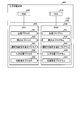
- FIG. 3 is a block diagram of the configuration of the input switching control unit and the control unit of the external switch according to the first embodiment.
- FIG. 4A is an example of a connected device information management table according to the first embodiment.
- FIG. 4B is an example of the connected device information management table updated by the selectable terminal adding unit.
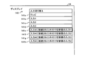
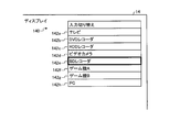
- FIG. 5 is a diagram illustrating an example of the input switching menu displayed on the television display according to the first embodiment.
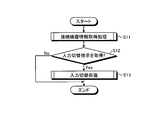
- FIG. 6 is a flowchart of an example of the processing procedure of the input switching control unit according to the first embodiment.
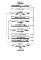
- FIG. 7 is a flowchart of an example of a processing procedure of connected device information acquisition processing according to the first embodiment.
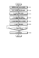
- FIG. 8 is a flowchart of an example of the process procedure of the input switching process according to the first embodiment.
- FIG. 9 is a flowchart of an example of the processing procedure of the control unit of the external switch according to the first embodiment.
- FIG. 10 is a diagram illustrating a connection method between the television and the external switch according to the second embodiment.
- FIG. 11 is a block diagram of the configuration of the input switching control unit and the control unit of the external switch according to the second embodiment.
- FIG. 12 is an example of the connected device information management table according to the third embodiment.
- FIG. 13 is a diagram illustrating an example of the input switching menu image displayed on the television display according to the third embodiment.
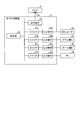
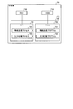
- FIG. 14 is a diagram illustrating an input switching device that executes an input switching instruction program.
- FIG. 15 is a diagram illustrating a switch that executes an input switching execution program.
- FIG. 16A is a diagram illustrating an example of a state in which a plurality of external devices are connected to the television.
- FIG. 16B is a diagram illustrating an example of a state where an external switch is connected to the television.
- FIG. 17 is a diagram illustrating an example of a state in which an input switching operation to a television is performed using a conventional remote controller.
- FIG. 18 is a diagram illustrating an example of a state in which input switching is performed by an operation to a conventional external switch.
- the video display device is a television device (hereinafter simply referred to as “TV”).
- TV television device
- the video display device only needs to be a device that can output a signal received from an external device via an input terminal as video or audio.
- a device other than a television such as a PC (Personal Computer) or a PDA (Personal Digital Assistant). It may be.
- FIG. 1 is a block diagram illustrating the configuration of the television 1 according to the first embodiment.
- the television 1 according to the present embodiment includes an antenna 10, a TV receiver 11, a remote control I / F 12, a plurality of input terminals 13a to 13d, a display 14, a speaker 15, and an operation.
- the television 1 has four input terminals.
- the number of input terminals of the television 1 is not limited to this, and may be only one, for example.
- the TV receiver 11 receives a digital broadcast signal and a terrestrial broadcast signal via the antenna 10.
- the remote control I / F 12 is a light receiving unit that acquires operation information transmitted from the remote control 3 for performing remote operation of the television 1.
- the remote controller 3 corresponds to an operation unit that receives various operations from the user of the television 1.
- the input terminals 13a to 13d acquire signals output from external devices.
- the DVD recorder 4a is input terminal 13a
- the HDD recorder 4b is input terminal 13b
- the video camera 4c is input terminal 13c
- the switch 2 hereinafter referred to as "external" Connected switch ”).
- the input terminals 13a to 13d are digital input terminals such as an HDMI terminal, for example, and can transmit and receive various control signals in addition to acquiring video signals and audio signals.
- the display 14 corresponds to an output means, displays an image based on a digital broadcast signal or a terrestrial broadcast signal acquired from the TV receiver 11 via the antenna 10, or acquired from the external device 4 via the input terminal 13. Or display video based on the signal.
- the speaker 15 corresponds to an output unit, and outputs audio based on a digital broadcast signal or a terrestrial broadcast signal acquired from the TV receiver 11 via the antenna 10, or the external device 4 via the input terminal 13. Or output audio based on the signal obtained from
- the operation unit 16 corresponds to an operation unit and accepts various operations from the user of the television 1. In particular, in the present embodiment, the operation unit 16 receives an input switching operation from the user.
- the control unit 17 controls the entire television 1.
- the control unit 17 according to the present embodiment includes an input switching control unit 100.
- the input switching control unit 100 corresponds to an input switching device and controls input switching of the television 1. A more specific configuration of the input switching control unit 100 will be described later.
- FIG. 2 is a block diagram of the configuration of the external switch 2 according to the first embodiment.
- the external switch 2 according to the present embodiment includes a plurality of input terminals 20a to 20d, a plurality of switches 21a to 21d, an output terminal 22, and a control unit 23.
- the external switch 2 has four input terminals, but the number of input terminals of the external switch 2 is not limited to this.
- the input terminals 20a to 20d are detachably connected to external devices and receive signals output from the connected external devices.
- a BD recorder 4d is connected to the input terminal 20a
- a game machine A4e is connected to the input terminal 20b
- a game machine B4f is connected to the input terminal 20c
- a PC 4g is connected to the input terminal 20d.
- the input terminals 20a to 20d according to the present embodiment are digital input terminals similarly to the input terminals 13a to 13d of the television 1.
- the switches 21a to 21d correspond to the input terminals 20a to 20d, respectively, and are switches pressed by the user when manually switching the input of the external switch 2. For example, when switching the input to the game machine B4f connected to the input terminal 20c, the user switches the input to the input terminal 20c by pressing the switch 21c corresponding to the input terminal 20c.
- the output terminal 22 is detachably connected to another device, and is a terminal for outputting signals received from the external devices 4d to 4g via the input terminals 20a to 20d to the outside.
- the external switch 2 is connected to the television 1 via the output terminal 22 and the input terminal 13d of the television 1.
- the control unit 23 controls the entire external switch 2. A more specific configuration of the control unit 23 will be described later.
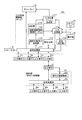
- FIG. 3 is a block diagram illustrating the configuration of the input switching control unit and the control unit of the external switch according to the first embodiment.
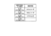
- FIG. 4A is an example of the connected device information management table according to the first embodiment.
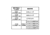
- 4-2 is an example of the connected device information management table updated by the selectable terminal adding unit.
- FIG. 5 is a diagram illustrating an example of an input switching menu displayed on the display of the television according to the first embodiment.
- FIG. 4A shows an example of the connected device information management table when the external switch 2 is not connected to the input terminal 13d.
- the input switching control unit 100 includes a signal processing unit 111, a storage unit 112, an inquiry unit 113, a selectable terminal addition unit 114, an input switching unit 115, and a switching unit.
- An instruction unit 116 and an input switching menu generation unit 117 are provided.
- the signal processing unit 111 outputs the video signal and audio signal output from any one of the input terminals 13 among the video signal and audio signal output from the input terminals 13a to 13d to the display 14 and the speaker 15, respectively. Further, the signal processing unit 111 performs input switching in accordance with an instruction from the input switching unit 115. That is, the signal processing unit 111 switches the input terminal 13 that is a signal output source to the display 14 or the speaker 15 in response to an input switching instruction from the input switching unit 115 described later. Further, the signal processing unit 111 detects that an external device is connected to any of the input terminals 13a to 13d, and reports to the inquiry unit 113 described later that the external device is connected.
- the storage unit 112 stores various information.
- the storage unit 112 has a connected device information management table 150 in a predetermined storage area.
- the connected device information management table 150 stores input terminals that can be selected by an input switching operation using the operation unit 16 or the remote controller 3.
- the connected device information management table 150 stores input terminals 13a to 13d as input terminals that can be selected by an input switching operation using the operation unit 16 or the remote controller 3, as shown in FIG.
- the connected device information management table 150 stores input terminals 13a to 13d as input terminals that can be selected by an input switching operation using the operation unit 16 or the remote controller 3, as shown in FIG.
- the connected device information management table 150 device information of the external device 4 connected to each input terminal 13a to 13d is stored in association with each input terminal 13a to 13d.
- the device information is information indicating the type of the external device connected to the input terminal 13, but may be, for example, the product name or model number of the external device. Such device information is acquired by inquiry processing to the external device 4 by the inquiry unit 113 described later.
- the inquiry unit 113 functions as an inquiry unit together with the signal processing unit 111, and inquires the external switch 2 externally connected to the input terminal 13d of the television 1 about information on the input terminal of the external switch 2. That is, when the inquiry unit 113 receives a report from the signal processing unit 111 that the external switch 2 is connected to the input terminal 13d, the inquiry unit 113 sends the input terminal information to the external switch 2 via the signal processing unit 111.
- the input terminal information is information such as numbers and names of the input terminals 20a to 20d included in the external switch 2.
- the input terminal information may be other information as long as it is information that can determine which input terminal is the input terminal selected by the input switching operation by the user.
- the selectable terminal adding unit 114 functions as a selectable terminal adding unit, and based on the input terminal information acquired from the external switch 2 in response to the query by the query unit 113, the input terminal of the external switch 2 is It is stored in the connected device information management table 150 as selectable input terminals. Specifically, the selectable terminal adding unit 114 can be selected by the operation unit 16 of the television 1 or the remote control 3 when the information indicating that the input terminals 20a to 20d are obtained from the external switch 2 as input terminal information. These input terminals 20a to 20d are added to the connected device information management table 150 as input terminals. As a result, in the connected device information management table 150, as shown in FIG. 4B, the external switch 2 is stored in an area for storing device information corresponding to the input terminal 13d to which the external switch 2 is connected. The input terminals 20a to 20d are stored as input terminals that can be selected by the operation unit 16 or the remote controller 3.
- the input switching unit 115 functions as an input switching unit together with the signal processing unit 111, and performs input switching to the input terminal selected by the input switching operation among the input terminals stored in the connected device information management table 150. Specifically, when the input switching unit 115 acquires an input switching operation via the operation unit 16 or the remote control I / F 12, the input switching unit 115 refers to the connected device information management table 150 and determines the input terminal selected by the operation. . Then, the input switching unit 115 instructs the signal processing unit 111 to switch the input to the determined input terminal.
- the switching instruction unit 116 functions as a switching instruction unit together with the signal processing unit 111.
- the switching instruction unit 116 is connected to the external switching device 2. Instructs input switching to the input terminal.
- the switching instruction unit 116 instructs the external switch 2 to connect the input terminal to the output terminal 22 of the external switch 2.
- the input switching menu generation unit 117 functions as an input switching menu display unit, and is referred to by the user when the user performs an input switching operation using the operation unit 16 or the remote controller 3 based on the connected device information management table 150.
- a switching menu image is generated, and the input switching menu image is displayed on the display 14. That is, the input switching menu generation unit 117 generates an input switching menu image in which a column for selecting an input terminal stored in the connected device information management table 150 is provided.
- the display 14 has an input switching menu image 140 in which the television input terminals 13a to 13c and the input terminals 20a to 20d of the external switch 2 can be selected by the operation unit 16 or the remote controller 3. Is displayed. For example, when the user wants to switch the input to the BD recorder 4d connected to the input terminal 20a of the external switch 2, the user presses an input switching button provided on the remote controller 3, for example, and moves the cursor to the input terminal 20a with the up and down buttons. And press the enter button. As a result, the input terminal 20a is selected as the input terminal to be input switched.
- the input switching operation may be an operation of repeatedly pressing an input switching button provided on the remote controller 3 or the operation unit 16 until switching to the input terminal.
- the control unit 23 of the external switch 2 includes a signal processing unit 231 and a signal switching control unit 232.
- the signal processing unit 231 sends video signals and audio signals output from any one of the input terminals 20 among the video signals and audio signals output from the input terminals 20a to 20d to the television 1 via the output terminal 22, respectively. Output.
- the signal processing unit 231 performs input switching in response to an operation by the user to the switches 21a to 21d or an instruction from the signal switching control unit 232 described later. Specifically, the signal processing unit 231 connects one input terminal 20 of the plurality of input terminals to the output terminal 22 as input switching.
- the signal processing unit 231 functions as an information transmission unit, and transmits input terminal information to the television 1 via the output terminal 22 in response to an inquiry from the inquiry unit 113 of the television 1.
- the signal switching control unit 232 functions as an input switching unit together with the signal processing unit 231, and performs input switching to one input terminal among a plurality of input terminals based on an input switching instruction from the television 1. Specifically, when the signal switching control unit 232 acquires the input switching instruction from the switching instruction unit 116 of the television 1 through the output terminal, the signal switching control unit 232 performs input switching to the signal processing unit 231 based on the input switching instruction. Instruct.
- FIG. 6 is a flowchart of an example of the processing procedure of the input switching control unit according to the first embodiment.
- the input switching control unit 100 When the power is turned on, the input switching control unit 100 according to the present embodiment first performs connected device information acquisition processing as shown in FIG. 6 (step S11).
- This connected device information acquisition process is a process of acquiring device information from the external device 4 connected to the input terminals 13a to 13d. In particular, the input device information is acquired from the external switch 2.
- This connected device information acquisition processing is processing from steps S101 to S111 in FIG. 7, and will be described later.
- the input switching unit 115 determines whether or not an input switching menu display operation has been acquired from the remote control I / F 12 or the operation unit 16 (step S12).
- the input switching menu display operation is an operation in which the user presses an “input switching display menu display button” provided on the operation unit 16 or the remote controller 3. If it is determined in this process that an input switching menu display operation has been acquired (Yes at step S12), the input switching control unit 100 performs an input switching process (step S13).
- This input switching process is a process of switching an input terminal that is an output source to the display 14 or the speaker 15 in accordance with an input switching process by the user.
- input switching of the external switch 2 is performed by an input switching operation on the television 1 side using the remote controller 3 or the operation unit 16.
- This input switching process is a process from steps S121 to S128 in FIG. 8, and will be described later.
- FIG. 7 is a flowchart of an example of a processing procedure of connected device information acquisition processing according to the first embodiment.
- the input switching control unit 100 initializes the connected device information management table 150 stored in the storage unit 112 (step S101).
- the signal processing unit 111 detects the external device connected to the input terminals 13a to 13d for each input terminal 13 (step S102). Then, the signal processing unit 111 determines whether or not an external device is connected to the input terminal 13 that has performed the detection process (step S103). In this process, when it is determined that an external device is connected to the input terminal 13 (Yes at Step S103), the signal processing unit 111 proceeds to Step S104.
- step S104 the inquiry unit 113 inquires of the detected external device about the device type via the input terminal that has performed the detection.
- the inquiry unit 113 determines whether the external device is the external switch 2 based on device information transmitted from the external device in response to the inquiry (step S105).
- the inquiry unit 113 is an external switch that can be switched on the TV 1 side with respect to the external switch 2.
- An inquiry is made as to whether or not there is (step S106). That is, the inquiry unit 113 inquires of the external switch 2 whether or not it has a function of performing input switching based on the input switching instruction transmitted from the switching instruction unit 116.
- the inquiry unit 113 determines whether or not the external switch 2 is an external switch that can be switched on the television side, based on the response information from the external switch 2 for the inquiry in step S105. (Step S107). In this process, if it is determined that the external switch 2 is an external switch that can be switched on the television side (Yes at step S107), the process proceeds to step S108.
- step S108 the inquiry unit 113 inquires of the external switch 2 about input terminal information.
- the selectable terminal adding unit 114 stores the input terminal information in the connected device information management table 150.
- Step S110 the selectable terminal adding unit 114 is an input terminal of the external switch 2 as an input terminal that can be selected by the remote control 3 or the operation unit 16 of the television 1 based on the input terminal information acquired from the external switch 2. 20a to 20d are added to the connected device information management table 150.
- the selectable terminal adding unit 114 stores the device information acquired in step S104 in the connected device information management table 150 as device information corresponding to the input terminal (step S110).
- the signal processing unit 111 determines whether or not the processing from steps S102 to S110 has been performed for all the input terminals 13a to 13d (step S111). In this process, when the processes from step S102 to S110 are not performed for all the input terminals 13a to 13d (No in step S111), the signal processing unit 111 shifts the process to step S102. On the other hand, when it is determined that the processing from step S102 to S110 has been performed for all the input terminals 13a to 13d (Yes at step S111), or when no external device is connected to the input terminal 13 at step S1-3 ( In step S103, the signal processing unit 111 ends the connected device information acquisition process.
- FIG. 8 is a flowchart of an example of the process procedure of the input switching process according to the first embodiment.
- the input switching unit 115 extracts information from the connected device information management table 150 (step S121), and generates an input switching menu image based on the extracted information (step S121). In step S122, the generated input switching menu image is displayed on the display 14 (step S123).
- step S124 when the input switching unit 115 acquires an input switching operation from the remote control I / F 12 or the operation unit 16 (step S124), an external device that is an input switching target by the input switching operation is an input terminal of the external switch 2. It is determined whether the external device is connected to 20 (step S125). In this process, when it is determined that the external device to be input switched is an external device connected to the external switch 2 (Yes at Step S125), the switching instruction unit 116 An input switching instruction indicating that the input should be switched is transmitted to the input terminal 20 to which the external device is connected (step S126).
- step S126 When the process of step S126 is completed, or when the external device to be input switched is not an external device connected to the external switch 2 (No in step S125), the input switching unit 115 acquires in step S124. Based on the input switching operation, the input terminal 13 on the television 1 side is switched (step S127). For example, when the “input 1” field 141b of the input switching menu image is selected by the user's input switching operation (see FIG. 5), the input switching unit 115 is connected to the input terminal 13a corresponding to “input 1”. An instruction to switch the input is transmitted to the signal processing unit 111. Then, the signal processing unit 111 performs input switching to the input terminal 13a based on this instruction.
- the input switching unit 115 corresponds to “input 4”.
- An instruction to switch the input to the input terminal 13d is transmitted to the signal processing unit 111.
- the signal processing unit 111 performs input switching to the input terminal 13d based on this instruction.
- the signal processing unit 111 outputs video and audio based on the signal acquired from the input terminal 13 switched in step S127 to the display 14 and the speaker 15 (step S128).
- the input switching control unit 100 ends the input switching process.
- the input switching process is started in response to an operation on the input switching menu display button.
- an operation on the input switching button may be used as an opportunity. That is, for example, when a video based on a digital broadcast signal acquired via the antenna 10 is displayed, when the user presses the input switching button on the remote control 3 or the operation unit 16, the input switching control unit 100 displays the display. 14 displays the input switching menu image 140 and switches the input to input 1 (input terminal 13a). The input switching control unit 100 performs input switching processing every time the user presses the input switching button.
- FIG. 9 is a flowchart of an example of a processing procedure of the control unit 23 of the external switch 2 according to the first embodiment. Note that the following processing shows only processing related to input switching among various operations performed by the control unit 23 of the external switch 2.
- step S131 when the signal processing unit 231 of the external switch 2 acquires a device type inquiry from the inquiry unit 113 of the television 1 via the output terminal 22 (step S131), the response information to the inquiry is obtained as response information.
- the fact that the device type is an external switch is transmitted (step S132).
- step S133 when the signal processing unit 231 obtains an inquiry from the inquiry unit 113 as to whether or not it is an external switch capable of input switching on the television 1 side (step S133), the television 1 as response information to the inquiry.
- step S134 The fact that it is an external switch capable of input switching on the side
- step S135 when the signal processing unit 231 obtains an inquiry about the input terminal information from the inquiry unit 113 (step S135), the signal processing unit 231 transmits the input terminal information as response information to the inquiry (step S136).
- the signal switching control unit 232 determines whether or not an input switching instruction has been acquired from the television 1 (step S137). In this process, if it is determined that an input switching instruction has been acquired from the television 1 (Yes at step S137), the signal switching control unit 232 switches the input terminal 20 that is an output source to the television 1 based on the input switching instruction.
- the signal processing unit 111 is instructed (step S138).
- the input terminal 13 of the television 1 and the input terminal 20 of the external switch 2 are switched. This can be performed collectively using the remote control 3 or the operation unit 16 of the television 1. Therefore, the complexity of the input switching operation when performing input switching to an external device connected to the external switch 2 can be eliminated.
- the input switch menu image 140 is displayed on the display 14 based on the connected device information management table 150.
- the user refers to the input switching menu image 140 displayed on the display 14 and selects one input terminal to switch the input from among the input terminal 13 of the television 1 and the input terminal 20 of the external switch 2.
- the input switching operation can be performed more comfortably.
- the input terminals 13a to 13d of the television 1 are digital terminals, and control signals such as input switching instructions and various inquiries are transmitted and received via the input terminals 13a to 13d.
- the input terminal provided on the television 1 is an analog terminal such as the D terminal
- input to an external device connected to the external switch by the remote control 3 or the operation unit 16 of the television 1 is performed.
- FIG. 10 is a diagram illustrating a connection method between the television and the external switch according to the second embodiment
- FIG. 11 illustrates the configuration of the input switching control unit and the control unit of the external switch according to the second embodiment. It is a block diagram.
- the input terminal provided on the television 1 is not a digital terminal but an analog terminal, it is connected to the external switch 2 using the remote control 3 or the operation unit 16 of the television 1 by using a signal line for device control. It is possible to switch the input to the external device. That is, in such a case, as shown in FIG. 10, the television 1 according to the present embodiment transmits and receives control signals in addition to the input terminals 18a to 18d that are analog terminals (here, D terminals). The control signal terminal 19 is provided.
- the external switch 2 according to the present embodiment also has a control signal terminal 24.
- the television 1 and the external switch 2 are connected by a device control signal line 180 such as RS-232C (Recommended Standard 232 version C).
- the signal processing unit 111 of the television 1 receives an instruction to transmit various inquiries from the inquiry unit 113 or transmits an input switching instruction from the switching instruction unit 116. When receiving the instructions, these are transmitted to the external switch 2 via the control signal terminal 19. Further, the signal processing unit 111 acquires response information for various inquiries via the control signal terminal 19.
- the signal processing unit 231 of the external switch 2 acquires various inquiries from the inquiry unit 113 via the control signal terminal 24, and sends response information for these inquiries to the control signal terminal 24. To the TV 1.
- the signal switching control unit 232 acquires an input switching instruction from the switching instruction unit 116 via the control signal terminal 24.
- the television 1 has, as input terminals, video / audio signal terminals (corresponding to the input terminals 18a to 18d) for acquiring video signals and audio signals, and control signal terminals for transmitting / receiving control signals.
- the external switch 2 has a control signal terminal 24 for transmitting and receiving control signals. Then, transmission / reception of various inquiries and input switching instructions are performed via these control signal terminals 19 and 24. Thereby, even if the input terminal provided in the television 1 is an analog terminal, it is possible to perform input switching to the external device connected to the external switch 2 by the remote control 3 or the operation unit 16 of the television 1.
- FIG. 12 is an example of a connected device information management table according to the third embodiment
- FIG. 13 is a diagram illustrating an example of an input switching menu image displayed on the display of the television according to the third embodiment.
- the input terminal information is transmitted from the external switch 2 to the television 1, the device information of the external device connected to the external switch 2 is also transmitted.
- the device information is information indicating the type of the external device or information indicating the product name or model number of the external device.
- the external switch 2 acquires device information from the external device when the external device is connected to the input terminal 20 of the external switch 2, and the terminal of the input terminal 20 to which the external device is connected.
- the number is stored in a storage unit (not shown) in association with the number.
- the selectable terminal adding unit 114 updates the connected device information management table 150 based on the device information.
- the connected device information management table 150 device information of the external device connected to the external switch 2 is stored in association with the input terminal 20 to which the external device is connected. .
- the input switching menu generation unit 117 generates an input switching menu image based on the connected device information management table 150 and displays it on the display 14.
- the fields 142e to 142h corresponding to the input terminals 20a to 20d of the external switch 2 in the input switching menu image 140 are displayed in the external devices connected to the input terminals 20a to 20d. Device information is displayed. Therefore, the user can more clearly grasp which column of the input switching menu image 140 should be selected when performing an input switching operation to an external device connected to the external switch 2.
- FIG. 14 is a diagram illustrating an input switching device that executes an input switching instruction program.
- the input switching device 600 is configured by connecting an HDD 610, a CPU 620, a ROM 630, and a RAM 640 via a bus 650.
- an input switching instruction program that exhibits the same function as in the above embodiment, that is, as shown in FIG. 14, a storage program 631, an inquiry program 632, a selectable terminal addition program 633, an input switching program 634, a switching An instruction program 635 is stored in advance.
- the CPU 620 reads out these programs 631 to 635 from the ROM 630 and executes them, whereby the programs 631 to 635 are stored in the storage process 621, the inquiry process 622, the selectable terminal addition process 623, the input switching process 624, and the switching, respectively. Functions as an instruction process 625.
- the CPU 620 corresponds to the input switching control unit 100 shown in FIG.
- the HDD 610 stores various data used by the processes 621 to 625.
- the CPU 620 reads out various data stored in the HDD 610 and stores it in the RAM 640, and the processes 621 to 625 execute various processes such as an input switching process using the various data stored in the RAM 640.
- FIG. 15 is a diagram illustrating a switch that executes an input switching execution program.
- the switching device 700 as the control unit 23 of the external switching device 2 is configured by connecting an HDD 710, a CPU 720, a ROM 730, and a RAM 740 with a bus 750.
- the ROM 730 stores in advance an input switching execution program that exhibits the same function as in the above embodiment, that is, an information transmission program 731 and an input switching program 732 as shown in FIG.
- the CPU 720 reads out these programs 731 and 732 from the ROM 730 and executes them, the programs 731 and 732 function as an information transmission process 721 and an input switching process 722, respectively.
- the CPU 720 corresponds to the control unit 23 shown in FIG.
- the HDD 710 stores various data used by the processes 721 and 722.
- the CPU 720 reads out various data stored in the HDD 710 and stores it in the RAM 740, and the processes 721 and 722 execute various processes using the various data stored in the RAM 740.
- the switch disclosed in this case is not necessarily external. There is no.
Landscapes
- Engineering & Computer Science (AREA)
- Multimedia (AREA)
- Signal Processing (AREA)
- Details Of Television Systems (AREA)
Abstract
切替器を映像表示装置に着脱可能に接続した場合に、入力切替操作が煩雑になることを防止することを課題とする。この課題を解決するために、入力切替制御部(100)は、外付け切替器より取得した入力端子情報に基づき、外付け切替器が有する入力端子(20)を、テレビの有する操作手段への入力切替操作により選択可能な入力端子として記憶し、ユーザによる入力切替操作を取得すると、この情報に基づき入力切替を行う。このとき、ユーザにより選択された入力端子が外付け切替器の有する入力端子(20)である場合、入力切替制御部(100)は、外付け切替器に対して当該入力端子(20)への入力切替を指示する。
Description
この発明は、入力切替装置、切替器、映像表示装置、入力切替指示プログラム、入力切替実行プログラム及び入力切替方法に関する。
従来、テレビやPC(Personal Computer)等の映像表示装置は、外部機器からの信号を取得するための入力端子を複数有する。映像表示装置のユーザは、リモコンや入力切替えボタン等を用いて入力切替操作を行うことにより、任意の外部機器からの出力映像をディスプレイに表示させることができる。複数の入力端子を備える映像表示装置として、例えば特許文献1には、入力切替えの順番を可変とする映像表示装置が開示されている。この映像表示装置によれば、求める映像に切替わるまでの操作の回数を減らすことができる。
また、近年では、複数の入力端子を備え、他装置に着脱可能に接続される外付けの外部入力切替器(以下、「外付け切替器」とする。)も市販されており、この外付け切替器を映像入力装置に接続することにより、映像表示装置に接続可能な外部機器の数を増やすことができる。例えば、図16-1に示すように、4つの入力端子510a~510dを有するテレビ500があり、入力端子510aに旧世代録画機器520a、入力端子510bに旧世代録画機器520b、入力端子510cにDVDレコーダ520cが接続されているとする。
このとき、テレビ500に更に4つの外部機器(BD(Blue-ray Disk))レコーダ520d、ゲーム機A520e、ゲーム機B520f、PC520g)を接続したい場合、図16-2に示すように、入力端子510dに外付け切替器530を接続する。外付け切替器530は、複数の入力端子540a~540dを有しており、これら入力端子540a~540dにそれぞれBDレコーダ520d、ゲーム機A520e、ゲーム機B520f、PC520gを接続することで、全ての外部機器520をテレビ500に接続することができる。
このように、外付け切替器530を用いることにより、映像表示装置に接続可能な外部機器の数が増えるため、入力端子数よりも多くの外部機器520を映像表示装置に接続することができる。特に、現在使用されている映像表示装置には、D端子やHDMI(High-Definition Multimedia Interface)端子のように世代の異なる入力端子を有するものが多い。そのため、外部機器の世代交代が進むにつれ、古い世代の入力端子は使われなくなり、実質的に使用できる入力端子の数が減るおそれもあり、今後、外付け切替器が利用される機会は増えると考えられる。
しかしながら、映像表示装置に外付け切替器を接続した場合、外付け切替器に接続された外部機器からの信号を映像表示装置へ出力するための入力切替操作が煩雑となるおそれがある。すなわち、例えば、外付け切替器530の入力端子540cに接続されたゲーム機B520fに入力を切替えたい場合、ユーザは、図17に示すように、先ず、例えばリモコン580を用いて入力4(入力端子510dに対応)に切替える。なお、この際、テレビ500のディスプレイ560には、例えば、入力切替メニュー570が表示される。この入力切替メニュー570には、各入力端子510に対応する欄が設けられており、ユーザが、リモコン580等を用いて所望の入力端子510に対応する欄を選択することにより入力の切替えが行われる。
続いて、ユーザは、図18に示すように、外付け切替器530に設けられた入力切替え用のスイッチ550a~550dのうち、ゲーム機B520fが接続された入力端子540cに対応するスイッチ550cを押下する。これにより、映像表示装置には、ゲーム機B520fからの信号をディスプレイ560やスピーカ(図示せず)等に出力される。このように、外付け切替器に接続された外部機器への入力切替えを行う場合、ユーザは、映像表示装置側及び外付け切替器側の2つの操作を行わなくてはならないため、煩雑である。
開示の技術は、上述した従来技術による問題点を解消するためになされたものであり、切替器を映像表示装置に接続した場合において、入力切替操作が煩雑になることを防止できる入力切替装置、切替器、映像表示装置、入力切替指示プログラム、入力切替実行プログラム及び入力切替方法を提供することを目的とする。
上述した課題を解決し、目的を達成するため、本件に開示する入力切替装置は、一つの態様として、複数の入力端子を有する映像表示装置の入力切替を制御する入力切替装置であって、前記映像表示装置の有する操作手段への入力切替操作により選択可能な入力端子を所定の記憶領域に記憶する記憶手段と、前記映像表示装置に外部接続された切替器へ当該切替器が有する入力端子の情報を問合せる問合せ手段と、前記問合せ手段による問合せにより取得した前記切替器の入力端子情報に基づき、前記切替器が有する入力端子を、前記選択可能な入力端子として前記所定の記憶領域に記憶する選択可能端子追加手段と、前記記憶手段に記憶された入力端子のうち、前記操作手段への入力切替操作により選択された入力端子への入力切替を行う入力切替手段と、前記選択された入力端子が、前記切替器の有する入力端子である場合、前記切替器に対して当該入力端子への入力切替を指示する切替指示手段とを有する。
本件に開示する入力切替装置、切替器、映像表示装置、入力切替指示プログラム、入力切替実行プログラム及び入力切替方法の一つの態様によれば、切替器に接続された外部機器への入力切替を映像表示装置側の入力切替操作により行うため、入力切替操作の煩雑さを解消できるという効果を奏する。
1 テレビ(映像表示装置)
2 外付け切替器
3 リモコン
4a~4g 外部機器
13a~13d 入力端子
10 アンテナ
11 TV受信部
12 リモコンI/F
13a~13d 入力端子
14 ディスプレイ
15 スピーカ
16 操作部
17 制御部
20a~20d 入力端子
21a~21d スイッチ
22 出力端子
23 制御部
100 入力切替制御部
111 信号処理部
112 記憶部
113 問合せ部
114 選択可能端子追加部
115 入力切替部
116 切替指示部
117 入力切替メニュー生成部
140 入力切替メニュー画像
171 接続機器情報管理テーブル
231 信号処理部
232 信号切替制御部
2 外付け切替器
3 リモコン
4a~4g 外部機器
13a~13d 入力端子
10 アンテナ
11 TV受信部
12 リモコンI/F
13a~13d 入力端子
14 ディスプレイ
15 スピーカ
16 操作部
17 制御部
20a~20d 入力端子
21a~21d スイッチ
22 出力端子
23 制御部
100 入力切替制御部
111 信号処理部
112 記憶部
113 問合せ部
114 選択可能端子追加部
115 入力切替部
116 切替指示部
117 入力切替メニュー生成部
140 入力切替メニュー画像
171 接続機器情報管理テーブル
231 信号処理部
232 信号切替制御部
以下に添付図面を参照して、本件に開示する入力切替装置、切替器、映像表示装置、入力切替指示プログラム、入力切替実行プログラム及び入力切替方法の実施例を図面に基づいて詳細に説明する。なお、本実施例において映像表示装置は、テレビジョン装置(以下、単に「テレビ」とする。)とする。ただし、映像表示装置は、外部機器から入力端子を介して受信した信号を映像や音声として出力できる装置であればよく、例えば、PC(Personal Computer)やPDA(Personal Digital Assistant)などテレビ以外の装置であってもよい。
まず、本実施例にかかる映像表示装置の概略構成について図面を用いて説明する。図1は実施例1にかかるテレビ1の構成を示すブロック図である。図1に示すように、本実施例にかかるテレビ1は、アンテナ10と、TV受信部11と、リモコンI/F12と、複数の入力端子13a~13dと、ディスプレイ14と、スピーカ15と、操作部16と、制御部17とを有する。なお、本実施例において、テレビ1は、4つの入力端子を有することとしたが、テレビ1の有する入力端子の数は、これに限ったものではなく、例えば1つだけであってもよい。
TV受信部11は、アンテナ10を介してデジタル放送信号や地上波放送信号を受信する。リモコンI/F12は、テレビ1の遠隔操作を行うためのリモコン3から送信される操作情報を取得する受光部である。リモコン3は、テレビ1のユーザからの各種操作を受け付ける操作手段に相当する。入力端子13a~13dは、外部機器から出力される信号を取得する。本実施例においては、図1に示すように、入力端子13aにDVDレコーダ4a、入力端子13bにHDDレコーダ4b、入力端子13cにビデオカメラ4c、そして入力端子13dに切替器2(以下、「外付け切替器」とする)が接続されている。なお、本実施例にかかる入力端子13a~13dは、例えばHDMI端子のようなデジタル入力端子であり、映像信号や音声信号を取得するだけでなく、各種の制御信号を送受信することができる。
ディスプレイ14は、出力手段に相当し、アンテナ10を介してTV受信部11から取得したデジタル放送信号や地上波放送信号に基づく映像を表示したり、入力端子13を介して外部機器4から取得した信号に基づく映像を表示したりする。同様に、スピーカ15は、出力手段に相当し、アンテナ10を介してTV受信部11から取得したデジタル放送信号や地上波放送信号に基づく音声を出力したり、入力端子13を介して外部機器4から取得した信号に基づく音声を出力したりする。操作部16は、操作手段に相当し、テレビ1のユーザからの各種操作を受け付ける。特に、本実施例において、操作部16は、ユーザからの入力切替操作を受け付ける。
制御部17は、テレビ1全体を制御する。特に、本実施例にかかる制御部17は、入力切替制御部100を有する。この入力切替制御部100は、入力切替装置に相当し、テレビ1の入力切替の制御を行う。入力切替制御部100のより具体的な構成については、後述する。
続いて、本実施例にかかる外付け切替器2の概略構成について図面を用いて説明する。図2は、実施例1にかかる外付け切替器2の構成を示すブロック図である。図2に示すように、本実施例にかかる外付け切替器2は、複数の入力端子20a~20dと、複数のスイッチ21a~21dと、出力端子22と、制御部23とを有する。なお、本実施例において、外付け切替器2は、4つの入力端子を有することとしたが、外付け切替器2の有する入力端子の数は、これに限ったものではない。
入力端子20a~20dは、外部機器に着脱可能に接続され、接続された外部機器から出力される信号を受信する。本実施例においては、図2に示すように、入力端子20aにBDレコーダ4d、入力端子20bにゲーム機A4e、入力端子20cにゲーム機B4f、入力端子20dにPC4gが接続されている。なお、本実施例にかかる入力端子20a~20dは、テレビ1の入力端子13a~13dと同様デジタル入力端子とする。スイッチ21a~21dは、それぞれ入力端子20a~20dに対応し、外付け切替器2の入力切替を手動で行う際、ユーザによって押下されるスイッチである。例えば、入力端子20cに接続されたゲーム機B4fに入力を切替えたい場合、ユーザは、この入力端子20cに対応するスイッチ21cを押すことにより入力端子20cへの入力切替が行われる。
出力端子22は、他装置に着脱可能に接続されるものであり、入力端子20a~20dを介して外部機器4d~4gから受信した信号を外部に出力するための端子である。本実施例において、外付け切替器2は、出力端子22及びテレビ1の入力端子13dを介してテレビ1と接続している。制御部23は、外付け切替器2全体を制御する。この制御部23のより具体的な構成については、後述する。
続いて、本実施例にかかるテレビ1の入力切替制御部100及び外付け切替器2の制御部23のより具体的な構成について図面を参照して説明する。図3は実施例1にかかる入力切替制御部及び外付け切替器の制御部の構成を示すブロック図であり、図4-1は実施例1にかかる接続機器情報管理テーブルの一例であり、図4-2は選択可能端子追加部により更新された接続機器情報管理テーブルの一例である。また、図5は実施例1にかかるテレビのディスプレイに表示される入力切替メニューの一例を示す図である。なお、図4-1は、入力端子13dに外付け切替器2が接続されていない場合における接続機器情報管理テーブルの一例を示している。
図3に示すように、本実施例にかかる入力切替制御部100は、信号処理部111と、記憶部112と、問合せ部113と、選択可能端子追加部114と、入力切替部115と、切替指示部116と、入力切替メニュー生成部117とを有する。
信号処理部111は、入力端子13a~13dからそれぞれ出力される映像信号や音声信号のうち、何れか1つの入力端子13から出力される映像信号や音声信号をディスプレイ14やスピーカ15に出力する。また、信号処理部111は、入力切替部115からの指示に応じて入力切替を行う。すなわち、信号処理部111は、後述する入力切替部115からの入力切替指示に応じて、ディスプレイ14やスピーカ15への信号の出力元となる入力端子13を切替える。また、信号処理部111は、入力端子13a~13dの何れかに外部機器が接続されたことを検出するとともに、当該外部機器が接続された旨を後述する問合せ部113に報告する。
記憶部112は、各種情報を記憶する。特に、記憶部112は、所定の記憶領域に接続機器情報管理テーブル150を有する。接続機器情報管理テーブル150は、操作部16やリモコン3を用いた入力切替操作により選択可能な入力端子を記憶する。具体的には、接続機器情報管理テーブル150には、図4-1に示すように、操作部16やリモコン3を用いた入力切替操作により選択可能な入力端子として入力端子13a~13dが記憶される。
また、接続機器情報管理テーブル150において、各入力端子13a~13dに接続された外部機器4の機器情報が、各入力端子13a~13dと関連付けられて記憶される。例えば、入力端子13aに接続された外部機器がDVDレコーダ4aである場合、接続機器情報管理テーブル150の入力端子13aに対応する機器情報として、「DVDレコーダ」が記憶される。なお、本実施例において、機器情報は、入力端子13に接続された外部機器の種別を示す情報としたが、例えば、当該外部機器の製品名や型番等であってもよい。このような機器情報は、後述する問合せ部113による外部機器4への問合せ処理により取得される。
問合せ部113は、信号処理部111と共に問合せ手段として機能し、テレビ1の入力端子13dに外部接続された外付け切替器2へ当該外付け切替器2が有する入力端子の情報を問合せる。すなわち、問合せ部113は、入力端子13dに外付け切替器2が接続された旨の報告を信号処理部111から受けると、外付け切替器2に対して入力端子情報を信号処理部111を介して問合せる。ここで、入力端子情報とは、外付け切替器2が有する各入力端子20a~20dの番号や名前などの情報である。なお、入力端子情報は、ユーザによる入力切替操作により選択された入力端子がどの入力端子であるかが判定できる情報であれば他の情報であってもよい。
選択可能端子追加部114は、選択可能端子追加手段として機能し、問合せ部113による問合せに応じて外付け切替器2より取得した入力端子情報に基づき、外付け切替器2が有する入力端子を、選択可能な入力端子として接続機器情報管理テーブル150に記憶する。具体的には、選択可能端子追加部114は、入力端子20a~20dを有する旨の情報を入力端子情報として外付け切替器2から取得すると、テレビ1の操作部16やリモコン3により選択可能な入力端子としてこれら入力端子20a~20dを接続機器情報管理テーブル150に追加する。これにより、接続機器情報管理テーブル150には、図4-2に示すように、外付け切替器2が接続されている入力端子13dに対応する機器情報を記憶する領域に、外付け切替器2の入力端子20a~20dが、操作部16やリモコン3により選択可能な入力端子として記憶される。
入力切替部115は、信号処理部111と共に入力切替手段として機能し、接続機器情報管理テーブル150に記憶された入力端子のうち、入力切替操作によって選択された入力端子への入力切替を行う。具体的には、入力切替部115は、操作部16又はリモコンI/F12を介して入力切替操作を取得すると、接続機器情報管理テーブル150を参照して当該操作により選択された入力端子を判別する。そして、入力切替部115は、当該判別した入力端子に入力を切替えるよう信号処理部111に指示する。
切替指示部116は、信号処理部111と共に切替指示手段として機能し、入力切替操作により選択された入力端子が、外付け切替器2の有する入力端子である場合、外付け切替器2に対して当該入力端子への入力切替を指示する。具体的には、切替指示部116は、当該入力端子を外付け切替器2の有する出力端子22と接続することを外付け切替器2に対して指示する。
入力切替メニュー生成部117は、入力切替メニュー表示手段として機能し、接続機器情報管理テーブル150に基づき、ユーザが操作部16やリモコン3を用いて入力切替操作を行う際にユーザにより参照される入力切替メニュー画像を生成し、当該入力切替メニュー画像をディスプレイ14に表示させる。すなわち、入力切替メニュー生成部117は、接続機器情報管理テーブル150に記憶されている入力端子を選択する欄が設けられた入力切替メニュー画像を生成する。
これにより、図5に示すように、ディスプレイ14には、テレビの入力端子13a~13c及び外付け切替器2の入力端子20a~20dを操作部16やリモコン3により選択可能な入力切替メニュー画像140が表示される。例えば、外付け切替器2の入力端子20aに接続されたBDレコーダ4dに入力を切替えたい場合、ユーザは、例えばリモコン3に設けられた入力切替ボタンを押すとともに、上下ボタンによりカーソルを入力端子20aに対応する欄141eに位置させて決定ボタンを押す。これにより、入力切替の対象となる入力端子として入力端子20aが選択される。なお、入力切替操作は、入力端子に切替わるまでリモコン3や操作部16に設けられた入力切替ボタンを繰り返し押す操作でもよい。
また、図3に示すように、外付け切替器2の制御部23は、信号処理部231と、信号切替制御部232とを有する。信号処理部231は、入力端子20a~20dからそれぞれ出力される映像信号や音声信号のうち、何れか1つの入力端子20から出力される映像信号や音声信号を出力端子22を介してテレビ1に出力する。
また、信号処理部231は、ユーザによるスイッチ21a~21dへの操作又は後述する信号切替制御部232からの指示に応じて入力切替を行う。具体的には、信号処理部231は、入力切替として、複数の入力端子のうち一の入力端子20を出力端子22と接続する。また、信号処理部231は、情報送信手段として機能し、テレビ1の問合せ部113からの問合せに応じて、入力端子情報を出力端子22を介してテレビ1に送信する。
信号切替制御部232は、信号処理部231と共に入力切替手段として機能し、テレビ1からの入力切替指示に基づき、複数の入力端子のうち一の入力端子への入力切替えを行う。具体的には、信号切替制御部232は、テレビ1の切替指示部116からの入力切替指示を出力端子を介して取得すると、当該入力切替指示に基づき、信号処理部231に対して入力切替を指示する。
次に、本実施例にかかるテレビ1の入力切替制御部100の具体的動作について図面を参照して説明する。図6は、実施例1にかかる入力切替制御部の処理手順の一例を示すフローチャートである。
本実施例にかかる入力切替制御部100は、電源が投入されると、先ず、図6に示すように、接続機器情報取得処理を行う(ステップS11)。この接続機器情報取得処理は、入力端子13a~13dに接続された外部機器4から機器情報を取得する処理であり、特に、外付け切替器2から入力端子情報を取得する。この接続機器情報取得処理は、図7におけるステップS101~S111までの処理であり、後述する。
続いて、入力切替部115は、リモコンI/F12または操作部16から入力切替メニュー表示操作を取得したか否かを判定する(ステップS12)。入力切替メニュー表示操作とは、ユーザが操作部16又はリモコン3に設けられた「入力切替表示メニュー表示ボタン」を押下する操作である。この処理において、入力切替メニュー表示操作を取得したと判定すると(ステップS12肯定)、入力切替制御部100は、入力切替処理を行う(ステップS13)。この入力切替処理は、ユーザによる入力切替処理に応じて、ディスプレイ14やスピーカ15への出力元となる入力端子を切替える処理である。特に、本実施例にかかる入力切替処理では、リモコン3や操作部16を用いたテレビ1側での入力切替操作により、外付け切替器2の入力切替を行う。この入力切替処理は、図8における、ステップS121~S128までの処理であり、後述する。
続いて、ステップS11における接続機器情報取得処理について、図7を参照して具体的に説明する。図7は、実施例1にかかる接続機器情報取得処理の処理手順の一例を示すフローチャートである。
図7に示すように、接続機器情報取得処理を開始すると、入力切替制御部100は、記憶部112に記憶された接続機器情報管理テーブル150を初期化する(ステップS101)。初期化を終えると、信号処理部111は、入力端子13a~13dに接続される外部機器の検出を入力端子13ごとに行う(ステップS102)。そして、信号処理部111は、検出処理を行った入力端子13に外部機器が接続されているか否かを判定する(ステップS103)。この処理において、当該入力端子13に外部機器が接続されていると判定すると(ステップS103肯定)、信号処理部111は、処理をステップS104へ移行する。
ステップS104において、問合せ部113は、検出された外部機器に対して当該検出を行った入力端子を介して機器種別の問合わせを行う。次に、問合せ部113は、当該問合わせに対して外部機器から送信される機器情報に基づき、当該外部機器が外付け切替器2であるか否かを判定する(ステップS105)。この処理において、当該外部機器が外付け切替器2であると判定すると(ステップS105肯定)、問合せ部113は、外付け切替器2に対して、テレビ1側で切替可能な外付け切替器であるか否かを問合せる(ステップS106)。すなわち、問合せ部113は、外付け切替器2に対して、切替指示部116により送信される入力切替指示に基づき入力切替を行う機能を有しているか否かを問合せる。
続いて、問合せ部113は、ステップS105における問合せに対する外付け切替器2からの応答情報に基づき、当該外付け切替器2がテレビ側で切替え可能な外付け切替器であるか否かを判定する(ステップS107)。この処理において、当該外付け切替器2がテレビ側で切替え可能な外付け切替器であると判定すると(ステップS107肯定)、処理をステップS108へ移行する。
ステップS108において、問合せ部113は、外付け切替器2に対して、入力端子情報を問合せる。そして、当該問合わせに応じて外付け切替器2から送信された入力端子情報を取得すると(ステップS109)、選択可能端子追加部114は、当該入力端子情報を接続機器情報管理テーブル150に記憶する(ステップS110)。すなわち、選択可能端子追加部114は、外付け切替器2から取得した入力端子情報に基づき、テレビ1のリモコン3や操作部16により選択可能な入力端子として、外付け切替器2の有する入力端子20a~20dを接続機器情報管理テーブル150に追加する。
また、入力端子13に接続された外部機器が外付け切替器2でない場合(ステップS105否定)、あるいは、外付け切替器2がテレビ1側で切替え可能な外付け切替器でない場合(ステップS107否定)、選択可能端子追加部114は、当該入力端子に対応する機器情報として、ステップS104において取得した機器情報を接続機器情報管理テーブル150に記憶する(ステップS110)。
続いて、信号処理部111は、全ての入力端子13a~13dについてステップS102~S110までの処理を行ったか否かを判定する(ステップS111)。この処理において、全ての入力端子13a~13dについてステップS102~S110までの処理を行っていないとき(ステップS111否定)、信号処理部111は、処理をステップS102へ移行する。一方、全ての入力端子13a~13dについてステップS102~S110までの処理を行ったと判定したとき(ステップS111肯定)、あるいは、ステップS1-3において、入力端子13に外部機器が接続されていないとき(ステップS103否定)、信号処理部111は、接続機器情報取得処理を終了する。
続いて、ステップS13における入力切替処理について図8を参照して具体的に説明する。図8は、実施例1にかかる入力切替処理の処理手順の一例を示すフローチャートである。
図8に示すように、入力切替処理を開始すると、入力切替部115は、接続機器情報管理テーブル150から情報を取り出すとともに(ステップS121)、取り出した情報に基づき入力切替メニュー画像を生成し(ステップS122)、生成した入力切替メニュー画像をディスプレイ14に表示する(ステップS123)。
続いて、入力切替部115は、リモコンI/F12又は操作部16から入力切替操作を取得すると(ステップS124)、当該入力切替操作により入力切替対象となる外部機器が外付け切替器2の入力端子20に接続された外部機器であるか否かを判定する(ステップS125)。この処理において、入力切替の対象となる外部機器が外付け切替器2に接続された外部機器であると判定すると(ステップS125肯定)、切替指示部116は、外付け切替器2に対して、当該外部機器が接続された入力端子20に入力を切替えるべき旨の入力切替指示を送信する(ステップS126)。
ステップS126の処理を終えたとき、あるいは、入力切替の対象となる外部機器が外付け切替器2に接続された外部機器でないとき(ステップS125否定)、入力切替部115は、ステップS124において取得した入力切替操作に基づき、テレビ1側の入力端子13の切替えを行う(ステップS127)。例えば、ユーザの入力切替操作により、入力切替メニュー画像の「入力1」の欄141bが選択された場合(図5参照。)、入力切替部115は、「入力1」に対応する入力端子13aに入力を切替えるべき旨の指示を信号処理部111に対して送信する。そして、信号処理部111は、この指示に基づき、入力端子13aへの入力切替を行う。また、ユーザの入力切替操作により、入力切替メニュー画像の「入力4に接続された外付け切替器の入力1」の欄141eが選択された場合、入力切替部115は、「入力4」に対応する入力端子13dに入力を切替えるべき旨の指示を信号処理部111に対して送信する。そして、信号処理部111は、この指示に基づき、入力端子13dへの入力切替を行う。
そして、信号処理部111は、ステップS127において切替えた入力端子13から取得した信号に基づく映像や音声をディスプレイ14やスピーカ15へ出力する(ステップS128)。この処理を終えたとき、入力切替制御部100は、入力切替処理を終了する。
なお、本実施例においては、入力切替メニュー表示ボタンへの操作を契機として入力切替処理を開始することとしたが、入力切替ボタンへの操作を契機としてもよい。すなわち、例えば、アンテナ10を介して取得したデジタル放送信号に基づく映像を表示している場合、ユーザによりリモコン3または操作部16の入力切替ボタンが押下されると、入力切替制御部100は、ディスプレイ14に入力切替メニュー画像140を表示させるとともに、入力を入力1(入力端子13a)に切替える。そして、入力切替制御部100は、ユーザが入力切替ボタンを押すごとに入力切替処理を行う。
続いて、本実施例にかかる外付け切替器2の制御部23の具体的動作について図面を参照して説明する。図9は、実施例1にかかる外付け切替器2の制御部23の処理手順の一例を示すフローチャートである。なお、以下の処理は、外付け切替器2の制御部23が実行する種々の動作のうち、入力切替に関する処理のみを示している。
図9に示すように、外付け切替器2の信号処理部231は、テレビ1の問合せ部113から機器種別の問合せを出力端子22を介して取得すると(ステップS131)、当該問合せに対する返答情報として、機器種別が外付け切替器である旨を送信する(ステップS132)。続いて、信号処理部231は、問合せ部113からテレビ1側で入力切替が可能な外付け切替器であるか否かの問合せを取得すると(ステップS133)、当該問合せに対する返答情報として、テレビ1側で入力切替が可能な外付け切替器である旨を送信する(ステップS134)。続いて、信号処理部231は、問合せ部113から入力端子情報の問合せを取得すると(ステップS135)、当該問合せに対する返答情報として、入力端子情報を送信する(ステップS136)。
続いて、信号切替制御部232は、テレビ1から入力切替指示を取得したか否かを判定する(ステップS137)。この処理において、テレビ1から入力切替指示を取得したと判定すると(ステップS137肯定)、信号切替制御部232は、当該入力切替指示に基づき、テレビ1への出力元となる入力端子20の切替えを信号処理部111に指示する(ステップS138)。
上述してきたように、本実施例では、外付け切替器2に接続された外部機器に入力を切替える際、テレビ1の入力端子13の切替えと外付け切替器2の入力端子20の切替えとをテレビ1の有するリモコン3や操作部16を用いて一括して行うことができる。そのため、外付け切替器2に接続された外部機器へ入力切替を行う場合における入力切替操作の煩雑さを解消できる。
また、本実施例では、入力端子13に外付け切替器2が接続された場合、接続機器情報管理テーブル150に基づき、入力切替メニュー画像140をディスプレイ14に表示させる。これにより、ユーザは、ディスプレイ14に表示された入力切替メニュー画像140を参照しながら、テレビ1の入力端子13及び外付け切替器2の入力端子20の中から入力を切替えたい1つの入力端子を選択することができ、当該入力切替操作をより快適に行うことができる。
実施例1では、テレビ1の有する入力端子13a~13dをデジタル端子とし、この入力端子13a~13dを介して入力切替指示や各種問合せ等の制御信号の送受信を行うこととした。実施例2では、テレビ1に設けられた入力端子が、D端子のようなアナログ端子である場合における、テレビ1のリモコン3や操作部16による外付け切替器に接続された外部機器への入力切替方法について説明する。図10は、実施例2にかかるテレビと外付け切替器との接続方法を示す図であり、図11は、実施例2にかかる入力切替制御部及び外付け切替器の制御部の構成を示すブロック図である。
テレビ1に設けられた入力端子がデジタル端子ではなくアナログ端子である場合、機器制御用の信号線を用いることにより、テレビ1のリモコン3や操作部16を用いて外付け切替器2に接続された外部機器への入力切替を行うことができる。すなわち、かかる場合、図10に示すように、本実施例にかかるテレビ1は、アナログ端子(ここでは、D端子とする。)である入力端子18a~18dのほかに、制御信号を送受信するための制御信号用端子19を有する。また、本実施例にかかる外付け切替器2も同様に、制御信号用端子24を有する。そして、これらテレビ1及び外付け切替器2は、例えばRS-232C(Recommended Standard 232 version C)のような機器制御用の信号線180により接続される。
より具体的には、図11に示す通りである。すなわち、本実施例において、テレビ1の信号処理部111は、問合せ部113から各種問合せを送信すべき旨の指示を受けたとき、あるいは、切替指示部116から入力切替指示を送信すべき旨の指示を受けたとき、これらを制御信号用端子19を介して外付け切替器2へ送信する。また、信号処理部111は、各種問合せに対する返答情報を制御信号用端子19を介して取得する。
また、本実施例において、外付け切替器2の信号処理部231は、問合せ部113からの各種問合せを制御信号用端子24を介して取得し、これら問合せに対する返答情報を制御信号用端子24を介してテレビ1へ送信する。また、信号切替制御部232は、切替指示部116からの入力切替指示を制御信号用端子24を介して取得する。
このように、本実施例では、テレビ1は、入力端子として、映像信号及び音声信号を取得する映像音声信号用端子(入力端子18a~18dに相当。)及び制御信号を送受信する制御信号用端子19を有する。また、外付け切替器2も同様に、制御信号を送受信する制御信号用端子24を有する。そして、各種問合せの送受信及び入力切替指示をこれら制御信号用端子19、24を介して行う。これにより、テレビ1に設けられた入力端子がアナログ端子であっても、テレビ1のリモコン3や操作部16による外付け切替器2に接続された外部機器への入力切替えを行うことができる。
以下、実施例3について図面を参照して説明する。図12は実施例3にかかる接続機器情報管理テーブルの一例であり、図13は実施例3にかかるテレビのディスプレイに表示される入力切替メニュー画像の一例を示す図である。本実施例では、外付け切替器2からテレビ1へ入力端子情報を送信する際、外付け切替器2に接続されている外部機器の機器情報の送信も行う。
すなわち、テレビ1の問合せ部113から入力端子情報の問合せを取得した際、入力端子情報として、各入力端子20a~20dに接続された外部機器の機器情報をテレビ1に対して送信する。機器情報とは、上述したように、外部機器の種別を示す情報もしくは外部機器の製品名や型番等を示す情報である。なお、外付け切替器2は、機器情報を、外部機器が外付け切替器2の入力端子20に接続された際に当該外部機器から取得し、当該外部機器が接続された入力端子20の端子番号等と関連付けて図示しない記憶部に記憶する。
そして、外付け切替器2からこの機器情報を取得すると、選択可能端子追加部114は、当該機器情報に基づき、接続機器情報管理テーブル150を更新する。これにより、図12に示すように、接続機器情報管理テーブル150には、外付け切替器2に接続された外部機器の機器情報が当該外部機器が接続する入力端子20と関連付けられて記憶される。そして、入力切替メニュー生成部117は、接続機器情報管理テーブル150に基づき、入力切替メニュー画像を生成し、ディスプレイ14に表示する。
これにより、図13に示すように、入力切替メニュー画像140における外付け切替器2の入力端子20a~20dにそれぞれ対応する欄142e~142hには、各入力端子20a~20dに接続された外部機器の機器情報が表示される。このため、ユーザは、外付け切替器2に接続された外部機器への入力切替操作を行う際に、入力切替メニュー画像140のどの欄を選択すべきかをより明確に把握することができる。
ところで、上記の実施例で説明した各種の処理は、予め用意されたプログラムを入力切替装置で実行することによって実現することができる。そこで、以下では、図14を用いて、上記実施例に示した入力切替制御部100と同様の機能を有する入力切替指示プログラムを実行する入力切替装置の一例を説明する。図14は、入力切替指示プログラムを実行する入力切替装置を示す図である。
図14に示すように、入力切替装置600は、HDD610、CPU620、ROM630及びRAM640をバス650で接続して構成される。
ROM630には、上記の実施例と同様の機能を発揮する入力切替指示プログラム、つまり、図14に示すように、記憶プログラム631、問合せプログラム632、選択可能端子追加プログラム633、入力切替プログラム634、切替指示プログラム635が予め記憶されている。
そして、CPU620が、これらのプログラム631~635をROM630から読み出して実行することにより、各プログラム631~635は、それぞれ記憶プロセス621、問合せプロセス622、選択可能端子追加プロセス623、入力切替プロセス624及び切替指示プロセス625として機能する。このように、CPU620は、図3に示す入力切替制御部100に相当する。
なお、HDD610には、プロセス621~625によって利用される各種データが格納されている。CPU620は、HDD610に格納された各種データを読み出して、RAM640に格納し、プロセス621~625が、RAM640に格納された各種データを利用して、入力切替処理などの各種処理を実行する。
また、図15を用いて、上記実施例に示した外付け切替器2と同様の機能を有する入力切替実行プログラムを実行する切替器の一例を説明する。図15は、入力切替実行プログラムを実行する切替器を示す図である。
図15に示すように、外付け切替器2の制御部23としての切替器700は、HDD710、CPU720、ROM730及びRAM740をバス750で接続して構成される。
ROM730には、上記の実施例と同様の機能を発揮する入力切替実行プログラム、つまり、図15に示すように、情報送信プログラム731、入力切替プログラム732が予め記憶されている。
そして、CPU720が、これらのプログラム731、732をROM730から読み出して実行することにより、各プログラム731、732は、それぞれ情報送信プロセス721、入力切替プロセス722として機能する。このように、CPU720は、図3に示す制御部23に相当する。
なお、HDD710には、プロセス721、722によって利用される各種データが格納されている。CPU720は、HDD710に格納された各種データを読み出して、RAM740に格納し、プロセス721、722が、RAM740に格納された各種データを利用して各種処理を実行する。
以上、本発明の実施の形態のいくつかを図面に基づいて詳細に説明したが、これらは例示であり、発明の開示の欄に記載の態様を始めとして、当業者の知識に基づいて種々の変形、改良を施した他の形態で本発明を実施することが可能である。
例えば、上記実施例では、切替器の一例として、テレビ1に接続される外部機器の一種である外付け切替器を用いて説明したが、本件に開示する切替器は、必ずしも外付けである必要はない。
Claims (9)
- 入力端子を有する映像表示装置の入力切替を制御する入力切替装置であって、
前記映像表示装置の有する操作手段への入力切替操作により選択可能な入力端子を所定の記憶領域に記憶する記憶手段と、
前記映像表示装置に外部接続された切替器へ当該切替器が有する入力端子の情報を問合せる問合せ手段と、
前記問合せ手段による問合せにより取得した前記切替器の入力端子情報に基づき、前記切替器が有する入力端子を、前記選択可能な入力端子として前記所定の記憶領域に記憶する選択可能端子追加手段と、
前記記憶手段に記憶された入力端子のうち、前記操作手段への入力切替操作により選択された入力端子への入力切替を行う入力切替手段と、
前記選択された入力端子が、前記切替器の有する入力端子である場合、前記切替器に対して当該入力端子への入力切替を指示する切替指示手段と
を有することを特徴とする入力切替装置。 - 前記記憶手段に記憶された前記選択可能な入力端子の情報に基づき、前記映像表示装置のユーザが前記操作手段により一の前記入力端子を選択する際に当該ユーザにより参照される入力切替メニュー画像を生成し、当該入力切替メニュー画像を前記映像表示装置のディスプレイに表示させる入力切替メニュー表示手段を備えることを特徴とする請求項1に記載の入力切替装置。
- 前記映像表示装置は、前記入力端子として、映像信号及び音声信号を取得する映像音声信号用端子及び制御信号を送受信する制御信号用端子を有し、
前記問合せ手段による前記外付け切替器への問合せ及び前記切替指示手段による前記外付け切替器に対する入力切替の指示を前記制御信号用端子を用いて行う
ことを特徴とする請求項1又は請求項2に記載の入力切替装置。 - 外部機器に着脱可能に接続され、接続された外部機器からの信号を受信する複数の入力端子と、
映像表示装置に着脱可能に接続される出力端子と、
前記映像表示装置からの問合せに応じて、前記複数の入力端子の情報を前記映像表示装置に送信する情報送信手段と、
前記映像表示装置からの入力切替指示に基づき、前記複数の入力端子のうち一の入力端子を前記出力端子と接続する入力切替手段と
を有することを特徴とする切替器。 - 制御信号を送受信する制御信号用端子を有し、
前記映像表示装置からの問合せの受信及び前記情報送信手段による前記入力端子の情報の送信並びに前記入力切替指示の受信を前記制御信号用端子を用いて行う
ことを特徴とする請求項4に記載の切替器。 - 外部機器からの信号を受信する入力端子と、
前記外部機器からの信号を出力する出力手段と、
ユーザからの入力切替操作を受け付ける操作手段と、
前記入力切替操作により選択可能な入力端子を所定の記憶領域に記憶する記憶手段と、
前記入力端子に着脱可能に接続された切替器へ当該切替器が有する入力端子の情報を問合せる問合せ手段と、
前記問合せ手段による問合せにより取得した前記切替器の入力端子情報に基づき、前記切替器が有する入力端子を、前記選択可能な入力端子として前記所定の記憶領域に記憶する選択可能端子追加手段と、
前記記憶手段に記憶された入力端子のうち、前記操作手段への入力切替操作により選択された入力端子への入力切替を行う入力切替手段と、
前記選択された入力端子が、前記切替器の有する入力端子である場合、当該入力端子を前記切替器の有する出力端子と接続することを前記切替器に対して指示する切替指示手段と、
を有することを特徴とする映像表示装置。 - 入力端子を有する映像表示装置の入力切替を制御する入力切替装置における入力切替指示プログラムであって、
前記映像表示装置の有する操作手順への入力切替操作により選択可能な入力端子を所定の記憶領域に記憶する記憶手順と、
前記映像表示装置に外部接続された切替器へ当該切替器が有する入力端子の情報を問合せる問合せ手順と、
前記問合せ手順による問合せにより取得した前記切替器の入力端子情報に基づき、前記切替器が有する入力端子を、前記選択可能な入力端子として前記所定の記憶領域に記憶する選択可能端子追加手順と、
前記記憶手順に記憶された入力端子のうち、前記操作手順への入力切替操作により選択された入力端子への入力切替を行う入力切替手順と、
前記選択された入力端子が、前記切替器の有する入力端子である場合、前記切替器に対して当該入力端子への入力切替を指示する切替指示手順と
を前記入力切替装置に実行させることを特徴とする入力切替指示プログラム。 - 外部機器からの信号を取得する複数の入力端子と映像表示装置の入力端子に着脱可能に接続され前記外部機器からの信号を前記映像表示装置に出力する出力端子とを有する切替器における入力切替実行プログラムであって、
前記映像表示装置からの問合せに応じて、前記複数の入力端子の情報を前記映像表示装置に送信する情報送信手順と、
前記映像表示装置からの入力切替指示に基づき、前記複数の入力端子のうち一の入力端子への入力切替えを行う入力切替手順と
を前記切替器に実行させることを特徴とする入力切替実行プログラム。 - 映像表示装置の有する入力切替装置と前記映像表示装置の入力端子に着脱可能に接続された切替器との間で、前記切替器に接続された外部機器から前記映像表示装置に入力される信号の入力切替を行う入力切替方法であって、
前記入力切替装置が、前記映像表示装置の有する操作手段への入力切替操作により選択可能な入力端子を所定の記憶領域に記憶するステップと、
前記入力切替装置が、前記切替器へ当該切替器が有する入力端子の情報を問合せるステップと、
前記切替器が、前記入力切替装置からの問合せに応じて、前記切替器が有する複数の入力端子の情報を前記入力切替装置に送信するステップと、
前記入力切替装置が、前記切替器より取得した前記切替器の入力端子情報に基づき、前記切替器が有する入力端子を、前記選択可能な入力端子として前記所定の記憶領域に記憶するステップと、
前記入力切替装置が、前記選択可能な入力端子のうち、前記操作手段への入力切替操作により選択された入力端子への入力切替を行うステップと、
前記入力切替装置が、前記選択された入力端子が前記外付け切替器の有する入力端子である場合、前記切替器に対して当該入力端子への入力切替を指示するステップと、
前記切替器が、前記入力切替装置からの入力切替指示に基づき、前記複数の入力端子のうち一の入力端子を前記切替器の出力端子と接続するステップと
を含むことを特徴とする入力切替方法。
Priority Applications (1)
| Application Number | Priority Date | Filing Date | Title |
|---|---|---|---|
| PCT/JP2009/056740 WO2010113289A1 (ja) | 2009-03-31 | 2009-03-31 | 入力切替装置、切替器、映像表示装置、入力切替指示プログラム、入力切替実行プログラム及び入力切替方法 |
Applications Claiming Priority (1)
| Application Number | Priority Date | Filing Date | Title |
|---|---|---|---|
| PCT/JP2009/056740 WO2010113289A1 (ja) | 2009-03-31 | 2009-03-31 | 入力切替装置、切替器、映像表示装置、入力切替指示プログラム、入力切替実行プログラム及び入力切替方法 |
Publications (1)
| Publication Number | Publication Date |
|---|---|
| WO2010113289A1 true WO2010113289A1 (ja) | 2010-10-07 |
Family
ID=42827621
Family Applications (1)
| Application Number | Title | Priority Date | Filing Date |
|---|---|---|---|
| PCT/JP2009/056740 Ceased WO2010113289A1 (ja) | 2009-03-31 | 2009-03-31 | 入力切替装置、切替器、映像表示装置、入力切替指示プログラム、入力切替実行プログラム及び入力切替方法 |
Country Status (1)
| Country | Link |
|---|---|
| WO (1) | WO2010113289A1 (ja) |
Citations (4)
| Publication number | Priority date | Publication date | Assignee | Title |
|---|---|---|---|---|
| JP2008244980A (ja) * | 2007-03-28 | 2008-10-09 | Onkyo Corp | 画像再生システム及びそれに用いられる信号処理装置 |
| JP2009022059A (ja) * | 2008-10-30 | 2009-01-29 | Toshiba Corp | Av装置及びインターフェース方式 |
| JP2009055594A (ja) * | 2007-07-31 | 2009-03-12 | Toshiba Corp | 映像表示装置 |
| JP2009065391A (ja) * | 2007-09-05 | 2009-03-26 | Toshiba Corp | 映像処理装置および映像処理方法 |
-
2009
- 2009-03-31 WO PCT/JP2009/056740 patent/WO2010113289A1/ja not_active Ceased
Patent Citations (4)
| Publication number | Priority date | Publication date | Assignee | Title |
|---|---|---|---|---|
| JP2008244980A (ja) * | 2007-03-28 | 2008-10-09 | Onkyo Corp | 画像再生システム及びそれに用いられる信号処理装置 |
| JP2009055594A (ja) * | 2007-07-31 | 2009-03-12 | Toshiba Corp | 映像表示装置 |
| JP2009065391A (ja) * | 2007-09-05 | 2009-03-26 | Toshiba Corp | 映像処理装置および映像処理方法 |
| JP2009022059A (ja) * | 2008-10-30 | 2009-01-29 | Toshiba Corp | Av装置及びインターフェース方式 |
Similar Documents
| Publication | Publication Date | Title |
|---|---|---|
| KR101504115B1 (ko) | 매크로 명령 동작 장치와 매크로 명령 입력 장치 및 방법 | |
| US20100013998A1 (en) | Intelligent task based user interface for television | |
| KR101913206B1 (ko) | 디스플레이 장치 및 이의 부팅 방법 | |
| US20110122317A1 (en) | Control method of prompt facility in hdmi-cec device and display apparatus with such control method | |
| JP2006254275A (ja) | マルチディスプレイおよびその画面調整方法並びに画面調整プログラム | |
| JP2003067073A (ja) | 情報処理装置 | |
| CN102868472A (zh) | 适于控制外部设备中广播的无线终端 | |
| TWI419559B (zh) | 娛樂系統重新組態之系統及方法 | |
| US8253618B2 (en) | Remote controller | |
| JP2008147969A (ja) | リモートコントロールシステム | |
| JP2008306255A (ja) | 入力切換え装置 | |
| US20100262993A1 (en) | Video processing apparatus and method of controlling the same | |
| US20090219452A1 (en) | Electronic apparatus and display control method | |
| WO2010113289A1 (ja) | 入力切替装置、切替器、映像表示装置、入力切替指示プログラム、入力切替実行プログラム及び入力切替方法 | |
| JP7100497B2 (ja) | 表示装置、テレビ受信装置、及び表示装置の制御方法 | |
| JP2005197951A (ja) | 電子機器 | |
| KR100536846B1 (ko) | Hdmidvi 겸용 인터페이스를 구비한 영상 표시기기 및 그 제어 방법 | |
| CN101729758A (zh) | 一种电视节目的返回方法 | |
| JP5075996B2 (ja) | 映像表示方法および映像表示装置 | |
| CN201286144Y (zh) | 电视机结构 | |
| JP2006319838A (ja) | リモコン装置 | |
| JPWO2013088481A1 (ja) | 送信装置、受信装置、及び送受信方法 | |
| JP2011003959A (ja) | テレビジョン受信装置およびテレビジョン受信装置を制御するための方法 | |
| KR100508596B1 (ko) | 접속된 영상 기기의 전원 온/오프 제어 기능을 갖는디스플레이 장치 및 그 방법 | |
| JP2004179856A (ja) | デジタルテレビジョン受像機、データ処理方法、及びデータ伝送方法 |
Legal Events
| Date | Code | Title | Description |
|---|---|---|---|
| 121 | Ep: the epo has been informed by wipo that ep was designated in this application |
Ref document number: 09842643 Country of ref document: EP Kind code of ref document: A1 |
|
| NENP | Non-entry into the national phase |
Ref country code: DE |
|
| 122 | Ep: pct application non-entry in european phase |
Ref document number: 09842643 Country of ref document: EP Kind code of ref document: A1 |
|
| NENP | Non-entry into the national phase |
Ref country code: JP |