WO2010109779A1 - 遠心鋳造用注湯管、遠心鋳造用注湯取鍋、遠心鋳造装置および遠心鋳造法 - Google Patents
遠心鋳造用注湯管、遠心鋳造用注湯取鍋、遠心鋳造装置および遠心鋳造法 Download PDFInfo
- Publication number
- WO2010109779A1 WO2010109779A1 PCT/JP2010/001458 JP2010001458W WO2010109779A1 WO 2010109779 A1 WO2010109779 A1 WO 2010109779A1 JP 2010001458 W JP2010001458 W JP 2010001458W WO 2010109779 A1 WO2010109779 A1 WO 2010109779A1
- Authority
- WO
- WIPO (PCT)
- Prior art keywords
- pouring
- cylindrical mold
- molten metal
- pouring pipe
- slit
- Prior art date
- Legal status (The legal status is an assumption and is not a legal conclusion. Google has not performed a legal analysis and makes no representation as to the accuracy of the status listed.)
- Ceased
Links
Images







Classifications
-
- B—PERFORMING OPERATIONS; TRANSPORTING
- B22—CASTING; POWDER METALLURGY
- B22D—CASTING OF METALS; CASTING OF OTHER SUBSTANCES BY THE SAME PROCESSES OR DEVICES
- B22D13/00—Centrifugal casting; Casting by using centrifugal force
- B22D13/10—Accessories for centrifugal casting apparatus, e.g. moulds, linings therefor, means for feeding molten metal, cleansing moulds, removing castings
- B22D13/107—Means for feeding molten metal
-
- B—PERFORMING OPERATIONS; TRANSPORTING
- B22—CASTING; POWDER METALLURGY
- B22D—CASTING OF METALS; CASTING OF OTHER SUBSTANCES BY THE SAME PROCESSES OR DEVICES
- B22D13/00—Centrifugal casting; Casting by using centrifugal force
- B22D13/12—Controlling, supervising, specially adapted to centrifugal casting, e.g. for safety reasons
Definitions
- the present invention relates to a centrifugal casting pouring pipe (ladle) or a pouring ladle, and a centrifugal casting apparatus and a centrifugal casting method using the pouring pipe or the pouring ladle.
- a centrifugal casting method is known as a casting method for a cylinder sleeve or the like disposed in a bore of an engine.
- the centrifugal casting method is a casting method in which a molten metal is poured into a cylindrical mold rotating at high speed through a pouring pipe, and the molten metal is pressed against the inner surface of the cylindrical mold by centrifugal force.
- Patent Literatures 1 and 2 a holding plate is attached to the tip and the middle of a long pouring pipe, and a penetrating support plate through which the pouring pipe penetrates is provided between the holding plates to surround the pouring pipe.
- a structure is disclosed in which four rod-like heaters are penetrated and supported in parallel to the pouring pipe in the holding plate and the through support plate.
- Patent Document 2 and Patent Document 3 as a means for supplying a molten metal into a cylindrical mold arranged in the horizontal direction, a pouring pipe is inserted from the horizontal direction into the cylindrical mold, and A fixed amount of molten metal is supplied via a pot (a pot in Patent Document 2 and a silo in Patent Document 3).
- Patent Document 3 when casting a two-layer pipe by centrifugal casting, a thermometer is attached to attach the heater to the outer peripheral portion of the in-mold insertion portion of the long pouring pipe and to measure the inner surface temperature of the molten metal.
- a structure provided in a water pipe has been proposed.
- Patent Document 4 and Patent Document 5 disclose contents of controlling the supply amount of the molten metal into the mold by the inclination angle of the pouring pipe (ladle). For example, according to Patent Document 4, a predetermined amount of molten metal is divided into a ladle device from a holding furnace which holds the molten metal in a predetermined state, and the molten metal is received from the ladle device into a temperature rising furnace device. It is described that a predetermined amount of molten metal is cut out and poured into a mold by tilting the apparatus.
- Patent Document 6 the amount of molten metal poured from the pouring pipe is made uniform along the length direction of the mold by moving the carriage on which the mold is mounted without moving the pouring pipe (trough). I am trying to
- the pouring port can be inserted to the back of the cylindrical mold, so if the pouring pipe is poured while moving in the axial direction of the cylindrical mold, It can pour evenly along the axial direction in the cylindrical mold.
- the conventional long pouring pipe has the tip as the pouring port, it is not possible to pour simultaneously into the part to be the product of the cylindrical mold, and therefore, the coagulation conditions such as coagulation time are partially different Also, it is conceivable that the pouring amount is not uniform along the axial direction, and the thickness of the product changes in the axial direction, so that the amount of grinding in finishing is increased.
- the thickness of the cast product is proportional to the pouring amount.
- products cast by centrifugal casting are cast iron tubes and cylinder sleeves made of aluminum alloy, which require accurate wall thickness.
- the thickness of the product is determined by the amount of molten metal supplied, so the amount of molten metal supplied from the ladle to the pouring pipe is required to be the same for each shot. It is difficult to perform control by the inclination angle of the ladle, the thickness of the product varies, and the amount of grinding in the later steps increases.
- the outer layer to be first cast must be thin because it serves as a chiller (chiller) when casting the inner layer.
- the inner layer is required to have a predetermined thickness for grinding after casting. In order to satisfy such a requirement, it is necessary to use an accurate pouring amount, which is difficult at present.
- Patent Documents 1 and 2 have a rod-like heater surrounding the pouring pipe, so the amount of sagging is small, but there is a disadvantage that the overall diameter becomes large.
- the invention according to the first group (claims 1 to 3) is characterized in that the molten metal flows along the length direction as a configuration of the pouring pipe for supplying the molten metal in the rotatable cylindrical mold. -The slit which can be drained was formed.
- the length of the slit is approximately the same as the length of the product to be cast. Further, the width of the slit is determined in consideration of the inflow and outflow of the molten metal if it is too narrow and the possibility of spilling during movement if the width is too wide.
- a centrifugal casting apparatus a rotatable cylindrical mold, a pouring pipe in which a slit for supplying a molten metal into the cylindrical mold is formed along the length direction, and the pouring pipe A robot is provided which is inserted into and removed from the cylindrical mold and rotates the pouring pipe about its axis in order to turn the position of the slit upside down.
- the cylindrical mold may be arranged not slightly horizontal but slightly inclined.
- an articulated robot as the robot, it is possible to easily carry out the operation of pouring molten metal from the holding furnace of molten metal with a pouring pipe, inserting and removing the pouring pipe into the mold and rotating it.
- the molten metal is put in a pouring pipe in which a slit capable of inflow and outflow of the molten metal is formed along the length direction, and the slit of the pouring pipe is upward and the axis is set substantially horizontal.
- the pouring pipe is introduced along the axis into the rotating cylindrical mold in line with the axis of the cylindrical mold, and the portion where the slit is formed enters the cylindrical mold. Is rotated about the axis to turn the slit downward, and the molten metal held in the pouring pipe is supplied from the slit into the cylindrical mold.
- the invention according to the second group (claims 4 to 6) to solve the above problems is a pouring ladle for feeding a molten metal into a rotatable cylindrical mold, and the pouring ladle
- slits are formed along the length direction to allow the inflow and outflow of the molten metal while leaving both end portions, and the bag portions having different volumes are formed at both end portions.
- said pouring ladle that by which an outer diameter makes a tubular form is contained, for example.
- the length of the slit is approximately the same as the length of the product to be cast. Further, the width of the slit is determined in consideration of the inflow and outflow of the molten metal if it is too narrow, and the possibility of spilling during movement if the width is too wide. In addition, the volume of the bag portion is determined in accordance with the thickness of the desired cast product.
- the above-mentioned pouring ladle is particularly effective when casting a double pipe by a centrifugal casting method. That is, one end of the pouring ladle is immersed in a holding furnace for the molten metal, the sack portion at one end is filled with the molten metal, and the cylindrical mold rotates so that the pouring ladle is horizontal with the slit facing up.
- the pouring ladle After the portion where the slit is formed enters the cylindrical mold, the pouring ladle is rotated about its axis to turn the slit downward, and the molten metal in the pouring ladle is cylindrical from the slit After feeding into the mold to cast the outer layer and then retracting the pouring ladle from the cylindrical mold, the other end of the pouring ladle is immersed in the holding furnace of the molten metal, The sack portion was filled with the molten metal, and the pouring ladle was made to enter into the rotating cylindrical mold with the slit facing up with the horizontal position, and the portion where the slit was formed was in the cylindrical mold Later, the pouring ladle is rotated about its axis to turn the slit downward, and the molten metal in the pouring ladle is supplied into the cylindrical mold from the slit. Casting the inner layer inside the outer layer.
- the angle at which the pouring ladle is immersed in the holding furnace for the molten metal may be horizontal or oblique, but it is precisely constant by raising it from the holding furnace and then making it substantially vertical in the holding furnace. It is possible to meet the pouring amount.
- the inclination angle may be determined to leave a predetermined amount of molten metal in the pouring ladle.
- the invention according to the third group measures the amount of dripping of a pouring pipe which is inserted into a cylindrical mold for pouring and based on the measurement results. After correcting the insertion angle of the pouring pipe, the pouring pipe was inserted into the cylindrical mold so that the molten metal was supplied from the pouring pipe.
- the insertion direction of the pouring pipe coincide with the axis of the cylindrical mold installed in a substantially horizontal state. It may be either before or after the amount of dripping of the pouring pipe is measured. However, if the axis is aligned before measurement, the pouring pipe can be inserted immediately after the measurement, which improves the accuracy.
- the pouring pipe may be provided with a pouring port at its tip, but it is preferable to use a pouring pipe in which a slit capable of inflow and outflow of the molten metal is formed along the length direction, which has a high solidification speed. It is particularly preferable in the case of an Al-Si molten metal. That is, in this case, the molten metal in the pouring pipe is inserted by inserting the pouring pipe into the cylindrical mold with the slit facing upward, and then rotating the pouring pipe around its axis to turn the slit downward. It can be supplied simultaneously along the longitudinal direction of the cylindrical mold. As a result, the molten metal can be quenched to form fine Si crystals, and the wear resistance can be significantly improved.
- analysis of a camera image may be considered as means for measuring the amount of dripping of the pouring pipe
- the outline of the image may be unclear, so for example, the 90 ° direction is It is preferable to irradiate the pouring pipe with two different band-shaped laser beams.
- the two band-shaped laser beams may intersect or may be separated in the front-rear direction.
- a green laser beam is suitable as the laser beam used for the measurement because the object to be measured is red.
- the angle of the pouring pipe is adjusted to coincide with the axis of the pipe, and the maximum value of the offset amount from the axis at the intermediate point between the proximal end and the tip of the pouring pipe after the angle adjustment is
- the pouring pipe was inserted into the cylindrical mold when it was less than the difference between the opening diameter and the pouring pipe outer diameter of the circular cross section.
- the casting is interrupted and casting is started again after a predetermined time. Or, replace the pouring pipe.
- the shape of the pouring pipe and the means for measuring the amount of dripping of the pouring pipe are the same as in the third group.
- the pouring pipe is moved parallel to the axis of the cylindrical mold so that the maximum value of the offset from the axis of the cylindrical mold is reduced. In this way, the pouring pipe can be inserted into the opening of the cylindrical mold without interference.
- the molten metal can be flowed in and out in the longitudinal direction as the structure of the pouring pipe, the entire length direction in the cylindrical mold of centrifugal casting is formed. Since the molten metal can be supplied simultaneously, the solidification conditions can be made the same over the entire length of the casting. As a result, high quality cast products can be obtained.
- the tip of the pouring pipe is a pouring port, and in order to pour in the full length direction in the cylindrical mold, it is necessary to pour while moving the pouring pipe in the axial direction.
- pouring time takes time
- pouring can be performed simultaneously in the full length direction, and therefore the tact time can be shortened.
- the bag portion is provided at both ends, it is possible to supply an accurate amount of molten metal to the mold for each shot. Further, since the molten metal can be simultaneously supplied in the full length direction in the cylindrical mold through the slits, the solidification conditions can be made the same over the entire length of the cast product. As a result, high quality cast products can be obtained.
- the thickness of the outer layer is uniform.
- the inner layer can be quenched because it can be made thin. Therefore, when an Al-Si system is used as the molten metal, uniform and fine crystals of Si can be obtained, and a product excellent in abrasion resistance can be obtained.
- the dripping amount of the pouring pipe in order to measure the dripping amount of the pouring pipe immediately before inserting the pouring pipe into the mold for centrifugal casting, regardless of the preheating condition of the pouring pipe and the pouring temperature, The dripping amount of the pouring pipe can be accurately known for each shot. And in order to correct
- the deformation amount (sagging amount) of the pouring pipe is accurately measured immediately before casting for each shot, and the insertion angle and position of the pouring pipe are corrected in anticipation of the deformation amount. Therefore, centrifugal casting can be performed without interference with the mold, and if interference is expected, it can be dealt with in advance, so that the overall work efficiency is improved.
- the molten metal in the longitudinal direction of the pouring pipe, in the entire length direction in the cylindrical mold of centrifugal casting At the same time, the molten metal can be supplied, and the solidification conditions can be made the same over the entire length of the cast product. As a result, high quality cast products can be obtained.
- the whole view of the centrifugal casting apparatus provided with the pouring pipe (ladle) concerning the invention which belongs to the 1st group and the 2nd group is a plan view of the pouring pipe (ladle) (b) is a side view of the pouring pipe (ladle) (c) is an end view of the pouring pipe (ladle)
- Cross section of the pouring pipe (ladle) according to the present invention is a plan view (b) of a pouring pipe (ladle) according to another embodiment a side view (c) of a pouring pipe (ladle) according to another embodiment is a pouring pipe according to another embodiment
- End view of (ladle) (A) is a plan view (b) of a pouring pipe (ladle) according to another embodiment a side view (c) of a pouring pipe (ladle) according to another embodiment is a pouring pipe according to another embodiment
- End view of (ladle) (A) is a plan view (b) of a
- FIG. 9 A diagram similar to FIG. 10 illustrating the operation of the measuring device A schematic view showing the relationship between the pouring pipe before insertion and the axis of the cylindrical mold A schematic view showing the relationship between the pouring pipe after the angle adjustment and the axis of the cylindrical mold Illustration of pouring pipe position offset operation Flow chart of pouring pipe adjustment
- the centrifugal casting apparatus includes a robot 30 for moving a cylindrical mold 10, a pouring pipe 20 and a pouring pipe (pouring ladle) 20.
- the cylindrical mold 10 is supported on the pair of front and rear rollers 11 with the shaft substantially horizontal.
- the rollers 11 are fitted in grooves 12 formed in the circumferential direction of the cylindrical mold 10 to prevent the cylindrical mold 10 from moving in the axial direction during rotation.
- At least one of the four rollers 11 is a drive roller which is rotated by a motor, and the other is a driven roller.
- End plates 13 are attached to both ends of the cylindrical mold 10, and the pouring pipe 20 can be inserted into and removed from the cylindrical mold 10 through an opening formed in one of the end plates.
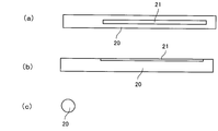
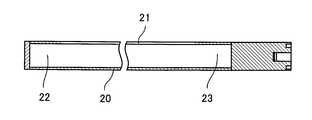
- the pouring pipe 20 forms a slit 21 along the length direction. Since the slit 21 does not extend to the end of the pouring pipe 20, the bag portions 22 and 23 having different volumes are formed at both ends of the pouring pipe 20.
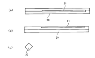
- the pouring pipe 20 is not limited to a cylindrical shape, and may be a square cylindrical shape. Further, even in the case of the rectangular tube shape, the position where the slit 21 is formed may be either a flat portion as shown in FIG. 4 or a corner portion as shown in FIG.
- the robot 30 has a crank 32 at the tip of an articulated arm 31, and the pouring pipe 20 is attached to one end of the crank 32 in a cantilever state.
- the articulated arm 31 can support the pouring pipe 20 at any position and posture within a predetermined range, and the crank 32 is rotatable around the axis of the tip arm of the articulated arm 31 and is within the predetermined range.
- the pouring ladle 20 can be supported at any position and posture, and a holding furnace 40 for the molten metal is also disposed within the range where the articulated arm 31 can reach.
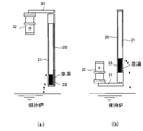
- the one end side or the other end side of the pouring ladle 20 is dipped downward in the holding furnace 40. After raising the pouring ladle 20 from the molten metal surface, the molten ladle 20 is vertically made to accurately cut out the molten metal in one of the bag portions 22 or 23.
- Cutting out the pouring ladle 20 vertically is simpler and more accurate than controlling the amount of molten metal cut out by the inclination angle of the pouring ladle 20.
- the pouring ladle 20 does not necessarily have to be vertical, and it is also possible to leave a predetermined amount of molten metal in the pouring ladle 20 while being inclined at a predetermined angle.
- the robot 30 is operated to immerse the pouring pipe 20 in the molten metal holding furnace 50.
- the molten metal holding furnace 50 for example, an Al-Si-based molten metal is stored, and when the pouring pipe 20 is immersed, the molten metal is filled in the pouring pipe 20 through the slit 21.
- the quantity of the molten metal with which the inside of the pouring pipe 20 is filled is adjusted with the immersion depth in the molten metal at the time of making the pouring pipe 20 incline or making a perpendicular state.
- the pouring pipe 20 is taken out from the molten metal holding furnace 50 with the slit 21 directed upward, and moves to the vicinity of the cylindrical mold 10.
- a mold release material is applied to the inner surface of the cylindrical mold 10 in advance.
- the axis of the pouring pipe 20 is made to coincide with the axis of the cylindrical mold 10, and in this state, the pouring pipe 20 is advanced into the rotating cylindrical mold 10 along the axis.
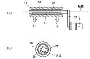
- This state is shown in FIGS. 6 (a) and 6 (b). That is, the molten metal is held in the pouring pipe 20 because the slit 21 faces upward while the pouring pipe 20 is in the cylindrical mold 10 so as not to interfere with the cylindrical mold 10. .
- the pouring pipe 20 is rotated about its axis so that the position of the pouring pipe 20 in the cylindrical mold 10 is not changed. Specifically, as shown in FIGS. 7A and 7B, the articulated arm 31 of the robot 30 is moved so that the crank 32 rotates about the axis of the pouring pipe 20.
- the slit 21 of the pouring pipe 20 is turned upside down in the cylindrical mold 10, and the molten metal held in the pouring pipe 20 is supplied from the slit 21 into the cylindrical mold 10.
- the molten metal for the entire length of the product is supplied at once into the cylindrical mold 10 and the supplied molten metal is centrifugally It is pressed against the inner circumferential surface and solidified to form a product such as a cylinder sleeve.
- the casting conditions at each part along the length direction become the same, and high quality products can be cast.
- Table 1 shows the case where pouring is performed simultaneously over the entire length of the mold using the pouring pipe according to the present invention, and pouring is performed only from one end of the mold using a conventional short pouring pipe.
- Mold material SNCM439 Mold length: 600 mm Mold temperature at pouring: 190 ° C
- the target product thickness is 5.5mm ⁇ 0.5mm except for hot water around.
- the robot 30 is operated to immerse the pouring ladle 20 in the molten metal holding furnace 50, and as shown in FIG. 8A, the molten metal (for example, Al—Si system) is put into the bag portion 22.
- the molten metal for example, Al—Si system
- the pouring ladle 20 is moved to the vicinity of the cylindrical mold 10 with the slit 21 directed upward.
- a moldable material is applied to the inner surface of the cylindrical mold 10 in advance.
- the insertion direction (axis line) of the pouring ladle 20 is made to coincide with the axis (rotation center) of the cylindrical mold 10, and the inside of the cylindrical mold 10 is rotating the pouring ladle 20 along the axis.
- the molten metal is held in the pouring ladle 20 since the slit 21 faces upward with the pouring ladle 20 entering the cylindrical mold 10.
- the pouring ladle 20 is rotated about its axis so as not to change the position of the pouring ladle 20 in the cylindrical mold 10. Then, as shown in FIG. 7, the slit 21 of the pouring ladle 20 is turned upside down in the cylindrical mold 10, and the molten metal held in the pouring ladle 20 is cut from the slit 21 into the cylindrical mold 10. Supplied inside.
- the molten metal for the entire length of the product is supplied at once into the cylindrical mold 10 and the supplied molten metal is centrifugally It is pressed against the inner circumferential surface and solidified to form an outer layer.
- the casting conditions at each part along the length direction become the same, and high quality products can be cast.
- the pouring ladle 20 is retracted from the cylindrical mold 10, and the pouring ladle 20 is moved again to the position of the holding furnace 40, and this time, as shown in FIG. 8 (b), the pouring ladle The other end of 20 is immersed in the holding furnace 40 of the molten metal, and the molten metal (for example, Al-Si system) is put into the bag portion 23.
- the molten metal for example, Al-Si system
- the pouring ladle 20 is advanced into the cylindrical mold 10 and rotated about the axis to turn the slit 21 downward as described above, and the molten metal in the pouring ladle 20 is already formed by the outer layer.
- the inner side surface of the cylindrical mold 10 being fed is formed, and the inner layer is formed inside the outer layer, and a double pipe is cast.
- the mold-forming material is applied to the inner surface of the mold in advance, so the double pipe can be easily taken out.
- the centrifugal casting apparatus includes a cylindrical mold 10, a robot 30 that moves the pouring pipe 20 and the pouring pipe 20, and a measuring device 40 that measures the dripping of the pouring pipe 20.
- a robot 30 that moves the pouring pipe 20 and the pouring pipe 20
- a measuring device 40 that measures the dripping of the pouring pipe 20.
- FIG. 9 in order to make the dripping of the pouring pipe 20 intelligible, it exaggerates and draws.
- the cylindrical mold 10 is supported on the pair of front and rear rollers 11 with the shaft substantially horizontal.
- the rollers 11 are fitted in grooves 12 formed in the circumferential direction of the cylindrical mold 10 to prevent the cylindrical mold 10 from moving in the axial direction during rotation.
- At least one of the four rollers 11 is a drive roller which is rotated by a motor, and the other is a driven roller.
- End plates 13 are attached to both ends of the cylindrical mold 10, and the pouring pipe 20 can be inserted into and removed from the cylindrical mold 10 through an opening formed in one of the end plates. Further, a slit 21 is formed in the pouring pipe 20 along the length direction, and this slit 21 is for the molten metal to flow in and out in the pouring pipe 20, and the length is the length of the product to be cast It is set approximately equal to.
- the robot 30 has a crank 32 at the tip of an articulated arm 31, and the pouring pipe 20 is attached to one end of the crank 32 in a cantilever state.
- the articulated arm 31 can support the pouring pipe 20 at an arbitrary position and posture within a predetermined range, and the crank 32 is rotatable around the axis of the tip arm of the articulated arm 31.
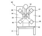
- pillars 44 and 45 are erected on both sides of the pouring pipe 20, and light emitting elements 46 and 47 for emitting band-like green laser light are attached to the upper portions of the pillars 44 and 45; At the lower part of 45, light receiving elements 48 and 49 for receiving the laser light are attached.
- the strip laser light emitted from the light emitting element 46 and received by the light receiving element 48 and the strip laser light emitted from the light emitting element 47 and received by the light receiving element 49 are in a plane orthogonal to the axis of the pouring pipe 20 Cross at 90 °. And, assuming that no sag occurs, the axis line of the pouring pipe 20 is set to coincide with the center of the square detection area formed by the intersection, as shown in FIG.
- the center of the detection area and the axis of the pouring pipe 20 are separated, and the light quantity blocked by the pouring pipe 20 decreases.
- the amount of light received at 48 and 49 increases.
- the position of the axis of the pouring pipe 20 can be known by distributing the amount of increase in the amount of light received to the X-direction component and the Y-direction component.
- the robot 30 is operated to immerse the pouring pipe 20 in a molten metal holding furnace (not shown).
- a molten metal holding furnace for example, an Al—Si-based molten metal is stored, and when the pouring pipe 20 is immersed, the molten metal is filled in the pouring pipe 20 through the slit 21.
- the quantity of the molten metal with which the inside of the pouring pipe 20 is filled is adjusted with the immersion depth in the molten metal at the time of making the pouring pipe 20 incline or making a perpendicular state.
- the pouring pipe 20 is taken out with the slit 21 directed upward from the molten metal holding furnace, moved to the vicinity of the cylindrical mold 10, and the insertion of the pouring pipe 20 The direction is made to coincide with the axis (rotation center) of the cylindrical mold 10.
- the maximum drooping amount or the entire shape of the pouring pipe 20 is measured using the above-described measuring device 40, and the inclination of the pouring pipe 20 is adjusted in accordance with the measurement result.
- the articulated arm 31 is operated so that the tip of the pouring tube 20 is directed slightly upward, and in this state, the pouring tube 20 is rotated along the axis. Then, they are introduced into the cylindrical mold 10.
- the molten metal is held in the pouring pipe 20 because the slit 21 faces upward as shown in FIG. 6 in a state where the pouring pipe 20 is in the cylindrical mold 10.
- the pouring pipe 20 is rotated about its axis so as not to change the position of the pouring pipe 20 in the cylindrical mold 10.
- the articulated arm 31 of the robot 30 is moved so that the crank 32 rotates around the axis of the pouring pipe 20.
- the slit 21 of the pouring pipe 20 is turned upside down in the cylindrical mold 10, and the molten metal held in the pouring pipe 20 is supplied from the slit 21 into the cylindrical mold 10.
- the molten metal for the entire length of the product is supplied at once into the cylindrical mold 10 and the supplied molten metal is centrifugally It is pressed against the inner circumferential surface and solidified to form a product such as a cylinder sleeve.
- the casting conditions at each part along the length direction become the same, and high quality products can be cast.
- an apparatus for causing the strip laser light to cross is shown as the measuring apparatus 40, but the invention is not limited to this.
- the slit 21 was shown as a pouring spout formed in the pouring pipe 20 as an Example, what provided the pouring spout at the front-end may be used.
- the center of the detection area and the axis of the pouring pipe 20 are separated, and the light quantity blocked by the pouring pipe 20 decreases.
- the amount of light received at 48 and 49 increases.
- the position of the axis of the pouring pipe 20 can be known by distributing the amount of increase in the amount of light received to the X-direction component and the Y-direction component.
- FIG. 12 is a schematic view showing the relationship between the axis of the pouring pipe before insertion and the axis (rotation center) of the cylindrical mold, and the reference numerals are as follows.
- P1 Base end of pouring pipe (support part)
- Pn the tip of the pouring pipe
- y1 to yn Y direction (longitudinal direction) position d1 to dn ...
- Z direction vertical direction
- the amount of sagging Y axis ... axis line ⁇ of the cylindrical mold ... the angle between the axis connecting the line connecting the base end and the tip of the pouring pipe and the axis
- the above ⁇ can be obtained by the following equation (1)
- the pouring pipe is curved so that the middle part bulges upward. Even if the proximal end P1 and the distal end Pn are aligned with the axis of the cylindrical mold, if the amount of upward bending (D) is large, it can not be inserted into the cylindrical mold.
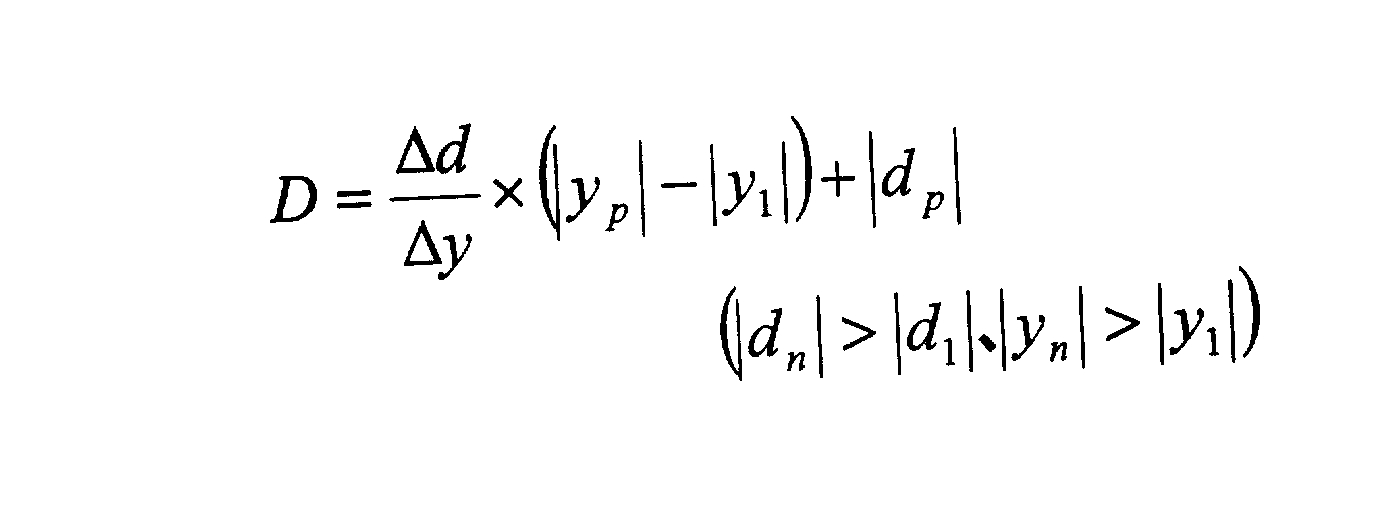
- the amount of curvature (D) is obtained by the following (Equation 2).
- the articulated arm 31 is operated to move the proximal end of the pouring pipe up and down by the distance d1 to make the proximal end a cylindrical mold.
- the tip of the pouring pipe is moved up and down by the distance dn to align the tip with the axis of the cylindrical mold.
- the pouring pipe may be moved upward by a distance d1 while lifting the tip of the pouring pipe first.
- the maximum value (D) of the amount of bending is determined. If it is less than the difference (C) between the opening diameter of 13 and the outside diameter of the pouring tube, the pouring tube 20 is inserted into the cylindrical mold 10, and the maximum value (D) of the amount of bending is the end plate If the difference (C) between the opening diameter of 13 and the outer diameter of the pouring pipe is greater than (C), the pouring operation is stopped, and after a while, the pouring pipe is again poured or the pouring pipe 20 is replaced.
- the articulated arm 31 is operated to cause the pouring pipe 20 to enter the rotating cylindrical mold 10 along the axis of the cylindrical mold. .
- the molten metal of the entire length of the product is supplied at once into the cylindrical mold 10, and the supplied molten metal is centrifugally generated on the inner peripheral surface of the mold 10. And solidify into a product such as a cylinder sleeve.
- the centrifugal casting apparatus provided with the pouring pipe according to the present invention can be applied to casting of a cylinder sleeve made of an Al-Si based material.
Landscapes
- Engineering & Computer Science (AREA)
- Mechanical Engineering (AREA)
- Casting Support Devices, Ladles, And Melt Control Thereby (AREA)
Abstract
【課題】 遠心鋳造装置の円筒状金型内の全長に亘って同時に溶湯を供給できる注湯管を提供する。 【解決手段】 溶湯を充填した注湯管20を円筒状金型10内に進入させ、 次いで、注湯管20の円筒状金型10内での位置を変えないように注湯管20を軸廻りに回転させてスリット21を上下反転させ、注湯管20内に保持されている溶湯をスリット21から円筒状金型10内に供給する。
Description
本発明は、遠心鋳造用注湯管(ラドル)または注湯取鍋とこの注湯管または注湯取鍋を用いた遠心鋳造装置および遠心鋳造法に関する。
エンジンのボア内に配設されるシリンダスリーブなどの鋳造法として、遠心鋳造法が知られている。
この遠心鋳造法は高速で回転する円筒状金型内に注湯管を介して溶湯を注入し、遠心力によって溶湯を円筒状金型内面に押し付けて成形する鋳造法である。
この遠心鋳造法は高速で回転する円筒状金型内に注湯管を介して溶湯を注入し、遠心力によって溶湯を円筒状金型内面に押し付けて成形する鋳造法である。
遠心鋳造法は円筒状金型を水平方向に配置するのが一般的である。そして、水平方向に配置した円筒状金型内に一端から溶湯を供給すると、Al合金などは凝固速度が速いため、他端まで溶湯が十分に届かないことが生じる。このため水平方向に配置した円筒状金型内に溶湯を供給する注湯管として長尺のものを用い、円筒状金型内の奥まで注湯口が届くようにした先行技術として、特許文献1~3が知られている。
特許文献1,2には、長尺な注湯管の先端部と中間部に挟持板を取り付け、これら挟持板間に注湯管が貫通する貫通支持板を設け、前記注湯管を囲むように挟持板および貫通支持板に4本の棒状ヒータを注湯管と平行に貫通支持させた構造が開示されている。
また特許文献2には、取鍋内の溶湯を鋳型に注湯する際に、注湯開始から完了までの間の取鍋の注湯傾斜角度データ及びその間に取鍋が鋳型に接近移動する距離データを予め設定し、該設定された角度データ及び距離データに基づいて取鍋内の溶湯を前記鋳型に注湯することが開示されている。
また特許文献2及び特許文献3では、水平方向に配置した円筒状金型内に溶湯を供給する手段として、注湯管を水平方向から円筒状金型内に挿入し、この注湯管に取鍋(特許文献2ではポット、特許文献3ではサイロ)を介して一定量の溶湯を供給するようにしている。
また特許文献3には、遠心鋳造法によって二層管を鋳造するにあたり、長尺な注湯管の型内挿入部の外周部にヒータを取り付けるとともに溶湯の内側表面温度を測定する温度計を注湯管に設けた構造が提案されている。
特許文献4及び特許文献5には、金型内への溶湯の供給量は注湯管(取鍋)の傾斜角によって制御する内容が開示されている。例えば、特許文献4には、溶湯を所定の状態に保持する保持炉から所定量の溶湯を取鍋装置に分け、この取鍋装置から昇温炉装置に溶湯を受け入れ、傾動装置によって昇温炉装置を傾けることで所定量の溶湯を切り出して金型に注湯することが記載されている。
特許文献6には注湯管(トラフ)を移動させずに金型を載せている台車を移動させることで、注湯管から注がれる溶湯の量を金型の長さ方向に沿って均一にするようにしている。
上述した長尺の注湯管を用いることで、注湯口を円筒状金型内の奥まで差し込むことができるので、注湯管を円筒状金型の軸方向に移動させつつ注湯すれば、円筒状金型内で軸方向に沿って満遍なく注湯できる。
しかしながら、従来の長尺注湯管は先端を注湯口としているため、円筒状金型の製品となる部分に同時に注湯することはできず、そのため、凝固時間などの凝固条件が部分的に異なり、また注湯量が軸方向に沿って均一にならず、製品の厚みが軸方向において変化することが考えられ、仕上げ加工における研削量が多くなる。
また、従来の長尺注湯管にあっては注湯管を移動しながら金型内に注湯することになるので、時間がかかり、タクトタイムを短縮することができない。
また鋳造製品の肉厚は注湯量に比例する。例えば、遠心鋳造法によって鋳造される製品は鋳鉄管やアルミ合金製のシリンダスリーブであり、これらには正確な肉厚が要求される。遠心鋳造法の場合、製品の肉厚は溶湯の供給量によって決定されるため、取鍋から注湯管に供給される溶湯量は各ショット毎に同じであることが要求されるが、微細なコントロールを取鍋の傾斜角によって行うことは難しく、製品の厚みにバラツキが生じ、後工程での研削量が多くなる。
特に、遠心鋳造法によってAl-Si系の二重管を作成する場合、最初に鋳造する外側層は内側層を鋳造する際のチラー(冷し金)の役目を担うため、薄肉であることが要求され、内側層は鋳造後に研削を行うため所定の厚みが要求される。このような要求を満足するには正確な注湯量としなければならないが、現状では困難である。
また、長尺の注湯管は片持ち状態で支持され且つ溶湯は高温で重いため、先端が垂れてしまう。垂れの量が大きいと注湯管を円筒状金型内に挿入することができない。上述した特許文献1,2は注湯管の周囲を棒状ヒータで囲んでいるため、垂れの量は少ないが、全体の径が大きくなる不利がある。
特許文献3,6に開示される注湯管は細く長いが、注湯管の垂れについては何ら考慮されていない。特に垂れ量は注湯管の予熱条件や注湯温度によって各ショット毎に変化するため、予め垂れ量を決めておき、その量を補正して注湯することができない。
上記課題を解決すべく第1グループ(請求項1~3)に属する発明は、回転可能な円筒状金型内に溶湯を供給する注湯管の構成として、長さ方向に沿って溶湯の流入・流出が可能なスリットを形成した。
スリットの長さは鋳造する製品の長さとほぼ同程度とする。またスリットの幅については、余り狭いと溶湯の流入・流出に支障を来たし、逆に広すぎると移動の際にこぼれるおそれがあるので、これらを考慮して決定する。
また遠心鋳造装置として、回転可能な円筒状金型と、この円筒状金型内に溶湯を供給するためのスリットが長さ方向に沿って形成された注湯管と、この注湯管を前記円筒状金型内に挿抜せしめるとともに前記スリットの位置を上下反転させるために注湯管を軸回りに回転させるロボットとを備える構成とした。
円筒状金型は完全に水平でなく若干傾斜させて配置してもよい。またロボットとしては多関節ロボットを用いることで、溶湯の保持炉から注湯管で溶湯を掬って金型内に注湯管を挿抜させ且つ回転させる動作を容易に行うことができる。
更に遠心鋳造方法として、長さ方向に沿って溶湯の流入・流出が可能なスリットが形成された注湯管内に溶湯を入れ、注湯管のスリットを上方にするとともに軸線をほぼ水平状態に設置された円筒状金型の軸線に一致させ、注湯管を回転する円筒状金型内に軸線に沿って進入させ、前記スリットを形成した箇所が円筒状金型内に入った後に注湯管を軸回りに回転させてスリットを下方に向け、スリットから注湯管内に保持した溶湯を円筒状金型内に供給する構成とした。
また、上記課題を解決すべく第2グループ(請求項4~6)に属する発明は、回転可能な円筒状金型内に溶湯を供給する注湯取鍋であって、この注湯取鍋には両端部を残して長さ方向に沿って溶湯の流入・流出が可能なスリットが形成され、両端部には容積の異なる袋部が形成された構成である。なお、前記注湯取鍋としては例えば外径が管状をなすものが含まれる。
スリットの長さは鋳造する製品の長さとほぼ同程度とする。またスリットの幅については、あまり狭いと溶湯の流入・流出に支障を来たし、逆に広すぎると移動の際にこぼれるおそれがあるので、これらを考慮して決定する。また、袋部の容積は目的とする鋳造品の肉厚に応じて決定する。
上記の注湯取鍋は、遠心鋳造法によって二重管を鋳造する場合に特に有効である。
即ち、溶湯の保持炉に注湯取鍋の一端を浸漬して一端側の袋部に溶湯を充填し、注湯取鍋を水平状態でスリットが上になるようにして回転する円筒状金型内に進入させ、前記スリットを形成した箇所が円筒状金型内に入った後に注湯取鍋を軸回りに回転させてスリットを下方に向け、スリットから注湯取鍋内の溶湯を円筒状金型内に供給して外側層を鋳造し、次いで、注湯取鍋を円筒状金型から後退させた後、溶湯の保持炉に注湯取鍋の他端を浸漬して他端側の袋部に溶湯を充填し、注湯取鍋を水平状態でスリットが上になるようにして回転する円筒状金型内に進入させ、前記スリットを形成した箇所が円筒状金型内に入った後に注湯取鍋を軸回りに回転させてスリットを下方に向け、スリットから注湯取鍋内の溶湯を円筒状金型内に供給して前記外側層の内側に内側層を鋳造する。
即ち、溶湯の保持炉に注湯取鍋の一端を浸漬して一端側の袋部に溶湯を充填し、注湯取鍋を水平状態でスリットが上になるようにして回転する円筒状金型内に進入させ、前記スリットを形成した箇所が円筒状金型内に入った後に注湯取鍋を軸回りに回転させてスリットを下方に向け、スリットから注湯取鍋内の溶湯を円筒状金型内に供給して外側層を鋳造し、次いで、注湯取鍋を円筒状金型から後退させた後、溶湯の保持炉に注湯取鍋の他端を浸漬して他端側の袋部に溶湯を充填し、注湯取鍋を水平状態でスリットが上になるようにして回転する円筒状金型内に進入させ、前記スリットを形成した箇所が円筒状金型内に入った後に注湯取鍋を軸回りに回転させてスリットを下方に向け、スリットから注湯取鍋内の溶湯を円筒状金型内に供給して前記外側層の内側に内側層を鋳造する。
上記の遠心鋳造法において、注湯取鍋を溶湯の保持炉に浸漬する角度は水平でもまた斜めでよいが、保持炉から引き上げた後に保持炉内でほぼ垂直とすることで、正確に一定の注湯量を掬うことができる。尚、引き上げた後に傾斜角度を決めて所定量の溶湯を注湯取鍋内に残すようにしてもよい。
また上記課題を解決すべく第3グループ(請求項7~9)に属する発明は、円筒状金型内に挿入して注湯を行う注湯管の垂れ量を測定し、この測定結果に基づいて注湯管の挿入角度を補正した後、注湯管を円筒状金型内に挿入して注湯管から溶湯を供給するようにした。
尚、円筒状金型内に注湯管を挿入するには、注湯管の挿入方向をほぼ水平状態に設置された円筒状金型の軸線に一致させる必要があるが、この一致させる時期は注湯管の垂れ量を測定する前後のいずれでもよい。ただし、測定する前に軸線に一致させておけば、測定後速やかに注湯管を挿入することができるので正確性が向上する。
前記注湯管としては、先端に注湯口を設けたものでもよいが、長さ方向に沿って溶湯の流入・流出が可能なスリットが形成された注湯管とすることが、凝固速度が速いAl-Si系溶湯の場合に特に好ましい。即ち、この場合には前記スリットを上にした状態で円筒状金型内に挿入し、この後、注湯管を軸周りに回転させて前記スリットを下に向けることで注湯管内の溶湯を円筒状金型の長さ方向に沿って同時に供給することができる。その結果溶湯を急冷して微細なSi結晶を形成することが可能になり、耐磨耗性を大幅に向上することができる。
また、前記注湯管の垂れ量の測定手段としては、カメラ画像の解析も考えられるが、赤熱する物体を測定する場合、画像の輪郭が不鮮明になることがあるので、例えば、90°向きが異なる2つの帯状レーザ光を注湯管に照射することが好ましい。この場合、2つの帯状レーザ光は交差させてもよいし、前後方向に離してもよい。なお、測定に用いられるレーザ光としては測定対象物が赤熱しているので緑色レーザ光が適している。
更に、前記2つの帯状レーザ光の発光装置としては、注湯管の長さ方向に沿って移動するフレームに取り付けることが考えられる。斯かる構成とすることで、注湯管の垂れ量だけでなく、注湯管の全体形状も測定することができる。
また、上記課題を解決すべく第4グループ(請求項10~11)に属する発明は、円筒状金型内に挿入して注湯を行う注湯管の挿入方向を、ほぼ水平状態に設置された円筒状金型の軸線(回転中心)に一致させ、この状態で注湯管の基端部(支持部)と先端部の位置を検出し、前記基端部と先端部が円筒状金型の軸線と一致するように注湯管の角度調整を行い、更に角度調整後の注湯管の基端部と先端部の中間箇所における前記軸線からのオフセット量の最大値が円筒状金型の開口直径と断面円形の注湯管外形直径との差未満である場合に円筒状金型内に注湯管を挿入するようにした。
前記オフセット量の最大値が円筒状金型の開口直径と断面円形の注湯管外形直径との差以上と判定された場合には、鋳造を中断して所定時間おいてから再度鋳造を開始するか、注湯管を交換する。
前記注湯管の形状、注湯管の垂れ量の測定手段については第3グループと同様である。注湯管を円筒状金型に挿入する際には円筒状金型の軸線からのオフセット量の最大値が小さくなるように注湯管を円筒状金型の軸線に対して平行に移動させる。このようにすれば注湯管を円筒状金型の開口部に干渉することなく挿入することができる。
第1グループの発明によれば、注湯管の構造として長さ方向に溶湯の流入・流出が可能なスリットが形成されたものとしたので、遠心鋳造の円筒状金型内の全長方向に、同時に溶湯を供給することができるので、鋳造品の全長に亘って凝固条件を同じにすることができる。その結果、高品質の鋳造品を得ることができる。
注湯管の先端を注湯口としたもので、円筒状金型内の全長方向に注湯するには注湯管を軸方向に移動させつつ注湯する必要がある。その結果、注湯に時間がかかるが、第1グループの発明によれば、同時に全長方向に注湯することができるので、タクトタイムも短縮することができる。
第2グループの発明によれば、両端部に袋部を有するので、各ショット毎に正確な量の溶湯を金型に供給することができる。またスリットを介して、円筒状金型内の全長方向に同時に溶湯を供給することができるので、鋳造品の全長に亘って凝固条件を同じにすることができる。その結果、高品質の鋳造品を得ることができる。
また、第2グループの発明によれば、遠心鋳造法によって二重管を鋳造する場合に、外側層及び内側層とも正確な肉厚の鋳造品を得ることができ、特に外側層の厚みを均一で薄くできるので、内側層を急冷することがでる。したがって、溶湯としてAl-Si系を使用した場合、Siの均一で微細な結晶が得られ、耐摩耗性に優れた製品とすることができる。
第3グループの発明によれば、注湯管を遠心鋳造用の金型内に挿入する直前に注湯管の垂れ量を測定するため、注湯管の予熱条件や注湯温度に拘らず、各ショット毎に正確に注湯管の垂れ量を知ることができる。
そして、その測定結果に基づいて、注湯管の円筒状金型への挿入角度を補正するため、確実に注湯管を円筒状金型へ挿入することができる。
そして、その測定結果に基づいて、注湯管の円筒状金型への挿入角度を補正するため、確実に注湯管を円筒状金型へ挿入することができる。
第4グループの発明によれば、各ショット毎に鋳造の直前に正確に注湯管の変形量(垂れ量)を測定し、その変形量を見込んで注湯管の挿入角度および位置を補正するため、金型との干渉なく遠心鋳造を行うことができ、また、干渉することが予想される場合には予め対処することができるので、全体の作業効率が向上する。
また、第3及び第4グループの発明によれば、注湯管の長さ方向に溶湯の流入・流出を行うためのスリットを形成することで、遠心鋳造の円筒状金型内の全長方向に、同時に溶湯を供給することができ、鋳造品の全長に亘って凝固条件を同じにすることができる。その結果、高品質の鋳造品を得ることができる。
以下に第1及び第2グループに属する発明の実施の形態を添付図面に基づいて説明する。図1に示すように遠心鋳造装置は、円筒状金型10、注湯管20及び注湯管(注湯取鍋)20を移動させるロボット30を備える。
円筒状金型10は軸を略水平状態として前後の対をなすローラ11…上に支持されている。ローラ11…は円筒状金型10の周方向に形成した溝12に嵌り込むことで回転中に円筒状金型10が軸方向に移動するのを阻止している。
また、4つのローラ11…のうち少なくとも1つがモータによって回転する駆動ローラで残りは被動ローラとされている。
円筒状金型10は両端に端板13,13を取り付け、一方の端板に形成した開口を介して前記注湯管20が円筒状金型10内に挿抜可能とされている。
図2(a)~(c)及び図3に示すように、注湯管20は長さ方向に沿ってスリット21を形成している。このスリット21は注湯管20の端部までは延びていないため、注湯管20の両端部には異なる容積の袋部22,23が形成される。
また、図4(a)~(c)及び図5(a)~(c)に示すように、注湯管20としては円筒形に限らず角筒形でもよい。また角筒形とした場合でもスリット21を形成する位置は、図4に示すような平面部、図5に示すようなコーナ部のどちらでもよい。
ロボット30は多関節アーム31の先端にクランク32を有し、このクランク32の一端に前記注湯管20を片持ち状態で取り付けている。多関節アーム31は所定の範囲内で任意の位置および姿勢で注湯管20を支持することができ、クランク32は多関節アーム31の先端アームの軸廻りに回転可能とされ、所定の範囲内で任意の位置および姿勢で注湯取鍋20を支持することができ、多関節アーム31が届く範囲に溶湯の保持炉40も配置されている。
前記多関節アーム31及びクランク32を操作することで、図8(a)及び(b)に示すように、注湯取鍋20の一端側又は他端側を下にして保持炉40内に浸漬され、この後注湯取鍋20を溶湯面から引き上げた後に、注湯取鍋20を垂直にすることで、袋部22または23の一方に溶湯が正確に切り出される。
注湯取鍋20を垂直にして切り出す方が注湯取鍋20の傾斜角度によって溶湯の切り出し量を制御する場合よりも簡単で正確である。尚、要求される溶湯の量によっては、必ずしも注湯取鍋20を垂直にする必要はなく、所定角度傾けた状態で所定量の溶湯を注湯取鍋20内に残すことも可能である。
以上において、遠心鋳造を行うには、先ずロボット30を操作して、注湯管20を溶湯保持炉50内に浸漬する。この溶湯保持炉50内には例えばAl-Si系の溶湯が貯留されており、注湯管20を浸漬するとスリット21を介して溶湯が注湯管20内に充填される。尚、注湯管20内に充填する溶湯の量は注湯管20を傾斜させること或いは垂直状態とした際の溶湯内への浸漬深さで調整する。
注湯管20内に溶湯を充填したならば、溶湯保持炉50からスリット21を上に向けた状態で注湯管20を取り出し、円筒状金型10の近傍まで移動する。尚、円筒状金型10の内面には予め離型材が塗布されている。
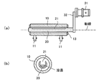
そして、注湯管20の軸線を円筒状金型10の軸線と一致させ、その状態で軸線に沿って注湯管20を回転している円筒状金型10内に進入させる。この状態を図6(a)および(b)で示している。即ち、注湯管20は円筒状金型10と干渉しないように円筒状金型10内に入った状態でスリット21は上方を向いているため、溶湯は注湯管20内に保持されている。
次いで、注湯管20の円筒状金型10内での位置を変えないように注湯管20を軸廻りに回転させる。具体的には、図7(a)および(b)に示すように、注湯管20の軸を中心としてクランク32が回転するようにロボット30の多関節アーム31を移動させる。
すると、円筒状金型10内で注湯管20のスリット21が上下反転し、注湯管20内に保持されていた溶湯はスリット21から円筒状金型10内に供給される。
スリット21の長さは鋳造する製品の長さと略等しく設定しているため、製品の全長分の溶湯が一気に円筒状金型10内に供給され、供給された溶湯は遠心力によって金型10の内周面に押し付けられ、凝固してシリンダスリーブなどの製品となる。
このように、製品の全長に沿って同時に溶湯が供給されることで、長さ方向に沿った各部における鋳造条件が同じになり、高品質の製品を鋳造することができる。
溶湯が凝固した後は予め金型内面に塗型材が塗布されているため、容易に取り出すことができる。
尚、実施例としては注湯管の溶湯保持炉への浸漬から、円筒状金型に対する挿抜までを1つの多関節ロボットで行う例を示したが、円筒状金型に対する挿抜と他の動作を個別の装置に分担させることもできる。また注湯を2回に分けて行うことで2層管を作製することも可能である。
以下の(表1)は本発明に係る注湯管を用いて金型の全長に亘って同時に注湯した場合と、従来の短尺の注湯管を用いて金型の一端からのみ注湯した場合の製品肉厚を比較したもので、以下の条件で判定した。
金型材:SNCM439
金型長さ:600mm
注湯時金型温度:190℃
型内塗型材:アセチレンスモーク
溶湯:AC9A
注湯温度:800℃
狙い製品肉厚5.5mm±0.5mm以外は湯廻りNGとする。
金型材:SNCM439
金型長さ:600mm
注湯時金型温度:190℃
型内塗型材:アセチレンスモーク
溶湯:AC9A
注湯温度:800℃
狙い製品肉厚5.5mm±0.5mm以外は湯廻りNGとする。

上記(表1)から本発明に係る注湯管を用いることで、均一な肉厚の製品が得られることが分かる。
次に、遠心鋳造法によって二重管の鋳造を行う手順を説明する。先ずロボット30を操作して、注湯取鍋20を溶湯保持炉50内に浸漬して、図8(a)に示すように、袋部22に溶湯(例えばAl-Si系)を入れる。
注湯取鍋20内に溶湯を充填したならば、スリット21を上に向けた水平状態で注湯取鍋20を円筒状金型10の近傍まで移動する。尚、円筒状金型10の内面には予め塗型材が塗布されている。
そして、注湯取鍋20の挿入方向(軸線)を円筒状金型10の軸線(回転中心)に一致させ、そのまま軸線に沿って注湯取鍋20を回転している円筒状金型10内に進入させる。図6に示したように、注湯取鍋20が円筒状金型10内に進入した状態でスリット21は上方を向いているため、溶湯は注湯取鍋20内に保持されている。
次いで、注湯取鍋20の円筒状金型10内での位置を変えないように注湯取鍋20を軸廻りに回転させる。すると、図7に示すように、円筒状金型10内で注湯取鍋20のスリット21が上下反転し、注湯取鍋20内に保持されていた溶湯はスリット21から円筒状金型10内に供給される。
スリット21の長さは鋳造する製品の長さと略等しく設定しているため、製品の全長分の溶湯が一気に円筒状金型10内に供給され、供給された溶湯は遠心力によって金型10の内周面に押し付けられ、凝固して外側層が形成される。このように、製品の全長に沿って同時に溶湯が供給されることで、長さ方向に沿った各部における鋳造条件が同じになり、高品質の製品を鋳造することができる。
この後、注湯取鍋20を円筒状金型10から後退させ、再び注湯取鍋20を保持炉40の位置まで移動し、今度は図8(b)に示すように、注湯取鍋20の他端を溶湯の保持炉40内に浸漬して袋部23に溶湯(例えばAl-Si系)を入れる。
この後は前記と同様に、注湯取鍋20を円筒状金型10内に進入させ、軸周りに回転させてスリット21を下向きとし、注湯取鍋20内の溶湯を既に外側層が形成されている円筒状金型10内側面に供給し、外側層の内側に内側層を形成し二重管が鋳造される。
溶湯が凝固した後は予め金型内面に塗型材が塗布されているため、容易に二重管を取り出すことができる。
次に第3及び第4グループに属する発明の実施の形態を添付図面に基づいて説明する。図9に示すように遠心鋳造装置は、円筒状金型10、注湯管20及び注湯管20を移動させるロボット30、注湯管20の垂れを測定する測定装置40を備える。尚、図9では注湯管20の垂れを分かりやすくするため誇張して描いている。
円筒状金型10は軸を略水平状態として前後の対をなすローラ11…上に支持されている。ローラ11…は円筒状金型10の周方向に形成した溝12に嵌り込むことで回転中に円筒状金型10が軸方向に移動するのを阻止している。
また、4つのローラ11…のうち少なくとも1つがモータによって回転する駆動ローラで残りは被動ローラとされている。
円筒状金型10は両端に端板13,13を取り付け、一方の端板に形成した開口を介して前記注湯管20が円筒状金型10内に挿抜可能とされている。また注湯管20には長さ方向に沿ってスリット21が形成され、このスリット21は注湯管20内に溶湯が流入・流出するためのもので、その長さは鋳造する製品の長さに略等しく設定している。
ロボット30は多関節アーム31の先端にクランク32を有し、このクランク32の一端に前記注湯管20を片持ち状態で取り付けている。多関節アーム31は所定の範囲内で任意の位置および姿勢で注湯管20を支持することができ、クランク32は多関節アーム31の先端アームの軸廻りに回転可能とされている。
測定装置40は基台41にレール42を設け、このレール42に筒状金型10内に挿入される直前で待機状態にある注湯管20に沿って往復動するフレーム43を係合している。
フレーム43は注湯管20を挟んで両側に柱部44,45が起立し、柱部44,45の上部には帯状の緑色レーザ光を発する発光素子46,47が取り付けられ、柱部44,45の下部には前記レーザ光を受光する受光素子48,49が取り付けられている。
発光素子46から発せられて受光素子48で受光される帯状レーザ光と、発光素子47から発せられて受光素子49で受光される帯状レーザ光とは注湯管20の軸線と直交する面内で90°で交差している。そして垂れが生じていないと仮定した場合の注湯管20の軸線が、図10に示すように、交差することによって形成される四角い検出領域の中心に一致するように設定する。
一方、図11に示すように注湯管20が自重によって垂れていると、検出領域の中心と注湯管20の軸線とが離れ、注湯管20によって遮断される光量が少なくなり、受光素子48、49での受光量が増加する。この受光量の増加分をX方向成分とY方向成分に振り分けることで、注湯管20の軸線の位置を知ることができる。
更にフレーム43を注湯管20に沿って移動しつつ各測定位置での軸線の位置を知ることで自重で曲がっている注湯管20の全体形状を知ることができる。
以上において、遠心鋳造を行うには、先ずロボット30を操作して、注湯管20を図示しない溶湯保持炉内に浸漬する。この溶湯保持炉内には例えばAl-Si系の溶湯が貯留されており、注湯管20を浸漬するとスリット21を介して溶湯が注湯管20内に充填される。尚、注湯管20内に充填する溶湯の量は注湯管20を傾斜させること或いは垂直状態とした際の溶湯内への浸漬深さで調整する。
注湯管20内に溶湯を充填したならば、溶湯保持炉からスリット21を上に向けた状態で注湯管20を取り出し、円筒状金型10の近傍まで移動し、注湯管20の挿入方向を円筒状金型10の軸線(回転中心)に一致させる。
この状態から前記した測定装置40を用いて、注湯管20の最大垂れ量若しくは全体形状を測定し、測定結果に合わせて、注湯管20の傾きを調整する。例えば、注湯管20の先端が垂れている場合は、多関節アーム31を操作して注湯管20の先端が若干上を向くようにし、この状態で軸線に沿って注湯管20を回転している円筒状金型10内に進入させる。
円筒状金型10内に注湯管20が入った状態でスリット21は、図6に示すように上方を向いているため、溶湯は注湯管20内に保持されている。次いで、図7に示すように、注湯管20の円筒状金型10内での位置を変えないように注湯管20を軸廻りに回転させる。具体的には、注湯管20の軸を中心としてクランク32が回転するようにロボット30の多関節アーム31を移動させる。
すると、円筒状金型10内で注湯管20のスリット21が上下反転し、注湯管20内に保持されていた溶湯はスリット21から円筒状金型10内に供給される。
スリット21の長さは鋳造する製品の長さと略等しく設定しているため、製品の全長分の溶湯が一気に円筒状金型10内に供給され、供給された溶湯は遠心力によって金型10の内周面に押し付けられ、凝固してシリンダスリーブなどの製品となる。
このように、製品の全長に沿って同時に溶湯が供給されることで、長さ方向に沿った各部における鋳造条件が同じになり、高品質の製品を鋳造することができる。
溶湯が凝固した後は予め金型内面に塗型材が塗布されているため、容易に取り出すことができる。
尚、実施例としては測定装置40として、帯状レーザ光を交差させる装置を示したが、これに限定されるものではない。また、実施例としては注湯管20に形成する注湯口としてスリット21を示したが、先端に注湯口を設けたものでもよい。
ところで、図11に示すように注湯管20が自重によって垂れていると、検出領域の中心と注湯管20の軸線とが離れ、注湯管20によって遮断される光量が少なくなり、受光素子48、49での受光量が増加する。この受光量の増加分をX方向成分とY方向成分に振り分けることで、注湯管20の軸線の位置を知ることができる。
更にフレーム43を注湯管20に沿って移動しつつ各測定位置での軸線の位置を知ることで自重で曲がっている注湯管20の全体形状を知ることができる。
次に、図12~図15に基づき、注湯管を円筒状金型に干渉なく挿入するための挿入姿勢の調整について説明する。
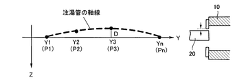
まず図12は挿入前の注湯管の軸線と円筒状金型の軸線(回転中心)との関係を示す模式図であり、各符号は以下の通りである。
P1…注湯管の基端部(支持部)
Pn…注湯管の先端部、
y1~yn…Y方向(長さ方向)位置
d1~dn…Z方向(上下方向)位置
Δy…注湯管の基端部から先端部までの距離
Δd…注湯管の基端部から先端部の垂れ量
Y軸…円筒状金型の軸線
θ…注湯管の基端部と先端部を結ぶ線と軸線との角度
上記θは以下の(式1)によって求めることができる。
まず図12は挿入前の注湯管の軸線と円筒状金型の軸線(回転中心)との関係を示す模式図であり、各符号は以下の通りである。
P1…注湯管の基端部(支持部)
Pn…注湯管の先端部、
y1~yn…Y方向(長さ方向)位置
d1~dn…Z方向(上下方向)位置
Δy…注湯管の基端部から先端部までの距離
Δd…注湯管の基端部から先端部の垂れ量
Y軸…円筒状金型の軸線
θ…注湯管の基端部と先端部を結ぶ線と軸線との角度
上記θは以下の(式1)によって求めることができる。

また、注湯管は中間部が上方に膨れるように湾曲している。基端部P1と先端部Pnを円筒状金型の軸線に一致させても上方への湾曲量(D)が大きいと円筒状金型へ挿入することができない。この湾曲量(D)は以下の(式2)によって求める。
円筒状金型へ挿入するには、図7に示すように多関節アーム31を操作して、注湯管の基端部を距離d1だけ上下方向に移動して基端部を円筒状金型の軸線に一致させ、また注湯管の先端部を距離dnだけ上下方向に移動して先端部を円筒状金型の軸線に一致させる。この操作によって図5に示すように注湯管の基端部と先端部を結ぶ線と円筒状金型の軸線とは一致し、θはゼロになっている。
尚、先に基端部を上昇させると、注湯管の垂れ量が更に大きくなるので先に注湯管の先端部を持ち上げつつ距離d1だけ注湯管を上方に移動するようにしてもよい。
また、θがゼロになっても注湯管の上方への湾曲量が大きいと金型に挿入の際に干渉してしまうので、湾曲量の最大値(D)を求め、この値が端板13の開口直径と注湯管の外形直径との間の差(C)未満であれば、注湯管20を円筒状金型10内に挿入し、湾曲量の最大値(D)が端板13の開口直径と注湯管の外形直径との間の差(C)以上の場合には注湯動作を中止し、時間をおいて再度注湯するか、注湯管20を交換する。
最大値(D)よりも隙間(C)が大きければ、多関節アーム31を操作して円筒状金型の軸線に沿って注湯管20を回転している円筒状金型10内に進入させる。
尚、図13の状態では円筒状金型の軸線に対し注湯管20は上方に偏位しているだけであるので、図13の状態から図14に示すように多関節アーム31を操作して、注湯管20を円筒状金型の軸線と平行に下方にD/2だけ下げる。このようにすれば注湯管を円筒状金型の開口部に干渉することなく挿入することができる。
鋳造法については図6及び図7を用いて説明したように、製品の全長分の溶湯が一気に円筒状金型10内に供給され、供給された溶湯は遠心力によって金型10の内周面に押し付けられ、凝固してシリンダスリーブなどの製品となる。
本発明に係る注湯管を備えた遠心鋳造装置は、Al-Si系の材料からなるシリンダスリーブの鋳造などに適用することができる。
10…円筒状金型、11…ローラ、12…溝、13…端板、
20…注湯管、21…スリット、22,23…袋部、
30…ロボット、31…多関節アーム、32…クランク、
40…測定装置、41…基台、42…レール、43…フレーム、44,45…柱部、46,47…発光素子、48,49…受光素子。
50…溶湯保持炉。
20…注湯管、21…スリット、22,23…袋部、
30…ロボット、31…多関節アーム、32…クランク、
40…測定装置、41…基台、42…レール、43…フレーム、44,45…柱部、46,47…発光素子、48,49…受光素子。
50…溶湯保持炉。
Claims (11)
- 回転可能な円筒状金型内に溶湯を供給する注湯管であって、この注湯管には長さ方向に沿って溶湯の流入・流出が可能なスリットが形成されていることを特徴とする遠心鋳造用注湯管。
- 回転可能な円筒状金型と、この円筒状金型内に溶湯を供給するためのスリットが長さ方向に沿って形成された注湯管と、この注湯管を前記円筒状金型内に挿抜せしめるとともに前記スリットの位置を上下反転させるために注湯管を軸回りに回転させるロボットとを備えることを特徴とする遠心鋳造装置。
- 長さ方向に沿って溶湯の流入・流出が可能なスリットが形成された注湯管内に溶湯を入れ、注湯管のスリットを上方にするとともに軸線をほぼ水平状態に設置された円筒状金型の軸線に一致させ、注湯管を回転する円筒状金型内に軸線に沿って進入させ、前記スリットを形成した箇所が円筒状金型内に入った後に注湯管を軸回りに回転させてスリットを下方に向け、スリットから注湯管内に保持した溶湯を円筒状金型内に供給することを特徴とする遠心鋳造法。
- 回転可能な円筒状金型内に溶湯を供給する注湯取鍋であって、この注湯取鍋には両端部を残して長さ方向に沿って溶湯の流入・流出が可能なスリットが形成され、両端部には容積の異なる袋部が形成されていることを特徴とする遠心鋳造用注湯取鍋。
- 請求項4に記載の注湯取鍋を用いた遠心鋳造法であって、溶湯の保持炉に注湯取鍋の一端を浸漬して一端側の袋部に溶湯を充填し、注湯取鍋を水平状態でスリットが上になるようにして回転する円筒状金型内に進入させ、前記スリットを形成した箇所が円筒状金型内に入った後に注湯取鍋を軸回りに回転させてスリットを下方に向け、スリットから注湯取鍋内の溶湯を円筒状金型内に供給して外側層を鋳造し、次いで、注湯取鍋を円筒状金型から後退させた後、溶湯の保持炉に注湯取鍋の他端を浸漬して他端側の袋部に溶湯を充填し、注湯取鍋を水平状態でスリットが上になるようにして回転する円筒状金型内に進入させ、前記スリットを形成した箇所が円筒状金型内に入った後に注湯取鍋を軸回りに回転させてスリットを下方に向け、スリットから注湯取鍋内の溶湯を円筒状金型内に供給して前記外側層の内側に内側層を鋳造することを特徴とする遠心鋳造法。
- 請求項5に記載の遠心鋳造法において、前記注湯取鍋を溶湯の保持炉に浸漬して注湯取鍋を引き上げた後に、注湯取鍋を垂直状態にすることを特徴とする遠心鋳造法。
- 円筒状金型内に挿入して注湯を行う注湯管の垂れ量を測定し、この測定結果に基づいて注湯管の挿入角度を補正した後、注湯管を円筒状金型の軸線に沿って円筒状金型内に挿入して注湯管から溶湯を供給することを特徴とする遠心鋳造法。
- 請求項7に記載の遠心鋳造法において、前記注湯管の垂れ量の測定は、90°向きが異なる2つの帯状レーザ光を注湯管に照射することで測定することを特徴とする遠心鋳造法。
- 請求項8に記載の遠心鋳造法において、前記90°向きが異なる2つの帯状レーザ光の発光装置は注湯管の長さ方向に沿って移動するフレームに取り付けられていることを特徴とする遠心鋳造法。
- 円筒状金型内に挿入して注湯を行う注湯管の挿入方向を、ほぼ水平状態に設置された円筒状金型の軸線に一致させ、この状態で注湯管の基端部と先端部の位置を検出し、前記基端部と先端部が円筒状金型の軸線と一致するように注湯管の角度調整を行い、更に角度調整後の注湯管の基端部と先端部の中間箇所における前記軸線からのオフセット量の最大値が円筒状金型の開口直径と断面円形の注湯管外形直径との差未満である場合に円筒状金型内に注湯管を挿入することを特徴とする遠心鋳造法。
- 請求項10に記載の遠心鋳造法において、前記注湯管を円筒状金型に挿入する際には円筒状金型の軸線からのオフセット量の最大値が小さくなるように注湯管を円筒状金型の軸線に対して平行に移動させることを特徴とする遠心鋳造法。
Applications Claiming Priority (8)
| Application Number | Priority Date | Filing Date | Title |
|---|---|---|---|
| JP2009080043A JP2010227982A (ja) | 2009-03-27 | 2009-03-27 | 遠心鋳造用注湯管、遠心鋳造装置および遠心鋳造法 |
| JP2009-080043 | 2009-03-27 | ||
| JP2009-080151 | 2009-03-27 | ||
| JP2009080321A JP2010227989A (ja) | 2009-03-27 | 2009-03-27 | 遠心鋳造用注湯取鍋及び遠心鋳造法 |
| JP2009-080250 | 2009-03-27 | ||
| JP2009080250A JP2010227987A (ja) | 2009-03-27 | 2009-03-27 | 遠心鋳造法 |
| JP2009080151A JP2010227985A (ja) | 2009-03-27 | 2009-03-27 | 遠心鋳造法 |
| JP2009-080321 | 2009-03-27 |
Publications (1)
| Publication Number | Publication Date |
|---|---|
| WO2010109779A1 true WO2010109779A1 (ja) | 2010-09-30 |
Family
ID=42780479
Family Applications (1)
| Application Number | Title | Priority Date | Filing Date |
|---|---|---|---|
| PCT/JP2010/001458 Ceased WO2010109779A1 (ja) | 2009-03-27 | 2010-03-03 | 遠心鋳造用注湯管、遠心鋳造用注湯取鍋、遠心鋳造装置および遠心鋳造法 |
Country Status (1)
| Country | Link |
|---|---|
| WO (1) | WO2010109779A1 (ja) |
Citations (3)
| Publication number | Priority date | Publication date | Assignee | Title |
|---|---|---|---|---|
| JPS5429842A (en) * | 1977-08-10 | 1979-03-06 | Kubota Ltd | Pouring apparatus |
| JPS55100862A (en) * | 1979-01-24 | 1980-08-01 | Kubota Ltd | Pouring method of centrifugal casting |
| JP2003311383A (ja) * | 2002-04-26 | 2003-11-05 | Nippon Chutetsukan Kk | 遠心鋳造機のトラフ押さえ装置 |
-
2010
- 2010-03-03 WO PCT/JP2010/001458 patent/WO2010109779A1/ja not_active Ceased
Patent Citations (3)
| Publication number | Priority date | Publication date | Assignee | Title |
|---|---|---|---|---|
| JPS5429842A (en) * | 1977-08-10 | 1979-03-06 | Kubota Ltd | Pouring apparatus |
| JPS55100862A (en) * | 1979-01-24 | 1980-08-01 | Kubota Ltd | Pouring method of centrifugal casting |
| JP2003311383A (ja) * | 2002-04-26 | 2003-11-05 | Nippon Chutetsukan Kk | 遠心鋳造機のトラフ押さえ装置 |
Similar Documents
| Publication | Publication Date | Title |
|---|---|---|
| JP4564099B2 (ja) | 自動注湯方法及び自動注湯装置 | |
| JP2000225446A (ja) | 金属ストリップ鋳造方法及び装置 | |
| CN209255784U (zh) | 浸入式水口插入深度测量装置 | |
| CN101687252B (zh) | 使用于连铸金属板坯的浸入式注入口居中 | |
| CN102909332B (zh) | 控制连铸钢包或中间包中的钢水的过热度的设备和方法 | |
| WO2010109779A1 (ja) | 遠心鋳造用注湯管、遠心鋳造用注湯取鍋、遠心鋳造装置および遠心鋳造法 | |
| RU2533579C1 (ru) | Электрошлаковая печь для получения полого слитка | |
| CN102865842A (zh) | 钢包熔渣层厚度测量装置、其制备方法及其测量方法 | |
| JP2002533221A (ja) | 金型内の溶湯の湯面高さを検出および調節するための方法 | |
| CN110814326B (zh) | 一种真空凝固炉用模壳调整工装及使用方法 | |
| JP2010227985A (ja) | 遠心鋳造法 | |
| JP2010227982A (ja) | 遠心鋳造用注湯管、遠心鋳造装置および遠心鋳造法 | |
| CN112338158B (zh) | 半固态制浆方法及半固态制浆装置 | |
| JP2010227989A (ja) | 遠心鋳造用注湯取鍋及び遠心鋳造法 | |
| JP2010227987A (ja) | 遠心鋳造法 | |
| CN102207364A (zh) | 一种测量结晶器内保护渣厚度分布的装置和方法 | |
| RU2532537C1 (ru) | Способ электрошлаковой выплавки стали с получением полого слитка | |
| CN223011811U (zh) | 一种垂直找正浇口杯的装置 | |
| CN105081254A (zh) | 镁合金半连续铸造所用结晶器的液位控制装置 | |
| KR102704845B1 (ko) | 잉곳 헤드의 형상 제어 방법 | |
| CN219520492U (zh) | 一种能够提升材料成型质量的选区激光熔化设备 | |
| CN113263168B (zh) | 一种浇勺浇注方法 | |
| JP2016030272A (ja) | ラドル給湯装置による計量方法 | |
| JP4145065B2 (ja) | 鋳込みトラフの調整装置 | |
| RU2376105C2 (ru) | Способ непрерывного литья заготовок |
Legal Events
| Date | Code | Title | Description |
|---|---|---|---|
| 121 | Ep: the epo has been informed by wipo that ep was designated in this application |
Ref document number: 10755586 Country of ref document: EP Kind code of ref document: A1 |
|
| NENP | Non-entry into the national phase |
Ref country code: DE |
|
| 122 | Ep: pct application non-entry in european phase |
Ref document number: 10755586 Country of ref document: EP Kind code of ref document: A1 |