WO2010109669A1 - 情報処理装置、情報処理システムおよび情報処理装置構成検証方法 - Google Patents
情報処理装置、情報処理システムおよび情報処理装置構成検証方法 Download PDFInfo
- Publication number
- WO2010109669A1 WO2010109669A1 PCT/JP2009/056384 JP2009056384W WO2010109669A1 WO 2010109669 A1 WO2010109669 A1 WO 2010109669A1 JP 2009056384 W JP2009056384 W JP 2009056384W WO 2010109669 A1 WO2010109669 A1 WO 2010109669A1
- Authority
- WO
- WIPO (PCT)
- Prior art keywords
- verification
- information processing
- arithmetic processing
- program
- configuration
- Prior art date
- Legal status (The legal status is an assumption and is not a legal conclusion. Google has not performed a legal analysis and makes no representation as to the accuracy of the status listed.)
- Ceased
Links
Images








Classifications
-
- G—PHYSICS
- G06—COMPUTING OR CALCULATING; COUNTING
- G06F—ELECTRIC DIGITAL DATA PROCESSING
- G06F11/00—Error detection; Error correction; Monitoring
- G06F11/30—Monitoring
- G06F11/34—Recording or statistical evaluation of computer activity, e.g. of down time, of input/output operation ; Recording or statistical evaluation of user activity, e.g. usability assessment
- G06F11/3466—Performance evaluation by tracing or monitoring
- G06F11/348—Circuit details, i.e. tracer hardware
-
- G—PHYSICS
- G06—COMPUTING OR CALCULATING; COUNTING
- G06F—ELECTRIC DIGITAL DATA PROCESSING
- G06F11/00—Error detection; Error correction; Monitoring
- G06F11/30—Monitoring
- G06F11/34—Recording or statistical evaluation of computer activity, e.g. of down time, of input/output operation ; Recording or statistical evaluation of user activity, e.g. usability assessment
- G06F11/3409—Recording or statistical evaluation of computer activity, e.g. of down time, of input/output operation ; Recording or statistical evaluation of user activity, e.g. usability assessment for performance assessment
Definitions
- the present invention relates to an information processing apparatus, an information processing system, and an information processing apparatus configuration verification method for verifying the configuration of an information processing apparatus that can verify the configuration of the information processing apparatus.
- the process performance is verified by operating the process to be executed on the verification machine. For example, when an information processing apparatus is delivered to a customer, verification using customer business data is performed.
- the technology for changing the configuration of a virtual computer system the technology for optimizing the configuration of a LAN (Local Area Network) environment, and the technology for evaluating the performance of a specified configuration are known. It has been difficult to verify the optimum configuration of an information processing apparatus used for a specific process, such as a processing apparatus.
- the conventional technology confirms the performance of the actual machine for verification. Therefore, when the customer actually purchases the information processing apparatus after verification, the apparatus having a configuration estimated from the verification result is purchased. However, since it is a device different from the one for verification, there are cases where computer resources such as CPU (Central Processing Unit) and memory are excessive or insufficient when used for actual business.
- CPU Central Processing Unit
- the vendor side also has the problem of preparing multiple configurations for verification or changing the configuration using options etc. at each verification. .
- the present invention has been made in order to solve the above-described problems of the prior art and to solve the problems.
- the configuration of an information processing apparatus suitable for a predetermined process can be verified at low cost.
- An information processing apparatus, an information processing system, and an information processing apparatus configuration verification method are provided.
- the disclosed apparatus, system, and method obtain an arithmetic processing usage rate for each arithmetic processing unit in an information processing apparatus in which a program operates on an operating system, and information The performance information of the entire processing device is calculated, and a predetermined number of arithmetic processing units among a plurality of arithmetic processing units are recognized so as to be accessible from the operating system based on the performance information by the operation of the program.
- an information processing apparatus for verification an information processing system, and an information processing apparatus configuration verification method that can verify the configuration of the information processing apparatus at low cost can be obtained.
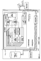
- FIG. 1 is a schematic configuration diagram illustrating a schematic configuration of a verification apparatus 10 that is an information processing apparatus according to the present embodiment.
- FIG. 2 is a schematic configuration diagram illustrating a schematic configuration of the information processing system according to the present embodiment.
- FIG. 3 is an explanatory diagram of the operation of the information processing system at the start of verification.
- FIG. 4 is an explanatory diagram of a specific example of the configuration information database 12.
- FIG. 5 is an explanatory diagram of a specific example of the verification result table 11 a held by the monitoring terminal 11.
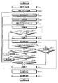
- FIG. 6 is a flowchart for explaining the processing operation when resources are increased from the minimum configuration.
- FIG. 7 is a flowchart for explaining the processing operation when resources are reduced from the maximum configuration.
- FIG. 1 is a schematic configuration diagram illustrating a schematic configuration of a verification apparatus 10 that is an information processing apparatus according to the present embodiment.
- FIG. 2 is a schematic configuration diagram illustrating a schematic configuration of the information processing system according to the present embodiment.
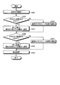
- FIG. 8 is a flowchart for explaining the processing operation of the resource increase amount variable control from the minimum configuration.
- FIG. 9 is a flowchart for explaining the processing operation of the resource reduction amount variable control from the maximum configuration.
- FIG. 10 is an explanatory diagram of the execution result of the information acquisition command issued by the information acquisition unit 43.
- FIG. 11 is an explanatory diagram regarding the analysis of the verification result.
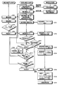
- FIG. 12 is an operation explanatory diagram for explaining the processing of each device during the verification operation of the verification center 1.
- FIG. 1 is a schematic configuration diagram illustrating a schematic configuration of a verification apparatus 10 which is an information processing apparatus according to the present embodiment.
- FIG. 2 is a schematic configuration diagram illustrating a schematic configuration of the information processing system according to the present embodiment.
- the verification apparatus 10 includes a plurality of processing units 20-1 to 2-n (n is an integer of 2 or more), a system storage unit 21, a console interface 22, and a system control unit. 23.
- the system control unit 23 includes an information acquisition unit 43 that obtains the usage amount of hardware resources, a resource control unit 42 that performs dynamic addition / deletion of hardware resources, so-called dynamic reconfiguration, and instruction processing. Part 41 is provided.
- the instruction processing unit 41 receives an instruction from the monitoring terminal connected via the network via the network, and instructs the resource control unit 42 to add / delete resources, and the amount of hardware resources used from the information acquisition unit 43. Get information.
- the information acquisition unit 43 to obtain information on the usage amount of hardware resources, for example, there are the following methods. For example, there is a method in which the information acquisition unit 43 acquires the usage amount of hardware resources by communicating with the operating system. Also, for example, there is a method in which the information acquisition unit 43 accesses the arithmetic processing usage rate measurement unit and the like included in each processing unit directly from the system control unit 23 and confirms the usage status of hardware resources.
- the processing unit 20-1 includes an arithmetic processing unit 31 as a CPU (Central Processing Unit), an arithmetic processing usage rate measuring unit 32 that acquires an operation state of the arithmetic processing unit 31, a memory 33 that is a storage device, and a memory usage rate.
- the memory usage rate measuring unit 34 and the input / output processing unit 35 to be acquired are included.
- the input / output processing unit 35 is connected to an external device such as a hard disk or a console interface 22 that provides an interface for operating the operating system.
- the processing unit 20-1 itself and the arithmetic processing unit 31 and the memory 33 in the processing unit are added / deleted by dynamic reconfiguration to the operating system according to an instruction from the resource control unit 42 of the system control unit 23. I can do it.
- processing units 20-2 to 20-n have the same configuration as the processing unit 20-1, and the plurality of processing units 20-1 to 20-n cooperate with each other to form one operating system (OS) is operating.
- This operating system is stored as program data in the system storage unit 21 realized by a hard disk drive or the like.
- the operation to the operating system is executed through the console interface 22 having a network port, a serial port, and the like.
- a verification center 1 having a plurality of verification devices is connected to a customer terminal 3 via a gateway (GW) 2.
- GW gateway
- the customer terminal 3 and the gateway 2 are connected by a dedicated line or an encrypted network that can be used in a secure (safe) state.
- the verification center 1 is a vendor-side facility that provides information processing apparatuses to customers.
- the verification center 1 includes a plurality of verification apparatuses 10-1 to 10-3, a monitoring terminal 11, a configuration information database 12, and a business A data storage 13 is provided.
- the monitoring terminal 11 has a function of monitoring and managing the verification devices 10-1 to 10-3 and counting the verification results.
- the configuration information database 12 stores the configuration information of the verification apparatuses 10-1 to 10-3 and the availability of addition of resources such as CPU and memory for each configuration.
- the business data storage 13 stores customer business data, and is connected to each of the verification devices 10-1 to 10-3 and the monitoring terminal 3.
- the console interface of the verification apparatuses 10-1 to 10-3 installed in the verification center 1 and the monitoring terminal 11 are connected on the same LAN.
- the verification devices 10-1 to 10-3 and the monitoring terminal 11 are connected to the storage for business data using a storage interface such as Fiber Channel or iSCSI (internet Small Computer System Interface). It is possible to refer to the same data from the verification apparatus.
- a storage interface such as Fiber Channel or iSCSI (internet Small Computer System Interface). It is possible to refer to the same data from the verification apparatus.
- the system control unit of the verification apparatuses 10-1 to 10-3, the monitoring terminal 11, and the configuration information database 12 are connected on the same LAN.
- the verification center 1 since the verification center 1 handles customer's business data, it is considered that the entrance / exit management is strictly performed and the verification center 1 is installed in a state of being completely isolated from the devices installed in the verification centers in other areas. .
- the verification devices 10-1 to 10-3 and the monitoring terminal 11 are connected to a remote customer side terminal via a dedicated line or an encrypted secure network.
- the vendor provides the customer with means for accessing the verification center 1, for example, an IP address, a login ID and password, and the customer remotely accesses the verification device in accordance with the means provided by the vendor.
- the customer can try the device in a secure environment, and it is possible to perform correct performance and operation verification using actual business data that cannot be used for security by verification at a normal verification center. .
- the verification devices 10-1 to 10-3 are switched and the configuration of the verification devices 10-1 to 10-3 is changed, so that when processing business data with various configurations, Performance and operation verification can be performed.
- business data can be received from a customer via a secure network, there is no need to bring a verification information processing apparatus to the customer even when verification is performed using the business data of the customer.
- business data used in the field can be verified at a facility installed on the vendor side, and verification can be performed at low cost.
- FIG. 3 is an explanatory diagram of the operation of the information processing system at the start of verification.
- the customer first obtains access means obtained from the vendor, such as an IP address, login ID and password.
- the customer accesses the verification center 1 from the customer side terminal 3 in accordance with the obtained access means, and transmits business data such as a customer information database to the business data storage 13 through the monitoring terminal 11 (1).
- the customer transmits a verification program used for verification, for example, a batch processing program of customer information, to the monitoring terminal 13 in a form that can be installed in the verification device.
- the verification may be performed by only a part of the verification apparatuses 10-1 to 10-3, or the configuration is sequentially expanded from the minimum configuration of the lowest model (or the highest model). Verification may be performed by sequentially reducing the configuration from the maximum configuration. Which operation pattern is used for verification may be determined by receiving designation from a customer, for example.
- the monitoring terminal 11 inquires the configuration information database 12 about the configuration information of the verification device used for verification and hardware resource addition information such as CPU and memory for each configuration, and obtains the information from the configuration information database 12. (2). Based on the acquired information, the monitoring terminal 11 executes a process for changing the configuration to the minimum configuration of the device (3).
- the monitoring terminal 11 After the configuration change, the monitoring terminal 11 installs the verification program in the verification device and executes verification (4).
- the customer logs in to the verification apparatus from the customer side terminal 3 and inputs a command to execute the verification program to perform manual verification, or automatically from the monitoring terminal 11 for verification Either the program can be executed and the verification can be selected.
- the first operation pattern is an operation pattern for performing verification on all the configurations of the target verification apparatus.
- the second operation pattern is an operation pattern in which the performance value assumed on the customer side, for example, the desired processing time of the batch processing program is provided to the monitoring terminal 11 and the verification is terminated when the performance value is confirmed.
- the monitoring terminal 11 stores the verification result in the verification result table held on the monitoring terminal 11 side after obtaining the verification result. Then, the monitoring terminal 11 determines whether or not resources for the verification apparatus can be added based on the resource availability information obtained from the configuration information database 12.
- the monitoring terminal 11 determines whether or not the performance value assumed on the customer side is satisfied after obtaining the verification result. When the performance value assumed on the customer side is not satisfied, the monitoring terminal 11 determines whether or not resources can be added. On the other hand, when the performance value assumed on the customer side is satisfied, the monitoring terminal 11 ends the verification at that time.
- the verification device transmits the verification result to the monitoring terminal 11 when the verification by the verification device is completed.
- the monitoring terminal 11 determines whether or not resources can be added.
- the monitoring terminal 11 confirms whether or not a resource can be added based on the configuration information obtained from the configuration information database 12. As a result, when the resource can be added, the monitoring terminal 11 issues a resource addition command to the system control unit 23 of the verification apparatus.
- the command processing unit 41 of the system control unit 23 Upon receiving the command, the command processing unit 41 of the system control unit 23 issues an instruction to add the resource designated by the monitoring terminal 11 to the resource control unit 42, and causes the operating system to dynamically add the resource. Then, as soon as the addition of the resource is completed, the monitoring terminal 11 causes the verification program to be executed again.
- the monitoring terminal 11 checks the configuration information table 12, changes the configuration to the configuration described next to the currently verified configuration, and performs verification again. Execute.
- the monitoring terminal 11 when verification is performed with a batch processing program using the customer information database 12, the monitoring terminal 11 automatically verifies all configurations in an operation pattern in which verification is performed on all configurations of the target verification apparatus. To implement. In the operation pattern in which the verification is terminated when the specified performance is achieved, the monitoring terminal 11 provides the monitoring terminal with the desired processing time assumed by the customer in advance, so that the monitoring terminal 11 performs the actual processing time. Verification is automatically performed repeatedly until the configuration becomes shorter than the desired processing time. Then, the monitoring terminal 11 ends the verification when it becomes shorter than the desired processing time.
- FIG. 4 is an explanatory diagram of a specific example of the configuration information database 12.
- the configuration information database 12 includes a main body configuration table 12a, a CPU expansion unit table 12b, a memory expansion unit table 12c, and an HDD expansion unit table 12d.
- the main body configuration table 12a is provided for each verification device, and the configuration type name, basic CPU number, maximum CPU number, basic memory, maximum memory, basic HDD, maximum HDD, CPU expansion availability, memory expansion that the device can take. It has items of availability, availability of HDD expansion, and price.
- configuration of configuration number 1 of the verification apparatus 10-1 is given the model name “AAAAAA1”, the basic CPU “1”, the maximum CPU “4”, the basic memory “8 GB”, the maximum memory “128 GB”, the basic The HDD “146 GB”, the maximum HDD “292 GB”, the CPU expansion “possible”, the memory expansion “possible”, the HDD expansion “possible”, and the price “1000 thousand yen”.
- configuration of configuration number 2 of the verification apparatus 10-1 is given a model name “AAAAAA2”, a basic CPU “2”, a maximum CPU “4”, a basic memory “32 GB”, a maximum memory “128 GB”,
- the basic HDD is “146 GB”, the maximum HDD is “292 GB”, the CPU expansion is “permitted”, the memory expansion is “permitted”, the HDD expansion is “permitted”, and the price is “1500 thousand yen”.
- the configuration of configuration number 3 of the verification apparatus 10-1 is given the model name “AAAAAA3”, the basic CPU “2”, the maximum CPU “4”, the basic memory “64 GB”, the maximum memory “128 GB”, and the basic
- the HDD is “146 GB”, the maximum HDD is “292 GB”, the CPU expansion is “permitted”, the memory expansion is “permitted”, the HDD expansion is “permitted”, and the price is “1980 thousand yen”.
- the main body configuration table 12a is an example arranged in order from the minimum configuration, but the sort order and items of the main body configuration table can be appropriately changed.
- the CPU expansion unit table 12b, the memory expansion unit table 12c, and the HDD expansion unit table 12d are tables indicating change units when resources are added to or deleted from the main body.
- the CPU expansion unit table 12b holds information related to CPU expansion. Specifically, the CPU expansion unit table 12b has items of target device, CPU model name, expansion unit, and price. In the example of FIG. 4, the expansion unit of the CPU “XAAAA1” that can be added to the device “M1000” is “1”, and the price per expansion unit is “500 thousand yen”. Similarly, the expansion unit of the CPU “XAAAA2” that can be added to the device “M1000” is “1”, and the price per expansion unit is “700 thousand yen”.
- the memory expansion unit table 12c holds information related to memory expansion. Specifically, the memory expansion unit table 12c includes items of the target device, the memory model name, the expansion unit, and the price.
- the expansion unit of the memory “XBAAA1” that can be added to the device “M1000” is “8 GB”, and the price per expansion unit is “200 thousand yen”.
- the expansion unit of the memory “XBAAA2” that can be expanded to the device “M1000” is “16 GB”, and the price per expansion unit is “500 thousand yen”.
- the expansion unit of the memory “XBAAA3” that can be expanded to the device “M1000” is “32 GB”, and the price per expansion unit is “1000 thousand yen”.
- the HDD expansion unit table 12d holds information related to HDD expansion. Specifically, the HDD expansion unit table 12d includes items of the target device, HDD model name, expansion unit, and price.
- the extension unit of the HDD “XCAAA1” that can be added to the device “M1000” is “73 GB”, and the price per extension unit is “100,000 yen”.
- the extension unit of the HDD “XCAAA2” that can be added to the device “M1000” is “146 GB”, and the price per extension unit is “120,000 yen”.
- the verification result table 11a includes items of configuration number, number of CPUs, memory capacity, HDD capacity, and configuration price as information indicating the verification configuration, and the verification result is completed until the execution of the verification program. It has the items of processing time required and price performance obtained by dividing the configuration price by the processing time.
- FIG. 6 is a flowchart for explaining the processing operation when resources are increased from the minimum configuration.
- business data is transmitted from the customer terminal 3 (S101) (corresponding to FIG. 3 (1)), and a verification program is also transmitted (S102).
- the monitoring terminal 11 obtains the configuration information from the main body configuration table 12a (S103) (corresponding to FIG. 3 (2)) and constructs a verification environment (S104) (corresponding to FIG. 3 (3)). .
- verification is performed with the minimum configuration with the least hardware resources among the configurations to be verified. That is, when the verification device is designated, the hardware resources are reduced most among the configurations that can be taken by the designated verification device. When all the verification devices are targeted, the verification device (usually the lowest model) that can reduce the hardware resources has the least hardware resources.
- the main body configuration table 12a is arranged in order from the minimum configuration, the first configuration of the main body configuration table 12a may be adopted.
- the monitoring terminal 11 installs a verification program in the constructed environment (S105) (corresponding to (4) in FIG. 3) and performs verification (S106).
- the verification is completed (S108) without issuing a resource shortage message during verification (S107)
- the monitoring terminal 11 acquires the verification result from the verification device (S109).
- the monitoring terminal 11 assumes the verification result. It is determined whether the performance is satisfied (S111). Next, if the monitoring terminal 11 satisfies the assumed performance (S111, Yes), the verification ends (S117).
- the monitoring terminal 11 can refer to the configuration information and add resources to the current configuration? Is determined (S112). If a resource shortage message occurs during verification (S107, Yes), the monitoring terminal 11 refers to the configuration information and determines whether resources can be added to the current configuration (S112).
- the resource control unit 42 uses the resource. Is added (S113), and the monitoring terminal 11 performs verification again (S106).
- the monitoring terminal 11 refers to the main body configuration table 12a. Next, the monitoring terminal 11 determines whether there is the following configuration (S114). If there is the next configuration (S114, Yes), the configuration is switched (S115), and the process proceeds to environment construction again (S104).
- the monitoring terminal 11 determines whether or not switching to a higher model is possible (S116).
- a higher-level model that is, when the operation pattern is to be verified by all the devices and there is a higher-level model than the current device (S116, Yes)
- the device is set to the higher-level model. Switch to the model and obtain the configuration information (S103).
- switching to a higher-level model is impossible, that is, when the current device is the highest-level model even if it is an operation pattern for verification with a specific device or an operation pattern for verification with all devices In (S116, No)
- the monitoring terminal 11 analyzes the verification result to calculate the optimum configuration (S118), outputs the verification result (S119), and ends the process.
- FIG. 7 is a flowchart for explaining the processing operation when resources are reduced from the maximum configuration.
- business data is first transmitted from the customer terminal 3 (S201) (corresponding to FIG. 3 (1)). Then, a verification program is also transmitted from the customer terminal 3 (S202).
- the monitoring terminal 11 obtains configuration information from the main body configuration table 12a (S203) (corresponding to FIG. 3 (2)), and constructs a verification environment (S204) (corresponding to FIG. 3 (3)). .
- verification is performed with the maximum configuration having the largest resource among the configurations to be verified. That is, when the verification device is designated, the configuration having the most resources among the configurations that can be taken by the designated verification device. When all the verification devices are targeted, the configuration of the verification device (usually the highest model) that can increase the resource is the most resource-rich.
- the main body configuration database 12a is arranged in order from the minimum configuration, the last configuration of the main body configuration database 12a may be adopted. Further, when the components are arranged in order from the maximum configuration, the first configuration of the main body configuration database 12a may be adopted.
- the monitoring terminal 11 installs a verification program in the constructed environment (S205) (corresponding to (4) in FIG. 3), and performs verification (S206). An error of insufficient hardware resources occurs during this verification. If the verification is completed (S207, Yes), the verification is terminated as it is (S217), while the verification is completed (S208, No) without giving a resource shortage error during verification (S208).
- the service terminal 11 acquires the verification result from the verification device (S209).
- the monitoring terminal 11 Determines whether the verification result is lower than the assumed performance (S211). Next, if the monitoring terminal 11 is lower than the assumed performance (S211, Yes), the verification ends (S217).
- the monitoring terminal 11 When the estimated performance is exceeded (S211, No) or when the assumed performance is not specified (S210, No), the monitoring terminal 11 refers to the configuration information and reduces resources from the current configuration. It is determined whether or not it is possible (S212).
- the monitoring terminal 11 refers to the main body configuration table 12a. Then, the monitoring terminal 11 determines whether there is a next configuration of the same model based on the main body configuration table 12a (S214). As a result of the determination, if there is a next configuration of the same model (S214, Yes), the configuration is switched to the next configuration of the same model (S215), and the process proceeds to environment construction again (S204).
- the monitoring terminal 11 determines whether switching to a lower model is possible (S216). If it is possible to switch to the lower model (S216, Yes), the configuration information is obtained by switching the device to the lower model (S203).
- the case where switching to a lower model is possible is an operation pattern in which verification is performed in all devices, and there is a model lower than the current device.
- the verification is terminated (S217).
- the current device is the lowest model even if the operation pattern is to verify with a specific device or the operation pattern to verify with all devices. Is the case.
- the monitoring terminal 11 analyzes the verification result to calculate the optimum configuration (S218), outputs the verification result (S219), and ends the process.
- the monitoring terminal 11 determines whether a resource can be added / deleted, it does not verify all possible configurations of the verification device, but instead of an expansion unit based on the load status of the verification device at the time of verification. May be skipped. For example, the CPU usage rate, the memory usage rate, etc. are monitored as the load status, and the amount of resources to be added / reduced is determined by comparison with a preset reference value.
- FIG. 8 is a flowchart for explaining the processing operation when verification is performed while increasing hardware resources from the minimum configuration.
- the processing operation shown in FIG. 8 is processing performed as internal processing of the resource addition step (S113) shown in FIG.
- the load status is output from the verification device to the monitoring terminal 11 (S301), and it is determined whether or not the average CPU usage rate is equal to or greater than a predetermined threshold value X% (S302).
- X% a predetermined threshold value
- the average CPU usage rate is equal to or greater than X%
- the total number of CPU cores of the verification device is changed to the current Y times (Y> 1) configuration (S303), and the average CPU usage rate is X If it is less than%, normal CPU resource addition is performed (S304).
- normal CPU resource addition is a process of adding a predetermined number of CPUs.
- the monitoring terminal 11 determines whether or not the average memory usage rate is equal to or higher than a predetermined threshold A% (S305). As a result, if the average memory usage rate is A% or more, the memory capacity is changed to the current B times (B> 1) or more (S306), and if the average memory usage rate is less than A%, the normal memory is used. Resource addition is performed (S307). Here, normal memory resource addition is processing for adding a predetermined memory capacity. Then, the above configuration change is applied to the verification apparatus (S308), and the process is terminated.
- work which verifies can be changed.
- a value determined in advance by the customer may be used.
- an example has been described in which it is determined whether or not to add a resource using the CPU usage rate and the memory usage rate. A value can be used.
- the increase amount of the resource is changed for both the CPU and the memory has been described here, the increase amount is changed for any one of the resource increases, and the other always increases the resource by a constant amount. You may do it.
- FIG. 9 is a flowchart for explaining the processing operation when verification is performed while reducing hardware resources from the maximum configuration.
- the processing operation shown in FIG. 9 is processing performed as internal processing of the resource reduction step (S213) shown in FIG.
- the resource reduction variable control first, the load status is output from the verification device to the other monitoring terminal 11 (S401), and it is determined whether or not the average CPU usage rate is equal to or less than the threshold value X% (S402). As a result, if the average CPU usage rate is X% or less, the total number of cores is changed to the current Y times (0 ⁇ Y ⁇ 1) or less (S403). If the average CPU usage rate is higher than X%, it is normal.
- CPU resource reduction is implemented (S404).
- normal CPU resource reduction is a process of reducing the number of CPUs by a predetermined number.
- the monitoring terminal 11 determines whether or not the average memory usage rate is equal to or less than the threshold value A% (S405). As a result, if the average memory usage is A% or less, the memory capacity is changed to the current B times (0 ⁇ B ⁇ 1) or less (S406), and if the average memory usage is greater than A%. Normal memory resource reduction is performed (S407). Here, normal memory resource reduction is processing for reducing a predetermined memory capacity. Then, the above configuration change is applied to the verification apparatus (S408), and the process is terminated.
- the information acquisition unit 43 of the system control unit 23 directly calculates the calculation processing usage rate measurement unit from the calculation processing usage rate measurement unit 32 and the memory usage rate measurement unit 34 in the processing unit. 32 and the memory usage rate measurement unit 34 are accessed and acquired. Further, as described below, the load status of the verification apparatus can be acquired by issuing an information acquisition command to the operating system.
- the information acquisition command is a command capable of grasping the usage status of the system hardware resources such as the vmstat command and the top command.
- the vmstat command and the top command can acquire the usage rate and memory usage of the arithmetic processing unit incorporated in the operating system.
- the system control unit 23 holds the total number of arithmetic processing units and the total memory capacity in the current configuration as information.
- FIG. 10 is an explanatory diagram of an execution result of the information acquisition command issued by the information acquisition unit 43.
- the numbers shown in the id column of the cpu term represent the idle rate of each CPU, that is, the unused time rate.
- the average of four CPUs indicates that there is an idle time of 71.5%, and the CPU usage rate is 28.5%.
- the free column in the “memory” section indicates the free memory capacity. Since these total values are handled as the total free memory capacity, the average memory usage rate can be calculated from the information on the total memory capacity of the system control unit 23.
- the CPU usage rate reference value is 80%
- the number of cores is doubled
- the memory usage rate reference value is 80%
- the memory is increased.
- the unit is set to double, and the CPU usage rate and the memory usage rate are monitored on the monitoring terminal side.
- the average CPU usage rate is 80% or more, for example, the total number of CPU cores of the verification device is changed to a configuration that is twice the current configuration, and the memory usage rate is 80% or more. Then, the memory capacity can be changed to twice the current configuration.
- the monitoring terminal 11 also monitors an error message related to a lack of hardware resources from the verification device.
- the configuration is immediately displayed when a message indicating a shortage of resources such as memory or CPU is displayed from the operating system of the verification device. Cancel the verification in, and add resources. This is because the lack of resources such as memory and CPU is displayed, and the lack of resources becomes empty without waiting for the end of verification.
- the monitoring terminal 11 stops displaying verification at that point in time when the verification device confirms the display of a message indicating insufficient memory. Determine whether memory resources can be added. If it can be added, the monitoring terminal 11 issues a configuration change command for adding the memory of the verification device, and executes the verification again as soon as the configuration change is completed.
- the monitoring terminal 11 changes the verification device to a higher model than the verification device. Then, the monitoring terminal 11 performs a process of inquiry and acquisition of configuration information to the configuration information database 12, installation of a verification program, configuration change, and verification.
- the monitoring terminal 11 performs an analysis based on the stored verification result table. Specifically, as shown in FIG. 11, the order of performance of the verification device or the order of price performance obtained by dividing the performance of the verification device by the price may be rearranged, and the upper configuration may be output or rearranged. Instead, the verification results of the previous configuration may be output in the verification execution order.
- the batch processing program is rearranged in the order of short processing time, and the configuration with the best performance or multiple configurations with the highest performance are output.
- the configuration with the best price performance or a plurality of configurations with the highest price performance are output.
- the numerical value decreases as the performance increases, such as processing time the price performance value decreases as the performance is divided by the price.
- the evaluation may be performed by rearranging in ascending order.
- the price performance is calculated by looking at the difference from the predetermined reference value (performance improvement) so that the higher the price performance value, the better the value. It may be calculated.
- the analysis result can also be output by e-mail or the like to the customer side terminal, for example.
- FIG. 12 is an operation explanatory diagram for explaining the processing of each device during the verification operation of the verification center 1.
- the monitoring terminal 11 requests configuration information provision of the verification device used for verification (S601). Specifically, a configuration information confirmation command is sent to the configuration information database 12.
- the configuration information database 12 confirms the configuration information of the specified verification device (S801), and provides the monitoring device 11 with the configuration information of the specified device body and the additional information applicable to the specified device. (S802).
- the monitoring terminal 11 obtains the configuration information from the configuration information database 12 (S602), issues a configuration change command to the verification device based on the configuration information (S603), and calculates the price of the configuration (S604). Then, the configuration and price are added to the verification result table (S701).
- the verification apparatus that has received the configuration change command changes the configuration based on the command (S501), and performs verification (S502).
- the verification device When an error message indicating a resource shortage is output in the verification (S503, Yes), the verification device outputs to the monitoring terminal 11. Further, without issuing an error message indicating a resource shortage (S503, No), the verification result is sent to the monitoring terminal 12 when the verification is completed (S504).
- the verification result is stored in the verification result table (S702), and the price performance obtained by dividing the performance value from the verification result such as performance and the price by the price is obtained.
- the price performance information is calculated (S703) and stored in the verification result table (S704).
- the monitoring terminal 11 determines whether the resource can be changed. (S608).
- the resource is changed based on the resource change unit (S609), and the process returns to step S602.
- the monitoring terminal 11 determines whether the main body configuration table has the next configuration (S610), and when the next configuration exists (S610, Yes). Shifts to the next configuration and returns to step S602.
- the verification is completed and a completion notification is output (S612).
- the verification result table is aggregated (S705), sorted based on performance and price performance, the highest sorted configuration is calculated as the recommended configuration (S706), and the analysis result is output ( S707), the process is terminated.
- the information processing apparatus when a verification facility is prepared at the verification center and verified by a customer via the network. Then, the configuration is automatically changed by the verification device, and the optimum hardware configuration for the customer is calculated.
- Customer can send business data via a secure network to a verification device installed in an isolated environment of the verification center, and the customer can perform verification automatically or by the customer. Also, by verifying all the configurations that can be configured by the verification apparatus at that time while dynamically changing it, it is possible to calculate a hardware configuration optimal for the customer's business.
- the customer can grasp the optimal hardware configuration for his / her business, and since the verification is performed in a secure environment, performance verification can be performed using actual business data. Furthermore, since verification can be performed with various configurations of the assumed apparatus, it is possible to select a configuration that is most suitable for one's business, and as a result, it is not necessary to purchase unnecessary hardware assets. In addition, even when satisfactory performance is not achieved with the assumed apparatus, verification can be performed using the higher-level model, so that the range of hardware selection can be expanded.
Landscapes
- Engineering & Computer Science (AREA)
- General Engineering & Computer Science (AREA)
- Theoretical Computer Science (AREA)
- Computer Hardware Design (AREA)
- Quality & Reliability (AREA)
- Physics & Mathematics (AREA)
- General Physics & Mathematics (AREA)
- Debugging And Monitoring (AREA)
Abstract
検証用装置に複数の処理ユニットを持たせ、各処理ユニットには演算処理部、演算処理使用率計測部、メモリ、メモリ使用率計測部、入出力処理部を持たせる。システム制御部は、複数の処理ユニット上でオペレーティングシステムを動作させ、所定の処理を実行させて演算処理装置とメモリの負荷状態を情報取得にて取得する。資源制御部42が負荷状態に基づいて処理ユニットのハードウェア構成を動的に制御することで、適切な装置構成を検証する。
Description
本発明は、情報処理装置の構成を検証し得る情報処理装置の構成検証用の情報処理装置、情報処理システムおよび情報処理装置構成検証方法に関する。
従来、所定の処理を実行するための情報処理装置を新たに構築・購入する場合、実行したい処理を検証用の実機で動作させて処理性能の検証を行なっていた。例えば、顧客に対して情報処理装置を納入する場合、顧客の業務データを使用した検証を行なっていた。
かかる検証により、選択した構成が実際の業務を遂行するのに処理性能の過不足が無いかを確認することができる。
なお、仮想コンピュータシステムで構成変更する技術や、LAN(Local area network)環境の構成を最適化する技術、指定した構成の性能を評価する技術が知られているが、顧客へ現実に提供する情報処理装置のように、特定の処理に使用する情報処理装置の最適な構成を検証することは困難であった。
従来の技術は、検証用の実機における性能を確認するものである。従って、検証後、実際に顧客が情報処理装置を購入する際には、検証結果から推測した構成の装置を購入することになる。しかし、検証用とは異なる装置であるため、実際の業務に使用する際には、CPU(Central Processing Unit)やメモリなどのコンピュータリソースの過不足が発生する場合があった。
そのため、購入した機器でコンピュータリソース不足に陥り結局機器の追加購入/交換を行うようなケースや、コンピュータリソースが過剰な構成を購入した事により余分なコストを払うことになってしまうようなケースが発生するという問題点があった。
また、ベンダ側も顧客側の要望に応えるために、検証用に複数の構成を用意したり、または検証の度にオプションなどを用いて構成変更を行なうなどのコストがかかるという問題点があった。
本発明は、上述した従来技術にかかる問題点を解消し、課題を解決するためになされたものであり、所定の処理に対して適切な情報処理装置の構成を低コストで検証可能な検証用の情報処理装置、情報処理システムおよび情報処理装置構成検証方法を提供することを目的とする。
上述した課題を解決し、目的を達成するために、開示の装置、システムおよび方法は、オペレーティングシステム上でプログラムが動作する情報処理装置において、演算処理部毎に演算処理使用率を取得し、情報処理装置全体における性能情報を算出し、プログラムの動作による性能情報に基づいて、複数の演算処理部のうち所定の個数の演算処理部をオペレーティングシステムからアクセス可能に認識させる。
開示の装置、システム及び方法によれば、情報処理装置の構成を低コストで検証可能な検証用の情報処理装置、情報処理システムおよび情報処理装置構成検証方法を得ることができるという効果を奏する。
1 検証センタ
2 ゲートウェイ
3 顧客用端末
10,10-1~10-3 検証用装置
11 監視用端末
12 構成情報データベース
13 業務データ格納用ストレージ
20-1~20-n 処理ユニット
21 システム格納部
22 コンソール用インタフェース
23 システム制御部
31 演算処理部
32 演算処理使用率計測部
33 メモリ
34 メモリ使用率計測部
35 入出力処理部
41 命令処理部
42 資源制御部
43 情報取得部
2 ゲートウェイ
3 顧客用端末
10,10-1~10-3 検証用装置
11 監視用端末
12 構成情報データベース
13 業務データ格納用ストレージ
20-1~20-n 処理ユニット
21 システム格納部
22 コンソール用インタフェース
23 システム制御部
31 演算処理部
32 演算処理使用率計測部
33 メモリ
34 メモリ使用率計測部
35 入出力処理部
41 命令処理部
42 資源制御部
43 情報取得部
以下に、本実施例にかかる情報処理装置、情報処理システムおよび情報処理装置構成検証方法について、図面を参照して詳細に説明する。
図1は、本実施例にかかる情報処理装置である検証用装置10の概要構成を示す概要構成図である。また、図2は、本実施例にかかる情報処理システムの概要構成を示す概要構成図である。
図1に示したように、検証用装置10は、その内部に複数の処理ユニット20-1~2-n(nは2以上の整数)、システム格納部21、コンソール用インタフェース22、システム制御部23を有する。
システム制御部23は、ハードウェアリソースの使用量を入手する情報取得部43、ハードウェアリソースの動的な追加/削除、所謂動的再構成(Dynamic Reconfiguration)を行なう資源制御部42、および命令処理部41を有する。
命令処理部41は、ネットワークで接続された監視用端末からの命令をネットワーク経由で受け付け、資源制御部42へのリソース追加/削除指示や、情報取得部43からのハードウェアリソースの使用量についての情報を入手する。
また、情報取得部43が、ハードウェアリソースの使用量についての情報を入手する方法としては、例えば次のような方法がある。例えば、情報取得部43が、オペレーティングシステムと通信を行なってハードウェアリソースの使用量を入手する方法がある。又、例えば、情報取得部43が、システム制御部23から直接、各処理ユニットが有する演算処理使用率計測部などにアクセスし、ハードウェアリソースの使用状況を確認する方法がある。
処理ユニット20-1は、CPU(Central Processing Unit)としての演算処理部31、演算処理部31の動作状態を取得する演算処理使用率計測部32、記憶装置であるメモリ33、メモリの使用率を取得するメモリ使用率計測部34、入出力処理部35を有する。入出力処理部35には、ハードディスクなどの外部装置や、オペレーティングシステムを操作するためのインタフェースを提供するコンソール用インタフェース22を接続する。
処理ユニット20-1自体および処理ユニット内の演算処理部31とメモリ33については、システム制御部23の資源制御部42からの指示により、オペレーティングシステムに対して動的再構成により追加/削除を行なうことが出来る。
また、処理ユニット20-2~20-nは処理ユニット20-1と同様の構成を有し、複数の処理ユニット20-1~20-nは、互いに協働して全体で一つのオペレーティングシステム(OS)を動作させている。このオペレーティングシステムは、ハードディスクドライブなどで実現されるシステム格納部21にプログラムデータとして格納される。オペレーティングシステムへの操作については、ネットワークポートやシリアルポートなどを有するコンソール用インタフェース22を通して実行される。
本実施例にかかる情報処理システムでは、図2に示したように、複数の検証用装置を備えた検証センタ1をゲートウェイ(GW)2を介して顧客用端末3に接続している。ここで、顧客用端末3とゲートウェイ2との間は専用回線や暗号化されセキュア(安全)な状態で使用できるネットワークにより接続することが考えられる。
検証センタ1は、情報処理装置を顧客に提供するベンダ側の設備であり、検証センタ1の内部に複数の検証用装置10-1~10-3、監視用端末11、構成情報データベース12、業務データ格納用ストレージ13を有する。
監視用端末11は、検証用装置10-1~10-3を監視・管理し、検証結果を集計する機能などを有する。構成情報データベース12は、検証用装置10-1~10-3の構成情報および構成毎のCPUやメモリなどリソースの追加可否などを格納する。業務データ格納用ストレージ13は、顧客の業務データを格納し、各検証用装置10-1~10-3および監視用端末3に接続されている。
検証センタ1内に設置されている検証用装置10-1~10-3のコンソール用インタフェースと監視用端末11とは同一のLAN上に接続されている。そして、検証用装置10-1~10-3と監視用端末11とは業務データ格納用ストレージにFibre ChannelやiSCSI(internet Small Computer System Interface)などのストレージ用インタフェースを用いて接続されており、すべての検証用装置から同一のデータを参照することが可能な状態となっている。
また、監視用のネットワークとして、検証用装置10-1~10-3のシステム制御部と、監視用端末11および構成情報データベース12は同一のLAN上に接続されている。
加えて、検証センタ1は、顧客の業務データを扱うため、入退室管理を厳重にし、他のエリアの検証センタに設置されている装置からは完全に隔離された状態で設置することが考えられる。
既に述べたように、検証用装置10-1~10-3および監視用端末11は、専用回線または暗号化されたセキュアなネットワークを介して、遠隔の顧客側端末と接続される。ベンダは顧客に対し、検証センタ1へアクセスする手段、例えばIPアドレスやログイン用のIDとパスワード等を提供し、顧客はベンダから提供された手段に則って遠隔から検証用装置へアクセスする。
従って、顧客はセキュアな環境で装置の試用を行うことができ、通常の検証センタでの検証ではセキュリティ上使用できない実際の業務データなどを用いて、正しい性能や動作検証を行うことが可能となる。
そして、検証センタ側では、検証用装置10-1~10-3の切り替えや、検証用装置10-1~10-3の構成の変更を行なって、多様な構成で業務用データの処理時における性能や動作検証を行なうことができる。加えて、セキュアなネットワークを介して顧客から業務データを受信できるため、顧客の業務データを用いて検証を行なう場合でも顧客側に検証用の情報処理装置を持ち込む必要は無い。さらに、ベンダ側に設置した施設で実地で使用する業務データの検証が可能であり、低コストで検証を行なうことができる。
図3は、検証開始時の情報処理システムの動作の説明図である。検証を開始する際には、まず、顧客は、ベンダから入手したアクセス手段、例えばIPアドレスやログイン用のIDとパスワード等を入手する。顧客は入手したアクセス手段に則り、顧客側端末3から検証センタ1内にアクセスし、監視用端末11経由で業務データ、例えば顧客情報データベースなどを業務データ格納用ストレージ13へ送信する(1)。併せて、顧客は、検証に使用する検証用プログラム、例えば顧客情報のバッチ処理プログラムなどを検証用装置にインストール可能な形で監視用端末13に送信する。
ここで、検証は検証用装置10-1~10-3のうち一部の装置のみで実施してもよいし、最下位機種の最小構成から順次構成を拡大して(もしくは、最上位機種の最大構成から順次構成を縮小して)検証を実施してもよい。いずれの動作パターンで検証を行なうかは、例えば顧客からの指定を受け付けて決定すればよい。
つぎに、監視用端末11は検証に用いる検証用装置の構成情報および構成毎のCPUやメモリなどのハードウェアリソースの追加可否情報を構成情報データベース12に問い合わせ、構成情報データベース12から上記情報を入手する(2)。監視用端末11は入手した情報を元に、当該装置の最小構成に構成変更を行う処理を実行する(3)。
構成変更後、監視用端末11は検証用プログラムを検証用装置へインストールを行ない、検証を実行する(4)。
検証の開始については、顧客が顧客側端末3から検証用装置にログインし、コマンドを入力することにより検証用プログラムを実行して手動で検証を行うか、もしくは監視用端末11から自動で検証用プログラムを実行して検証を行うかのどちらかが選択可能となる。
自動で検証を行う場合には、2つの動作パターンのいずれかを選択することができる。第1の動作パターンは、対象となる検証用装置の全ての構成に対して検証を行なう動作パターンである。第2の動作パターンは、顧客側で想定する性能値、例えばバッチ処理プログラムの希望処理時間を監視用端末11に提供し、その性能値が確認出来た時点で検証を終了する動作パターンである。
対象検証用装置の全構成に対して検証を行なう動作パターンでは、監視用端末11は、検証結果の入手後に、監視用端末11側で持っている検証結果テーブルに検証結果を格納する。そして、監視用端末11は、構成情報データベース12より入手したリソースの追加可否情報を元に、検証用装置のリソース追加可否を判断する。
また、指定された性能を達成した時点で検証を終了する動作パターンでは、監視用端末11は、検証結果の入手後、顧客側で想定する性能値を満たしているかどうかの判断を行なう。顧客側で想定する性能値を満たしていない場合、監視用端末11は、リソース追加可否の判断を行なう。一方、顧客側で想定する性能値を満たしている場合、監視用端末11は、その時点で検証を終了させる。
いずれの動作パターンについても、検証用装置での検証完了時、検証用装置は監視用端末11に検証結果を送信する。
また、リソースの追加可否判断は、監視用端末11が行なう。監視用端末11は、構成情報データベース12より入手した構成情報を元に、リソースの追加可否を確認する。その結果、リソースの追加が可能な場合には、監視用端末11は検証用装置のシステム制御部23に向けてリソースの追加命令を発行する。
命令を受けたシステム制御部23の命令処理部41は、監視用端末11の指定したリソースを追加する指示を資源制御部42へ発行し、オペレーティングシステムに対して動的にリソースを追加させる。そして、リソースの追加が完了し次第、監視用端末11は再度検証用プログラムを実行させる。
一方、リソースの追加が不可である場合には、監視用端末11は構成情報テーブル12を確認し、現在検証している構成の次に記載されている構成へ構成を変更させて、再度検証を実行する。
例えば、顧客情報データベース12を用いたバッチ処理プログラムでの検証を行う場合、対象検証用装置の全構成に対して検証を行なう動作パターンでは、監視用端末11は、すべての構成について自動的に検証を実施する。また、指定された性能を達成した時点で検証を終了する動作パターンでは、顧客が想定する希望処理時間を予め監視用端末に提供しておくことにより、監視用端末11は、実際の処理時間が希望処理時間よりも短くなる構成になるまで自動的に繰り返し検証を実行する。そして監視用端末11は、希望処理時間よりも短くなった時点で検証を終了させる。
図4は、構成情報データベース12の具体例の説明図である。図4に示した例では、構成情報データベース12は、本体構成テーブル12a、CPU増設単位テーブル12b、メモリ増設単位テーブル12c、HDD増設単位テーブル12dを有する。
本体構成テーブル12aは、検証用装置ごとに設けられ、当該装置が取りうる構成の型名、基本CPU数、最大CPU数、基本メモリ、最大メモリ、基本HDD、最大HDD、CPU増設可否、メモリ増設可否、HDD増設可否、価格の項目を有する。
例えば、検証用装置10-1の構成番号1の構成は、型名「AAAAAA1」が与えられ、基本CPU「1」、最大CPU「4」、基本メモリ「8GB」、最大メモリ「128GB」、基本HDD「146GB」、最大HDD「292GB」、CPU増設「可」、メモリ増設「可」、HDD増設「可」、価格「1000千円」である。同様に、検証用装置10-1の構成番号2の構成は、型名「AAAAAA2」が与えられ、基本CPU「2」、最大CPU「4」、基本メモリ「32GB」、最大メモリ「128GB」、基本HDD「146GB」、最大HDD「292GB」、CPU増設「可」、メモリ増設「可」、HDD増設「可」、価格「1500千円」である。また、検証用装置10-1の構成番号3の構成は、型名「AAAAAA3」が与えられ、基本CPU「2」、最大CPU「4」、基本メモリ「64GB」、最大メモリ「128GB」、基本HDD「146GB」、最大HDD「292GB」、CPU増設「可」、メモリ増設「可」、HDD増設「可」、価格「1980千円」である。
同様の本体構成テーブルは、検証用装置10-2,3にも存在する。なお、この本体構成テーブル12aは、最小構成から順に並べた例であるが、本体構成テーブルのソート順、項目などについては適宜変更可能である。
CPU増設単位テーブル12b、メモリ増設単位テーブル12c、HDD増設単位テーブル12dは、本体に対してリソースの追加・削除を行なう際の変更単位を示すテーブルである。
CPU増設単位テーブル12bは、CPUの増設に関する情報を保持する。具体的にはCPU増設単位テーブル12bでは、対象装置、CPUの型名、増設単位、価格の項目を有する。図4の例では、装置「M1000」に増設可能なCPU「XAAAA1」の増設単位は「1」、増設単位あたりの価格が「500千円」である。同様に装置「M1000」に増設可能なCPU「XAAAA2」の増設単位は「1」、増設単位あたりの価格が「700千円」である。
メモリ増設単位テーブル12cは、メモリの増設に関する情報を保持する。具体的にはメモリ増設単位テーブル12cでは、対象装置、メモリの型名、増設単位、価格の項目を有する。図4の例では、装置「M1000」に増設可能なメモリ「XBAAA1」の増設単位は「8GB」、増設単位あたりの価格が「200千円」である。同様に装置「M1000」に増設可能なメモリ「XBAAA2」の増設単位は「16GB」、増設単位あたりの価格が「500千円」である。さらに、同様に装置「M1000」に増設可能なメモリ「XBAAA3」の増設単位は「32GB」、増設単位あたりの価格が「1000千円」である。
HDD増設単位テーブル12dは、HDDの増設に関する情報を保持する。具体的には、HDD増設単位テーブル12dでは、対象装置、HDDの型名、増設単位、価格の項目を有する。図4の例では、装置「M1000」に増設可能なHDD「XCAAA1」の増設単位は「73GB」、増設単位あたりの価格が「100千円」である。同様に、装置「M1000」に増設可能なHDD「XCAAA2」の増設単位は「146GB」、増設単位あたりの価格が「120千円」である。
つぎに、図5を参照し、監視用端末11が保持する検証結果テーブル11aの具体例について説明する。図5に示した例では、検証結果テーブル11aは、検証構成を示す情報として構成番号、CPU数、メモリ容量、HDD容量、構成価格の項目を有し、検証結果として検証プログラムの実行完了までに要した処理時間と、構成価格を処理時間で除したプライスパフォーマンスの項目を有する。
具体的には、検証結果テーブル11aでは、構成番号「0」であるCPU数「1」、メモリ容量「8GB」、HDD容量「146GB」、構成価格「1000千円」の構成において処理時間「240秒」、プライスパフォーマンス「4.17」である。同様に、構成番号「1」であるCPU数「1」、メモリ容量「12GB」、HDD容量「146GB」、構成価格「1800千円」の構成において処理時間「230秒」、プライスパフォーマンス「7.83」である。また、構成番号「2」であるCPU数「1」、メモリ容量「24GB」、HDD容量「292GB」、構成価格「2200千円」の構成において処理時間「210秒」、プライスパフォーマンス「10.48」である。
つぎに、検証処理の具体的な処理動作について説明する。図6は、最小構成からリソースを増加させる場合の処理動作を説明するフローチャートである。検証を行なう場合、まず、顧客用端末3から業務データを送信し(S101)(図3(1)に対応)、併せて検証プログラムを送信する(S102)。
ここで、監視用端末11は、構成情報を本体構成テーブル12aから入手し(S103)(図3(2)に対応)、検証環境の構築を行なう(S104)(図3(3)に対応)。この環境構築では、検証対象の構成のうち、最もハードウェアリソースの少ない最小構成で検証を行なう。すなわち、検証用装置が指定されている場合には、指定された検証用装置が取りうる構成のうち、最もハードウェアリソースを減らした構成である。又、全ての検証用装置を対象とする場合には、最もハードウェアリソースを少なくし得る検証用装置(通常は最下位機種)の最もハードウェアリソースが少ない構成である。ここで、本体構成テーブル12aを最小構成から順に並べていれば、本体構成テーブル12aの最初の構成を採用すればよい。
その後、監視用端末11は、構築した環境に検証プログラムをインストールし(S105)(図3の(4)に対応)、検証実施する(S106)。検証中にリソース不足のメッセージを出すことなく(S107,No)、検証が完了した(S108)場合には、監視用端末11は、検証用装置から検証結果を取得する(S109)。
ここで、指定された性能を達成した時点で検証を終了する動作パターンで検証を行なっている場合、すなわち想定性能の指定がある場合(S110,Yes)、監視用端末11は、検証結果が想定性能を満たしているかを判定する(S111)。次に、監視用端末11は、想定性能を満足していれば(S111,Yes)、検証を終了する(S117)。
そして、想定性能を満足していない場合(S111,No)、想定性能の指定が無い場合(S110,No)、監視用端末11は、構成情報を参照し、現在の構成にリソースを追加できるかを判定する(S112)。また、検証中にリソース不足のメッセージが発生した場合(S107,Yes)、監視用端末11は、構成情報を参照し、現在の構成にリソースを追加できるかを判定する(S112)。
その結果、リソースが追加可能である場合、すなわち、使用している検証用装置がリソース追加可能な装置であり、かつリソースが最大になっていない場合(S112,Yes)、資源制御部42はリソースを追加し(S113)、監視用端末11は、再度検証を実施する(S106)。
一方、リソースの追加が不可能である場合、すなわち、使用している検証用装置がリソース追加不可能な装置であるか、追加可能であっても既にリソースが最大の構成になっている場合(S112,No)、監視用端末11は、本体構成テーブル12aを参照する。次に、監視用端末11は、次の構成があるかいなかを判定する(S114)。そして、次の構成がある場合には(S114,Yes)、構成を切り替えて(S115)、再度環境構築に移行する(S104)。
一方、本体構成テーブル12aに次の構成が無い場合(S114,No)、監視用端末11は、上位機種への切り替えが可能か否かを判定する(S116)。そして、上位機種への切り替えが可能である場合、すなわち、全ての装置で検証を行なう動作パターンであって、かつ現在の装置よりも上位の機種が存在する場合(S116,Yes)、装置を上位機種へ切り替えて構成情報を入手する(S103)。一方、上位機種への切り替えが不可能である場合、すなわち、特定の装置で検証を行なう動作パターンか、全ての装置で検証を行なう動作パターンであっても現在の装置が最上位機種である場合(S116,No)には検証を終了する(S117)。
検証の終了後、監視用端末11は、検証結果を分析して最適な構成を算出し(S118)、検証結果を出力して(S119)、処理を終了する。
図7は、最大構成からリソースを減少させる場合の処理動作を説明するフローチャートである。最大構成からリソースを減少させて検証を行なう場合、まず、顧客用端末3から業務データを送信する(S201)(図3(1)に対応)。そして顧客用端末3から、併せて検証プログラムを送信する(S202)。
つぎに、監視用端末11は、本体構成テーブル12aから構成情報を入手し(S203)(図3(2)に対応)、検証環境の構築を行なう(S204)(図3(3)に対応)。この環境構築では、検証対象の構成のうち、もっともリソースの大きい最大構成で検証を行なう。すなわち、検証用装置が指定されている場合には、指定された検証用装置が取りうる構成のうち、最も多くのリソースを搭載した構成である。そして、全ての検証用装置を対象とする場合には、最もリソースを多くし得る検証用装置(通常は最上位機種)の最もリソースが多い構成である。ここで、本体構成データベース12aを最小構成から順に並べていれば、本体構成データベース12aの最後の構成を採用すればよい。また、最大構成から順に並べている場合には、本体構成データベース12aの最初の構成を採用すればよい。
その後、監視用端末11は、構築した環境に検証プログラムをインストールし(S205)(図3の(4に対応)、検証を実施する(S206)。この検証中にハードウェアリソース不足のエラーが発生した場合には(S207,Yes)、そのまま検証を終了する(S217)。一方、検証中にリソース不足のエラーを出すことなく(S207,No)、検証が完了した(S208)場合には、監視用端末11は、検証用装置から検証結果を取得する(S209)。
ここで、指定された性能を達成する最小構成が得られた時点で検証を終了する動作パターンで検証を行なっている場合、すなわち想定性能の指定がある場合(S210,Yes)、監視用端末11は、検証結果が想定性能を下回っているかを判定する(S211)。次に、監視用端末11は、想定性能を下回っていれば(S211,Yes)、検証を終了する(S217)。
そして、想定性能を上回っている場合(S211,No)、または想定性能の指定が無い場合(S210,No)には、監視用端末11は、構成情報を参照し、現在の構成からリソースを削減できるか否かを判定する(S212)。
その結果、リソースが削減可能である場合、すなわち、使用している検証用装置がリソース削減可能な装置であり、かつリソースが最小になっていない場合(S212,Yes)、リソースを削減し(S213)、再度検証を実施する(S206)。
一方、リソースの削減が不可能である場合、すなわち、使用している検証用装置がリソース削減不可能な装置であるか、削減可能であっても既にリソースが最小の構成になっている場合(S212,No)、監視用端末11は、本体構成テーブル12aを参照する。そして、監視用端末11は、本体構成テーブル12aに基づいて、同一機種の次の構成があるか否かを判定する(S214)。判定の結果、同一機種の次の構成がある場合(S214,Yes)、同一機種の次の構成に切り替えて(S215)、再度環境構築に移行する(S204)。
一方、本体構成テーブルに同一機種の次の構成が無い場合(S214,No)、監視用端末11は、下位機種への切り替えが可能か否かを判定する(S216)。そして、下位機種への切り替えが可能である場合(S216,Yes)、装置を下位機種へ切り替えて構成情報を入手する(S203)。ここで、下位機種への切り替えが可能である場合とは、全ての装置で検証を行なう動作パターンであって、かつ現在の装置よりも下位の機種が存在する場合である。一方、下位機種への切り替えが不可能である場合(S216,No)には検証を終了する(S217)。ここで、下位機種への切り替えが不可能である場合とは、特定の装置で検証を行なう動作パターンか、全ての装置で検証を行なう動作パターンであっても現在の装置が最下位機種である場合である。
検証の終了後、監視用端末11は、検証結果を分析して最適な構成を算出し(S218)、検証結果を出力して(S219)、処理を終了する。
なお、監視用端末11がリソースの追加・削除の可否を判断する際、当該検証用装置の取り得る全ての構成を検証するのではなく、検証時における検証用装置の負荷状況に基づいて増設単位をスキップするようにしてもよい。例えばCPU使用率やメモリ使用率などを負荷状況として監視し、予め設定した基準値と比較して増設・削減するリソース量を決定する。
このように負荷状態に応じてハードウェアリソースを増減しながら検証を行なう事により、全ての構成の組み合わせに対して検証を行うよりも、大幅に検証時間を短縮することが可能となる。
図8は、最小構成からハードウェアのリソースを増加しながら検証を行なう場合の処理動作を説明するフローチャートである。図8に示した処理動作は、図6に示したリソース追加ステップ(S113)の内部処理として行なわれる処理である。この制御では、まず、検証用装置から監視用端末11へ負荷状況を出力し(S301)、平均CPU使用率が所定の閾値X%以上であるか否かを判定する(S302)。その結果、平均CPU使用率がX%以上であれば、検証用装置が有するCPUの総コア数が現在のY倍(Y>1)の構成に変更し(S303)、平均CPU使用率がX%未満であれば通常のCPUリソース追加を実施する(S304)。ここで、通常のCPUリソース追加とは、予め定めた数のCPUを追加する処理である。
さらに監視用端末11は、平均メモリ使用率が所定の閾値A%以上であるか否かを判定する(S305)。その結果、平均メモリ使用率がA%以上であればメモリ容量が現在のB倍(B>1)以上の構成に変更し(S306)、平均メモリ使用率がA%未満であれば通常のメモリリソース追加を実施する(S307)。ここで、通常のメモリリソース追加とは、予め定めたメモリ容量を追加する処理である。そして、以上の構成変更を検証用装置に適用して(S308)、処理を終了する。
なお、X、Y、A、Bの値については、検証を行う業務によって使用する値を変更することができる。具体的には、予め顧客が定めた値を用いればよい。また、ここではCPU使用率とメモリ使用率を用いてリソースを追加するか否かを判断する場合を例に説明をおこなったが、リソースを追加するか否かを判断には、他の任意の値を用いることができる。さらに、ここでは、CPUとメモリの双方についてリソースの増加量を変更する場合について説明したが、何れか一方のリソースの増加について増加量を変更することとし、他方は常に一定量でリソースを増加させるようにしてもよい。
図9は、最大構成からハードウェアリソースを削減しながら検証を行なう場合の処理動作を説明するフローチャートである。図9に示した処理動作は、図7に示したリソース削減ステップ(S213)の内部処理として行なわれる処理である。リソース削減量可変制御では、まず、検証用装置から監視用他端末11へ負荷状況を出力し(S401)、平均CPU使用率が閾値X%以下であるか否かを判定する(S402)。その結果、平均CPU使用率がX%以下であれば総コア数が現在のY倍(0<Y<1)以下の構成に変更し(S403)、平均CPU使用率がX%より大きければ通常のCPUリソース削減を実施する(S404)。ここで、通常のCPUリソース削減とは、CPUの数を予め定めた数だけ削減する処理である。
さらに監視用端末11は、平均メモリ使用率が閾値A%以下であるか否かを判定する(S405)。その結果、平均メモリ使用率がA%以下であればメモリ容量が現在のB倍(0<B<1)以下の構成に変更し(S406)、平均メモリ使用率がA%より大きい場合には通常のメモリリソース削減を実施する(S407)。ここで、通常のメモリリソース削減とは、予め定めたメモリ容量を削減する処理である。そして、以上の構成変更を検証用装置に適用して(S408)、処理を終了する。
なお、検証用装置の負荷状況については、システム制御部23の情報取得部43が、処理ユニット内にある演算処理使用率計測部32およびメモリ使用率計測部34より、直接演算処理使用率計測部32およびメモリ使用率計測部34に対してアクセスして取得する。また、以下に挙げるとおり、オペレーティングシステムに対して情報取得コマンドを発行することにより、検証用装置の負荷状況を取得することもできる。
情報取得コマンドとは、例えばvmstatコマンドやtopコマンドなどシステムのハードウェアリソースの使用状況を把握することが出来るコマンドである。vmstatコマンドやtopコマンドは、オペレーティングシステムに組み込まれている演算処理部の使用率およびメモリの使用量を取得することが出来る。また、システム制御部23は、現在の構成における全演算処理部数や全メモリ容量を情報として保持している。
図10は、情報取得部43が発行した情報取得コマンドの実行結果の説明図である。図10において、cpuの項のidの列に示される数字が各CPUのidle率、すなわち未使用の時間率を表す。図10の例では、
(82+62+64+78)/4=71.5
となり、4つのCPUを平均すると、71.5%のidle時間があることを示し、CPU使用率は28.5%となる。
(82+62+64+78)/4=71.5
となり、4つのCPUを平均すると、71.5%のidle時間があることを示し、CPU使用率は28.5%となる。
同様にmemoryの項のfreeの列が空きメモリ容量を示す。これらの合計値が全空きメモリ容量として扱われるため、システム制御部23が持っている全メモリ容量の情報からメモリの平均使用率を算出することが出来る。
例えば、顧客情報データベースを用いたバッチ処理プログラムでの検証を行う場合に、CPU使用率の基準値を80%、コア数の増加を2倍、メモリ使用率の基準値を80%、メモリの増加単位を2倍と設定し、監視用端末側でCPU使用率とメモリ使用率を監視する。監視の結果、平均CPU使用率が例えば80%以上であったなら検証用装置のCPUの総コア数を現在の構成の2倍になる構成へ変更させ、メモリ使用率が80%以上であったなら、現在の構成の2倍のメモリ容量へ変更させることができる。
また、監視用端末11は、検証用装置からのハードウェアリソース不足に関するエラーメッセージについても監視を行う。監視用端末11は、最小構成からハードウェアリソースを増加させつつ検証を行なっている場合に、検証用装置のオペレーティングシステムからメモリやCPUなどのリソース不足を示すメッセージが表示されると即座に当該構成での検証を中止し、リソースの追加の処理を行う。これは、メモリやCPUなどのリソース不足を示すメッセージが表示されたことで、検証の終了を待たずともリソースの不足が空からとなるためである。
例えば、顧客情報データベースを用いたバッチ処理プログラムでの検証を行う場合に、監視用端末11は、検証用装置にてメモリ不足を示すメッセージの表示を確認した場合、その時点で検証を中止させ、メモリのリソース追加の可否を判断する。そして、追加可能である場合には監視用端末11は検証用装置のメモリを追加する構成変更命令を発行し、構成変更が完了し次第、再度検証を実行する。
さらに、最下位機種の最小構成から順次ハードウェアリソースを増加させながら検証を行うパターンでの検証では、監視用端末11は、当該検証用装置よりも上位機種に検証用装置を変更する。そして、監視用端末11は、構成情報データベース12への構成情報の問い合わせおよび入手、検証用プログラムのインストール、構成変更、検証のプロセスを実施する。
つぎに、検証結果の出力について説明する。全ての検証が終了後、監視用端末11は、保存してある検証結果テーブルを元に、分析を実施する。具体的には、図11に示すように、検証用装置の性能順や検証用装置の性能を価格で除算したプライスパフォーマンス順に並び替え、上位の構成を出力しても良いし、並び替えを行なわずに検証の実施順に前構成の検証結果を出力してもよい。
性能のよい順番では、例えばバッチ処理プログラムの処理時間が短い順番に並べ替えを行なって、最も性能のよい構成や、性能が上位の複数の構成を出力する。また、プライスパフォーマンスのよい順番では、最もプライスパフォーマンスのよい構成や、プライスパフォーマンスが上位の複数の構成を出力する。なお、処理時間など性能が上がると数値が下がってしまうようなケースでは、性能を価格で除算するとプライスパフォーマンスの値は小さいほど良い値となる。この場合、昇順で並べ替えて評価を行なえばよい。また、高性能であるほど値が下がる数値については、所定の基準値からの差分(性能向上分)を見てプライスパフォーマンスを算出することで、プライスパフォーマンスの値が高いほうが良い値となるように算出してもよい。分析結果は、例えば顧客側端末へメールなどで出力することもできる。
図12は、検証センタ1の検証動作時における各装置の処理について説明する動作説明図である。検証を行なう場合、まず監視用端末11が検証に使用する検証用装置の構成情報提供依頼を行なう(S601)。具体的には、構成情報確認命令が構成情報データベース12に送られる。
構成情報データベース12は、指定された検証用装置の構成情報を確認し(S801)、指定された装置本体の構成情報と、指定された装置に適用可能な増設情報を監視用端末11に提供する(S802)。
監視用端末11は構成情報データベース12から構成情報を入手し(S602)、構成情報に基づき検証用装置に対して構成変更命令を発行し(S603)、当該構成の価格を算出して(S604)、検証結果テーブルへ構成と価格を追加する(S701)。
一方で、構成変更命令を受けた検証用装置は、命令に基づいて構成を変更し(S501)、検証を実施する(S502)。検証においてリソース不足を示すエラーメッセージが出た場合(S503,Yes)、検証用装置は監視用端末11に出力する。また、リソース不足を示すエラーメッセージを出すことなく(S503,No)、検証が完了した(S504)には検証結果を監視用端末12に送付する。
監視用端末11は、検証用端末から検証結果を入手すると(S605)、検証結果テーブルに検証結果を格納し(S702)、性能などの検証結果と価格から性能値を価格で除算したプライスパフォーマンスを算出し(S703)、検証結果テーブルにプライスパフォーマンス情報を格納する(S704)。
また、性能値であって、当該性能値を達成した場合には検証を終了する想定性能値がある場合(S606,Yes)には、想定性能値を満たしたかを判定し(S607)、指定された想定性能値を満たしている場合には(S607,Yes)、検証を完了する(S612)。
性能の指定が無い場合(S606,No)、もしくは性能指定があっても指定された性能値を満たしていない場合(S607,No)には、監視用端末11は、リソースの変更が可能か判定する(S608)。
リソースの変更が可能である場合(S608,Yes)、リソースの変更単位に基づきリソース変更を行なって(S609)、ステップS602に戻る。リソースの変更が不可能である場合(S608,No)、監視用端末11は、本体構成テーブルに次の構成があるかを判定し(S610)、次の構成がある場合(S610,Yes)には次の構成に移行してステップS602に戻る。
本体構成テーブルに次の構成が無い場合(S610,No)、上位機種や下位機種など他の機種への切り替えが可能であるか否かを判定し(S611)、他機種への切り替えが可能であれば(S611,Yes)、機種を切り替えてステップS601に戻る。
他機種への切り替えが可能でない場合(S611,No)には、検証を完了し、完了通知を出力する(S612)。この完了通知を受けて検証結果テーブルを集計し(S705)、性能やプライスパフォーマンスを元にソートして、ソート結果が上位の構成を推奨構成として算出し(S706)、分析結果を出力して(S707)、処理を終了する。
以上説明してきたように、本実施例にかかる報処理装置、情報処理システムおよび情報処理装置構成検証方法では、検証センタにて検証用の設備を用意し、ネットワーク経由で顧客に検証してもらう際に、検証用装置で自動的に構成を変更し、顧客に最適なハード構成を算出する。
顧客は、検証センタの隔離された環境に設置された検証用装置へセキュアなネットワーク経由で業務データを送付し、自動もしくは顧客が自ら検証を実施することが可能できる。また、その際に検証用装置が構成可能な全ての構成を動的に変更しながら検証することにより、顧客の業務に最適なハード構成を算出することが可能となる。
そのため、顧客は自分の業務に最適なハード構成を把握することが出来、また、セキュアな環境での検証であるため、実業務データを用いて性能検証などを行うことが出来る。さらに、想定している装置の様々な構成で検証を行うことが出来るため、自分の業務に最適な構成を選択することが出来、結果的に不必要なハード資産を購入する必要がなくなる。加えて、想定している装置で満足出来る性能が出なかった場合にも、その上位機種を用いて検証を行うことが可能となるため、ハードウェア選択の幅を広げることが可能となる。
また、ハードウェアベンダは、あらゆる構成の検証機を用意する必要がなくなるため、設備投資を抑制出来る。すなわち、最大構成のみを用意しておけば、検証用装置で様々な構成へ変更することが出来るため、複数の構成を用意する必要や、検証の度に実機の構成を変更したりする手間を省くことが出来る。また、検証結果情報の蓄積を行うことで、業務種別における最適なハード構成を把握することが出来、構成案の検討や商談での提案などにも使用することが可能となる。
Claims (19)
- オペレーティングシステム上でプログラムが動作する情報処理装置において、
前記プログラムが動作するとともに、単位時間当たりの負荷を表す演算処理使用率を計測する演算処理使用率計測部をそれぞれ有する複数の演算処理部と、
前記演算処理使用率計測部から前記演算処理部毎に演算処理使用率を取得することにより、前記情報処理装置全体における性能情報を算出する情報取得部と、
前記プログラムの動作による前記性能情報に基づいて、前記複数の演算処理部のうち所定の個数の演算処理部を、前記オペレーティングシステムからアクセス可能に認識させる資源制御部を有することを特徴とする情報処理装置。 - 前記資源制御部はさらに、
前記演算処理部の個数の取り得る組み合わせを表す複数の装置構成のうちいずれか一つの装置構成として、前記複数の演算処理部のうち所定の個数の演算処理部を、前記オペレーティングシステムからアクセス可能に認識させることを特徴とする請求項1記載の情報処理装置。 - 前記演算処理装置はさらに、
前記プログラムが格納される記憶装置を有し、
前記情報取得部はさらに、
前記演算処理使用率計測部から前記演算処理部毎に取得する演算処理使用率に加え、前記記憶容量使用率計測部から取得した、前記プログラムの動作に使用される記憶容量を表す記憶容量使用率に基づいて、前記情報処理装置全体における性能情報を算出し、
前記資源制御部はさらに、
前記演算処理部の個数と前記記憶装置の記憶容量の取り得る組み合わせを表す複数の装置構成のうちいずれか一の装置構成として、前記複数の演算処理部のうち所定の個数の演算処理部と前記記憶部のうち所定の記憶容量の記憶部を、前記オペレーティングシステムからアクセス可能に認識させることを特徴とする請求項1記載の情報処理装置。 - 前記情報処理装置はさらに、
ネットワークを介して端末装置に接続され、
前記端末装置から前記プログラムの起動を行うことを特徴とする請求項1~3のいずれか1項に記載の情報処理装置。 - 前記端末装置からの前記プログラムの起動は、
前記ネットワーク上で暗号化されたコマンドにより行われることを特徴とする請求項4記載の情報処理装置。 - 第1の情報処理装置と、第2の情報処理装置と、監視装置が接続された情報処理システムにおいて、
前記第1の情報処理装置は、
第1のオペレーティングシステム上でプログラムが動作するとともに、単位時間当たりの負荷を表す演算処理使用率を計測する演算処理使用率計測部をそれぞれ有する複数の演算処理部と、
前記演算処理使用率計測部から前記演算処理部毎に演算処理使用率を取得することにより、前記第1の情報処理装置における性能情報を算出する情報取得部を有し、
前記第2の情報処置装置は、
第2のオペレーティングシステムが動作するとともに、単位時間当たりの負荷を表す演算処理使用率を計測する演算処理使用率計測部をそれぞれ有する複数の演算処理部を有し、
前記監視装置は、前記第1の情報処理装置における前記演算処理使用率に基づいて、前記第1の情報処理装置から前記第2の情報処理装置に切り換えることにより、前記プログラムを動作させることを特徴とする情報処理システム。 - 前記第1の演算処理装置はさらに、
前記プログラムが格納される記憶装置を有し
前記第2の演算処理装置はさらに、
前記プログラムが格納される記憶装置を有し、
前記情報取得部はさらに、
前記演算処理使用率計測部から前記演算処理部毎に取得する演算処理使用率に加え、前記記憶容量使用率計測部から取得した、前記プログラムの動作に使用される記憶容量を表す記憶容量使用率に基づいて、前記情報処理装置全体における性能情報を算出することを特徴とする請求項6記載の情報処理システム。 - 前記監視装置はさらに、
ネットワークを介して端末装置に接続され、
前記端末装置から前記プログラムの起動を行うことを特徴とする請求項6又は7記載の情報処理システム。 - 前記端末装置からの前記プログラムの起動は、
前記ネットワーク上で暗号化されたコマンドにより行われることを特徴とする請求項8記載の情報処理システム。 - 複数の演算処理部を有する情報処理装置に対し、プログラム実行時にアクセス可能な演算処理部の数を指定することで検証用の環境を構築するステップと、
前記情報処理装置に前記プログラムを実行させるステップと、
前記プログラム実行中における前記演算処理部の演算処理使用率と、前記プログラムの実行完了までに要した処理時間とを少なくとも取得するステップと、
予め指定された複数の検証環境の全てについて検証が終了したか否かを判定し、検証の終了していない検証環境が残っている場合には前記プログラム実行時にアクセス可能な演算処理部の数を変更して前記検証環境を切り替えるステップと、
を含んだことを特徴とする情報処理装置構成検証方法。 - 前記検証用の環境を構築するステップは、さらに、
前記情報処理装置が前記プログラム実行時に使用可能な記憶容量を前記検証用の環境として指定し、
前記検証環境を切り替えるステップは、検証の終了していない検証環境が残っている場合には前記証プログラム実行時に使用可能な記憶容量を変更して前記検証環境を切り替えることを特徴とする請求項10に記載の情報処理装置構成検証方法。 - 前記演算処理使用率と前記処理時間とを取得した結果、指定された性能が達成された場合に検証を終了し、達成されていない場合に前記検証環境を切り替えるステップに移行することを特徴とする請求項10に記載の情報処理装置構成検証方法。
- 前記検証環境を切り替えるステップは、前記情報処理装置が取りうる範囲内の構成で検証を行なった後に、他の情報処理装置に前記プログラムを実行させることを特徴とする請求項10に記載の情報処理装置構成検証方法。
- 前記検証用の環境を構築するステップは、前記情報処理装置の全ての演算処理部をアクセス可能とし、前記検証環境を切り替えるステップは演算処理部を削減することを特徴とする請求項10に記載の情報処理装置構成検証方法。
- 前記検証用の環境を構築するステップは、前記情報処理装置の演算処理部のうちいずれか一つをアクセス可能とし、前記検証環境を切り替えるステップは演算処理部を増加させることを特徴とする請求項10に記載の情報処理装置構成検証方法。
- 前記検証環境を切り替えるステップは、前記演算処理使用率と前記処理時間とを取得した結果に基づいて検証環境の変更内容を決定することを特徴とする請求項10に記載の情報処理装置構成検証方法。
- 前記プログラムが使用するデータを暗号化して前記情報処理装置に提供することを特徴とする請求項10に記載の情報処理装置構成検証方法。
- 前記演算処理使用率と前記処理時間とを分析して出力するステップを含んだことを特徴とする請求項10に記載の情報処理装置構成検証方法。
- 複数の演算処理部を有する情報処理装置に対し、プログラム実行時にアクセスする演算処理部の数を選択することで検証用の環境を構築するステップと、
前記情報処理装置に前記プログラムを実行させるステップと、
前記プログラム実行中における前記演算処理部の演算処理使用率と、前記プログラムの実行完了までに要した処理時間とのうちを少なくとも何れか一方を検証結果として取得するステップと、
前記検証結果を使用して、前記演算処理部の数を決定するステップと
を含んだことを特徴とする情報処理装置構成検証方法。
Priority Applications (1)
| Application Number | Priority Date | Filing Date | Title |
|---|---|---|---|
| PCT/JP2009/056384 WO2010109669A1 (ja) | 2009-03-27 | 2009-03-27 | 情報処理装置、情報処理システムおよび情報処理装置構成検証方法 |
Applications Claiming Priority (1)
| Application Number | Priority Date | Filing Date | Title |
|---|---|---|---|
| PCT/JP2009/056384 WO2010109669A1 (ja) | 2009-03-27 | 2009-03-27 | 情報処理装置、情報処理システムおよび情報処理装置構成検証方法 |
Publications (1)
| Publication Number | Publication Date |
|---|---|
| WO2010109669A1 true WO2010109669A1 (ja) | 2010-09-30 |
Family
ID=42780378
Family Applications (1)
| Application Number | Title | Priority Date | Filing Date |
|---|---|---|---|
| PCT/JP2009/056384 Ceased WO2010109669A1 (ja) | 2009-03-27 | 2009-03-27 | 情報処理装置、情報処理システムおよび情報処理装置構成検証方法 |
Country Status (1)
| Country | Link |
|---|---|
| WO (1) | WO2010109669A1 (ja) |
Cited By (1)
| Publication number | Priority date | Publication date | Assignee | Title |
|---|---|---|---|---|
| JP2017090969A (ja) * | 2015-11-02 | 2017-05-25 | Necプラットフォームズ株式会社 | コンピュータ装置、制御方法およびプログラム |
Citations (5)
| Publication number | Priority date | Publication date | Assignee | Title |
|---|---|---|---|---|
| JP2000029852A (ja) * | 1998-07-13 | 2000-01-28 | Nec Corp | マルチプロセッサシステム |
| JP2002183416A (ja) * | 2000-12-15 | 2002-06-28 | Hitachi Ltd | システム提案方法及びその実施装置並びにその処理プログラムを記録した記録媒体 |
| JP2003131907A (ja) * | 2001-10-19 | 2003-05-09 | Toshiba Corp | Webシステムの性能評価システム、方法及びプログラム |
| JP2003196125A (ja) * | 2001-12-28 | 2003-07-11 | Ns Solutions Corp | 性能評価情報管理装置、性能評価装置、性能評価情報管理方法、性能評価方法、記録媒体およびプログラム |
| JP2007334387A (ja) * | 2006-06-12 | 2007-12-27 | Fujitsu Ltd | データ処理システムの試験方法、試験プログラム及び試験装置 |
-
2009
- 2009-03-27 WO PCT/JP2009/056384 patent/WO2010109669A1/ja not_active Ceased
Patent Citations (5)
| Publication number | Priority date | Publication date | Assignee | Title |
|---|---|---|---|---|
| JP2000029852A (ja) * | 1998-07-13 | 2000-01-28 | Nec Corp | マルチプロセッサシステム |
| JP2002183416A (ja) * | 2000-12-15 | 2002-06-28 | Hitachi Ltd | システム提案方法及びその実施装置並びにその処理プログラムを記録した記録媒体 |
| JP2003131907A (ja) * | 2001-10-19 | 2003-05-09 | Toshiba Corp | Webシステムの性能評価システム、方法及びプログラム |
| JP2003196125A (ja) * | 2001-12-28 | 2003-07-11 | Ns Solutions Corp | 性能評価情報管理装置、性能評価装置、性能評価情報管理方法、性能評価方法、記録媒体およびプログラム |
| JP2007334387A (ja) * | 2006-06-12 | 2007-12-27 | Fujitsu Ltd | データ処理システムの試験方法、試験プログラム及び試験装置 |
Non-Patent Citations (1)
| Title |
|---|
| MASAHIKO SO, UNIX DE MANABU MULTI-THREAD· PROGRAMMING, INTERFACE, vol. 20, no. 5, 1 May 1995 (1995-05-01), pages 200 * |
Cited By (1)
| Publication number | Priority date | Publication date | Assignee | Title |
|---|---|---|---|---|
| JP2017090969A (ja) * | 2015-11-02 | 2017-05-25 | Necプラットフォームズ株式会社 | コンピュータ装置、制御方法およびプログラム |
Similar Documents
| Publication | Publication Date | Title |
|---|---|---|
| US9686352B2 (en) | Saturation detection and admission control for storage devices | |
| CN101853197B (zh) | 确定服务器负载能力 | |
| US7225242B2 (en) | System and method for matching storage device queue depth to server command queue depth | |
| JP4898805B2 (ja) | システムの構成パラメータ・セットを最適化するための方法、プログラムおよび装置 | |
| US10048989B2 (en) | Automated workload analysis and simulation process | |
| US20080059602A1 (en) | Load balancing method for data I/O paths between groups in which multi-path management is employed | |
| JP2010146420A (ja) | 余剰資源管理システム、その管理方法、及びサーバ装置 | |
| US20020152301A1 (en) | System and method for determining the state of a service within a computer network | |
| JP2008234632A (ja) | クライアント・サーバ又はホスティング環境における計算ジョブの多目的配分 | |
| US20030074431A1 (en) | Automatically switching shared remote devices in a dense server environment thereby allowing the remote devices to function as a local device | |
| JP5531278B2 (ja) | サーバ構成管理システム | |
| JP2011198262A (ja) | 計算機システムにおけるシステム管理方法、及び管理システム | |
| KR20130017234A (ko) | 서비스형 소프트웨어 목록 갱신 방법 및 이를 위한 시스템 | |
| JP2015191324A (ja) | ストレージ管理装置、性能調整方法及び性能調整プログラム | |
| CN115202580A (zh) | 一种多路径设备检测方法、装置、设备、存储介质 | |
| CN118672638B (zh) | 一种基于微服务架构的软件应用管理方法 | |
| KR102150016B1 (ko) | 클라우드 서버의 자동 스케일링 방법, 장치 및 컴퓨터-판독가능기록매체 | |
| CN108985556A (zh) | 流量调度的方法、装置、设备和计算机存储介质 | |
| US20040044772A1 (en) | Method and system for controlling admission to a server using temporary server access | |
| CN117321972A (zh) | 用于智能基础设施协调的基于机器学习的应用规模调整引擎 | |
| WO2010109669A1 (ja) | 情報処理装置、情報処理システムおよび情報処理装置構成検証方法 | |
| CN112751945B (zh) | 一种分布式云服务的实现方法、装置、设备和存储介质 | |
| CN109710447A (zh) | 用于数据访问的方法、装置、介质和计算设备 | |
| JP2010277265A (ja) | 店舗管理システム及びその制御方法 | |
| JP3683216B2 (ja) | 性能評価装置、情報処理方法およびプログラム |
Legal Events
| Date | Code | Title | Description |
|---|---|---|---|
| 121 | Ep: the epo has been informed by wipo that ep was designated in this application |
Ref document number: 09842283 Country of ref document: EP Kind code of ref document: A1 |
|
| NENP | Non-entry into the national phase |
Ref country code: DE |
|
| 122 | Ep: pct application non-entry in european phase |
Ref document number: 09842283 Country of ref document: EP Kind code of ref document: A1 |
|
| NENP | Non-entry into the national phase |
Ref country code: JP |