WO2010107008A1 - Wheel for automobile - Google Patents
Wheel for automobile Download PDFInfo
- Publication number
- WO2010107008A1 WO2010107008A1 PCT/JP2010/054379 JP2010054379W WO2010107008A1 WO 2010107008 A1 WO2010107008 A1 WO 2010107008A1 JP 2010054379 W JP2010054379 W JP 2010054379W WO 2010107008 A1 WO2010107008 A1 WO 2010107008A1
- Authority
- WO
- WIPO (PCT)
- Prior art keywords
- wheel
- spoke
- disk
- flange
- rim
- Prior art date
Links
Images


Classifications
-
- B—PERFORMING OPERATIONS; TRANSPORTING
- B60—VEHICLES IN GENERAL
- B60B—VEHICLE WHEELS; CASTORS; AXLES FOR WHEELS OR CASTORS; INCREASING WHEEL ADHESION
- B60B3/00—Disc wheels, i.e. wheels with load-supporting disc body
- B60B3/04—Disc wheels, i.e. wheels with load-supporting disc body with a single disc body not integral with rim, i.e. disc body and rim being manufactured independently and then permanently attached to each other in a second step, e.g. by welding
- B60B3/041—Disc wheels, i.e. wheels with load-supporting disc body with a single disc body not integral with rim, i.e. disc body and rim being manufactured independently and then permanently attached to each other in a second step, e.g. by welding characterised by the attachment of rim to wheel disc
- B60B3/044—Disc wheels, i.e. wheels with load-supporting disc body with a single disc body not integral with rim, i.e. disc body and rim being manufactured independently and then permanently attached to each other in a second step, e.g. by welding characterised by the attachment of rim to wheel disc characterised by cross-sectional details of the attachment, e.g. the profile
-
- B—PERFORMING OPERATIONS; TRANSPORTING
- B60—VEHICLES IN GENERAL
- B60B—VEHICLE WHEELS; CASTORS; AXLES FOR WHEELS OR CASTORS; INCREASING WHEEL ADHESION
- B60B3/00—Disc wheels, i.e. wheels with load-supporting disc body
- B60B3/002—Disc wheels, i.e. wheels with load-supporting disc body characterised by the shape of the disc
- B60B3/007—Disc wheels, i.e. wheels with load-supporting disc body characterised by the shape of the disc in the intermediate section
-
- B—PERFORMING OPERATIONS; TRANSPORTING
- B60—VEHICLES IN GENERAL
- B60B—VEHICLE WHEELS; CASTORS; AXLES FOR WHEELS OR CASTORS; INCREASING WHEEL ADHESION
- B60B3/00—Disc wheels, i.e. wheels with load-supporting disc body
- B60B3/04—Disc wheels, i.e. wheels with load-supporting disc body with a single disc body not integral with rim, i.e. disc body and rim being manufactured independently and then permanently attached to each other in a second step, e.g. by welding
- B60B3/041—Disc wheels, i.e. wheels with load-supporting disc body with a single disc body not integral with rim, i.e. disc body and rim being manufactured independently and then permanently attached to each other in a second step, e.g. by welding characterised by the attachment of rim to wheel disc
- B60B3/042—Disc wheels, i.e. wheels with load-supporting disc body with a single disc body not integral with rim, i.e. disc body and rim being manufactured independently and then permanently attached to each other in a second step, e.g. by welding characterised by the attachment of rim to wheel disc characterised by circumferential position of attachment means
-
- B—PERFORMING OPERATIONS; TRANSPORTING
- B60—VEHICLES IN GENERAL
- B60B—VEHICLE WHEELS; CASTORS; AXLES FOR WHEELS OR CASTORS; INCREASING WHEEL ADHESION
- B60B3/00—Disc wheels, i.e. wheels with load-supporting disc body
- B60B3/10—Disc wheels, i.e. wheels with load-supporting disc body apertured to simulate spoked wheels
-
- B—PERFORMING OPERATIONS; TRANSPORTING
- B60—VEHICLES IN GENERAL
- B60B—VEHICLE WHEELS; CASTORS; AXLES FOR WHEELS OR CASTORS; INCREASING WHEEL ADHESION
- B60B2360/00—Materials; Physical forms thereof
- B60B2360/10—Metallic materials
- B60B2360/102—Steel
-
- B—PERFORMING OPERATIONS; TRANSPORTING
- B60—VEHICLES IN GENERAL
- B60B—VEHICLE WHEELS; CASTORS; AXLES FOR WHEELS OR CASTORS; INCREASING WHEEL ADHESION
- B60B2360/00—Materials; Physical forms thereof
- B60B2360/14—Physical forms of metallic parts
- B60B2360/141—Sheet-metals
-
- B—PERFORMING OPERATIONS; TRANSPORTING
- B60—VEHICLES IN GENERAL
- B60B—VEHICLE WHEELS; CASTORS; AXLES FOR WHEELS OR CASTORS; INCREASING WHEEL ADHESION
- B60B2900/00—Purpose of invention
- B60B2900/30—Increase in
- B60B2900/311—Rigidity or stiffness
Definitions
- the present invention relates to an automobile wheel.
- Patent Document 1 includes a rim and a disk, and the disk includes a plurality of spokes, a ring-shaped disk flange that connects the outer peripheral ends of the wheels of the plurality of spokes and is joined to the inner peripheral surface of the drop part of the rim.
- An automobile wheel including the above is disclosed.
- a large decorative hole is formed between the spokes so that the outer end in the radial direction of the wheel is located near the disc flange.
- the conventional automobile wheel has the following problems.
- the disk flange Since the disk flange is ring-shaped and the decoration hole is large and close to the disk flange, the rigidity difference between the position where the decoration hole is provided and the position where the spoke is provided is large in the circumferential direction of the wheel. Therefore, the rim may be deformed (distorted) when the disc is inserted into the rim. When the rim is deformed, the wheel runout accuracy (rim runout accuracy) decreases.
- the spoke is composed of a bottom wall portion, a side wall portion, and an edge portion in order to suppress the bending deformation of the spoke and improve durability. Therefore, when the disk flange is drawn by press working, the outer shape of the disk flange connected to the outside in the radial direction of the spoke tends to be uneven. Therefore, the durability of the wheel and the runout accuracy of the wheel are reduced.
- the present invention for achieving the above object is as follows. (1) (a) a rim having a drop portion; (B) a plurality of spokes extending radially outward in the radial direction of the wheel, and a disk flange located at the outer radial end of the wheel and connecting the outer radial ends of the multiple spokes in the circumferential direction of the wheel. , A disc in which a decorative hole is formed between the spokes; An automotive wheel in which the drop portion and the disk flange portion are joined, The disk flange has a non-contact portion that is in non-contact with the inner peripheral surface of the rim, at a portion extending outward in the wheel radial direction of the center line in the width direction of the spoke.
- the non-contact portion is a portion of the disc flange that extends outward in the wheel radial direction of the center line in the width direction of the spoke, and includes a recess that is recessed inward in the wheel radial direction from the inner peripheral surface of the rim.
- the disc flange has a non-contact portion that is in non-contact with the inner peripheral surface of the rim at the radially outward extension portion of the spoke in the width direction of the center line.
- the rigidity of the disk at the position where the spoke is provided in the circumferential direction of the wheel can be reduced. Therefore, the difference in rigidity between the position where the decorative hole is provided and the position where the spoke is provided on the disc in the circumferential direction of the wheel can be reduced as compared with the conventional case.
- the non-contact portion can be provided by providing the notch, and the weight of the wheel can be reduced.
- the non-contact portion can be provided without increasing the manufacturing process by providing the recess.
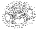
- Example 1 It is a perspective view when the wheel for motor vehicles of this invention Example 1 is seen from the back side. It is a front view of the wheel for vehicles of the example 1 of the present invention, and is a figure in the case where the circumferential direction positions of the spoke and the hub mounting bolt hole are different. It is sectional drawing of the wheel for motor vehicles of this invention Example 1, and is sectional drawing in case the corrugated part is provided in the bottom wall part of the spoke. It is a perspective view in case the non-contact part consists of a substantially rectangular notch of the disk of the wheel for motor vehicles of Example 1 of this invention. It is a perspective view in case the non-contact part consists of a substantially semicircle notch of the disk of the wheel for motor vehicles of Example 1 of this invention.
- FIG. It is a perspective view in case the non-contact part consists of a substantially semi-oval-shaped notch of the disk of the wheel for motor vehicles of this invention Example 1.
- FIG. It is a perspective view in case the non-contact part consists of a wide substantially rectangular notch of the disk of the motor vehicle wheel of Example 1 of this invention.
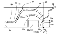
- a tapered transition portion is provided between the decorative hole and the disk flange extending linearly in the wheel axial direction in a cross-sectional view of the automobile wheel according to the first embodiment of the present invention, and the diameter of the transition portion on the decorative hole side is the disk flange. It is a fragmentary sectional view when it is larger than the diameter of the side.
- a tapered transition portion is provided between the decorative hole and the disk flange extending linearly in the wheel axial direction in a cross-sectional view of the automobile wheel according to the first embodiment of the present invention, and the diameter of the transition portion on the decorative hole side is the disk flange. It is a fragmentary sectional view when it is smaller than the diameter of the side.
- FIGS. 1 to 13 show a vehicle wheel according to Embodiment 1 of the present invention.
- FIGS. 14 and 15 show a general vehicle wheel different from the present invention.
- FIG. 16 shows the present invention.
- the wheel for motor vehicles of Example 2 is shown.
- FIGS. 8 to 11 are also applicable to the second embodiment of the present invention. Portions common to the first embodiment and the second embodiment of the present invention are denoted by the same reference numerals throughout the first and second embodiments of the present invention. First, parts common to the first and second embodiments of the present invention will be described.
- An automobile wheel (hereinafter also simply referred to as a wheel) 10 includes a rim 20 and a disk 30 as shown in FIG.
- the wheel 10 is a two-piece wheel in which the rim 20 and the disk 30 are separately manufactured and integrated by welding or using a joining member such as a rivet (not shown).
- the wheel 10 is made of steel, for example. However, the wheel 10 may not be made of steel as long as it is a two-piece wheel of the rim 20 and the disk 30, and may be made of aluminum alloy, titanium alloy, or the like.
- the rim 20 includes an inner flange portion 21, an inner bead seat portion 22, an inner sidewall portion 23, a drop portion 24, an outer sidewall portion 25, an outer bead seat portion 26, and an outer flange portion 27. .
- the inner flange portion 21, the inner bead seat portion 22, and the inner sidewall portion 23 are more in the wheel axial direction when the wheel 10 is mounted on the vehicle than the outer sidewall portion 25, the outer bead seat portion 26 and the outer flange portion 27. Located near the inside of the vehicle.
- the disk 30 is manufactured from a plate material.
- the disk 30 includes a hub hole 31, a hub mounting portion 32, a spoke 33, a decorative hole 34, and a disk flange 35.
- the disk 30 also includes an inclined portion 37 and a protruding portion 38.
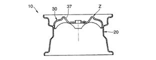
- the disk 30 is an annular protrusion that is used in a general automobile wheel as shown in FIGS. 14 and 15 and that is continuous in the circumferential direction on the disk radial direction outer portion of the inclined portion 37 and protrudes in the wheel axial direction. Does not have Z.
- the hub hole 31 is provided in the central portion of the disk 30 in the wheel radial direction.
- the hub attachment portion 32 is provided around the hub hole 31.
- the hub attachment portion 32 has a flat plate shape or a substantially flat plate shape, and is in a plane orthogonal to or substantially orthogonal to the wheel axial direction.
- the hub mounting portion 32 is provided with a plurality of hub mounting bolt holes 32a. For example, five hub mounting bolt holes 32a are provided at equal intervals in the circumferential direction of the wheel. However, the number of hub mounting bolt holes 32a is not limited to five, may be three, may be four, or may be six or more.
- the disk 30 (wheel 10) is fixed to the hub by inserting hub mounting bolts (both not shown) extending from the hub into the hub mounting bolt holes 32a and screwing hub nuts (not shown) into the hub mounting bolts.
- the hub mounting portion 32 is slightly (around 0.3 mm to 5 mm) around the hub mounting bolt hole 32a.
- a bulging portion 32b bulging in a convex shape is provided on the outer side in the direction.
- an arcuate bulge 32b that connects the hub mounting bolt holes 32a to each other is shown.
- the shape is not limited to this, and other shapes may be used. As shown in FIG.
- the surface on the inner side in the wheel axial direction of the hub attachment portion 32 is between the outer side in the wheel axial direction and the inner side in the wheel axial direction of the disk flange 35 in the wheel axial direction.
- the hub mounting bolt hole 32a may be located at a circumferential position between adjacent spokes 33 as shown in FIG. 2, or may be located at the same circumferential position as the spokes 33 as shown in FIG.
- the spokes 33 extend radially from the hub attachment portion 32 via the inclined portion 37 to the disk flange 35 outward in the wheel radial direction.
- a plurality of spokes 33 are provided.
- five spokes 33 are provided in the wheel circumferential direction.
- the number of spokes 33 is not limited to five, and may be three, four, or six or more as long as a plurality of spokes 33 are provided.
- the number of spokes 33 and the number of hub mounting bolt holes 32a may be different.
- the outer end of the spoke 33 in the wheel radial direction forms an outer peripheral curved surface connection portion R that is folded back inward in the wheel axial direction and connected to the disk flange 35.
- the inner end of the spoke 33 in the radial direction of the wheel forms an inner peripheral curved surface connecting portion r that is folded back inward in the axial direction of the wheel and connected to the inclined portion 37.
- An intermediate portion of the spoke 33 in the wheel radial direction (between the outer peripheral curved surface connection portion R and the inner peripheral curved surface connection portion r in the wheel radial direction) is orthogonal to the wheel axial direction (a direction substantially orthogonal to the wheel axial direction).
- the radial end portions of the spoke 33 in the middle of the wheel radial direction are at substantially the same position in the wheel axial direction.
- the spoke 33 Since the wheel radial direction intermediate portion of the spoke 33 extends in a direction perpendicular to the wheel axial direction, a large bending moment acts on the spoke 33 when a lateral load is applied to the tire (rim 20) during traveling of the vehicle.
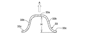
- the spoke 33 is arranged in the wheel circumferential direction (spoke width direction) as shown in FIGS. 2 to 7 and FIGS. 10 to 13.
- the bottom wall portion 33a extends radially from the inclined portion 37 outward in the wheel radial direction.
- the bottom wall portion 33a extends in the wheel circumferential direction (width direction of the spoke 33) in a cross-sectional view when cut along a plane orthogonal to the wheel radial direction.
- the bottom wall portion 33 a may be provided with a wavy portion 33 d, and as shown in FIG. 13, the wavy portion may not be provided.
- the side wall portion 33b extends from both ends in the wheel circumferential direction of the bottom wall portion 33a in a direction away from the bottom wall portion 33a and outward in the wheel axial direction.
- the side wall portion 33b may rise from the bottom wall portion 33a to the outer side in the wheel axial direction as shown in FIG. 10 in a cross-sectional view when cut along a plane orthogonal to the wheel radial direction, but is shown in FIG. In this way, it may rise from the bottom wall 33a inward in the wheel axial direction.
- the direction of arrow A indicates the wheel axis direction outer side. 1 to 9, FIG. 12, FIG. 13, and FIG. 16, the side wall portion 33b is shown standing up from the bottom wall portion 33a in the wheel axial direction.
- the edge portion 33c extends in the circumferential direction of the wheel from the leading end of the side wall portion 33b (the side farther from the bottom wall portion 33a toward the wheel axis direction) in the direction of increasing the width of the spoke 33 (outward in the spoke width direction). ing.
- the spoke 33 is positioned on the outer side in the wheel axial direction from the hub mounting portion 32 and the disk flange 35. Therefore, when the wheel 10 is attached to the vehicle and the vehicle weight is applied, the ground-side spoke 33 to which a load is applied is bent inward in the wheel axial direction. At this time, when the side wall portion 33b extends from the bottom wall portion 33a to the outer side in the wheel axis direction, a tensile stress acts on the edge portion 33c in the wheel radial direction to support the load, so that it is easy to ensure rigidity.
- the width H in the wheel axial direction of the side wall 33 b is the maximum in the vicinity of the inner end in the wheel radial direction of the decorative hole 34 as shown in FIG. 3.
- the maximum width of the side wall 33b in the wheel axial direction width H is in the range of 2 to 20 times the plate thickness of the bottom wall 33a.
- the maximum width of the side wall portion 33b in the wheel axial direction width H is desirably in the range of 4 to 10 times the plate thickness of the bottom wall portion 33a.
- the width (width in the wheel circumferential direction) B1 of the narrowest portion of the spoke 33 is narrower than the width (width in the circumferential direction of the wheel) B2 of the widest portion of the decorative hole 34, as shown in FIG.
- the decoration hole 34 has an elliptical shape when viewed from the outside in the axial direction.
- the shape of the decorative hole 34 viewed from the outside in the axial direction is not limited to an elliptical shape, and may be a triangular shape, a trapezoidal shape, or other shapes.
- a decorative hole 34 is located between the spokes 33 adjacent to each other in the wheel circumferential direction.
- the width of the spoke 33 in the circumferential direction of the wheel is the narrowest in the portion in the wheel radial direction that is the same as the portion of the decorative hole 34 on both sides in the circumferential direction of the wheel where the width in the circumferential direction of the wheel is the largest.
- the same number of decoration holes 34 as the number of spokes 33 are provided between adjacent spokes 33, 33 at equal intervals in the circumferential direction of the wheel.
- the wheel radial direction outer end portion 34 a of the decoration hole 34 is the innermost in the disk axial direction of the decoration hole 34. 3 to 7 and 13, the wheel radial outer end portion 34a of the decorative hole 34 reaches the disk flange 35 and is directly connected to the disk flange 35 extending linearly in the wheel axial direction in a sectional view. .
- FIGS. 1 the wheel radial direction outer end portion 34 a of the decoration hole 34
- the diameter of the transition portion 35 a on the decorative hole 34 side is larger than the diameter on the disk flange 35 side
- the wheel radial outer end portion 34 a on the outer peripheral portion of the decorative hole 34 is larger than the diameter of the disk flange 35
- the outer peripheral portion 34 a in the radial direction of the wheel is radially outward from the outer peripheral surface of the disk flange 35.
- the radius difference (a stepped amount) d1 between the outer peripheral surface of the disk flange 35 and the outer peripheral surface of the transition portion 35a is based on the plate thickness of the disk flange 35 (for example, 5 mm, more generally 2.5 mm to 8 mm). Small is desirable. More preferably, the stepped amount d1 is 0.5 mm or more and less than the plate thickness of the disk flange 35. When the stepped amount d1 is 0.5 mm or more and less than the plate thickness of the disk flange 35, the rigidity of the disk flange 35 is improved, and as a result, the durability of the wheel 10 is improved.
- the stepped portion of the transition part 35a facilitates positioning of the rim 20 and the disk 30 in the wheel axis direction when the rim 20 and the disk 30 are assembled. If the stepped amount d1 is smaller than 0.5 mm, the effect of positioning in the wheel axis direction is reduced. Although the stepped amount d1 may be larger than the plate thickness of the disc flange 35, the formability of the disc 30 is deteriorated.
- the diameter of the transition portion 35 a on the decorative hole 34 side is smaller than the diameter on the disk flange 35 side, and the wheel radial outer end portion 34 a on the outer peripheral portion of the decorative hole 34 is smaller than the diameter of the disk flange 35.
- a wheel radial outer end portion 34 a of the outer peripheral portion of the hole 34 is located radially inward from the outer peripheral surface of the disk flange 35.
- the radius difference (a stepped amount) d2 between the outer peripheral surface of the disc flange 35 and the outer peripheral surface of the transition portion 35a is based on the plate thickness of the disc flange 35 (for example, 5 mm, more generally 2.5 mm to 8 mm). Small is desirable. More preferably, the stepped amount d2 is 0.5 mm or more and less than the plate thickness of the disk flange 35.
- the stepped amount d2 is 0.5 mm or more and less than the plate thickness of the disk flange 35, the rigidity of the disk flange 35 is improved, and as a result, the durability of the wheel 10 is improved.
- the diameter of the transition portion 35a is smaller than the diameter of the disk flange 35, the rim 20 and the disk 30 can be easily fitted together when the rim 20 and the disk 30 are assembled.
- the stepped amount d2 is smaller than 0.5 mm, the fitting between the rim 20 and the disc 30 is an interference fit, so that the disc 30 is deformed so that the stepped portion is reduced, so that the stepped effect is obtained. Less.
- the stepped amount d2 may be larger than the thickness of the disk flange 35. However, the moldability of the disk 30 deteriorates, and the decorative hole 34 becomes smaller, resulting in a decrease in design.
- the disc flange 35 is located at the outer end in the wheel radial direction of the disc 30 (in the case of the disc 30 shown in FIG. 8, in the vicinity of the outer end in the wheel radial direction of the disc 30). As shown in FIG. 4, the disk flange 35 connects the spokes 33, 33 adjacent to each other in the circumferential direction of the wheel in the circumferential direction of the wheel in the radial direction of the wheel or in the vicinity thereof. As shown in FIG. 3, the disk flange 35 extends linearly in the wheel axial direction in a cross-sectional view orthogonal to the wheel circumferential direction.
- the axial width (minimum portion) B3 of the transition portion 35a between the decorative hole 34 and the disk flange 35 shown in FIGS. 8 and 9 and the axial width (minimum portion) B4 of the disk flange 35 adjacent to the decorative hole 34 are shown.
- the total width (B3 + B4) is smaller than the width B2 (see FIGS. 2, 12, and 16) of the widest portion of the decorative hole 34 in the wheel circumferential direction. Further, the total width of the axial width (minimum portion) B3 of the transition portion 35a between the decorative hole 34 and the disk flange 35 and the axial width (minimum portion) B4 of the disk flange 35 adjacent to the decorative hole 34.
- the axial width (minimum portion) B4 of the disc flange 35 adjacent to the decoration hole 34 is the width of the widest portion of the decoration hole 34 in the wheel circumferential direction. It is narrower than the width B2 (see FIGS. 2, 12, and 16). Further, the axial width (minimum portion) B4 of the disk flange 35 adjacent to the decoration hole 34 is smaller than the width (width in the circumferential direction of the wheel) B1 of the spoke 33 (see FIGS. 2, 12, and 16). Is too narrow.
- the disc flange 35 is fitted into the drop portion 24 of the rim 20 and joined (fixed or welded) to the drop portion 24.
- the disk flange 35 may be fitted and joined to a place other than the drop part 24 such as the inner bead sheet part 22 or the outer bead sheet part 26 of the rim 20.
- the disk flange 35 may be joined to the rim 20 only by the first portion 35b (see FIG. 4) located on the inner side in the wheel axis direction of the decorative hole 34, and is a portion other than the first portion 35b, which will be described later. Only the second portion 35c (see FIG.
- the welding position W when the joining is welding is the axially inner side of the first part 35b or the second part 35c (see FIG. 3), or the axially outer side of the first part 35b or the second part 35c. It may be welded. Furthermore, it may be welded both on the outside in the axial direction and on the inside.
- the disc flange 35 When the disc flange 35 is joined to the rim 20 by welding at the first portion 35b, the disc flange 35 is welded at a position with less rigidity as compared with the case where the disc flange 35 is joined at the position of the disc flange 35 on the outer peripheral side of the spoke 33. As a result, the stress concentration in the welded portion is alleviated and the fatigue durability of the wheel 10 is improved.
- the disc flange 35 is joined to the rim 20 by welding at the second portion 35c, even if the decorative hole 34 is formed prior to the press forming of the portion that becomes the disc flange 35, the second portion 35c. The wheel axial position after press molding is stable, and welding can be performed reliably.
- the disk flange 35 has a non-contact portion 36 that is in non-contact with the inner peripheral surface of the rim 20 at a portion extending outwardly in the wheel radial direction of the center line in the width direction of the spoke 33.
- the non-contact part 36 may consist of (i) a notch 36a provided in the wheel radial direction outside extension part of the width direction center line of the spoke 33 of the disk flange 35 (Invention Example 1), (ii) )
- the disk flange 35 may be formed of a recess 36b that is recessed from the inner peripheral surface of the rim 20 to the inner side in the wheel radial direction at a portion extending radially outward from the center line in the width direction of the spoke 33 (Example 2 of the present invention). .
- the same number of non-contact portions 36 as the spokes 33 are provided.
- the disk flange 35 extends in the wheel circumferential direction except for the non-contact portion 36. Since the disc flange 35 has the non-contact portion 36, it does not continuously extend in the wheel circumferential direction (not in a ring shape).
- the inclined portion 37 is a substantially cylindrical portion on the outer periphery of the hub attachment portion 32, and connects the bottom wall portion 33 a of the spoke 33 and the hub attachment portion 32.
- the inclined portion 37 extends from the outer peripheral portion 32c of the hub attachment portion 32 to the wheel radial direction outer side and the wheel axial direction outer side.
- the projecting portion 38 protrudes from the decorative hole 34 in the wheel radial direction inner side in the wheel axial direction and in the wheel radial direction inner side, and is connected to the inclined portion 37.
- the protruding portion 38 may be directly connected to the hub mounting portion 32 beyond the inclined portion 37.
- the arrangement of the hub mounting bolt holes 32a is fixed at a position corresponding to the spoke 33. .
- the disk flange 35 has the non-contact portion 36 that is in non-contact with the inner peripheral surface of the rim 20 at the radially outward extension portion of the spoke 33 in the width direction center line.
- the rigidity difference between the position where the decorative hole 34 is provided on the disk 30 and the position where the spoke 33 is provided on the disk 30 in the circumferential direction of the wheel can be reduced as compared with the related art.
- the fitting strength between the disk flange 35 at the position where the spokes 33 of the disk 30 are provided in the wheel circumferential direction and the drop portion 24 of the rim 20 can be reduced. Therefore, the difference between the position where the decorative hole 34 of the disk flange 35 is provided and the fitting strength between the position where the spoke 33 of the disk flange 35 is provided and the drop portion 24 of the rim 20 can be reduced.
- the durability of the wheel can be increased and the wheel runout accuracy can be improved as compared with the conventional case.
- the force transmission from the spoke 33 to the disk flange 35 corresponding to the position where the decorative holes 34 on both sides of the spoke are provided becomes smooth, and the stress concentration can be reduced.
- the disk flange 35 has the non-contact portion 36, so that an excessive force is not applied to the fitting portion of the rim 20 with the drop portion 24.
- the outer portion of the disk flange 35 connected to the outer side in the radial direction of the spoke 33 and the drop portion 24 of the rim 20 are not in contact with each other, it is difficult to be affected by the uneven shape of the disk flange 35 connected to the outer side in the radial direction of the spoke 33. Therefore, it is possible to prevent the durability of the wheel and the runout accuracy of the wheel from being lowered.
- the maximum width H in the wheel axial direction width of the side wall 33b of the spoke 33 is in the range of 2 to 20 times the plate thickness of the bottom wall 33a of the spoke 33, the rigidity and durability of the disk 30 and molding Can be secured.
- the transition portion 35a is provided between the decorative hole 34 and the disk flange 35, the rigidity of the disk flange 35 can be improved, and the assembly of the disk 30 with the rim 20 is facilitated.
- the non-contact portion 36 includes a notch 36 a provided on the outer side of the disk flange 35 in the radial direction of the wheel radial direction of the center line in the width direction of the spoke 33, and the notch 36 a is the bottom wall of the spoke 33.
- the part 33a is reached. Therefore, as shown in FIGS. 2 and 12, the non-contact portion 36 is seen as a gap in the front view of the wheel 10.
- the wheel axial direction length of the deepest part of the notch 36a is larger than the wheel axial direction length of the disc flange 35. However, if the notch 36a reaches the bottom wall 33a of the spoke 33, the length in the wheel axis direction of the deepest portion of the notch 36a does not necessarily need to be larger than the length in the wheel axis direction of the disc flange 35.
- the shape of the notch 36a in a front view may be a substantially rectangular shape as shown in FIG. 4, or may be a substantially semicircular shape (single arc shape) as shown in FIG. As shown in FIG. 7, it may be a substantially semi-oval shape (a shape formed by a plurality of arcs and straight lines), as shown in FIG.
- the shape may also be
- the maximum width B5 of the notch 36a in the circumferential direction of the wheel is preferably larger than the plate thickness of the disc flange 35 and smaller than the width B6 in the circumferential direction of the wheel where the spoke 33 is connected to the disc flange 35.
- the maximum width B5 of the notch 36a in the wheel circumferential direction is more preferably smaller than the width B1 of the narrowest portion of the spoke 33 in the wheel circumferential direction. If the maximum width B5 of the notch 36a in the circumferential direction of the wheel is too large, the connection strength between the spoke 33 and the disk flange 35 is lowered and the durability is lowered.
- the notch 36a may be provided at the same time in the process of forming the hub hole 31, the hub mounting bolt hole 32a, and the decorative hole 34, or may be provided at a stage after the disk 30 is formed. It may be provided at the stage of the plate material before molding.
- the portion of the notch 36a having the largest width in the circumferential direction of the wheel may be the inner end in the axial direction of the disc flange 35 (the open end of the notch 36a), and the portion that enters the outer side in the axial direction from the inner end in the axial direction of the disc flange 35. But you can.
- the non-contact part 36 can be provided by providing the notch 36a. Since the length of the notch 36a in the wheel axis direction is larger than the length of the disc flange 35 in the wheel axis direction, or the notch 36a reaches the bottom wall portion 33a of the spoke 33, the notch 36a is provided. Thus, the non-contact portion 36 can be reliably brought into non-contact with the inner peripheral surface of the rim 20. Further, by providing the notch 36a, the weight of the disk 30 (wheel 10) can be reduced as compared with the case where the notch 36a is not provided. Further, when the notch 36a is provided simultaneously in the process of forming the hub hole 31 and the like, the notch 36a can be provided without requiring a new separate process.
- the non-contact portion 36 is an extension portion of the disk flange 35 on the outer side in the wheel radial direction of the center line in the width direction of the spoke 33, and from the recess 36 b that is recessed from the inner peripheral surface of the rim 20 Become.
- the recess 36b is recessed radially inward corresponding to the outer peripheral side and the inner peripheral side of the disk flange 35, but the outer peripheral side is recessed because the thickness of the disk flange 35 is locally reduced. May be formed.
- the shape of the recess 36b in a front view may be a substantially rectangular shape, a substantially semicircular shape (single arc shape), or a substantially semi-oval shape (a plurality of arcs and straight lines).
- the shape may be a shape formed by the following: a wide, substantially rectangular shape, or any other shape.
- the wheel axis direction length of the deepest part of the recess 36b is larger than the wheel axis direction length of the disk flange 35.
- the length in the wheel axis direction of the deepest portion of the recess 36 b does not necessarily need to be larger than the length in the wheel axis direction of the disk flange 35.
- the recess 36b may be provided simultaneously with the formation of the disk 30 or may be provided at a stage after the disk 30 is formed.
- the non-contact part 36 can be provided by providing the recessed part 36b.
- the recessed part 36b is provided simultaneously with the shaping
Abstract
Description
(i)ディスクフランジがリング状で、かつ飾り穴が大きくディスクフランジ付近まであるため、ホイール周方向でディスクの、飾り穴が設けられる位置とスポークが設けられる位置との剛性差が大きい。そのため、ホイールが回転しながら荷重を受けると、ディスクとリムに捩れ変形などが生じやすい。ディスクとリムに捩れ変形が生じると、リムとディスクの継ぎ手強度が低下してホイールの耐久性が低くなってしまう。
(ii)ディスクフランジがリング状で、かつ飾り穴が大きくディスクフランジ付近まであるため、ホイール周方向でディスクの、飾り穴が設けられる位置とスポークが設けられる位置との剛性差が大きい。そのため、ディスクをリムに嵌入する時にリムが変形してしまう(歪んでしまう)おそれがある。リムが変形すると、ホイールの振れ精度(リムの振れ精度)が低下してしまう。
(iii)スポークの曲げ変形抑制および耐久性向上のため、スポークが底壁部と側壁部と縁部とから構成されている。そのため、ディスクフランジをプレス加工により絞り成形すると、スポークの径方向外側につながるディスクフランジの外形が凸凹形状となりやすい。そのため、ホイールの耐久性およびホイールの振れ精度が低下してしまう。 However, the conventional automobile wheel has the following problems.
(I) Since the disk flange is ring-shaped and the decoration hole is large and close to the disk flange, the difference in rigidity between the position where the decoration hole is provided and the position where the spoke is provided on the disk in the circumferential direction of the wheel is large. Therefore, if the wheel receives a load while rotating, the disk and the rim are likely to be twisted and deformed. When the disk and the rim are twisted, the joint strength between the rim and the disk is lowered, and the durability of the wheel is lowered.
(Ii) Since the disk flange is ring-shaped and the decoration hole is large and close to the disk flange, the rigidity difference between the position where the decoration hole is provided and the position where the spoke is provided is large in the circumferential direction of the wheel. Therefore, the rim may be deformed (distorted) when the disc is inserted into the rim. When the rim is deformed, the wheel runout accuracy (rim runout accuracy) decreases.
(Iii) The spoke is composed of a bottom wall portion, a side wall portion, and an edge portion in order to suppress the bending deformation of the spoke and improve durability. Therefore, when the disk flange is drawn by press working, the outer shape of the disk flange connected to the outside in the radial direction of the spoke tends to be uneven. Therefore, the durability of the wheel and the runout accuracy of the wheel are reduced.
(1) (a)ドロップ部を有するリムと、
(b)ホイール半径方向外側に放射状に延びる複数のスポークと、ホイール半径方向外側端部に位置し前記複数のスポーク部のホイール半径方向外側端部をホイール周方向に連結するディスクフランジと、を備え、前記スポーク間に飾り穴が形成されているディスクと、
を有し、前記ドロップ部と前記ディスクフランジ部とが接合する自動車用ホイールであって、
前記ディスクフランジは、前記スポークの幅方向中心線のホイール半径方向外側延長部位に、前記リムの内周面と非接触の非接触部を有する、自動車用ホイール。
(2) 前記非接触部は、前記ディスクフランジの、前記スポークの幅方向中心線のホイール半径方向外側延長部位に設けられる切欠きからなる、(1)記載の自動車用ホイール。
(3) 前記非接触部は、前記ディスクフランジの、前記スポークの幅方向中心線のホイール半径方向外側延長部位で、前記リムの内周面からホイール半径方向内側に凹む凹部からなる、(1)記載の自動車用ホイール。 The present invention for achieving the above object is as follows.
(1) (a) a rim having a drop portion;
(B) a plurality of spokes extending radially outward in the radial direction of the wheel, and a disk flange located at the outer radial end of the wheel and connecting the outer radial ends of the multiple spokes in the circumferential direction of the wheel. , A disc in which a decorative hole is formed between the spokes;
An automotive wheel in which the drop portion and the disk flange portion are joined,
The disk flange has a non-contact portion that is in non-contact with the inner peripheral surface of the rim, at a portion extending outward in the wheel radial direction of the center line in the width direction of the spoke.
(2) The automotive wheel according to (1), wherein the non-contact portion is formed by a notch provided in a wheel radial direction outside extension portion of a center line of the spoke in the width direction of the disc flange.
(3) The non-contact portion is a portion of the disc flange that extends outward in the wheel radial direction of the center line in the width direction of the spoke, and includes a recess that is recessed inward in the wheel radial direction from the inner peripheral surface of the rim. The automotive wheel described.
上記(2)の自動車用ホイールによれば、切欠きを設けることで非接触部を設けることができ、ホイールの軽量化を図ることができる。
上記(3)の自動車用ホイールによれば、凹部を設けることで製造工程を増やすことなく非接触部を設けることができる。 According to the vehicle wheel of (1) above, the disc flange has a non-contact portion that is in non-contact with the inner peripheral surface of the rim at the radially outward extension portion of the spoke in the width direction of the center line. Compared to the case where the disk is not provided (conventional), the rigidity of the disk at the position where the spoke is provided in the circumferential direction of the wheel can be reduced. Therefore, the difference in rigidity between the position where the decorative hole is provided and the position where the spoke is provided on the disc in the circumferential direction of the wheel can be reduced as compared with the conventional case. As a result, the durability of the wheel can be increased and the wheel runout accuracy can be improved as compared with the conventional case.
According to the vehicle wheel of (2) above, the non-contact portion can be provided by providing the notch, and the weight of the wheel can be reduced.
According to the automobile wheel of (3) above, the non-contact portion can be provided without increasing the manufacturing process by providing the recess.
本発明実施例1と本発明実施例2にわたって共通する部分には、本発明実施例1と実施例2にわたって同じ符号を付してある。
まず、本発明実施例1と実施例2にわたって共通する部分を説明する。 1 to 13 show a vehicle wheel according to Embodiment 1 of the present invention. FIGS. 14 and 15 show a general vehicle wheel different from the present invention. FIG. 16 shows the present invention. The wheel for motor vehicles of Example 2 is shown. However, FIGS. 8 to 11 are also applicable to the second embodiment of the present invention.
Portions common to the first embodiment and the second embodiment of the present invention are denoted by the same reference numerals throughout the first and second embodiments of the present invention.
First, parts common to the first and second embodiments of the present invention will be described.
ハブ取付け部32は、ハブ穴31の周囲に設けられている。ハブ取付け部32は、平板状または略平板状であり、ホイール軸方向と直交またはほぼ直交する平面内にある。ハブ取付け部32にはハブ取付けボルト穴32aが複数設けられている。ハブ取付けボルト穴32aは、ホイール周方向に等間隔にたとえば5個設けられている。ただし、ハブ取付けボルト穴32aの数は、5個に限定されるものではなく、3個であってもよく、4個であってもよく、6個以上であってもよい。ハブから延びてくるハブ取付けボルト(両方共に図示略)をハブ取付けボルト穴32aに挿通し、ハブ取付けボルトに図示略のハブナットを螺合することにより、ディスク30(ホイール10)はハブに固定される。図2に示すように、ハブ取付け部32には、ハブ取付け部32の剛性向上、耐久性向上などのために、ハブ取付けボルト穴32aの周囲で僅か(0.3mm~5mm程度)にホイール軸方向外側に凸状に膨らんだ膨らみ部32bが、設けられている。実施例においては、互いのハブ取付けボルト穴32aをつなぐ円弧状の膨らみ部32bを示す。ただし、これに限らず他の形状でも良い。
ハブ取付け部32のホイール軸方向内側の面は、図3に示すように、ホイール軸方向で、ディスクフランジ35のホイール軸方向外側とホイール軸方向内側との間にある。
ハブ取付けボルト穴32aは、図2に示すように隣接するスポーク33の間の周方向位置に位置してもよく、図12に示すようにスポーク33と同じ周方向位置に位置しても良い。 As shown in FIG. 2, the
The
As shown in FIG. 3, the surface on the inner side in the wheel axial direction of the
The hub mounting
側壁部33bのホイール軸方向幅Hは、ホイール10の剛性を効果的に向上させるために、図3に示すように、飾り穴34のホイール半径方向内側端部の近傍部分で最大である。側壁部33bのホイール軸方向幅Hの最大幅は、底壁部33aの板厚の2倍から20倍の範囲内にある。なお、側壁部33bのホイール軸方向幅Hの最大幅は、底壁部33aの板厚の4倍から10倍の範囲内にあることが望ましい。その理由は、ホイール10の剛性も高く、ディスク30の成形性も良いからである。
スポーク33の幅の最も狭い部分の幅(ホイール周方向の幅)B1は、図2に示すように、飾り孔34の最も広い部分の幅(ホイール周方向の幅)B2よりも狭い。 As shown in FIGS. 3 and 13, the
In order to effectively improve the rigidity of the
The width (width in the wheel circumferential direction) B1 of the narrowest portion of the
ホイール周方向に隣り合うスポーク33,33の間に、飾り穴34が位置している。スポーク33のホイール周方向の幅は、ホイール周方向両側の飾り穴34のホイール周方向の幅が最大の部位と同じホイール半径方向の部位で最も狭い。
飾り穴34は、隣り合うスポーク33、33の間に、ホイール周方向に等間隔に、スポーク33の数と同数設けられている。図3および図13に示すように、飾り穴34のホイール半径方向外側端部分34aは、飾り穴34のうち最もディスク軸方向内側になっている。図3ないし図7および図13では、飾り穴34の、ホイール半径方向外側端部分34aは、ディスクフランジ35に達し、断面視でホイール軸方向に直線状に延びるディスクフランジ35に直接接続している。ただし、図8および図9に示すように、飾り穴34と断面視でホイール軸方向に直線状に延びるディスクフランジ35との間に、テーパ状または段付き状の移行部35aがあっても良い。
図8では、移行部35aの飾り穴34側の直径がディスクフランジ35側の直径より大きく、飾り穴34の外周部のホイール半径方向外側端部分34aがディスクフランジ35の直径より大きく、飾り穴34の外周部のホイール半径方向外側端部分34aが、ディスクフランジ35の外周面より半径方向外側にある。ディスクフランジ35の外周面と移行部35aの外周面との半径の差(段付きの量)d1は、ディスクフランジ35の板厚(例えば5mm、さらに一般的には、2.5mm~8mm)より小さいことが望ましい。さらに望ましくは、段付きの量d1は、0.5mm以上でディスクフランジ35の板厚以下が望ましい。段付きの量d1が0.5mm以上でディスクフランジ35の板厚以下であると、ディスクフランジ35の剛性が向上し、結果としてホイール10の耐久性が向上する。また、移行部35aの段付き部分により、リム20とディスク30の組付け時にリム20とディスク30とのホイール軸方向の位置決めが容易となる。段付きの量d1が0.5mmより小さいとホイール軸方向の位置決めの効果が少なくなってしまう。段付きの量d1がディスクフランジ35の板厚より大きくてもよいが、ディスク30の成形性が悪化する。
また、図9では、移行部35aの飾り穴34側の直径がディスクフランジ35側の直径より小さく、飾り穴34の外周部のホイール半径方向外側端部分34aがディスクフランジ35の直径より小さく、飾り穴34の外周部のホイール半径方向外側端部分34aが、ディスクフランジ35の外周面より半径方向内側にある。ディスクフランジ35の外周面と移行部35aの外周面との半径の差(段付きの量)d2は、ディスクフランジ35の板厚(例えば5mm、さらに一般的には、2.5mm~8mm)より小さいことが望ましい。さらに望ましくは、段付きの量d2は、0.5mm以上でディスクフランジ35の板厚以下が望ましい。段付きの量d2が0.5mm以上でディスクフランジ35の板厚以下であると、ディスクフランジ35の剛性が向上し、結果としてホイール10の耐久性が向上する。また、移行部35aの直径がディスクフランジ35の直径より小さくなっているため、リム20とディスク30の組付け時にリム20とディスク30との嵌合が容易となる。段付きの量d2が0.5mmより小さいと、リム20とディスク30との嵌合が締り嵌めとなっているため、段付きが少なくなるようにディスク30が変形して、そのため段付きの効果が少なくなる。段付きの量d2がディスクフランジ35の板厚より大きくてもよいが、ディスク30の成形性が悪化するとともに、飾り穴34が小さくなり意匠性が低下する。 As shown in FIG. 2, the
A
The same number of decoration holes 34 as the number of
In FIG. 8, the diameter of the
In FIG. 9, the diameter of the
図3および図13に示すように移行部を有しない場合、飾り穴34に隣接するディスクフランジ35の軸方向幅(最小部分)B4は、飾り孔34のホイール周方向の幅の最も広い部分の幅B2(図2、図12、図16参照)よりも狭い。さらに、飾り穴34に隣接するディスクフランジ35の軸方向幅(最小部分)B4は、スポーク33の最も狭い部分の幅(ホイール周方向の幅)B1(図2、図12、図16参照)よりも狭い。 The axial width (minimum portion) B3 of the
3 and FIG. 13, when there is no transition portion, the axial width (minimum portion) B4 of the
ディスクフランジ35は、飾り穴34のホイール軸方向内側に位置する第1の部分35b(図4参照)のみでリム20に接合されていてもよく、第1の部分35b以外の部分であり後述する非接触部36のホイール周方向両側に位置する部分である第2の部分35c(図4参照)のみでリム20に接合されていてもよく、第1の部分35bと第2の部分35cの両方でリム20に接合されていてもよい。また接合が溶接の場合の溶接位置Wは、第1の部分35bあるいは第2の部分35cの軸方向内側(図3参照)、または第1の部分35bあるいは第2の部分35cの軸方向外側で溶接されていてもよい。さらに軸方向外側と内側の両方で溶接されていてもよい。
ディスクフランジ35が第1の部分35bでリム20に溶接にて接合される場合、スポーク33の外周側のディスクフランジ35の位置で溶接にて接合される場合に比べて剛性の小さい位置で溶接されることになり、溶接部の応力集中が緩和され、ホイール10の疲労耐久性が向上する。
ディスクフランジ35が第2の部分35cでリム20に溶接にて接合される場合、飾り穴34をディスクフランジ35になる部分のプレス成形より先に形成した場合であっても、第2の部分35cのプレス成形後のホイール軸方向位置は安定しており、溶接を確実に行なうことができる。 In FIG. 3, the
The
When the
When the
本発明実施例では、ディスクフランジ35が、スポーク33の幅方向中心線のホイール半径方向外側延長部位に、リム20の内周面と非接触の非接触部36を有するため、非接触部36を有していない場合(従来)に比べて、ホイール周方向でディスク30の、スポーク33が設けられる位置の剛性(ディスクフランジ35の対象部位に対して、ディスクフランジ35の対象部位を除くディスク30全体が、ディスクフランジ35の対象部位の板材を板厚方向に曲げる場合の剛性、面剛性)を低下させることができる。そのため、ホイール周方向でディスク30の、飾り穴34が設けられる位置とスポーク33が設けられる位置との剛性差を、従来に比べて小さくできる。また、ホイール周方向でディスク30の、スポーク33が設けられている位置のディスクフランジ35とリム20のドロップ部24との嵌合強度を低下させることができる。そのため、ディスクフランジ35の飾り穴34が設けられている位置と、ディスクフランジ35のスポーク33が設けられている位置とリム20のドロップ部24との嵌合強度との差を小さくできる。その結果、従来に比べて、ホイールの耐久性を高めることができ、ホイールの振れ精度を向上させることができる。また、スポーク33からスポーク両側の飾り穴34が設けられる位置に対応するディスクフランジ35への力の伝達がスムーズになり応力集中を軽減できる。 Here, an operation common to the first and second embodiments of the present invention will be described.
In the embodiment of the present invention, the
本発明実施例1では、非接触部36が、ディスクフランジ35の、スポーク33の幅方向中心線のホイール半径方向外側延長部位に設けられる切欠き36aからなり、切欠き36aがスポーク33の底壁部33aに達している。そのため、図2および図12に示すように、ホイール10の正面視で非接触部36が隙間として見えている。 [Example 1] (FIGS. 1 to 13)
In the first embodiment of the present invention, the
切欠き36aの正面視での形状は、図4に示すように略矩形状であってもよく、図5に示すように、略半円形(単一円弧形状)であってもよく、図6に示すように略半長円形(複数の円弧と直線とで形成される形状)であってもよく、図7に示すように図4に比べて幅広の略矩形状であってもよく、その他の形状であってもよい。切欠き36aのホイール周方向の最大幅B5は、ディスクフランジ35の板厚より大きく、スポーク33がディスクフランジ35と接続する部位のホイール周方向の幅B6より小さいことが望ましい。切欠き36aのホイール周方向の最大幅B5は、スポーク33の最も狭い部分のホイール周方向の幅B1より小さいことがさらに望ましい。
切欠き36aのホイール周方向の最大幅B5が大きすぎると、スポーク33とディスクフランジ35との接続強度が低下して耐久性が下がる。切欠き36aのホイール周方向の最大幅B5が小さすぎると、切欠き36aに応力が集中して耐久性が下がる。
切欠き36aは、ハブ穴31、ハブ取付けボルト穴32aおよび飾り穴34を形成する工程で同時に設けられていてもよく、ディスク30を成形した後の段階で設けられていてもよく、ディスク30を成形する前の板材の段階で設けられていてもよい。切欠き36aのホイール周方向の幅が最大の部位は、ディスクフランジ35の軸方向内側端(切欠き36aの開口端)でもよく、ディスクフランジ35の軸方向内側端より軸方向外側に入った部位でもよい。 The wheel axial direction length of the deepest part of the
The shape of the
If the maximum width B5 of the
The
切欠き36aを設けることで非接触部36を設けることができる。
切欠き36aのホイール軸方向長さが、ディスクフランジ35のホイール軸方向長さより大となっているため、あるいは切欠き36aがスポーク33の底壁部33aに達しているため、切欠き36aを設けることで、非接触部36を確実にリム20の内周面と非接触にすることができる。
また、切欠き36aを設けることで、切欠き36aを設けない場合に比べてディスク30(ホイール10)の軽量化を図ることができる。
また、切欠き36aがハブ穴31等を形成する工程で同時に設けられる場合、新たな別工程を要することなく切欠き36aを設けることができる。 In the embodiment 1 of the present invention, in addition to the operations common to the embodiments 1 and 2 of the present invention, the following specific operations can be obtained.
The
Since the length of the
Further, by providing the
Further, when the
本発明実施例2では、非接触部36が、ディスクフランジ35の、スポーク33の幅方向中心線のホイール半径方向外側延長部位で、リム20の内周面からホイール半径方向内側に凹む凹部36bからなる。図16の例では、凹部36bはディスクフランジ35の外周側と内周側が対応して径方向内側に凹んでいるが、ディスクフランジ35の厚みが局部的に薄くなることで外周側が凹んで凹部36bを形成してもよい。 [Example 2] (FIG. 16)
In the second embodiment of the present invention, the
凹部36bの最も深い部位のホイール軸方向長さは、ディスクフランジ35のホイール軸方向長さより大となっている。ただし、凹部36bがスポーク33の底壁部33aに達していれば、凹部36bの最も深い部位のホイール軸方向長さは必ずしもディスクフランジ35のホイール軸方向長さより大でなくてもよい。
凹部36bは、ディスク30の成形と同時に設けられていてもよく、ディスク30を成形した後の段階で設けられていてもよい。 Although not illustrated, the shape of the
The wheel axis direction length of the deepest part of the
The
凹部36bを設けることで非接触部36を設けることができる。
凹部36bがディスク30の成形と同時に設けられる場合、新たな別工程を要することなく凹部36bを設けることができる。 In the embodiment 2 of the present invention, in addition to the operations common to the embodiments 1 and 2 of the present invention, the following specific operations can be obtained.
The
When the recessed
20 リム
21 内側フランジ部
22 内側ビードシート部
23 内側サイドウォール部
24 ドロップ部
25 外側サイドウォール部
26 外側ビードシート部
27 外側フランジ部
30 ディスク
31 ハブ穴
32 ハブ取付け部
32a ハブ取付けボルト穴
33 スポーク
34 飾り穴
35 ディスクフランジ
35a 移行部
36 非接触部
36a 切欠き
36b 凹部
37 傾斜部
38 突起部 DESCRIPTION OF
Claims (3)
- (a)ドロップ部を有するリムと、
(b)ホイール半径方向外側に放射状に延びる複数のスポークと、ホイール半径方向外側端部に位置し前記複数のスポーク部のホイール半径方向外側端部をホイール周方向に連結するディスクフランジと、を備え、前記スポーク間に飾り穴が形成されているディスクと、
を有し、前記ドロップ部と前記ディスクフランジ部とが接合する自動車用ホイールであって、
前記ディスクフランジは、前記スポークの幅方向中心線のホイール半径方向外側延長部位に、前記リムの内周面と非接触の非接触部を有する、自動車用ホイール。 (A) a rim having a drop portion;
(B) a plurality of spokes extending radially outward in the radial direction of the wheel, and a disk flange located at the outer radial end of the wheel and connecting the outer radial ends of the multiple spokes in the circumferential direction of the wheel. , A disc in which a decorative hole is formed between the spokes;
An automotive wheel in which the drop portion and the disk flange portion are joined,
The disk flange has a non-contact portion that is in non-contact with the inner peripheral surface of the rim, at a portion extending outward in the wheel radial direction of the center line in the width direction of the spoke. - 前記非接触部は、前記ディスクフランジの、前記スポークの幅方向中心線のホイール半径方向外側延長部位に設けられる切欠きからなる、請求項1記載の自動車用ホイール。 The automobile wheel according to claim 1, wherein the non-contact portion is formed by a notch provided in an outer radial extension portion of the disc flange in the center line in the width direction of the spoke.
- 前記非接触部は、前記ディスクフランジの、前記スポークの幅方向中心線のホイール半径方向外側延長部位で、前記リムの内周面からホイール半径方向内側に凹む凹部からなる、請求項1記載の自動車用ホイール。 2. The automobile according to claim 1, wherein the non-contact part is a recessed part recessed from the inner peripheral surface of the rim to the inner side in the wheel radial direction at a portion extending outwardly in the wheel radial direction of the center line of the spoke in the width direction of the spoke. Wheel.
Priority Applications (3)
| Application Number | Priority Date | Filing Date | Title |
|---|---|---|---|
| CN201080012232.9A CN102356003B (en) | 2009-03-17 | 2010-03-16 | Wheel for automobile |
| DE112010001192.3T DE112010001192B4 (en) | 2009-03-17 | 2010-03-16 | VEHICLE WHEEL |
| US13/228,490 US8646851B2 (en) | 2009-03-17 | 2011-09-09 | Vehicle wheel |
Applications Claiming Priority (4)
| Application Number | Priority Date | Filing Date | Title |
|---|---|---|---|
| JP2009-063759 | 2009-03-17 | ||
| JP2009063759 | 2009-03-17 | ||
| JP2010057767A JP5612339B2 (en) | 2009-03-17 | 2010-03-15 | Automotive wheel |
| JP2010-057767 | 2010-03-15 |
Related Child Applications (1)
| Application Number | Title | Priority Date | Filing Date |
|---|---|---|---|
| US13/228,490 Continuation US8646851B2 (en) | 2009-03-17 | 2011-09-09 | Vehicle wheel |
Publications (1)
| Publication Number | Publication Date |
|---|---|
| WO2010107008A1 true WO2010107008A1 (en) | 2010-09-23 |
Family
ID=42739668
Family Applications (1)
| Application Number | Title | Priority Date | Filing Date |
|---|---|---|---|
| PCT/JP2010/054379 WO2010107008A1 (en) | 2009-03-17 | 2010-03-16 | Wheel for automobile |
Country Status (5)
| Country | Link |
|---|---|
| US (1) | US8646851B2 (en) |
| JP (1) | JP5612339B2 (en) |
| CN (1) | CN102356003B (en) |
| DE (1) | DE112010001192B4 (en) |
| WO (1) | WO2010107008A1 (en) |
Cited By (3)
| Publication number | Priority date | Publication date | Assignee | Title |
|---|---|---|---|---|
| ITTO20110190A1 (en) * | 2011-03-03 | 2012-09-04 | Mw Italia S P A | WHEEL FOR VEHICLES |
| WO2012153577A1 (en) * | 2011-05-09 | 2012-11-15 | トピー工業株式会社 | Wheel disc for vehicle |
| KR20190032612A (en) * | 2016-08-16 | 2019-03-27 | 맥시온 휠스 유.에스.에이. 엘엘씨 | Vehicle wheel disk, vehicle wheel including wheel disk, and method of manufacturing wheel disk and vehicle wheel |
Families Citing this family (13)
| Publication number | Priority date | Publication date | Assignee | Title |
|---|---|---|---|---|
| CN102596589B (en) * | 2009-11-09 | 2014-07-30 | 都美工业株式会社 | Automotive wheel disk |
| EP2674303B1 (en) * | 2011-02-07 | 2015-05-27 | Central Motor Wheel Co., Ltd. | Automobile wheel |
| DE202012104260U1 (en) | 2012-11-06 | 2014-02-07 | Hayes Lemmerz Holding Gmbh | Vehicle wheel for passenger cars |
| CN103317963B (en) * | 2013-06-28 | 2016-06-08 | 无锡市万旋金属制品有限公司 | The spoke of a kind of bike wheel and the attachment structure of wheel rim |
| DE102013107394A1 (en) * | 2013-07-12 | 2015-01-15 | Thyssenkrupp Steel Europe Ag | Vehicle wheel and method of manufacturing a vehicle wheel |
| CN103950351B (en) * | 2014-04-12 | 2018-10-02 | 泉州市泰达车轮设备有限公司 | The manufacturing method of all-in-one car wheel |
| KR20160123484A (en) | 2015-04-16 | 2016-10-26 | 현대자동차주식회사 | Wheel for vehicle and method for manufacturing the same |
| DE112016004407T5 (en) * | 2015-09-29 | 2018-06-21 | Topy Kogyo Kabushiki Kaisha | VEHICLE |
| KR20180025499A (en) * | 2016-08-31 | 2018-03-09 | 서진산업 주식회사 | Car wheel |
| CN109747332B (en) * | 2018-12-17 | 2022-05-31 | 东风汽车车轮随州有限公司 | Design method of spoke bottom of spoke with high durability |
| JP7366679B2 (en) | 2019-10-03 | 2023-10-23 | 中央精機株式会社 | steel wheels for vehicles |
| CN112848788B (en) * | 2019-11-27 | 2023-02-24 | 青岛朗道轮履技术有限公司 | Multi-group spoke combined non-inflatable wheel |
| CN111959186A (en) * | 2020-07-10 | 2020-11-20 | 东风汽车车轮随州有限公司 | High-rigidity profiled steel wheel spoke structure |
Citations (6)
| Publication number | Priority date | Publication date | Assignee | Title |
|---|---|---|---|---|
| JPH035602U (en) * | 1989-06-07 | 1991-01-21 | ||
| JPH11254901A (en) * | 1998-03-13 | 1999-09-21 | Suzuki Motor Corp | Tire wheel structure of automobile |
| JP2003034101A (en) * | 2001-07-23 | 2003-02-04 | Work:Kk | Vehicle wheel |
| JP2004243925A (en) * | 2003-02-14 | 2004-09-02 | Topy Ind Ltd | Wheel with improved welding part strength |
| US20060071539A1 (en) * | 2004-10-05 | 2006-04-06 | Arvinmeritor Do Brasil Sistemas Automotivos Ltda | Clad wheel assembly |
| JP2007191025A (en) * | 2006-01-19 | 2007-08-02 | Topy Ind Ltd | Vehicle wheel |
Family Cites Families (20)
| Publication number | Priority date | Publication date | Assignee | Title |
|---|---|---|---|---|
| US1679453A (en) * | 1925-07-06 | 1928-08-07 | James H Wagenhorst | Automobile wheel |
| US3333319A (en) * | 1965-05-21 | 1967-08-01 | Swift Ohio Corp | Method of manufacturing vehicle wheels |
| JPS569901U (en) * | 1979-07-04 | 1981-01-28 | ||
| JPS6225361Y2 (en) * | 1980-10-02 | 1987-06-29 | ||
| JPS60117201U (en) * | 1984-01-18 | 1985-08-08 | 日産自動車株式会社 | disc wheel |
| JPH0658170B2 (en) | 1989-05-31 | 1994-08-03 | 東邦瓦斯株式会社 | Gas propagation combustion device |
| JP2756399B2 (en) * | 1993-02-19 | 1998-05-25 | 中央精機株式会社 | Automotive disc wheels |
| US5388330A (en) * | 1993-10-12 | 1995-02-14 | Motor Wheel Corporation | Method for making disc wheels |
| JP3005602B2 (en) | 1997-07-25 | 2000-01-31 | 株式会社富士トレーラー製作所 | Field leveler |
| DE20108995U1 (en) | 2001-05-30 | 2001-09-06 | Hayes Lemmerz Holding Gmbh | Vehicle wheel, in particular for passenger cars |
| JP2005507334A (en) * | 2001-10-30 | 2005-03-17 | ヘイズ・レマーズ・インターナショナル,インコーポレイテッド | Assembled vehicle wheel and method of manufacturing the same |
| US6655748B2 (en) * | 2001-10-30 | 2003-12-02 | Hayes Lemmerz International, Inc. | Fabricated vehicle wheel |
| US7464995B2 (en) * | 2002-05-31 | 2008-12-16 | Hayes Lemmerz International, Inc. | Fabricated vehicle wheel having spokes and stiffening ribs |
| JP2004322899A (en) * | 2003-04-25 | 2004-11-18 | Chuo Motor Wheel Co Ltd | Method for manufacturing wheel disk of automobile |
| JP2005053338A (en) * | 2003-08-05 | 2005-03-03 | Topy Ind Ltd | Wheel having improved rigidity, and its manufacturing method |
| US7984551B2 (en) * | 2004-03-18 | 2011-07-26 | Hayes Lemmerz International, Inc. | Fabricated vehicle wheel and method for producing same |
| US7469973B2 (en) | 2005-03-04 | 2008-12-30 | Hayes Lemmerz International, Inc. | Fabricated vehicle wheel having a disc with a plurality of strengthening ribs |
| DE102005057275B4 (en) * | 2005-11-25 | 2007-10-25 | Kronprinz Gmbh | wheel disc |
| US7895752B2 (en) * | 2007-10-19 | 2011-03-01 | Topy Kogyo Kabushiki Kaisha | Spoked wheel disk manufacturing method and spoked wheel |
| WO2009051229A1 (en) * | 2007-10-19 | 2009-04-23 | Topy Kogyo Kabushiki Kaisha | Vehicle wheel |
-
2010
- 2010-03-15 JP JP2010057767A patent/JP5612339B2/en active Active
- 2010-03-16 CN CN201080012232.9A patent/CN102356003B/en active Active
- 2010-03-16 WO PCT/JP2010/054379 patent/WO2010107008A1/en active Application Filing
- 2010-03-16 DE DE112010001192.3T patent/DE112010001192B4/en active Active
-
2011
- 2011-09-09 US US13/228,490 patent/US8646851B2/en active Active
Patent Citations (6)
| Publication number | Priority date | Publication date | Assignee | Title |
|---|---|---|---|---|
| JPH035602U (en) * | 1989-06-07 | 1991-01-21 | ||
| JPH11254901A (en) * | 1998-03-13 | 1999-09-21 | Suzuki Motor Corp | Tire wheel structure of automobile |
| JP2003034101A (en) * | 2001-07-23 | 2003-02-04 | Work:Kk | Vehicle wheel |
| JP2004243925A (en) * | 2003-02-14 | 2004-09-02 | Topy Ind Ltd | Wheel with improved welding part strength |
| US20060071539A1 (en) * | 2004-10-05 | 2006-04-06 | Arvinmeritor Do Brasil Sistemas Automotivos Ltda | Clad wheel assembly |
| JP2007191025A (en) * | 2006-01-19 | 2007-08-02 | Topy Ind Ltd | Vehicle wheel |
Cited By (13)
| Publication number | Priority date | Publication date | Assignee | Title |
|---|---|---|---|---|
| ITTO20110190A1 (en) * | 2011-03-03 | 2012-09-04 | Mw Italia S P A | WHEEL FOR VEHICLES |
| EP2495110A1 (en) * | 2011-03-03 | 2012-09-05 | MW Italia S.p.A. | Wheel for vehicles |
| WO2012153577A1 (en) * | 2011-05-09 | 2012-11-15 | トピー工業株式会社 | Wheel disc for vehicle |
| CN103492194A (en) * | 2011-05-09 | 2014-01-01 | 都美工业株式会社 | Wheel disc for vehicle |
| JPWO2012153577A1 (en) * | 2011-05-09 | 2014-07-31 | トピー工業株式会社 | Wheel disc for vehicle |
| US9327547B2 (en) | 2011-05-09 | 2016-05-03 | Topy Kogyo Kabushiki Kaisha | Vehicle wheel disk |
| JP6125998B2 (en) * | 2011-05-09 | 2017-05-10 | トピー工業株式会社 | Wheel disc for vehicle |
| KR20190032612A (en) * | 2016-08-16 | 2019-03-27 | 맥시온 휠스 유.에스.에이. 엘엘씨 | Vehicle wheel disk, vehicle wheel including wheel disk, and method of manufacturing wheel disk and vehicle wheel |
| EP3500437A4 (en) * | 2016-08-16 | 2020-04-01 | Maxion Wheels U.S.A. LLC | Vehicle wheel disc, vehicle wheel including such a wheel disc and method for producing such a wheel disc and vehicle wheel |
| US11565545B2 (en) | 2016-08-16 | 2023-01-31 | Maxion Wheels U.S.A. Llc | Vehicle wheel disc, vehicle wheel including such a wheel disc and method for producing such a wheel disc and vehicle wheel |
| KR102528140B1 (en) | 2016-08-16 | 2023-05-03 | 맥시온 휠스 유.에스.에이. 엘엘씨 | Vehicle wheel disk, vehicle wheel including wheel disk and method for manufacturing wheel disk and vehicle wheel |
| KR20230062670A (en) * | 2016-08-16 | 2023-05-09 | 맥시온 휠스 유.에스.에이. 엘엘씨 | Vehicle wheel disc, vehicle wheel including such a wheel disc and method for producing such a wheel disc and vehicle wheel |
| KR102645415B1 (en) | 2016-08-16 | 2024-03-11 | 맥시온 휠스 유.에스.에이. 엘엘씨 | Vehicle wheel disc, vehicle wheel including such a wheel disc and method for producing such a wheel disc and vehicle wheel |
Also Published As
| Publication number | Publication date |
|---|---|
| DE112010001192T5 (en) | 2012-04-26 |
| DE112010001192B4 (en) | 2022-07-28 |
| CN102356003A (en) | 2012-02-15 |
| US20110316324A1 (en) | 2011-12-29 |
| US8646851B2 (en) | 2014-02-11 |
| CN102356003B (en) | 2014-07-02 |
| JP5612339B2 (en) | 2014-10-22 |
| JP2010241413A (en) | 2010-10-28 |
Similar Documents
| Publication | Publication Date | Title |
|---|---|---|
| JP5612339B2 (en) | Automotive wheel | |
| JP5394197B2 (en) | Wheel disc for automobile | |
| JP5057602B2 (en) | Vehicle wheel | |
| JP4669064B2 (en) | Wheel disc for automobile | |
| US8454099B2 (en) | Wheel for vehicle | |
| EP2495110B1 (en) | Wheel for vehicles | |
| US8740315B2 (en) | Automobile wheel | |
| JP5770212B2 (en) | Automotive wheel | |
| JP6125998B2 (en) | Wheel disc for vehicle | |
| JP5167226B2 (en) | Automotive wheel | |
| WO2011055839A1 (en) | Automotive wheel disk | |
| US9139039B2 (en) | Automobile wheel | |
| JP5495808B2 (en) | Wheel disc for automobile | |
| JP5794651B2 (en) | Manufacturing method of wheel disc for automobile | |
| EP2327565B1 (en) | An improved semi full face steel wheel | |
| JP5575551B2 (en) | Manufacturing method of wheel disc for automobile | |
| JP5548566B2 (en) | Manufacturing method of wheel disc for automobile | |
| JP5592197B2 (en) | Automotive wheel |
Legal Events
| Date | Code | Title | Description |
|---|---|---|---|
| WWE | Wipo information: entry into national phase |
Ref document number: 201080012232.9 Country of ref document: CN |
|
| 121 | Ep: the epo has been informed by wipo that ep was designated in this application |
Ref document number: 10753500 Country of ref document: EP Kind code of ref document: A1 |
|
| WWE | Wipo information: entry into national phase |
Ref document number: 6807/DELNP/2011 Country of ref document: IN |
|
| WWE | Wipo information: entry into national phase |
Ref document number: 112010001192 Country of ref document: DE Ref document number: 1120100011923 Country of ref document: DE |
|
| 122 | Ep: pct application non-entry in european phase |
Ref document number: 10753500 Country of ref document: EP Kind code of ref document: A1 |