WO2010106696A1 - 連続鋳造方法及び連続鋳造鋳型 - Google Patents
連続鋳造方法及び連続鋳造鋳型 Download PDFInfo
- Publication number
- WO2010106696A1 WO2010106696A1 PCT/JP2009/056215 JP2009056215W WO2010106696A1 WO 2010106696 A1 WO2010106696 A1 WO 2010106696A1 JP 2009056215 W JP2009056215 W JP 2009056215W WO 2010106696 A1 WO2010106696 A1 WO 2010106696A1
- Authority
- WO
- WIPO (PCT)
- Prior art keywords
- casting
- taper
- short side
- continuous casting
- side mold
- Prior art date
- Legal status (The legal status is an assumption and is not a legal conclusion. Google has not performed a legal analysis and makes no representation as to the accuracy of the status listed.)
- Ceased
Links
Images




Classifications
-
- B—PERFORMING OPERATIONS; TRANSPORTING
- B22—CASTING; POWDER METALLURGY
- B22D—CASTING OF METALS; CASTING OF OTHER SUBSTANCES BY THE SAME PROCESSES OR DEVICES
- B22D11/00—Continuous casting of metals, i.e. casting in indefinite lengths
- B22D11/04—Continuous casting of metals, i.e. casting in indefinite lengths into open-ended moulds
- B22D11/041—Continuous casting of metals, i.e. casting in indefinite lengths into open-ended moulds for vertical casting
-
- B—PERFORMING OPERATIONS; TRANSPORTING
- B22—CASTING; POWDER METALLURGY
- B22D—CASTING OF METALS; CASTING OF OTHER SUBSTANCES BY THE SAME PROCESSES OR DEVICES
- B22D11/00—Continuous casting of metals, i.e. casting in indefinite lengths
- B22D11/16—Controlling or regulating processes or operations
-
- B—PERFORMING OPERATIONS; TRANSPORTING
- B22—CASTING; POWDER METALLURGY
- B22D—CASTING OF METALS; CASTING OF OTHER SUBSTANCES BY THE SAME PROCESSES OR DEVICES
- B22D11/00—Continuous casting of metals, i.e. casting in indefinite lengths
- B22D11/16—Controlling or regulating processes or operations
- B22D11/168—Controlling or regulating processes or operations for adjusting the mould size or mould taper
-
- B—PERFORMING OPERATIONS; TRANSPORTING
- B22—CASTING; POWDER METALLURGY
- B22D—CASTING OF METALS; CASTING OF OTHER SUBSTANCES BY THE SAME PROCESSES OR DEVICES
- B22D11/00—Continuous casting of metals, i.e. casting in indefinite lengths
- B22D11/16—Controlling or regulating processes or operations
- B22D11/20—Controlling or regulating processes or operations for removing cast stock
Definitions
- the present invention relates to a continuous casting method and continuous casting mold for continuously casting molten metal.
- molten metal such as steel
- the molten metal part in contact with the mold is solidified to form a solidified shell, which is pulled out below the mold, and then cooled secondary below the mold. Solidification proceeds in the band and finally a continuous cast slab is formed.
- the mold is formed of a water-cooled copper plate on the side in contact with the molten metal.
- a continuous casting apparatus for casting a slab it has two long-side mold plates and two short-side mold plates, and the width of the short-side mold plate is approximately equal to the thickness of a cast piece to be cast.
- the continuous casting mold is formed by assembling the two long side mold plates so as to sandwich the two short side mold plates.
- the solidified shell solidifies and contracts as solidification proceeds. Therefore, the solidified shell that has started solidification at the meniscus position of the molten metal in the mold contracts when it reaches the lower end of the mold, and the width and thickness of the slab during solidification are smaller than the meniscus position. .
- the amount of solidification shrinkage in the slab width direction is large. If there is a gap between the mold and the solidified shell at the bottom of the mold due to the solidification shrinkage of the solidified shell, heat removal from the solidified shell to the mold will be hindered, and sufficient cooling of the mold will not be possible.
- a taper is provided at least on the short side of the mold. Providing the taper means that the distance between the lower ends of the mold is reduced with respect to the distance between the opposing short sides with respect to the distance at the meniscus position above the mold. In the present invention, as shown in FIG.
- W 0 may be anywhere as long as it has a fixed length according to a certain width.
- the upper end width of the mold and the lower end width of the mold can be used.
- W 0 (m) was defined as the meniscus width (W M ).
- the short side taper amount is too small, the contact between the solidified shell and the short side mold plate will be uneven, cooling imbalance will occur, the solidified shell growth will be uneven, the slab surface due to molten metal static pressure Cracking occurs.
- the short side taper amount is smaller than the appropriate amount, in the thickness distribution of the solidified shell near the lower end of the mold, as shown in FIG. Longitudinal cracks are likely to occur on the slab surface corresponding to this part.
- the short side taper amount is too large, the contact between the solidified shell and the short side mold plate becomes strong, excessive stress is applied to the solidified shell, and breakage of the solidified shell and breakout due to shell breakage occur. .
- the mold life may be reduced due to an increase in frictional force between the solidified shell and the mold.
- an appropriate short side taper for example, in Japanese Patent Application Laid-Open No. 2005-21936, it is said that operation is performed with a short side taper ratio ⁇ n of 0.7 to 1.3% / m.
- the surface (hereinafter also referred to as “taper surface 6”) of the conventional short-side mold plate 2 facing the solidified shell is processed in a plane from the upper part to the lower part as shown in FIG.
- the solidification shrinkage rate of the solidification shell is not constant at each position in the casting direction in the mold, and the solidification shrinkage rate is fast near the meniscus, and the solidification shrinkage rate becomes slower as it approaches the lower end of the mold.
- Japanese Patent Laid-Open No. 2-247059 discloses a taper control method for controlling the taper of the mold short side as a curved surface.
- the short side mold is supported at at least three points on the back surface and deformed.
- a pressure device is attached to at least one of the three points, for example, the central portion, and the surface of the short side copper plate and the free contraction profile are matched in advance and during operation, so that more uniform heat removal is possible.
- the maximum amount of deflection reaches 0.33 to 0.83 mm, which is considered to be a sufficient amount considering the amount of solidification shrinkage of the molten steel.
- the optimum short side taper is obtained by theoretical analysis. The optimum short side taper depends on the distance Z along the casting direction from the meniscus and the casting speed V. The optimum taper rate (% / m) is proportional to Z ⁇ 1/2 and is proportional to (4-V) (m / min). According to Example 1 and FIG.
- the short side of the mold having a cross-sectional dimension of 20.8 cm ⁇ 105 cm is formed into a shape having a taper of three stages, and the taper rate is 2% / m, 0.7% / m, 0.4% / m.
- the short side of the mold having a cross-sectional dimension of 22 cm ⁇ 124 cm is formed into a shape having a three-step taper, and the taper rate is 4% / m, 1.3% / m,. 8% / m.
- a mold having a taper of two stages or three or more stages in the casting direction is called a multistage taper mold
- a short side mold plate having such a taper is called a multistage taper short side mold plate.
- the higher the casting speed the higher the productivity.
- the casting speed has increased from around 2.0 m / min to about 3.0 m / min recently.
- the optimum shape of the multistage tapered short side mold plate changes as the casting speed increases, and the casting method using the multistage tapered short side mold plate also changes. For example, according to Japanese Patent Laid-Open No.
- the short-side mold plate 2 has a short-side driving device 4 for moving the short-side mold plate 2 in the long-side direction, and the short-side mold plate 2 is sandwiched between the long-side mold plates 3.
- the slab width can be changed during casting. That is, cast pieces having various widths can be cast using the same continuous casting mold 1 without exchanging both the long side mold plate 3 and the short side mold plate 2.
- Japanese Patent Application Laid-Open No. 2006-346735 and Japanese Patent Application Laid-Open No. 2006-34636 describe a method for estimating the solidification behavior of a slab in a mold by calculation.
- the speed is set to an arbitrary value
- the thickness of the solidified shell at each part of the four rounds of the mold is calculated. Based on this result, the ratio between the maximum and minimum values of the solidified shell thickness at the lower end of the mold, and between the solidified shell and the mold It is said that the binding force and the gap amount can be obtained.
- the preferred degree of curvature of the short side mold plate decreases as the casting speed increases. Therefore, as the short side mold plate used for continuous casting where the maximum casting speed V M (m / min) for casting is high, a short side plate formed by a short side taper with a small degree of curvature is used.
- slab continuous casting casting can be performed in accordance with various casting widths by using the same short side mold plate and changing the position of the short side mold plate in the mold. Casting slabs of various casting widths using a short side mold plate with a short side face with a small curvature corresponding to the high speed casting speed described above, good continuous casting was possible with narrow and intermediate widths.
- An object of the present invention is to provide a continuous casting method, a multistage tapered short side mold plate, and a continuous casting apparatus. That is, the gist of the present invention is as follows.
- continuous casting method for the distance to the first tapered point of change and the change point position x (mm) the following equation (1) x as a function of V M, it is characterized in that in the range of (2).
- the continuous casting method according to (1) further comprising casting a slab having a plurality of slab widths.
- the short-side mold plate for continuous casting as described in (4) above which is a two-step tapered short-side mold plate.
- It has a long side mold plate 3 and a multistage tapered short side mold plate 2 having two or more tapers different in the casting direction, and the maximum casting speed for casting is V M (m / min). and distance change point position from the meniscus position of the taper short side mold plate 2 to the first taper transition points in the casting direction x (mm), the following equation (1) x as a function of V M, the range of (2) A continuous casting mold characterized by being inside.
- FIG. 1A and 1B are diagrams for explaining a taper surface of a short-side mold plate, where FIG. 1A is a two-step taper short-side mold plate, FIG. 1B is a three-step taper short-side mold plate, and FIG. It is a figure which shows a side mold plate.
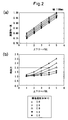
- FIG. 2 is a diagram showing changes in solidification uniformity and binding force when the up / down taper ratio and the casting speed are changed in a slab width of 1100 mm.
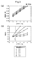
- FIG. 3 is a diagram showing changes in solidification uniformity and binding force when the up / down taper ratio and the casting speed are changed in a slab width of 2200 mm.
- FIG. 2 is a diagram showing changes in solidification uniformity and binding force when the up / down taper ratio and the casting speed are changed in a slab width of 1100 mm.
- FIG. 3 is a diagram showing changes in solidification uniformity and binding force when the up / down taper ratio and the casting speed are changed in a slab width of
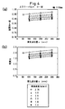
- FIG. 4 is a diagram showing changes in solidification uniformity and restraining force when the change point position x and the casting speed are changed in a slab width of 1100 mm.
- FIG. 5 is a diagram showing changes in solidification uniformity and restraining force when the change point position x and the casting speed are changed in a slab width of 2200 mm.
- FIG. 6 is a diagram showing changes in solidification uniformity and binding force when the total taper rate is changed.
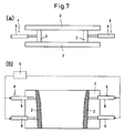
- FIG. 7 is a view showing a continuous casting mold of the present invention, in which (a) is a plan view and (b) is a sectional front view.
- FIG. 8 is a diagram showing a solidified shell shape at the lower end of the mold obtained by calculation.
- the present invention reduces the taper change point position from the meniscus as the maximum casting speed becomes faster, and thus in a wide casting width range from narrow to wide. Both the solidification uniformity and the restraining force can be maintained in a favorable range.
- the maximum casting speed for casting is V M (m / min), and the distance from the meniscus position of the multistage tapered short side mold plate to the first taper changing point in the casting direction is the changing point position x (mm). .
- the total taper rate T T , the upper taper rate T U , the lower taper rate T L , and the vertical taper ratio are defined as follows.
- W in the lower tapered face 6 L of the casting direction lowermost multistage tapered short side mold plate optionally define the upper and lower positions, the distance between both short sides, W 3 in the upper position (m), in the lower position 4 (m), when the distance from the upper position to the lower position is set to ⁇ L (m) (FIGS.
- JP 2006-346735 A and JP 2006-34636 A describe a method of estimating the solidification behavior of a slab in a mold by calculation. When the slope of the casting or the casting speed is set to an arbitrary value, the thickness of the solidified shell at each part around the four sides of the mold is calculated as shown in FIG.
- the ratio B / A between the maximum value A and the minimum value B of the solidified shell thickness at the lower end of the mold, the binding force between the solidified shell and the mold, and the gap amount can be obtained.
- the shape of the solidified shell at the lower end of the mold and the binding force between the solidified shell and the mold were determined for continuous casting using a multistage tapered short side mold plate.
- the shape of the solidified shell at the lower end of the mold is derived as shown in FIG. 8 by calculation.
- a portion with a thin solidified shell thickness may be formed on the long side of the solidified shell in the vicinity of the slab corner, and the solidified shell thickness at this portion can be set to the minimum value B of the shell thickness.
- the ratio B / A between the maximum value A and the minimum value B of the solidified shell thickness is referred to herein as “solidification uniformity”.
- solidification uniformity The ratio B / A between the maximum value A and the minimum value B of the solidified shell thickness.
- the calculation method of the present invention solidification uniformity and binding force.
- the distance L from the meniscus position to the lower end of the mold is about 900 mm
- the change point position x is about 300 mm.
- the casting width is 1100 mm (narrow), the total taper rate is 1.6% / m, the changing point position x of the two-step taper short side mold plate is constant 300 mm, and the casting speed is 1.0 to 3.0 m / min.
- the bending condition of the short side mold plate was changed by changing the vertical taper ratio of the two-step taper short side mold plate, and the solidification uniformity and the binding force were calculated by the calculation method of the present invention. As shown in FIG. 2, if the taper ratio is the same, the solidification uniformity improves as the casting speed increases, but the binding force also increases.
- the upper and lower taper ratio preferable range is 5.0 or less and the casting speed is 2 at a casting speed of 2.0 m / min.
- the preferable range of the upper and lower taper ratio was 4.0 or less at 0.5 m / min, and the preferable range of the upper and lower taper ratio was 3.0 or less at the casting speed of 3.0 m / min.
- the shape of a short side mold plate having a casting width of 1100 mm and good solidification uniformity and restraining force (a mold shape having an up / down taper ratio of 3.0 optimized for a casting speed in the range of 3.0 m / min)
- the casting width was as wide as 2200 mm.
- the total taper ratio was kept at 1.6% / m.
- the width was 2200 mm and the up / down taper ratio was 1.7.
- the casting speed was 3.0 m / in when the slab width was widened while keeping the total taper constant.
- the preferred range of the vertical taper ratio was reduced to less than 1.7 and the solidification uniformity was also reduced (FIG. 3). That is, it was found that in a mold optimized for high-speed casting up to a casting speed of 3.0 m / min at a width of 1100 mm, if the casting width was 2200 mm, it was out of the optimum range. Therefore, when the multi-step taper is optimized for each casting speed in the width of 1100 mm, the change is not made by fixing the change point position x and changing the vertical taper ratio but by keeping the vertical taper ratio constant at 4.0. I tried changing the point position x.
- the total taper rate was 1.6% / m
- the change point position x was changed, and the solidification uniformity and the binding force were calculated by the calculation method of the present invention.
- the result is shown in FIG.
- the change point position preferred range was 300 mm or less
- the change point position preferred range was 200 mm or less.
- the vertical taper ratio was 2.5 at the cast width of 2200 mm. Therefore, in the 2200 mm width, the total taper rate is set to 1.6% / m, and the vertical taper ratio is kept constant at 2.5 as described above, and the change point position x is changed by the calculation method of the present invention.
- the calculation result of solidification uniformity and binding force is shown (FIG. 5). As is apparent from FIG. 5, it was found that if the change point position x is 200 mm or less, a good range can be secured at a casting speed of 3.0 m / min or less even if the casting width is 2200 mm.
- the change point position x when comparing the upper and lower taper ratio at the time of narrow width with a suitable upper limit taper ratio when applied at the time of wide width using a mold optimized by changing the vertical ratio for each casting speed, the change point position x
- a mold optimized by changing the width it is possible to increase the preferred vertical taper ratio, and when the change point x is changed, the width is wider than the narrow width.
- the coagulation uniformity increased conversely although the preferred vertical taper ratio decreased. That is, when determining the optimum taper shape of the multi-stage tapered short side mold plate when the casting speed becomes high, as shown in FIGS. 4 and 5, the change point position x is raised upward as the casting speed becomes higher.
- V M is a solution eliminates exceeds 3.75 m / min. That is, the upper limit of V M in the present invention is 3.75 m / min.
- the upper limit of x is set to 300 mm because when the upper and lower taper ratio is to be secured above a certain value, when the upper strong taper region becomes longer, the taper rate of the lower taper portion becomes smaller and the total taper rate is constant and the width is increased. This is because when the width is reduced and the casting is narrow, the lower taper ratio becomes extremely small, and it tends to become a reverse taper (expands as the taper goes down), which easily causes trouble that the slab bulges at the bottom of the mold. .
- the effect is remarkable as the maximum casting speed V M is increased. Maximum casting speed V M can exhibit particularly remarkable effects in the high-speed casting of 2.5 m / min greater.
- the casting speed is fixed at 1.5 m / min
- the casting width is fixed at 1100 mm
- the total taper ratio is changed to solidify.
- Uniformity and binding force were calculated.
- the slab thickness was 240 mm. The results are shown in FIG. As is clear from the figure, the solidification uniformity can be maintained well if the total taper rate is 0.5% / m or more. Further, if the total taper rate is 2.0% / m or less, the restraining force is small, and it can be held well.
- the multi-stage tapered short side mold plate used in the present invention a mold plate having a taper of three or more stages may be used, but as a result of setting the change point position upward, the two-stage tapered short side mold plate is sufficient.
- the cast slab thickness is preferably 220 mm to 300 mm, more preferably 240 mm to 300 mm.
- the slab thickness exceeds 300 mm, excessive equipment is required as a continuous casting mold for changing the width during casting, which is substantially difficult to realize. If the casting thickness is less than 240 mm, the diameter of the immersion nozzle for injecting the molten metal from the tundish must be reduced, so that uniform injection of the molten metal becomes difficult.
- the continuous casting mold 1 of the present invention includes a long-side mold plate 3 and a multistage tapered short-side mold plate 2 having two or more short-side taper ratios (unit:% / m) different in the casting direction.
- the long-side mold plate 3 and the short-side mold plate 2 are each composed of a pair, and the side facing the solidified shell is preferably a water-cooled copper plate, and the opposite surface is a steel back frame.
- the width of the short side mold plate 2 is substantially equal to the thickness of the cast piece to be cast.
- the continuous casting mold 1 of the present invention further includes a short side driving device 4 that can change the width of the cast slab and the inclination of the short side, and a control device 5 for the short side driving device.
- the taper ratio at the uppermost short side in the casting direction is the upper taper ratio
- the taper ratio at the lowermost side is the lower taper ratio
- the taper ratio at the short side surface connecting the meniscus part and the lower end of the mold with a straight line is the total taper ratio.
- the value obtained by dividing the upper taper rate by the lower taper rate is defined as the upper and lower taper ratio, which is the same as in the continuous casting method of the present invention.
- the control device 5 of the short side drive device drives the short side mold plate so that the same total taper ratio is obtained in any slab width during casting, and the vertical taper ratio is 4 or less in any slab width. Control is preferable as a practical operation mode.
- the short-side drive device 4 has, for example, two upper and lower drive actuators 9 and holds the short-side mold plate 2 by the actuator 9 from the back frame side. By determining the position of the short-side mold plate by the movement of the upper and lower actuators 9, the total taper ratio of the short-side mold plate 2 can be set to a predetermined value for each casting width.
- an electric cylinder, a hydraulic cylinder, or the like can be used. Or it is good also as an apparatus which has a drive means which performs a reciprocating motion and a swing motion of a short side mold plate as a short side drive device.
- the continuous casting mold of the present invention is preferable because the minimum castable slab width is 1100 mm or less and the maximum castable slab width is 2200 mm or more, because a slab having a wide range can be cast. .
- the minimum castable slab width is preferably 800 mm or less.
- the minimum castable slab width is practically 600 mm.
- the maximum castable slab width is realistic 2500 mm.
- the solidification level is reduced in a wide casting width range from narrow to wide by shortening the taper change point position from the meniscus as the maximum casting speed increases. It is possible to maintain the binding force in a good range once.
Landscapes
- Engineering & Computer Science (AREA)
- Mechanical Engineering (AREA)
- Continuous Casting (AREA)
Abstract
Description
鋳型内で凝固シェルの凝固が進行しつつ、その凝固シェルを下方に移動する過程において、凝固シェルは凝固が進行するとともに凝固収縮する。従って、鋳型内溶融金属のメニスカス位置で凝固を開始した凝固シェルは、鋳型の下端に到達したときには収縮しており、凝固中鋳片の幅や厚さがメニスカス位置に比較して小さくなっている。スラブ連続鋳造においては鋳片の厚さに比較して幅が広いので、鋳片幅方向の凝固収縮量が大きい。凝固シェルの凝固収縮に伴って鋳型の下方において鋳型と凝固シェルとの間に空隙が生じると、凝固シェルから鋳型への抜熱が阻害され、十分な鋳型冷却ができなくなるとともに、鋳型による支持を失った凝固シェルが外方に膨れるバルジングを起こすこととなる。
そこで、少なくとも鋳型短辺にテーパを設けることが行われている。テーパを設けるとは、対向する両短辺間の間隔について、鋳型上方のメニスカス位置における間隔に対し、鋳型下端の間隔を狭めることを意味する。
本発明において、図1(c)に示すように、鋳造方向任意の位置に上方位置と下方位置を定め、両短辺間の距離を、上方位置においてW1、下方位置においてW2、上方位置から下方位置までの距離をΔLとおいたとき、テーパ量(%)、テーパ率(%/m)を
テーパ量(%)={(W1−W2)/ΔL}×100 (3)
テーパ率(%/m)={(W1−W2)/W0/ΔL}×100
(4)
と定義し、このように呼ぶこととする。ここでW0は、ある幅に応じて、決まった長さなら、どこでも良い。鋳型上端幅、鋳型下端幅等とすることができる。ここではW0(m)をメニスカス幅(WM)とした。
短辺テーパ量が小さすぎる場合には、凝固シェルと短辺鋳型板との接触が不均一になり、冷却のアンバランスが発生し、凝固シェル成長の不均一、溶融金属静圧による鋳片表面の割れが発生する。特に、短辺テーパ量が適正量よりも小さい場合、鋳型下端付近における凝固シェルの厚み分布において、図8に示すように、長辺側凝固シェルのコーナー近傍に凝固厚みが特に薄い部位が発生しやすくなり、この部位に対応する鋳片表面に縦割れが発生しやすい。また短辺テーパ量が大きすぎる場合には、凝固シェルと短辺鋳型板との接触が強くなり、凝固シェルに過大な応力が加わり、凝固シェルの破断、およびシェル破断に伴うブレークアウトが発生する。あるいは凝固シェルと鋳型の摩擦力増大に伴う鋳型寿命低下を引き起こす場合がある。
適正な短辺テーパについて、例えば特開2005−211936号公報においては、短辺テーパ率βnを0.7~1.3%/mとして操業することが行われているとしている。 従来の短辺鋳型板2の凝固シェルに面する面(以下「テーパ面6」ともいう。)は、図1(c)に示すように、上部から下部へ向かって平面で加工されている。しかし、凝固シェルの凝固収縮速度は、鋳型内の鋳造方向の各位置において一定ではなく、メニスカス近傍では凝固収縮速度が速く、鋳型下端に近づくにつれ凝固収縮速度が遅くなる。従って、短辺鋳型板と接する凝固シェルの面は平面ではなく、鋳型の下方に行くに従ってシェルのテーパ量が小さくなる曲面を形成していると考えられる。
特開平2−247059号公報においては、鋳型短辺のテーパを湾曲面として制御するテーパ制御方法が開示されている。短辺鋳型を背面の少なくとも3地点で支持し、変形を加える。3点のうち少なくとも1箇所、例えば中央部に加圧装置を取り付け、短辺銅板表面と自由収縮プロフィールとを予めおよび操業中も一致させることにより一層均一な抜熱が可能になるとしている。中心荷重点に2~5トンの力を加えることにより、最大撓み量は0.33~0.83mmにまでなり、これは溶鋼の凝固収縮量から考えれば十分な量であるとしている。
特開昭56−53849号公報においては、最適な短辺テーパを理論解析により求めており、最適短辺テーパはメニスカスからの鋳込み方向に沿う距離Z及び鋳造速度Vに依存し、各距離Zにおける最適テーパ率(%/m)がZ−1/2に比例するとともに、(4−V)(m/min)に比例するとしている。同公報の実施例1及び第2図によると、断面寸法20.8cm×105cmの鋳型の短辺を3段階のテーパを有する形状とし、テーパ率が上から2%/m、0.7%/m、0.4%/mとなっている。また実施例2及び第3図によると、断面寸法22cm×124cmの鋳型の短辺を3段階のテーパを有する形状とし、テーパ率が上から4%/m、1.3%/m、0.8%/mとなっている。このように、鋳造方向に2段階、あるいは3段階以上のテーパを有する鋳型を多段テーパ鋳型と呼び、このようなテーパを有する短辺鋳型板を多段テーパ短辺鋳型板と呼ぶことにする。
連続鋳造においては、鋳造速度が速いほど、生産性を向上することができる。スラブの連続鋳造においても、鋳造速度が2.0m/min前後から、最近は3.0m/min程度まで鋳造速度が上昇している。多段テーパ短辺鋳型板を用いた連続鋳造において、鋳造速度が速くなるに従って多段テーパ短辺鋳型板の最適形状が変化し、また多段テーパ短辺鋳型板を用いた鋳造方法も変化する。例えば、特開平3−210953号公報によれば、鋳造速度が速くなると、多段テーパ短辺鋳型板の湾曲の程度を緩めるとともに全体の傾斜を小さくするとしている。
しかし、一方で、スラブの連続鋳造においては、鋳造する鋳片が向け先ごとに種々の幅を有するので、連続鋳造を続けながら鋳造する鋳片幅を変更することが行われる。図7に示すように、短辺鋳型板2を長辺方向に移動するための短辺駆動装置4を有し、短辺鋳型板2を長辺鋳型板3で挟み込んだままで短辺鋳型板2の位置を変更することにより、鋳造中に鋳片幅を変更することができる。即ち、長辺鋳型板3と短辺鋳型板2をいずれも交換することなく、種々の幅を有する鋳片を同一の連続鋳造鋳型1を用いて鋳造することが可能である。
更に、特開2006−346735号公報及び特開2006−346736号公報には、鋳型内での鋳片の凝固挙動を計算により推定する方法が記載されており、鋳型の鋳造方向の傾き、あるいは鋳造速度を任意の値に設定した際に、鋳型四周各部位における凝固シェルの厚さが算出され、この結果に基づき、鋳型下端における凝固シェル厚の最大値と最小値の比、凝固シェルと鋳型間の拘束力、ギャップ量を求めることができるとされている。
スラブ連続鋳造においては、同一の短辺鋳型板を用い、鋳型における短辺鋳型板の位置を変更することにより、種々の鋳造幅に対応して鋳造を行うことができる。上述の高速鋳造速度に対応して短辺面の湾曲度が小さい短辺鋳型板を用いて種々の鋳造幅の鋳片を鋳造したところ、狭幅及び中間幅では良好な連続鋳造が可能であったものの、広幅の鋳造に際して多段テーパ短辺鋳型板を用いた効果を十分に発揮できない場合があることがわかった。
本発明は、多段テーパ短辺鋳型板を用いた連続鋳造において、最高鋳造速度が高速であっても、狭幅から広幅までいずれの鋳造幅においても多段テーパ短辺鋳型板の効果を発揮することのできる連続鋳造方法、多段テーパ短辺鋳型板、連続鋳造装置を提供することを目的とする。即ち、本発明の要旨は以下のとおりである。
(1)鋳造方向に異なった2以上のテーパを有する多段テーパ短辺鋳型板を用いる連続鋳造方法であって、鋳造する最高鋳造速度をVM(m/min)とし、メニスカス位置から鋳造方向に最初のテーパ変化点までの距離を変化点位置x(mm)とし、xをVMの関数として下記(1)式、(2)式の範囲内とすることを特徴とする連続鋳造方法。
50≦x≦300:VM≦2.5 ・・・(1)式
50≦x≦300−200(VM−2.5):2.5<VM≦3.75・・・(2)式
(2)さらに複数の鋳片幅の鋳片を鋳造することを特徴とする上記(1)に記載の連続鋳造方法。
(3)短辺鋳型板が、2段テーパ短辺鋳型板であることを特徴とする上記(1)又は(2)に記載の連続鋳造方法。
(4)鋳造する最高鋳造速度がVM(m/min)である連続鋳造用に用い、鋳造方向に異なった2以上のテーパを有する多段テーパ短辺鋳型板であって、メニスカス位置から鋳造方向に最初のテーパ変化点までの距離を変化点位置x(mm)とし、xをVMの関数として下記(1)式、(2)式の範囲内とすることを特徴とする連続鋳造用の短辺鋳型板。
50≦x≦300 :VM≦2.5 ・・・(1)式
50≦x≦300−200(VM−2.5):2.5<VM≦3.75・・・(2)式
(5)2段テーパ短辺鋳型板であることを特徴とする上記(4)に記載の連続鋳造用の短辺鋳型板。
(6)長辺鋳型板3と、鋳造方向に異なった2以上のテーパを有する多段テーパ短辺鋳型板2とを有し、鋳造する最高鋳造速度がVM(m/min)であり、多段テーパ短辺鋳型板2のメニスカス位置から鋳造方向に最初のテーパ変化点までの距離を変化点位置x(mm)とし、xをVMの関数として下記(1)式、(2)式の範囲内とすることを特徴とする連続鋳造鋳型。
50≦x≦300 :VM≦2.5 ・・・(1)式
50≦x≦300−200(VM−2.5) :2.5<VM≦3.75・・・(2)式
(7)短辺鋳型板2が、2段テーパ短辺鋳型板であることを特徴とする上記(6)に記載の連続鋳造鋳型。
図2は、鋳片幅1100mmにおいて、上下テーパ比と鋳造速度を変更したときの凝固均一度、拘束力の変化を示す図である。
図3は、鋳片幅2200mmにおいて、上下テーパ比と鋳造速度を変更したときの凝固均一度、拘束力の変化を示す図である。
図4は、鋳片幅1100mmにおいて、変化点位置xと鋳造速度を変更したときの凝固均一度、拘束力の変化を示す図である。
図5は、鋳片幅2200mmにおいて、変化点位置xと鋳造速度を変更したときの凝固均一度、拘束力の変化を示す図である。
図6は、トータルテーパ率を変更したときの凝固均一度、拘束力の変化を示す図である。
図7は、本発明の連続鋳造鋳型を示す図であり、(a)は平面図、(b)は断面正面図である。
図8は、計算で求めた鋳型下端における凝固シェル形状を示す図である。
発明の効果
本発明は、多段テーパ短辺鋳型板を用いた連続鋳造において、最高鋳造速度が速くなるほどメニスカスからのテーパ変化点位置を短くすることにより、狭幅から広幅までの広い鋳造幅範囲において、凝固均一度と拘束力をともに良好な範囲に維持することが可能となる。
本発明は、またトータルテーパ率TT、上テーパ率TU、下テーパ率TL、上下テーパ比を以下のように定義する。
両短辺間の距離を、メニスカス位置においてWM(m)、鋳型下端においてWB(m)、メニスカス位置から鋳型下端までの距離をL(m)とおいたとき(図1(a)(b))、トータルテーパ率TT(%/m)を
TT(%/m)={(WM−WB)/WM/L}×100
・・・(5)式
と定義する。
多段テーパ短辺鋳型板の鋳造方向最上部の上テーパ面6Uにおいて、上方位置と下方位置を任意に定め、両短辺間の距離を、上方位置においてW1(m)、下方位置においてW2(m)、上方位置から下方位置までの距離をΔL(m)とおいたとき(図1(a)(b))、上テーパ率TU(%/m)を
TU(%/m)={(W1−W2)/WM/ΔL}×100
・・・(6)式
と定義する。
多段テーパ短辺鋳型板の鋳造方向最下部の下テーパ面6Lにおいて、上方位置と下方位置を任意に定め、両短辺間の距離を、上方位置においてW3(m)、下方位置においてW4(m)、上方位置から下方位置までの距離をΔL(m)とおいたとき(図1(a)(b))、下テーパ率TL(%/m)を
TL(%/m)={(W3−W4)/WM/ΔL}×100
・・・(7)式
と定義する。
上下テーパ比は、
上下テーパ比=上テーパ率/下テーパ率=TU/TL
・・・(8)式
と定義する。
特開2006−346735号公報及び特開2006−346736号公報には、鋳型内での鋳片の凝固挙動を計算により推定する方法が記載されていることは前述した通りであり、鋳型の鋳造方向の傾き、あるいは鋳造速度を任意の値に設定した際に、鋳型四周各部位における凝固シェルの厚さが図8のように算出される。この結果に基づき、鋳型下端における凝固シェル厚の最大値Aと最小値Bの比B/A、凝固シェルと鋳型間の拘束力、ギャップ量を求めることができる。そして、これらの特許公報に記載の計算方法を用い、多段テーパ短辺鋳型板を使用する連続鋳造について、鋳型下端における凝固シェルの形状、凝固シェルと鋳型間の拘束力を求めた。鋳型下端における凝固シェルの形状は、計算によって図8のように導出される。鋳片コーナー近傍における凝固シェルの長辺側に、凝固シェル厚が薄い部位が形成されることがあり、この部位の凝固シェル厚をシェル厚の最小値Bと置くことができる。そして、凝固シェル厚の最大値Aと最小値Bの比B/Aを、ここでは「凝固均一度」と呼ぶ。凝固均一度が良好な鋳造を行った場合には、コーナー近傍の長辺側におけるシェル厚の薄い部位のシェル厚みが、その他の厚い部位のシェル厚に近づくこととなる。
実際に溶鋼の連続鋳造を行い、鋳造中に鋳型内溶鋼にSを添加し、凝固後鋳片のサルファープリントによって鋳型下端位置での凝固シェルの厚み分布を評価したところ、上記計算で求めた凝固均一度と、サルファープリントから求めた鋳型下端凝固シェル厚みの最大と最小の比とが、よく一致することがわかった。従って、計算で求めた凝固均一度を指標として、好適な連続鋳造方法を見出すことが可能である。
計算で求めた凝固均一度(B/A)の値が0.7以上であれば、実鋳造においても良好な凝固均一度を確保することができる。計算で求めた拘束力(各幅での基準値(1段テーパでテーパ率1.0%/mの場合の拘束力で正規化した値)が2.0以下であれば、実鋳造においても拘束の少ない良好な鋳造を行うことができる。また、凝固均一度(B/A)及び拘束力を上記好ましい範囲とすることにより、連続鋳造を行ったときにブレークアウトが起こらないことを、実際の連続鋳造の結果によって確認している。
次に、上記2件の特許(特開2006−346735号公報及び特開2006−346736号公報)に基づく計算方法(以下「本発明の計算方法」ともいう。)により、凝固均一度と拘束力を計算し、多段テーパ短辺鋳型板の最適な形状を検討することとする。
従来の多段テーパ短辺鋳型板、特に2段テーパ短辺鋳型板において、メニスカス位置から鋳型下端までの距離Lは概ね900mm程度であり、変化点位置xは300mm程度であった。そして、最高鋳造速度VMが2.5m/min程度までの鋳造速度を採用する場合、上下テーパ比として4.0程度のテーパを採用し、凝固均一度及び拘束力の両方とも良好な鋳造を実現することができた。この点については、上記本発明の計算方法によって確認することができる。
鋳造幅を1100mm(狭幅)、トータルテーパ率を1.6%/m、2段テーパ短辺鋳型板の変化点位置xを300mm一定とし、鋳造速度を1.0~3.0m/minで変化させ、2段テーパ短辺鋳型板の上下テーパ比を変化させることによって短辺鋳型板の湾曲状況を変化させ、本発明の計算方法によって凝固均一度と拘束力を計算した。
図2に示すように、同じ上下テーパ比であれば鋳造速度が速くなるに従って凝固均一度が改善するものの拘束力も増大する。凝固均一度と拘束力をともに良好範囲に保つためには、鋳造速度が速くなるに従って、上下テーパ比を低くすると好ましいことがわかる。凝固均一度と拘束力をともに良好に保持できる上下テーパ比範囲を鋳造速度ごとに調べてみると、鋳造速度が2.0m/minでは上下テーパ比好適範囲が5.0以下、鋳造速度が2.5m/minでは上下テーパ比好適範囲が4.0以下、鋳造速度が3.0m/minでは上下テーパ比好適範囲が3.0以下という結果となった。
次に、鋳造幅1100mmで凝固均一度と拘束力が良好であった短辺鋳型板形状(鋳造速度が3.0m/minの範囲までで最適化した上下テーパ比3.0の鋳型形状)を用い、鋳造幅を2200mmと広幅にした。幅を変更するに際し、トータルテーパ率を1.6%/mのまま保持したところ、幅2200mmで上下テーパ比は1.7となった。
鋳造幅2200mm(広幅)について本発明の計算方法によって凝固均一度と拘束力を計算したところ、トータルテーパ率を一定で保持したまま、鋳片幅を広げた場合は、鋳造速度が3.0m/minでは上下テーパ比好適範囲が低下して、1.7未満となり、凝固均一度も低下することがわかった(図3)。即ち、幅1100mmにおいて鋳造速度3.0m/minまでの高速鋳造について最適化した鋳型において、鋳造幅を2200mmの広幅とすると、最適範囲から外れることがわかった。
そこで、1100mm幅において鋳造速度ごとに多段テーパの最適化を図るに際し、変化点位置xを固定して上下テーパ比を変化させるのではなく、上下テーパ比を4.0一定に保持した上で変化点位置xを変更してみた。トータルテーパ率を1.6%/mとし、変化点位置xを変化させて本発明の計算方法で凝固均一度と拘束力を計算した。その結果を図4に示す。鋳造速度が2.5m/min以下では変化点位置好適範囲が300mm以下、鋳造速度が3.0m/minでは変化点位置好適範囲が200mm以下となった。
次に、幅1100mmで好適であった変化点位置xを有する短辺鋳型板(鋳造速度が3.0m/minの範囲までで最適化した変化点位置が200mmの鋳型形状)を用い、幅2200mmの鋳造での計算を行った。トータルテーパ率は1.6%/mで保持し、トータルテーパ率一定で鋳片幅を広げた場合、鋳造幅2200mmにおいて上下テーパ比は2.5になった。そこで、2200mm幅において、トータルテーパ率を1.6%/mとし、前記と同様に上下テーパ比を2.5一定に保持した上で、変化点位置xを変化させて本発明の計算方法で凝固均一度と拘束力を計算した結果を示す(図5)。図5から明らかなように、変化点位置xが200mm以下であれば、鋳造幅2200mmであっても、鋳造速度3.0m/min以下において良好範囲を確保できることがわかった。従って、最高鋳造速度が3.0m/minの鋳造を行うとき、変位点位置が200mm以下であれば良好に連続鋳造を行うことができる。
同様に、鋳造速度3.75m/minにおいては、変化点位置xが50mm以下であれば、幅1200mm(図4)、幅2200mm(図5)のいずれにおいても、良好な鋳造を行うことができる。従って、最高鋳造速度が3.75m/minの鋳造を行うとき、変位点位置が50mm以下であれば、良好に連続鋳造を行うことができる。
以上述べたように、狭幅時の上下テーパ比を鋳造速度ごとに上下比率を変化させて最適化した鋳型を用いて広幅時に適用した場合の好適な上限テーパ比率と比較すると、変化点位置xを変化させて最適化した鋳型を用いて広幅時に適用した場合の方が、好適な上下テーパ比を上げることができ、また変化点位置xを変化させると、狭幅時よりも広幅時の方が好適な上下テーパ比が低下するものの、凝固均一度は逆に上昇することがわかった。即ち、鋳造速度が高速になったときに多段テーパ短辺鋳型板の最適テーパ形状を決定するに際し、図4および図5に示すように、鋳造速度が速くなるほど変化点位置xを上方に上げることにより、上下テーパ比を変化させる場合よりも、鋳造幅が広幅のときにも良好な凝固均一度と拘束力を維持することが可能であることがわかった。
因みに、図4および図5の関係は、工業的な観点で想定される鋳片幅である600mm~2500mmの範囲で、同様の関係を示すことも、計算および実機試験により、確認している。
図4および図5の関係から、前記の凝固均一度が0.7以上、拘束力が2.0以下とする好適範囲になる条件を最高鋳造速度VMの変数として式に表すと、下記(1)式、(2)式のように導出される。
50≦x≦300 :VM≦2.5 ・・・(1)
50≦x≦300−200(VM−2.5) :2.5<VM≦3.75・・・(2)式
xの下限を50mmとしているのは、これ以上変化点位置が鋳型の上方にあると、多段テーパの効果が十分得られず、通常の1段テーパとほとんどかわらなくなるからである。上記(2)式から、VMが3.75m/minを超えると解がなくなる。即ち、本発明においてVMの上限は3.75m/minである。また、xの上限を300mmとしているのは、上下テーパ比率をある一定値以上確保しようとした場合に、上部強テーパ領域が長くなると下部テーパ部のテーパ率が小さくなり、トータルテーパ率一定で幅変更して狭幅鋳造した場合に、下テーパ率が極端に小さくなり逆テーパ(テーパが下にいくほど広がる)になりやすく、鋳型下部で鋳片がバルジングするトラブルが発生しやすくなるためである。
本発明においては、最高鋳造速度VMが高くなるほどその効果が顕著である。最高鋳造速度VMが2.5m/min超の高速鋳造において特に顕著な効果を発揮することができる。
次に、上記と同じ2段テーパ短辺鋳型板(変化点位置が200mmの鋳型)を用い、鋳造速度を1.5m/min、鋳造幅を1100mmで固定し、トータルテーパ率を変化させて凝固均一度と拘束力を計算で求めた。鋳片厚みは240mmとした。結果を図6に示す。図から明らかなように、トータルテーパ率を0.5%/m以上とすれば凝固均一度を良好に保持することができる。またトータルテーパ率を2.0%/m以下とすれば拘束力が小さく、良好に保持することができる。
本発明で用いる多段テーパ短辺鋳型板としては、3段以上のテーパを有する鋳型板を用いてもよいが、変化点位置を上方に設定した結果として、2段テーパ短辺鋳型板で十分にその効果を発揮することができる。
本発明において、鋳造する鋳片厚みは、好ましくは220mm~300mm、より好ましくは240mm~300mmである。鋳片厚みが300mmを超える場合は、鋳造中に幅を変更する連続鋳造鋳型としては過大な設備を必要とし、実質的に実現困難である。また、鋳造厚みが240mm未満であると、タンディッシュから溶融金属を注入するための浸漬ノズルの直径を小さくしなければならなくなるので、均一な溶融金属の注入が困難になる。鋳造厚みが220mm未満になるとより均一な注入が一層困難になる。
次に、図7に基づいて、本発明の鋳造方法を実現するための連続鋳造鋳型について説明する。
本発明の連続鋳造鋳型1は、長辺鋳型板3と、鋳造方向に異なった2以上の短辺テーパ率(単位:%/m)を有する多段テーパ短辺鋳型板2とを有する。長辺鋳型板3及び短辺鋳型板2は、それぞれ2枚で1組を構成し、凝固シェルに面する側が水冷銅板、その反対面を鋼製のバックフレームとすると良い。短辺鋳型板2の幅が鋳造する鋳片の厚みにほぼ等しい。短辺鋳型板2を2枚の長辺鋳型板3で挟み込むことにより、矩形の鋳造空間を有する鋳型が形成される。
この連続鋳造鋳型で鋳造する最高鋳造速度がVM(m/min)であるとき、多段テーパ短辺鋳型板2のメニスカス位置から鋳造方向に最初のテーパ変化点までの距離を変化点位置x(mm)とし、xをVMの関数として下記(1)式、(2)式の範囲内とする。これにより、狭幅から広幅までの広い鋳造幅範囲において、凝固均一度と拘束力をともに良好な範囲に維持することが可能となる。
50≦x≦300 :VM≦2.5 ・・・(1)式
50≦x≦300−200(VM−2.5) :2.5<VM≦3.75・・・(2)式
本発明の連続鋳造鋳型1はさらに、鋳造する鋳片幅及び短辺の傾きを変更することのできる短辺駆動装置4と、短辺駆動装置の制御装置5とを有する。鋳造方向最上位の短辺テーパ率を上テーパ率、最下位の短辺テーパ率を下テーパ率、短辺表面のメニスカス部と鋳型下端部を直線で結んだ短辺テーパ率をトータルテーパ率とし、上テーパ率を下テーパ率で除した値を上下テーパ比と定義する点は、上記本発明の連続鋳造方法と同様である。
短辺駆動装置の制御装置5は、鋳造中いずれの鋳片幅においても同一のトータルテーパ率とし、いずれの鋳片幅においても上下テーパ比は、4以下とするように短辺鋳型板を駆動制御することが現実的な操業形態として、好ましい。
短辺駆動装置4は、例えば上下2段の駆動アクチュエータ9を有し、短辺鋳型板2をバックフレーム側からアクチュエータ9によって保持する。上下のアクチュエータ9それぞれの運動によって短辺鋳型板の位置を定めることにより、各鋳造幅毎に、短辺鋳型板2のトータルテーパ率を所定の値に定めることができる。アクチュエータ9としては、電動シリンダ、油圧シリンダなどを用いることができる。あるいは、短辺駆動装置として短辺鋳型板の往復運動と首振り運動を行う駆動手段を有する装置としても良い。
なお、連続鋳造中に鋳造幅を変更するに際しては、正常な鋳造を行いつつ鋳造幅を連続的に変更することが要請される。このような幅変更を実施している最中には、トータルテーパ率を変更して円滑な幅変更を実施することが必要となり、トータルテーパ率を一定に保持することはできない。
本発明の連続鋳造鋳型は、鋳造可能最小鋳片幅が1100mmあるいはそれ以下、鋳造可能最大鋳片幅が2200mmあるいはそれ以上であれば、広範囲の幅を有する鋳片を鋳造することができるので好ましい。鋳造可能最小鋳片幅が800mmあるいはそれ以下であると好ましい。鋳造可能最小鋳片幅は600mmが現実的である。鋳造可能最大鋳片幅は2500mmが現実的である。
Claims (7)
- 鋳造方向に異なった2以上のテーパを有する多段テーパ短辺鋳型板を用いる連続鋳造方法であって、鋳造する最高鋳造速度をVM(m/min)とし、メニスカス位置から鋳造方向に最初のテーパ変化点までの距離を変化点位置x(mm)とし、xをVMの関数として下記(1)式、(2)式の範囲内とすることを特徴とする連続鋳造方法。
50≦x≦300 :VM≦2.5・・・(1)式
50≦x≦300−200(VM−2.5) :2.5<VM≦3.75・・・(2)式 - さらに複数の鋳片幅の鋳片を鋳造することを特徴とする請求項1に記載の連続鋳造方法。
- 短辺鋳型板が、2段テーパ短辺鋳型板であることを特徴とする請求項1又は2に記載の連続鋳造方法。
- 鋳造する最高鋳造速度がVM(m/min)である連続鋳造用に用い、鋳造方向に異なった2以上のテーパを有する多段テーパ短辺鋳型板であって、メニスカス位置から鋳造方向に最初のテーパ変化点までの距離を変化点位置x(mm)とし、xをVMの関数として下記(1)式、(2)式の範囲内とすることを特徴とする連続鋳造用の短辺鋳型板。
50≦x≦300 :VM≦2.5・・・(1)式
50≦x≦300−200(VM−2.5) :2.5<VM≦3.75・・・(2)式 - 2段テーパ短辺鋳型板であることを特徴とする請求項4に記載の連続鋳造用の短辺鋳型板。
- 長辺鋳型板と、鋳造方向に異なった2以上のテーパを有する多段テーパ短辺鋳型板とを有し、鋳造する最高鋳造速度がVM(m/min)であり、前記多段テーパ短辺鋳型板のメニスカス位置から鋳造方向に最初のテーパ変化点までの距離を変化点位置x(mm)とし、xをVMの関数として下記(1)(2)式の範囲内とすることを特徴とする連続鋳造鋳型。
50≦x≦300 :VM≦2.5・・・(1)式
50≦x≦300−200(VM−2.5) :2.5<VM≦3.75・・・(2)式 - 短辺鋳型板が、2段テーパ短辺鋳型板であることを特徴とする請求項6に記載の連続鋳造鋳型。
Priority Applications (4)
| Application Number | Priority Date | Filing Date | Title |
|---|---|---|---|
| CN200980158156.XA CN102355964B (zh) | 2009-03-19 | 2009-03-19 | 连铸方法、连铸用的短边铸模板和连铸铸模 |
| PCT/JP2009/056215 WO2010106696A1 (ja) | 2009-03-19 | 2009-03-19 | 連続鋳造方法及び連続鋳造鋳型 |
| BRPI0924937-0A BRPI0924937B1 (pt) | 2009-03-19 | 2009-03-19 | Method of continuous casting, laterally narrow molding plate, and mold for continuous casting |
| KR1020117019262A KR20110103474A (ko) | 2009-03-19 | 2009-03-19 | 연속 주조 방법 및 연속 주조 주형 |
Applications Claiming Priority (1)
| Application Number | Priority Date | Filing Date | Title |
|---|---|---|---|
| PCT/JP2009/056215 WO2010106696A1 (ja) | 2009-03-19 | 2009-03-19 | 連続鋳造方法及び連続鋳造鋳型 |
Publications (1)
| Publication Number | Publication Date |
|---|---|
| WO2010106696A1 true WO2010106696A1 (ja) | 2010-09-23 |
Family
ID=42739362
Family Applications (1)
| Application Number | Title | Priority Date | Filing Date |
|---|---|---|---|
| PCT/JP2009/056215 Ceased WO2010106696A1 (ja) | 2009-03-19 | 2009-03-19 | 連続鋳造方法及び連続鋳造鋳型 |
Country Status (4)
| Country | Link |
|---|---|
| KR (1) | KR20110103474A (ja) |
| CN (1) | CN102355964B (ja) |
| BR (1) | BRPI0924937B1 (ja) |
| WO (1) | WO2010106696A1 (ja) |
Cited By (1)
| Publication number | Priority date | Publication date | Assignee | Title |
|---|---|---|---|---|
| JP2013220443A (ja) * | 2012-04-17 | 2013-10-28 | Nippon Steel & Sumitomo Metal Corp | 連続鋳造用鋳型およびこれを用いた鋼の連続鋳造方法 |
Citations (1)
| Publication number | Priority date | Publication date | Assignee | Title |
|---|---|---|---|---|
| JP2007175769A (ja) * | 2005-11-30 | 2007-07-12 | Kobe Steel Ltd | 連続鋳造方法 |
Family Cites Families (8)
| Publication number | Priority date | Publication date | Assignee | Title |
|---|---|---|---|---|
| US4306610A (en) * | 1979-10-03 | 1981-12-22 | Korf Technologies, Inc. | Method of controlling continuous casting rate |
| ES2056670T5 (es) * | 1991-02-06 | 2001-02-01 | Concast Standard Ag | Lingotera para la colada continua de metales, particularmente de acero. |
| CN2250210Y (zh) * | 1996-01-24 | 1997-03-26 | 章仲禹 | 水平连铸高效耐磨结晶器铜套 |
| CN2288798Y (zh) * | 1996-10-25 | 1998-08-26 | 冶金工业部北京冶金设备研究院 | 管式连铸结晶器 |
| KR100376504B1 (ko) * | 1998-08-04 | 2004-12-14 | 주식회사 포스코 | 연속주조방법및이에이용되는연속주조장치 |
| US7493936B2 (en) * | 2005-11-30 | 2009-02-24 | Kobe Steel, Ltd. | Continuous casting method |
| JP5047714B2 (ja) * | 2007-07-18 | 2012-10-10 | 新日本製鐵株式会社 | 連続鋳造方法及び連続鋳造鋳型 |
| JP4608558B2 (ja) * | 2008-01-10 | 2011-01-12 | 新日本製鐵株式会社 | 連続鋳造方法及び連続鋳造鋳型 |
-
2009
- 2009-03-19 WO PCT/JP2009/056215 patent/WO2010106696A1/ja not_active Ceased
- 2009-03-19 KR KR1020117019262A patent/KR20110103474A/ko not_active Ceased
- 2009-03-19 BR BRPI0924937-0A patent/BRPI0924937B1/pt active IP Right Grant
- 2009-03-19 CN CN200980158156.XA patent/CN102355964B/zh active Active
Patent Citations (1)
| Publication number | Priority date | Publication date | Assignee | Title |
|---|---|---|---|---|
| JP2007175769A (ja) * | 2005-11-30 | 2007-07-12 | Kobe Steel Ltd | 連続鋳造方法 |
Cited By (1)
| Publication number | Priority date | Publication date | Assignee | Title |
|---|---|---|---|---|
| JP2013220443A (ja) * | 2012-04-17 | 2013-10-28 | Nippon Steel & Sumitomo Metal Corp | 連続鋳造用鋳型およびこれを用いた鋼の連続鋳造方法 |
Also Published As
| Publication number | Publication date |
|---|---|
| KR20110103474A (ko) | 2011-09-20 |
| CN102355964A (zh) | 2012-02-15 |
| BRPI0924937B1 (pt) | 2017-07-18 |
| CN102355964B (zh) | 2014-02-19 |
Similar Documents
| Publication | Publication Date | Title |
|---|---|---|
| JP5047714B2 (ja) | 連続鋳造方法及び連続鋳造鋳型 | |
| JP4608558B2 (ja) | 連続鋳造方法及び連続鋳造鋳型 | |
| CN102223967A (zh) | 用于铸造薄板块的铸造设备 | |
| RU2547775C2 (ru) | Устройство и способ непрерывного литья | |
| JP5428902B2 (ja) | 連続鋳造方法及び連続鋳造装置 | |
| WO2010106696A1 (ja) | 連続鋳造方法及び連続鋳造鋳型 | |
| JP5042785B2 (ja) | 連続鋳造用鋳型の短辺テーパー制御方法 | |
| KR101149370B1 (ko) | 연속주조기용 세그먼트 | |
| JP5825084B2 (ja) | 高炭素鋼スラブの連続鋳造方法 | |
| JP2964560B2 (ja) | 垂直連続鋳造装置 | |
| JP2016022521A (ja) | 連続鋳造用鋳型装置 | |
| JP5423434B2 (ja) | 連続鋳造方法及び連続鋳造装置 | |
| CN107206475A (zh) | 钢的连续铸造方法 | |
| KR101435034B1 (ko) | 후판 압연 제어 방법 | |
| JP6743872B2 (ja) | 連続鋳造時の鋳片幅の拡大方法 | |
| US20090178777A1 (en) | Casting machine for production of casting bars in the shape of billets or blocks | |
| RU2586378C2 (ru) | Машина непрерывного литья | |
| JP2009136908A (ja) | 連続鋳造における鋳込終了後の鋳片の引抜方法 | |
| JP7679800B2 (ja) | 鋼の連続鋳造方法 | |
| KR20260058556A (ko) | 초주편 형상 제어 장치, 연속주조 방법 및 연속주조 슬라브 | |
| JP3020538B2 (ja) | 連続鋳造時における幅拡大方法 | |
| KR20260006225A (ko) | 슬라브 벤딩 제어 장치 및 방법 | |
| JPH10249492A (ja) | 鋼の連続鋳造用鋳型 | |
| JP2022065814A (ja) | 連続鋳造用鋳型及び鋼の連続鋳造方法 | |
| JP3601591B2 (ja) | 内部割れの少ない鋼の連続鋳造方法 |
Legal Events
| Date | Code | Title | Description |
|---|---|---|---|
| WWE | Wipo information: entry into national phase |
Ref document number: 200980158156.X Country of ref document: CN |
|
| 121 | Ep: the epo has been informed by wipo that ep was designated in this application |
Ref document number: 09841898 Country of ref document: EP Kind code of ref document: A1 |
|
| ENP | Entry into the national phase |
Ref document number: 20117019262 Country of ref document: KR Kind code of ref document: A |
|
| WWE | Wipo information: entry into national phase |
Ref document number: 6386/CHENP/2011 Country of ref document: IN |
|
| NENP | Non-entry into the national phase |
Ref country code: DE |
|
| 122 | Ep: pct application non-entry in european phase |
Ref document number: 09841898 Country of ref document: EP Kind code of ref document: A1 |
|
| NENP | Non-entry into the national phase |
Ref country code: JP |
|
| REG | Reference to national code |
Ref country code: BR Ref legal event code: B01A Ref document number: PI0924937 Country of ref document: BR |
|
| ENP | Entry into the national phase |
Ref document number: PI0924937 Country of ref document: BR Kind code of ref document: A2 Effective date: 20110919 |