WO2010103677A1 - 暗号通信システム - Google Patents
暗号通信システム Download PDFInfo
- Publication number
- WO2010103677A1 WO2010103677A1 PCT/JP2009/061893 JP2009061893W WO2010103677A1 WO 2010103677 A1 WO2010103677 A1 WO 2010103677A1 JP 2009061893 W JP2009061893 W JP 2009061893W WO 2010103677 A1 WO2010103677 A1 WO 2010103677A1
- Authority
- WO
- WIPO (PCT)
- Prior art keywords
- random number
- signal
- base
- basis
- receiver
- Prior art date
- Legal status (The legal status is an assumption and is not a legal conclusion. Google has not performed a legal analysis and makes no representation as to the accuracy of the status listed.)
- Ceased
Links
Images








Classifications
-
- H—ELECTRICITY
- H04—ELECTRIC COMMUNICATION TECHNIQUE
- H04L—TRANSMISSION OF DIGITAL INFORMATION, e.g. TELEGRAPHIC COMMUNICATION
- H04L9/00—Cryptographic mechanisms or cryptographic arrangements for secret or secure communications; Network security protocols
- H04L9/08—Key distribution or management, e.g. generation, sharing or updating, of cryptographic keys or passwords
- H04L9/0816—Key establishment, i.e. cryptographic processes or cryptographic protocols whereby a shared secret becomes available to two or more parties, for subsequent use
- H04L9/0819—Key transport or distribution, i.e. key establishment techniques where one party creates or otherwise obtains a secret value, and securely transfers it to the other(s)
- H04L9/0822—Key transport or distribution, i.e. key establishment techniques where one party creates or otherwise obtains a secret value, and securely transfers it to the other(s) using key encryption key
-
- H—ELECTRICITY
- H04—ELECTRIC COMMUNICATION TECHNIQUE
- H04B—TRANSMISSION
- H04B10/00—Transmission systems employing electromagnetic waves other than radio-waves, e.g. infrared, visible or ultraviolet light, or employing corpuscular radiation, e.g. quantum communication
- H04B10/70—Photonic quantum communication
-
- H—ELECTRICITY
- H04—ELECTRIC COMMUNICATION TECHNIQUE
- H04L—TRANSMISSION OF DIGITAL INFORMATION, e.g. TELEGRAPHIC COMMUNICATION
- H04L9/00—Cryptographic mechanisms or cryptographic arrangements for secret or secure communications; Network security protocols
- H04L9/08—Key distribution or management, e.g. generation, sharing or updating, of cryptographic keys or passwords
- H04L9/0816—Key establishment, i.e. cryptographic processes or cryptographic protocols whereby a shared secret becomes available to two or more parties, for subsequent use
- H04L9/0852—Quantum cryptography
- H04L9/0858—Details about key distillation or coding, e.g. reconciliation, error correction, privacy amplification, polarisation coding or phase coding
Definitions
- the present invention relates to an optical communication system, and more particularly to an encryption communication system with improved safety in optical communication.
- Ciphers can be broadly divided into common key systems and public key systems.
- the reason for security is that the common key method cannot be easily deciphered even if it is eavesdropped, and the reason for safety is that the public key requires an unrealistic time to decipher although the deciphering algorithm is known.
- a cryptanalysis method may be discovered, and in the case of a public key, a faster solution than the currently known decryption algorithm may be discovered, and a quantum computer is realized.
- quantum cryptography has attracted attention because it can be decrypted relatively easily using the current algorithm.
- Quantum cryptography uses a quantum mechanical property to try to guarantee security in terms of physical laws. Whereas it is based on the safety that ordinary ciphers can be eavesdropped and difficult to decipher, quantum ciphers achieve safety in terms of physical laws. However, there is no worry that the safety will be threatened (Non-patent Document 1). However, as a matter of course, the quantum cryptography must use the quantum mechanical state. The quantum mechanical state easily changes from its original state (decoherence) due to interaction with the environment (decoherence), so there are many restrictions when applying quantum cryptography to an actual communication system. A transmission line such as an optical fiber always has a loss, and the loss changes the quantum state. Therefore, quantum cryptography is first limited in distance.
- the maximum transmission distance is about 100 km. If there is a loss, it is normal communication to amplify to compensate for that, but amplification is also not allowed in quantum cryptography because it decoherens the original state. Furthermore, the feature of quantum cryptography is to use ultra-weak light. In order to operate such a quantum cryptography, there is a problem that the current optical communication system must be reconstructed. As seen above, it can be seen that there are many restrictions in operating quantum cryptography.
- Non-patent Document 2 A method called the ⁇ scheme was proposed to solve the above-mentioned problems in quantum cryptography, and wiretapping was performed by setting signal bases to multiple values in phase space and setting adjacent bases within the range of quantum fluctuations. In such a case, accurate information is not given to a person (Non-patent Document 2). Since this scheme uses quantum fluctuations as a basis for safety, if the signal light intensity is too large, the effect of quantum fluctuations can be ignored, and sufficient safety cannot be obtained. Light intensity greater than that of quantum cryptography can be used, but the intensity needs to be sufficiently weaker than that in normal optical communication. Therefore, a method using anti-squeeze has been proposed as being applicable even with light intensity comparable to that of normal optical communication (Patent Document 1). It tries to make eavesdropping difficult by using multi-valued bases and anti-squeezed (spread) fluctuations. Anti-squeezed fluctuations are much larger than quantum fluctuations, so they are no longer quantum but classical fluctuations.
- the mutual information amount I is a function of the bit error rate (BER). When there is no bit error, the mutual information amount I coincides with the information source entropy H (A) of the sender and decreases as the BER increases.
- Quantum cryptography has emerged as a breakthrough improvement in security, but there are many problems in practical use, and one way to solve it is to use classic fluctuations like anti-squeezed light.
- the accompanying carrier light is used.
- the present invention discloses a method for forming this difference using classical fluctuations.
- ⁇ Form a difference between authorized and unauthorized recipients by sharing seed keys between senders and receivers.
- a binary random number is transmitted on two bases (generally, n and m are positive integers and n-value m-base) using a carrier light with classical fluctuation. Which of the two bases is adopted is determined by a random number. When operated ideally, since it is a random number-based random number signal, an unauthorized recipient cannot obtain any information.
- a regular sender / receiver shares a base time series for transmitting / receiving a random number signal using a shared seed key (shared base).
- Random numbers to be transmitted / received are not regarded as signals, but a random number base and a shared base are compared bit by bit, and only when they match, a random number superimposed thereon is shared between authorized senders and receivers.
- a regular receiver collates a random number basis and a shared basis, a determination error occurs due to fluctuation of the carrier light, but it is corrected by using an error correction code. Since a legitimate receiver has base information, in principle, it is only necessary to make a binary decision with one known base. However, since an illegal receiver has no base information, a binary judgment must be made with two bases. The signal appears to the quaternary to the unauthorized recipient.
- the BER when the binary determination is made from the quaternary signal is larger than that when the binary determination is made from the binary signal. This is the difference between legitimate recipients and unauthorized recipients.
- the amount of information corresponding to this difference is the source of safe information.
- a safe secret key can be obtained by correcting the safe information amount according to the redundancy of the error correction code and generating a random number of the corrected information amount by a privacy amplifier from a random number shared between the sender and the receiver. Using the obtained secret key, secure communication is realized by performing encrypted communication of an actual signal.
- a new encryption key (secret key) is generated using the seed key as a starting point.
- this method is based on a seed key, there is no effective attack method other than a brute force attack on the seed key because the newly generated secret key has been guaranteed in terms of information theory. Become. If there is no more effective attack method than a brute force attack on a seed key in cryptography, it is considered sufficiently secure. In that sense, the present invention realizes a sufficiently secure communication system. Furthermore, since the fluctuations used in the present invention are classical, they are resistant to loss and amplification, and are not subject to transmission distance limitations as in the case of transmitting quantum states. According to the present invention, it is possible to perform safe communication over a long distance using an existing optical fiber network.
- FIG. 10 is a signal example when the present invention is realized based on the block diagram of FIG. 9.
- FIG. It is a figure which shows typically the signal state on the phase space in the case of a binary 4 base. It is a figure which shows typically the signal state on the phase space in the case of quaternary 2 base.
- generation It is a block diagram which shows the structural example for fluctuation light production
- generation It is a block diagram which shows an example of the structure which superimposes a fluctuation on a laser and implement
- FIG. 21 is a signal example when the present invention is realized based on the block diagram of FIG. 20.
- phase fluctuations will be mainly shown as an example. Since the phase fluctuation is used, the modulation method is a phase modulation type. Either phase-shift keying (PSK) requiring reference light or differential type differential-phase-shift keying may be used.
- PSK phase-shift keying
- the signal is binary and the base number is 2. In this case, the signal appears to have four values.
- n and m can be positive integers and can be easily extended to an n-value m basis, and in that case, an apparent signal has an n ⁇ m value.
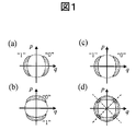
- FIG. 1 shows the principle for realizing it. It is assumed that legitimate transceivers share a seed key in advance, and the seed key is used to determine whether it is a q-axis basis or a p-axis basis.
- FIG. 1B shows a binary signal in the case of a p-axis basis.
- the legitimate receiver can be detected on the correct basis by the seed key, and in principle, binary determination can always be made in the state of fluctuation as shown in FIG. 1C, but the unauthorized receiver does not know the seed key, so FIG. It looks like a quaternary signal as shown in (d). As for the fluctuation of the quaternary signal, the overlap between adjacent ones increases, and the BER of the unauthorized recipient increases. Bit errors also occur in legitimate receivers, but the difference from unauthorized receivers is clear. This difference in bit error rate ensures a safe amount of information. The important point here is that an authorized receiver needs to make a binary decision from a quaternary signal, while an authorized recipient should make a binary decision from a binary signal. This difference produces a bit error rate difference. However, simply using the same key allows unauthorized recipients to estimate the basis, so it is a problem to devise a protocol that does not allow the basis estimation, and the present invention provides a solution to this.
- FIG. 2 shows an overview of the communication protocol according to the present invention.
- the layer 1 random numbers are transmitted and received using the fluctuation light. The safe amount of information is determined by the difference in BER between the legitimate recipient and the unauthorized recipient.
- the amount of random number data is reduced to a private key by a privacy amplifier (C. H. Bennett , G. Brassard, C. Crepeau, and U. U. Maurer, “Generalized privacy amplification,” IEEE Trans.Inf. Theory 41, 1915 (1995).).
- the layer 3 represents a normal signal transmission path, and uses the secret key obtained by the layer 2 to perform encrypted communication of the actual signal. In layer 3, it is not necessary to use fluctuation light.
- Layer 1 sends and receives random numbers on a random basis.
- the signal of the layer 1 is composed of only genuine random numbers including the base, no information is leaked even if it is illegally received.
- the regular sender / receiver shares the shared basis in advance with the seed key, and only the data of the slot that matches the shared basis is adopted as the random number signal among the random number signals transmitted on the random number basis. Since the legitimate receiver also has a bit error, the actual processing is somewhat complicated as shown in the following specific embodiment, but in principle, the binary signal is binary-determined thanks to the seed key. .
- the unauthorized receiver Since the unauthorized receiver must make a binary decision from the quaternary signal, the unauthorized receiver must receive random number data with a BER that is more disadvantageous than the authorized receiver. This difference in BER provides a safe amount of information between the legitimate sender and receiver, and a private key is obtained by the privacy amplifier (layer 2). The obtained secret key is extracted from the communication result using the seed key, but it is extracted from the difference in BER between the authorized recipient and the unauthorized recipient, and the extraction process is information-theoretic It is. This is important.
- Layer 3 is a normal communication path and may be exposed to various attacks such as known plaintext attacks and selected plaintext attacks.
- the layer 1 may be illegally received as a quaternary signal although there is a bit error. Therefore, there is a possibility that the ciphertext may be decrypted by comparing the illegal reception results of the layer 1 and the layer 3.
- the secret key is extracted based on the difference regarding the BER between the authorized receiver and the unauthorized receiver, the unauthorized reception results of the layer 1 and the layer 3 are uncorrelated in information theory. . Since the layer 1 transmits and receives only random number signals, the illegal recipient cannot obtain data such as the correspondence between the ciphertext and the plaintext.
- An illegal recipient can be obtained only with a true random number sequence except for the redundant portion of the error correction code. That is, when the amount of redundant information is removed by the privacy amplifier, there is no effective decryption method other than a brute force attack on the seed key. In order for an unauthorized receiver to realize decryption by an attack method that is more efficient than the brute force method, at least the layer 1 must be able to detect a random number signal with the same BER as the regular receiver. When this condition is satisfied, there is a possibility that a correlation appears between the unauthorized reception results of the layer 1 and the layer 3.
- the method of the present invention is one-step security improved over ordinary encryption.
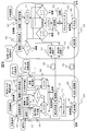
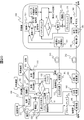
- FIG. 3 shows a configuration example of a cryptographic communication system according to the present invention.
- the transmitter 100 three random number generators (111, 112, 113) and two types of seed keys (121, 122) composed of random numbers are arranged.
- the random number generator and the seed key can be divided into one each by dividing the output from one random number generator into three parts and dividing one kind of seed key into two parts.
- the output of the random number generator 1 (111) is a random number that becomes a signal for generating a secret key, is encrypted using the seed key 2 (122), is encoded by the error correction encoder 141, and is stored in the buffer 131. Prepare to be sent.
- the buffer 132 prepares the output of the random number generator 2 (112) as a random number for the dummy signal.
- the random number generator 3 (113) converts the base into a random number, and the signal transmission of the layer 1 is performed based on the random number base.
- a base shared between legitimate senders and receivers must be used.
- the seed key 1 (121) is used.
- the base is completely randomized by the random number generator 3 (113), but not all the random numbers transmitted and received are used as signals, but the random number base matches the base determined by the seed key 1 (121) It is assumed that random numbers are seen by unauthorized recipients, but regular recipients are seen by regular recipients.
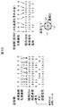
- FIG. 4 shows a specific example of the random number signal and the dummy random number processed by the above mechanism.
- the q-axis base in FIG. 1 is set to “0”, and the p-axis base is set to “1”.
- the random number base determined by the output of the random number generator 3 (113) is 010011101000100 as shown in FIG.
- the base shared in advance between the sender and the receiver is 110100001101100.
- the first basis of the shared basis is “1”, but the first of the random number basis determined by the random number generator 3 (113) is “0”, which is inconsistent.
- a dummy random number A signal is transmitted by superimposing a standby in the buffer 132.
- the superimposition of the signal is performed through the modulator 161 on the output light from the fluctuation light source 151.
- the second output of the random number base (random number generator 3 (113)) is “1”.
- the random number signal (waiting in the buffer 131) is superimposed and transmitted. To do. Since the next shared basis and random number basis are both “0”, the random number signal is continuously superimposed and transmitted. Thereafter, the same is repeated.
- the timing at which the random number signal and the dummy random number are superimposed is determined depending on the output of the random number base (random number generator 3 (113)), so that the buffer 131 and the buffer 132 as shown in FIG. And waiting for a random number signal and a dummy random number. Since the signal (random signal and dummy random number) is binary and the base is also binary, the signal at the time of transmission is quaternary. In the column of “Transmission signal” in FIG. 4, signal values at the time of allocation in the phase space as shown in the lower left diagram are described. The random number in the “Signal” column is a random number signal, and the random number in the “Dummy” column is a dummy random number. Note that the random number data is error-corrected and encoded by an error correction encoder 141 in order to correct a bit error that occurs for a legitimate receiver.
- Signals (random number signals and dummy random numbers) are transmitted through the optical transmission line 201 and received by the detector 311 in the receiver 300.
- the detector 311 performs quaternary determination and binary determination simultaneously. This process is easy.
- Two quadrature components (q-axis component and p-axis component) are measured by two sets of homodyne detectors.
- a binary determination result for each base is obtained by performing binary determination (each component is positive or negative) on the output values I q and I p of each homodyne detector.
- phase ⁇ is determined by arctan (I p / I q ) from the output values I q , I p of the two sets of homodyne detection results, four-value determination (“0”, “1”, “2”, “3”: (See FIG. 4). Since the base is randomized, the signal state appears to be four values even for a legitimate receiver. Therefore, it is first determined which base was used by determining four values. If the quaternary determination result is “0” or “2”, the base “0” is determined, and if the quaternary determination result is “1” or “3”, the base “1” and the random number base are determined.
- the parity check function of the error correction code incorporated in the random number signal is used. If there is no error in the collation between the random number basis and the shared basis, the BER of the random number data becomes a small value estimated in advance, but if there is an error in the collation, a bit error will occur with a probability of 1/2 after the bit in which the error occurred. Therefore, the position where the bit error starts by the parity check can be almost specified. The position where this bit error has started is either whether a dummy random number has entered or the random number signal has dropped out. Therefore, the parity check is performed by removing the bit at the position where the bit error has started, and the parity check is performed by returning the bit discarded because it is determined to be a dummy, and a bit string almost free of bit errors is searched.
- FIG. 4 shows a specific example of what happens when there is a bit error.
- a rudimentary parity check bit is inserted in error correction coding by the error correction encoder 141. It is assumed that random number data is divided every 5 bits, and if the number of “1” is an odd number, it is “1”, and if it is an even number, it is “0”. The random number signal is shown in the “Signal” column on the transmission side in FIG. Parity for 5 bits from the left is inserted in the 6th bit. In FIG. 4, the parity bits are shown in italics. If there is no bit error during reception, the calculated parity of the received random number signal matches the value of the parity bit.
- the bit with the underline added is a determination error.
- bits that are not originally signal bits are treated as signal bits, and the shared random number increases by one bit.
- the position of the parity check bit is shifted by 1 bit (on the receiving side in FIG. 4, the bit that the receiver recognizes as the parity bit is in italics.
- the bit is shifted by 1 bit depending on whether there is a bit error or not. ).
- the receiver performs a parity check without noticing that one bit has been shifted, the parity will not match with probability 1/2 after the bit in which the bit error has occurred. This makes it possible to roughly determine where a bit error has occurred.
- the determination of the random number base of the bit that seems to be a bit error is changed and the processing of the receiver is repeated, and a bit string in which the parity is almost normal is searched. In the example on the receiving side in FIG. 4, an underlined bit is an error, and this bit is deleted from the shared random number, so that the bit error-free state can be restored.
- the base collation is incorrect, and therefore, when returning, signal determination is performed based on a base different from the initial determination.
- the signal determination at this time is binary determination because the base is fixed.
- the processing in the receiver of this system is temporarily determined in four values, but is reduced to binary determination in the process of correcting the base determination error.
- the BER is smaller than in the case of 4-level determination. This is a factor in which the legitimate receiver becomes informationally advantageous to the illegal receiver, and is brought about by the seed key 1 (121 and 321) shared in advance between the sender and the receiver.
- the error correcting code is decoded and the seed key 2 (322) is decoded.
- the output of the random number generator 1 (111) in the transmitter can be reproduced in the receiver.
- the privacy amplifier (171 and 371) reduces the information amount of the random number signal shared between the sender and the receiver to the corrected information amount.
- the privacy amplifier can be realized through logical operations, for example. It is assumed that 20% of the random numbers shared between the sender and the receiver is a safe amount of information, and the shared random number is '01001 01110'. If an exclusive OR is performed every 5 bits, it becomes “01”. In this process, all data are handled equally and the amount of information is reduced to 20%. This is an example of a privacy amplifier.
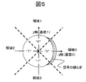
- the BER of regular recipients and unauthorized recipients can be estimated as follows. As shown in FIG. 5, the directions of “0” and “1” of each base are assigned. If the signal state is taken as the signal “0” of the q-axis base (base “0”), the authorized receiver who knows that it is the q-axis base determines whether the measured value is on the right or left side with the p-axis as the boundary. do it. A bit error occurs when the authorized receiver obtains a measured value in the negative region of the q axis with respect to the signal “0”. If the fluctuation spread is sufficiently large compared to the quantum fluctuation and the classical handling of measurement is possible, the probability distribution of the signal “0” on the q-axis basis is given by the phase-related function P ( ⁇ ). The BER of the authorized recipient is described by the equation (1).
- An unauthorized recipient will make a binary decision from a signal that appears to be quaternary, and if it finds a measurement value in areas 0 and 1, it will decide that the signal is “0”, and if it finds a measurement value in areas 2 and 3, it will Since it is determined as “1”, a bit error occurs when the measurement value is found in the region 2 and the region 3 for the signal “0”. Therefore, the BER of the unauthorized recipient is given by equation (2).
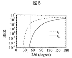
- Probability distribution of the fluctuation P (theta) is, if using the magnitude ⁇ fluctuations given by equation (3), specifically the legitimate receiver bit error rate E B and unauthorized recipients bit error rate E E Can be requested.
- FIG. 6 is a plot of E B and E E with 2 ⁇ as a variable. If the fluctuation of the Gaussian distribution is set so that the BER of the regular receiver is 10 ⁇ 12 , the BER of the illegal receiver is about 10 ⁇ 4 .
- the error correction code (141) applied to the random number signal (111) does not need to be able to correct an error in the case of quaternary determination (two-base binary determination). In the base collation process in the receiver, it is only necessary to determine only positions where bit errors occur continuously. If the bit at the starting point of the continuous bit error can be specified, by correcting the bit, the BER is reduced to an expected value when the binary determination (one base binary determination) can be performed. On the contrary, if error correction can be performed with respect to quaternary determination (binary binary determination), the difference in BER based on the effect of fluctuation between the regular receiver and the illegal receiver is lost. That is, there is no difference between an authorized recipient who is guaranteed in terms of information theory and an unauthorized recipient.
- an authorized recipient for example, BER
- an error correction code is designed so that the continuous bit error starting points generated in the base matching process can be determined as easily as possible.
- the signal transmitted / received by the layer 1 is a random number, and the base is determined by a true random number.
- the random number signal is encrypted with the seed key 2 (122)
- the seed key 2 (122) is not estimated by an unauthorized recipient because the signal is a random number. Since the seed key 1 (121) for determining the shared base is also buried in the random number base, an unauthorized recipient cannot be estimated here either. Since the illegal receiver cannot obtain meaningful information in the layer 1, the difference in BER formed between the legitimate receiver and the illegal receiver leads to a safe amount of information. However, it is necessary to correct the error correction code with redundancy. If the privacy amplifier executor 171 in the transmitter 100 and the privacy amplifier executor 371 in the receiver 300 operate with the same algorithm, a common secret key is formed between the transceivers.
- the actual signal is encrypted by the encryptor 181 using the secret key generated in the transmitter, superimposed on the carrier light by the optical transmitter 182, and transmitted to the receiver 300 by the optical transmission line 202.
- the optical transmitter 182 includes a light source and a modulator that modulates light emitted from the light source.
- the receiver 300 receives the transmitted signal light by the photodetector 381 and converts it into an electrical signal, and the encryption / decryption device 382 uses the secret key to make a plain. This completes a series of secure cryptographic communication processes.
- the communication performed on the optical transmission line 202 does not need to use carrier light with fluctuation, and may be normal optical communication.
- the optical transmission lines 202 and 201 may be physically different, or wavelength multiplexing may be performed using the same optical transmission line.
- Example 1 the random number base and the shared base are compared in pairs for each bit, and it is determined whether to transmit a random number signal or a dummy random number.
- a method other than the first embodiment is also possible as a method for selecting the shared basis from the random number basis, and FIG. 7 shows an example of the configuration of a cryptographic communication system that realizes the method.
- the shared basis and the random number basis are collated to determine which of the random number signal and the dummy random number is transmitted, as in the first embodiment.
- the shared base and the random number base do not match, the shared base that has not been adopted is checked again with the random number base at the next bit to determine whether to transmit a random number signal or a dummy random number.
- the shared basis is repeated until it matches the random number basis. In other words, the operation is performed so that the sequence of bases on which the random number signal is superimposed is aligned with the shared bases.
- FIG. 8 shows the above mechanism as a specific example.
- the random number base determined by the output of the random number generator 3 (113) is 00011101000100 in FIG.
- the base shared in advance between the sender and receiver by the seed key 1 (121, 321) made up of random numbers is 10110000.
- preparations are made for transmitting random number signals in a sequence of bases determined by shared bases.
- the first base of the shared base is “1”, but the first of the random base determined by the random number generator 3 (113) is “0”, which is inconsistent.
- a signal is transmitted by superimposing a dummy random number (output of the random number generator 2 (112)).
- the shared basis “1” that was not matched is checked again with the next random number basis.
- the second output of the random number base (random number generator 3 (113)) is “1”.
- the random number signal is superimposed and transmitted.
- the random number signal is subjected to error correction coding in the same manner as in the first embodiment, and for simplification, a parity bit is added every 5 bits as in the first embodiment. On the transmission side in FIG. 8, the parity bits are italicized.
- the processing on the receiver 300 side is also modified from the processing in the first embodiment based on the modification of the processing on the transmitter 100 side.
- quaternary determination is performed to determine which base is used in the same manner as in the first embodiment. This is compared with the shared basis, and if it matches, the random number data is adopted, and if it does not match, it is determined as a dummy random number.
- the shared base that did not match is checked again with the random number base determined from the received signal next, and if it matches, the base and the random number data are adopted.
- the parity after that position becomes an error with a probability of 1/2, and the position where the determination error has occurred is almost specified.
- the position where this determination error occurred is either a dummy random number entered or the random number signal dropped out, so remove the bit near the position where the determination error occurred and repeat the base verification after that position to check the parity again.
- perform a parity check by returning the bits that were discarded because it was determined to be a dummy near the position where there was a determination error, and performing the base check again after that position, and a bit string with almost no bit errors look for.
- An example where there is no bit error and when there is no bit error is shown on the right side of FIG.
- the base verification of the second bit from the left results in a determination error (indicated by an underline on the receiving side), and the random number signal that should originally be a shared random number is determined as a dummy random number. For this reason, the number of bits of the adopted data is reduced, the position of the parity bit is shifted, and the shared random number is completely different.
- FIG. 8 it can be seen that when there is a basis determination error, the slot position of the shared random number changes so as not to retain the original pattern. In this case, the subsequent parity bits are erroneous with a probability of 1 ⁇ 2, and the position where the bit error occurred can be generally understood. If the position of the bit error can be almost specified, the bits in the vicinity thereof are corrected, and the correction is repeated until the bit error is almost eliminated and a BER that enables decoding of the error correction code is reached.
- the protocol shown in FIG. 9 uses three random number generators (111, 112, 114) and three seed keys (122, 123, 124) made up of random numbers. Similar to the first embodiment, there is a method in which the output of one random number generator and one seed key are divided into three parts.
- the arrangement of slots for sending random number signals and slots for sending dummy random numbers is determined by true random numbers using the random number generator 3 (113), but is determined by the pseudo random number generator 124 in this embodiment.
- the base of the slot for transmitting the random number signal (output of the random number generator 1 (111)) is a shared base determined by the pseudo random number generator 123, and the slot of the slot for transmitting the dummy random number (output of the random number generator 2 (112)).
- the base is determined by the random number generator 3 (114). In the present embodiment, it is determined in advance between the sender and the receiver by the seed key 2 (pseudorandom number generator 124) which slot of the transmission signal is embedded with the random number signal.
- the transmission base is no longer a true random number, and the security is inferior to that of the first and second embodiments, but the data processing becomes easy.
- FIG. 10 shows a specific example of the base and random number signal processing.
- the shared base determined by the pseudo random number generator 123 is 10110000, and the random base determined by the random number generator 3 (114) is 0010111. It is the output 000111101000101 of the pseudo random number generator 124 that determines the arrangement of these two types of base information (the column “adopted slot” on the left side of FIG. 10).
- the shared basis is the transmission basis
- the random number basis is the transmission basis.
- the transmission base of the result is 100101011000101.
- the basis seen by the unauthorized recipient is a sequence of genuine random numbers (random number generator 3 (114)) and pseudorandom numbers (pseudorandom number generator 123) arranged using another pseudorandom number (pseudorandom number generator 124), Although pseudorandom number generators 123 and 124 are used, it is difficult to decipher the basis of each signal. Whether the random number signal is transmitted or the dummy random number is transmitted is determined by the pseudo random number generator 124, and the buffers 133 and 134 are provided as in the first and second embodiments so that the signal can be transmitted in accordance with the timing. .
- the buffers 133 and 134 temporarily stand by each of these pairs.
- the point that the random number signal (the output from the random number generator 1 (111)) is encrypted by the seed key 3 (122) and the point that the error correction encoding (141) is performed are the same as in the first and second embodiments. It is the same that the transmission signal appears to have four values.
- the receiver performs projection detection on the q-axis base (base “0”) and the p-axis base (base “1”) using two sets of homodyne detectors 312 and 313, and performs binary determination. Only the detection result of the slot whose output of the pseudo random number generator 324 (the same as the output of the pseudo random number generator 124) corresponds to “0” is processed as the received random number, and the dummy slot (the output of the pseudo random number generator 324 is “ 1 ”) signal is ignored. Since the basis of the random number signal is determined by the output of the pseudo random number generator 323 (the same as the output of the pseudo random number generator 123), it is determined which of the two sets of homodyne outputs is to be adopted.
- the output of the pseudo random number generator 324 that determines the slot of the shared base is synchronized with the transmission clock, so the random number signal is a part of the transmitted signal, so the output of the pseudo random number generator 323 that determines the shared base is the buffer 333. Wait for a while and adjust to the timing when the random number signal comes. Based on the output (shared base) of the pseudo-random number generator 323, the output of one of the two photodetectors 312 and 313 is adopted, and the output value (shared random number) is input to the buffer 334, and the output timing is adjusted. The data is input to the error correction code decoder 341.
- the cipher is decrypted with the seed key 3 (322) (the same as the seed key 3 (122)), and the output of the random number generator 1 (111) in the transmitter is reproduced.
- the random number signal can be shared between the transmitter and the receiver, the processing by the privacy amplifier executors (171 and 371) is performed in both the transmitter and the receiver, and the secret key is shared.
- the actual signal encryption communication using the secret key is the same as in the first and second embodiments.
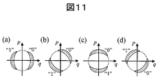
- FIG. 11 is a diagram illustrating a signal state on the phase space in the case of the binary 4-base phase modulation method.
- FIG. 11A shows a binary signal based on the q-axis
- FIG. 11B shows a binary signal based on 45 ° rotated from the q-axis.
- FIG. 11 (c) shows a p-axis base binary signal
- FIG. 11 (d) shows a base binary signal rotated ⁇ 45 ° from the q-axis.
- FIG. 12 is a diagram illustrating a signal state on the phase space in the case of the quaternary two-basis phase modulation method.
- 12A shows a quaternary signal based on the q-axis and the p-axis
- FIG. 12B shows a quaternary signal rotated by 45 ° from the case of FIG. 12A.
- the fluctuation light source 151 which is an element common to each embodiment will be described.
- Various forms of the fluctuation light source 151 are conceivable, but a method using the Kerr effect of an optical fiber is convenient.
- An example is shown in FIG.
- the output light from the laser light source 1510 is amplified by the optical amplifier 1521, passes through the band filter 1522, and propagates through the optical fiber 1523.
- phase fluctuation is applied through the Kerr effect of the optical fiber.
- the laser output light can be described relatively well in the coherent state, and the shape of the fluctuation in the phase space is circular, but it becomes elliptical through the Kerr effect of the optical fiber, and further progresses into a crescent shape.
- Such light with an elliptical or crescent shape is called anti-squeezed light (T. Tomaru, and M. Ban, “Secure optical communication using antisqueezing,” Phys. Rev. A 74, 032312 (2006 ), T. Tomaru, “LD lightqueantisqueezing through fiber propagation in reflection-type interferometer,” Opt. Exp. 15, 11241 (2007)). Since the Kerr effect increases in proportion to the light intensity, it is effective to increase the peak intensity using pulsed light.
- the pulse width, the light intensity, and the fiber dispersion value so as to satisfy the soliton condition (Japanese Patent Laid-Open No. 2008-003339). Further, if the light intensity is increased further than the above soliton condition, it becomes possible to satisfy the condition of higher-order solitons (Japanese Patent Laid-Open No. 2008-003339), and the pulse width reduction effect works and enhances the Kerr effect. it can. Further, at that time, the spectrum width is expanded, and the spectrum expansion exhibits the same effect as the phase fluctuation in phase detection, so that the effect of the fluctuation is further enhanced. Similar to the Kerr effect, the Raman effect is also effective in expanding phase fluctuations.
- FIG. 14 shows an embodiment in which a fiber propagation part is reciprocated using an optical circulator 1524 and a Faraday mirror 1525.
- the advantage is that the fiber length can be halved. Also, since the polarization rotates exactly 90 degrees when the fiber 1523 is reciprocated once regardless of the polarization state during fiber propagation, it is effective when it is desired to stabilize the polarization at the time of fluctuation generator output. It is also effective to increase the effect of phase fluctuation by incorporating a fiber interferometer in fluctuation generator 1520 and increasing the ratio of phase fluctuation to amplitude (T. Tomaru, “LD light antisqueezing through fiber propagation in reflection-type interferometer, ”Opt. Exp. 15, 11241 (2007)).
- the above is what caused the phase fluctuation by the Kerr effect of the optical fiber. It is also possible to output light accompanied by phase fluctuation directly from a laser diode (LD). If the LD is operated near the oscillation threshold, the phase fluctuation is large. It is one method to use this property as it is.
- LD laser diode
- An injection current is required for LD oscillation. It is also possible to superimpose fluctuations (noise) on the injected current to generate the same effect as the fluctuation of the light source itself.
- FIG. 15 shows such a case.
- a fluctuation generation source for example, use of thermal fluctuation can be considered.
- the output of the random number generator can be multivalued to make it equivalent to fluctuation.
- the superimposition of fluctuation can also be performed in the modulator 161.
- the modulator 161 is installed for signal superimposition. If the fluctuation is superimposed simultaneously with the signal superimposition, the modulator 161 works equivalent to the case where the light source fluctuates (FIG. 16).
- the fluctuation generation source 1630 it is conceivable to use thermal fluctuation, to make the output of the random number generator multivalued, and to make it equivalent to fluctuation.
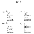
- FIG. 17 shows the state of the intensity distribution function when operating on a binary binary basis.
- the signal intensity of “0” and “1” varies depending on the base.
- FIG. 17A and FIG. 17B are binary signals when the bases are different. Due to the difference in the basis, the threshold values of “0” and “1” are different between FIG. 17A and FIG.
- the signal state has a total of four values as shown in FIG. Since there is an overlap in the probability distribution, bit errors increase.
- the regular receiver who knows the base may make a quaternary determination once in the determination process as in the first and second embodiments. However, since a binary determination can be made in principle, as shown in FIG. Binary determination can be performed with almost no overlapping distribution.
- Binary decision and quaternary decision are the same for the phase modulation method and the intensity modulation method. Therefore, the signal processing for the phase modulation method shown in the first to third embodiments can be similarly performed for the case of the intensity modulation method.
- the embodiments of the present invention have been described above using the phase modulation method as a main example. However, as mentioned in the fifth embodiment, the present invention is established without distinction between the phase modulation method and the intensity modulation method.
- the embodiment has been described mainly taking the binary base as an example, as described with reference to FIGS. 11 and 12, the present invention can also be applied to a case of a multi-value multi-base.
- an error correction code is used for correcting a bit error that remains slightly even for a legitimate receiver and for correcting a base collation error in the receiver.
- the random number data made redundant by the error correction code is transmitted through the optical transmission line 201 shown in FIGS.
- the optical transmission line 201 it is ideal that a random number signal is transmitted on a random number basis. Therefore, consider transmitting the error correction code redundancy by the optical transmission line 202. As a result, only a complete random number signal is transmitted to the optical transmission line 201.
- the optical transmission line 202 is a normal transmission line, there is no safety for redundancy, but the amount of information for redundancy is originally subtracted from the amount of safe information in the process of secret key generation, so this is not a problem.
- the parity check function inherent in the error correction code is used to determine the basis, the basis verification error is corrected based on the result of the parity check, and the random number signal and the dummy random number are obtained. I was identifying.
- the signal redundancy is also transmitted as a series of data together with the random data, so it is not determined at the first processing stage of the receiver which is the random data and which is the redundancy.
- the redundant part was fixed while correcting the base verification error. Therefore, the data processing has to be complicated.
- the redundant part is transmitted through the optical transmission line 202, the redundant part data for the parity check is fixed and reaches the receiver without fail, so the complexity of the base determination process in the receiver is reduced, and the circuit implementation When doing so, calculation time and calorific value are alleviated.
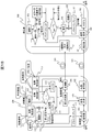
- FIG. 18 shows a configuration example of a cryptographic communication system according to the present invention.
- the transmitter 100 three random number generators (111, 112, 113) and two kinds of seed keys (121, 122) composed of random numbers are arranged.
- the random number generator and the seed key can be divided into one each if the output from one random number generator is divided into three parts and one kind of seed key is divided into two parts.
- the output of the random number generator 1 (111) is a random number that becomes a signal for generating a secret key, is encrypted using the seed key 2 (122), and is encoded by the error correction encoder 141.
- an information symbol portion and a parity check symbol portion are separated, and the former is called a random number code and the latter is called a check symbol.
- the random number code is prepared for transmission in the buffer 131.
- the buffer 132 prepares the output of the random number generator 2 (112) as a random number for the dummy signal.
- the random number generator 3 (113) converts the base into a random number, and the signal transmission of the layer 1 is performed based on the random number base.
- the seed key 1 (121) is used.
- the base is completely randomized by the random number generator 3 (113), but not all the random numbers transmitted and received are used as signals, but the random number base matches the base determined by the seed key 1 (121) It is assumed that random numbers are seen by unauthorized recipients, but regular recipients are seen by regular recipients.
- FIG. 19 A specific example of the random number signal and the dummy random number processed by the above mechanism is shown in FIG.
- the q-axis base in FIG. 1 is set to “0”, and the p-axis base is set to “1”.
- the random number base determined by the output of the random number generator 3 (113) is assumed to be 010011101000100 as shown in FIG.
- the base shared in advance between the sender and the receiver is 110100001101100.
- the first basis of the shared basis is “1”
- the first of the random number basis determined by the random number generator 3 (113) is “0”, which is inconsistent.
- a dummy random number A signal is transmitted by superimposing a standby in the buffer 132.
- the superimposition of the signal is performed through the modulator 161 on the output light from the fluctuation light source 151.
- the second output of the random number base (random number generator 3 (113)) is “1”.
- the random number code (waiting in the buffer 131) is superimposed and transmitted. To do. Since the next shared basis and random number basis are both “0”, the random number code is continuously superimposed and transmitted. Thereafter, the same is repeated.
- the timing at which the random number code and the dummy random number are superimposed is determined depending on the output of the random number base (random number generator 3 (113)). Therefore, as shown in FIG. And waiting for a random number code and a dummy random number. Since the signal (random number code and dummy random number) is binary and the base is also binary, the signal at the time of transmission is quaternary.
- the column of “Transmission signal” in FIG. 19 signal values when allocation in the phase space as shown in the lower left diagram is described.
- the random number in the “Signal” column is a random number code
- the random number in the “Dummy” column is a dummy random number.
- the “parity check” column represents a parity check symbol. Here, as an example, the parity for every 5 bits of the random number signal is treated as a check symbol.
- the parity check symbol generated by the error correction encoder 141 is multiplexed with other signals sent on the normal transmission line in the signal processing unit 183 for transmission on the normal optical transmission line 202.
- This multiplexing is a method performed in normal communication such as packetization or time multiplexing. Thereafter, the light is guided to the optical transmitter 182 and transmitted to the receiver 300 through the optical transmission path 202. Light is received by the photodetector 381, converted into an electrical signal, and sent to the signal processing unit 383.
- the signal processing unit 383 separates the multiplexed signal sequence into a state before multiplexing, and the check symbol is separated from other signals here.
- the signals (random code and dummy random number) are transmitted by the optical transmission line 201 and received by the detector 311 in the receiver 300.
- the detector 311 performs quaternary determination and binary determination simultaneously. This process is easy.
- Two quadrature components (q-axis component and p-axis component) are measured by two sets of homodyne detectors.
- a binary determination result for each base is obtained by performing binary determination (each component is positive or negative) on the output values I q and I p of each homodyne detector.
- phase ⁇ is determined by arctan (I p / I q ) from the output values I q , I p of the two sets of homodyne detection results, four-value determination (“0”, “1”, “2”, “3”: (See FIG. 19). Since the base is randomized, the signal state appears to be four values even for a legitimate receiver. Therefore, it is first determined which base was used by determining four values. If the quaternary determination result is “0” or “2”, the base “0” is determined, and if the quaternary determination result is “1” or “3”, the base “1” and the random number base are determined.
- a parity check symbol transmitted through the optical transmission line 202 is used. If there is no error in the collation between the random number basis and the shared basis, the BER of the random number data becomes a small value estimated in advance, but if there is an error in the collation, a bit error will occur with a probability of 1/2 after the bit in which the error occurred. Therefore, if a parity check is performed, the position where the bit error has started can be almost specified. The position at which this bit error has started is either a dummy random number has been entered or the random number code has been dropped. Therefore, the parity check is performed by removing the bit at the position where the bit error has started, and the parity check is performed by returning the bit discarded because it is determined to be a dummy, and a bit string almost free of bit errors is searched.
- FIG. 19 also shows a specific example of what happens when there is a bit error.
- error correction coding with an elementary parity check function is performed in the error correction encoder 141. Random number data is divided every 5 bits. If the number of “1” is odd, “1” is used, and if it is even, “0” is used as a check symbol. The random number code is shown in the “Signal” column on the transmission side in FIG. The parity for 5 bits from the left is 1 and is shown in the “parity check” column. If there is no bit error at the time of reception, the calculated parity of the received random number code matches the value of the check symbol.
- the determination of the random number base on the receiving side is incorrect at the sixth bit from the left in FIG.
- the bit with the underline added is a determination error.
- bits that are not originally signal bits are treated as signal bits, and the shared random number increases by one bit.
- the receiver performs a parity check without noticing that one bit has been increased, the parity will not match with a probability of 1/2 after the bit in which the bit error has occurred. This makes it possible to roughly determine where a bit error has occurred.
- the determination of the random number base of the bit that seems to be a bit error is changed and the processing of the receiver is repeated, and a bit string in which the parity is almost normal is searched. In the example on the receiving side in FIG. 19, an underlined bit is an error, and this bit is deleted from the shared random number, so that the bit error-free state can be restored.
- the base collation is incorrect, and therefore, when returning, signal determination is performed based on a base different from the initial determination.
- the signal determination at this time is binary determination because the base is fixed.
- the processing in the receiver in this system is temporarily determined in four values, but is reduced to binary determination in the process of correcting the base error.
- the BER is smaller than in the case of 4-level determination. This is a factor in which the legitimate receiver becomes informationally advantageous to the illegal receiver, and is brought about by the seed key 1 (121 and 321) shared in advance between the sender and the receiver.
- the error correcting code is decoded and the seed key 2 (322) is decoded.
- the output of the random number generator 1 (111) in the transmitter can be reproduced in the receiver.
- the privacy amplifier (171 and 371) reduces the information amount of the random number signal shared between the sender and the receiver to the corrected information amount.
- the privacy amplifier can be realized through logical operations, for example. It is assumed that 20% of the random numbers shared between the sender and the receiver is a safe information amount and the shared random number is ‘01001 01110’. If an exclusive OR is performed every 5 bits, it becomes “01”. In this process, all data are handled equally and the amount of information is reduced to 20%. This is an example of a privacy amplifier.
- the BER of regular recipients and unauthorized recipients can be similarly estimated by the method described in the first embodiment. As shown in FIG. 6, if the fluctuation of the Gaussian distribution is set so that the BER of the regular receiver is 10 ⁇ 12 , the BER of the unauthorized receiver is about 10 ⁇ 4 .
- the error correction code (141) applied to the random number signal (111) does not need to be able to correct an error in the case of quaternary determination (two-base binary determination). In the base collation process in the receiver, it is only necessary to determine only positions where bit errors occur continuously. If the bit at the starting point of the continuous bit error can be specified, the bit is corrected, so that the BER is reduced to an expected value when binary (one base binary) can be determined. On the other hand, if error correction can be performed with respect to quaternary (binary binary) determination, the difference in BER based on the effect of fluctuations between the regular recipient and the unauthorized recipient is lost. That is, there is no informationally guaranteed difference between the legitimate recipient and the illegal recipient.
- the ability of an error correction code applied to a random number signal is judged as a regular recipient (one base binary signal determination) For example, it is necessary that the BER is 10 ⁇ 12 ), and that it is insufficient for an unauthorized receiver (for example, the BER is 10 ⁇ 4 ) that needs to determine a signal with a binary basis. Furthermore, it is desirable that the error correction code is designed so that the continuous bit error starting points generated in the base matching process can be determined as easily as possible.
- the signal transmitted and received on the optical transmission line 201 is a random number, and the base is also determined by a true random number.
- the random number signal is encrypted with the seed key 2 (122)
- the seed key 2 (122) is not estimated by an unauthorized recipient because the signal is a random number. Since the seed key 1 (121) for determining the shared base is also buried in the random number base, an unauthorized recipient cannot be estimated here either. Since the illegal receiver cannot obtain meaningful information on the optical transmission line 201, the difference in BER formed between the regular receiver and the illegal receiver brings a safe amount of information. However, it is necessary to correct the error correction code with redundancy. If the privacy amplifier executor 171 in the transmitter 100 and the privacy amplifier executor 371 in the receiver 300 operate with the same algorithm, a common secret key is formed between the transceivers.
- the actual signal is encrypted by the encryptor 181 using the secret key generated in the transmitter, multiplexed with other signals by the signal processing unit 183, and superimposed on the carrier light by the optical transmitter 182 for optical transmission. It is transmitted to the receiver 300 through the path 202.
- the optical transmitter 182 includes a light source and a modulator that modulates light emitted from the light source.
- the receiver 300 receives the transmitted signal light by the photodetector 381 and converts it into an electrical signal.
- the electrical signal is returned to the state of the signal before multiplexing by the signal processing unit 383, and the encrypted signal is received.
- the separated and encrypted signal is decrypted in the decryptor 382 using the secret key. This completes a series of secure cryptographic communication processes.
- the communication performed on the optical transmission line 202 does not need to use carrier light with fluctuation, and may be normal optical communication.
- the optical transmission lines 202 and 201 may be physically different, or wavelength multiplexing may be performed using the same optical transmission line.
- Example 6 the random number base and the shared base are compared in pairs for each bit, and it is determined whether to transmit a random number code or a dummy random number.
- a method other than the sixth embodiment is also possible as a method for selecting a shared basis from among random number bases, and FIG. 20 shows a configuration example of a cryptographic communication system that realizes the method.
- the present embodiment is the same as the method of the sixth embodiment in that the shared basis and the random number basis are collated to determine which of the random number code and the dummy random number is transmitted. However, if the shared base and the random number base do not match, the shared base that has not been adopted is checked again with the random number base at the next bit to determine whether to transmit a random number code or a dummy random number. The shared basis is repeated until it matches the random number basis. In other words, the operation is performed so that the sequence of bases on which the random number codes are superposed coincides with that of the shared bases.
- FIG. 21 shows the above mechanism as a specific example.
- the random number base determined by the output of the random number generator 3 (113) is 010011101000100 in FIG.
- the base shared in advance between the sender and receiver by the seed key 1 (121, 321) made up of random numbers is 10110000.
- preparations are made for transmitting random number signals in a sequence of bases determined by shared bases.
- the first basis of the shared basis is “1”, but the first of the random number basis determined by the random number generator 3 (113) is “0” and does not match.
- a signal is transmitted by superimposing a dummy random number (output of the random number generator 2 (112)).
- the shared basis “1” that was not matched is checked again with the next random number basis.
- the second output of the random number base (random number generator 3 (113)) is “1”.
- the random number code is superimposed and transmitted.
- the random number signal is subjected to error correction coding in the same manner as in the sixth embodiment, and is separated by the error correction encoder 141 into a random number code in the information symbol portion and a redundant parity check symbol. For simplification, the parity for every 5 bits is a check symbol as in the sixth embodiment.
- the processing on the receiver 300 side is also modified from the processing of the sixth embodiment based on the modification of the processing on the transmitter 100 side.
- quaternary determination is performed, and which base is used is the same as in the method of the sixth embodiment. This is compared with the shared base, and if it matches, the random number data is adopted as a random number code, and if it does not match, it is determined as a dummy random number.
- the shared base that did not match is checked again with the random number base determined from the received signal next, and if it matches, the base and the random number data are adopted. If there is a base determination error, the parity after that position becomes an error with a probability of 1/2, and the position where the determination error has occurred is almost specified.
- the position where this determination error occurred was either a dummy random number entered or the random number code was missing, so remove the bits near the position where the determination error occurred and repeat the base verification after that position to perform the parity check again.
- perform a parity check by returning the bits discarded because it was determined to be a dummy near the position where there was a determination error, and performing the base check again after that position, and a bit string with almost no bit errors look for. Examples of cases where there is no basis determination error and cases where there is no basis determination are shown on the right side of FIG.
- the base verification of the second bit from the left results in a determination error (indicated by an underline on the receiving side), and the random number signal that should originally be a shared random number is determined as a dummy random number. For this reason, the number of bits of the adopted data is reduced, and the shared random number is completely different.
- the slot position of the shared random number changes so as not to remain the original when there is a basis determination error.
- the subsequent parity check is erroneous with a probability of 1 ⁇ 2, and the position where the bit error occurred can be generally understood. If the position of the bit error can be almost specified, the bits in the vicinity thereof are corrected, and the correction is repeated until the bit error is almost eliminated and a BER that enables decoding of the error correction code is reached.
- a secure secret key can be generated using the seed key as a starting hand and using fluctuations.
- the present invention is based on the seed key, the process of generating the secret key is guaranteed in terms of information theory. Therefore, even if an unauthorized recipient tries to decipher the ciphertext, there is no effective attack method other than a brute force attack on the seed key. In other words, it is freed from the threat that an efficient cryptanalysis method may be discovered.
- the system according to the present invention can use the current optical communication network as it is, and is a realistic and highly applicable system. For these two reasons, the present invention has high industrial applicability.
Landscapes
- Engineering & Computer Science (AREA)
- Computer Networks & Wireless Communication (AREA)
- Signal Processing (AREA)
- Physics & Mathematics (AREA)
- Computer Security & Cryptography (AREA)
- Electromagnetism (AREA)
- Theoretical Computer Science (AREA)
- Optics & Photonics (AREA)
- Optical Communication System (AREA)
Abstract
Description
111~114 乱数発生器
121,122 種鍵
123,124 擬似乱数発生器
131~134 バッファ
151 揺らぎ光源
161 変調器
171 プライバシアンプ実行器
181 暗号器
182 光送信機
183 信号処理部
201,202 光伝送路
300 受信機
311~313 光検出器
321,322 種鍵
323,324 擬似乱数発生器
333,334 バッファ
341 誤り訂正復号器
371 プライバシアンプ実行器
381 光検出器
382 暗号復号器
383 信号処理部
1510 レーザー
1520 揺らぎ生成器
1521 光アンプ
1522 帯域透過フィルタ
1523 光ファイバ
1524 サーキュレータ
1525 ファラデーミラー
1530,1630 揺らぎ発生源



Claims (14)
- 第1の乱数発生器、誤り訂正符号器、第2の乱数発生器、第3の乱数発生器、第1の光源、第1の変調器、プライバシアンプ、暗号器、並びに第2の光源及び第2の変調器を有する光送信機を具備する送信機と、
第1の光検出器、誤り訂正復号器、プライバシアンプ、第2の光検出器、及び暗号復号器を具備する受信機と、
前記送信機と前記受信機をつなぐ光伝送路とを有し、
前記送信機と前記受信機は予め乱数からなる第1の種鍵を共有し、前記第1の種鍵は前記送信機と前記受信機に共有基底を与え、
前記送信機は、前記第1の乱数発生器の出力を乱数信号として前記誤り訂正符号器によって誤り訂正符合化し、
前記第2の乱数発生器の出力をダミー乱数とし、前記第3の乱数発生器の出力を前記乱数信号及び前記ダミー乱数送信のための乱数基底とし、前記乱数基底と前記共有基底が一致した場合には前記乱数信号を信号とし、前記乱数基底と前記共有基底が一致しない場合には前記ダミー乱数を信号とし、
前記第1の光源からの出力光に前記第1の変調器により、前記乱数基底で前記信号を重畳して第1の信号光とし、
その際、前記第1の光源からの出力光は揺らぎを伴うか、あるいは前記第1の光源又は前記第1の変調器において揺らぎが重畳され、
前記第1の信号光は前記光伝送路に出力され、
前記プライバシアンプは前記第1の乱数発生器の出力である乱数信号のビット数を減らして秘密鍵を生成し、
前記暗号器は前記秘密鍵を用いて送信信号を暗号化し、
前記暗号化した送信信号によって変調した第2の信号光を前記光送信機から出力し、
前記受信機は、前記第1の光検出器で前記第1の信号光を受信し、
乱数基底及び信号の値を判定し、受信した乱数基底と前記共有基底とを照合し、一致した場合の信号を誤り訂正符号化された乱数信号として、前記誤り訂正復号器で復号し、
前記プライバシアンプによってビット数を減らして秘密鍵を取り出し、
前記第2の光検出器で前記第2の信号光を受信し、
前記取り出した秘密鍵を用いて前記暗号復号器で、前記第2の光検出器で受信した信号から前記送信信号を復号することを特徴とする暗号通信システム。 - 第1の乱数発生器、誤り訂正符号器、第2の乱数発生器、第3の乱数発生器、第1の光源、第1の変調器、プライバシアンプ、暗号器、並びに第2の光源及び第2の変調器を有する光送信機を具備する送信機と、
第1の光検出器、誤り訂正復号器、プライバシアンプ、第2の光検出器、及び暗号復号器を具備する受信機と、
前記送信機と前記受信機をつなぐ光伝送路とを有し、
前記送信機と前記受信機は予め乱数からなる第1の種鍵を共有し、前記第1の種鍵は前記送信機と前記受信機に共有基底を与え、
前記送信機は、前記第1の乱数発生器の出力を乱数信号として前記誤り訂正符号器によって誤り訂正符合化し、
前記第2の乱数発生器の出力をダミー乱数とし、前記第3の乱数発生器の出力を前記乱数信号及び前記ダミー乱数送信のための乱数基底とし、
前記乱数基底と前記共有基底が一致した場合には前記乱数信号を信号とし、前記乱数基底と前記共有基底が一致しない場合には前記ダミー乱数を信号とし、これにより各乱数基底の信号が決まり、次の基底決定の過程において前記乱数基底に一致しなかった前記共有基底と次の乱数基底との照合を行い、一致すれば前記乱数信号を信号とし、一致しなければ前記ダミー乱数を信号とし、前記共有基底が前記乱数基底に一致するまで照合と信号決定の処理を繰り返し、前記共有基底と前記乱数基底の一致後は次の共有基底に進んで同様の処理を繰り返し、
前記第1の光源からの出力光に前記第1の変調器により、前記乱数基底で前記信号を重畳して第1の信号光とし、
その際、前記第1の光源からの出力光は揺らぎを伴うか、あるいは前記第1の光源又は前記第1の変調器において揺らぎが重畳され、
前記第1の信号光は前記光伝送路に出力され、
前記プライバシアンプは前記第1の乱数発生器の出力である乱数信号のビット数を減らして秘密鍵を生成し、
前記暗号器は前記秘密鍵を用いて送信信号を暗号化し、
前記暗号化した送信信号によって変調した第2の信号光を前記光送信機から出力し、
前記受信機は、前記第1の光検出器で前記第1の信号光を受信し、
乱数基底及び信号の値を判定し、受信した乱数基底と前記共有基底とを照合し、一致するまで同じ共有基底で乱数基底との照合を繰り返し、一致した場合に信号を乱数信号として扱い、次の共有基底に進んで同様の処理を繰り返し、
以上の一連の過程により得られた信号を誤り訂正符号化された乱数信号として前記誤り訂正復号器で復号し、
前記プライバシアンプによってビット数を減らして秘密鍵を取り出し、
前記第2の光検出器で前記第2の信号光を受信し、
前記取り出した秘密鍵を用いて前記暗号復号器で、前記第2の光検出器で受信した信号から前記送信信号を復号することを特徴とする暗号通信システム。 - 第1の乱数発生器、誤り訂正符号器、第2の乱数発生器、第3の乱数発生器、第1の擬似乱数発生器、第2の擬似乱数発生器、第1の光源、第1の変調器、プライバシアンプ、暗号器、並びに第2の光源及び第2の変調器を有する光送信機を具備する送信機と、
第1の光検出器、第1の擬似乱数発生器、第2の擬似乱数発生器、誤り訂正復号器、プライバシアンプ、第2の光検出器、及び暗号復号器を具備する受信機と、
前記送信機と前記受信機をつなぐ光伝送路とを有し、
前記送信機と前記受信機は予め乱数からなる第1の種鍵と第2の種鍵を共有し、前記第1の種鍵は前記送信機内及び前記受信機内それぞれの第1の擬似乱数発生器を通して共有基底を与え、前記第2の種鍵は前記送信機内及び前記受信機内それぞれの第2の擬似乱数発生器を通して前記共有基底を利用する信号スロットを与え、
前記送信機は、前記第1の乱数発生器の出力を乱数信号として前記誤り訂正符号器によって誤り訂正符合化し、
前記第2の乱数発生器の出力をダミー乱数とし、前記第3の乱数発生器の出力をダミーの乱数基底とし、
前記共有基底を利用する信号スロットでは前記共有基底を用いて前記乱数信号を信号とし、前記共有基底を利用しない信号スロットでは前記ダミーの乱数基底を用いて前記ダミー乱数を信号とし、
前記第1の光源からの出力光に前記第1の変調器を用いて前記信号を重畳して第1の信号光とし、
その際、前記光源からの出力光は揺らぎを伴うか、あるいは前記光源又は前記変調器において揺らぎが重畳され、
前記第1の信号光は前記光伝送路に出力され、
前記プライバシアンプは前記第1の乱数発生器の出力である乱数信号のビット数を減らして秘密鍵を生成し、
前記暗号器は前記秘密鍵を用いて送信信号を暗号化し、
前記暗号化した送信信号によって変調した第2の信号光を前記光送信機から出力し、
前記受信機は、前記第1の光検出器で前記第1の信号光を受信し、
前記共有基底の信号スロットで伝送されてきた信号を乱数信号として前記誤り訂正復号器で復号し、
前記プライバシアンプによってビット数を減らして秘密鍵を取り出し、
前記第2の光検出器で前記第2の信号光を受信し、
前記取り出した秘密鍵を用いて前記暗号復号器で、前記第2の光検出器で受信した信号から前記送信信号を復号することを特徴とする暗号通信システム。 - 請求項1~3のいずれか1項記載の暗号通信システムにおいて、前記第1の光源からの出力光の揺らぎは位相揺らぎあるいは強度揺らぎであること、又は前記第1の光源あるいは前記第1の変調器によって重畳される揺らぎは前記第1の信号光に位相揺らぎあるいは強度揺らぎを与えるものであることを特徴とする暗号通信システム。
- 請求項1又は2記載の暗号通信システムにおいて、前記送信機と前記受信機は予め第2の種鍵を共有し、前記送信機では、前記第1の乱数発生器から発生された乱数信号を前記第2の種鍵により暗号化したのち前記誤り訂正符号器によって誤り訂正符号化し、前記受信機では、前記誤り訂正復号器で復号された信号を前記第2の種鍵を用いて復号することを特徴とする暗号通信システム。
- 請求項3記載の暗号通信システムにおいて、前記送信機と前記受信機は予め第3の種鍵を共有し、前記送信機では、前記第1の乱数発生器から発生された乱数信号を前記第3の種鍵により暗号化したのち前記誤り訂正符号器によって誤り訂正符号化し、前記受信機では、前記誤り訂正復号器で復号された信号を前記第3の種鍵を用いて復号することを特徴とする暗号通信システム。
- 請求項1~3のいずれか1項記載の暗号通信システムにおいて、前記乱数信号及び前記ダミー乱数は2値とし、前記乱数基底は2基底とし、合わせて4値の状態で信号が伝送されることを特徴とする暗号通信システム。
- 請求項1~3のいずれか1項記載の暗号通信システムにおいて、前記乱数信号及び前記ダミー乱数はn値とし、前記乱数基底はm基底とし、合わせてn×m値の状態で信号が伝送されることを特徴とする暗号通信システム。
- 第1の乱数発生器、誤り訂正符号器、第2の乱数発生器、第3の乱数発生器、第1の光源、第1の変調器、プライバシアンプ、暗号器、並びに第2の光源及び第2の変調器を有する光送信機を具備する送信機と、
第1の光検出器、誤り訂正復号器、プライバシアンプ、第2の光検出器、及び暗号復号器を具備する受信機と、
前記送信機と前記受信機をつなぐ第1及び第2の光伝送路とを有し、
前記送信機と前記受信機は予め乱数からなる第1の種鍵を共有し、前記第1の種鍵は前記送信機と前記受信機に共有基底を与え、
前記送信機は、前記第1の乱数発生器の出力を乱数信号として前記誤り訂正符号器によって誤り訂正符合化し、前記乱数信号の情報分と冗長分を分離し、前者を乱数符号、後者を検査記号とし、
前記第2の乱数発生器の出力をダミー乱数とし、前記第3の乱数発生器の出力を前記乱数符号及び前記ダミー乱数送信のための乱数基底とし、前記乱数基底と前記共有基底が一致した場合には前記乱数符号を信号とし、前記乱数基底と前記共有基底が一致しない場合には前記ダミー乱数を信号とし、
前記第1の光源からの出力光に前記第1の変調器により、前記乱数基底で前記信号を重畳して第1の信号光とし、
その際、前記第1の光源からの出力光は揺らぎを伴うか、あるいは前記第1の光源又は前記第1の変調器において揺らぎが重畳され、
前記第1の信号光は前記第1の光伝送路に出力され、
前記プライバシアンプは前記第1の乱数発生器の出力である乱数信号のビット数を減らして秘密鍵を生成し、
前記暗号器は前記秘密鍵を用いて送信信号を暗号化し、
前記暗号化した送信信号と前記検査記号は多重化され、前記多重化された信号によって変調した第2の信号光は前記光送信機から前記第2の光伝送路に出力され、
前記受信機は、前記第2の光検出器で前記第2の信号光を受信し、その受信信号から前記暗号化した送信信号と前記検査記号を分離し、
前記受信機は前記第1の光検出器で前記第1の信号光を受信し、
乱数基底及び信号の値を判定し、受信した乱数基底と前記共有基底とを照合し、一致した場合の信号を乱数符号とし、一致しなかった場合の信号をダミー乱数とし、前記検査記号を用いて前記乱数符号を検査し、それにより基底の照合誤りをチェックし、照合誤りがあった場合は基底を訂正し、それに伴い乱数符号とダミー乱数の判定を訂正し、
前記検査記号を用いて前記判定訂正後の乱数符号を前記誤り訂正復号器で復号し、
前記プライバシアンプによってビット数を減らして秘密鍵を取り出し、
前記取り出した秘密鍵を用いて、前記暗号復号器で前記暗号化した送信信号を送信信号に復号することを特徴とする暗号通信システム。 - 第1の乱数発生器、誤り訂正符号器、第2の乱数発生器、第3の乱数発生器、第1の光源、第1の変調器、プライバシアンプ、暗号器、並びに第2の光源及び第2の変調器を有する光送信機を具備する送信機と、
第1の光検出器、誤り訂正復号器、プライバシアンプ、第2の光検出器、及び暗号復号器を具備する受信機と、
前記送信機と前記受信機をつなぐ第1及び第2の光伝送路とを有し、
前記送信機と前記受信機は予め乱数からなる第1の種鍵を共有し、前記第1の種鍵は前記送信機と前記受信機に共有基底を与え、
前記送信機は、前記第1の乱数発生器の出力を乱数信号として前記誤り訂正符号器によって誤り訂正符合化し、前記乱数信号の情報分と冗長分を分離し、前者を乱数符号、後者を検査記号とし、
前記第2の乱数発生器の出力をダミー乱数とし、前記第3の乱数発生器の出力を前記乱数符号及び前記ダミー乱数送信のための乱数基底とし、
前記乱数基底と前記共有基底が一致した場合には前記乱数符号を信号とし、前記乱数基底と前記共有基底が一致しない場合には前記ダミー乱数を信号とし、これにより各乱数基底の信号が決まり、次の基底決定の過程において前記乱数基底に一致しなかった前記共有基底と次の乱数基底との照合を行い、一致すれば前記乱数符号を信号とし、一致しなければ前記ダミー乱数を信号とし、前記共有基底が前記乱数基底に一致するまで照合と信号決定の処理を繰り返し、前記共有基底と前記乱数基底の一致後は次の共有基底に進んで同様の処理を繰り返し、
前記第1の光源からの出力光に前記第1の変調器により、前記乱数基底で前記信号を重畳して第1の信号光とし、
その際、前記第1の光源からの出力光は揺らぎを伴うか、あるいは前記第1の光源又は前記第1の変調器において揺らぎが重畳され、
前記第1の信号光は前記第1の光伝送路に出力され、
前記プライバシアンプは前記第1の乱数発生器の出力である乱数信号のビット数を減らして秘密鍵を生成し、
前記暗号器は前記秘密鍵を用いて送信信号を暗号化し、
前記暗号化した送信信号と前記検査記号は多重化され、前記多重化された信号によって変調した第2の信号光は前記光送信機から前記第2の光伝送路に出力され、
前記受信機は、前記第2の光検出器で前記第2の信号光を受信し、その受信信号から前記暗号化した送信信号と前記検査記号を分離し、
前記受信機は前記第1の光検出器で前記第1の信号光を受信し、
乱数基底及び信号の値を判定し、受信した乱数基底と前記共有基底とを照合し、一致するまで同じ共有基底で乱数基底との照合を繰り返し、一致した場合に信号を乱数符号とし、一致しなかった場合に信号をダミー乱数とし、次の共有基底に進んで同様の処理を繰り返し、前記検査記号を用いて前記乱数符号を検査し、それにより基底の照合誤りをチェックし、照合誤りがあった場合は基底を訂正し、それに伴い乱数符号とダミー乱数の判定を訂正し、
前記検査記号を用いて前記判定訂正後の乱数符号を前記誤り訂正復号器で復号し、
前記プライバシアンプによってビット数を減らして秘密鍵を取り出し、
前記取り出した秘密鍵を用いて、前記暗号復号器で前記暗号化した送信信号を送信信号に復号することを特徴とする暗号通信システム。 - 請求項9又は10記載の暗号通信システムにおいて、前記第1の光源からの出力光の揺らぎは位相揺らぎあるいは強度揺らぎであること、又は前記第1の光源あるいは前記第1の変調器によって重畳される揺らぎは前記第1の信号光に位相揺らぎあるいは強度揺らぎを与えるものであることを特徴とする暗号通信システム。
- 請求項9又は10記載の暗号通信システムにおいて、前記送信機と前記受信機は予め第2の種鍵を共有し、前記送信機では、前記第1の乱数発生器から発生された乱数信号を前記第2の種鍵により暗号化したのち前記誤り訂正符号器によって誤り訂正符号化し、前記受信機では、前記誤り訂正復号器で復号された信号を前記第2の種鍵を用いて復号することを特徴とする暗号通信システム。
- 請求項9又は10記載の暗号通信システムにおいて、前記乱数信号及び前記ダミー乱数は2値とし、前記乱数基底は2基底とし、合わせて4値の状態で信号が伝送されることを特徴とする暗号通信システム。
- 請求項9又は10記載の暗号通信システムにおいて、前記乱数信号及び前記ダミー乱数はn値とし、前記乱数基底はm基底とし、合わせてn×m値の状態で信号が伝送されることを特徴とする暗号通信システム。
Priority Applications (2)
| Application Number | Priority Date | Filing Date | Title |
|---|---|---|---|
| US13/201,001 US8582770B2 (en) | 2009-03-11 | 2009-06-30 | Cryptographic communication system |
| JP2011503641A JP5280518B2 (ja) | 2009-03-11 | 2009-06-30 | 暗号通信システム |
Applications Claiming Priority (2)
| Application Number | Priority Date | Filing Date | Title |
|---|---|---|---|
| JPPCT/JP2009/054653 | 2009-03-11 | ||
| PCT/JP2009/054653 WO2010103628A1 (ja) | 2009-03-11 | 2009-03-11 | 暗号通信システム |
Publications (1)
| Publication Number | Publication Date |
|---|---|
| WO2010103677A1 true WO2010103677A1 (ja) | 2010-09-16 |
Family
ID=42727936
Family Applications (2)
| Application Number | Title | Priority Date | Filing Date |
|---|---|---|---|
| PCT/JP2009/054653 Ceased WO2010103628A1 (ja) | 2009-03-11 | 2009-03-11 | 暗号通信システム |
| PCT/JP2009/061893 Ceased WO2010103677A1 (ja) | 2009-03-11 | 2009-06-30 | 暗号通信システム |
Family Applications Before (1)
| Application Number | Title | Priority Date | Filing Date |
|---|---|---|---|
| PCT/JP2009/054653 Ceased WO2010103628A1 (ja) | 2009-03-11 | 2009-03-11 | 暗号通信システム |
Country Status (2)
| Country | Link |
|---|---|
| US (1) | US8582770B2 (ja) |
| WO (2) | WO2010103628A1 (ja) |
Cited By (2)
| Publication number | Priority date | Publication date | Assignee | Title |
|---|---|---|---|---|
| JP2014120931A (ja) * | 2012-12-17 | 2014-06-30 | Tamagawa Gakuen | 通信システム、送信機、受信機、および暗号化通信方法 |
| US10305681B2 (en) | 2013-06-12 | 2019-05-28 | Hitachi, Ltd. | High-security communication system, and transmitter and receiver both used therein |
Families Citing this family (13)
| Publication number | Priority date | Publication date | Assignee | Title |
|---|---|---|---|---|
| WO2011099325A1 (ja) * | 2010-02-15 | 2011-08-18 | 株式会社日立製作所 | 暗号通信システム及びそれに用いる送信機及び受信機 |
| AU2013265020B2 (en) * | 2012-05-23 | 2017-10-12 | University Of Leeds | Secure communication |
| KR101479112B1 (ko) * | 2012-10-23 | 2015-01-07 | 에스케이 텔레콤주식회사 | 양자키 분배 프로토콜에서 비트 오류 수정을 위한 치환 방법 |
| JP6157974B2 (ja) * | 2013-07-31 | 2017-07-05 | 株式会社東芝 | 送信機、受信機、量子鍵配送(QKD;QuantumKeyDistribution)システム及び量子鍵配送方法 |
| CN105553648B (zh) * | 2014-10-30 | 2019-10-29 | 阿里巴巴集团控股有限公司 | 量子密钥分发、隐私放大及数据传输方法、装置及系统 |
| CN106470101B (zh) | 2015-08-18 | 2020-03-10 | 阿里巴巴集团控股有限公司 | 用于量子密钥分发过程的身份认证方法、装置及系统 |
| US20170222803A1 (en) * | 2016-02-02 | 2017-08-03 | Kabushiki Kaisha Toshiba | Communication device, cryptographic communication system, cryptographic communication method, and computer program product |
| US9998255B2 (en) | 2016-05-11 | 2018-06-12 | International Business Machines Corporation | Fiber optic light intensity encryption |
| EP3419005A1 (en) * | 2017-06-22 | 2018-12-26 | Gemalto Sa | Computing device processing expanded data |
| JP6484780B1 (ja) * | 2018-04-03 | 2019-03-20 | フォトメディカル合同会社 | 微弱光検出システムおよび微弱光検出方法 |
| US12254286B2 (en) * | 2018-12-12 | 2025-03-18 | Nec Corporation | Random number supply method and device |
| CN115021902A (zh) * | 2022-05-12 | 2022-09-06 | 北京邮电大学 | 一种基于随机化算法的通信方法及相关设备 |
| CN118573372B (zh) * | 2024-07-29 | 2024-10-29 | 宁波展通电信设备股份有限公司 | 基于量子技术的光纤安全通信方法及系统 |
Citations (3)
| Publication number | Priority date | Publication date | Assignee | Title |
|---|---|---|---|---|
| US7333611B1 (en) * | 2002-09-27 | 2008-02-19 | Northwestern University | Ultra-secure, ultra-efficient cryptographic system |
| JP2008092484A (ja) * | 2006-10-05 | 2008-04-17 | Hitachi Ltd | セキュアな光通信用中継機および光の2つの直交位相成分の測定器 |
| JP2008245053A (ja) * | 2007-03-28 | 2008-10-09 | Hitachi Information & Communication Engineering Ltd | 光通信量子暗号通信方法及びその装置 |
Family Cites Families (6)
| Publication number | Priority date | Publication date | Assignee | Title |
|---|---|---|---|---|
| JP4124194B2 (ja) * | 2004-11-01 | 2008-07-23 | 日本電気株式会社 | 共有情報生成方法およびシステム |
| GB2430124B (en) * | 2005-09-09 | 2008-01-09 | Toshiba Res Europ Ltd | Quantum communication system |
| JP4822811B2 (ja) | 2005-11-02 | 2011-11-24 | 株式会社日立製作所 | 光通信装置 |
| US7831049B1 (en) * | 2006-05-10 | 2010-11-09 | Nucrypt, LLC | Enhanced encryption method and system for ultra secure applications |
| JP5189900B2 (ja) | 2008-06-04 | 2013-04-24 | 株式会社日立製作所 | 暗号通信装置 |
| JP5260171B2 (ja) | 2008-07-31 | 2013-08-14 | 株式会社日立製作所 | 光通信システム |
-
2009
- 2009-03-11 WO PCT/JP2009/054653 patent/WO2010103628A1/ja not_active Ceased
- 2009-06-30 US US13/201,001 patent/US8582770B2/en not_active Expired - Fee Related
- 2009-06-30 WO PCT/JP2009/061893 patent/WO2010103677A1/ja not_active Ceased
Patent Citations (3)
| Publication number | Priority date | Publication date | Assignee | Title |
|---|---|---|---|---|
| US7333611B1 (en) * | 2002-09-27 | 2008-02-19 | Northwestern University | Ultra-secure, ultra-efficient cryptographic system |
| JP2008092484A (ja) * | 2006-10-05 | 2008-04-17 | Hitachi Ltd | セキュアな光通信用中継機および光の2つの直交位相成分の測定器 |
| JP2008245053A (ja) * | 2007-03-28 | 2008-10-09 | Hitachi Information & Communication Engineering Ltd | 光通信量子暗号通信方法及びその装置 |
Non-Patent Citations (1)
| Title |
|---|
| HORACE P. YUEN ET AL.: "Security of Y-00 and similar quantum cryptographic protocols", 12 November 2004 (2004-11-12), Retrieved from the Internet <URL:http://arxiv.org/PS_cache/quant-ph/pdf/0407/0407067v2.pdf> [retrieved on 20090417] * |
Cited By (2)
| Publication number | Priority date | Publication date | Assignee | Title |
|---|---|---|---|---|
| JP2014120931A (ja) * | 2012-12-17 | 2014-06-30 | Tamagawa Gakuen | 通信システム、送信機、受信機、および暗号化通信方法 |
| US10305681B2 (en) | 2013-06-12 | 2019-05-28 | Hitachi, Ltd. | High-security communication system, and transmitter and receiver both used therein |
Also Published As
| Publication number | Publication date |
|---|---|
| US8582770B2 (en) | 2013-11-12 |
| US20110311050A1 (en) | 2011-12-22 |
| WO2010103628A1 (ja) | 2010-09-16 |
Similar Documents
| Publication | Publication Date | Title |
|---|---|---|
| JP5282147B2 (ja) | 暗号通信システム及びそれに用いる送信機及び受信機 | |
| WO2010103677A1 (ja) | 暗号通信システム | |
| JP4398374B2 (ja) | 暗号通信装置 | |
| US10305681B2 (en) | High-security communication system, and transmitter and receiver both used therein | |
| US8284937B2 (en) | Method for synchronization in encrypted communications using shared key | |
| US7970140B2 (en) | Method and system for encrypted communications using multi-valued modulation | |
| JP6471903B2 (ja) | 光秘匿通信システム | |
| US20170170953A1 (en) | Decoy bits method for direct encryption and key generation | |
| JP5189900B2 (ja) | 暗号通信装置 | |
| Molotkov | How many sessions of quantum key distribution are allowed from the first launch to the next restart of the system? | |
| JP5260171B2 (ja) | 光通信システム | |
| JP5280518B2 (ja) | 暗号通信システム | |
| US7912215B2 (en) | Data transmission apparatus, data receiving apparatus and method executed thereof | |
| CN114157418B (zh) | 一种基于量子网络的可信数据上链装置及方法 | |
| US7869600B2 (en) | Optical transmitter and transmitting method for transmitting cryptogram | |
| IL227264A (en) | A method and system that allows you to test the cryptographic honestness of an error-prone data item | |
| US7606367B2 (en) | Quantum cryptography with fewer random numbers | |
| Jin et al. | Low transmission overhead for polar coding physical-layer encryption | |
| JP7430942B2 (ja) | 信号処理システム | |
| JP5710521B2 (ja) | 高セキュリティ通信システム、並びにそれに用いる送信機及び受信機 | |
| Cincotti | On the security of spectrally encoded quantum-encryption protocols | |
| Kanamori et al. | NISp1-10: Bank transfer over quantum channel with digital checks | |
| Tomaru | Secret key distribution protocol for practical optical channels using a preshared key and phase fluctuations | |
| Iwakoshi | Study of tolerability against defacing of Y 00 quantum stream cipher | |
| Donnet et al. | Cryptanalysis of Y-00 under Heterodyne Measurement and Fast Correlation Attack. |
Legal Events
| Date | Code | Title | Description |
|---|---|---|---|
| 121 | Ep: the epo has been informed by wipo that ep was designated in this application |
Ref document number: 09841502 Country of ref document: EP Kind code of ref document: A1 |
|
| WWE | Wipo information: entry into national phase |
Ref document number: 2011503641 Country of ref document: JP |
|
| WWE | Wipo information: entry into national phase |
Ref document number: 13201001 Country of ref document: US |
|
| NENP | Non-entry into the national phase |
Ref country code: DE |
|
| 122 | Ep: pct application non-entry in european phase |
Ref document number: 09841502 Country of ref document: EP Kind code of ref document: A1 |