WO2010101064A1 - 画像処理装置および方法 - Google Patents
画像処理装置および方法 Download PDFInfo
- Publication number
- WO2010101064A1 WO2010101064A1 PCT/JP2010/052925 JP2010052925W WO2010101064A1 WO 2010101064 A1 WO2010101064 A1 WO 2010101064A1 JP 2010052925 W JP2010052925 W JP 2010052925W WO 2010101064 A1 WO2010101064 A1 WO 2010101064A1
- Authority
- WO
- WIPO (PCT)
- Prior art keywords
- motion vector
- accuracy
- vector information
- unit
- image
- Prior art date
Links
- 238000000034 method Methods 0.000 title abstract description 116
- 230000033001 locomotion Effects 0.000 claims abstract description 681
- 239000013598 vector Substances 0.000 claims abstract description 530
- 238000003672 processing method Methods 0.000 claims description 4
- 238000007906 compression Methods 0.000 abstract description 18
- 230000006835 compression Effects 0.000 abstract description 17
- 230000006872 improvement Effects 0.000 abstract description 3
- 230000002441 reversible effect Effects 0.000 abstract 1
- 230000008569 process Effects 0.000 description 70
- 238000006243 chemical reaction Methods 0.000 description 44
- 230000006870 function Effects 0.000 description 42
- 239000000872 buffer Substances 0.000 description 40
- 238000004364 calculation method Methods 0.000 description 33
- 238000013139 quantization Methods 0.000 description 28
- 238000009825 accumulation Methods 0.000 description 22
- 230000001413 cellular effect Effects 0.000 description 22
- 230000008707 rearrangement Effects 0.000 description 21
- 230000005540 biological transmission Effects 0.000 description 19
- 230000000875 corresponding effect Effects 0.000 description 19
- 238000010586 diagram Methods 0.000 description 19
- 238000004891 communication Methods 0.000 description 17
- 230000005236 sound signal Effects 0.000 description 15
- 230000015572 biosynthetic process Effects 0.000 description 9
- 239000012536 storage buffer Substances 0.000 description 9
- 238000003786 synthesis reaction Methods 0.000 description 9
- 238000005192 partition Methods 0.000 description 8
- 230000009466 transformation Effects 0.000 description 8
- 230000003321 amplification Effects 0.000 description 7
- 239000004973 liquid crystal related substance Substances 0.000 description 7
- 238000003199 nucleic acid amplification method Methods 0.000 description 7
- 230000003287 optical effect Effects 0.000 description 7
- 230000002123 temporal effect Effects 0.000 description 7
- 238000001228 spectrum Methods 0.000 description 6
- 239000004065 semiconductor Substances 0.000 description 4
- 238000003384 imaging method Methods 0.000 description 3
- 230000002194 synthesizing effect Effects 0.000 description 3
- 230000002596 correlated effect Effects 0.000 description 2
- 239000000284 extract Substances 0.000 description 2
- 238000004519 manufacturing process Methods 0.000 description 2
- 230000004044 response Effects 0.000 description 2
- 229930091051 Arenine Natural products 0.000 description 1
- 101000969688 Homo sapiens Macrophage-expressed gene 1 protein Proteins 0.000 description 1
- 102100021285 Macrophage-expressed gene 1 protein Human genes 0.000 description 1
- 230000000295 complement effect Effects 0.000 description 1
- 238000004590 computer program Methods 0.000 description 1
- 238000006073 displacement reaction Methods 0.000 description 1
- 230000000694 effects Effects 0.000 description 1
- 229910044991 metal oxide Inorganic materials 0.000 description 1
- 150000004706 metal oxides Chemical class 0.000 description 1
- 238000012986 modification Methods 0.000 description 1
- 230000004048 modification Effects 0.000 description 1
- 230000000750 progressive effect Effects 0.000 description 1
- 239000007787 solid Substances 0.000 description 1
- 230000001360 synchronised effect Effects 0.000 description 1
Images


Classifications
-
- H—ELECTRICITY
- H04—ELECTRIC COMMUNICATION TECHNIQUE
- H04N—PICTORIAL COMMUNICATION, e.g. TELEVISION
- H04N19/00—Methods or arrangements for coding, decoding, compressing or decompressing digital video signals
- H04N19/50—Methods or arrangements for coding, decoding, compressing or decompressing digital video signals using predictive coding
- H04N19/503—Methods or arrangements for coding, decoding, compressing or decompressing digital video signals using predictive coding involving temporal prediction
- H04N19/51—Motion estimation or motion compensation
- H04N19/567—Motion estimation based on rate distortion criteria
-
- H—ELECTRICITY
- H04—ELECTRIC COMMUNICATION TECHNIQUE
- H04N—PICTORIAL COMMUNICATION, e.g. TELEVISION
- H04N19/00—Methods or arrangements for coding, decoding, compressing or decompressing digital video signals
- H04N19/10—Methods or arrangements for coding, decoding, compressing or decompressing digital video signals using adaptive coding
- H04N19/102—Methods or arrangements for coding, decoding, compressing or decompressing digital video signals using adaptive coding characterised by the element, parameter or selection affected or controlled by the adaptive coding
- H04N19/103—Selection of coding mode or of prediction mode
- H04N19/107—Selection of coding mode or of prediction mode between spatial and temporal predictive coding, e.g. picture refresh
-
- H—ELECTRICITY
- H04—ELECTRIC COMMUNICATION TECHNIQUE
- H04N—PICTORIAL COMMUNICATION, e.g. TELEVISION
- H04N19/00—Methods or arrangements for coding, decoding, compressing or decompressing digital video signals
- H04N19/46—Embedding additional information in the video signal during the compression process
-
- H—ELECTRICITY
- H04—ELECTRIC COMMUNICATION TECHNIQUE
- H04N—PICTORIAL COMMUNICATION, e.g. TELEVISION
- H04N19/00—Methods or arrangements for coding, decoding, compressing or decompressing digital video signals
- H04N19/50—Methods or arrangements for coding, decoding, compressing or decompressing digital video signals using predictive coding
- H04N19/503—Methods or arrangements for coding, decoding, compressing or decompressing digital video signals using predictive coding involving temporal prediction
- H04N19/51—Motion estimation or motion compensation
- H04N19/513—Processing of motion vectors
- H04N19/517—Processing of motion vectors by encoding
- H04N19/52—Processing of motion vectors by encoding by predictive encoding
-
- H—ELECTRICITY
- H04—ELECTRIC COMMUNICATION TECHNIQUE
- H04N—PICTORIAL COMMUNICATION, e.g. TELEVISION
- H04N19/00—Methods or arrangements for coding, decoding, compressing or decompressing digital video signals
- H04N19/50—Methods or arrangements for coding, decoding, compressing or decompressing digital video signals using predictive coding
- H04N19/503—Methods or arrangements for coding, decoding, compressing or decompressing digital video signals using predictive coding involving temporal prediction
- H04N19/51—Motion estimation or motion compensation
- H04N19/523—Motion estimation or motion compensation with sub-pixel accuracy
-
- H—ELECTRICITY
- H04—ELECTRIC COMMUNICATION TECHNIQUE
- H04N—PICTORIAL COMMUNICATION, e.g. TELEVISION
- H04N19/00—Methods or arrangements for coding, decoding, compressing or decompressing digital video signals
- H04N19/60—Methods or arrangements for coding, decoding, compressing or decompressing digital video signals using transform coding
- H04N19/61—Methods or arrangements for coding, decoding, compressing or decompressing digital video signals using transform coding in combination with predictive coding
Definitions
- the present invention relates to an image processing apparatus and method, and more particularly, to an image processing apparatus and method that suppresses an increase in compression information and improves prediction accuracy.
- MPEG2 (ISO / IEC 13818-2) is defined as a general-purpose image encoding system, and is a standard that covers both interlaced scanning images and progressive scanning images, as well as standard resolution images and high-definition images.
- MPEG2 is currently widely used in a wide range of applications for professional and consumer applications.
- a code amount (bit rate) of 4 to 8 Mbps is assigned to an interlaced scanned image having a standard resolution of 720 ⁇ 480 pixels.
- a high resolution interlaced scanned image having 1920 ⁇ 1088 pixels is assigned a code amount (bit rate) of 18 to 22 Mbps.
- bit rate code amount
- MPEG2 was mainly intended for high-quality encoding suitable for broadcasting, but it did not support encoding methods with a lower code amount (bit rate) than MPEG1, that is, a higher compression rate. With the widespread use of mobile terminals, the need for such an encoding system is expected to increase in the future, and the MPEG4 encoding system has been standardized accordingly. Regarding the image coding system, the standard was approved as an international standard in December 1998 as ISO / IEC 14496-2.
- H. The standardization of 26L (ITU-T Q6 / 16 ⁇ VCEG) is in progress.
- H. 26L is known to achieve higher encoding efficiency than the conventional encoding schemes such as MPEG2 and MPEG4, although a large amount of calculation is required for encoding and decoding.
- this H. Based on 26L, H. Standardization to achieve higher coding efficiency by incorporating functions that are not supported by 26L is performed as JointJModel of Enhanced-Compression Video Coding.
- H. H.264 and MPEG-4 Part 10 Advanced Video Coding, hereinafter referred to as H.264 / AVC).
- motion prediction / compensation processing is performed in units of 16 ⁇ 16 pixels.
- motion prediction / compensation processing is performed for each of the first field and the second field in units of 16 ⁇ 8 pixels.
- H. In the H.264 / AVC format motion prediction / compensation can be performed by changing the block size. That is, H. In the H.264 / AVC format, one macro block composed of 16 ⁇ 16 pixels is divided into any of 16 ⁇ 16, 16 ⁇ 8, 8 ⁇ 16, or 8 ⁇ 8 partitions, which are independent of each other. It is possible to have motion vector information.
- An 8 ⁇ 8 partition can be divided into 8 ⁇ 8, 8 ⁇ 4, 4 ⁇ 8, or 4 ⁇ 4 subpartitions and have independent motion vector information.
- Non-Patent Document 1 proposes motion prediction with 1/8 pixel accuracy.
- Non-Patent Document 1 the interpolation process with 1/2 pixel accuracy is performed by the filter [ ⁇ 3,12, ⁇ 39,158,158, ⁇ 39,12, ⁇ 3] / 256.
- the interpolation processing with 1/4 pixel accuracy is performed by the filter [-3,12, -37,229,71, -21,6, -1] / 256, and the interpolation processing with 1/8 pixel accuracy is performed by linear interpolation. Is called.
- motion vector information in the compressed image information transmitted to the decoding side In integer pixel accuracy, motion vector information with a value of “1” has a processing value of “4” in the compressed image information when motion prediction with 1/4 pixel accuracy is performed. When performing accurate motion prediction, the processing value in the compressed image information is “8”.
- the present invention has been made in view of such a situation, and suppresses an increase in compression information and improves prediction accuracy.
- the image processing apparatus includes an accuracy flag indicating whether the accuracy of motion vector information of a target block is the same as or different from the accuracy of motion vector information of an adjacent block adjacent to the target block.
- the motion vector information of the adjacent block Predictive motion vector generation means for performing median prediction by converting accuracy into the precision of motion vector information of the target block and generating predicted motion vector information, and the encoding means includes motion vector information of the target block As described above, the difference between the motion vector information of the target block and the predicted motion vector information can be encoded.
- the accuracy flag generating means and the predicted motion vector generating means can use a block adjacent to the left part of the target block as the adjacent block.
- the accuracy flag generating unit and the predicted motion vector generating unit can use, as the adjacent block, a block that is adjacent to the target block and has been subjected to encoding processing immediately before.
- the accuracy flag generating means and the predicted motion vector generating means can use, as the adjacent blocks, blocks adjacent to the target block and giving motion vector information selected by median prediction.
- the image processing apparatus is configured such that the accuracy of motion vector information of a target block is the same as or different from the accuracy of motion vector information of an adjacent block adjacent to the target block. And a step of encoding the motion vector information of the target block and the generated accuracy flag.
- the image processing apparatus provides encoded motion vector information of a target block, accuracy of motion vector information of the target block, and accuracy of motion vector information of an adjacent block adjacent to the target block. And reconstructing motion vector information of the target block decoded by the decoding means, using a decoding means for decoding the accuracy flag indicating whether or not are the same or different, and the accuracy flag decoded by the decoding means A motion vector reconstructing unit that performs prediction using the motion vector information of the target block reconstructed by the motion vector reconstructing unit.
- the accuracy of the motion vector information of the adjacent block is , Further comprising predicted motion vector generation means for performing median prediction in terms of the accuracy of motion vector information of the target block and generating predicted motion vector information, wherein the motion vector reconstructing means is decoded by the decoding means
- the motion vector information of the target block decoded by the decoding unit can be reconstructed using the accuracy flag and the predicted motion vector information generated by the predicted motion vector generation unit.
- the motion vector reconstruction unit and the predicted motion vector generation unit may use a block adjacent to the left part of the target block as the adjacent block.
- the motion vector reconstruction unit and the predicted motion vector generation unit may use a block that is adjacent to the target block and has been subjected to encoding processing immediately before as the adjacent block.
- the motion vector reconstruction unit and the predicted motion vector generation unit may use a block that is adjacent to the target block and that provides motion vector information selected by median prediction as the adjacent block.
- the image processing apparatus is configured such that the encoded motion vector information of the target block, the accuracy of the motion vector information of the target block, and the adjacent block adjacent to the target block.
- the accuracy flag indicating whether the accuracy of the motion vector information is the same or different is decoded, and using the decoded accuracy flag, the motion vector information of the decoded target block is reconstructed and reconstructed Generating a predicted image of the target block using the motion vector information of the target block.
- an accuracy flag indicating whether the accuracy of the motion vector information of the target block is the same as or different from the accuracy of the motion vector information of the adjacent block adjacent to the target block is generated,
- the generated accuracy flag is encoded together with the motion vector information of the target block.
- the accuracy of the motion vector information of the encoded target block and the motion vector information of the target block is the same as the accuracy of the motion vector information of the adjacent block adjacent to the target block.
- the accuracy flag indicating whether or not is different is decoded. Then, the motion vector information of the decoded target block is reconstructed using the decoded accuracy flag, and a predicted image of the target block is generated using the reconstructed motion vector information of the target block Is done.
- each of the above-described image processing apparatuses may be an independent apparatus, or may be an internal block constituting one image encoding apparatus or image decoding apparatus.
- an image can be encoded. Moreover, according to the 1st side surface of this invention, while suppressing the increase in compression information, prediction accuracy can be improved.
- an image can be decoded. Moreover, according to the 2nd side surface of this invention, while suppressing the increase in compression information, prediction accuracy can be improved.
- FIG. 2 is a block diagram illustrating a configuration example of a motion prediction / compensation unit and a motion vector accuracy determination unit in FIG. 1. It is a flowchart explaining the encoding process of the image coding apparatus of FIG. It is a flowchart explaining the prediction process of step S21 of FIG.
- FIG. 14 is a block diagram illustrating a configuration example of a motion prediction / compensation unit and a motion vector accuracy determination unit in FIG. 13. It is a flowchart explaining the decoding process of the image decoding apparatus of FIG. It is a flowchart explaining the prediction process of step S138 of FIG. It is a figure which shows the example of the expanded block size.
- FIG. 1 shows a configuration of an embodiment of an image encoding apparatus as an image processing apparatus to which the present invention is applied.
- This image encoding device 51 is, for example, H.264. 264 and MPEG-4 Part10 (Advanced Video Coding) (hereinafter referred to as H.264 / AVC) format is used for compression coding.
- H.264 / AVC Advanced Video Coding
- the image encoding device 51 includes an A / D conversion unit 61, a screen rearrangement buffer 62, a calculation unit 63, an orthogonal transformation unit 64, a quantization unit 65, a lossless encoding unit 66, an accumulation buffer 67, Inverse quantization unit 68, inverse orthogonal transform unit 69, operation unit 70, deblock filter 71, frame memory 72, switch 73, intra prediction unit 74, motion prediction / compensation unit 75, motion vector accuracy determination unit 76, prediction image selection
- the unit 77 and the rate control unit 78 are configured.
- the A / D converter 61 A / D converts the input image, outputs it to the screen rearrangement buffer 62, and stores it.
- the screen rearrangement buffer 62 rearranges the stored frames in the display order in the order of frames for encoding in accordance with GOP (Group of Picture).
- the calculation unit 63 subtracts the prediction image from the intra prediction unit 74 selected by the prediction image selection unit 77 or the prediction image from the motion prediction / compensation unit 75 from the image read from the screen rearrangement buffer 62, The difference information is output to the orthogonal transform unit 64.
- the orthogonal transform unit 64 subjects the difference information from the calculation unit 63 to orthogonal transform such as discrete cosine transform and Karhunen-Loeve transform, and outputs the transform coefficient.
- the quantization unit 65 quantizes the transform coefficient output from the orthogonal transform unit 64.
- the quantized transform coefficient that is the output of the quantization unit 65 is input to the lossless encoding unit 66, where lossless encoding such as variable length encoding and arithmetic encoding is performed and compressed.
- the lossless encoding unit 66 acquires information indicating intra prediction from the intra prediction unit 74 and acquires information indicating inter prediction mode from the motion prediction / compensation unit 75. Note that the information indicating intra prediction and the information indicating inter prediction are also referred to as intra prediction mode information and inter prediction mode information, respectively.
- the lossless encoding unit 66 encodes the quantized transform coefficient, encodes information indicating intra prediction, information indicating inter prediction mode, and the like, and uses it as a part of header information in the compressed image.
- the lossless encoding unit 66 supplies the encoded data to the accumulation buffer 67 for accumulation.
- lossless encoding processing such as variable length encoding or arithmetic encoding is performed.
- variable length coding include H.264.
- CAVLC Context-Adaptive Variable Length Coding
- arithmetic coding include CABAC (Context-Adaptive Binary Arithmetic Coding).
- the accumulation buffer 67 converts the data supplied from the lossless encoding unit 66 to H.264. As a compressed image encoded by the H.264 / AVC format, for example, it is output to a recording device or a transmission path (not shown) in the subsequent stage.
- the quantized transform coefficient output from the quantization unit 65 is also input to the inverse quantization unit 68, and after inverse quantization, the inverse orthogonal transform unit 69 further performs inverse orthogonal transform.
- the output subjected to the inverse orthogonal transform is added to the predicted image supplied from the predicted image selection unit 77 by the calculation unit 70, and becomes a locally decoded image.
- the deblocking filter 71 removes block distortion from the decoded image, and then supplies the deblocking filter 71 to the frame memory 72 for accumulation.
- the image before the deblocking filter processing by the deblocking filter 71 is also supplied to the frame memory 72 and accumulated.
- the switch 73 outputs the reference image stored in the frame memory 72 to the motion prediction / compensation unit 75 or the intra prediction unit 74.
- an I picture, a B picture, and a P picture from the screen rearrangement buffer 62 are supplied to the intra prediction unit 74 as images to be intra predicted (also referred to as intra processing). Further, the B picture and the P picture read from the screen rearrangement buffer 62 are supplied to the motion prediction / compensation unit 75 as an image to be inter-predicted (also referred to as inter-processing).
- the intra prediction unit 74 performs intra prediction processing of all candidate intra prediction modes based on the image to be intra predicted read from the screen rearrangement buffer 62 and the reference image supplied from the frame memory 72, and performs prediction. Generate an image.
- the intra prediction unit 74 calculates cost function values for all candidate intra prediction modes, and selects an intra prediction mode in which the calculated cost function value gives the minimum value as the optimal intra prediction mode.
- the intra prediction unit 74 supplies the predicted image generated in the optimal intra prediction mode and its cost function value to the predicted image selection unit 77.
- the intra prediction unit 74 supplies information indicating the optimal intra prediction mode to the lossless encoding unit 66.
- the lossless encoding unit 66 encodes this information and uses it as a part of header information in the compressed image.
- the motion prediction / compensation unit 75 performs motion prediction / compensation processing for all candidate inter prediction modes.
- the inter prediction image read from the screen rearrangement buffer 62 and the reference image from the frame memory 72 are supplied to the motion prediction / compensation unit 75 via the switch 73.
- the motion prediction / compensation unit 75 detects motion vectors of all candidate inter prediction modes based on the inter-processed image and the reference image, performs compensation processing on the reference image based on the motion vector, and converts the predicted image into a predicted image. Generate.
- the motion prediction / compensation unit 75 is described later with reference to FIG.
- the motion prediction compensation processing with 1/8 pixel accuracy described in Non-Patent Document 1 is performed instead of the motion prediction compensation processing with 1/4 pixel accuracy defined in the H.264 / AVC format.
- the motion vector information of the target block obtained by the motion prediction / compensation unit 75 and the motion vector information of the adjacent block adjacent to the target block are supplied to the motion vector accuracy determination unit 76.
- the motion prediction / compensation unit 75 indicates from the motion vector accuracy determination unit 76 whether the accuracy of the motion vector information of the target block and the accuracy of the motion vector information of the adjacent block are the same or different. An accuracy flag is supplied.
- the motion prediction / compensation unit 75 calculates the predicted motion vector information of the target block using the motion vector information of the adjacent block, and obtains the obtained motion vector information and the generated predicted motion vector information, Is the motion vector information to be sent to the decoding side.
- the motion prediction / compensation unit 75 calculates cost function values for all candidate inter prediction modes.
- the motion prediction / compensation unit 75 determines a prediction mode that gives the minimum value among the calculated cost function values as the optimal inter prediction mode.
- the motion prediction / compensation unit 75 supplies the prediction image generated in the optimal inter prediction mode and its cost function value to the prediction image selection unit 77.
- the motion prediction / compensation unit 75 sends information indicating the optimal inter prediction mode (inter prediction mode information) to the lossless encoding unit 66. Output.
- the lossless encoding unit 66 performs lossless encoding processing such as variable length encoding and arithmetic encoding on the information from the motion prediction / compensation unit 75 and inserts the information into the header portion of the compressed image.
- the motion vector accuracy determination unit 76 is supplied with the motion vector information of the target block and the motion vector information of the adjacent block from the motion prediction / compensation unit 75.
- the motion vector accuracy determination unit 76 generates an accuracy flag indicating whether the accuracy of the motion vector information of the target block is the same as or different from the accuracy of the motion vector information of the adjacent block, and the generated accuracy flag is used as the motion prediction. Supply to the compensation unit 75.
- the predicted image selection unit 77 determines the optimal prediction mode from the optimal intra prediction mode and the optimal inter prediction mode based on each cost function value output from the intra prediction unit 74 or the motion prediction / compensation unit 75. Then, the predicted image selection unit 77 selects a predicted image in the determined optimal prediction mode and supplies the selected predicted image to the calculation units 63 and 70. At this time, the predicted image selection unit 77 supplies the selection information of the predicted image to the intra prediction unit 74 or the motion prediction / compensation unit 75.
- the rate control unit 78 controls the quantization operation rate of the quantization unit 65 based on the compressed image stored in the storage buffer 67 so that overflow or underflow does not occur.
- FIG. 3 is a diagram illustrating an example of a block size for motion prediction / compensation in the H.264 / AVC format.
- macroblocks composed of 16 ⁇ 16 pixels divided into 16 ⁇ 16 pixels, 16 ⁇ 8 pixels, 8 ⁇ 16 pixels, and 8 ⁇ 8 pixel partitions are sequentially shown from the left. ing.
- an 8 ⁇ 8 pixel partition divided into 8 ⁇ 8 pixel, 8 ⁇ 4 pixel, 4 ⁇ 8 pixel, and 4 ⁇ 4 pixel subpartitions is sequentially shown from the left. Yes.
- one macroblock is divided into any partition of 16 ⁇ 16 pixels, 16 ⁇ 8 pixels, 8 ⁇ 16 pixels, or 8 ⁇ 8 pixels, and independent motion vector information is obtained. It is possible to have.
- an 8 ⁇ 8 pixel partition is divided into 8 ⁇ 8 pixel, 8 ⁇ 4 pixel, 4 ⁇ 8 pixel, or 4 ⁇ 4 pixel subpartitions and has independent motion vector information. Is possible.
- Figure 3 shows H. It is a figure explaining the prediction and compensation process of the 1/4 pixel precision in a H.264 / AVC system.
- FIR Finite Impulse Response Filter
- the position A indicates the position of the integer precision pixel
- the positions b, c, and d indicate the positions of the 1/2 pixel precision
- the positions e1, e2, and e3 indicate the positions of the 1/4 pixel precision.
- max_pix When the input image has 8-bit precision, the value of max_pix is 255.
- the pixel values at the positions b and d are generated by the following equation (2) using a 6-tap FIR filter.
- the pixel value at the position c is generated as in the following Expression (3) by applying a 6-tap FIR filter in the horizontal direction and the vertical direction.
- the clip process is executed only once at the end after performing both the horizontal and vertical product-sum processes.
- the positions e1 to e3 are generated by linear interpolation as in the following equation (4).
- the interpolation process with 1/2 pixel accuracy is performed using the filter [-3, 12, -39, 158, 158, -39, 12, -3] / 256.
- 1/4 pixel precision interpolation processing is performed using the filter [-3,12, -37,229,71, -21,6, -1] / 256, and 1/8 pixel accuracy interpolation processing is linear interpolation. Is done.
- FIG. 6 is a diagram for describing prediction / compensation processing of a multi-reference frame in the H.264 / AVC format.
- a target frame Fn to be encoded and encoded frames Fn-5,..., Fn-1 are shown.
- the frame Fn-1 is a frame immediately before the target frame Fn on the time axis
- the frame Fn-2 is a frame two before the target frame Fn
- the frame Fn-3 is the frame of the target frame Fn. This is the previous three frames.
- the frame Fn-4 is a frame four times before the target frame Fn
- the frame Fn-5 is a frame five times before the target frame Fn.
- a smaller reference picture number (ref_id) is added to a frame closer to the time axis than the target frame Fn. That is, frame Fn-1 has the smallest reference picture number, and thereafter, the reference picture numbers are smallest in the order of Fn-2,..., Fn-5.
- a block A1 and a block A2 are shown in the target frame Fn.
- the block A1 is considered to be correlated with the block A1 'of the previous frame Fn-2, and the motion vector V1 is searched.
- the block A2 is considered to be correlated with the block A1 'of the previous frame Fn-4, and the motion vector V2 is searched.
- the block indicates any of the 16 ⁇ 16 pixel, 16 ⁇ 8 pixel, 8 ⁇ 16 pixel, and 8 ⁇ 8 pixel partitions described above with reference to FIG.
- the reference frames within the 8x8 sub-block must be the same.
- FIG. It is a figure explaining the production
- a target block E to be encoded (for example, 16 ⁇ 16 pixels) and blocks A to D that have already been encoded and are adjacent to the target block E are shown.
- the block D is adjacent to the upper left of the target block E
- the block B is adjacent to the upper side of the target block E
- the block C is adjacent to the upper right of the target block E
- the block A is , Adjacent to the left of the target block E.
- the blocks A to D are not divided represent blocks having any one of the 16 ⁇ 16 pixels to 4 ⁇ 4 pixels described above with reference to FIG.
- the predicted motion vector information for the current block E pmv E is block A, B, by using the motion vector information on C, is generated as in the following equation by median prediction (5).
- the motion vector information related to the block C may be unavailable (unavailable) because it is at the edge of the image frame or is not yet encoded. In this case, the motion vector information regarding the block C is substituted with the motion vector information regarding the block D.
- the data mvd E added to the header portion of the compressed image as motion vector information for the target block E is generated as in the following equation (6) using pmv E.
- mvd E mv E -pmv E (6)
- processing is performed independently for each of the horizontal and vertical components of the motion vector information.
- this data mvd E is also referred to as differential motion vector information as appropriate in order to distinguish it from motion vector information obtained by motion prediction.
- the motion vector information of the target block is extracted from the motion vector information around the target block or the motion vector information of the co-located block whose coordinates are the same as the target block in the reference picture. . Therefore, there is no need to send motion vector information to the decoding side.
- the spatial direct mode is a mode that mainly uses the correlation of motion information in the spatial direction (horizontal and vertical two-dimensional space in the picture), and is generally an image including similar motion, and the motion speed is Effective with changing images.
- the temporal direct mode is a mode that mainly uses the correlation of motion information in the time direction, and is generally effective for images containing different motions and having a constant motion speed.
- the spatial direct mode using the H.264 / AVC format will be described.
- the target block E to be encoded for example, 16 ⁇ 16 pixels
- the blocks A to D that have already been encoded and are adjacent to the target block E are shown.
- Predicted motion vector information pmv E for the target block E is a block A, B, by using the motion vector information on C, is generated as described above wherein the median prediction (5).
- the motion vector information mv E for the target block E in the spatial direct mode is expressed by the following equation (7).
- mv E pmv E (7)
- predicted motion vector information generated by median prediction is used as motion vector information of the target block. That is, the motion vector information of the target block is generated with the motion vector information of the encoded block. Therefore, since the motion vector in the spatial direct mode can be generated also on the decoding side, it is not necessary to send motion vector information.
- the time axis t represents the passage of time
- the L0 (List0) reference picture, the current picture to be encoded from now, and the L1 (List1) reference picture are shown in order from the left.
- the arrangement of the L0 reference picture, the target picture, and the L1 reference picture is H.264.
- the H.264 / AVC format is not limited to this order.
- the target block of the target picture is included in a B slice, for example. Therefore, for the target block of the target picture, L0 motion vector information mv L0 and L1 motion vector information mv L1 based on the temporal direct mode are calculated for the L0 reference picture and the L1 reference picture.
- the motion vector information mv col in the co-located block which is a block at the same address (coordinates) as the current block to be encoded, is based on the L0 reference picture and the L1 reference picture. Is calculated.
- the L0 motion vector information mv L0 in the target picture and the L1 motion vector information mv L1 in the target picture can be calculated by the following equation (8).
- the encoded data related to the motion vector is 0 (in the case of the H.264 / AVC format, when the above equation (7) holds) and when the DCT coefficients are all 0, the target block is in skip mode.
- the target block is in the skip mode.
- the direct mode is used and the DCT coefficient is 0, the target block is in the skip mode.
- FIG. 7 is a block diagram illustrating a detailed configuration example of the motion prediction / compensation unit and the motion vector accuracy determination unit. Details will be described using the above-described target block E and adjacent blocks A to D in FIG. 5 as appropriate.
- the motion prediction / compensation unit 75 includes an integer pixel accuracy motion prediction / compensation unit 81, a decimal pixel accuracy motion prediction / compensation unit 82, a motion vector information accumulation buffer 83, a predicted motion vector calculation unit 84, a motion A vector information encoding unit 85 and a mode determination unit 86 are included.
- the motion vector accuracy determination unit 76 includes a target motion vector accuracy determination unit 91, an adjacent motion vector accuracy determination unit 92, and an accuracy flag generation unit 93.
- the integer pixel precision motion prediction / compensation unit 81 is supplied with the original image to be inter-processed read from the screen rearrangement buffer 62 and the reference image from the frame memory 72 via the switch 73.
- the integer pixel accuracy motion prediction / compensation unit 81 performs integer pixel accuracy motion prediction / compensation processing of the target block E for all candidate inter prediction modes.
- the obtained motion vector information of integer pixel accuracy of the target block E is supplied to the decimal pixel accuracy motion prediction / compensation unit 82 together with the intervening image and the reference image.
- the fractional pixel precision motion prediction / compensation unit 82 performs the fractional pixel precision motion prediction / compensation processing of the target block E based on the motion vector information with integer pixel precision using the intervening image and the reference image.
- motion prediction / compensation processing with 1/8 pixel accuracy is performed.
- the obtained motion vector information mv E is stored in the motion vector information storage buffer 83 and is also supplied to the motion vector information encoding unit 85 and the target motion vector accuracy determination unit 91.
- the predicted image obtained by the compensation processing with decimal pixel accuracy is supplied to the mode determination unit 86 together with the original image and the reference frame information.
- the predicted motion vector calculation unit 84 reads motion vector information mv A , mv B , and mv C of adjacent blocks adjacent to the target block from the motion vector information accumulation buffer 83.
- the predicted motion vector calculation unit 84 calculates the predicted motion vector information pmv E of the target block E by the median prediction of Expression (5) described above using the read motion vector information.
- the accuracy flags horizontal_mv_precision_change_flag, vertical_mv_precision_change_flag
- the predicted motion vector calculation unit 84 converts (according to) the accuracy of the motion vector information of the adjacent block to the accuracy of the motion vector information of the target block E, and predicts the motion vector information pmv of the target block E. E is calculated.
- the predicted motion vector information pmv E of the target block E generated by the predicted motion vector calculation unit 84 is supplied to the motion vector information encoding unit 85.
- the motion vector information encoding unit 85 is supplied with the motion vector information mv E of the target block E from the decimal pixel precision motion prediction / compensation unit 82, and the predicted motion vector information pmv E of the target block E from the predicted motion vector calculation unit 84. Is supplied. Further, the accuracy flag is supplied from the accuracy flag generation unit 93 to the motion vector information encoding unit 85.
- the motion vector information encoding unit 85 uses the motion vector information mv E of the target block E and the predicted motion vector information pmv E of the target block E to add to the header portion of the compressed image according to the above equation (6). Difference motion vector information mvd E of the target block E is obtained. The motion vector information encoding unit 85 supplies the obtained difference motion vector information mvd E of the target block E to the mode determination unit 86 together with the accuracy flag.
- the mode determination unit 86 includes a predicted image from the decimal pixel accuracy motion prediction / compensation unit 82, an original image, and reference frame information, and difference motion vector information mvd E and an accuracy flag from the motion vector information encoding unit 85. Supplied.
- the mode determination unit 86 calculates cost function values for all candidate inter prediction modes using the supplied information as appropriate.
- the mode determination unit 86 determines the prediction mode in which the cost function value gives the minimum value as the optimal inter prediction mode, and supplies the prediction image generated in the optimal inter prediction mode and its cost function value to the prediction image selection unit 77. To do.
- the mode determination unit 86 reversibly receives information indicating the optimal inter prediction mode, difference motion vector information mvd E , accuracy flag, reference frame information, and the like.
- the data is output to the encoding unit 66.
- the target motion vector accuracy determination unit 91 determines the accuracy of the motion vector information mv E of the target block from the decimal pixel accuracy motion prediction / compensation unit 82. Then, the target motion vector accuracy determination unit 91 determines accuracy parameters (curr_horizontal_mv_precision_param, curr_vertical_mv_precision_param) regarding the horizontal component and the vertical component for the motion vector information of the target block. The accuracy parameter of the motion vector information of the determined target block is supplied to the accuracy flag generator 93.
- the motion vector information mv E of the target block E has only information up to 1 ⁇ 4 pixel accuracy
- the values of the horizontal component accuracy parameter and the vertical component accuracy parameter of the target block E are set to zero.
- the motion vector information mv E of the target block E has information up to 1/8 pixel accuracy
- the value of the accuracy parameter of the horizontal component and the accuracy parameter of the vertical component of the target block E is 1.
- the adjacent motion vector accuracy determining unit 92 reads the motion vector information of the adjacent block in the motion vector information accumulation buffer 83 and determines the accuracy of the motion vector information of the adjacent block. Then, the adjacent motion vector accuracy determination unit 92 determines accuracy parameters (pred_horizontal_mv_precision_param, pred_vertical_mv_precision_param) regarding the horizontal component and the vertical component for the motion vector information of the adjacent block. The accuracy parameter of the motion vector information of the determined adjacent block is supplied to the accuracy flag generator 93.
- the value of the accuracy parameter of the horizontal component and the accuracy parameter of the vertical component of the adjacent block is set to 0.
- the value of the accuracy parameter of the horizontal component and the accuracy parameter of the vertical component of the adjacent block is set to 1.
- the adjacent block is a block that may give a predicted value (predicted motion vector information) pmv E to the motion vector information mv E of the target block E.
- the blocks A and B in FIG. , C, or D are defined by one of the following methods.
- the first method is a method in which the block A adjacent to the left part of the target block E is used as an adjacent block.
- the second method is a method in which a block that has been subjected to a decoding process immediately before is used as an adjacent block.
- the third method is a method in which a block that gives a prediction value selected by the median prediction of Expression (5) described above is used as an adjacent block. That is, in this case, the accuracy of the motion vector determined as the predicted value by the median prediction is used.
- the process is performed with the value of the motion vector information set to 0.
- H Processing based on median prediction defined in the H.264 / AVC format is performed.
- the accuracy flag generation unit 93 is supplied with the accuracy parameter of the motion vector information of the target block E from the target motion vector accuracy determination unit 91 and the accuracy parameter of the motion vector information of the adjacent block from the adjacent motion vector accuracy determination unit 92. .
- the accuracy flag generator 93 compares the accuracy parameters of both, and generates an accuracy flag indicating whether the accuracy of the motion vector information of the target block E and the accuracy of the motion vector information of the adjacent block are the same or different.
- the value of the accuracy flag (horizontal_mv_precision_change_flag) of the horizontal component of the target block E is set to 0. If the accuracy parameter of the horizontal component of the target block E is different from the accuracy parameter of the horizontal component of the adjacent block, the value of the accuracy flag (horizontal_mv_precision_change_flag) of the horizontal component of the target block E is set to 1.
- the value of the accuracy flag (vertical_mv_precision_change_flag) of the vertical component of the target block E is set to 0. If the accuracy parameter of the vertical component of the target block E is different from the accuracy parameter of the vertical component of the adjacent block, the value of the accuracy flag (vertical_mv_precision_change_flag) of the vertical component of the target block E is set to 1.
- the accuracy flag indicating whether the accuracy of the motion vector information of the target block E is the same as or different from the accuracy of the motion vector information of the adjacent block indicates that the accuracy of the motion vector information of the target block E is the motion vector of the adjacent block. It indicates whether or not the accuracy of the information has changed.
- the generated accuracy flag of the horizontal component and the vertical component of the target block is supplied to the predicted motion vector calculation unit 84 and the motion vector information encoding unit 85.
- step S11 the A / D converter 61 performs A / D conversion on the input image.
- step S12 the screen rearrangement buffer 62 stores the image supplied from the A / D conversion unit 61, and rearranges the picture from the display order to the encoding order.
- step S13 the calculation unit 63 calculates the difference between the image rearranged in step S12 and the predicted image.
- the prediction image is supplied from the motion prediction / compensation unit 75 in the case of inter prediction, and from the intra prediction unit 74 in the case of intra prediction, to the calculation unit 63 via the prediction image selection unit 77.
- ⁇ Difference data has a smaller data volume than the original image data. Therefore, the data amount can be compressed as compared with the case where the image is encoded as it is.
- step S14 the orthogonal transformation unit 64 orthogonally transforms the difference information supplied from the calculation unit 63. Specifically, orthogonal transformation such as discrete cosine transformation and Karhunen-Loeve transformation is performed, and transformation coefficients are output.
- step S15 the quantization unit 65 quantizes the transform coefficient. At the time of this quantization, the rate is controlled as described in the process of step S25 described later.
- step S ⁇ b> 16 the inverse quantization unit 68 inversely quantizes the transform coefficient quantized by the quantization unit 65 with characteristics corresponding to the characteristics of the quantization unit 65.
- step S ⁇ b> 17 the inverse orthogonal transform unit 69 performs inverse orthogonal transform on the transform coefficient inversely quantized by the inverse quantization unit 68 with characteristics corresponding to the characteristics of the orthogonal transform unit 64.
- step S18 the calculation unit 70 adds the predicted image input via the predicted image selection unit 77 to the locally decoded difference information, and outputs the locally decoded image (for input to the calculation unit 63). Corresponding image).
- step S ⁇ b> 19 the deblock filter 71 filters the image output from the calculation unit 70. Thereby, block distortion is removed.
- step S20 the frame memory 72 stores the filtered image. Note that an image that has not been filtered by the deblocking filter 71 is also supplied to the frame memory 72 from the computing unit 70 and stored therein.
- step S21 the intra prediction unit 74 and the motion prediction / compensation unit 75 each perform image prediction processing. That is, in step S21, the intra prediction unit 74 performs an intra prediction process in the intra prediction mode.
- the motion prediction / compensation unit 75 performs motion prediction / compensation processing in the inter prediction mode with 1/8 pixel accuracy.
- the motion vector accuracy determination unit 76 determines whether the accuracy of the motion vector information of the target block obtained by the motion prediction / compensation unit 75 is the same as the accuracy of the motion vector information of the adjacent block adjacent to the target block. Generates an accuracy flag indicating whether they are different. Based on the accuracy flag, the motion prediction / compensation unit 75 calculates the predicted motion vector information of the target block using the motion vector information of the adjacent block, and calculates the calculated motion vector information and the calculated predicted motion vector information. The difference is set as difference motion vector information to be sent to the decoding side.
- the accuracy flag and the difference motion vector information are supplied to the lossless encoding unit 66 together with information indicating the optimal inter prediction mode and reference frame information when a prediction image in the optimal inter prediction mode is selected in step S22. .
- step S21 The details of the prediction processing in step S21 will be described later with reference to FIG. 9, but by this processing, prediction processing in all the candidate intra prediction modes is performed, and in all the candidate intra prediction modes. Cost function values are respectively calculated. Then, based on the calculated cost function value, the optimal intra prediction mode is selected, and the predicted image generated by the intra prediction in the optimal intra prediction mode and its cost function value are supplied to the predicted image selection unit 77.
- prediction processing in all candidate inter prediction modes is performed, and cost function values in all candidate inter prediction modes are calculated.
- the optimal inter prediction mode is determined from the inter prediction modes, and the predicted image generated in the optimal inter prediction mode and its cost function value are supplied to the predicted image selection unit 77.
- step S ⁇ b> 22 the predicted image selection unit 77 optimizes one of the optimal intra prediction mode and the optimal inter prediction mode based on the cost function values output from the intra prediction unit 74 and the motion prediction / compensation unit 75. Determine the prediction mode. Then, the predicted image selection unit 77 selects the predicted image of the determined optimal prediction mode and supplies it to the calculation units 63 and 70. As described above, this predicted image is used for the calculations in steps S13 and S18.
- the prediction image selection information is supplied to the intra prediction unit 74 or the motion prediction / compensation unit 75.
- the intra prediction unit 74 supplies information indicating the optimal intra prediction mode (that is, intra prediction mode information) to the lossless encoding unit 66.
- the motion prediction / compensation unit 75 sends information indicating the optimal inter prediction mode and, if necessary, information corresponding to the optimal inter prediction mode to the lossless encoding unit 66. Output.
- information corresponding to the optimal inter prediction mode include differential motion vector information, accuracy flags, reference frame information, and the like.
- step S23 the lossless encoding unit 66 encodes the quantized transform coefficient output from the quantization unit 65. That is, the difference image is subjected to lossless encoding such as variable length encoding and arithmetic encoding, and is compressed.
- the intra prediction mode information from the intra prediction unit 74 or the information corresponding to the optimal inter prediction mode from the motion prediction / compensation unit 75, which is input to the lossless encoding unit 66 in step S22 described above, is also encoded. And added to the header information.
- step S24 the accumulation buffer 67 accumulates the difference image as a compressed image.
- the compressed image stored in the storage buffer 67 is appropriately read and transmitted to the decoding side via the transmission path.
- step S25 the rate control unit 78 controls the rate of the quantization operation of the quantization unit 65 based on the compressed image stored in the storage buffer 67 so that overflow or underflow does not occur.
- the decoded image to be referred to is read from the frame memory 72, and the intra prediction unit 74 via the switch 73. To be supplied. Based on these images, in step S31, the intra prediction unit 74 performs intra prediction on the pixels of the block to be processed in all candidate intra prediction modes. Note that pixels that have not been deblocked filtered by the deblocking filter 71 are used as decoded pixels that are referred to.
- intra prediction is performed in all candidate intra prediction modes, and for all candidate intra prediction modes.
- a cost function value is calculated.
- the optimal intra prediction mode is selected, and the predicted image generated by the intra prediction in the optimal intra prediction mode and its cost function value are supplied to the predicted image selection unit 77.
- the processing target image supplied from the screen rearrangement buffer 62 is an image to be inter-processed
- the referenced image is read from the frame memory 72 and supplied to the motion prediction / compensation unit 75 via the switch 73.
- the motion prediction / compensation unit 75 performs an inter motion prediction process. That is, the motion prediction / compensation unit 75 refers to the image supplied from the frame memory 72 and performs motion prediction processing in all candidate inter prediction modes.
- the motion vector accuracy determination unit 76 has the same accuracy of the motion vector information of the target block obtained by the motion prediction / compensation unit 75 and the accuracy of the motion vector information of the adjacent block adjacent to the target block. Generates an accuracy flag indicating whether it exists or not. Based on the accuracy flag, the motion prediction / compensation unit 75 generates predicted motion vector information of the target block using the motion vector information of the adjacent block, and calculates the calculated motion vector information and the generated predicted motion vector information. The difference is set as difference motion vector information to be sent to the decoding side.
- the accuracy flag and the difference motion vector information are stored in the lossless encoding unit 66 together with information indicating the optimal inter prediction mode and reference frame information when a prediction image in the optimal inter prediction mode is selected in step S22 of FIG. Supplied.
- step S32 Details of the inter motion prediction process in step S32 will be described later with reference to FIG. 11. With this process, the motion prediction process is performed in all candidate inter prediction modes, and all candidate inter prediction modes are set. On the other hand, a cost function value is calculated.
- step S34 the mode determination unit 86 of the motion prediction / compensation unit 75 compares the cost function value for the inter prediction mode calculated in step S32.
- the mode determination unit 86 determines the prediction mode that gives the minimum value as the optimal inter prediction mode, and supplies the prediction image generated in the optimal inter prediction mode and its cost function value to the prediction image selection unit 77.
- step S41 the intra prediction unit 74 performs intra prediction for each of the 4 ⁇ 4 pixel, 8 ⁇ 8 pixel, and 16 ⁇ 16 pixel intra prediction modes.
- the luminance signal intra prediction modes include nine types of 4 ⁇ 4 pixel and 8 ⁇ 8 pixel block units, and four types of 16 ⁇ 16 pixel macroblock unit prediction modes. There are four types of prediction modes in units of 8 ⁇ 8 pixel blocks.
- the color difference signal intra prediction mode can be set independently of the luminance signal intra prediction mode.
- the 4 ⁇ 4 pixel and 8 ⁇ 8 pixel intra prediction modes of the luminance signal one intra prediction mode is defined for each block of the luminance signal of 4 ⁇ 4 pixels and 8 ⁇ 8 pixels.
- the 16 ⁇ 16 pixel intra prediction mode for luminance signals and the intra prediction mode for color difference signals one prediction mode is defined for one macroblock.
- the intra prediction unit 74 refers to a decoded image read from the frame memory 72 and supplied via the switch 73, and performs intra prediction on the pixel of the processing target block. By performing this intra prediction process in each intra prediction mode, a prediction image in each intra prediction mode is generated. Note that pixels that have not been deblocked filtered by the deblocking filter 71 are used as decoded pixels that are referred to.
- the intra prediction unit 74 calculates a cost function value for each intra prediction mode of 4 ⁇ 4 pixels, 8 ⁇ 8 pixels, and 16 ⁇ 16 pixels.
- the cost function value is determined based on a method of either High Complexity mode or Low Complexity mode. These modes are H.264. It is defined by JM (Joint Model) which is reference software in the H.264 / AVC format.
- the encoding process is temporarily performed for all candidate prediction modes as the process in step S41. Then, the cost function value represented by the following equation (9) is calculated for each prediction mode, and the prediction mode that gives the minimum value is selected as the optimal prediction mode.
- D a difference (distortion) between the original image and the decoded image
- R a generated code amount including up to the orthogonal transform coefficient
- ⁇ a Lagrange multiplier given as a function of the quantization parameter QP.
- step S41 generation of predicted images and header bits such as motion vector information, prediction mode information, and flag information are calculated for all candidate prediction modes. The Then, the cost function value represented by the following equation (10) is calculated for each prediction mode, and the prediction mode that gives the minimum value is selected as the optimal prediction mode.
- Cost (Mode) D + QPtoQuant (QP) ⁇ Header_Bit (10)
- D is a difference (distortion) between the original image and the decoded image
- Header_Bit is a header bit for the prediction mode
- QPtoQuant is a function given as a function of the quantization parameter QP.
- the intra prediction unit 74 determines an optimum mode for each of the 4 ⁇ 4 pixel, 8 ⁇ 8 pixel, and 16 ⁇ 16 pixel intra prediction modes. That is, as described above, in the case of the intra 4 ⁇ 4 prediction mode and the intra 8 ⁇ 8 prediction mode, there are nine types of prediction modes, and in the case of the intra 16 ⁇ 16 prediction mode, there are types of prediction modes. There are four types. Therefore, the intra prediction unit 74 selects the optimal intra 4 ⁇ 4 prediction mode, the optimal intra 8 ⁇ 8 prediction mode, and the optimal intra 16 ⁇ 16 prediction mode from among the cost function values calculated in step S42. decide.
- the intra prediction unit 74 calculates the cost calculated in step S42 from among the optimum modes determined for the 4 ⁇ 4 pixel, 8 ⁇ 8 pixel, and 16 ⁇ 16 pixel intra prediction modes in step S44.
- the optimal intra prediction mode is selected based on the function value. That is, the mode having the minimum cost function value is selected as the optimal intra prediction mode from among the optimal modes determined for 4 ⁇ 4 pixels, 8 ⁇ 8 pixels, and 16 ⁇ 16 pixels.
- the intra prediction unit 74 supplies the predicted image generated in the optimal intra prediction mode and its cost function value to the predicted image selection unit 77.
- step S51 the motion prediction / compensation unit 75 determines a motion vector and a reference image for each of the eight types of inter prediction modes including 16 ⁇ 16 pixels to 4 ⁇ 4 pixels described above with reference to FIG. . That is, a motion vector and a reference image are determined for each block to be processed in each inter prediction mode.
- step S52 the motion prediction / compensation unit 75 performs motion prediction on the reference image based on the motion vector determined in step S51 for each of the eight types of inter prediction modes including 16 ⁇ 16 pixels to 4 ⁇ 4 pixels. Perform compensation processing. By this motion prediction and compensation processing, a prediction image in each inter prediction mode is generated.
- steps S51 and S52 described above is performed with integer pixel accuracy by the integer pixel accuracy motion prediction / compensation unit 81 on the target block in each inter prediction mode, and decimal pixel accuracy motion prediction /
- the compensation unit 82 performs the operation with 1/8 pixel accuracy.
- the integer pixel accuracy motion prediction / compensation unit 81 performs integer pixel accuracy motion prediction / compensation processing of the target block for all candidate inter prediction modes.
- the obtained motion vector information of integer pixel accuracy of the target block is supplied to the decimal pixel accuracy motion prediction / compensation unit 82 together with the intervening image and the reference image.
- the decimal pixel accuracy motion prediction / compensation unit 82 uses the intervening image and the reference image, and performs the motion prediction / compensation processing with the decimal pixel accuracy of the target block based on the motion vector information of the integer pixel accuracy. Do.
- the obtained motion vector information is stored in the motion vector information storage buffer 83 and is also supplied to the motion vector information encoding unit 85 and the target motion vector accuracy determination unit 91. Further, the predicted image obtained by the compensation processing with decimal pixel accuracy is supplied to the mode determination unit 86 together with the original image and the reference frame information.
- step S53 the motion vector accuracy determination unit 76 performs a motion vector accuracy determination process. This motion vector accuracy determination process will be described later with reference to FIG.
- the accuracy flag indicating whether the accuracy of the motion vector information of the target block and the accuracy of the motion vector information of the adjacent block are the same or different is generated by the motion vector accuracy determination process in step S53.
- the generated accuracy flag is supplied to the prediction motion vector calculation unit 84 and the motion vector information encoding unit 85.
- the prediction motion vector calculation unit 84 and the motion vector information encoding unit 85 perform differential motion on the motion vectors determined for each of the eight types of inter prediction modes including 16 ⁇ 16 pixels to 4 ⁇ 4 pixels in step S54.
- Vector information mvd E is generated. At this time, the motion vector generation method described above with reference to FIG. 5 is used.
- the motion vector predictor calculating unit 84 calculates motion vector predictor information pmv E for the target block E by the median prediction of the above equation (5) using the adjacent block motion vector information.
- the motion vector information encoding unit 85 then calculates the motion vector information mv E from the decimal pixel precision motion prediction / compensation unit 82 and the calculated predicted motion vector information pmv E as shown in the above-described equation (6).
- the difference motion vector information mvd E is obtained from the difference between the two.
- the accuracy of motion vector information in adjacent blocks A, B, C, and D shown in FIG. 5 is mixed with 1/4 pixel accuracy and 1/8 pixel accuracy. There may be.
- the motion vector information of adjacent blocks is converted to 1/8 pixel accuracy, and median prediction is performed.
- median prediction is performed as in the following Expression (12).
- the motion vector information of the adjacent block is converted to 1 ⁇ 4 pixel accuracy, and median prediction is performed.
- the obtained difference motion vector information is supplied to the mode determination unit 86 together with the accuracy flag. This difference motion vector information is also used when calculating the cost function value in the next step S54.
- the difference motion vector information is output to the lossless encoding unit 66 together with the accuracy flag, the prediction mode information, and the reference frame information when the corresponding prediction image is finally selected by the prediction image selection unit 77.
- step S54 the mode determination unit 86 calculates the cost function value represented by the above equation (9) or (10) for each of the eight types of inter prediction modes including 16 ⁇ 16 pixels to 4 ⁇ 4 pixels. calculate.
- the mode determination unit 86 includes the predicted image, the original image, and the reference frame information from the decimal pixel accuracy motion prediction / compensation unit 82, and the difference motion vector information mvd E and the accuracy flag from the motion vector information encoding unit 85. Etc. are supplied.
- the mode determination unit 86 calculates cost function values for all candidate inter prediction modes using the supplied information as appropriate. The cost function value calculated here is used when determining the optimal inter prediction mode in step S34 of FIG. 8 described above.
- the target motion vector accuracy discriminating unit 91 determines curr_horizontal_mv_precision_param and curr_vertical_mv_precision_param in step S71. That is, the motion vector information of the target block is supplied from the decimal pixel accuracy motion prediction / compensation unit 82 to the target motion vector accuracy determination unit 91.
- the target motion vector accuracy determining unit 91 determines the accuracy of the motion vector information of the target block, and in step S71, determines the accuracy parameter of the horizontal component and the accuracy parameter of the vertical component for the motion vector information of the target block.
- the determined curr_horizontal_mv_precision_param and curr_vertical_mv_precision_param are supplied to the precision flag generator 93.
- the adjacent motion vector accuracy discriminating unit 92 determines pred_horizontal_mv_precision_param and pred_vertical_mv_precision_param. That is, the adjacent motion vector accuracy determination unit 92 reads the motion vector information of the adjacent block from the motion vector information accumulation buffer 83. The adjacent motion vector accuracy determining unit 92 determines the accuracy of the motion vector information of the adjacent block, and in step S72, determines the horizontal component accuracy parameter and the vertical component accuracy parameter for the motion vector information of the adjacent block. The determined pred_horizontal_mv_precision_param and pred_vertical_mv_precision_param are supplied to the precision flag generator 93.
- step S73 the precision flag generation unit 93 determines whether curr_horizontal_mv_precision_param and pred_horizontal_mv_precision_param match.
- step S73 If it is determined in step S73 that curr_horizontal_mv_precision_param matches pred_horizontal_mv_precision_param, the process proceeds to step S74.
- step S74 the accuracy flag generator 93 sets the value of the accuracy flag (horizontal_mv_precision_change_flag) of the horizontal component of the target block to 0. That is, the accuracy flag of the horizontal component of the target block whose value is 0 is generated.
- step S73 If it is determined in step S73 that curr_horizontal_mv_precision_param is different from pred_horizontal_mv_precision_param, the process proceeds to step S75.
- step S75 the precision flag generator 93 sets the value of the horizontal component precision flag (horizontal_mv_precision_change_flag) of the target block to 1. That is, the accuracy flag of the horizontal component of the target block whose value is 1 is generated.
- step S76 the precision flag generation unit 93 determines whether curr_vertical_mv_precision_param and pred_vertical_mv_precision_param match.
- step S76 If it is determined in step S76 that curr_vertical_mv_precision_param matches pred_vertical_mv_precision_param, the process proceeds to step S77.
- step S77 the accuracy flag generation unit 93 sets the value of the accuracy flag (vertical_mv_precision_change_flag) of the vertical component of the target block to 0. That is, the accuracy flag of the vertical component of the target block whose value is 0 is generated.
- step S76 If it is determined in step S76 that curr_vertical_mv_precision_param and pred_vertical_mv_precision_param are different, the process proceeds to step S78.
- step S78 the precision flag generation unit 93 sets the value of the precision flag (vertical_mv_precision_change_flag) of the vertical component of the target block to 1. That is, the accuracy flag of the vertical component of the target block whose value is 1 is generated.
- the generated accuracy flag of the horizontal component and the vertical component of the target block is supplied to the predicted motion vector calculation unit 84 and the motion vector information encoding unit 85. Then, when the prediction image of the optimal inter prediction mode is selected in step S22 of FIG. 8, the accuracy flag is stored in the lossless encoding unit 66 together with the difference motion vector information, the information indicating the optimal inter prediction mode, and the reference frame information. Supplied, encoded and transmitted to the decoding side.
- an accuracy flag indicating whether the accuracy of the motion vector information of the target block is the same as or different from the accuracy of the motion vector information of the adjacent block is added to the header of the compressed image. Send to the decryption side.
- an accuracy flag is defined for each motion prediction block in the compressed image information.
- the target block is a B block
- a series of processing is performed for each of List0 and List1.
- the value of the precision flag (horizontal_mv_precision_change_flag, vertical_mv_precision_change_flag) is assumed to be 0 and transmitted to the decoding side. Not.
- the encoded compressed image is transmitted via a predetermined transmission path and decoded by an image decoding device.
- FIG. 13 shows the configuration of an embodiment of an image decoding apparatus as an image processing apparatus to which is applied.
- the image decoding apparatus 101 includes a storage buffer 111, a lossless decoding unit 112, an inverse quantization unit 113, an inverse orthogonal transform unit 114, a calculation unit 115, a deblock filter 116, a screen rearrangement buffer 117, a D / A conversion unit 118, a frame
- the memory 119, the switch 120, the intra prediction unit 121, the motion prediction / compensation unit 122, the motion vector accuracy determination unit 123, and the switch 124 are configured.
- the accumulation buffer 111 accumulates the transmitted compressed image.
- the lossless decoding unit 112 decodes the information supplied from the accumulation buffer 111 and encoded by the lossless encoding unit 66 in FIG. 1 using a method corresponding to the encoding method of the lossless encoding unit 66.
- the inverse quantization unit 113 inversely quantizes the image decoded by the lossless decoding unit 112 by a method corresponding to the quantization method of the quantization unit 65 of FIG.
- the inverse orthogonal transform unit 114 performs inverse orthogonal transform on the output of the inverse quantization unit 113 by a method corresponding to the orthogonal transform method of the orthogonal transform unit 64 in FIG.
- the output subjected to inverse orthogonal transform is added to the prediction image supplied from the switch 124 by the arithmetic unit 115 and decoded.
- the deblocking filter 116 removes block distortion of the decoded image, and then supplies the frame to the frame memory 119 for storage and outputs it to the screen rearrangement buffer 117.
- the screen rearrangement buffer 117 rearranges images. That is, the order of frames rearranged for the encoding order by the screen rearrangement buffer 62 in FIG. 1 is rearranged in the original display order.
- the D / A conversion unit 118 performs D / A conversion on the image supplied from the screen rearrangement buffer 117, and outputs and displays the image on a display (not shown).
- the switch 120 reads the inter-processed image and the referenced image from the frame memory 119 and outputs them to the motion prediction / compensation unit 122, and also reads an image used for intra prediction from the frame memory 119, and sends it to the intra prediction unit 121. Supply.
- the information indicating the intra prediction mode obtained by decoding the header information is supplied from the lossless decoding unit 112 to the intra prediction unit 121.
- the intra prediction unit 121 generates a prediction image based on this information, and outputs the generated prediction image to the switch 124.
- the motion prediction / compensation unit 122 is supplied with prediction mode information, differential motion vector information, reference frame information, and the like from the lossless decoding unit 112.
- the motion prediction / compensation unit 122 refers to the accuracy parameter of the motion vector information of the target block from the motion vector accuracy determination unit 123 and uses the decoded difference motion vector information. Then, the motion vector information is reconstructed.
- the motion prediction / compensation unit 122 refers to the accuracy parameter of the motion vector information of the target block from the motion vector accuracy determination unit 123, and from the motion vector information of the adjacent block, predicts motion vector information of the target block. Is generated.
- the motion prediction / compensation unit 122 reconstructs the motion vector information of the target block from the difference motion vector information from the lossless decoding unit 112, the accuracy parameter of the motion vector information of the target block, and the predicted motion vector information of the target block.
- the motion prediction / compensation unit 122 performs compensation processing on the image based on the reference image of the frame memory 119 indicated by the reference frame information and the reconstructed motion vector information, and generates a predicted image.
- the generated prediction image is output to the switch 124.
- the accuracy flag is supplied from the lossless decoding unit 112 to the motion vector accuracy determination unit 123.
- the motion vector accuracy determination unit 123 determines the accuracy parameter of the motion vector information of the target block from the accuracy flag from the lossless decoding unit 112 and the accuracy of the motion vector information of the adjacent block from the motion prediction / compensation unit 122.
- the determined accuracy parameter of the motion vector information of the target block is supplied to the motion prediction / compensation unit 122.
- the switch 124 selects a prediction image generated by the motion prediction / compensation unit 122 or the intra prediction unit 121 and supplies the selected prediction image to the calculation unit 115.
- FIG. 14 is a block diagram illustrating a detailed configuration example of the motion prediction / compensation unit and the motion vector accuracy determination unit. Details will be described using the above-described target block E and adjacent blocks A to D in FIG. 5 as appropriate.
- the motion prediction / compensation unit 122 includes a motion vector information reception unit 151, a predicted motion vector generation unit 152, a motion vector reconstruction unit 153, a motion vector information accumulation buffer 154, and an image prediction unit 155. Is done.
- the motion vector accuracy determining unit 123 includes an accuracy flag receiving unit 161, an adjacent motion vector accuracy determining unit 162, and a target motion vector accuracy determining unit 163.
- the motion vector information receiving unit 151 receives the differential motion vector information mvd E of the target block E from the lossless decoding unit 112 (that is, the image encoding device 51), and reconstructs the received differential motion vector information mvd E as a motion vector. To the unit 153.
- the prediction motion vector generation unit 152 is supplied with accuracy parameters (curr_horizontal_mv_precision_param, curr_vertical_mv_precision_param) regarding the horizontal component and the vertical component for the motion vector of the target block E from the target motion vector accuracy determination unit 163.
- the predicted motion vector generation unit 152 reads motion vector information mv A , mv B , and mv C of adjacent blocks from the motion vector information accumulation buffer 154.
- the predicted motion vector generation unit 152 refers to the accuracy parameter of the motion vector of the target block E, uses the motion vector information mv A , mv B , and mv C of the adjacent block, and performs the median prediction of the above equation (5), Prediction motion vector information pmv E for the target block E is generated.
- the generated predicted motion vector information pmv E is supplied to the motion vector reconstruction unit 153.
- the motion vector reconstruction unit 153 is supplied with the difference motion vector information mvd E from the motion vector information reception unit 151 and the prediction motion vector information pmv E from the prediction motion vector generation unit 152. Further, the motion vector reconstruction unit 153 is supplied with the accuracy parameter of the motion vector of the target block E from the target motion vector accuracy determination unit 163.
- the motion vector reconstruction unit 153 refers to the motion parameter accuracy parameter of the target block E, and converts the difference motion vector information mvd E from a processing value to an actual value.
- the motion vector reconstruction unit 153 reconstructs the motion vector information mv E of the target block E by adding the predicted motion vector information pmv E from the predicted motion vector generation unit 152 to the converted difference motion vector information mvd E. To do.
- the image prediction unit 155 reads the reference image indicated by the reference frame information from the lossless decoding unit 112 from the frame memory 119 via the switch 120.
- the image prediction unit 155 performs a compensation process on the reference image based on the motion vector information mv E of the target block E reconstructed by the motion vector reconstruction unit 153, and generates a predicted image of the target block E.
- the generated prediction image is output to the switch 124.
- the accuracy flag receiving unit 161 receives the horizontal and vertical component accuracy flags (horizontal_mv_precision_change_flag, vertical_mv_precision_change_flag) for the motion vector information of the target block E from the lossless decoding unit 112. The received horizontal and vertical component accuracy flags for the motion vector information of the target block E are supplied to the target motion vector accuracy determination unit 163.
- the adjacent motion vector accuracy determination unit 162 reads the adjacent motion vector information from the motion vector information accumulation buffer 154, and determines the accuracy of the motion vector information of the adjacent block. Then, the adjacent motion vector accuracy determination unit 162 determines accuracy parameters (pred_horizontal_mv_precision_param, pred_vertical_mv_precision_param) regarding the horizontal component and the vertical component for the motion vector information of the adjacent block. The accuracy parameter of the motion vector information of the determined adjacent block is supplied to the target motion vector accuracy determination unit 163.
- the adjacent block is a block that may give a predicted value (predicted motion vector information) pmv E to the motion vector information mv E of the target block E, and has been described above with reference to FIG. It is defined by the first to third methods.
- the target motion vector accuracy determination unit 163 includes the horizontal and vertical component accuracy flags for the motion vector information of the target block E from the luminance flag reception unit 161 and the motion vector information of the adjacent blocks from the adjacent motion vector accuracy determination unit 162. Accuracy parameters are supplied.
- the target motion vector accuracy determination unit 163 determines the accuracy of the motion vector information of the target block E from the horizontal and vertical component accuracy flags for the motion vector information of the target block E and the accuracy parameters of the motion vector information of the adjacent blocks. Then, the target motion vector accuracy determination unit 163 determines accuracy parameters (curr_horizontal_mv_precision_param, curr_vertical_mv_precision_param) regarding the horizontal component and the vertical component for the motion vector information of the target block E. The determined accuracy parameter of the motion vector information of the target block E is supplied to the predicted motion vector generation unit 152 and the motion vector reconstruction unit 153.
- step S131 the storage buffer 111 stores the transmitted image.
- step S132 the lossless decoding unit 112 decodes the compressed image supplied from the accumulation buffer 111. That is, the I picture, P picture, and B picture encoded by the lossless encoding unit 66 in FIG. 1 are decoded.
- differential motion vector information reference frame information
- prediction mode information information indicating an intra prediction mode or an inter prediction mode
- an accuracy flag are also decoded.
- the prediction mode information is intra prediction mode information
- the prediction mode information is supplied to the intra prediction unit 121.
- the prediction mode information is inter prediction mode information
- the difference motion vector information and the reference frame information corresponding to the prediction mode information are supplied to the motion prediction / compensation unit 122.
- the accuracy flag is supplied to the motion vector accuracy determination unit 123.
- step S133 the inverse quantization unit 113 inversely quantizes the transform coefficient decoded by the lossless decoding unit 112 with characteristics corresponding to the characteristics of the quantization unit 65 in FIG.
- step S134 the inverse orthogonal transform unit 114 performs inverse orthogonal transform on the transform coefficient inversely quantized by the inverse quantization unit 113 with characteristics corresponding to the characteristics of the orthogonal transform unit 64 in FIG. As a result, the difference information corresponding to the input of the orthogonal transform unit 64 of FIG. 1 (the output of the calculation unit 63) is decoded.
- step S135 the calculation unit 115 adds the prediction image selected in the process of step S141 described later and input via the switch 124 to the difference information. As a result, the original image is decoded.
- step S136 the deblocking filter 116 filters the image output from the calculation unit 115. Thereby, block distortion is removed.
- step S137 the frame memory 119 stores the filtered image.
- step S138 the intra prediction unit 121 or the motion prediction / compensation unit 122 performs image prediction processing corresponding to the prediction mode information supplied from the lossless decoding unit 112, respectively.
- the intra prediction unit 121 performs an intra prediction process in the intra prediction mode.
- the motion prediction / compensation unit 122 performs a motion prediction / compensation process in the inter prediction mode.
- the motion prediction / compensation unit 122 refers to the accuracy parameter of the motion vector information of the target block from the motion vector accuracy determination unit 123 and uses the difference motion vector information from the lossless decoding unit 112 to Reconstruct motion vector information.
- step S138 The details of the prediction process in step S138 will be described later with reference to FIG. 16, but the prediction image generated by the intra prediction unit 121 or the prediction image generated by the motion prediction / compensation unit 122 is switched by this process. To be supplied.
- step S139 the switch 124 selects a predicted image. That is, a prediction image generated by the intra prediction unit 121 or a prediction image generated by the motion prediction / compensation unit 122 is supplied. Therefore, the supplied predicted image is selected and supplied to the calculation unit 115, and is added to the output of the inverse orthogonal transform unit 114 in step S134 as described above.
- step S140 the screen rearrangement buffer 117 performs rearrangement. That is, the order of frames rearranged for encoding by the screen rearrangement buffer 62 of the image encoding device 51 is rearranged to the original display order.
- step S141 the D / A conversion unit 118 D / A converts the image from the screen rearrangement buffer 117. This image is output to a display (not shown), and the image is displayed.
- step S171 the intra prediction unit 121 determines whether the target block is intra-coded.
- the intra prediction unit 121 determines in step 171 that the target block is intra-coded, and the process proceeds to step S172. .
- the intra prediction unit 121 acquires the intra prediction mode information in step S172, and performs intra prediction in step S173.
- the intra prediction unit 121 performs intra prediction according to the intra prediction mode information acquired in step S172, and generates a predicted image.
- the generated prediction image is output to the switch 124.
- step S171 determines whether the intra encoding has been performed. If it is determined in step S171 that the intra encoding has not been performed, the process proceeds to step S174.
- step S174 the motion prediction / compensation unit 122 acquires the prediction mode information from the lossless decoding unit 112 and the like.
- the inter prediction mode information, the reference frame information, and the difference motion vector information are supplied from the lossless decoding unit 112 to the motion prediction / compensation unit 122.
- the motion prediction / compensation unit 122 acquires inter prediction mode information, reference frame information, and difference motion vector information.
- the accuracy flag receiving unit 161 receives and acquires the accuracy flag.
- the accuracy flags of the horizontal and vertical components for the received motion vector information of the target block are supplied to the target motion vector accuracy determination unit 163.
- the adjacent motion vector accuracy determination unit 162 determines the accuracy parameter of the motion vector information of the adjacent block based on the adjacent motion vector information from the motion vector information accumulation buffer 154, and supplies it to the target motion vector accuracy determination unit 163.
- step S175 the target motion vector accuracy determination unit 163 determines the accuracy of the motion vector information of the target block from the accuracy flags of the horizontal and vertical components for the motion vector information of the target block and the accuracy parameter of the motion vector information of the adjacent block. .
- the accuracy parameter of the determined motion vector information of the target block is supplied to the predicted motion vector generation unit 152 and the motion vector reconstruction unit 153.
- the predicted motion vector generation unit 152 performs the median prediction described above with reference to FIG. 5 in step S176.
- the motion vector predictor generating unit 152 reads the motion vector information mv A , mv B , and mv C of adjacent blocks from the motion vector information accumulation buffer 154, and performs the target block by the median prediction of Expression (5) described above. Next, predicted motion vector information pmv E is generated.
- the accuracy parameter of the motion vector of the target block is referred to. That is, when the accuracy of the motion vector information of the target block indicated by the accuracy parameter is different from the accuracy of the motion vector information of the adjacent block used for generating the predicted motion vector information, the accuracy of the motion vector information of the adjacent block is the motion vector of the target block. Converted to information accuracy.
- the predicted motion vector information pmv E of the target block generated by the predicted motion vector generation unit 152 is supplied to the motion vector reconstruction unit 153.
- step S177 the motion vector reconstruction unit 153 reconstructs the motion vector information of the target block using the difference motion vector information mvd E from the motion vector information reception unit 151. That is, the motion vector reconstruction unit 153 is supplied with the difference motion vector information mvd E from the motion vector information reception unit 151 and the prediction motion vector information pmv E from the prediction motion vector generation unit 152. Further, the motion vector reconstruction unit 153 is supplied with the accuracy parameter of the motion vector of the target block from the target motion vector accuracy determination unit 163.
- the motion vector reconstruction unit 153 refers to the motion parameter accuracy parameter of the target block, and converts the value of the difference motion vector information mvd E from a processing value to an actual value.
- the motion vector reconstruction unit 153 adds the predicted motion vector information pmv E from the predicted motion vector generation unit 152 to the difference motion vector information mvd E converted from the value. Thereby, the motion vector information mv E of the target block is reconstructed.
- the reconstructed motion vector information mv E is accumulated in the motion vector information accumulation buffer 154 and is output to the image prediction unit 155.
- step S178 the image prediction unit 155 generates a predicted image of the target block. That is, the image prediction unit 155 reads the reference image indicated by the reference frame information from the lossless encoding unit 112 from the frame memory 119 via the switch 120. The image prediction unit 155 performs compensation processing on the reference image based on the motion vector information mv E reconstructed by the motion vector reconstruction unit 153, and generates a predicted image of the target block. The generated prediction image is output to the switch 124.
- an accuracy flag indicating whether the accuracy of the motion vector information of the target block is the same as or different from the accuracy of the motion vector information of the adjacent block is added to the header of the compressed image. Send to the decryption side.
- motion vector information is not always sent with 1/8 pixel accuracy, but can be sent with 1/8 pixel accuracy only when necessary. As a result, it is possible to improve the motion prediction efficiency without increasing the motion vector information.
- the present invention can be applied to all cases where motion prediction / compensation with decimal pixel accuracy such as integer pixel accuracy and 1/2 pixel accuracy, 1/2 pixel accuracy and 1/4 pixel accuracy is performed. is there.
- the present invention can also be applied to a case where processing is performed with three or more settings such as integer pixel accuracy, 1/2 pixel accuracy, and 1/4 pixel accuracy.
- FIG. 17 is a diagram illustrating an example of an expanded macroblock size.
- the macroblock size is expanded to 32 ⁇ 32 pixels.
- a macro block composed of 32 ⁇ 32 pixels divided into blocks (partitions) of 32 ⁇ 32 pixels, 32 ⁇ 16 pixels, 16 ⁇ 32 pixels, and 16 ⁇ 16 pixels from the left. They are shown in order.
- blocks from 16 ⁇ 16 pixels divided into 16 ⁇ 16 pixels, 16 ⁇ 8 pixels, 8 ⁇ 16 pixels, and 8 ⁇ 8 pixel blocks are sequentially shown from the left. Yes.
- an 8 ⁇ 8 pixel block divided into 8 ⁇ 8 pixel, 8 ⁇ 4 pixel, 4 ⁇ 8 pixel, and 4 ⁇ 4 pixel blocks is sequentially shown from the left. .
- the 32 ⁇ 32 pixel macroblock can be processed in the 32 ⁇ 32 pixel, 32 ⁇ 16 pixel, 16 ⁇ 32 pixel, and 16 ⁇ 16 pixel blocks shown in the upper part of FIG.
- the 16 ⁇ 16 pixel block shown on the right side of the upper row is H.264. Similar to the H.264 / AVC format, processing in blocks of 16 ⁇ 16 pixels, 16 ⁇ 8 pixels, 8 ⁇ 16 pixels, and 8 ⁇ 8 pixels shown in the middle stage is possible.
- the 8 ⁇ 8 pixel block shown on the right side of the middle row is H.264. Similar to the H.264 / AVC format, processing in blocks of 8 ⁇ 8 pixels, 8 ⁇ 4 pixels, 4 ⁇ 8 pixels, and 4 ⁇ 4 pixels shown in the lower stage is possible.
- H. A larger block is defined as a superset while maintaining compatibility with the H.264 / AVC format.
- the present invention can also be applied to the extended macroblock size proposed as described above.
- H.264 / AVC format is used, but other encoding / decoding methods can also be used.
- the present invention is, for example, MPEG, H.264, When receiving image information (bitstream) compressed by orthogonal transformation such as discrete cosine transformation and motion compensation, such as 26x, via network media such as satellite broadcasting, cable television, the Internet, or mobile phones.
- image information bitstream
- orthogonal transformation such as discrete cosine transformation and motion compensation, such as 26x
- network media such as satellite broadcasting, cable television, the Internet, or mobile phones.
- the present invention can be applied to an image encoding device and an image decoding device used in the above. Further, the present invention can be applied to an image encoding device and an image decoding device used when processing on a storage medium such as an optical, magnetic disk, and flash memory. Furthermore, the present invention can also be applied to motion prediction / compensation devices included in such image encoding devices and image decoding devices.
- the series of processes described above can be executed by hardware or software.
- a program constituting the software is installed in the computer.
- the computer includes a computer incorporated in dedicated hardware, a general-purpose personal computer capable of executing various functions by installing various programs, and the like.
- FIG. 18 is a block diagram showing an example of the hardware configuration of a computer that executes the above-described series of processing by a program.
- a CPU Central Processing Unit
- ROM Read Only Memory
- RAM Random Access Memory
- An input / output interface 305 is further connected to the bus 304.
- An input unit 306, an output unit 307, a storage unit 308, a communication unit 309, and a drive 310 are connected to the input / output interface 305.
- the input unit 306 includes a keyboard, a mouse, a microphone, and the like.
- the output unit 307 includes a display, a speaker, and the like.
- the storage unit 308 includes a hard disk, a nonvolatile memory, and the like.
- the communication unit 309 includes a network interface and the like.
- the drive 310 drives a removable medium 311 such as a magnetic disk, an optical disk, a magneto-optical disk, or a semiconductor memory.
- the CPU 301 loads the program stored in the storage unit 308 to the RAM 303 via the input / output interface 305 and the bus 304 and executes the program, thereby performing the series of processes described above. Is done.
- the program executed by the computer (CPU 301) can be provided by being recorded on the removable medium 311 as a package medium or the like, for example.
- the program can be provided via a wired or wireless transmission medium such as a local area network, the Internet, or digital broadcasting.
- the program can be installed in the storage unit 308 via the input / output interface 305 by attaching the removable medium 311 to the drive 310.
- the program can be received by the communication unit 309 via a wired or wireless transmission medium and installed in the storage unit 308.
- the program can be installed in advance in the ROM 302 or the storage unit 308.
- the program executed by the computer may be a program that is processed in time series in the order described in this specification, or in parallel or at a necessary timing such as when a call is made. It may be a program for processing.
- the image encoding device 51 and the image decoding device 101 described above can be applied to any electronic device. Examples thereof will be described below.
- FIG. 19 is a block diagram showing a main configuration example of a television receiver using an image decoding device to which the present invention is applied.
- a television receiver 1300 shown in FIG. 19 includes a terrestrial tuner 1313, a video decoder 1315, a video signal processing circuit 1318, a graphic generation circuit 1319, a panel drive circuit 1320, and a display panel 1321.
- the terrestrial tuner 1313 receives a broadcast wave signal of terrestrial analog broadcasting via an antenna, demodulates it, acquires a video signal, and supplies it to the video decoder 1315.
- the video decoder 1315 performs a decoding process on the video signal supplied from the terrestrial tuner 1313 and supplies the obtained digital component signal to the video signal processing circuit 1318.
- the video signal processing circuit 1318 performs predetermined processing such as noise removal on the video data supplied from the video decoder 1315, and supplies the obtained video data to the graphic generation circuit 1319.
- the graphic generation circuit 1319 generates video data of a program to be displayed on the display panel 1321, image data by processing based on an application supplied via the network, and the generated video data and image data to the panel drive circuit 1320. Supply. Further, the graphic generation circuit 1319 generates video data (graphic) for displaying a screen used by the user for selecting an item and the like, and the video obtained by superimposing the video data on the video data of the program. A process of supplying data to the panel drive circuit 1320 is also appropriately performed.
- the panel drive circuit 1320 drives the display panel 1321 based on the data supplied from the graphic generation circuit 1319, and causes the display panel 1321 to display the video of the program and the various screens described above.
- the display panel 1321 includes an LCD (Liquid Crystal Display) or the like, and displays a video of a program or the like according to control by the panel drive circuit 1320.
- LCD Liquid Crystal Display
- the television receiver 1300 also includes an audio A / D (Analog / Digital) conversion circuit 1314, an audio signal processing circuit 1322, an echo cancellation / audio synthesis circuit 1323, an audio amplification circuit 1324, and a speaker 1325.
- an audio A / D (Analog / Digital) conversion circuit 1314 An audio signal processing circuit 1322, an echo cancellation / audio synthesis circuit 1323, an audio amplification circuit 1324, and a speaker 1325.
- the terrestrial tuner 1313 acquires not only the video signal but also the audio signal by demodulating the received broadcast wave signal.
- the terrestrial tuner 1313 supplies the acquired audio signal to the audio A / D conversion circuit 1314.
- the audio A / D conversion circuit 1314 performs A / D conversion processing on the audio signal supplied from the terrestrial tuner 1313 and supplies the obtained digital audio signal to the audio signal processing circuit 1322.
- the audio signal processing circuit 1322 performs predetermined processing such as noise removal on the audio data supplied from the audio A / D conversion circuit 1314, and supplies the obtained audio data to the echo cancellation / audio synthesis circuit 1323.
- the echo cancellation / voice synthesis circuit 1323 supplies the voice data supplied from the voice signal processing circuit 1322 to the voice amplification circuit 1324.
- the audio amplification circuit 1324 performs D / A conversion processing and amplification processing on the audio data supplied from the echo cancellation / audio synthesis circuit 1323, adjusts to a predetermined volume, and then outputs the audio from the speaker 1325.
- the television receiver 1300 also has a digital tuner 1316 and an MPEG decoder 1317.
- the digital tuner 1316 receives a broadcast wave signal of digital broadcasting (terrestrial digital broadcasting, BS (Broadcasting Satellite) / CS (Communications Satellite) digital broadcast) via an antenna, demodulates, and MPEG-TS (Moving Picture Experts Group). -Transport Stream) and supply it to the MPEG decoder 1317.
- digital broadcasting terrestrial digital broadcasting, BS (Broadcasting Satellite) / CS (Communications Satellite) digital broadcast
- MPEG-TS Motion Picture Experts Group
- the MPEG decoder 1317 cancels the scramble applied to the MPEG-TS supplied from the digital tuner 1316, and extracts a stream including program data to be reproduced (viewed).
- the MPEG decoder 1317 decodes the audio packet constituting the extracted stream, supplies the obtained audio data to the audio signal processing circuit 1322, decodes the video packet constituting the stream, and converts the obtained video data into the video
- the signal is supplied to the signal processing circuit 1318.
- the MPEG decoder 1317 supplies EPG (Electronic Program Guide) data extracted from the MPEG-TS to the CPU 1332 via a path (not shown).
- the television receiver 1300 uses the above-described image decoding device 101 as the MPEG decoder 1317 that decodes the video packet in this way. Accordingly, the MPEG decoder 1317 can suppress an increase in compressed information and improve prediction accuracy, as in the case of the image decoding apparatus 101.
- the video data supplied from the MPEG decoder 1317 is subjected to predetermined processing in the video signal processing circuit 1318 as in the case of the video data supplied from the video decoder 1315. Then, the generated video data and the like are appropriately superimposed on the video data subjected to the predetermined processing in the graphic generation circuit 1319 and supplied to the display panel 1321 via the panel drive circuit 1320, and the image is displayed. .
- the audio data supplied from the MPEG decoder 1317 is subjected to predetermined processing in the audio signal processing circuit 1322 as in the case of the audio data supplied from the audio A / D conversion circuit 1314.
- the audio data that has been subjected to the predetermined processing is supplied to the audio amplifying circuit 1324 via the echo cancellation / audio synthesizing circuit 1323 and subjected to D / A conversion processing and amplification processing. As a result, sound adjusted to a predetermined volume is output from the speaker 1325.
- the television receiver 1300 also includes a microphone 1326 and an A / D conversion circuit 1327.
- the A / D conversion circuit 1327 receives the user's voice signal captured by the microphone 1326 provided in the television receiver 1300 for voice conversation.
- the A / D conversion circuit 1327 performs A / D conversion processing on the received audio signal, and supplies the obtained digital audio data to the echo cancellation / audio synthesis circuit 1323.
- the echo cancellation / audio synthesis circuit 1323 When the audio data of the user (user A) of the television receiver 1300 is supplied from the A / D conversion circuit 1327, the echo cancellation / audio synthesis circuit 1323 performs echo cancellation on the audio data of the user A. . The echo cancellation / speech synthesis circuit 1323 then outputs voice data obtained by synthesizing with other voice data after echo cancellation from the speaker 1325 via the voice amplification circuit 1324.
- the television receiver 1300 further includes an audio codec 1328, an internal bus 1329, an SDRAM (Synchronous Dynamic Random Access Memory) 1330, a flash memory 1331, a CPU 1332, a USB (Universal Serial Bus) I / F 1333, and a network I / F 1334.
- SDRAM Serial Dynamic Random Access Memory
- USB Universal Serial Bus
- the A / D conversion circuit 1327 receives the user's voice signal captured by the microphone 1326 provided in the television receiver 1300 for voice conversation.
- the A / D conversion circuit 1327 performs A / D conversion processing on the received audio signal, and supplies the obtained digital audio data to the audio codec 1328.
- the audio codec 1328 converts the audio data supplied from the A / D conversion circuit 1327 into data of a predetermined format for transmission via the network, and supplies the data to the network I / F 1334 via the internal bus 1329.
- the network I / F 1334 is connected to the network via a cable attached to the network terminal 1335.
- the network I / F 1334 transmits the audio data supplied from the audio codec 1328 to another device connected to the network.
- the network I / F 1334 receives, for example, audio data transmitted from another device connected via the network via the network terminal 1335, and receives it via the internal bus 1329 to the audio codec 1328. Supply.
- the audio codec 1328 converts the audio data supplied from the network I / F 1334 into data of a predetermined format and supplies it to the echo cancellation / audio synthesis circuit 1323.
- the echo cancellation / speech synthesis circuit 1323 performs echo cancellation on the speech data supplied from the speech codec 1328 and synthesizes speech data obtained by synthesizing with other speech data via the speech amplification circuit 1324. And output from the speaker 1325.
- the SDRAM 1330 stores various data necessary for the CPU 1332 to perform processing.
- the flash memory 1331 stores a program executed by the CPU 1332.
- the program stored in the flash memory 1331 is read out by the CPU 1332 at a predetermined timing such as when the television receiver 1300 is activated.
- the flash memory 1331 also stores EPG data acquired via digital broadcasting, data acquired from a predetermined server via a network, and the like.
- the flash memory 1331 stores MPEG-TS including content data acquired from a predetermined server via a network under the control of the CPU 1332.
- the flash memory 1331 supplies the MPEG-TS to the MPEG decoder 1317 via the internal bus 1329, for example, under the control of the CPU 1332.
- the MPEG decoder 1317 processes the MPEG-TS as in the case of MPEG-TS supplied from the digital tuner 1316.
- the television receiver 1300 receives content data including video and audio via the network, decodes it using the MPEG decoder 1317, displays the video, and outputs audio. Can do.
- the television receiver 1300 also includes a light receiving unit 1337 that receives an infrared signal transmitted from the remote controller 1351.
- the light receiving unit 1337 receives infrared light from the remote controller 1351 and outputs a control code representing the contents of the user operation obtained by demodulation to the CPU 1332.
- the CPU 1332 executes a program stored in the flash memory 1331 and controls the overall operation of the television receiver 1300 in accordance with a control code supplied from the light receiving unit 1337 and the like.
- the CPU 1332 and each part of the television receiver 1300 are connected via a path (not shown).
- the USB I / F 1333 transmits / receives data to / from an external device of the television receiver 1300 connected via a USB cable attached to the USB terminal 1336.
- the network I / F 1334 is connected to the network via a cable attached to the network terminal 1335, and transmits / receives data other than audio data to / from various devices connected to the network.
- the television receiver 1300 can improve the encoding efficiency by using the image decoding apparatus 101 as the MPEG decoder 1317. As a result, the television receiver 1300 can obtain and display a higher-definition decoded image from the broadcast wave signal received via the antenna or the content data obtained via the network.
- FIG. 20 is a block diagram showing a main configuration example of a mobile phone using an image encoding device and an image decoding device to which the present invention is applied.
- a cellular phone 1400 shown in FIG. 20 has a main control unit 1450, a power supply circuit unit 1451, an operation input control unit 1452, an image encoder 1453, a camera I / F unit 1454, an LCD control, which are configured to comprehensively control each unit.
- the mobile phone 1400 includes an operation key 1419, a CCD (Charge Coupled Devices) camera 1416, a liquid crystal display 1418, a storage unit 1423, a transmission / reception circuit unit 1463, an antenna 1414, a microphone (microphone) 1421, and a speaker 1417.
- CCD Charge Coupled Devices
- the power supply circuit unit 1451 activates the mobile phone 1400 to an operable state by supplying power from the battery pack to each unit.
- the cellular phone 1400 transmits / receives voice signals, sends / receives e-mails and image data in various modes such as a voice call mode and a data communication mode based on the control of the main control unit 1450 including a CPU, ROM, RAM, Various operations such as shooting or data recording are performed.
- the mobile phone 1400 converts a voice signal collected by the microphone (microphone) 1421 into digital voice data by the voice codec 1459, performs spectrum spread processing on the modulation / demodulation circuit unit 1458, and transmits and receives
- the unit 1463 performs digital / analog conversion processing and frequency conversion processing.
- the cellular phone 1400 transmits the transmission signal obtained by the conversion process to a base station (not shown) via the antenna 1414.
- the transmission signal (voice signal) transmitted to the base station is supplied to the mobile phone of the other party via the public telephone line network.
- the cellular phone 1400 in the voice call mode, amplifies the received signal received by the antenna 1414 by the transmission / reception circuit unit 1463, further performs frequency conversion processing and analog-digital conversion processing, and performs spectrum despreading processing by the modulation / demodulation circuit unit 1458 Then, the audio codec 1459 converts it into an analog audio signal.
- the cellular phone 1400 outputs an analog audio signal obtained by the conversion from the speaker 1417.
- the mobile phone 1400 when transmitting an e-mail in the data communication mode, receives e-mail text data input by operating the operation key 1419 in the operation input control unit 1452.
- the cellular phone 1400 processes the text data in the main control unit 1450 and causes the liquid crystal display 1418 to display the text data as an image via the LCD control unit 1455.
- the mobile phone 1400 generates e-mail data in the main control unit 1450 based on the text data received by the operation input control unit 1452, user instructions, and the like.
- the cellular phone 1400 performs spread spectrum processing on the e-mail data by the modulation / demodulation circuit unit 1458 and digital / analog conversion processing and frequency conversion processing by the transmission / reception circuit unit 1463.
- the cellular phone 1400 transmits the transmission signal obtained by the conversion process to a base station (not shown) via the antenna 1414.
- the transmission signal (e-mail) transmitted to the base station is supplied to a predetermined destination via a network and a mail server.
- the mobile phone 1400 when receiving an e-mail in the data communication mode, receives and amplifies the signal transmitted from the base station by the transmission / reception circuit unit 1463 via the antenna 1414, and further performs frequency conversion processing and Analog-digital conversion processing.
- the cellular phone 1400 restores the original e-mail data by subjecting the received signal to spectrum despreading processing by the modulation / demodulation circuit unit 1458.
- the cellular phone 1400 displays the restored e-mail data on the liquid crystal display 1418 via the LCD control unit 1455.
- the cellular phone 1400 can record (store) the received e-mail data in the storage unit 1423 via the recording / playback unit 1462.
- the storage unit 1423 is an arbitrary rewritable storage medium.
- the storage unit 1423 may be, for example, a semiconductor memory such as a RAM or a built-in flash memory, a hard disk, or a removable disk such as a magnetic disk, a magneto-optical disk, an optical disk, a USB memory, or a memory card. It may be media. Of course, other than these may be used.
- the mobile phone 1400 when transmitting image data in the data communication mode, the mobile phone 1400 generates image data with the CCD camera 1416 by imaging.
- the CCD camera 1416 has an optical device such as a lens and a diaphragm and a CCD as a photoelectric conversion element, images a subject, converts the intensity of received light into an electrical signal, and generates image data of the subject image.
- the image data is converted into encoded image data by compression encoding with a predetermined encoding method such as MPEG2 or MPEG4 by the image encoder 1453 via the camera I / F unit 1454.
- the cellular phone 1400 uses the above-described image encoding device 51 as the image encoder 1453 that performs such processing. Therefore, the image encoder 1453 can suppress the increase of the compression information and improve the prediction accuracy, as in the case of the image encoding device 51.
- the cellular phone 1400 simultaneously converts the sound collected by the microphone (microphone) 1421 during imaging by the CCD camera 1416 to analog-digital conversion and further encodes the sound.
- the cellular phone 1400 multiplexes the encoded image data supplied from the image encoder 1453 and the digital audio data supplied from the audio codec 1459 at a demultiplexing unit 1457 by a predetermined method.
- the cellular phone 1400 performs spread spectrum processing on the multiplexed data obtained as a result by the modulation / demodulation circuit unit 1458 and digital / analog conversion processing and frequency conversion processing by the transmission / reception circuit unit 1463.
- the cellular phone 1400 transmits the transmission signal obtained by the conversion process to a base station (not shown) via the antenna 1414.
- a transmission signal (image data) transmitted to the base station is supplied to a communication partner via a network or the like.
- the mobile phone 1400 can display the image data generated by the CCD camera 1416 on the liquid crystal display 1418 via the LCD control unit 1455 without using the image encoder 1453.
- the mobile phone 1400 when receiving data of a moving image file linked to a simple homepage or the like, transmits a signal transmitted from the base station to the transmission / reception circuit unit 1463 via the antenna 1414. Receive, amplify, and further perform frequency conversion processing and analog-digital conversion processing.
- the cellular phone 1400 restores the original multiplexed data by subjecting the received signal to spectrum despreading processing by the modulation / demodulation circuit unit 1458.
- the demultiplexing unit 1457 separates the multiplexed data and divides it into encoded image data and audio data.
- the cellular phone 1400 generates reproduced moving image data by decoding the encoded image data with a decoding method corresponding to a predetermined encoding method such as MPEG2 or MPEG4 in the image decoder 1456, and this is generated by the LCD control.
- the image is displayed on the liquid crystal display 1418 via the unit 1455.
- moving image data included in a moving image file linked to a simple homepage is displayed on the liquid crystal display 1418.
- the mobile phone 1400 uses the above-described image decoding device 101 as the image decoder 1456 for performing such processing. Therefore, as in the case of the image decoding apparatus 101, the image decoder 1456 can suppress an increase in compressed information and improve prediction accuracy.
- the cellular phone 1400 simultaneously converts digital audio data into an analog audio signal in the audio codec 1459 and outputs it from the speaker 1417. Thereby, for example, audio data included in the moving image file linked to the simple homepage is reproduced.
- the mobile phone 1400 can record (store) the data linked to the received simplified home page or the like in the storage unit 1423 via the recording / playback unit 1462. .
- the mobile phone 1400 can analyze the two-dimensional code obtained by the CCD camera 1416 and captured by the main control unit 1450 and obtain information recorded in the two-dimensional code.
- the cellular phone 1400 can communicate with an external device by infrared rays at the infrared communication unit 1481.
- the mobile phone 1400 can improve the encoding efficiency of encoded data generated by encoding image data generated by the CCD camera 1416, for example. As a result, the mobile phone 1400 can provide encoded data (image data) with high encoding efficiency to other devices.
- the cellular phone 1400 can generate a predicted image with high accuracy by using the image decoding apparatus 101 as the image decoder 1456. As a result, the mobile phone 1400 can obtain and display a higher-definition decoded image from a moving image file linked to a simple homepage, for example.
- the mobile phone 1400 is described as using the CCD camera 1416.
- an image sensor CMOS image sensor
- CMOS Complementary Metal Oxide Semiconductor
- the mobile phone 1400 can capture an image of the subject and generate image data of the image of the subject, as in the case where the CCD camera 1416 is used.
- the mobile phone 1400 has been described.
- an imaging function similar to that of the mobile phone 1400 such as a PDA (Personal Digital Assistant), a smartphone, an UMPC (Ultra Mobile Personal Computer), a netbook, a notebook personal computer, or the like.
- the image encoding device 51 and the image decoding device 101 can be applied to any device as in the case of the mobile phone 1400.
- FIG. 21 is a block diagram showing a main configuration example of a hard disk recorder using an image encoding device and an image decoding device to which the present invention is applied.
- a hard disk recorder (HDD recorder) 1500 shown in FIG. 21 receives audio data and video data of a broadcast program included in a broadcast wave signal (television signal) transmitted from a satellite or a ground antenna received by a tuner.
- This is an apparatus for storing in a built-in hard disk and providing the stored data to the user at a timing according to the user's instruction.
- the hard disk recorder 1500 can extract, for example, audio data and video data from broadcast wave signals, decode them as appropriate, and store them in a built-in hard disk.
- the hard disk recorder 1500 can also acquire audio data and video data from other devices via a network, for example, decode them as appropriate, and store them in a built-in hard disk.
- the hard disk recorder 1500 decodes, for example, audio data and video data recorded on the built-in hard disk, supplies the decoded data to the monitor 1560, and displays the image on the screen of the monitor 1560. Further, the hard disk recorder 1500 can output the sound from the speaker of the monitor 1560.
- the hard disk recorder 1500 decodes audio data and video data extracted from a broadcast wave signal acquired via a tuner, or audio data and video data acquired from another device via a network, and monitors 1560. And the image is displayed on the screen of the monitor 1560.
- the hard disk recorder 1500 can also output the sound from the speaker of the monitor 1560.
- the hard disk recorder 1500 includes a receiving unit 1521, a demodulating unit 1522, a demultiplexer 1523, an audio decoder 1524, a video decoder 1525, and a recorder control unit 1526.
- the hard disk recorder 1500 further includes an EPG data memory 1527, a program memory 1528, a work memory 1529, a display converter 1530, an OSD (On-Screen Display) control unit 1531, a display control unit 1532, a recording / playback unit 1533, a D / A converter 1534, And a communication unit 1535.
- EPG data memory 1527 a program memory 1528, a work memory 1529, a display converter 1530, an OSD (On-Screen Display) control unit 1531, a display control unit 1532, a recording / playback unit 1533, a D / A converter 1534, And a communication unit 1535.
- OSD On-Screen Display
- the display converter 1530 has a video encoder 1541.
- the recording / playback unit 1533 includes an encoder 1551 and a decoder 1552.
- the receiving unit 1521 receives an infrared signal from a remote controller (not shown), converts it into an electrical signal, and outputs it to the recorder control unit 1526.
- the recorder control unit 1526 includes, for example, a microprocessor and executes various processes according to a program stored in the program memory 1528. At this time, the recorder control unit 1526 uses the work memory 1529 as necessary.
- the communication unit 1535 is connected to the network and performs communication processing with other devices via the network.
- the communication unit 1535 is controlled by the recorder control unit 1526, communicates with a tuner (not shown), and mainly outputs a channel selection control signal to the tuner.
- the demodulator 1522 demodulates the signal supplied from the tuner and outputs the demodulated signal to the demultiplexer 1523.
- the demultiplexer 1523 separates the data supplied from the demodulation unit 1522 into audio data, video data, and EPG data, and outputs them to the audio decoder 1524, the video decoder 1525, or the recorder control unit 1526, respectively.
- the audio decoder 1524 decodes the input audio data by, for example, the MPEG system, and outputs it to the recording / reproducing unit 1533.
- the video decoder 1525 decodes the input video data using, for example, the MPEG system, and outputs the decoded video data to the display converter 1530.
- the recorder control unit 1526 supplies the input EPG data to the EPG data memory 1527 for storage.
- the display converter 1530 encodes the video data supplied from the video decoder 1525 or the recorder control unit 1526 into, for example, NTSC (National Television Standards Committee) video data by the video encoder 1541 and outputs the encoded video data to the recording / reproducing unit 1533.
- the display converter 1530 converts the screen size of the video data supplied from the video decoder 1525 or the recorder control unit 1526 to a size corresponding to the size of the monitor 1560.
- the display converter 1530 further converts the video data whose screen size has been converted into NTSC video data by the video encoder 1541, converts the video data into an analog signal, and outputs the analog signal to the display control unit 1532.
- the display control unit 1532 Under the control of the recorder control unit 1526, the display control unit 1532 superimposes the OSD signal output from the OSD (On Screen Display) control unit 1531 on the video signal input from the display converter 1530, and displays it on the display of the monitor 1560. Output and display.
- OSD On Screen Display
- the monitor 1560 is also supplied with the audio data output from the audio decoder 1524 after being converted into an analog signal by the D / A converter 1534.
- the monitor 1560 outputs this audio signal from a built-in speaker.
- the recording / playback unit 1533 has a hard disk as a storage medium for recording video data, audio data, and the like.
- the recording / playback unit 1533 encodes the audio data supplied from the audio decoder 1524 using the encoder 1551 in the MPEG format. Further, the recording / reproducing unit 1533 encodes the video data supplied from the video encoder 1541 of the display converter 1530 by the encoder 1551 in the MPEG system. The recording / reproducing unit 1533 combines the encoded data of the audio data and the encoded data of the video data by a multiplexer. The recording / reproducing unit 1533 amplifies the synthesized data by channel coding, and writes the data to the hard disk via the recording head.
- the recording / reproducing unit 1533 reproduces the data recorded on the hard disk via the reproducing head, amplifies it, and separates it into audio data and video data by a demultiplexer.
- the recording / playback unit 1533 uses the decoder 1552 to decode the audio data and video data using the MPEG method.
- the recording / playback unit 1533 performs D / A conversion on the decoded audio data and outputs it to the speaker of the monitor 1560.
- the recording / playback unit 1533 performs D / A conversion on the decoded video data and outputs it to the display of the monitor 1560.
- the recorder control unit 1526 reads the latest EPG data from the EPG data memory 1527 based on the user instruction indicated by the infrared signal from the remote controller received via the receiving unit 1521, and supplies it to the OSD control unit 1531. To do.
- the OSD control unit 1531 generates image data corresponding to the input EPG data and outputs the image data to the display control unit 1532.
- the display control unit 1532 outputs the video data input from the OSD control unit 1531 to the display of the monitor 1560 for display. As a result, an EPG (electronic program guide) is displayed on the display of the monitor 1560.
- the hard disk recorder 1500 can acquire various data such as video data, audio data, or EPG data supplied from other devices via a network such as the Internet.
- the communication unit 1535 is controlled by the recorder control unit 1526, acquires encoded data such as video data, audio data, and EPG data transmitted from other devices via the network, and supplies the encoded data to the recorder control unit 1526. To do.
- the recorder control unit 1526 supplies the acquired encoded data of video data or audio data to the recording / reproducing unit 1533 and stores it in the hard disk. At this time, the recorder control unit 1526 and the recording / reproducing unit 1533 may perform processing such as re-encoding as necessary.
- the recorder control unit 1526 decodes the acquired encoded data of video data and audio data, and supplies the obtained video data to the display converter 1530.
- the display converter 1530 processes the video data supplied from the recorder control unit 1526 similarly to the video data supplied from the video decoder 1525, supplies the processed video data to the monitor 1560 via the display control unit 1532, and displays the image. .
- the recorder control unit 1526 may supply the decoded audio data to the monitor 1560 via the D / A converter 1534 and output the sound from the speaker.
- the recorder control unit 1526 decodes the encoded data of the acquired EPG data and supplies the decoded EPG data to the EPG data memory 1527.
- the hard disk recorder 1500 as described above uses the image decoding device 101 as a decoder incorporated in the video decoder 1525, the decoder 1552, and the recorder control unit 1526. Therefore, the decoder incorporated in the video decoder 1525, the decoder 1552, and the recorder control unit 1526 can suppress the increase of the compression information and improve the prediction accuracy, as in the case of the image decoding apparatus 101.
- the hard disk recorder 1500 can generate a predicted image with high accuracy.
- the hard disk recorder 1500 acquires the encoded data of the video data received via the tuner, the encoded data of the video data read from the hard disk of the recording / playback unit 1533, or the network, for example. From the encoded data of the video data, a higher-definition decoded image can be obtained and displayed on the monitor 1560.
- the hard disk recorder 1500 uses the image encoding device 51 as the encoder 1551. Therefore, the encoder 1551 can suppress the increase in the compression information and improve the prediction accuracy as in the case of the image encoding device 51.
- the hard disk recorder 1500 can improve the encoding efficiency of the encoded data recorded on the hard disk, for example. As a result, the hard disk recorder 1500 can use the storage area of the hard disk more efficiently.
- the hard disk recorder 1500 for recording video data and audio data on the hard disk has been described.
- any recording medium may be used.
- the image encoding device 51 and the image decoding device 101 are applied as in the case of the hard disk recorder 1500 described above. Can do.
- FIG. 22 is a block diagram illustrating a main configuration example of a camera using an image decoding device and an image encoding device to which the present invention is applied.
- the camera 1600 shown in FIG. 22 captures a subject, displays an image of the subject on the LCD 1616, or records it on the recording medium 1633 as image data.
- the lens block 1611 causes light (that is, an image of the subject) to enter the CCD / CMOS 1612.
- the CCD / CMOS 1612 is an image sensor using CCD or CMOS, converts the intensity of received light into an electric signal, and supplies it to the camera signal processing unit 1613.
- the camera signal processing unit 1613 converts the electrical signal supplied from the CCD / CMOS 1612 into Y, Cr, and Cb color difference signals and supplies them to the image signal processing unit 1614.
- the image signal processing unit 1614 performs predetermined image processing on the image signal supplied from the camera signal processing unit 1613 under the control of the controller 1621, and encodes the image signal by the encoder 1641 using, for example, the MPEG system. To do.
- the image signal processing unit 1614 supplies encoded data generated by encoding the image signal to the decoder 1615. Further, the image signal processing unit 1614 acquires display data generated in the on-screen display (OSD) 1620 and supplies it to the decoder 1615.
- OSD on-screen display
- the camera signal processing unit 1613 appropriately uses DRAM (Dynamic Random Access Memory) 1618 connected via the bus 1617, and if necessary, image data and a code obtained by encoding the image data.
- DRAM Dynamic Random Access Memory
- the digitized data or the like is held in the DRAM 1618.
- the decoder 1615 decodes the encoded data supplied from the image signal processing unit 1614 and supplies the obtained image data (decoded image data) to the LCD 1616. Also, the decoder 1615 supplies the display data supplied from the image signal processing unit 1614 to the LCD 1616. The LCD 1616 appropriately combines the image of the decoded image data supplied from the decoder 1615 and the image of the display data, and displays the combined image.
- the on-screen display 1620 outputs display data such as menu screens and icons composed of symbols, characters, or figures to the image signal processing unit 1614 via the bus 1617 under the control of the controller 1621.
- the controller 1621 performs various processes based on a signal indicating the content instructed by the user using the operation unit 1622, and via the bus 1617, an image signal processing unit 1614, a DRAM 1618, an external interface 1619, an on-screen display. 1620, media drive 1623, and the like are controlled.
- the FLASH ROM 1624 stores programs and data necessary for the controller 1621 to execute various processes.
- the controller 1621 can encode the image data stored in the DRAM 1618 or decode the encoded data stored in the DRAM 1618 instead of the image signal processing unit 1614 and the decoder 1615.
- the controller 1621 may perform encoding / decoding processing by a method similar to the encoding / decoding method of the image signal processing unit 1614 or the decoder 1615, or the image signal processing unit 1614 or the decoder 1615 supports the encoding / decoding processing.
- the encoding / decoding process may be performed by a method that is not performed.
- the controller 1621 reads image data from the DRAM 1618 and supplies it to the printer 1634 connected to the external interface 1619 via the bus 1617. Let it print.
- the controller 1621 reads the encoded data from the DRAM 1618 and supplies it to the recording medium 1633 attached to the media drive 1623 via the bus 1617.
- the recording medium 1633 is any readable / writable removable medium such as a magnetic disk, a magneto-optical disk, an optical disk, or a semiconductor memory.
- the recording medium 1633 may be of any kind as a removable medium, and may be a tape device, a disk, or a memory card.
- a non-contact IC card or the like may be used.
- the media drive 1623 and the recording medium 1633 may be integrated and configured by a non-portable storage medium such as a built-in hard disk drive or SSD (Solid State Drive).
- a non-portable storage medium such as a built-in hard disk drive or SSD (Solid State Drive).
- the external interface 1619 is composed of, for example, a USB input / output terminal or the like, and is connected to the printer 1634 when printing an image.
- a drive 1631 is connected to the external interface 1619 as necessary, and a removable medium 1632 such as a magnetic disk, an optical disk, or a magneto-optical disk is appropriately mounted, and a computer program read from them is loaded as necessary. Installed in the FLASH ROM 1624.
- the external interface 1619 has a network interface connected to a predetermined network such as a LAN or the Internet.
- the controller 1621 can read the encoded data from the DRAM 1618 in accordance with an instruction from the operation unit 1622, and can supply the encoded data from the external interface 1619 to other devices connected via the network. Also, the controller 1621 acquires encoded data and image data supplied from another device via the network via the external interface 1619 and holds the data in the DRAM 1618 or supplies it to the image signal processing unit 1614. Can be.
- the camera 1600 as described above uses the image decoding apparatus 101 as the decoder 1615. Therefore, as in the case of the image decoding apparatus 101, the decoder 1615 can suppress an increase in V compression information and improve prediction accuracy.
- the camera 1600 can generate a predicted image with high accuracy.
- the camera 1600 encodes, for example, image data generated in the CCD / CMOS 1612, encoded data of video data read from the DRAM 1618 or the recording medium 1633, and encoded video data acquired via the network.
- a higher-resolution decoded image can be obtained from the data and displayed on the LCD 1616.
- the camera 1600 uses the image encoding device 51 as the encoder 1641. Therefore, as in the case of the image encoding device 51, the encoder 1641 can suppress an increase in V compression information and improve prediction accuracy.
- the camera 1600 can improve the encoding efficiency of the encoded data recorded on the hard disk, for example. As a result, the camera 1600 can use the storage area of the DRAM 1618 and the recording medium 1633 more efficiently.
- the decoding method of the image decoding apparatus 101 may be applied to the decoding process performed by the controller 1621.
- the encoding method of the image encoding device 51 may be applied to the encoding process performed by the controller 1621.
- the image data captured by the camera 1600 may be a moving image or a still image.
- image encoding device 51 and the image decoding device 101 can also be applied to devices and systems other than those described above.
Landscapes
- Engineering & Computer Science (AREA)
- Multimedia (AREA)
- Signal Processing (AREA)
- Compression Or Coding Systems Of Tv Signals (AREA)
- Compression, Expansion, Code Conversion, And Decoders (AREA)
Abstract
Description
図1は、本発明を適用した画像処理装置としての画像符号化装置の一実施の形態の構成を表している。
図2は、H.264/AVC方式における動き予測・補償のブロックサイズの例を示す図である。H.264/AVC方式においては、ブロックサイズを可変にして、動き予測・補償が行われる。
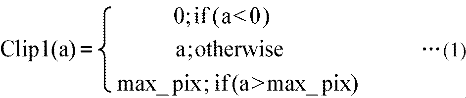
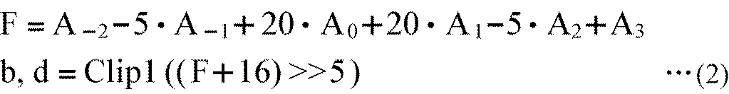


ブロックCに関する動きベクトル情報が、画枠の端であったり、あるいは、まだ符号化されていないなどの理由により、利用可能でない(unavailableである)場合がある。この場合には、ブロックCに関する動きベクトル情報は、ブロックDに関する動きベクトル情報で代用される。
mvdE = mvE - pmvE ・・・(6)
mvE = pmvE ・・・(7)

図7は、動き予測・補償部および動きベクトル精度判定部の詳細な構成例を示すブロック図である。なお、各詳細については、適宜、上述した図5の対象ブロックEおよび隣接ブロックA乃至Dを用いて説明する。
次に、図8のフローチャートを参照して、図1の画像符号化装置51の符号化処理について説明する。
次に、図9のフローチャートを参照して、図8のステップS21における予測処理を説明する。
次に、図10のフローチャートを参照して、図9のステップS31におけるイントラ予測処理を説明する。なお、図10の例においては、輝度信号の場合を例として説明する。
Dは、原画像と復号画像の差分(歪)、Rは、直交変換係数まで含んだ発生符号量、λは、量子化パラメータQPの関数として与えられるラグランジュ乗数である。
Dは、原画像と復号画像の差分(歪)、Header_Bitは、予測モードに対するヘッダビット、QPtoQuantは、量子化パラメータQPの関数として与えられる関数である。
次に、図11のフローチャートを参照して、図9のステップS32のインター動き予測処理について説明する。
mvX = mvX*2 ・・・(11)
mvX = mvX/2 ・・・(12)
次に、図12のフローチャートを参照して、図11のステップS53の動きベクトル精度判定処理について説明する。
図13は、を適用した画像処理装置としての画像復号装置の一実施の形態の構成を表している。
図14は、動き予測・補償部および動きベクトル精度判定部の詳細な構成例を示すブロック図である。なお、各詳細については、適宜、上述した図5の対象ブロックEおよび隣接ブロックA乃至Dを用いて説明する。
次に、図15のフローチャートを参照して、画像復号装置101が実行する復号処理について説明する。
次に、図16のフローチャートを参照して、図15のステップS138の予測処理を説明する。
Claims (12)
- 対象ブロックの動きベクトル情報の精度と、前記対象ブロックに隣接する隣接ブロックの動きベクトル情報の精度とが同じであるか異なるかを示す精度フラグを生成する精度フラグ生成手段と、
前記対象ブロックの動きベクトル情報と、前記精度フラグ生成手段により生成された前記精度フラグを符号化する符号化手段と
を備える画像処理装置。 - 前記精度フラグ生成手段により生成された前記精度フラグが、前記対象ブロックの動きベクトル情報の精度と、前記隣接ブロックの動きベクトル情報の精度とが異なることを示す場合、前記隣接ブロックの動きベクトル情報の精度を、前記対象ブロックの動きベクトル情報の精度に換算してメディアン予測を行い、予測動きベクトル情報を生成する予測動きベクトル生成手段をさらに備え、
前記符号化手段は、前記対象ブロックの動きベクトル情報として、前記対象ブロックの動きベクトル情報と前記予測動きベクトル情報との差分を符号化する
請求項1に記載の画像処理装置。 - 前記精度フラグ生成手段および前記予測動きベクトル生成手段は、前記隣接ブロックとして、前記対象ブロックの左部に隣接するブロックを用いる
請求項2に記載の画像処理装置。 - 前記精度フラグ生成手段および前記予測動きベクトル生成手段は、前記隣接ブロックとして、前記対象ブロックに隣接するとともに、直前に符号化処理が施されたブロックを用いる
請求項2に記載の画像処理装置。 - 前記精度フラグ生成手段および前記予測動きベクトル生成手段は、前記隣接ブロックとして、前記対象ブロック隣接するとともに、メディアン予測により選択された動きベクトル情報を与えるブロックを用いる
請求項2に記載の画像処理装置。 - 画像処理装置が、
対象ブロックの動きベクトル情報の精度と、前記対象ブロックに隣接する隣接ブロックの動きベクトル情報の精度とが同じであるか異なるかを示す精度フラグを生成し、
前記対象ブロックの動きベクトル情報と、生成された前記精度フラグを符号化するステップを
含む画像処理方法。 - 符号化された対象ブロックの動きベクトル情報、および前記対象ブロックの動きベクトル情報の精度と、前記対象ブロックに隣接する隣接ブロックの動きベクトル情報の精度とが同じであるか異なるかを示す精度フラグを復号する復号手段と、
前記復号手段により復号された前記精度フラグを用いて、前記復号手段により復号された前記対象ブロックの動きベクトル情報を再構成する動きベクトル再構成手段と、
前記動きベクトル再構成手段により再構成された前記対象ブロックの動きベクトル情報を用いて、前記対象ブロックの予測画像を生成する予測画像生成手段と
を備える画像処理装置。 - 前記復号手段により復号された前記精度フラグが、前記対象ブロックの動きベクトル情報の精度と、前記隣接ブロックの動きベクトル情報の精度とが異なることを示す場合、前記隣接ブロックの動きベクトル情報の精度を、前記対象ブロックの動きベクトル情報の精度に換算してメディアン予測を行い、予測動きベクトル情報を生成する予測動きベクトル生成手段をさらに備え、
前記動きベクトル再構成手段は、前記復号手段により復号された前記精度フラグと、前記予測動きベクトル生成手段により生成された前記予測動きベクトル情報を用いて、前記復号手段により復号された前記対象ブロックの動きベクトル情報を再構成する
請求項7に記載の画像処理装置。 - 前記動きベクトル再構成手段と前記予測動きベクトル生成手段は、前記隣接ブロックとして、前記対象ブロックの左部に隣接するブロックを用いる
請求項8に記載の画像処理装置。 - 前記動きベクトル再構成手段と前記予測動きベクトル生成手段は、前記隣接ブロックとして、前記対象ブロックに隣接するとともに、直前に符号化処理が施されたブロックを用いる
請求項8に記載の画像処理装置。 - 前記動きベクトル再構成手段と前記予測動きベクトル生成手段は、前記隣接ブロックとして、前記対象ブロック隣接するとともに、メディアン予測により選択された動きベクトル情報を与えるブロックを用いる
請求項8に記載の画像処理装置。 - 画像処理装置が、
符号化された対象ブロックの動きベクトル情報、および前記対象ブロックの動きベクトル情報の精度と、前記対象ブロックに隣接する隣接ブロックの動きベクトル情報の精度とが同じであるか異なるかを示す精度フラグを復号し、
復号された前記精度フラグを用いて、復号された前記対象ブロックの動きベクトル情報を再構成し、
再構成された前記対象ブロックの動きベクトル情報を用いて、前記対象ブロックの予測画像を生成するステップを
含む画像処理方法。
Priority Applications (9)
| Application Number | Priority Date | Filing Date | Title |
|---|---|---|---|
| CA2752736A CA2752736A1 (en) | 2009-03-06 | 2010-02-25 | Image processing device and method |
| CN201080010021.1A CN102342108B (zh) | 2009-03-06 | 2010-02-25 | 图像处理设备和方法 |
| EP10748659A EP2405659A4 (en) | 2009-03-06 | 2010-02-25 | IMAGE PROCESSING DEVICE AND METHOD |
| JP2011502727A JPWO2010101064A1 (ja) | 2009-03-06 | 2010-02-25 | 画像処理装置および方法 |
| BRPI1009535A BRPI1009535A2 (pt) | 2009-03-06 | 2010-02-25 | dispositivo e método de processamento de imagem. |
| RU2011136072/07A RU2011136072A (ru) | 2009-03-06 | 2010-02-25 | Способ и устройство обработки изображения |
| US13/203,957 US20120057632A1 (en) | 2009-03-06 | 2010-02-25 | Image processing device and method |
| AU2010219746A AU2010219746A1 (en) | 2009-03-06 | 2010-02-25 | Image processing device and method |
| MX2011009117A MX2011009117A (es) | 2009-03-06 | 2010-02-25 | Dispositivo y meodo para procesamiento de imagenes. |
Applications Claiming Priority (2)
| Application Number | Priority Date | Filing Date | Title |
|---|---|---|---|
| JP2009054077 | 2009-03-06 | ||
| JP2009-054077 | 2009-03-06 |
Publications (1)
| Publication Number | Publication Date |
|---|---|
| WO2010101064A1 true WO2010101064A1 (ja) | 2010-09-10 |
Family
ID=42709623
Family Applications (1)
| Application Number | Title | Priority Date | Filing Date |
|---|---|---|---|
| PCT/JP2010/052925 WO2010101064A1 (ja) | 2009-03-06 | 2010-02-25 | 画像処理装置および方法 |
Country Status (12)
| Country | Link |
|---|---|
| US (1) | US20120057632A1 (ja) |
| EP (1) | EP2405659A4 (ja) |
| JP (1) | JPWO2010101064A1 (ja) |
| KR (1) | KR20110139684A (ja) |
| CN (1) | CN102342108B (ja) |
| AU (1) | AU2010219746A1 (ja) |
| BR (1) | BRPI1009535A2 (ja) |
| CA (1) | CA2752736A1 (ja) |
| MX (1) | MX2011009117A (ja) |
| RU (1) | RU2011136072A (ja) |
| TW (1) | TW201041404A (ja) |
| WO (1) | WO2010101064A1 (ja) |
Cited By (3)
| Publication number | Priority date | Publication date | Assignee | Title |
|---|---|---|---|---|
| JP2013543713A (ja) * | 2010-10-13 | 2013-12-05 | クゥアルコム・インコーポレイテッド | ビデオ符号化のための適応動きベクトル解像度信号伝達 |
| US9237355B2 (en) | 2010-02-19 | 2016-01-12 | Qualcomm Incorporated | Adaptive motion resolution for video coding |
| JP2016519674A (ja) * | 2013-03-20 | 2016-07-07 | バイエル・ファルマ・アクティエンゲゼルシャフト | 過剰増殖障害を治療または予防するための3−アセチルアミノ−1−(フェニル−ヘテロアリール−アミノカルボニルまたはフェニル−ヘテロアリール−カルボニルアミノ)ベンゼン誘導体 |
Families Citing this family (14)
| Publication number | Priority date | Publication date | Assignee | Title |
|---|---|---|---|---|
| KR101675707B1 (ko) * | 2011-06-23 | 2016-11-11 | 가부시키가이샤 제이브이씨 켄우드 | 화상 인코딩 장치, 화상 인코딩 방법 및 화상 인코딩 프로그램, 및 화상 디코딩 장치, 화상 디코딩 방법 및 화상 디코딩 프로그램 |
| CN104584414B (zh) * | 2012-08-28 | 2016-10-26 | Abb技术有限公司 | 控制两级的模块化转换器 |
| CN109413425B (zh) * | 2012-09-03 | 2023-04-14 | 索尼公司 | 图像处理设备和方法 |
| US9706229B2 (en) * | 2013-06-05 | 2017-07-11 | Texas Instruments Incorporated | High definition VP8 decoder |
| CN115002458A (zh) * | 2015-06-05 | 2022-09-02 | 杜比实验室特许公司 | 图像编码和解码方法和图像解码设备 |
| US11272207B2 (en) | 2017-06-12 | 2022-03-08 | Futurewei Technologies, Inc. | Selection and signaling of motion vector (MV) precisions |
| US11303920B2 (en) | 2017-07-07 | 2022-04-12 | Samsung Electronics Co., Ltd. | Apparatus and method for encoding motion vector determined using adaptive motion vector resolution, and apparatus and method for decoding motion vector |
| KR102577754B1 (ko) * | 2017-09-28 | 2023-09-12 | 삼성전자주식회사 | 부호화 방법 및 그 장치, 복호화 방법 및 그 장치 |
| CN109905714B (zh) * | 2017-12-08 | 2022-12-27 | 华为技术有限公司 | 帧间预测方法、装置及终端设备 |
| KR20210016054A (ko) * | 2018-06-30 | 2021-02-10 | 김기백 | 영상 부호화/복호화 방법 및 장치 |
| WO2020084473A1 (en) | 2018-10-22 | 2020-04-30 | Beijing Bytedance Network Technology Co., Ltd. | Multi- iteration motion vector refinement |
| KR20240007302A (ko) * | 2018-11-12 | 2024-01-16 | 베이징 바이트댄스 네트워크 테크놀로지 컴퍼니, 리미티드 | 인터 및 인트라 통합 예측의 단순화 |
| WO2020103852A1 (en) | 2018-11-20 | 2020-05-28 | Beijing Bytedance Network Technology Co., Ltd. | Difference calculation based on patial position |
| CN113545065B (zh) | 2019-03-06 | 2023-12-12 | 北京字节跳动网络技术有限公司 | 转换后的单向预测候选的使用 |
Citations (2)
| Publication number | Priority date | Publication date | Assignee | Title |
|---|---|---|---|---|
| JPH09121359A (ja) * | 1995-10-26 | 1997-05-06 | Hitachi Ltd | 画像符号化方法および画像復号化方法 |
| JP2006187025A (ja) * | 2002-01-24 | 2006-07-13 | Hitachi Ltd | 動画像信号の符号化方法、復号化方法、符号化装置及び復号化装置 |
Family Cites Families (9)
| Publication number | Priority date | Publication date | Assignee | Title |
|---|---|---|---|---|
| KR100359115B1 (ko) * | 2000-05-24 | 2002-11-04 | 삼성전자 주식회사 | 영상 코딩 방법 |
| WO2003063503A1 (en) * | 2002-01-24 | 2003-07-31 | Hitachi, Ltd. | Moving picture signal coding method, decoding method, coding apparatus, and decoding apparatus |
| US6728315B2 (en) * | 2002-07-24 | 2004-04-27 | Apple Computer, Inc. | Method and apparatus for variable accuracy inter-picture timing specification for digital video encoding with reduced requirements for division operations |
| US7499495B2 (en) * | 2003-07-18 | 2009-03-03 | Microsoft Corporation | Extended range motion vectors |
| TWI253001B (en) * | 2004-11-16 | 2006-04-11 | An Lnternet Products & Technol | Method for setting the threshold of a fast motion estimation algorithm |
| JP2006238291A (ja) * | 2005-02-28 | 2006-09-07 | Ricoh Printing Systems Ltd | カラー画像情報の符号化処理方法、復号化処理方法およびこれを用いた印刷装置 |
| JP4713972B2 (ja) * | 2005-07-27 | 2011-06-29 | 株式会社東芝 | 符号化装置 |
| JP4235209B2 (ja) * | 2006-02-10 | 2009-03-11 | Nttエレクトロニクス株式会社 | 動きベクトル検出装置および動きベクトル検出方法 |
| CN101102503A (zh) * | 2006-07-07 | 2008-01-09 | 华为技术有限公司 | 视频分层编码层间运动矢量的预测方法 |
-
2010
- 2010-02-03 TW TW099103245A patent/TW201041404A/zh unknown
- 2010-02-25 CA CA2752736A patent/CA2752736A1/en not_active Abandoned
- 2010-02-25 KR KR1020117020036A patent/KR20110139684A/ko not_active Application Discontinuation
- 2010-02-25 JP JP2011502727A patent/JPWO2010101064A1/ja active Pending
- 2010-02-25 RU RU2011136072/07A patent/RU2011136072A/ru unknown
- 2010-02-25 WO PCT/JP2010/052925 patent/WO2010101064A1/ja active Application Filing
- 2010-02-25 EP EP10748659A patent/EP2405659A4/en not_active Withdrawn
- 2010-02-25 AU AU2010219746A patent/AU2010219746A1/en not_active Abandoned
- 2010-02-25 CN CN201080010021.1A patent/CN102342108B/zh not_active Expired - Fee Related
- 2010-02-25 MX MX2011009117A patent/MX2011009117A/es not_active Application Discontinuation
- 2010-02-25 US US13/203,957 patent/US20120057632A1/en not_active Abandoned
- 2010-02-25 BR BRPI1009535A patent/BRPI1009535A2/pt not_active IP Right Cessation
Patent Citations (2)
| Publication number | Priority date | Publication date | Assignee | Title |
|---|---|---|---|---|
| JPH09121359A (ja) * | 1995-10-26 | 1997-05-06 | Hitachi Ltd | 画像符号化方法および画像復号化方法 |
| JP2006187025A (ja) * | 2002-01-24 | 2006-07-13 | Hitachi Ltd | 動画像信号の符号化方法、復号化方法、符号化装置及び復号化装置 |
Non-Patent Citations (3)
| Title |
|---|
| "Motion compensated prediction with 1/8-pel displacement vector resolution", VCEG-AD09, ITU-TELECOMMUNICATIONS STANDARDIZATION SECTOR STUDY GROUP QUESTION 6 VIDEO CODING EXPERTS GROUP (VCEG, 27 October 2006 (2006-10-27) |
| "Video Coding Using Extended Block Sizes", VCEG-AD09, ITU-TELECOMMUNICATIONS STANDARDIZATION SECTOR STUDY GROUP QUESTION 16 - CONTRIBUTION 123, January 2009 (2009-01-01) |
| See also references of EP2405659A4 |
Cited By (4)
| Publication number | Priority date | Publication date | Assignee | Title |
|---|---|---|---|---|
| US9237355B2 (en) | 2010-02-19 | 2016-01-12 | Qualcomm Incorporated | Adaptive motion resolution for video coding |
| JP2013543713A (ja) * | 2010-10-13 | 2013-12-05 | クゥアルコム・インコーポレイテッド | ビデオ符号化のための適応動きベクトル解像度信号伝達 |
| US10327008B2 (en) | 2010-10-13 | 2019-06-18 | Qualcomm Incorporated | Adaptive motion vector resolution signaling for video coding |
| JP2016519674A (ja) * | 2013-03-20 | 2016-07-07 | バイエル・ファルマ・アクティエンゲゼルシャフト | 過剰増殖障害を治療または予防するための3−アセチルアミノ−1−(フェニル−ヘテロアリール−アミノカルボニルまたはフェニル−ヘテロアリール−カルボニルアミノ)ベンゼン誘導体 |
Also Published As
| Publication number | Publication date |
|---|---|
| BRPI1009535A2 (pt) | 2016-03-15 |
| US20120057632A1 (en) | 2012-03-08 |
| RU2011136072A (ru) | 2013-03-10 |
| MX2011009117A (es) | 2011-10-06 |
| EP2405659A1 (en) | 2012-01-11 |
| EP2405659A4 (en) | 2013-01-02 |
| KR20110139684A (ko) | 2011-12-29 |
| CN102342108B (zh) | 2014-07-09 |
| CA2752736A1 (en) | 2010-09-10 |
| AU2010219746A1 (en) | 2011-09-08 |
| TW201041404A (en) | 2010-11-16 |
| CN102342108A (zh) | 2012-02-01 |
| JPWO2010101064A1 (ja) | 2012-09-10 |
Similar Documents
| Publication | Publication Date | Title |
|---|---|---|
| JP5234368B2 (ja) | 画像処理装置および方法 | |
| WO2010101064A1 (ja) | 画像処理装置および方法 | |
| JP6057140B2 (ja) | 画像処理装置および方法、プログラム、並びに、記録媒体 | |
| JP5597968B2 (ja) | 画像処理装置および方法、プログラム、並びに記録媒体 | |
| WO2010095559A1 (ja) | 画像処理装置および方法 | |
| WO2011024685A1 (ja) | 画像処理装置および方法 | |
| WO2010095560A1 (ja) | 画像処理装置および方法 | |
| WO2010035731A1 (ja) | 画像処理装置および方法 | |
| WO2010035734A1 (ja) | 画像処理装置および方法 | |
| WO2010035730A1 (ja) | 画像処理装置および方法 | |
| WO2011089973A1 (ja) | 画像処理装置および方法 | |
| JP2011041037A (ja) | 画像処理装置および方法 | |
| WO2011086964A1 (ja) | 画像処理装置および方法、並びにプログラム | |
| WO2010035732A1 (ja) | 画像処理装置および方法 | |
| WO2011152315A1 (ja) | 画像処理装置および方法 | |
| JPWO2010064674A1 (ja) | 画像処理装置および画像処理方法、並びにプログラム | |
| WO2011086963A1 (ja) | 画像処理装置および方法 | |
| JP2013098899A (ja) | 符号化装置および符号化方法、並びに、復号装置および復号方法 | |
| WO2010035735A1 (ja) | 画像処理装置および方法 | |
| JP2014143716A (ja) | 画像処理装置および方法、プログラム、並びに記録媒体 | |
| JP2012019447A (ja) | 画像処理装置および方法 | |
| WO2011125625A1 (ja) | 画像処理装置および方法 | |
| JP6268556B2 (ja) | 画像処理装置および方法、プログラム、並びに、記録媒体 | |
| JP2014225910A (ja) | 画像処理装置および方法 | |
| WO2012077530A1 (ja) | 画像処理装置および方法 |
Legal Events
| Date | Code | Title | Description |
|---|---|---|---|
| WWE | Wipo information: entry into national phase |
Ref document number: 201080010021.1 Country of ref document: CN |
|
| 121 | Ep: the epo has been informed by wipo that ep was designated in this application |
Ref document number: 10748659 Country of ref document: EP Kind code of ref document: A1 |
|
| WWE | Wipo information: entry into national phase |
Ref document number: 2752736 Country of ref document: CA |
|
| WWE | Wipo information: entry into national phase |
Ref document number: 2010748659 Country of ref document: EP |
|
| WWE | Wipo information: entry into national phase |
Ref document number: 2010219746 Country of ref document: AU |
|
| ENP | Entry into the national phase |
Ref document number: 20117020036 Country of ref document: KR Kind code of ref document: A |
|
| WWE | Wipo information: entry into national phase |
Ref document number: 2011136072 Country of ref document: RU Ref document number: 6620/DELNP/2011 Country of ref document: IN |
|
| WWE | Wipo information: entry into national phase |
Ref document number: 2011502727 Country of ref document: JP Ref document number: MX/A/2011/009117 Country of ref document: MX |
|
| NENP | Non-entry into the national phase |
Ref country code: DE |
|
| ENP | Entry into the national phase |
Ref document number: 2010219746 Country of ref document: AU Date of ref document: 20100225 Kind code of ref document: A |
|
| WWE | Wipo information: entry into national phase |
Ref document number: 13203957 Country of ref document: US |
|
| REG | Reference to national code |
Ref country code: BR Ref legal event code: B01A Ref document number: PI1009535 Country of ref document: BR |
|
| ENP | Entry into the national phase |
Ref document number: PI1009535 Country of ref document: BR Kind code of ref document: A2 Effective date: 20110830 |