WO2010100965A1 - Device for controlling temperature of catalyst - Google Patents
Device for controlling temperature of catalyst Download PDFInfo
- Publication number
- WO2010100965A1 WO2010100965A1 PCT/JP2010/050564 JP2010050564W WO2010100965A1 WO 2010100965 A1 WO2010100965 A1 WO 2010100965A1 JP 2010050564 W JP2010050564 W JP 2010050564W WO 2010100965 A1 WO2010100965 A1 WO 2010100965A1
- Authority
- WO
- WIPO (PCT)
- Prior art keywords
- combustion
- target
- exhaust gas
- fuel supply
- catalyst
- Prior art date
Links
Images


Classifications
-
- F—MECHANICAL ENGINEERING; LIGHTING; HEATING; WEAPONS; BLASTING
- F02—COMBUSTION ENGINES; HOT-GAS OR COMBUSTION-PRODUCT ENGINE PLANTS
- F02D—CONTROLLING COMBUSTION ENGINES
- F02D41/00—Electrical control of supply of combustible mixture or its constituents
- F02D41/02—Circuit arrangements for generating control signals
- F02D41/021—Introducing corrections for particular conditions exterior to the engine
- F02D41/0235—Introducing corrections for particular conditions exterior to the engine in relation with the state of the exhaust gas treating apparatus
- F02D41/024—Introducing corrections for particular conditions exterior to the engine in relation with the state of the exhaust gas treating apparatus to increase temperature of the exhaust gas treating apparatus
-
- F—MECHANICAL ENGINEERING; LIGHTING; HEATING; WEAPONS; BLASTING
- F02—COMBUSTION ENGINES; HOT-GAS OR COMBUSTION-PRODUCT ENGINE PLANTS
- F02D—CONTROLLING COMBUSTION ENGINES
- F02D35/00—Controlling engines, dependent on conditions exterior or interior to engines, not otherwise provided for
- F02D35/02—Controlling engines, dependent on conditions exterior or interior to engines, not otherwise provided for on interior conditions
- F02D35/028—Controlling engines, dependent on conditions exterior or interior to engines, not otherwise provided for on interior conditions by determining the combustion timing or phasing
-
- F—MECHANICAL ENGINEERING; LIGHTING; HEATING; WEAPONS; BLASTING
- F02—COMBUSTION ENGINES; HOT-GAS OR COMBUSTION-PRODUCT ENGINE PLANTS
- F02D—CONTROLLING COMBUSTION ENGINES
- F02D41/00—Electrical control of supply of combustible mixture or its constituents
- F02D41/30—Controlling fuel injection
- F02D41/38—Controlling fuel injection of the high pressure type
- F02D41/40—Controlling fuel injection of the high pressure type with means for controlling injection timing or duration
- F02D41/402—Multiple injections
-
- Y—GENERAL TAGGING OF NEW TECHNOLOGICAL DEVELOPMENTS; GENERAL TAGGING OF CROSS-SECTIONAL TECHNOLOGIES SPANNING OVER SEVERAL SECTIONS OF THE IPC; TECHNICAL SUBJECTS COVERED BY FORMER USPC CROSS-REFERENCE ART COLLECTIONS [XRACs] AND DIGESTS
- Y02—TECHNOLOGIES OR APPLICATIONS FOR MITIGATION OR ADAPTATION AGAINST CLIMATE CHANGE
- Y02T—CLIMATE CHANGE MITIGATION TECHNOLOGIES RELATED TO TRANSPORTATION
- Y02T10/00—Road transport of goods or passengers
- Y02T10/10—Internal combustion engine [ICE] based vehicles
- Y02T10/12—Improving ICE efficiencies
-
- Y—GENERAL TAGGING OF NEW TECHNOLOGICAL DEVELOPMENTS; GENERAL TAGGING OF CROSS-SECTIONAL TECHNOLOGIES SPANNING OVER SEVERAL SECTIONS OF THE IPC; TECHNICAL SUBJECTS COVERED BY FORMER USPC CROSS-REFERENCE ART COLLECTIONS [XRACs] AND DIGESTS
- Y02—TECHNOLOGIES OR APPLICATIONS FOR MITIGATION OR ADAPTATION AGAINST CLIMATE CHANGE
- Y02T—CLIMATE CHANGE MITIGATION TECHNOLOGIES RELATED TO TRANSPORTATION
- Y02T10/00—Road transport of goods or passengers
- Y02T10/10—Internal combustion engine [ICE] based vehicles
- Y02T10/40—Engine management systems
Abstract
Provided is a device for controlling the temperature of a catalyst, wherein the exhaust gas characteristics can be satisfactorily maintained, and the catalyst can be rapidly activated. In a temperature control device (1) for a catalyst (10), fuel is supplied to an internal combustion engine (3) in several batches. Further, the operation states (TCAT, PMCMD, NE, QA, TA, PB, QEGR, PF) of the internal combustion engine (3) are detected, and a plurality of fuel supply timings (TINJ1 to TINJ5) by which the fuel is supplied by a fuel supply means in several batches, are set in accordance with the detected operation state of the internal combustion engine (3).
Description
本発明は、内燃機関から排出された排ガスを浄化する触媒の温度を制御する触媒の温度制御装置に関する。
The present invention relates to a catalyst temperature control device that controls the temperature of a catalyst that purifies exhaust gas discharged from an internal combustion engine.
従来のこの種の温度制御装置として、例えば特許文献1に開示されたものが知られている。この温度制御装置では、触媒が活性状態にないときに、内燃機関への燃料の供給を3回に分割して行い、それにより、排ガスの温度を高めることによって、触媒の温度を上昇させる。このときの燃料の供給タイミングは、1回目と2回目の間の燃料供給の間隔と、2回目と3回目の燃料供給の間隔が、互いに同じ一定の間隔になるように設定される。
As a conventional temperature control device of this type, for example, one disclosed in Patent Document 1 is known. In this temperature control device, when the catalyst is not activated, the fuel supply to the internal combustion engine is divided into three times, thereby raising the temperature of the catalyst by raising the temperature of the exhaust gas. The fuel supply timing at this time is set so that the interval of fuel supply between the first and second times and the interval of fuel supply between the second and third times become the same constant interval.
一般に、同一の運転ポイントにおいて排ガスの温度が高くなるような燃焼が行われると、排ガスの温度が高くなるほど、排ガスに含まれる未燃燃料が多くなり、燃料消費量も多くなる。また、触媒が活性状態にないときには、触媒で反応することなく触媒を通過する未燃燃料の量は多くなる。これに対して、従来の温度制御装置では、燃料供給を一定の等間隔で行うにすぎないため、内燃機関の運転状態によっては、複数回の燃焼期間に対応する複数の燃焼期間の間で燃焼の開始タイミングがばらつくことがある。その場合には、複数の燃焼期間の全体において燃焼状態が変動するため、排ガスの温度を精度良く制御することができない。例えば、排ガスの温度が低すぎる場合には、触媒の温度を速やかに上昇させることができないため、触媒を速やかに活性化することができず、排ガス特性が悪化し、排ガスの温度が高すぎる場合には、上述したように排ガス中の未燃燃料が多くなるため、やはり排ガス特性が悪化する。
In general, when combustion is performed such that the temperature of the exhaust gas becomes high at the same operation point, the higher the temperature of the exhaust gas, the more unburned fuel contained in the exhaust gas, and the more the fuel consumption. Also, when the catalyst is not active, the amount of unburned fuel passing through the catalyst without reacting with the catalyst will be large. On the other hand, in the conventional temperature control device, the fuel supply is performed only at a constant interval, and therefore, depending on the operating state of the internal combustion engine, combustion is performed between a plurality of combustion periods corresponding to a plurality of combustion periods. The start timing of may vary. In that case, since the combustion state fluctuates in the whole of a plurality of combustion periods, the temperature of the exhaust gas can not be accurately controlled. For example, when the temperature of the exhaust gas is too low, the temperature of the catalyst can not be raised promptly, so that the catalyst can not be activated quickly, and the exhaust gas characteristics deteriorate, and the temperature of the exhaust gas is too high. As described above, since the amount of unburned fuel in the exhaust gas increases, the exhaust gas characteristics also deteriorate.
本発明は、このような課題を解決するためになされたものであり、排ガス特性を良好に保てるとともに、触媒を速やかに活性化することができる触媒の温度制御装置を提供することを目的とする。
The present invention has been made to solve such problems, and it is an object of the present invention to provide a catalyst temperature control device capable of maintaining the exhaust gas characteristics well and rapidly activating the catalyst. .
上記の目的を達成するため、本願の請求項1に係る発明は、内燃機関3から排出された排ガスを浄化する触媒10の温度を制御する触媒10の温度制御装置1であって、内燃機関3に燃料を複数回に分割して供給する燃料供給手段(実施形態における(以下、本項において同じ)インジェクタ4、ECU2)と、内燃機関3の運転状態を検出する運転状態検出手段(クランク角センサ26、エアフローセンサ22、吸気温センサ23、吸気圧センサ24、EGR量センサ25、ECU2)と、検出された内燃機関3の運転状態(触媒温度TCAT、要求トルクPMCMD、エンジン回転数NE、吸入空気量QA、吸気温TA、吸気圧PB、EGR量QEGR、燃圧PF、燃料の性状、エンジン3の暖機状態やグロープラグ11の通電状態)に応じて、燃料供給手段により燃料を分割してそれぞれ供給する複数の燃料供給タイミング(第1~第5燃料噴射時期TINJ1~TINJ5)を設定する燃料供給タイミング設定手段(ECU2)と、を備えることを特徴とする。
In order to achieve the above object, the invention according to claim 1 of the present invention is a temperature control device 1 of a catalyst 10 for controlling the temperature of a catalyst 10 for purifying an exhaust gas discharged from an internal combustion engine 3. The fuel supply means (fuel supply means (in the embodiment, hereinafter the same in the present paragraph) injector 4 and ECU 2) for dividing the fuel into multiple times and detecting the operating state of the internal combustion engine 3 (crank angle sensor 26, the air flow sensor 22, the intake air temperature sensor 23, the intake pressure sensor 24, the EGR amount sensor 25, the ECU 2), and the detected operating state of the internal combustion engine 3 (catalyst temperature TCAT, required torque PMCMD, engine speed NE, intake air Amount QA, intake temperature TA, intake pressure PB, EGR amount QEGR, fuel pressure PF, fuel properties, warm-up state of the engine 3 and energization state of the glow plug 11) Accordingly, fuel supply timing setting means (ECU 2) for setting a plurality of fuel supply timings (first to fifth fuel injection timings TINJ1 to TINJ5) for dividing and supplying fuel separately by the fuel supply means; It features.
この触媒の温度制御装置によれば、燃料供給手段により、内燃機関への燃料の供給が複数回に分割して行われる。これにより、例えば、触媒が活性状態にないときには、排ガスの温度が高められ、触媒の温度が上昇する。また、これらの複数の燃料供給タイミングは、検出された内燃機関の運転状態に応じて設定される。
According to the catalyst temperature control device, the fuel supply means divides the fuel supply to the internal combustion engine a plurality of times. Thus, for example, when the catalyst is not in an activated state, the temperature of the exhaust gas is increased, and the temperature of the catalyst is increased. The plurality of fuel supply timings are set in accordance with the detected operating state of the internal combustion engine.
前述したように、排ガスに含まれる未燃燃料は、排ガスの温度に応じて変化する。また、複数回の燃料供給に対応する複数の燃焼期間においてそれぞれ燃焼が開始するタイミングは、燃料の供給タイミングに依存する。さらに、燃料の供給タイミングと燃焼の開始タイミングの関係は、内燃機関の運転状態に応じて変化する。したがって、検出された内燃機関の運転状態に応じて複数の燃料供給タイミングを設定することによって、各燃焼開始タイミングを内燃機関の運転状態に応じた適切なタイミングに制御することができる。これにより、複数の燃焼期間の全体にわたって安定した燃焼状態を確保でき、排ガスの温度、ひいては触媒の温度を適切に制御することができる。その結果、触媒が活性状態にないときには、大気中に排出される未燃燃料の量を低減でき、排ガス特性を良好に保ちながら、触媒を速やかに活性化することができる。一方、触媒が活性状態にあるときには、触媒の温度および浄化能力を適切に維持しながら、排ガスの温度をできる限り低い温度に維持するため、大気中への未燃燃料の排出量を最大限、低減でき、それにより、排ガス特性を良好に保つことができる。また、排ガスの温度の不必要な上昇を回避できる分、消費燃料量を低減することができる。
As described above, the unburned fuel contained in the exhaust gas changes in accordance with the temperature of the exhaust gas. Further, the timing at which combustion starts in a plurality of combustion periods corresponding to a plurality of fuel supplies depends on the fuel supply timing. Furthermore, the relationship between the fuel supply timing and the combustion start timing changes according to the operating state of the internal combustion engine. Therefore, each combustion start timing can be controlled to an appropriate timing according to the operating state of the internal combustion engine by setting the plurality of fuel supply timings in accordance with the detected operating state of the internal combustion engine. As a result, a stable combustion state can be maintained throughout the plurality of combustion periods, and the temperature of the exhaust gas and hence the temperature of the catalyst can be appropriately controlled. As a result, when the catalyst is not activated, the amount of unburned fuel discharged to the atmosphere can be reduced, and the catalyst can be rapidly activated while maintaining good exhaust gas characteristics. On the other hand, when the catalyst is in an active state, the emission of unburned fuel to the atmosphere is maximized to maintain the temperature of the exhaust gas as low as possible while maintaining the temperature and purification capacity of the catalyst appropriately. It is possible to reduce the exhaust gas characteristics. In addition, the amount of fuel consumption can be reduced as much as unnecessary increase in the temperature of the exhaust gas can be avoided.
請求項2に係る発明は、請求項1に記載の触媒10の温度制御装置1において、内燃機関3の運転状態に応じて、燃料供給手段による複数回の燃料供給に対応する複数の燃焼期間(第1~第5燃焼期間)においてそれぞれ燃焼が開始する燃焼開始タイミングの目標となる複数の目標燃焼開始タイミング(第1~第5目標燃焼時期TIG1~TIG5)を設定する目標燃焼開始タイミング設定手段(ECU2、図6のステップ42)と、内燃機関3の運転状態に応じて、複数回の燃料供給に対応する複数の燃焼の着火遅れ期間(第1~第5着火遅れ期間IGL1~IGL5)を算出する着火遅れ期間算出手段(ECU2)と、をさらに備え、燃料供給タイミング設定手段は、複数の目標燃焼開始タイミングから、対応する複数の着火遅れ期間をそれぞれ減算することによって、複数の燃料供給タイミングを設定することを特徴とする。
In the invention according to claim 2, in the temperature control device 1 for the catalyst 10 according to claim 1, according to the operating state of the internal combustion engine 3, a plurality of combustion periods corresponding to a plurality of fuel supplies by the fuel supply means ( Target combustion start timing setting means (a plurality of target combustion start timings (first to fifth target combustion timings TIG1 to TIG5) serving as targets of combustion start timings at which combustion starts in the first to fifth combustion periods) Based on the ECU 2 and step 42 of FIG. 6 and the operating state of the internal combustion engine 3, the ignition delay periods (first to fifth ignition delay periods IGL1 to IGL5) of the plurality of combustions corresponding to the fuel supply of a plurality of times are calculated. The fuel supply timing setting means further includes a plurality of ignition delay periods corresponding to the plurality of target combustion start timings. By subtracting respectively, and sets a plurality of fuel supply timing.
この構成によれば、内燃機関の運転状態に応じて、複数回の燃料供給に対応する複数の燃焼期間における複数の目標燃焼開始タイミングを設定し、内燃機関の運転状態に応じて、複数回の燃料供給に対応する複数の燃焼の着火遅れ期間を算出する。そして、複数の目標燃焼開始タイミングから、対応する複数の着火遅れ期間をそれぞれ減算することによって、複数の燃料供給タイミングを設定する。
According to this configuration, the plurality of target combustion start timings in the plurality of combustion periods corresponding to the plurality of fuel supplies are set according to the operation state of the internal combustion engine, and the plurality of target combustion start timings are performed according to the operation state of the internal combustion engine. A plurality of combustion ignition delay periods corresponding to the fuel supply are calculated. Then, a plurality of fuel supply timings are set by respectively subtracting a plurality of corresponding ignition delay periods from a plurality of target combustion start timings.
前述したように、燃料の供給タイミングと燃焼の開始タイミングの関係は、内燃機関の運転状態に応じて変化する。これは、燃焼の着火遅れ期間が内燃機関の運転状態に応じて変化するためである。したがって、上述したように、検出された内燃機関の運転状態に応じて、複数の目標燃焼開始タイミングを設定するとともに、複数の着火遅れ期間を算出し、両者を用いて複数の燃料供給タイミングを設定することによって、設定した適切な目標燃焼開始タイミングで実際の燃焼を開始させることができる。それにより、排ガスの温度、ひいては触媒の温度を適切に制御できる結果、排ガス特性をより良好に保てるとともに、触媒を速やかに活性化することができる。
As described above, the relationship between the fuel supply timing and the combustion start timing changes in accordance with the operating state of the internal combustion engine. This is because the ignition delay period of combustion changes according to the operating state of the internal combustion engine. Therefore, as described above, while setting a plurality of target combustion start timings according to the detected operation state of the internal combustion engine, a plurality of ignition delay periods are calculated, and a plurality of fuel supply timings are set using both of them. By doing this, actual combustion can be started at the set appropriate target combustion start timing. As a result, the temperature of the exhaust gas and hence the temperature of the catalyst can be properly controlled, so that the characteristics of the exhaust gas can be maintained better and the catalyst can be rapidly activated.
請求項3に係る発明は、内燃機関3から排出された排ガスを浄化する触媒10の温度を制御する触媒10の温度制御装置1であって、内燃機関3に燃料を複数回に分割して供給する燃料供給手段(インジェクタ4、ECU2)と、燃料供給手段による複数回の燃料供給に対応する複数の燃焼期間(第1~第5燃焼期間)においてそれぞれ燃焼が開始したタイミングを、複数の燃焼開始タイミング(第1~第5実燃焼時期IG1~IG5)として算出する燃焼開始タイミング算出手段(ECU2、図9~図11のステップ73,79,86,93,100)と、内燃機関3の運転状態を検出する運転状態検出手段(クランク角センサ26、アクセル開度センサ29、ECU2)と、検出された内燃機関3の運転状態(要求トルクPMCMD、目標排ガス温度TEMCMD)に応じて、複数の燃焼開始タイミングのそれぞれの目標となる複数の目標燃焼開始タイミング(第1~第5目標燃焼時期TIG1~TIG5)を設定する目標燃焼開始タイミング設定手段(ECU2、図6のステップ42)と、算出された複数の燃焼開始タイミングがそれぞれ複数の目標燃焼開始タイミングになるように、フィードバック制御により、燃料供給手段により燃料をそれぞれ供給するタイミングを、複数の燃料供給タイミング(第1~第5燃料噴射時期TINJ1~TINJ5)として設定する燃料供給タイミング設定手段(ECU2、図3のステップ7)と、を備えることを特徴とする。
The invention according to claim 3 is the temperature control device 1 of the catalyst 10 for controlling the temperature of the catalyst 10 for purifying the exhaust gas discharged from the internal combustion engine 3, and the fuel is divided and supplied to the internal combustion engine 3 multiple times. Timing at which combustion is started in a plurality of combustion periods (first to fifth combustion periods) corresponding to a plurality of fuel supplies by the fuel supply means (injector 4, ECU 2) and the fuel supply means The combustion start timing calculation means (ECU 2, steps 73, 79, 86, 93, 100 in FIGS. 9 to 11) calculated as the timing (first to fifth actual combustion timings IG1 to IG5) and the operating state of the internal combustion engine 3 Operating state detecting means (crank angle sensor 26, accelerator opening sensor 29, ECU 2) for detecting the operating state of the internal combustion engine 3 detected (required torque PMCMD, Target combustion start timing setting means (ECU 2) for setting a plurality of target combustion start timings (first to fifth target combustion timings TIG1 to TIG5) to be targets of the plurality of combustion start timings in accordance with the target exhaust gas temperature TEMCMD) 6, and the plurality of calculated combustion start timings respectively correspond to the plurality of target combustion start timings, the plurality of fuel supply timings are respectively supplied by the fuel supply unit by feedback control. And fuel supply timing setting means (ECU 2, step 7 in FIG. 3) set as timings (first to fifth fuel injection timings TINJ1 to TINJ5).
この触媒の温度制御装置によれば、燃料供給手段により、内燃機関への燃料の供給が複数回に分割して行われる。これにより、排ガスの温度を高め、触媒の温度を上昇させる。また、これらの複数回の燃料供給に対応する複数の燃焼期間においてそれぞれ燃焼が開始したタイミングを、複数の燃焼開始タイミングとして算出する。さらに、検出された内燃機関の運転状態に応じて、これらの燃焼開始タイミングのそれぞれの目標となる複数の目標燃焼開始タイミングを設定する。そして、複数の燃焼開始タイミングがそれぞれ、対応する目標燃焼開始タイミングになるように、フィードバック制御により、複数の燃料供給タイミングを設定する。
According to the catalyst temperature control device, the fuel supply means divides the fuel supply to the internal combustion engine a plurality of times. This raises the temperature of the exhaust gas and raises the temperature of the catalyst. Further, timings at which combustion has started in a plurality of combustion periods corresponding to a plurality of times of fuel supply are calculated as a plurality of combustion start timings. Furthermore, in accordance with the detected operating state of the internal combustion engine, a plurality of target combustion start timings that are targets of the respective combustion start timings are set. Then, a plurality of fuel supply timings are set by feedback control such that the plurality of combustion start timings respectively correspond to the corresponding target combustion start timings.
前述したように、排ガスに含まれる未燃燃料は、排ガスの温度に応じて変化する。これに対し、本発明によれば、上述したように、各燃焼期間において算出された実際の燃焼開始タイミングが、検出された内燃機関の運転状態に応じて設定された、対応する目標燃焼開始タイミングになるように、燃料供給タイミングを設定するので、各燃焼開始タイミングを内燃機関の運転状態に応じた適切なタイミングに制御できる。これにより、複数の燃焼期間の全体にわたって安定した燃焼状態を確保でき、排ガスの温度、ひいては触媒の温度を適切に制御することができる。その結果、触媒が活性状態にないときには、大気中に排出される未燃燃料の量を低減でき、排ガス特性を良好に保ちながら、触媒を速やかに活性化することができる。一方、触媒が活性状態にあるときには、触媒の温度および浄化能力を適切に維持しながら、排ガスの温度をできる限り低い温度に維持することができるため、大気中への未燃燃料の排出量を最大限、低減でき、それにより、排ガス特性を良好に保つことができる。また、排ガスの温度の不必要な上昇を回避できる分、消費燃料量を低減することができる。
As described above, the unburned fuel contained in the exhaust gas changes in accordance with the temperature of the exhaust gas. On the other hand, according to the present invention, as described above, the actual target combustion start timing calculated in each combustion period is set according to the detected operating state of the internal combustion engine. Since the fuel supply timing is set as follows, each combustion start timing can be controlled to an appropriate timing according to the operating state of the internal combustion engine. As a result, a stable combustion state can be maintained throughout the plurality of combustion periods, and the temperature of the exhaust gas and hence the temperature of the catalyst can be appropriately controlled. As a result, when the catalyst is not activated, the amount of unburned fuel discharged to the atmosphere can be reduced, and the catalyst can be rapidly activated while maintaining good exhaust gas characteristics. On the other hand, when the catalyst is in an active state, the temperature of the exhaust gas can be maintained as low as possible while appropriately maintaining the temperature and purification capacity of the catalyst, so the amount of unburned fuel discharged into the atmosphere can be reduced. It can be reduced to the maximum, whereby the exhaust gas characteristics can be kept good. In addition, the amount of fuel consumption can be reduced as much as unnecessary increase in the temperature of the exhaust gas can be avoided.
請求項4に係る発明は、請求項2または3に記載の触媒10の温度制御装置1において、目標燃焼開始タイミング設定手段は、複数の燃焼期間の間で燃焼が継続して行われるように複数の目標燃焼開始タイミングを設定することを特徴とする。
In the invention according to claim 4, in the temperature control device 1 for the catalyst 10 according to claim 2 or 3, the target combustion start timing setting means is plural so that combustion is continuously performed between a plurality of combustion periods. Setting a target combustion start timing of
この構成によれば、各目標燃焼開始タイミングは、複数の燃焼期間の間で燃焼が継続して行われるように設定される。このため、各燃焼開始タイミングが対応する目標燃焼開始タイミングになるように複数の燃料供給タイミングを設定することによって、複数の燃焼期間の全体にわたって燃焼を途切れることなく行わせることができる。これにより、より安定した燃焼状態を確保することができ、排ガス特性を良好に保てるとともに、触媒を速やかに活性化することができる。
According to this configuration, each target combustion start timing is set such that combustion is continuously performed between the plurality of combustion periods. Therefore, by setting the plurality of fuel supply timings so that each combustion start timing corresponds to the corresponding target combustion start timing, the combustion can be performed without interruption throughout the plurality of combustion periods. As a result, a more stable combustion state can be secured, and the exhaust gas characteristics can be well maintained, and the catalyst can be rapidly activated.
請求項5に係る発明は、請求項2ないし4のいずれかに記載の触媒10の温度制御装置1において、排ガスの温度の目標となる目標排ガス温度TEMCMDを設定する目標排ガス温度設定手段(ECU2、図4のステップ23,34)をさらに備え、目標燃焼開始タイミング設定手段は、設定された目標排ガス温度TEMCMDが高いほど、複数の燃焼期間の長さがより長くなるように複数の目標燃焼開始タイミングを設定することを特徴とする。
In the invention according to claim 5, in the temperature control device 1 for the catalyst 10 according to any one of claims 2 to 4, target exhaust gas temperature setting means (ECU 2, The method further includes the steps 23, 34) of FIG. 4, and the target combustion start timing setting means sets the plurality of target combustion start timings such that the lengths of the plurality of combustion periods become longer as the set target exhaust gas temperature TEMCMD becomes higher. To set.
この構成によれば、設定された目標排ガス温度が高いほど、各燃焼期間の長さがより長くなるように複数の目標燃焼開始タイミングを設定する。各燃焼期間の長さが長くなるほど、1燃焼サイクルにおいて燃焼が行われる全体の燃焼期間も長くなるため、排ガスの温度は高くなる。したがって、上述したように、目標排ガス温度が高いほど、各燃焼期間の長さがより長くなるように目標燃焼開始タイミングを設定することによって、排ガスの温度を触媒の温度に応じて適切に制御することができる。その結果、排ガス特性をより良好に保てるとともに、触媒を速やかに活性化することができる。
According to this configuration, the plurality of target combustion start timings are set such that the length of each combustion period becomes longer as the set target exhaust gas temperature is higher. As the length of each combustion period is longer, the temperature of the exhaust gas is higher because the entire combustion period in which combustion is performed in one combustion cycle is also longer. Therefore, as described above, by setting the target combustion start timing so that the length of each combustion period is longer as the target exhaust gas temperature is higher, the temperature of the exhaust gas is appropriately controlled according to the temperature of the catalyst. be able to. As a result, the exhaust gas characteristics can be maintained better, and the catalyst can be rapidly activated.
請求項6に係る発明は、請求項5に記載の触媒10の温度制御装置1において、燃料供給手段は、膨張行程の開始時付近から終了時までの所定の期間において、燃料供給を実行し、目標燃焼開始タイミング設定手段は、目標排ガス温度TEMCMDが高いほど、複数の目標燃焼開始タイミングをより遅角側に設定することを特徴とする。
In the invention according to claim 6, in the temperature control device 1 of the catalyst 10 according to claim 5, the fuel supply means executes the fuel supply in a predetermined period from the vicinity of the start of the expansion stroke to the end of the expansion stroke, The target combustion start timing setting means sets the plurality of target combustion start timings to be more retarded as the target exhaust gas temperature TEMCMD is higher.
この構成によれば、複数回の燃料供給は、膨張行程の開始時付近から終了時までの所定の期間において実行される。燃料供給を膨張行程で行う場合、排ガスの温度は、燃料供給タイミングが遅角側にあるほど、より高くなる。このような観点から、本発明によれば、目標排ガス温度が高いほど、複数の目標燃焼開始タイミングをより遅角側に設定するので、排ガスの温度を触媒の温度に応じて適切に制御でき、その結果、排ガス特性をより良好に保てるとともに、触媒を速やかに活性化することができる。
According to this configuration, the plurality of fuel supplies are performed in a predetermined period from the vicinity of the start of the expansion stroke to the end. When the fuel supply is performed in the expansion stroke, the temperature of the exhaust gas becomes higher as the fuel supply timing is more retarded. From this point of view, according to the present invention, as the target exhaust gas temperature is higher, the plurality of target combustion start timings are set to be more retarded, so the temperature of the exhaust gas can be appropriately controlled according to the temperature of the catalyst, As a result, the exhaust gas characteristics can be maintained better, and the catalyst can be rapidly activated.
請求項7に係る発明は、請求項3ないし6のいずれかに記載の触媒10の温度制御装置1において、内燃機関3の気筒3a内の圧力を筒内圧PCYLとして検出する筒内圧検出手段(筒内圧センサ21)と、検出された筒内圧PCYLに基づいて、熱発生率dQHRを算出する熱発生率算出手段(ECU2)と、をさらに備え、燃焼開始タイミング算出手段は、算出された熱発生率dQHRに基づいて、複数の燃焼開始タイミングを算出することを特徴とする。
In the invention according to claim 7, in the temperature control device 1 for the catalyst 10 according to any one of claims 3 to 6, the in-cylinder pressure detection means (cylinder) detects the pressure in the cylinder 3a of the internal combustion engine 3 as the in-cylinder pressure PCYL. The internal combustion pressure sensor 21) and heat release rate calculation means (ECU 2) for calculating the heat release rate dQHR based on the detected in-cylinder pressure PCYL, and the combustion start timing calculation means calculates the heat release rate calculated A plurality of combustion start timings are calculated based on dQHR.
この構成によれば、検出された筒内圧に基づいて、熱発生率が算出される。このようにして算出された熱発生率は、燃料の燃焼状態と高い相関性を有する。したがって、熱発生率に基づいて、複数の燃焼開始タイミングを適切に算出することができ、そのようにして算出した燃焼開始タイミングを用い、燃料供給タイミングを設定することにより、排ガスの温度を適切に制御でき、排ガス特性を良好に保てるとともに、触媒を速やかに活性化することができる。
According to this configuration, the heat release rate is calculated based on the detected in-cylinder pressure. The heat release rate calculated in this manner has a high correlation with the combustion state of the fuel. Therefore, based on the heat release rate, a plurality of combustion start timings can be appropriately calculated, and by setting the fuel supply timing using the combustion start timings calculated in this manner, the temperature of the exhaust gas can be appropriately set. The catalyst can be rapidly activated while being able to be controlled and maintaining the exhaust gas characteristics well.
請求項8に係る発明は、内燃機関3から排出された排ガスを浄化する触媒10の温度を制御する触媒10の温度制御装置1であって、内燃機関3に燃料を複数回に分割して供給する燃料供給手段(インジェクタ4、ECU2)と、内燃機関3の気筒3a内の圧力を筒内圧PCYLとして検出する筒内圧検出手段(筒内圧センサ21)と、検出された筒内圧PCYLに基づいて、熱発生率dQHRを算出する熱発生率算出手段(ECU2)と、算出された熱発生率dQHRの収束状態に応じて、燃料供給手段により燃料をそれぞれ供給するタイミングを、複数の燃料供給タイミングとして設定する燃料供給タイミング設定手段(ECU2)と、を備えることを特徴とする。
The invention according to claim 8 is the temperature control device 1 of the catalyst 10 for controlling the temperature of the catalyst 10 for purifying the exhaust gas discharged from the internal combustion engine 3, and the fuel is divided and supplied to the internal combustion engine 3 plural times. Fuel supply means (injector 4, ECU 2), in-cylinder pressure detection means (in-cylinder pressure sensor 21) for detecting the pressure in the cylinder 3a of the internal combustion engine 3 as the in-cylinder pressure PCYL, and According to the heat release rate calculation means (ECU 2) for calculating the heat release rate dQHR and the timing for supplying the fuel by the fuel supply means according to the convergence state of the calculated heat release rate dQHR, a plurality of fuel supply timings are set. And fuel supply timing setting means (ECU 2).
この触媒の温度制御装置によれば、燃料供給手段により、内燃機関への燃料の供給が複数回に分割して行われることによって、排ガスの温度を高め、触媒の温度を上昇させる。また、検出された筒内圧に基づいて算出された熱発生率の収束状態に応じて、複数の燃料供給タイミングを設定する。
According to the catalyst temperature control device, the fuel supply means divides the fuel supply to the internal combustion engine a plurality of times, thereby raising the temperature of the exhaust gas and raising the temperature of the catalyst. Also, a plurality of fuel supply timings are set according to the convergence state of the heat release rate calculated based on the detected in-cylinder pressure.
複数の燃焼期間の全体において燃焼状態が変動すると、排ガスの温度が変化する。また、燃料の燃焼の終期には、熱発生率は低下し、収束する。本発明によれば、熱発生率の収束状態に応じて、複数の燃料供給タイミングを設定するので、複数の燃焼期間の全体にわたって燃焼を途切れることなく行わせることができる。これにより、安定した燃焼状態を確保でき、排ガスの温度、ひいては触媒の温度を適切に制御することができる。その結果、触媒が活性状態にないときには、大気中に排出される未燃燃料の量を低減でき、排ガス特性を良好に保ちながら、触媒を速やかに活性化することができる。一方、触媒が活性状態にあるときには、触媒の温度および浄化能力を適切に維持しながら、排ガスの温度をできる限り低い温度に維持することができるため、大気中への未燃燃料の排出量を最大限、低減でき、それにより、排ガス特性を良好に保つことができる。また、排ガスの温度の不必要な上昇を回避できる分、消費燃料量を低減することができる。
Fluctuations in the combustion state throughout the plurality of combustion periods change the temperature of the exhaust gas. Also, at the end of fuel combustion, the heat release rate decreases and converges. According to the present invention, since the plurality of fuel supply timings are set according to the convergence state of the heat release rate, the combustion can be performed without interruption throughout the plurality of combustion periods. As a result, a stable combustion state can be secured, and the temperature of the exhaust gas, and hence the temperature of the catalyst, can be properly controlled. As a result, when the catalyst is not activated, the amount of unburned fuel discharged to the atmosphere can be reduced, and the catalyst can be rapidly activated while maintaining good exhaust gas characteristics. On the other hand, when the catalyst is in an active state, the temperature of the exhaust gas can be maintained as low as possible while appropriately maintaining the temperature and purification capacity of the catalyst, so the amount of unburned fuel discharged into the atmosphere can be reduced. It can be reduced to the maximum, whereby the exhaust gas characteristics can be kept good. In addition, the amount of fuel consumption can be reduced as much as unnecessary increase in the temperature of the exhaust gas can be avoided.
請求項9に係る発明は、請求項8に記載の触媒10の温度制御装置1において、排ガスの温度の目標となる目標排ガス温度TEMCMDを設定する目標排ガス温度設定手段(ECU2、図4のステップ23,24)をさらに備え、燃料供給タイミング設定手段は、設定された目標排ガス温度TEMCMDが高いほど、熱発生率dQHRの収束時期の前のより遅いタイミングで燃焼が開始するように、複数の燃料供給タイミングを設定することを特徴とする。
In the invention according to claim 9, in the temperature control device 1 for the catalyst 10 according to claim 8, target exhaust gas temperature setting means (ECU 2 for setting target exhaust gas temperature TEMCMD to be a target of exhaust gas temperature). , 24), and the fuel supply timing setting means supplies a plurality of fuels so that the higher the set target exhaust gas temperature TEMCMD, the later the combustion start timing before the convergence time of the heat release rate dQHR. It is characterized by setting a timing.
この構成によれば、設定された目標排ガス温度が高いほど、熱発生率の収束時期の前で、かつより遅いタイミングで燃焼が開始するように燃料供給を行う。燃焼の開始タイミングが遅くなるように燃料供給を行うと、1燃焼サイクルにおいて燃焼が行われる全体の燃焼期間も長くなるため、排ガスの温度は高くなる。したがって、上述したように、目標排ガス温度が高いほど、熱発生率の収束時期の前で、かつより遅いタイミングで燃焼が開始するように燃料供給を行うことによって、各燃焼期間を長く設定することができ、それにより、供給された燃料を確実に燃焼させることができる。その結果、未燃燃料の排出量を抑制しながら、複数の燃焼期間の全体にわたって途切れることなく、燃焼を確実に行うことができる。また、1燃焼サイクルにおける全体の燃焼期間が長くなることによって、排ガスの温度を、目標排ガス温度に応じて適切に高めることができるので、触媒の温度を適正に制御でき、その結果、排ガス特性をより良好に保てるとともに、触媒を速やかに活性化することができる。
According to this configuration, as the set target exhaust gas temperature is higher, the fuel supply is performed such that the combustion starts before the heat generation rate convergence timing and later. If the fuel supply is performed so that the start timing of the combustion is delayed, the temperature of the exhaust gas becomes high because the entire combustion period in which the combustion is performed in one combustion cycle becomes longer. Therefore, as described above, each combustion period is set longer by performing fuel supply so that the combustion starts at a later timing before the heat release rate converges and the target exhaust gas temperature is higher. It is possible to burn the supplied fuel with certainty. As a result, combustion can be reliably performed without interruption over the plurality of combustion periods while suppressing the amount of unburned fuel discharged. Further, since the temperature of the exhaust gas can be appropriately raised according to the target exhaust gas temperature by prolonging the entire combustion period in one combustion cycle, the temperature of the catalyst can be properly controlled, and as a result, the exhaust gas characteristics can be obtained. The catalyst can be quickly activated while being better retained.
請求項10に係る発明は、請求項1ないし9のいずれかに記載の触媒10の温度制御装置1において、燃料供給手段による複数回の燃料供給によるそれぞれの燃焼期間における最大燃焼速度(第1~第5最大燃焼速度VMAX1~VMAX5)が互いに等しくなるように、燃料供給手段による燃料の供給量および複数の燃料供給タイミングの少なくとも一方である燃料供給パラメータ(第1~第5燃料噴射量QINJ1~QINJ5、第1~第5燃料噴射時期TINJ1~TINJ5)を制御する制御手段をさらに備えることを特徴とする。
In the invention according to claim 10, in the temperature control device 1 for the catalyst 10 according to any one of claims 1 to 9, the maximum combustion rate (the first to the third combustion periods) in the respective combustion periods by the plurality of fuel supplies by the fuel supply means. Fuel supply parameters (first to fifth fuel injection amounts QINJ1 to QINJ5) which are at least one of the fuel supply amount by the fuel supply means and a plurality of fuel supply timings such that the fifth maximum combustion speeds VMAX1 to VMAX5 are equal to one another. And control means for controlling the first to fifth fuel injection timings TINJ1 to TINJ5).
この構成によれば、複数回の燃料供給によるそれぞれの燃焼期間における最大燃焼速度が互いに等しくなるように制御される。この構成は、それぞれの燃焼期間に対応する最大燃焼速度の分布と、それによって得られる排ガスの温度との間に成立する以下のような関係に基づくものである。すなわち、燃焼期間が早いほど最大燃焼速度が大きい場合には、排ガスの温度が低くなり、触媒を速やかに活性化することができない。逆に、燃焼期間が遅いほど最大燃焼速度が大きい場合には、排ガスの温度が高くなり、未燃燃料が多くなることで、排ガス特性が悪化する。また、それぞれの燃焼期間において最大燃焼速度が互いに等しい場合には、排ガスの温度と触媒の速やかな活性化をバランス良く得られることが確認された。以上のような関係に基づき、本発明によれば、複数回の燃料供給に伴う複数の燃焼期間において最大燃焼速度が互いに等しくなるように燃料供給パラメータを制御するので、排ガスの温度をより適切に制御でき、それにより、排ガス特性をより良好に保ちながら、触媒を速やかに活性化することができる。
According to this configuration, control is performed such that the maximum burning rates in the respective combustion periods by the plurality of fuel supplies become equal to one another. This configuration is based on the following relationship established between the distribution of the maximum burn rate corresponding to each burn period and the temperature of the exhaust gas obtained thereby. That is, when the maximum combustion rate is larger as the combustion period is earlier, the temperature of the exhaust gas becomes lower, and the catalyst can not be activated promptly. On the contrary, when the maximum combustion rate is larger as the combustion period is later, the temperature of the exhaust gas becomes higher, and the amount of unburned fuel is increased, so that the exhaust gas characteristics are deteriorated. In addition, it has been confirmed that the exhaust gas temperature and the rapid activation of the catalyst can be obtained in a well-balanced manner when the maximum combustion rates are equal to one another in each combustion period. Based on the relationship as described above, according to the present invention, the fuel supply parameters are controlled so that the maximum combustion rates become equal to one another in a plurality of combustion periods associated with a plurality of fuel supplies. The catalyst can be activated quickly, while being able to control and thereby keep the exhaust gas properties better.
請求項11に係る発明は、請求項10に記載の触媒10の温度制御装置1において、排ガスの温度の目標となる目標排ガス温度TEMCMDを設定する目標排ガス温度設定手段(ECU2、図4のステップ23,24)と、目標排ガス温度TEMCMDに応じて、最大燃焼速度の目標となる目標最大燃焼速度TVMAXを設定する目標最大燃焼速度設定手段(ECU2、図8のステップ62)をさらに備えることを特徴とする。
In the invention according to claim 11, in the temperature control device 1 for the catalyst 10 according to claim 10, target exhaust gas temperature setting means (ECU 2, step 23 of FIG. 4) for setting a target exhaust gas temperature TEMCMD to be a target of exhaust gas temperature. , 24) and a target maximum combustion rate setting means (ECU 2, step 62 in FIG. 8) for setting a target maximum combustion rate TVMAX to be a target of the maximum combustion rate according to the target exhaust gas temperature TEMCMD. Do.
この構成によれば、目標排ガス温度に応じて目標最大燃焼速度を設定するので、複数の燃焼期間における最大燃焼速度を目標最大燃焼速度になるように制御パラメータを制御することによって、排ガスの温度を目標排ガス温度に制御でき、排ガス特性をさらに良好に保ちながら、触媒を速やかに活性化することができる。
According to this configuration, since the target maximum combustion rate is set according to the target exhaust gas temperature, the temperature of the exhaust gas is controlled by controlling the control parameter so that the maximum combustion rate in a plurality of combustion periods becomes the target maximum burn rate. The target exhaust gas temperature can be controlled, and the catalyst can be rapidly activated while maintaining the exhaust gas characteristics better.
請求項12に係る発明は、請求項10または11に記載の触媒10の温度制御装置1において、内燃機関3の気筒3a内の圧力を筒内圧PCYLとして検出する筒内圧検出手段(筒内圧センサ21)と、検出された筒内圧PCYLに基づいて、熱発生率dQHRを算出する熱発生率算出手段(ECU2)と、をさらに備え、最大燃焼速度は、算出された熱発生率dQHRの最大値であることを特徴とする。
In the invention according to claim 12, in the temperature control device 1 for the catalyst 10 according to claim 10 or 11, an in-cylinder pressure detection means (in-cylinder pressure sensor 21 for detecting the pressure in the cylinder 3a of the internal combustion engine 3 as the in-cylinder pressure PCYL). And heat release rate calculating means (ECU 2) for calculating the heat release rate dQHR based on the detected in-cylinder pressure PCYL, and the maximum combustion rate is the maximum value of the calculated heat release rate dQHR. It is characterized by
この構成によれば、検出された筒内圧に基づいて、熱発生率が算出される。このようにして算出された熱発生率は、燃焼速度と高い相関性を有する。したがって、熱発生率の最大値を最大燃焼速度として用い、前述した制御を行うことによって、排ガスの温度を適切に制御でき、排ガス特性を良好に保ちながら、触媒を速やかに活性化することができる。
According to this configuration, the heat release rate is calculated based on the detected in-cylinder pressure. The heat release rate thus calculated has a high correlation with the combustion rate. Therefore, by using the maximum value of the heat release rate as the maximum burning rate and performing the control described above, the temperature of the exhaust gas can be appropriately controlled, and the catalyst can be rapidly activated while maintaining good exhaust gas characteristics. .
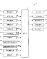
以下、図面を参照しながら、本発明の好ましい実施形態を詳細に説明する。図2に示すように、本実施形態による温度制御装置1は、後述する触媒10の温度制御を含む各種の制御を実行するためのECU2を備えており、図1に示す内燃機関(以下「エンジン」という)3に適用される。エンジン3は、車両(図示せず)に搭載されたディーゼルエンジンであり、例えば4つの気筒3a(1つのみ図示)を有している。
Hereinafter, preferred embodiments of the present invention will be described in detail with reference to the drawings. As shown in FIG. 2, the temperature control device 1 according to the present embodiment includes an ECU 2 for executing various controls including temperature control of the catalyst 10 described later, and an internal combustion engine shown in FIG. Apply to 3). The engine 3 is a diesel engine mounted on a vehicle (not shown), and has, for example, four cylinders 3a (only one is shown).
エンジン3のシリンダヘッド3bには、燃料噴射弁(以下「インジェクタ」という)4およびグロープラグ11が、燃焼室3cに臨むように取り付けられている。このインジェクタ4の開弁時間および開弁タイミングは、ECU2からの駆動信号によって制御され、それにより、燃料噴射量および燃料噴射時期が制御される。また、エンジン3では、エンジン3が冷間運転状態にないときには、吸気行程から圧縮行程までの間に燃料を1回のみ噴射するシングル噴射が実行される。また、エンジン3が冷間運転状態にあるときには、圧縮行程から膨張行程までの所定の期間に燃料を噴射するマルチ噴射が実行される。このマルチ噴射による燃料の噴射は、複数回(例えば5回)に分割して行われる。
A fuel injection valve (hereinafter referred to as "injector") 4 and a glow plug 11 are attached to the cylinder head 3b of the engine 3 so as to face the combustion chamber 3c. The valve opening time and the valve opening timing of the injector 4 are controlled by a drive signal from the ECU 2, whereby the fuel injection amount and the fuel injection timing are controlled. Further, in the engine 3, when the engine 3 is not in a cold operation state, single injection is performed in which fuel is injected only once from the intake stroke to the compression stroke. In addition, when the engine 3 is in a cold operation state, multi-injection in which fuel is injected in a predetermined period from the compression stroke to the expansion stroke is performed. The injection of fuel by this multi-injection is performed by dividing it into multiple times (for example, five times).
グロープラグ11は、気筒3a内の着火を補助するためのものである。このグロープラグ11は、電極を介してバッテリ(いずれも図示せず)に接続されており、バッテリから供給される電力によって発熱し、気筒3a内を加熱する。グロープラグ11の通電タイミングおよび通電時間は、ECU2からの制御信号によって制御される。
The glow plug 11 is for assisting ignition in the cylinder 3a. The glow plug 11 is connected to a battery (not shown) via an electrode, generates heat by the power supplied from the battery, and heats the inside of the cylinder 3a. The energization timing and the energization time of the glow plug 11 are controlled by a control signal from the ECU 2.
グロープラグ11には、筒内圧センサ21が取り付けられている(図2参照)。この筒内圧センサ21は、エンジン3の気筒3a内の圧力の変化量(以下「筒内圧変化量」という)DPを検出し、その検出信号をECU2に出力する。ECU2は、筒内圧変化量DPに基づいて、筒内圧PCYLを算出する。
An in-cylinder pressure sensor 21 is attached to the glow plug 11 (see FIG. 2). The in-cylinder pressure sensor 21 detects an amount of change in pressure (hereinafter referred to as “in-cylinder pressure change amount”) DP in the cylinder 3 a of the engine 3 and outputs a detection signal to the ECU 2. The ECU 2 calculates the in-cylinder pressure PCYL based on the in-cylinder pressure change amount DP.
エンジン3には、ターボチャージャ7が設けられている。このターボチャージャ7は、吸気通路5に設けられたコンプレッサブレード7aと、排気通路6に設けられ、コンプレッサブレード7aと一体に回転するタービンブレード7bと、複数の可変ベーン7c(2つのみ図示)と、可変ベーン7cを駆動するベーンアクチュエータ7dなどを備えている。
The engine 3 is provided with a turbocharger 7. The turbocharger 7 includes a compressor blade 7a provided in the intake passage 5, a turbine blade 7b provided in the exhaust passage 6 and integrally rotating with the compressor blade 7a, and a plurality of variable vanes 7c (only two are shown). , And a vane actuator 7d for driving the variable vane 7c.
このターボチャージャ7では、排気通路6を流れる排ガスによってタービンブレード7bが回転駆動されると、これと一体のコンプレッサブレード7aも同時に回転することによって、吸気を過給する過給動作が行われる。
In the turbocharger 7, when the turbine blade 7b is rotationally driven by the exhaust gas flowing through the exhaust passage 6, the compressor blade 7a integral therewith is also simultaneously rotated to perform a supercharging operation for supercharging the intake air.
可変ベーン7cは、タービンブレード7bを収容するハウジング(図示せず)の壁部に回動自在に取り付けられており、ベーンアクチュエータ7dに機械的に連結されている。可変ベーン7cの開度は、ECU2により、ベーンアクチュエータ7dを介して制御される。これにより、タービンブレード7bに吹き付けられる排ガスの量が変化するのに伴い、タービンブレード7bおよびコンプレッサブレード7aの回転速度が変化することによって、過給圧が制御される。
The variable vane 7c is rotatably attached to the wall of a housing (not shown) that accommodates the turbine blade 7b, and is mechanically coupled to the vane actuator 7d. The degree of opening of the variable vane 7c is controlled by the ECU 2 via the vane actuator 7d. As a result, as the amount of exhaust gas blown to the turbine blade 7 b changes, the rotational speed of the turbine blade 7 b and the compressor blade 7 a changes, whereby the supercharging pressure is controlled.
また、吸気通路5には、上流側から順に、エアフローセンサ22、吸気温センサ23、スロットル弁機構8および吸気圧センサ24が設けられている。エアフローセンサ22および吸気温センサ23は、コンプレッサブレード7aよりも上流側に設けられており、エンジン3に吸入される吸入空気量QAおよび吸気通路5内の温度(以下「吸気温」という)TAをそれぞれ検出し、それらを表す検出信号をECU2に出力する。吸気圧センサ24は、吸気通路5内の圧力(以下「吸気圧」という)PBを検出し、それを表す検出信号をECU2に出力する。
Further, an air flow sensor 22, an intake temperature sensor 23, a throttle valve mechanism 8 and an intake pressure sensor 24 are provided in the intake passage 5 sequentially from the upstream side. The air flow sensor 22 and the intake air temperature sensor 23 are provided on the upstream side of the compressor blade 7a, and the intake air amount QA drawn into the engine 3 and the temperature in the intake passage 5 (hereinafter referred to as "intake air temperature") TA It detects each and outputs the detection signal showing them to ECU2. The intake pressure sensor 24 detects a pressure in the intake passage 5 (hereinafter referred to as “intake pressure”) PB, and outputs a detection signal representing it to the ECU 2.
スロットル弁機構8は、スロットル弁8aおよびこれを駆動するTHアクチュエータ8bなどを備えている。スロットル弁8aは、吸気通路5内に回動自在に設けられている。THアクチュエータ8bは、モータと減速ギヤ機構(いずれも図示せず)を組み合わせたものである。スロットル弁8aの開度は、ECU2により、THアクチュエータ8bを介して制御され、それにより、スロットル弁8aを通過する吸入空気量が制御される。
The throttle valve mechanism 8 includes a throttle valve 8a and a TH actuator 8b for driving the same. The throttle valve 8 a is rotatably provided in the intake passage 5. The TH actuator 8 b is a combination of a motor and a reduction gear mechanism (neither is shown). The degree of opening of the throttle valve 8a is controlled by the ECU 2 via the TH actuator 8b, whereby the amount of intake air passing through the throttle valve 8a is controlled.
エンジン3には、EGR装置9が設けられている。このEGR装置9は、排気通路6に排出された排ガスの一部を吸気通路5に還流させるものであり、吸気通路5のコンプレッサブレード7aよりも下流側と排気通路6のタービンブレード7bよりも上流側に接続されたEGR通路9aと、このEGR通路9aを開閉するEGR制御弁9bなどで構成されている。
The engine 3 is provided with an EGR device 9. The EGR device 9 serves to recirculate a part of the exhaust gas discharged to the exhaust passage 6 to the intake passage 5, and is located downstream of the compressor blade 7 a of the intake passage 5 and upstream of the turbine blade 7 b of the exhaust passage 6. It comprises an EGR passage 9a connected to the side, an EGR control valve 9b for opening and closing the EGR passage 9a, and the like.
EGR制御弁9bは、そのリフトが最大値と最小値の間で連続的に変化する電磁弁で構成され、ECU2に電気的に接続されている。ECU2は、EGR制御弁9bを介して、EGR通路9aの開度を変化させることにより、EGR通路9aを介して還流する排ガスの還流量(以下「EGR量」という)を制御する。
The EGR control valve 9 b is constituted by a solenoid valve whose lift changes continuously between the maximum value and the minimum value, and is electrically connected to the ECU 2. The ECU 2 changes the opening degree of the EGR passage 9a through the EGR control valve 9b to control the amount of recirculation of the exhaust gas that is recirculated through the EGR passage 9a (hereinafter referred to as "EGR amount").
また、EGR通路9aには、EGR量センサ25が設けられている。このEGR量センサ25は、EGR通路9a内を通過するEGR量QEGRを検出し、それを表す検出信号をECU2に出力する。
Further, an EGR amount sensor 25 is provided in the EGR passage 9a. The EGR amount sensor 25 detects an EGR amount QEGR passing through the inside of the EGR passage 9a, and outputs a detection signal representing it to the ECU 2.
また、エンジン3には、クランク角センサ26が設けられている。このクランク角センサ26は、マグネットロータ26aおよびMREピックアップ26bで構成されており、クランクシャフト3dの回転に伴い、パルス信号であるCRK信号およびTDC信号をECU2に出力する。
Further, the engine 3 is provided with a crank angle sensor 26. The crank angle sensor 26 is composed of a magnet rotor 26a and an MRE pickup 26b, and outputs a CRK signal and a TDC signal as pulse signals to the ECU 2 as the crankshaft 3d rotates.
CRK信号は、所定クランク角(例えば1゜)ごとに出力される。ECU2は、このCRK信号に基づき、エンジン3の回転数(以下「エンジン回転数」という)NEを算出する。また、TDC信号は、各気筒3aのピストンが吸気行程の開始時の上死点よりも若干、手前の所定のクランク角位置にあることを表す信号であり、本実施形態のようにエンジン3が4気筒の場合には、クランク角180゜ごとに出力される。
The CRK signal is output every predetermined crank angle (for example, 1 °). The ECU 2 calculates the number of revolutions NE of the engine 3 (hereinafter referred to as "engine revolution number") based on the CRK signal. Further, the TDC signal is a signal indicating that the piston of each cylinder 3a is at a predetermined crank angle position slightly ahead of the top dead center at the start of the intake stroke, as in this embodiment, the engine 3 In the case of four cylinders, it is output at every crank angle of 180 °.
また、エンジン3には、気筒判別センサ(図示せず)が設けられている。この気筒判別センサは、気筒3aを判別するためのパルス信号である気筒判別信号を、ECU2に出力する。ECU2は、これらの気筒判別信号、CRK信号およびTDC信号に基づいて、クランク角CAを気筒3aごとに算出する。具体的には、このクランク角CAは、TDC信号の発生時に値0にリセットされ、1°ごとに出力されるCRK信号が発生するごとにインクリメントされる。
The engine 3 is also provided with a cylinder discrimination sensor (not shown). The cylinder discrimination sensor outputs a cylinder discrimination signal, which is a pulse signal for discriminating the cylinder 3a, to the ECU 2. The ECU 2 calculates the crank angle CA for each cylinder 3a based on the cylinder discrimination signal, the CRK signal and the TDC signal. Specifically, the crank angle CA is reset to a value of 0 when the TDC signal is generated, and is incremented each time the CRK signal output every 1 ° is generated.
エンジン3の本体には、水温センサ27が設けられている。この水温センサ27は、エンジン3のシリンダブロック(図示せず)内を循環する冷却水の温度(以下「エンジン水温」という)TWを検出し、それを表す検出信号をECU2に出力する。
A water temperature sensor 27 is provided on the main body of the engine 3. The water temperature sensor 27 detects a temperature (hereinafter referred to as “engine water temperature”) TW of cooling water circulating in a cylinder block (not shown) of the engine 3 and outputs a detection signal representing the temperature to the ECU 2.
前述した触媒10は、排気通路6のタービンブレード7bよりも下流側に設けられている。この触媒10は、例えば酸化触媒で構成されており、その温度が所定の活性温度TCATREFよりも高いときに、活性状態に保たれ、排気通路6を流れる排ガス中のHCやCOを酸化させることによって、排ガスを浄化する。
The catalyst 10 described above is provided downstream of the turbine blade 7 b of the exhaust passage 6. The catalyst 10 is made of, for example, an oxidation catalyst, and is maintained in an active state when its temperature is higher than a predetermined activation temperature TCATREF, thereby oxidizing HC and CO in the exhaust gas flowing through the exhaust passage 6. , To purify the exhaust gas.
また、排気通路6には、触媒前排ガス温度センサ28および触媒後排ガス温度センサ29が設けられている。触媒前排ガス温度センサ28は、触媒10のすぐ上流側の排ガスの温度(以下「触媒前排ガス温度」という)TCATBを検出し、それを表す検出信号をECU2に出力する。触媒後排ガス温度センサ29は、触媒10のすぐ下流側の排ガスの温度(以下「触媒後排ガス温度」という)TCATAを検出し、それを表す検出信号をECU2に出力する。
Further, the exhaust passage 6 is provided with a pre-catalyst exhaust gas temperature sensor 28 and a post-catalyst exhaust gas temperature sensor 29. The pre-catalyst exhaust gas temperature sensor 28 detects the temperature of the exhaust gas immediately upstream of the catalyst 10 (hereinafter referred to as “pre-catalyst exhaust gas temperature”) TCATB, and outputs a detection signal representing it to the ECU 2. The after-catalyst exhaust gas temperature sensor 29 detects the temperature of the exhaust gas immediately downstream of the catalyst 10 (hereinafter referred to as “after-catalyst exhaust gas temperature”) TCATA, and outputs a detection signal representing it to the ECU 2.
さらに、ECU2には、アクセル開度センサ30から、車両のアクセルペダル(図示せず)の踏み込み量(以下「アクセル開度」という)APを表す検出信号が、燃圧センサ31から、インジェクタ4から噴射される燃料の圧力(以下「燃圧」という)PFを表す検出信号が、それぞれ出力される。
Furthermore, a detection signal representing the depression amount (hereinafter referred to as “accelerator opening degree”) AP of the accelerator pedal (not shown) of the vehicle is injected from the accelerator pressure sensor 31 to the ECU 2 from the fuel pressure sensor 31. A detection signal representing a pressure of fuel (hereinafter referred to as “fuel pressure”) PF to be output is output.
ECU2は、CPU、RAM、ROMおよびI/Oインターフェース(いずれも図示せず)などから成るマイクロコンピュータで構成されている。ECU2は、前述した各種のセンサ21~31の検出信号などに応じて、エンジン3の運転状態を判別するとともに、判別した運転状態に応じて、前述したシングル噴射およびマルチ噴射を含む燃料噴射制御処理を実行する。この燃料噴射制御は、気筒判別信号に基づいて、気筒3aごとに行われるため、以下では、説明の便宜上、1つの気筒3aについて説明を行うものとする。
The ECU 2 is configured by a microcomputer including a CPU, a RAM, a ROM, an I / O interface (all not shown) and the like. The ECU 2 determines the operating state of the engine 3 according to the detection signals of the various sensors 21 to 31 described above, and the fuel injection control processing including the single injection and the multi injection described above according to the determined operating state. Run. Since this fuel injection control is performed for each cylinder 3a based on the cylinder discrimination signal, in the following, for convenience of explanation, the description will be made for one cylinder 3a.
シングル噴射による燃料噴射時期および燃料噴射量は、エンジン回転数NEおよび要求トルクPMCMDに応じ、それぞれの所定のマップ(いずれも図示せず)を検索することによって算出される。この要求トルクPMCMDは、エンジン回転数NEおよびアクセル開度APに応じ、所定のマップ(図示せず)を検索することによって算出される。
The fuel injection timing and the fuel injection amount by single injection are calculated by searching respective predetermined maps (neither of which are shown) according to the engine speed NE and the required torque PMCMD. The required torque PMCMD is calculated by searching a predetermined map (not shown) according to the engine speed NE and the accelerator opening AP.
なお、本実施形態では、ECU2が、燃料供給手段、運転状態検出手段、燃料供給タイミング設定手段、燃焼開始タイミング算出手段、目標燃焼開始タイミング設定手段、目標排ガス温度設定手段、熱発生率算出手段、制御手段および目標最大燃焼速度設定手段に相当する。
In the present embodiment, the ECU 2 includes a fuel supply unit, an operating condition detection unit, a fuel supply timing setting unit, a combustion start timing calculation unit, a target combustion start timing setting unit, a target exhaust gas temperature setting unit, a heat release rate calculation unit, It corresponds to the control means and the target maximum burning rate setting means.
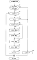
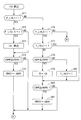
図3は、本発明の第1実施形態によるマルチ噴射を制御するマルチ噴射制御処理を示すフローチャートである。本処理は、TDC信号の発生間隔よりも短い所定の周期で実行される。なお、以下の説明では、マルチ噴射による1回目~5回目の燃料噴射の時期をそれぞれ第1~第5燃料噴射時期TINJ1~TINJ5とし、1回目~5回目の燃料噴射によって噴射される燃料噴射量をそれぞれ第1~第5燃料噴射量QINJ1~QINJ5とし、これらの第1~第5燃料噴射時期TINJ1~TINJ5および第1~第5燃料噴射量QINJ1~QINJ5を適宜、燃料噴射時期TINJnおよび燃料噴射量QINJnという。両者の添え字nは、マルチ噴射による燃料の噴射次数(何回目の噴射であるか(n=1~5))を表す。
FIG. 3 is a flowchart showing multi-injection control processing for controlling multi-injection according to the first embodiment of the present invention. The present process is executed at a predetermined cycle shorter than the generation interval of the TDC signal. In the following description, the fuel injection amounts to be injected by the first to fifth fuel injections are defined as the first to fifth fuel injection timings TINJ1 to TINJ5, respectively, for the first to fifth fuel injections by multi injection. The first to fifth fuel injection amounts QINJ1 to QINJ5, respectively, and the first to fifth fuel injection timings TINJ1 to TINJ5 and the first to fifth fuel injection amounts QINJ1 to QINJ5 are appropriately set to the fuel injection timing TINJn and the fuel injection It is called the quantity QINJn. Both subscripts n indicate the order of injection of fuel by multi-injection (how many injections have been made (n = 1 to 5)).
本処理では、まずステップ1(「S1」と図示。以下同じ)において、エンジン水温TWが所定温度TWREF以下で、かつ吸気温TAが所定温度TAREF以下であるか否かを判別する。この判別結果がYESのときには、エンジン3が冷間運転状態にあると判定し、マルチ噴射による燃料噴射時期TINJnおよび燃料噴射量QINJnの算出中であることを表す算出中フラグF_CALが「1」であるか否かを判別する(ステップ2)。この算出中フラグF_CALは、TDC信号の発生に同期して「1」にセットされるものである。また、このTDC信号の発生に同期して、前記噴射次数nが値1に初期化される。
In this process, first, at step 1 (shown as “S1”, the same applies to the following), it is determined whether the engine coolant temperature TW is less than a predetermined temperature TWREF and the intake air temperature TA is less than a predetermined temperature TAREF. When the result of this determination is YES, it is determined that the engine 3 is in a cold operation state, and the in-calculation flag F_CAL indicating that the fuel injection timing TINJn and fuel injection amount QINJn are being calculated by multi injection is "1". It is determined whether there is any (step 2). The in-calculation flag F_CAL is set to "1" in synchronization with the generation of the TDC signal. Also, the injection order n is initialized to the value 1 in synchronization with the generation of this TDC signal.
このステップ2の判別結果がYESのときには、噴射次数nが値5よりも大きいか否かを判別する(ステップ3)。この判別結果がNOのときには、算出中フラグF_CALが前回と今回の間で「0」から「1」に変化したか否かを判別する(ステップ4)。
If the result of the determination in step 2 is YES, it is determined whether the injection order n is larger than the value 5 (step 3). When the result of this determination is NO, it is determined whether or not the under-calculation flag F_CAL has changed from "0" to "1" between the previous time and this time (step 4).
この判別結果がYESのとき、すなわち算出中フラグF_CALが「1」にセットされた最初のループのときには、目標排ガス温度TEMCMDを算出する(ステップ5)。
When the result of this determination is YES, that is, in the first loop in which the in-calculation flag F_CAL is set to "1", the target exhaust gas temperature TEMCMD is calculated (step 5).
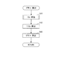
図4は、この目標排ガス温度TEMCMDの算出処理を示すサブルーチンである。本処理では、まずステップ21において、触媒前排ガス温度センサ28および触媒後排ガス温度センサ29でそれぞれ検出された触媒前排ガス温度TCATBおよび触媒後排ガス温度TCATAに基づいて、触媒10の温度(以下「触媒温度」という)TCATを推定する。具体的には、触媒温度TCATは、触媒前排ガス温度TCATBと触媒後排ガス温度TCATAとの加重平均によって算出される。
FIG. 4 is a subroutine showing the process of calculating the target exhaust gas temperature TEMCMD. In the present process, first, in step 21, the temperature of the catalyst 10 (hereinafter referred to as “the catalyst based on the pre-catalyst exhaust gas temperature TCATB and the post-catalyst exhaust gas temperature TCATA detected by the pre-catalyst exhaust gas temperature sensor 28 and the post-catalyst exhaust gas temperature sensor 29, respectively. Estimate temperature)). Specifically, the catalyst temperature TCAT is calculated by a weighted average of the pre-catalyst exhaust gas temperature TCATB and the post-catalyst exhaust gas temperature TCATA.
次に、算出された触媒温度TCATが前記活性温度TCATREF以下であるか否かを判別する(ステップ22)。この判別結果がYESで、触媒温度TCATが活性温度TCATREF以下のときには、触媒10が活性状態にないと判定して、触媒温度TCATに第1所定温度TREF1(例えば20度)を加算した値を目標排ガス温度TEMCMDとして設定し(ステップ23)、本処理を終了する。
Next, it is determined whether the calculated catalyst temperature TCAT is less than or equal to the activation temperature TCATREF (step 22). When the determination result is YES and the catalyst temperature TCAT is lower than the activation temperature TCATREF, it is determined that the catalyst 10 is not in the activated state, and a value obtained by adding a first predetermined temperature TREF1 (for example, 20 degrees) to the catalyst temperature TCAT is a target The exhaust gas temperature TEMCMD is set (step 23), and the process ends.
一方、ステップ22の判別結果がNOで、触媒温度TCATが活性温度TCATREFよりも高いときには、触媒10が活性状態にあると判定して、活性温度TCATREFから第2所定温度TREF2(例えば10度)を減算した値を目標排ガス温度TEMCMDとして設定し(ステップ24)、本処理を終了する。
On the other hand, when the determination result in step 22 is NO and the catalyst temperature TCAT is higher than the activation temperature TCATREF, it is determined that the catalyst 10 is in the activated state, and the second predetermined temperature TREF2 (for example, 10 degrees) is determined from the activation temperature TCATREF. The value thus subtracted is set as the target exhaust gas temperature TEMCMD (step 24), and the present process is ended.
図3に戻り、前記ステップ5に続くステップ6では、算出した目標排ガス温度TEMCMDに応じ、所定のマップ(図示せず)を検索することによって、目標吸入空気量QACMDを算出する。検出された吸入空気量QAがこの目標吸入空気量QACMDになるように、THアクチュエータ8bが制御されることで、吸入空気量QAが目標吸入空気量QACMDに収束するようにフィードバック制御される。
Returning to FIG. 3, in step 6 following step 5, the target intake air amount QACMD is calculated by searching a predetermined map (not shown) according to the calculated target exhaust gas temperature TEMCMD. By controlling the TH actuator 8b so that the detected intake air amount QA becomes the target intake air amount QACMD, feedback control is performed such that the intake air amount QA converges to the target intake air amount QACMD.
次いで、噴射次数nに対する燃料噴射時期TINJnを算出する(ステップ7)とともに、燃料噴射量QINJnを算出する(ステップ8)。これらの算出処理については後述する。なお、燃料噴射時期TINJnは、燃料が噴射されるときのクランク角CAで表される。前述したように、噴射次数nは、算出中フラグF_CALと同様、TDC信号の発生に同期して値1にリセットされるため、前記ステップ4の判別結果がYESのときには、噴射次数n=1になり、それに応じて、ステップ7および8では、燃料噴射時期TINJnおよび燃料噴射量QINJnとして、第1燃料噴射時期TINJ1および第1燃料噴射量QINJ1がそれぞれ算出される。
Next, the fuel injection timing TINJn for the injection order n is calculated (step 7), and the fuel injection amount QINJn is calculated (step 8). These calculation processes will be described later. The fuel injection timing TINJn is represented by a crank angle CA when fuel is injected. As described above, since the injection order n is reset to the value 1 in synchronization with the generation of the TDC signal as in the case of the calculation under calculation flag F_CAL, the injection order n is set to 1 when the determination result in step 4 is YES. Accordingly, in steps 7 and 8, the first fuel injection timing TINJ1 and the first fuel injection amount QINJ1 are respectively calculated as the fuel injection timing TINJn and the fuel injection amount QINJn.
そして、噴射次数nをインクリメントし(ステップ9)、本処理を終了する。このステップ9の実行により、次回のループでは、噴射次数n=2になるとともに、前記ステップ4の判別結果がNOになり、その場合には、前記ステップ5および6をスキップし、前記ステップ7に進み、燃料噴射時期TINJnおよび燃料噴射量QINJnとして、第2燃料噴射時期TINJ2および第2燃料噴射量QINJ2をそれぞれ算出する。その後、前記ステップ9を実行し、本処理を終了する。
Then, the injection order n is incremented (step 9), and the present process is ended. By the execution of this step 9, in the next loop, the injection order n becomes 2 and the determination result of the above step 4 becomes NO. In this case, the above steps 5 and 6 are skipped. Next, the second fuel injection timing TINJ2 and the second fuel injection amount QINJ2 are calculated as the fuel injection timing TINJn and the fuel injection amount QINJn, respectively. Thereafter, step 9 is executed to end the present process.
その後、前記ステップ7および8が繰り返し実行されることによって、第3~第5燃料噴射時期TINJ3~TINJ5および第3~第5燃料噴射量QINJ3~QINJ5が順次、算出される。また、第5燃料噴射時期TINJ5および第5燃料噴射量QINJ5の算出の終了直後には、前記ステップ9の実行により、噴射次数nが値5を上回ることで、前記ステップ3の判別結果がYESになる。その場合には、第1~第5燃料噴射時期TINJ1~TINJ5および第1~第5燃料噴射量QINJ1~QINJ5のすべての算出が終了したとして、算出中フラグF_CALを「0」にリセットし(ステップ10)、本処理を終了する。このステップ10の実行により、前記ステップ2の判別結果がNOになり、その場合には、本処理をそのまま終了する。
After that, the third to fifth fuel injection timings TINJ3 to TINJ5 and the third to fifth fuel injection amounts QINJ3 to QINJ5 are sequentially calculated by repeatedly executing the steps 7 and 8. In addition, immediately after the end of the calculation of the fifth fuel injection timing TINJ5 and the fifth fuel injection amount QINJ5, the injection order n exceeds the value 5 by the execution of the step 9, so that the result of the determination of the step 3 becomes YES. Become. In that case, the calculation in progress flag F_CAL is reset to "0" assuming that all calculations of the first to fifth fuel injection timings TINJ1 to TINJ5 and the first to fifth fuel injection amounts QINJ1 to QINJ5 are completed (step 10) End this process. By the execution of this step 10, the judgment result of the above-mentioned step 2 becomes NO, and in this case, the present processing ends.
一方、前記ステップ1の判別結果がNOのとき、すなわちエンジン水温TWが所定温度TWREFよりも高いとき、または吸気温TAが所定温度TAREFよりも高いときには、エンジン水温TWや吸気温TAが比較的高く、エンジン3が冷間運転状態にないと判定し、前記ステップ10を実行し、本処理を終了する。
On the other hand, when the determination result in step 1 is NO, that is, when the engine coolant temperature TW is higher than the predetermined temperature TWREF, or when the intake air temperature TA is higher than the predetermined temperature TAREF, the engine water temperature TW and the intake air temperature TA are relatively high. Then, it is determined that the engine 3 is not in the cold operation state, the above-mentioned step 10 is executed, and the present process is ended.
以上のようにして算出された第1~第5燃料噴射時期TINJ1~TINJ5および第1~第5燃料噴射量QINJ1~QINJ5に基づいて、インジェクタ4の開弁タイミングおよび開弁時間を制御することによって、マルチ噴射による5回の分割噴射が実行される。
By controlling the valve opening timing and the valve opening time of the injector 4 based on the first to fifth fuel injection timings TINJ1 to TINJ5 and the first to fifth fuel injection amounts QINJ1 to QINJ5 calculated as described above , Five split injections by multi-injection are performed.
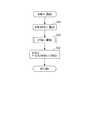
図5は、前記ステップ7で実行される燃料噴射時期TINJnの算出処理を示すサブルーチンである。なお、第1~第5燃料噴射時期TINJ1~TINJ5の算出方法は、基本的には互いに同じであるため、以下では、噴射次数n=1、すなわち第1燃料噴射時期TINJ1の場合を中心として説明を行うものとする。
FIG. 5 is a subroutine showing the process of calculating the fuel injection timing TINJn executed in step 7 described above. The calculation methods of the first to fifth fuel injection timings TINJ1 to TINJ5 are basically the same as each other, so in the following, the explanation will be made focusing on the injection order n = 1, that is, the first fuel injection timing TINJ1. Shall be
本処理では、まずステップ31において、燃料噴射時期の基本値TINJBASEnを算出する。具体的には、エンジン回転数NE、要求トルクPMCMD、目標吸入空気量QACMD、および前記ステップ23または24で算出された目標排ガス温度TEMCMDに応じ、所定の第1燃料噴射時期マップ(図示せず)を検索することによって、燃料噴射時期の第1基本値TINJBASE1を算出する。この第1燃料噴射時期マップでは、第1基本値TINJBASE1は、燃料の良好な着火性を確保するために、膨張行程の開始時付近に設定されており、より詳しくは、目標吸入空気量QACMDが少ないほど、より進角側に設定されている。また、第1基本値TINJBASE1は、エンジン回転数NEが低いほど、また要求トルクPMCMDが低いほど、より低い温度状態にある排ガスの温度を上昇させるために、より遅角側に設定されている。
In the present process, first, at step 31, a basic value TINJBASEn of the fuel injection timing is calculated. Specifically, according to the engine rotational speed NE, the required torque PMCMD, the target intake air amount QACMD, and the target exhaust gas temperature TEMCMD calculated in the step 23 or 24, a predetermined first fuel injection timing map (not shown) Is calculated to calculate the first basic value TINJBASE1 of the fuel injection timing. In this first fuel injection timing map, the first basic value TINJBASE1 is set near the start of the expansion stroke in order to secure good ignition performance of the fuel, and more specifically, the target intake air amount QACMD is The smaller the number, the more advanced the angle is. Further, the first basic value TINJBASE1 is set more retarded in order to raise the temperature of the exhaust gas in a lower temperature state as the engine rotational speed NE is lower and the required torque PMCMD is lower.
次に、第1環境補正値CENV1を算出する(ステップ32)。この第1環境補正値CENVnの算出は、吸気温TA、吸気圧PB、EGR量QEGR、燃圧PF、燃料の性状、エンジン3の暖機状態やグロープラグ11の通電状態などに応じ、それぞれの所定のマップ(図示せず)を検索することによって、補正値をそれぞれ算出するとともに、これらの補正値を互いに加算することによって行われる。なお、上記の燃料の性状は、例えばシングル噴射による燃料の実際の燃焼開始タイミングと目標燃焼開始タイミングに応じて算出され、エンジン3の暖機状態は、始動時からの燃料噴射量の積算値などにより推定された気筒3aの壁面温度などに応じて判定される。
Next, a first environmental correction value CENV1 is calculated (step 32). The first environmental correction value CENVn is calculated in accordance with the intake temperature TA, the intake pressure PB, the EGR amount QEGR, the fuel pressure PF, the properties of the fuel, the warm-up state of the engine 3, the energized state of the glow plug 11, etc. The correction values are calculated respectively by searching the maps (not shown) of and the correction values are added to each other. The property of the above fuel is calculated according to, for example, the actual combustion start timing of the fuel by single injection and the target combustion start timing, and the warm-up state of the engine 3 is the integrated value of the fuel injection amount from the start time It is determined in accordance with the wall surface temperature of the cylinder 3a estimated by the above equation.
次いで、第1フィードバック補正値CFBI1を後述するようにして算出する(ステップ33)。そして、算出した第1基本値TINJBASE1に、第1環境補正値CENV1および第1フィードバック補正値CFBI1を加算することによって、第1燃料噴射時期TINJ1を算出し(ステップ34)、本処理を終了する。
Next, the first feedback correction value CFBI1 is calculated as described later (step 33). Then, the first fuel injection timing TINJ1 is calculated by adding the first environment correction value CENV1 and the first feedback correction value CFBI1 to the calculated first basic value TINJBASE1 (step 34), and the present process is ended.
また、噴射次数n=2の場合には、第1燃料噴射時期TINJ1の場合と同様にして、前記ステップ31~34において、第2燃料噴射時期TINJ2を算出する。具体的には、ステップ31において、エンジン回転数NE、要求トルクPMCMD、目標吸入空気量QACMDおよび目標排ガス温度TEMCMDに応じ、所定の第2燃料噴射時期マップ(図示せず)を検索することによって、燃料噴射時期の第2基本値TINJBASE2を算出する。次に、吸気温TA、吸気圧PB、EGR量QEGR、燃圧PFや燃料の性状などに応じて、第2環境補正値CENV2を算出するとともに、第2フィードバック補正値CFBI2を算出する(ステップ32および33)。そして、第2基本値TINJBASE2に、第2環境補正値CENV2および第2フィードバック補正値CENV2を加算することによって、第2燃料噴射時期TINJ2を算出する(ステップ34)。
Further, in the case of the injection order n = 2, in the same manner as in the case of the first fuel injection timing TINJ1, the second fuel injection timing TINJ2 is calculated in the steps 31 to 34. Specifically, in step 31, a predetermined second fuel injection timing map (not shown) is searched according to the engine rotational speed NE, the required torque PMCMD, the target intake air amount QACMD and the target exhaust gas temperature TEMCMD. A second basic value TINJBASE2 of the fuel injection timing is calculated. Next, a second environmental correction value CENV2 is calculated and a second feedback correction value CFBI2 is calculated according to the intake air temperature TA, the intake pressure PB, the EGR amount QEGR, the fuel pressure PF, and the properties of the fuel (step 32 and 33). Then, the second fuel injection timing TINJ2 is calculated by adding the second environment correction value CENV2 and the second feedback correction value CENV2 to the second basic value TINJBASE2 (step 34).
同様に、噴射次数n=3~5の場合には、エンジン回転数NEなどに応じて、所定の第3~第5燃料噴射時期マップ(いずれも図示せず)を検索することによって、燃料噴射時期の第3~第5基本値TINJBASE3~TINJBASE5をそれぞれ算出する(ステップ31)。
Similarly, in the case of the injection order n = 3 to 5, according to the engine speed NE etc., the fuel injection is performed by searching predetermined third to fifth fuel injection timing maps (all not shown). Third to fifth basic values TINJBASE3 to TINJBASE5 of the period are respectively calculated (step 31).
次に、算出した第3~第5基本値TINJBASE3~TINJBASE5に、ステップ32で算出した第3~第5環境補正値CENV3~CENV5、およびステップ33で算出した第3~第5フィードバック補正値CENV3~CENV5をそれぞれ加算することによって、第3~第5燃料噴射時期TINJ3~TINJ5を算出する(ステップ34)。
Next, the third to fifth environment correction values CENV3 to CENV calculated in step 32 and the third to fifth feedback correction values CENV3 calculated in step 33 are added to the calculated third to fifth basic values TINJBASE3 to TINJBASE5. Third to fifth fuel injection timings TINJ3 to TINJ5 are calculated by adding CENV5 (step 34).
図6は、前記ステップ33で実行されるフィードバック補正値CFBInの算出処理を示すサブルーチンである。なお、第1~第5フィードバック補正値CFBI1~CFBI5の算出方法は、基本的には互いに同じであるため、以下では、噴射次数n=1、すなわち第1フィードバック補正値CFBI1の場合を中心として説明を行うものとする。
FIG. 6 is a subroutine showing the process of calculating the feedback correction value CFBIn executed in step 33. The calculation methods of the first to fifth feedback correction values CFBI1 to CFBI5 are basically the same as each other, and therefore, in the following, the explanation will be made focusing on the case of the injection order n = 1, that is, the first feedback correction value CFBI1. Shall be
本処理では、まずステップ41において、1回目の燃料噴射による燃料が実際に燃焼を開始した時期を第1実燃焼時期IG1として算出する。この算出処理については後述する。
In the present process, first, at step 41, the time when the fuel by the first fuel injection has actually started combustion is calculated as a first actual combustion time IG1. The calculation process will be described later.
次に、目標排ガス温度TEMCMDおよび要求トルクPMCMDに応じ、所定のマップ(図示せず)を検索することによって、第1実燃焼時期IG1の目標となる第1目標燃焼時期TIG1を算出する(ステップ42)。
Next, a first target combustion timing TIG1 to be a target of the first actual combustion timing IG1 is calculated by searching a predetermined map (not shown) according to the target exhaust gas temperature TEMCMD and the required torque PMCMD (step 42) ).
次いで、算出した第1実燃焼時期IG1および第1目標燃焼時期TIG1に応じて、燃料噴射時期の第1フィードバック補正値CFBI1を算出し(ステップ43)、本処理を終了する。この第1フィードバック補正値CFBI1の算出は、第1実燃焼時期IG1が第1目標燃焼時期TIG1に収束するよう、例えばPIDフィードバック制御によって行われる。
Next, a first feedback correction value CFBI1 for the fuel injection timing is calculated according to the calculated first actual combustion timing IG1 and the first target combustion timing TIG1 (step 43), and the present process is terminated. The calculation of the first feedback correction value CFBI1 is performed by, for example, PID feedback control so that the first actual combustion timing IG1 converges to the first target combustion timing TIG1.
以下、噴射次数n=2~5の場合にも、第1フィードバック補正値CFBI1の場合と同様、第2~第5実燃焼時期IG2~IG5を算出する(ステップ41)とともに、目標排ガス温度TEMCMDなどに応じ、それぞれの所定のマップを検索することによって、第2~第5目標燃焼時期TIG2~TIG5を算出する(ステップ42)。そして、これらの第2~第5実燃焼時期IG2~IG5および第2~第5目標燃焼時期TIG2~TIG5に応じて、第2~第5フィードバック補正値CFBI2~CFBI5をそれぞれ算出する(ステップ43)。
Hereinafter, in the case of the injection order n = 2 to 5, similarly to the case of the first feedback correction value CFBI1, the second to fifth actual combustion timings IG2 to IG5 are calculated (step 41), the target exhaust gas temperature TEMCMD, etc. Accordingly, the second to fifth target combustion timings TIG2 to TIG5 are calculated by searching the respective predetermined maps (step 42). Then, second to fifth feedback correction values CFBI2 to CFBI5 are respectively calculated according to the second to fifth actual combustion timings IG2 to IG5 and the second to fifth target combustion timings TIG2 to TIG5 (step 43). .
なお、これらのマップでは、第1~第5目標燃焼時期TIG1~TIG5は、後述する第1燃焼期間の開始時から第5燃焼期間の終了時までの間で(図12参照)、燃焼が継続して行われるように設定されている。また、第1~第5目標燃焼時期TIG1~TIG5は、目標排ガス温度TEMCMDが高いほど、第1~第5燃焼期間のそれぞれの長さが長くなるように設定されている。これは、第1~第5燃焼期間が長いほど、1燃焼サイクルにおける全体の燃焼期間が長くなることで、排ガスの温度をより上昇させることができるからである。
In these maps, the first to fifth target combustion timings TIG1 to TIG5 continue combustion between the start of the first combustion period to be described later and the end of the fifth combustion period (see FIG. 12). Is set to be done. Further, the first to fifth target combustion timings TIG1 to TIG5 are set such that the lengths of the first to fifth combustion periods become longer as the target exhaust gas temperature TEMCMD becomes higher. This is because the temperature of the exhaust gas can be further raised by prolonging the entire combustion period in one combustion cycle as the first to fifth combustion periods are longer.
図7は、前記ステップ8で実行される燃料噴射量QINJnの算出処理のサブルーチンを示している。なお、第1~第5燃料噴射量QINJ1~QINJ5の算出方法は、基本的に互いに同じであるため、以下では、噴射次数n=1、すなわち第1燃料噴射量QINJ1の場合を中心として説明を行うものとする。
FIG. 7 shows a subroutine of the process of calculating the fuel injection amount QINJn executed in step 8 described above. The calculation methods of the first to fifth fuel injection amounts QINJ1 to QINJ5 are basically the same as each other, and therefore, in the following, the description will be mainly made on the case of the injection order n = 1, ie, the first fuel injection amount QINJ1. Assumed to be performed.
本処理では、まずステップ51において、エンジン回転数NE、要求トルクPMCMD、目標排ガス温度TEMCMDおよび第1燃料噴射時期TINJ1に応じ、所定の第1燃料噴射量マップ(図示せず)を検索することによって、燃料噴射量の第1基本値QINJBASE1を算出する。
In this process, first, at step 51, a predetermined first fuel injection amount map (not shown) is searched according to the engine rotational speed NE, the required torque PMCMD, the target exhaust gas temperature TEMCMD and the first fuel injection timing TINJ1. The first basic value QINJBASE1 of the fuel injection amount is calculated.
次に、第1フィードバック補正値CFBQ1を後述するようにして算出する(ステップ52)。そして、算出した第1基本値QINJBASE1に第1フィードバック補正値CFBQ1を加算することによって、第1燃料噴射量QINJ1を算出し(ステップ53)、本処理を終了する。
Next, the first feedback correction value CFBQ1 is calculated as described later (step 52). Then, the first fuel injection amount QINJ1 is calculated by adding the first feedback correction value CFBQ1 to the calculated first basic value QINJBASE1 (step 53), and the present process is ended.
以下、噴射次数n=2~5の場合にも、第1燃料噴射量QINJ1の場合と同様、第2~第5燃料噴射時期TINJ2~TINJ5などに応じ、所定の第2~第5燃料噴射量マップ(いずれも図示せず)を検索することによって、燃料噴射量の第2~第5基本値QINJBASE2~QINJBASE5をそれぞれ算出し(ステップ51)、これらの第2~第5基本値QINJBASE2~QINJBASE5に、ステップ52で算出した第2~第5フィードバック補正値CFBQ2~CFBQ5を加算することによって、第2~第5燃料噴射量QINJ2~QINJ5を算出する(ステップ53)。なお、上記の第1~第5燃料噴射量マップでは、第1~第5基本値QINJBASE1~QINJBASE5はそれぞれ、目標排ガス温度TEMCMDが高いほど、より大きな値に設定されている。
Hereinafter, also in the case of the injection order n = 2 to 5, similarly to the case of the first fuel injection amount QINJ1, according to the second to fifth fuel injection timings TINJ2 to TINJ5, etc., predetermined second to fifth fuel injection amounts The second to fifth basic values QINJBASE2 to QINJBASE5 of the fuel injection amount are calculated respectively by searching the map (all not shown) (step 51), and these second to fifth basic values QINJBASE2 to QINJBASE5 are calculated. The second to fifth fuel injection amounts QINJ2 to QINJ5 are calculated by adding the second to fifth feedback correction values CFBQ2 to CFBQ5 calculated at step 52 (step 53). In the above first to fifth fuel injection amount maps, the first to fifth basic values QINJBASE1 to QINJBASE5 are set to larger values as the target exhaust gas temperature TEMCMD is higher.
図8は、前記ステップ52で実行されるフィードバック補正値CFBQnの算出処理を示すサブルーチンである。本処理では、まずステップ61において、噴射次数nが値1であるか否かを判別する。この判別結果がYESのときには、目標排ガス温度TEMCMDおよび要求トルクPMCMDに応じ、所定のマップ(図示せず)を検索することによって、目標最大燃焼速度TVMAXを算出する(ステップ62)。
FIG. 8 is a subroutine showing the process of calculating the feedback correction value CFBQn executed in step 52. In the present process, first, at step 61, it is determined whether or not the injection order n has a value of one. If the answer to this question is affirmative (YES), a target maximum combustion rate TVMAX is calculated by searching a predetermined map (not shown) according to the target exhaust gas temperature TEMCMD and the required torque PMCMD (step 62).
次に、第1燃焼期間における第1最大燃焼速度VMAX1を読み込む(ステップ63)。この第1最大燃焼速度VMAX1は、後述する実燃焼時期IGnの算出サブルーチンにおいて、実燃焼時期IGnと併せて算出される。そして、算出した目標最大燃焼速度TVMAXおよび第1最大燃焼速度VMAX1に応じて、燃料噴射量の第1フィードバック補正値CFBQ1を算出し(ステップ64)、本処理を終了する。このフィードバック補正値CFBQnの算出は、第1最大燃焼速度VMAX1が目標最大燃焼速度TVMAXに収束するよう、例えばPIDフィードバック制御によって行われる。
Next, the first maximum combustion rate VMAX1 in the first combustion period is read (step 63). The first maximum combustion velocity VMAX1 is calculated together with the actual combustion timing IGn in a calculation subroutine of the actual combustion timing IGN to be described later. Then, the first feedback correction value CFBQ1 of the fuel injection amount is calculated according to the calculated target maximum combustion speed TVMAX and the first maximum combustion speed VMAX1 (step 64), and the present process is terminated. The calculation of the feedback correction value CFBQn is performed by, for example, PID feedback control so that the first maximum combustion speed VMAX1 converges to the target maximum combustion speed TVMAX.
一方、前記ステップ61の判別結果がNOのとき、すなわち噴射次数n=2~5のときには、前記ステップ62をスキップし、前記ステップ63以降を実行することによって、第2~第5フィードバック補正値CFBQ2~CFBQ5をそれぞれ算出する。
On the other hand, when the result of the determination in the step 61 is NO, that is, when the injection order n is 2 to 5, the step 62 is skipped and the steps 63 and subsequent steps are executed to obtain the second to fifth feedback correction values CFBQ2. Calculate CFBQ5 respectively.
具体的には、第1フィードバック補正値CFBQ1の場合と同様、第2~第5燃焼期間における第2~第5最大燃焼速度VMAX2~VMAX5を読み込み(ステップ63)、これらの第2~第5最大燃焼速度VMAX2~VMAX5、および前記ステップ62で算出した目標最大燃焼速度TVMAXに応じて、第2~第5フィードバック補正値CFBQ2~CFBQ5を算出する(ステップ64)。
Specifically, as in the case of the first feedback correction value CFBQ1, the second to fifth maximum combustion speeds VMAX2 to VMAX5 in the second to fifth combustion periods are read (step 63), and these second to fifth maximum values are read. Second to fifth feedback correction values CFBQ2 to CFBQ5 are calculated according to the combustion speeds VMAX2 to VMAX5 and the target maximum combustion speed TVMAX calculated at step 62 (step 64).
図9~図11は、前記ステップ41で実行される実燃焼時期IGnの算出処理を示すサブルーチンである。本処理は、第1~第5燃焼期間において実燃焼時期IGnを、最大燃焼速度VMAXnと併せて算出するものである。また、これらの第1~第5燃焼期間はそれぞれ、図12に示すように、第1および第2燃料噴射時期TINJ1,TINJ2の間の期間、第2および第3燃料噴射時期TINJ2,TINJ3の間の期間、第3および第4燃料噴射時期TINJ3,TINJ4の間の期間、第4および第5燃料噴射時期TINJ4,TINJ5の間の期間、ならびに第5燃料噴射時期TINJ5と所定クランク角CAREFとの間の期間として定義される。
FIGS. 9 to 11 are subroutines showing the process of calculating the actual combustion time IGn executed in the step 41. The present process is to calculate the actual combustion timing IGn in the first to fifth combustion periods together with the maximum combustion velocity VMAXn. Also, as shown in FIG. 12, these first to fifth combustion periods are the periods between the first and second fuel injection timings TINJ1 and TINJ2, and between the second and third fuel injection timings TINJ2 and TINJ3, respectively. Period, the period between the third and fourth fuel injection timings TINJ3, TINJ4, the period between the fourth and fifth fuel injection timings TINJ4, TINJ5, and the fifth fuel injection timing TINJ5 and the predetermined crank angle CAREF Defined as a period of
本処理では、まずステップ71において、第1燃焼期間フラグF_LINJ1が「1」であるか否かを判別する。この第1燃焼期間フラグF_LINJ1は、第1燃焼期間内にあるときに「1」にセットされるものである。このステップ71の判別結果がYESで、第1燃焼期間内のときには、第1燃焼期間フラグF_LINJ1が前回と今回の間で「0」から「1」に変化したか否かを判別する(ステップ72)。この判別結果がYESで、1回目の燃料噴射の開始直後には、後述する熱発生率dQHRが上昇し始めたタイミングを検出し、このタイミングを第1実燃焼時期IG1として算出した(ステップ73)後、ステップ74に進む。
In this process, first, at step 71, it is judged if the first combustion period flag F_LINJ1 is "1". The first combustion period flag F_LINJ1 is set to "1" when within the first combustion period. If the determination result in this step 71 is YES, that is, within the first combustion period, it is determined whether or not the first combustion period flag F_LINJ1 has changed from “0” to “1” between the previous time and this time (step 72) ). The determination result is YES, and immediately after the start of the first fuel injection, the timing at which the heat release rate dQHR described later starts to increase is detected, and this timing is calculated as the first actual combustion timing IG1 (step 73) Thereafter, the process proceeds to step 74.
一方、ステップ72の判別結果がNOのときには、前記ステップ73をスキップし、ステップ74に進む。
On the other hand, when the result of the determination in step 72 is NO, the step 73 is skipped, and the process proceeds to step 74.
このステップ74では、熱発生率dQHRがその前回値dQHRZ以上であるか否かを判別する。この熱発生率dQHRは、単位クランク角当たりの熱発生量であり、筒内圧センサ21で検出された筒内圧PCYLを用い、次式(1)に従って算出される。
dQHR=(κ×PCYL×1000×dVθ+dPCYL×1000×Vθ)/(κ-1) ・・・(1)
dQHR:熱発生率
κ:混合気の比熱比
PCYL:筒内圧
dVθ:筒内容積変化率
dPCYL:筒内圧変化率
Vθ:筒内容積
ここで、比熱比κは所定値(例えば1.34)に設定されている。また、筒内容積変化率dVθおよび筒内容積Vθは、いずれもクランク角CAに基づいて算出される。 In step 74, it is determined whether the heat release rate dQHR is equal to or higher than the previous value dQHRZ. The heat release rate dQHR is a heat release amount per unit crank angle, and is calculated according to the following equation (1) using the in-cylinder pressure PCYL detected by the in-cylinder pressure sensor 21.
dQHR = (κ × PCYL × 1000 × dVθ + dPCYL × 1000 × Vθ) / (κ−1) (1)
dQHR: heat release rate κ: specific heat ratio of air-fuel mixture PCYL: in-cylinder pressure dVθ: in-cylinder volume change rate dPCYL: in-cylinder pressure change rate Vθ: in-cylinder volume Here, the specific heat ratio κ is a predetermined value (eg, 1.34) It is set. The in-cylinder volume change rate dVθ and the in-cylinder volume Vθ are both calculated based on the crank angle CA.
dQHR=(κ×PCYL×1000×dVθ+dPCYL×1000×Vθ)/(κ-1) ・・・(1)
dQHR:熱発生率
κ:混合気の比熱比
PCYL:筒内圧
dVθ:筒内容積変化率
dPCYL:筒内圧変化率
Vθ:筒内容積
ここで、比熱比κは所定値(例えば1.34)に設定されている。また、筒内容積変化率dVθおよび筒内容積Vθは、いずれもクランク角CAに基づいて算出される。 In step 74, it is determined whether the heat release rate dQHR is equal to or higher than the previous value dQHRZ. The heat release rate dQHR is a heat release amount per unit crank angle, and is calculated according to the following equation (1) using the in-cylinder pressure PCYL detected by the in-
dQHR = (κ × PCYL × 1000 × dVθ + dPCYL × 1000 × Vθ) / (κ−1) (1)
dQHR: heat release rate κ: specific heat ratio of air-fuel mixture PCYL: in-cylinder pressure dVθ: in-cylinder volume change rate dPCYL: in-cylinder pressure change rate Vθ: in-cylinder volume Here, the specific heat ratio κ is a predetermined value (eg, 1.34) It is set. The in-cylinder volume change rate dVθ and the in-cylinder volume Vθ are both calculated based on the crank angle CA.
ステップ74の判別結果がYESで、dQHR≧dQHRZのときには、そのときの熱発生量dQHRを第1最大燃焼速度VMAX1として設定し(ステップ75)、本処理を終了する。
When the determination result in step 74 is YES and dQHR ≧ dQHRZ, the heat release amount dQHR at that time is set as the first maximum combustion speed VMAX1 (step 75), and the present process is ended.
一方、ステップ74の判別結果がNOで、dQHR<dQHRZのときには、本処理をそのまま終了する。以上のように、熱発生率dQHRがその前回値dQHRZ以上である限り、第1最大燃焼速度VMAX1が更新されるため、第1最大燃焼速度VMAX1は、第1燃焼期間における熱発生率dQHRの最大値に相当する(図12参照)。
On the other hand, when the determination result of step 74 is NO and dQHR <dQHRZ, the present process ends. As described above, as long as the heat release rate dQHR is equal to or higher than the previous value dQHRZ, the first maximum burn rate VMAX1 is updated, so the first maximum burn rate VMAX1 is the maximum of the heat release rate dQHR in the first combustion period. It corresponds to the value (see FIG. 12).
一方、前記ステップ71の判別結果がNOで、第1燃焼期間でないときには、第2燃焼期間フラグF_LINJ2が「1」であるか否かを判別する(ステップ76)。この第2燃焼期間フラグF_LINJ2は、第2燃焼期間内にあるときに「1」にセットされるものである。このステップ76の判別結果がYESで、第2燃焼期間内のときには、第2燃焼開始フラグF_INJ2が「1」であるか否かを判別する(ステップ77)。この第2燃焼開始フラグF_INJ2、および後述する第3~第5燃焼開始フラグF_INJ3~F_INJ5は、第2~第5燃焼期間のそれぞれにおいて燃焼が開始したことを表し、TDC信号の発生に同期して「0」にリセットされるものである。
On the other hand, when the result of the determination in step 71 is NO and it is not the first combustion period, it is determined whether or not the second combustion period flag F_LINJ2 is "1" (step 76). The second combustion period flag F_LINJ2 is set to “1” when in the second combustion period. If the result of the determination in step 76 is YES, ie, within the second combustion period, it is determined whether or not the second combustion start flag F_INJ2 is "1" (step 77). The second combustion start flag F_INJ2 and third to fifth combustion start flags F_INJ3 to F_INJ5 described later indicate that combustion has started in each of the second to fifth combustion periods, in synchronization with the generation of the TDC signal. It is reset to "0".
このステップ77の判別結果がNOのときには、熱発生率dQHRがその前回値dQHRZ以下であるか否かを判別する(ステップ78)。この判別結果がYESで、熱発生率dQHRが低下しているときには、そのときのクランク角CAを第2実燃焼時期IG2として設定した(ステップ79)後、ステップ80に進む。
When the result of the determination in step 77 is NO, it is determined whether the heat release rate dQHR is less than or equal to the previous value dQHRZ (step 78). If the answer to this question is affirmative (YES), that is, if the heat release rate dQHR is decreasing, then the crank angle CA at that time is set as the second actual combustion time IG2 (step 79), and the process proceeds to step 80.
一方、ステップ78の判別結果がNOで、熱発生率dQHRがその前回値dQHRZよりも大きくなり、上昇し始めたときには、2回目の燃料噴射による燃料の燃焼が開始されたと判定し、第2燃焼開始フラグF_INJ2を「1」にセットし(ステップ82)、ステップ80に進む。
On the other hand, when the result of the determination in step 78 is NO, and the heat release rate dQHR becomes higher than the previous value dQHRZ and starts to increase, it is determined that the fuel combustion by the second fuel injection is started, and the second combustion The start flag F_INJ2 is set to "1" (step 82), and the process proceeds to step 80.
このステップ82の実行により、前記ステップ77の判別結果がYESになり、その場合には、ステップ80にそのまま進む。
By the execution of this step 82, the determination result of the above-mentioned step 77 becomes YES, and in that case, the process directly proceeds to step 80.
このステップ80では、熱発生率dQHRがその前回値dQHRZ以上であるか否かを判別する。この判別結果がYESのときには、そのときの熱発生率dQHRを第2最大燃焼速度VMAX2として設定した(ステップ81)後、本処理を終了する。一方、ステップ80の判別結果がNOのときには、本処理をそのまま終了する。
In this step 80, it is determined whether the heat release rate dQHR is equal to or higher than the previous value dQHRZ. If the answer to this question is affirmative (YES), the heat release rate dQHR at that time is set as the second maximum combustion speed VMAX2 (step 81), after which the present process is ended. On the other hand, when the result of the determination in step 80 is NO, the present process ends.
以上のように、第2燃焼期間内にあるときには、第2燃焼開始フラグF_INJ2=1が成立するまでの間、すなわち2回目の燃料噴射が実行されてから燃料が燃焼し始めるまでの間、dQHR≦dQHRZが成立する限り、第2実燃焼時期IG2が更新される。これにより、図12に示すように、第2実燃焼時期IG2は、第2燃焼期間において燃料が燃焼し始めるまでの間に熱発生率dQHRが最小値を示すときのクランク角CAに相当する。また、dQHR≧dQHRZが成立する限り、第2最大燃焼速度VMAX2が更新されるため、第2最大燃焼速度VMAX2は、第2燃焼期間における熱発生率dQHRの最大値に相当する。
As described above, when within the second combustion period, dQHR is satisfied until the second combustion start flag F_INJ2 = 1 is satisfied, ie, after the second fuel injection is performed and the fuel starts to be burned. As long as ≦ dQHRZ is established, the second actual combustion timing IG2 is updated. Thus, as shown in FIG. 12, the second actual combustion timing IG2 corresponds to the crank angle CA when the heat release rate dQHR exhibits the minimum value before the fuel starts to be burned in the second combustion period. Further, as long as dQHR ≧ dQHRZ, the second maximum combustion rate VMAX2 is updated, so the second maximum combustion rate VMAX2 corresponds to the maximum value of the heat release rate dQHR in the second combustion period.
一方、前記ステップ76の判別結果がNOで、第2燃焼期間でないときには、第3燃焼期間フラグF_LINJ3が「1」であるか否かを判別する(ステップ83)。この第3燃焼期間フラグF_LINJ3は、第3燃焼期間内にあるときに「1」にセットされるものである。このステップ83の判別結果がYESで、第3燃焼期間内のときには、第3燃焼期間に対し、前記ステップ77~82と同様の処理をステップ84~89において行うことによって、第3実燃焼時期IG3および第3最大燃焼速度VMAX3を算出する。
On the other hand, when the result of the determination in step 76 is NO and it is not the second combustion period, it is determined whether the third combustion period flag F_LINJ3 is "1" (step 83). The third combustion period flag F_LINJ3 is set to "1" when in the third combustion period. If the result of the determination in step 83 is YES, that is, within the third combustion period, the same processing as in the steps 77 to 82 is performed in the steps 84 to 89 for the third combustion period, whereby the third actual combustion time IG3 And the third maximum burn rate VMAX3.
具体的には、まずステップ84において、第3燃焼開始フラグF_INJ3が「1」であるか否かを判別する。この判別結果がNOのときには、3回目の燃料噴射による燃料の燃焼が開始されていないと判定し、熱発生率dQHRがその前回値dQHRZ以下であるか否かを判別する(ステップ85)。この判別結果がYESのときには、そのときのクランク角CAを第3実燃焼時期IG3として設定した(ステップ86)後、ステップ87に進む一方、ステップ85の判別結果がNOのときには、3回目の燃料噴射による燃料の燃焼が開始されたと判定し、第3燃焼開始フラグF_INJ3を「1」にセットした(ステップ89)後、ステップ87に進む。
Specifically, first, at step 84, it is judged if the third combustion start flag F_INJ3 is "1". When the result of this determination is NO, it is determined that the combustion of fuel by the third fuel injection has not started, and it is determined whether the heat release rate dQHR is less than or equal to the previous value dQHRZ (step 85). When the result of this determination is YES, the crank angle CA at that time is set as the third actual combustion timing IG3 (step 86), and while the processing proceeds to step 87, while the result of determination in step 85 is NO, the third fuel After determining that the fuel combustion by injection has been started and setting the third combustion start flag F_INJ3 to "1" (step 89), the process proceeds to step 87.
このステップ89の実行により、前記ステップ84の判別結果がYESになり、その場合には、ステップ87にそのまま進む。
By the execution of this step 89, the judgment result of the above-mentioned step 84 becomes YES, and in that case, it proceeds to step 87 as it is.
このステップ87では、熱発生率dQHRがその前回値dQHRZ以上であるか否かを判別する。この判別結果がYESのときには、そのときの熱発生率dQHRを第3最大燃焼速度VMAX3として設定した(ステップ88)後、本処理を終了する一方、ステップ87の判別結果がNOのときには、本処理をそのまま終了する。
In step 87, it is determined whether the heat release rate dQHR is greater than or equal to the previous value dQHRZ. When the result of this determination is YES, after setting the heat release rate dQHR at that time as the third maximum combustion speed VMAX3 (step 88), the present processing is ended, while when the result of determination in step 87 is NO, this processing is completed. Finish.
以上のように、第3燃焼期間においても、第2燃焼期間の場合と同様、3回目の燃料噴射が実行されてから燃料が燃焼し始めるまでの間、dQHR≦dQHRZが成立する限り、第3実燃焼時期IG3が更新されるため、図12に示すように、第3実燃焼時期IG3は、第3燃焼期間において燃料が燃焼し始めるまでの間に熱発生率dQHRが最小値を示すときのクランク角CAに相当する。また、dQHR≧dQHRZが成立する限り、第3最大燃焼速度VMAX3が更新されるため、第3最大燃焼速度VMAX3は、第3燃焼期間における熱発生率dQHRの最大値に相当する。
As described above, in the third combustion period as well as in the second combustion period, the third fuel injection is performed and the third fuel injection is performed, so long as dQHR ≦ dQHRZ is satisfied. Since the actual combustion time IG3 is updated, as shown in FIG. 12, the third actual combustion time IG3 is the time when the heat release rate dQHR shows the minimum value before the fuel starts burning in the third combustion period. It corresponds to the crank angle CA. Further, as long as dQHR ≧ dQHRZ, the third maximum combustion speed VMAX3 is updated, so the third maximum combustion speed VMAX3 corresponds to the maximum value of the heat release rate dQHR in the third combustion period.
一方、前記ステップ83の判別結果がNOで、第3燃焼期間でないときには、第4燃焼期間フラグF_LINJ4が「1」であるか否かを判別する(ステップ90)。この第4燃焼期間フラグF_LINJ4は、第4燃焼期間内にあるときに「1」にセットされるものである。このステップ90の判別結果がYESで、第4燃焼期間内のときには、第4燃焼期間に対し、前記ステップ77~82および前記ステップ84~89と同様の処理を、ステップ91~96において行うことによって、第4実燃焼時期IG4および第4最大燃焼速度VMAX4を算出した後、本処理を終了する。
On the other hand, when the result of the determination in step 83 is NO and it is not the third combustion period, it is determined whether the fourth combustion period flag F_LINJ4 is "1" (step 90). The fourth combustion period flag F_LINJ4 is set to “1” when in the fourth combustion period. If the result of the determination in step 90 is YES, that is, within the fourth combustion period, the same processing as in steps 77 to 82 and 84 to 89 is performed in steps 91 to 96 for the fourth combustion period. After the fourth actual combustion time IG4 and the fourth maximum combustion speed VMAX4 are calculated, the present process is ended.
以上のように、第4燃焼期間においても、第2および第3燃焼期間の場合と同様、第4実燃焼時期IG4および第4最大燃焼速度VMAX4が更新されることにより、図12に示すように、第4実燃焼時期IG4は、第4燃焼期間において燃料が燃焼し始めるまでの間に熱発生率dQHRが最小値を示すときのクランク角CAに相当し、第4最大燃焼速度VMAX4は、第4燃焼期間における熱発生率dQHRの最大値に相当する。
As described above, also in the fourth combustion period, as shown in FIG. 12, the fourth actual combustion timing IG4 and the fourth maximum combustion velocity VMAX4 are updated as in the case of the second and third combustion periods. The fourth actual combustion time IG4 corresponds to the crank angle CA when the heat release rate dQHR exhibits the minimum value in the fourth combustion period until the fuel starts to be burned, and the fourth maximum combustion speed VMAX4 This corresponds to the maximum value of the heat release rate dQHR in the four combustion periods.
一方、前記ステップ90の判別結果がNOで、第4燃焼期間でないときには、第5燃焼期間フラグF_LINJ5が「1」であるか否かを判別する(ステップ97)。この第5燃焼期間フラグF_LINJ5は、第5燃焼期間内にあるときに「1」にセットされるものである。このステップ97の判別結果がYESで、第5燃焼期間内のときには、第5燃焼期間に対し、前記ステップ77~82などと同様の処理を、ステップ98~103において行うことによって、第5実燃焼時期IG5および第5最大燃焼速度VMAX5を算出した後、本処理を終了する。
On the other hand, when the result of the determination in step 90 is NO and it is not the fourth combustion period, it is determined whether the fifth combustion period flag F_LINJ5 is "1" (step 97). The fifth combustion period flag F_LINJ5 is set to "1" when within the fifth combustion period. When the result of the determination in step 97 is YES and the engine is in the fifth combustion period, the same processing as in the steps 77 to 82 is performed in the steps 98 to 103 for the fifth combustion period. After the timing IG5 and the fifth maximum combustion velocity VMAX5 are calculated, the present processing is ended.
以上のように、第5燃焼期間においても、第2燃焼期間などの場合と同様、図12に示すように、第5実燃焼時期IG5は、第5燃焼期間において燃料が燃焼し始めるまでの間に熱発生率dQHRが最小値を示すときのクランク角CAに相当し、第5最大燃焼速度VMAX5は、第5燃焼期間における熱発生率dQHRの最大値に相当する。
As described above, also in the fifth combustion period, as in the case of the second combustion period and the like, as shown in FIG. 12, the fifth actual combustion timing IG5 is the period until the fuel starts to be burned in the fifth combustion period. Corresponds to the crank angle CA when the heat release rate dQHR exhibits the minimum value, and the fifth maximum combustion speed VMAX5 corresponds to the maximum value of the heat release rate dQHR in the fifth combustion period.
一方、前記ステップ97の判別結果がNOで、第1~第5燃焼期間のいずれでもないときには、本処理をそのまま終了する。
On the other hand, when the result of the determination in step 97 is NO and it is not in any of the first to fifth combustion periods, the present process ends.
以上のようにして第1~第5燃焼期間において算出された実燃焼時期IGnと最大燃焼速度VMAXn、および目標燃焼時期TIGnと目標最大燃焼速度TVMAXnを用い、図6のステップ43および図8のステップ64において、第1~第5フィードバック補正値CFBI1~CFBI5,CFBQ1~CFBQ5を算出することによって、各燃焼期間において実燃焼時期IGnおよび最大燃焼速度VMAXnが目標燃焼時期TIGnおよび目標最大燃焼速度TVMAXに収束するように制御される。
Using the actual combustion timing IGN and the maximum combustion velocity VMAXn, and the target combustion timing TIGn and the target maximum combustion velocity TVMAXn calculated in the first to fifth combustion periods as described above, step 43 of FIG. 6 and step of FIG. 8 At 64, the actual combustion timing IGn and the maximum combustion velocity VMAXn converge to the target combustion timing TIGn and the target maximum combustion velocity TVMAX in each combustion period by calculating the first to fifth feedback correction values CFBI1 to CFBI5 and CFBQ1 to CFBQ5. To be controlled.
以上のように、第1実施形態によれば、第1~第5実燃焼時期IG1~IG5が、第1~第5目標燃焼時期TIG1~TIG5に収束するように、フィードバック制御により、第1~第5燃料噴射時期TINJ1~TINJ5を設定する。また、第1~第5目標燃焼時期TIG1~TIG5は、目標排ガス温度TEMCMDおよび要求トルクPMCMDをパラメータとし、これらのパラメータに応じて設定される。したがって、第1~第5燃料噴射時期TINJ1~TINJ5を、上記のパラメータに応じた適切なタイミングに制御できる。その結果、触媒10が活性状態にないときには、大気中に排出される未燃燃料の量を低減でき、排ガス特性を良好に保ちながら、触媒を速やかに活性化することができる。一方、触媒10が活性状態にあるときには、触媒10の温度および浄化能力を適切に維持しながら、排ガスの温度をできる限り低い温度に維持することができるため、大気中への未燃燃料の排出量を最大限、低減でき、それにより、排ガス特性を良好に保つことができる。また、排ガスの温度の不必要な上昇を回避できる分、消費燃料量を低減することができる。
As described above, according to the first embodiment, the first to fifth actual combustion timings IG1 to IG5 are converged by feedback control so that the first to fifth target combustion timings TIG1 to TIG5 converge. The fifth fuel injection timings TINJ1 to TINJ5 are set. The first to fifth target combustion timings TIG1 to TIG5 are set in accordance with these parameters, using the target exhaust gas temperature TEMCMD and the required torque PMCMD as parameters. Therefore, the first to fifth fuel injection timings TINJ1 to TINJ5 can be controlled to an appropriate timing according to the above parameters. As a result, when the catalyst 10 is not in the activated state, the amount of unburned fuel discharged to the atmosphere can be reduced, and the catalyst can be rapidly activated while maintaining good exhaust gas characteristics. On the other hand, when the catalyst 10 is in the active state, the temperature of the exhaust gas can be maintained as low as possible while maintaining the temperature and purification capacity of the catalyst 10 appropriately, so that the unburned fuel can be discharged into the atmosphere. The quantity can be maximized and reduced, which keeps the exhaust gas properties good. In addition, the amount of fuel consumption can be reduced as much as unnecessary increase in the temperature of the exhaust gas can be avoided.
また、第1~第5目標燃焼開始時期TIG1~TIG5は、第1~第5燃焼期間の間で燃焼が継続して行われるように設定される。したがって、これらの第1~第5燃焼期間の全体にわたって燃焼を途切れることなく行わせることができ、より安定した燃焼状態を確保することができる結果、排ガス特性を良好に保てるとともに、触媒10を速やかに活性化することができる。
Further, the first to fifth target combustion start timings TIG1 to TIG5 are set such that combustion is continuously performed between the first to fifth combustion periods. Therefore, combustion can be performed without interruption throughout the first to fifth combustion periods, and as a result, a more stable combustion state can be secured. As a result, the exhaust gas characteristics can be favorably maintained, and catalyst 10 can be rapidly Can be activated.
さらに、算出された触媒温度TCATに応じて目標排ガス温度TEMCMDを設定するので、そのときの触媒10の温度に適した目標排ガス温度TEMCMDを設定することができる。また、この目標排ガス温度TEMCMDが高いほど、各燃焼期間の長さがより長くなるように第1~第5目標燃焼時期を設定するので、排ガスの温度を触媒10の温度に応じて適切に制御でき、排ガス特性をより良好に保てるとともに、触媒を速やかに活性化することができる。
Further, since the target exhaust gas temperature TEMCMD is set according to the calculated catalyst temperature TCAT, the target exhaust gas temperature TEMCMD can be set to be suitable for the temperature of the catalyst 10 at that time. Further, since the first to fifth target combustion timings are set such that the length of each combustion period becomes longer as the target exhaust gas temperature TEMCMD is higher, the temperature of the exhaust gas is appropriately controlled according to the temperature of the catalyst 10 As a result, the exhaust gas characteristics can be maintained better, and the catalyst can be rapidly activated.
また、アフター噴射による5回の分割噴射を、膨張行程の開始時付近から終了時までの所定の期間において実行するとともに、目標排ガス温度TEMCMDが高いほど、第1~第5目標燃焼時期TIG1~TIG5をより遅角側に設定するので、排ガス特性をより良好に保てるとともに、触媒10を速やかに活性化することができる。
Further, five split injections by after injection are performed in a predetermined period from the vicinity of the start to the end of the expansion stroke, and as the target exhaust gas temperature TEMCMD is higher, the first to fifth target combustion timings TIG1 to TIG5 Is set to the more retarded side, so that the exhaust gas characteristic can be kept better and the catalyst 10 can be rapidly activated.
さらに、検出された筒内圧PCYLに基づいて算出された熱発生率dQHRに基づいて、第1~第5燃焼時期IG1~IG5を適切に算出することができる。したがって、これらの第1~第5燃焼時期IG1~IG5を用い、第1~第5燃料噴射時期TINJ1~TINJ5を設定するので、排ガスの温度を適切に制御でき、排ガス特性を良好に保てるとともに、触媒10を速やかに活性化することができる。
Furthermore, based on the heat release rate dQHR calculated based on the detected in-cylinder pressure PCYL, the first to fifth combustion timings IG1 to IG5 can be appropriately calculated. Therefore, since the first to fifth fuel injection timings TINJ1 to TINJ5 are set using these first to fifth combustion timings IG1 to IG5, the temperature of the exhaust gas can be appropriately controlled, and the exhaust gas characteristics can be maintained favorably. The catalyst 10 can be rapidly activated.
また、目標排ガス温度TEMCMDに応じて目標最大燃焼速度TVMAXを設定する(ステップ62)とともに、第1~第5最大燃焼速度VMAX1~VMAX5が同一の目標最大燃焼速度TVMAXに収束するようにフィードバック制御が行われる(ステップ64)。したがって、第1~第5燃焼期間において第1~第5最大燃焼速度VMAX1~VMAX5が互いに等しくなるように燃料噴射量QINJnが制御される(ステップ51~53)。このため、排ガスの温度をより適切に制御でき、それにより、排ガス特性をより良好に保ちながら、触媒10を速やかに活性化することができる。
Further, the target maximum combustion speed TVMAX is set according to the target exhaust gas temperature TEMCMD (step 62), and feedback control is performed so that the first to fifth maximum combustion speeds VMAX1 to VMAX5 converge to the same target maximum combustion speed TVMAX. Is performed (step 64). Therefore, the fuel injection amount QINJn is controlled such that the first to fifth maximum combustion speeds VMAX1 to VMAX5 become equal to one another in the first to fifth combustion periods (steps 51 to 53). For this reason, the temperature of the exhaust gas can be more appropriately controlled, whereby the catalyst 10 can be rapidly activated while maintaining the exhaust gas characteristics better.
さらに、検出された筒内圧PCYLに基づいて算出された熱発生率dQHRの最大値を最大燃焼速度VMAXnとして用い、これに応じて燃料噴射量QINJnを制御するので、排ガスの温度を適切に制御でき、排ガス特性を良好に保ちながら、触媒10を速やかに活性化することができる。
Furthermore, the maximum value of the heat release rate dQHR calculated based on the detected in-cylinder pressure PCYL is used as the maximum combustion speed VMAXn, and the fuel injection amount QINJn is controlled accordingly, so the temperature of the exhaust gas can be appropriately controlled. The catalyst 10 can be rapidly activated while maintaining good exhaust gas characteristics.
図13は、本発明の第2実施形態によるマルチ噴射制御処理のフローチャートを示している。この第2実施形態では、第1実施形態と比較し、図13のステップ200の燃料噴射時期TINJnとステップ201の燃料噴射量QINJnの算出方法のみが異なる。すなわち、前述した第1実施形態では、実燃焼時期IGnが目標燃焼時期TIGnになるように、フィードバック的に燃料噴射時期TINJnを算出するのに対し、第2実施形態では、燃料噴射時期TINJnをフィードフォワード的に算出する。また、第1実施形態では、最大燃焼速度VMAXnが目標最大燃焼速度TVMAXになるように、フィードバック的に燃料噴射量QINJnを算出するのに対し、第2実施形態では、燃料噴射量QINJnをフィードフォワード的に算出する。
FIG. 13 shows a flowchart of multi-injection control processing according to the second embodiment of the present invention. The second embodiment differs from the first embodiment only in the method of calculating the fuel injection timing TINJn in step 200 of FIG. 13 and the fuel injection amount QINJn in step 201. That is, in the first embodiment described above, the fuel injection timing TINJn is calculated in a feedback manner so that the actual combustion timing IGn becomes the target combustion timing TIGn, whereas in the second embodiment, the fuel injection timing TINJn is fed. Calculate forward. In the first embodiment, the fuel injection amount QINJn is calculated in a feedback manner so that the maximum combustion speed VMAXn becomes the target maximum combustion speed TVMAX, while in the second embodiment, the fuel injection amount QINJn is feedforwarded. Calculated
具体的には、ステップ200において、第1着火遅れ期間IGL1を算出する。この第1着火遅れ期間IGL1は、1回目の燃料噴射に伴う着火遅れ期間であり、エンジン回転数NE、吸入空気量QA、吸気温TA、吸気圧PB、EGR量QEGR、燃圧PF、燃料の性状、エンジン3の暖機状態やグロープラグ11の通電状態などに応じて算出される。次に、第1目標燃焼時期TIG1から第1着火遅れ期間IGL1を減算する(=TIG1-IGL1)ことによって、第1燃料噴射時期TINJ1を算出する。また、噴射次数n=2の場合には、第2目標燃焼時期TIG2から、第1着火遅れ期間IGL1の算出に用いられたものと同様のパラメータに応じて算出された第2着火遅れ期間IGL2を減算することによって、第2燃料噴射時期TINJ2を算出する。さらに、噴射次数n=3~5の場合には、第3~第5目標燃焼時期TIG3~TIG5から、上述したのと同様の手法で算出された第3~第5着火遅れ期間IGL3~IGL5を減算することによって、第3~第5燃焼噴射時期TINJ3~TINJ5を算出する。
Specifically, in step 200, the first ignition delay period IGL1 is calculated. The first ignition delay period IGL1 is an ignition delay period associated with the first fuel injection, and includes engine rotational speed NE, intake air amount QA, intake air temperature TA, intake air pressure PB, EGR amount QEGR, fuel pressure PF, and fuel properties. The value is calculated according to the warm-up state of the engine 3, the energized state of the glow plug 11, and the like. Next, the first fuel injection timing TINJ1 is calculated by subtracting the first ignition delay period IGL1 from the first target combustion timing TIG1 (= TIG1-IGL1). Further, in the case of the injection order n = 2, the second ignition delay period IGL2 calculated from the second target combustion timing TIG2 according to the same parameters as those used for the calculation of the first ignition delay period IGL1 The second fuel injection timing TINJ2 is calculated by subtraction. Furthermore, in the case of the injection order n = 3-5, the third to fifth ignition delay periods IGL3 to IGL5 calculated by the same method as described above from the third to fifth target combustion timings TIG3 to TIG5 The third to fifth combustion injection timings TINJ3 to TINJ5 are calculated by subtraction.
また、ステップ201において、エンジン回転数NE、要求トルクPMCMD、目標排ガス温度TEMCMDおよび第1燃料噴射時期TINJ1に応じ、所定の第1燃料噴射量マップ(図示せず)を検索することによって、第1燃料噴射量QINJ1を算出する。噴射次数n=2~5の場合には、エンジン回転数NEや第2~第5燃料噴射時期TINJ2~TINJ5に応じ、所定の第2~第5燃料噴射量マップ(いずれも図示せず)を検索することによって、第2~第5燃料噴射量QINJ2~QINJ5を算出する。以上のように、第2実施形態では、エンジン回転数NEなどのエンジン3の運転状態に応じ、フィードフォワード制御によって、マルチ噴射による5回の燃料噴射時期TINJnおよび燃料噴射量QINJnが設定される。
Further, in step 201, the first engine fuel injection amount map (not shown) is searched according to the engine rotational speed NE, the required torque PMCMD, the target exhaust gas temperature TEMCMD, and the first fuel injection timing TINJ1. The fuel injection amount QINJ1 is calculated. In the case of the injection order n = 2 to 5, according to the engine rotational speed NE and the second to fifth fuel injection timings TINJ2 to TINJ5, predetermined second to fifth fuel injection amount maps (all not shown) are displayed. The second to fifth fuel injection amounts QINJ2 to QINJ5 are calculated by searching. As described above, in the second embodiment, the fuel injection timing TINJn and the fuel injection amount QINJn for five injections by multi-injection are set by feedforward control according to the operating state of the engine 3 such as the engine rotational speed NE.
以上のように、第2実施形態によれば、エンジン3の運転状態に応じ、フィードフォワード制御によって、燃料噴射時期TINJnを設定するので、第1~第5実燃焼時期IG1~IG5をエンジン3の運転状態に応じて適切にタイミングに制御できる。その結果、触媒10が活性状態にないときには、大気中に排出される未燃燃料の量を低減でき、排ガス特性を良好に保ちながら、触媒を速やかに活性化することができる。一方、触媒10が活性状態にあるときには、触媒10の温度および浄化能力を適切に維持しながら、排ガスの温度をできる限り低い温度に維持することができるため、大気中への未燃燃料の排出量を最大限、低減でき、それにより、排ガス特性を良好に保つことができる。また、排ガスの温度の不必要な上昇を回避できる分、消費燃料量を低減することができる。
As described above, according to the second embodiment, since the fuel injection timing TINJn is set by feed forward control according to the operating state of the engine 3, the first to fifth actual combustion timings IG1 to IG5 The timing can be controlled appropriately according to the operating condition. As a result, when the catalyst 10 is not in the activated state, the amount of unburned fuel discharged to the atmosphere can be reduced, and the catalyst can be rapidly activated while maintaining good exhaust gas characteristics. On the other hand, when the catalyst 10 is in the active state, the temperature of the exhaust gas can be maintained as low as possible while maintaining the temperature and purification capacity of the catalyst 10 appropriately, so that the unburned fuel can be discharged into the atmosphere. The quantity can be maximized and reduced, which keeps the exhaust gas properties good. In addition, the amount of fuel consumption can be reduced as much as unnecessary increase in the temperature of the exhaust gas can be avoided.
なお、本発明は、説明した実施形態に限定されることなく、種々の態様で実施することができる。例えば、第1実施形態では、燃料噴射時期TINJnの設定を、実燃焼時期IGnが目標燃焼時期TIGnに収束するように行っているが、他の手法によって行ってもよく、例えば熱発生率dQHRの収束状態に応じて行ってもよい。この場合には、例えば、第1燃焼期間における第1最大燃焼速度VMAX1の算出後に、熱発生率dQHRが所定値を下回ったタイミングを算出し、このタイミングに第2実燃焼時期IG2が一致するように第2燃料噴射時期TINJ2が設定される。このことは、第3~第5燃料噴射時期TINJ3~TINJ5を設定する場合についても同様である。このように、熱発生率dQHRを用いて燃料噴射時期TINJnを設定するので、燃料噴射時期TINJnが燃焼状態に応じた適切なタイミングに設定され、第1~第5燃焼期間の全体にわたって燃焼を継続して行うことができる。また、このような設定手法において、熱発生率dQHRの収束状態の判定に用いる上記の所定値を、目標排ガス温度が高いほど、より小さな値に設定してもよい。これにより、目標排ガス温度が高い場合には、第1~第5燃焼期間がそれぞれ長くなることで、未燃燃料の排出量を抑制しながら、第1~第5燃焼期間の全体にわたって確実に継続して燃焼を行うことができ、排ガスの温度を適切に高めることができる。
In addition, this invention can be implemented in various aspects, without being limited to the described embodiment. For example, in the first embodiment, the fuel injection timing TINJn is set so that the actual combustion timing IGn converges to the target combustion timing TIGn. However, other methods may be used, for example, the heat release rate dQHR It may be performed according to the convergence state. In this case, for example, after the calculation of the first maximum combustion rate VMAX1 in the first combustion period, the timing at which the heat release rate dQHR falls below a predetermined value is calculated, and the second actual combustion timing IG2 coincides with this timing. The second fuel injection timing TINJ2 is set to. The same applies to the case where the third to fifth fuel injection timings TINJ3 to TINJ5 are set. Thus, since the fuel injection timing TINJn is set using the heat release rate dQHR, the fuel injection timing TINJn is set to an appropriate timing according to the combustion state, and the combustion is continued over the entire first to fifth combustion periods. Can be done. Further, in such a setting method, the above-described predetermined value used to determine the convergence state of the heat release rate dQHR may be set to a smaller value as the target exhaust gas temperature is higher. As a result, when the target exhaust gas temperature is high, the first to fifth combustion periods are extended, respectively, and the amount of unburned fuel is suppressed, and the entire first to fifth combustion periods are reliably continued. And the temperature of the exhaust gas can be appropriately raised.
また、実施形態では、触媒10を活性化するためのマルチ噴射による噴射回数は、5であるが、2以上の任意の回数でもよい。
Further, in the embodiment, the number of injections by multi injection for activating the catalyst 10 is five, but may be any number of two or more.
さらに、燃料噴射時期TINJnを、第1実施形態ではフィードバック制御によって算出し、第2実施形態ではフィードフォワード制御によって算出しているが、これに限らず、フィードバック制御とフィードフォワード制御とを組み合わせて算出してもよい。
Furthermore, although the fuel injection timing TINJn is calculated by feedback control in the first embodiment and calculated by feed forward control in the second embodiment, the present invention is not limited to this, and calculation is performed by combining feedback control and feed forward control. You may
また、実施形態では、目標排ガス温度TMCMDの設定を、触媒前排ガス温度TCATBおよび触媒後排ガス温度TCATAから推定した触媒温度TCATに応じて行っているが、触媒温度TCATを算出することなく、両排ガス温度TCATB,TCATAの双方または一方に応じて行ってもよく、あるいは、触媒10に設けられたセンサで直接、検出した触媒温度に応じて行ってもよい。
In the embodiment, the target exhaust gas temperature TMCMD is set according to the catalyst temperature TCAT estimated from the pre-catalyst exhaust gas temperature TCATB and the post-catalyst exhaust gas temperature TCATA, but without calculating the catalyst temperature TCAT It may be performed according to one or both of the temperatures TCATB and TCATA, or may be performed according to the catalyst temperature detected directly by a sensor provided on the catalyst 10.
さらに、実施形態では、実燃焼時期IGnを、熱発生率dQHRに基づいて算出しているが、これに限らず、燃焼状態と相関性を有する他の適当なパラメータを用いて算出してもよい。また、実施形態では、最大燃焼速度VMAXnとして、熱発生率dQHRの最大値を用いているが、これに限らず、燃焼速度と相関性を有する他の適当なパラメータを用いてもよい。
Furthermore, in the embodiment, the actual combustion timing IGn is calculated based on the heat release rate dQHR, but the present invention is not limited thereto, and may be calculated using other appropriate parameters having correlation with the combustion state. . Further, in the embodiment, the maximum value of the heat release rate dQHR is used as the maximum burning rate VMAXn, but the present invention is not limited to this, and another appropriate parameter having correlation with the burning rate may be used.
また、実施形態は、本発明を車両に搭載されたディーゼルエンジンに適用した例であるが、本発明は、これに限らず、ディーゼルエンジン以外のガソリンエンジンなどの各種のエンジンに適用してもよく、また、車両用以外のエンジン、例えば、クランク軸を鉛直に配置した船外機などのような船舶推進機用エンジンにも適用可能である。その他、本発明の趣旨の範囲内で、細部の構成を適宜、変更することが可能である。
The embodiment is an example in which the present invention is applied to a diesel engine mounted on a vehicle, but the present invention is not limited to this and may be applied to various engines such as gasoline engines other than diesel engines. Also, the present invention can be applied to engines other than those for vehicles, for example, marine propulsion engines such as outboard motors having crankshafts vertically arranged. In addition, it is possible to change suitably the composition of details within the limits of the meaning of the present invention.
以上のように、本発明に係る触媒の温度制御装置は、排ガス特性を良好に保てるとともに、触媒を速やかに活性化することができるものとして、各種の内燃機関に用いることができる。
As described above, the catalyst temperature control device according to the present invention can be used for various internal combustion engines as it can maintain the exhaust gas characteristics well and can rapidly activate the catalyst.
1 温度制御装置
2 ECU(燃料供給手段、運転状態検出手段、燃料供給タイミング設
定手段、燃焼開始タイミング算出手段、目標燃焼開始タイ
ミング設定手段、目標排ガス温度設定手段、熱発生率算出
手段、制御手段および目標最大燃焼速度設定手段)
3 エンジン
3a 気筒
4 インジェクタ(燃料供給手段)
10 触媒
21 筒内圧センサ(筒内圧検出手段)
22 エアフローセンサ(運転状態検出手段)
23 吸気温センサ(運転状態検出手段)
24 吸気圧センサ(運転状態検出手段)
25 EGR量センサ(運転状態検出手段)
26 クランク角センサ(運転状態検出手段)
30 アクセル開度センサ(運転状態検出手段)
PCYL 筒内圧
TCAT 触媒温度(内燃機関の運転状態)
PMCMD 要求トルク(内燃機関の運転状態)
TEMCMD 目標排ガス温度(内燃機関の運転状態)
NE エンジン回転数(内燃機関の運転状態)
QA 吸入空気量(内燃機関の運転状態)
TA 吸気温(内燃機関の運転状態)
PB 吸気圧(内燃機関の運転状態)
QEGR EGR量(内燃機関の運転状態)
PF 燃圧(内燃機関の運転状態)
TIG1~TIG5 第1~第5目標燃焼時期(複数の目標燃焼開始タ
イミング)
IG1~IG5 第1~第5実燃焼時期(複数の燃焼開始タイミン
グ)
TINJ1~TINJ5 第1~第5燃料噴射時期(複数の燃料供給タイミ
ング、燃料供給パラメータ)
QINJ1~QINJ5 第1~第5燃料噴射量(燃料供給パラメータ)
VMAX1~VMAX5 第1~第5最大燃焼速度(最大燃焼速度)
TVMAX 目標最大燃焼速度
dQHR 熱発生率 1temperature control device 2 ECU (fuel supply means, operation state detection means, fuel supply timing setting means, combustion start timing calculation means, target combustion start timing setting means, target exhaust gas temperature setting means, heat generation rate calculation means, control Means and target maximum burning rate setting means)
3engine 3a cylinder 4 injector (fuel supply means)
10catalyst 21 in-cylinder pressure sensor (in-cylinder pressure detection means)
22 Air flow sensor (operating condition detection means)
23 Intake air temperature sensor (operating condition detection means)
24 Intake pressure sensor (operating condition detection means)
25 EGR amount sensor (operating condition detection means)
26 Crank angle sensor (operating condition detection means)
30 accelerator opening sensor (driving condition detection means)
PCYL in-cylinder pressure TCAT catalyst temperature (operating condition of internal combustion engine)
PMCMD required torque (operating condition of internal combustion engine)
TEMCMD Target exhaust gas temperature (operating condition of internal combustion engine)
NE engine speed (operating condition of internal combustion engine)
QA Amount of intake air (operating condition of internal combustion engine)
TA intake temperature (operating condition of internal combustion engine)
PB intake pressure (operating condition of internal combustion engine)
QEGR EGR amount (operating condition of internal combustion engine)
PF fuel pressure (operating condition of internal combustion engine)
TIG1 to TIG5 1st to 5th target combustion timings (multiple target combustion start timings)
IG1 to IG5 1st to 5th actual combustion timings (plural combustion start timings)
TINJ1 to TINJ5 1st to 5th fuel injection timing (multiple fuel supply timing, fuel supply parameter)
QINJ1 to QINJ5 1st to 5th fuel injection amount (fuel supply parameter)
VMAX1 to VMAX5 1st to 5th maximum combustion speed (maximum combustion speed)
TVMAX Target Maximum Burning Speed dQHR Heat Release Rate
2 ECU(燃料供給手段、運転状態検出手段、燃料供給タイミング設
定手段、燃焼開始タイミング算出手段、目標燃焼開始タイ
ミング設定手段、目標排ガス温度設定手段、熱発生率算出
手段、制御手段および目標最大燃焼速度設定手段)
3 エンジン
3a 気筒
4 インジェクタ(燃料供給手段)
10 触媒
21 筒内圧センサ(筒内圧検出手段)
22 エアフローセンサ(運転状態検出手段)
23 吸気温センサ(運転状態検出手段)
24 吸気圧センサ(運転状態検出手段)
25 EGR量センサ(運転状態検出手段)
26 クランク角センサ(運転状態検出手段)
30 アクセル開度センサ(運転状態検出手段)
PCYL 筒内圧
TCAT 触媒温度(内燃機関の運転状態)
PMCMD 要求トルク(内燃機関の運転状態)
TEMCMD 目標排ガス温度(内燃機関の運転状態)
NE エンジン回転数(内燃機関の運転状態)
QA 吸入空気量(内燃機関の運転状態)
TA 吸気温(内燃機関の運転状態)
PB 吸気圧(内燃機関の運転状態)
QEGR EGR量(内燃機関の運転状態)
PF 燃圧(内燃機関の運転状態)
TIG1~TIG5 第1~第5目標燃焼時期(複数の目標燃焼開始タ
イミング)
IG1~IG5 第1~第5実燃焼時期(複数の燃焼開始タイミン
グ)
TINJ1~TINJ5 第1~第5燃料噴射時期(複数の燃料供給タイミ
ング、燃料供給パラメータ)
QINJ1~QINJ5 第1~第5燃料噴射量(燃料供給パラメータ)
VMAX1~VMAX5 第1~第5最大燃焼速度(最大燃焼速度)
TVMAX 目標最大燃焼速度
dQHR 熱発生率 1
3
10
22 Air flow sensor (operating condition detection means)
23 Intake air temperature sensor (operating condition detection means)
24 Intake pressure sensor (operating condition detection means)
25 EGR amount sensor (operating condition detection means)
26 Crank angle sensor (operating condition detection means)
30 accelerator opening sensor (driving condition detection means)
PCYL in-cylinder pressure TCAT catalyst temperature (operating condition of internal combustion engine)
PMCMD required torque (operating condition of internal combustion engine)
TEMCMD Target exhaust gas temperature (operating condition of internal combustion engine)
NE engine speed (operating condition of internal combustion engine)
QA Amount of intake air (operating condition of internal combustion engine)
TA intake temperature (operating condition of internal combustion engine)
PB intake pressure (operating condition of internal combustion engine)
QEGR EGR amount (operating condition of internal combustion engine)
PF fuel pressure (operating condition of internal combustion engine)
TIG1 to TIG5 1st to 5th target combustion timings (multiple target combustion start timings)
IG1 to IG5 1st to 5th actual combustion timings (plural combustion start timings)
TINJ1 to TINJ5 1st to 5th fuel injection timing (multiple fuel supply timing, fuel supply parameter)
QINJ1 to QINJ5 1st to 5th fuel injection amount (fuel supply parameter)
VMAX1 to VMAX5 1st to 5th maximum combustion speed (maximum combustion speed)
TVMAX Target Maximum Burning Speed dQHR Heat Release Rate
Claims (12)
- 内燃機関から排出された排ガスを浄化する触媒の温度を制御する触媒の温度制御装置であって、
前記内燃機関に燃料を複数回に分割して供給する燃料供給手段と、
前記内燃機関の運転状態を検出する運転状態検出手段と、
当該検出された前記内燃機関の運転状態に応じて、前記燃料供給手段により燃料を分割してそれぞれ供給する複数の燃料供給タイミングを設定する燃料供給タイミング設定手段と、
を備えることを特徴とする触媒の温度制御装置。 A catalyst temperature control device for controlling the temperature of a catalyst for purifying exhaust gas discharged from an internal combustion engine, comprising:
Fuel supply means for dividing the fuel into the internal combustion engine in a plurality of times;
Operating condition detecting means for detecting the operating condition of the internal combustion engine;
Fuel supply timing setting means for setting a plurality of fuel supply timings to be separately supplied by the fuel supply means according to the detected operating state of the internal combustion engine;
A catalyst temperature control device comprising: - 前記内燃機関の運転状態に応じて、前記燃料供給手段による前記複数回の燃料供給に対応する複数の燃焼期間においてそれぞれ燃焼が開始する燃焼開始タイミングの目標となる複数の目標燃焼開始タイミングを設定する目標燃焼開始タイミング設定手段と、
前記内燃機関の運転状態に応じて、前記複数回の燃料供給に対応する複数の燃焼の着火遅れ期間を算出する着火遅れ期間算出手段と、をさらに備え、
前記燃料供給タイミング設定手段は、前記複数の目標燃焼開始タイミングから、対応する前記複数の着火遅れ期間をそれぞれ減算することによって、前記複数の燃料供給タイミングを設定することを特徴とする、請求項1に記載の触媒の温度制御装置。 Setting a plurality of target combustion start timings as a target of a combustion start timing at which combustion starts in a plurality of combustion periods corresponding to the plurality of fuel supplies by the fuel supply unit according to the operating state of the internal combustion engine Target combustion start timing setting means;
Ignition delay period calculating means for calculating ignition delay periods of a plurality of combustions corresponding to the plurality of times of fuel supply according to the operating state of the internal combustion engine;
The fuel supply timing setting means sets the plurality of fuel supply timings by respectively subtracting the plurality of corresponding ignition delay periods from the plurality of target combustion start timings. The catalyst temperature controller according to claim 1. - 内燃機関から排出された排ガスを浄化する触媒の温度を制御する触媒の温度制御装置であって、
前記内燃機関に燃料を複数回に分割して供給する燃料供給手段と、
当該燃料供給手段による前記複数回の燃料供給に対応する複数の燃焼期間においてそれぞれ燃焼が開始したタイミングを、複数の燃焼開始タイミングとして算出する燃焼開始タイミング算出手段と、
前記内燃機関の運転状態を検出する運転状態検出手段と、
当該検出された前記内燃機関の運転状態に応じて、前記複数の燃焼開始タイミングのそれぞれの目標となる複数の目標燃焼開始タイミングを設定する目標燃焼開始タイミング設定手段と、
前記算出された複数の燃焼開始タイミングがそれぞれ前記複数の目標燃焼開始タイミングになるように、フィードバック制御により、前記燃料供給手段により燃料をそれぞれ供給するタイミングを、複数の燃料供給タイミングとして設定する燃料供給タイミング設定手段と、
を備えることを特徴とする触媒の温度制御装置。 A catalyst temperature control device for controlling the temperature of a catalyst for purifying exhaust gas discharged from an internal combustion engine, comprising:
Fuel supply means for dividing the fuel into the internal combustion engine in a plurality of times;
Combustion start timing calculation means for calculating, as a plurality of combustion start timings, timings at which combustion has started in a plurality of combustion periods corresponding to the plurality of fuel supplies by the fuel supply means;
Operating condition detecting means for detecting the operating condition of the internal combustion engine;
Target combustion start timing setting means for setting a plurality of target combustion start timings to be targets of the plurality of combustion start timings according to the detected operating state of the internal combustion engine;
The fuel supply is performed such that the fuel supply timing is set as the plurality of fuel supply timings by feedback control so that the plurality of calculated combustion start timings become the plurality of target combustion start timings respectively. Timing setting means,
A catalyst temperature control device comprising: - 前記目標燃焼開始タイミング設定手段は、前記複数の燃焼期間の間で燃焼が継続して行われるように前記複数の目標燃焼開始タイミングを設定することを特徴とする、請求項2または3に記載の触媒の温度制御装置。 The target combustion start timing setting means sets the plurality of target combustion start timings such that combustion is continuously performed between the plurality of combustion periods. Catalyst temperature controller.
- 排ガスの温度の目標となる目標排ガス温度を設定する目標排ガス温度設定手段をさらに備え、
前記目標燃焼開始タイミング設定手段は、前記設定された目標排ガス温度が高いほど、前記複数の燃焼期間の長さがより長くなるように前記複数の目標燃焼開始タイミングを設定することを特徴とする、請求項2ないし4のいずれかに記載の触媒の温度制御装置。 The system further comprises target exhaust gas temperature setting means for setting a target exhaust gas temperature to be a target of exhaust gas temperature,
The target combustion start timing setting means sets the plurality of target combustion start timings such that the lengths of the plurality of combustion periods become longer as the set target exhaust gas temperature is higher. The temperature control device for a catalyst according to any one of claims 2 to 4. - 前記燃料供給手段は、膨張行程の開始時付近から終了時までの所定の期間において、前記燃料供給を実行し、
前記目標燃焼開始タイミング設定手段は、前記目標排ガス温度が高いほど、前記複数の目標燃焼開始タイミングをより遅角側に設定することを特徴とする、請求項5に記載の触媒の温度制御装置。 The fuel supply means executes the fuel supply in a predetermined period from the vicinity of the start of the expansion stroke to the end of the expansion stroke,
The catalyst temperature control device according to claim 5, wherein the target combustion start timing setting means sets the plurality of target combustion start timings to be more retarded as the target exhaust gas temperature is higher. - 前記内燃機関の気筒内の圧力を筒内圧として検出する筒内圧検出手段と、
当該検出された筒内圧に基づいて、熱発生率を算出する熱発生率算出手段と、をさらに備え、
前記燃焼開始タイミング算出手段は、前記算出された熱発生率に基づいて、前記複数の燃焼開始タイミングを算出することを特徴とする、請求項3ないし6のいずれかに記載の触媒の温度制御装置。 In-cylinder pressure detection means for detecting the pressure in the cylinder of the internal combustion engine as the in-cylinder pressure;
And heat generation rate calculation means for calculating a heat generation rate based on the detected in-cylinder pressure.
The catalyst temperature control device according to any one of claims 3 to 6, wherein the combustion start timing calculation means calculates the plurality of combustion start timings based on the calculated heat release rate. . - 内燃機関から排出された排ガスを浄化する触媒の温度を制御する触媒の温度制御装置であって、
前記内燃機関に燃料を複数回に分割して供給する燃料供給手段と、
前記内燃機関の気筒内の圧力を筒内圧として検出する筒内圧検出手段と、
当該検出された筒内圧に基づいて、熱発生率を算出する熱発生率算出手段と、
当該算出された熱発生率の収束状態に応じて、前記燃料供給手段により燃料をそれぞれ供給するタイミングを、複数の燃料供給タイミングとして設定する燃料供給タイミング設定手段と、
を備えることを特徴とする触媒の温度制御装置。 A catalyst temperature control device for controlling the temperature of a catalyst for purifying exhaust gas discharged from an internal combustion engine, comprising:
Fuel supply means for dividing the fuel into the internal combustion engine in a plurality of times;
In-cylinder pressure detection means for detecting the pressure in the cylinder of the internal combustion engine as the in-cylinder pressure;
Heat release rate calculation means for calculating a heat release rate based on the detected in-cylinder pressure;
A fuel supply timing setting unit configured to set, as a plurality of fuel supply timings, a timing at which the fuel supply unit respectively supplies the fuel according to the convergence state of the heat release rate calculated;
A catalyst temperature control device comprising: - 排ガスの温度の目標となる目標排ガス温度を設定する目標排ガス温度設定手段をさらに備え、
前記燃料供給タイミング設定手段は、前記設定された目標排ガス温度が高いほど、前記熱発生率の収束時期の前のより遅いタイミングで燃焼が開始するように、前記複数の燃料供給タイミングを設定することを特徴とする、請求項8に記載の触媒の温度制御装置。 The system further comprises target exhaust gas temperature setting means for setting a target exhaust gas temperature to be a target of exhaust gas temperature,
The fuel supply timing setting means sets the plurality of fuel supply timings such that the combustion starts at a later timing before the heat generation rate convergence timing as the set target exhaust gas temperature is higher. The catalyst temperature control device according to claim 8, characterized in that - 前記燃料供給手段による複数回の燃料供給によるそれぞれの燃焼期間における最大燃焼速度が互いに等しくなるように、前記燃料供給手段による燃料の供給量および前記複数の燃料供給タイミングの少なくとも一方である燃料供給パラメータを制御する制御手段をさらに備えることを特徴とする、請求項1ないし9のいずれかに記載の触媒の温度制御装置。 A fuel supply parameter which is at least one of the supply amount of fuel by the fuel supply means and the plurality of fuel supply timings such that the maximum combustion rate in each combustion period by a plurality of fuel supplies by the fuel supply means becomes equal to each other. The catalyst temperature control device according to any one of claims 1 to 9, further comprising control means for controlling.
- 排ガスの温度の目標となる目標排ガス温度を設定する目標排ガス温度設定手段と、
当該目標排ガス温度に応じて、前記最大燃焼速度の目標となる目標最大燃焼速度を設定する目標最大燃焼速度設定手段と、をさらに備えることを特徴とする、請求項10に記載の触媒の温度制御装置。 Target exhaust gas temperature setting means for setting a target exhaust gas temperature to be a target of exhaust gas temperature;
11. The catalyst temperature control according to claim 10, further comprising: target maximum burning rate setting means for setting a target maximum burning rate to be a target of the maximum burning rate according to the target exhaust gas temperature. apparatus. - 前記内燃機関の気筒内の圧力を筒内圧として検出する筒内圧検出手段と、
当該検出された筒内圧に基づいて、熱発生率を算出する熱発生率算出手段と、をさらに備え、
前記最大燃焼速度は、前記算出された熱発生率の最大値であることを特徴とする、請求項10または11に記載の触媒の温度制御装置。 In-cylinder pressure detection means for detecting the pressure in the cylinder of the internal combustion engine as the in-cylinder pressure;
And heat generation rate calculation means for calculating a heat generation rate based on the detected in-cylinder pressure.
The catalyst temperature control device according to claim 10, wherein the maximum combustion rate is a maximum value of the calculated heat release rate.
Priority Applications (1)
| Application Number | Priority Date | Filing Date | Title |
|---|---|---|---|
| JP2011502678A JP5145455B2 (en) | 2009-03-06 | 2010-01-19 | Catalyst temperature controller |
Applications Claiming Priority (2)
| Application Number | Priority Date | Filing Date | Title |
|---|---|---|---|
| JP2009052929 | 2009-03-06 | ||
| JP2009-052929 | 2009-03-06 |
Publications (1)
| Publication Number | Publication Date |
|---|---|
| WO2010100965A1 true WO2010100965A1 (en) | 2010-09-10 |
Family
ID=42709529
Family Applications (1)
| Application Number | Title | Priority Date | Filing Date |
|---|---|---|---|
| PCT/JP2010/050564 WO2010100965A1 (en) | 2009-03-06 | 2010-01-19 | Device for controlling temperature of catalyst |
Country Status (2)
| Country | Link |
|---|---|
| JP (1) | JP5145455B2 (en) |
| WO (1) | WO2010100965A1 (en) |
Cited By (1)
| Publication number | Priority date | Publication date | Assignee | Title |
|---|---|---|---|---|
| GB2481364A (en) * | 2010-03-09 | 2011-12-28 | Gm Global Tech Operations Inc | A method for estimating the combustion of a quantity of fuel injected in a combustion chamber of a compression ignition internal combustion engine |
Citations (7)
| Publication number | Priority date | Publication date | Assignee | Title |
|---|---|---|---|---|
| JPH10252529A (en) * | 1997-03-14 | 1998-09-22 | Mitsubishi Motors Corp | Fuel injection timing control device |
| JPH11173201A (en) * | 1997-12-05 | 1999-06-29 | Isuzu Motors Ltd | Pilot fuel injection control method and device thereof in engine |
| JP2002242744A (en) * | 2001-02-14 | 2002-08-28 | Mazda Motor Corp | Fuel injection device for diesel engine |
| JP2003184619A (en) * | 2001-12-19 | 2003-07-03 | Toyota Motor Corp | Diesel engine |
| JP2004316610A (en) * | 2003-04-18 | 2004-11-11 | Nissan Motor Co Ltd | Exhaust emission control device of engine |
| JP2005240757A (en) * | 2004-02-27 | 2005-09-08 | Nissan Motor Co Ltd | Control device of internal-combustion engine |
| JP2007009864A (en) * | 2005-07-04 | 2007-01-18 | Nissan Motor Co Ltd | Control device for cylinder direct injection type spark ignition internal combustion engine |
Family Cites Families (1)
| Publication number | Priority date | Publication date | Assignee | Title |
|---|---|---|---|---|
| JP4833924B2 (en) * | 2007-06-28 | 2011-12-07 | 本田技研工業株式会社 | Control device for internal combustion engine |
-
2010
- 2010-01-19 WO PCT/JP2010/050564 patent/WO2010100965A1/en active Application Filing
- 2010-01-19 JP JP2011502678A patent/JP5145455B2/en not_active Expired - Fee Related
Patent Citations (7)
| Publication number | Priority date | Publication date | Assignee | Title |
|---|---|---|---|---|
| JPH10252529A (en) * | 1997-03-14 | 1998-09-22 | Mitsubishi Motors Corp | Fuel injection timing control device |
| JPH11173201A (en) * | 1997-12-05 | 1999-06-29 | Isuzu Motors Ltd | Pilot fuel injection control method and device thereof in engine |
| JP2002242744A (en) * | 2001-02-14 | 2002-08-28 | Mazda Motor Corp | Fuel injection device for diesel engine |
| JP2003184619A (en) * | 2001-12-19 | 2003-07-03 | Toyota Motor Corp | Diesel engine |
| JP2004316610A (en) * | 2003-04-18 | 2004-11-11 | Nissan Motor Co Ltd | Exhaust emission control device of engine |
| JP2005240757A (en) * | 2004-02-27 | 2005-09-08 | Nissan Motor Co Ltd | Control device of internal-combustion engine |
| JP2007009864A (en) * | 2005-07-04 | 2007-01-18 | Nissan Motor Co Ltd | Control device for cylinder direct injection type spark ignition internal combustion engine |
Cited By (1)
| Publication number | Priority date | Publication date | Assignee | Title |
|---|---|---|---|---|
| GB2481364A (en) * | 2010-03-09 | 2011-12-28 | Gm Global Tech Operations Inc | A method for estimating the combustion of a quantity of fuel injected in a combustion chamber of a compression ignition internal combustion engine |
Also Published As
| Publication number | Publication date |
|---|---|
| JPWO2010100965A1 (en) | 2012-09-06 |
| JP5145455B2 (en) | 2013-02-20 |
Similar Documents
| Publication | Publication Date | Title |
|---|---|---|
| JP4818376B2 (en) | Catalyst temperature controller | |
| EP1245815B1 (en) | Direct-injection spark-ignition engine with a turbo-charging device, engine control method , and computer-readable storage medium therefor | |
| WO1998009062A1 (en) | Controller of in-cylinder injection spark ignition internal combustion engine | |
| JP4861915B2 (en) | Control device for internal combustion engine | |
| WO2002014665A1 (en) | Compression ignition internal combustion engine | |
| WO1998005856A1 (en) | Control device for cylinder injection type spark-ignition internal combustion engines | |
| JP4848396B2 (en) | Ignition timing control device for internal combustion engine | |
| JP2018091267A (en) | Controller of internal combustion engine | |
| JP2009013922A (en) | Control device of internal-combustion engine | |
| US7900440B2 (en) | Exhaust emission control device and method for internal combustion engine and engine control unit | |
| JP4833924B2 (en) | Control device for internal combustion engine | |
| JP2005009324A (en) | Control device for compression ignition internal combustion engine | |
| JP2010007581A (en) | Air fuel ratio control device | |
| JP4615501B2 (en) | Control device for internal combustion engine | |
| JP5720479B2 (en) | Control device for internal combustion engine | |
| JP5145455B2 (en) | Catalyst temperature controller | |
| JP5593132B2 (en) | Control device for internal combustion engine | |
| JP4518251B2 (en) | Control device for internal combustion engine | |
| JP4894815B2 (en) | Fuel pressure control device for vehicle internal combustion engine | |
| JP5303349B2 (en) | EGR control device for internal combustion engine | |
| JP2003161185A (en) | Control unit for cylinder injection engine with turbosupercharger | |
| JP2008128141A (en) | Supercharging pressure control device of internal combustion engine | |
| JP4534968B2 (en) | Control device for internal combustion engine | |
| JP6599301B2 (en) | Control device for internal combustion engine | |
| JP4439467B2 (en) | Control device for internal combustion engine |
Legal Events
| Date | Code | Title | Description |
|---|---|---|---|
| 121 | Ep: the epo has been informed by wipo that ep was designated in this application |
Ref document number: 10748563 Country of ref document: EP Kind code of ref document: A1 |
|
| WWE | Wipo information: entry into national phase |
Ref document number: 2011502678 Country of ref document: JP |
|
| NENP | Non-entry into the national phase |
Ref country code: DE |
|
| 122 | Ep: pct application non-entry in european phase |
Ref document number: 10748563 Country of ref document: EP Kind code of ref document: A1 |