WO2010095660A1 - Non-heating type flavor inhaler - Google Patents
Non-heating type flavor inhaler Download PDFInfo
- Publication number
- WO2010095660A1 WO2010095660A1 PCT/JP2010/052370 JP2010052370W WO2010095660A1 WO 2010095660 A1 WO2010095660 A1 WO 2010095660A1 JP 2010052370 W JP2010052370 W JP 2010052370W WO 2010095660 A1 WO2010095660 A1 WO 2010095660A1
- Authority
- WO
- WIPO (PCT)
- Prior art keywords
- flavor
- suction
- holder
- suction holder
- flow path
- Prior art date
Links
Images


Classifications
-
- A—HUMAN NECESSITIES
- A24—TOBACCO; CIGARS; CIGARETTES; SIMULATED SMOKING DEVICES; SMOKERS' REQUISITES
- A24F—SMOKERS' REQUISITES; MATCH BOXES; SIMULATED SMOKING DEVICES
- A24F40/00—Electrically operated smoking devices; Component parts thereof; Manufacture thereof; Maintenance or testing thereof; Charging means specially adapted therefor
- A24F40/05—Devices without heating means
-
- A—HUMAN NECESSITIES
- A24—TOBACCO; CIGARS; CIGARETTES; SIMULATED SMOKING DEVICES; SMOKERS' REQUISITES
- A24F—SMOKERS' REQUISITES; MATCH BOXES; SIMULATED SMOKING DEVICES
- A24F40/00—Electrically operated smoking devices; Component parts thereof; Manufacture thereof; Maintenance or testing thereof; Charging means specially adapted therefor
- A24F40/40—Constructional details, e.g. connection of cartridges and battery parts
- A24F40/42—Cartridges or containers for inhalable precursors
-
- A—HUMAN NECESSITIES
- A24—TOBACCO; CIGARS; CIGARETTES; SIMULATED SMOKING DEVICES; SMOKERS' REQUISITES
- A24F—SMOKERS' REQUISITES; MATCH BOXES; SIMULATED SMOKING DEVICES
- A24F42/00—Simulated smoking devices other than electrically operated; Component parts thereof; Manufacture or testing thereof
- A24F42/20—Devices without heating means
-
- A—HUMAN NECESSITIES
- A24—TOBACCO; CIGARS; CIGARETTES; SIMULATED SMOKING DEVICES; SMOKERS' REQUISITES
- A24F—SMOKERS' REQUISITES; MATCH BOXES; SIMULATED SMOKING DEVICES
- A24F42/00—Simulated smoking devices other than electrically operated; Component parts thereof; Manufacture or testing thereof
- A24F42/60—Constructional details
-
- A—HUMAN NECESSITIES
- A61—MEDICAL OR VETERINARY SCIENCE; HYGIENE
- A61M—DEVICES FOR INTRODUCING MEDIA INTO, OR ONTO, THE BODY; DEVICES FOR TRANSDUCING BODY MEDIA OR FOR TAKING MEDIA FROM THE BODY; DEVICES FOR PRODUCING OR ENDING SLEEP OR STUPOR
- A61M15/00—Inhalators
- A61M15/06—Inhaling appliances shaped like cigars, cigarettes or pipes
-
- A—HUMAN NECESSITIES
- A61—MEDICAL OR VETERINARY SCIENCE; HYGIENE
- A61M—DEVICES FOR INTRODUCING MEDIA INTO, OR ONTO, THE BODY; DEVICES FOR TRANSDUCING BODY MEDIA OR FOR TAKING MEDIA FROM THE BODY; DEVICES FOR PRODUCING OR ENDING SLEEP OR STUPOR
- A61M2209/00—Ancillary equipment
- A61M2209/06—Packaging for specific medical equipment
Landscapes
- Health & Medical Sciences (AREA)
- Engineering & Computer Science (AREA)
- Life Sciences & Earth Sciences (AREA)
- Public Health (AREA)
- Anesthesiology (AREA)
- Biomedical Technology (AREA)
- Heart & Thoracic Surgery (AREA)
- Hematology (AREA)
- Bioinformatics & Cheminformatics (AREA)
- Animal Behavior & Ethology (AREA)
- General Health & Medical Sciences (AREA)
- Pulmonology (AREA)
- Veterinary Medicine (AREA)
- Disinfection, Sterilisation Or Deodorisation Of Air (AREA)
- Medicinal Preparation (AREA)
- Packaging Of Annular Or Rod-Shaped Articles, Wearing Apparel, Cassettes, Or The Like (AREA)
- Cigarettes, Filters, And Manufacturing Of Filters (AREA)
- Manufacture Of Tobacco Products (AREA)
- Packages (AREA)
Abstract
Description
このような問題を低減するため、公知の無煙たばこは、空気の取り入れ部と吸い口部とを有する中空円筒状のホルダと、このホルダ内に保持された通気性カプセルと、このカプセル内に充填されたたばこ原料とを含み、このたばこ原料にはたばこの香味成分が含浸されている(特許文献1)。このような無煙たばこによれば、ユーザは該たばこ原料に着火せずに、カプセルを通過する空気を吸い込むことで、たばこの香味成分を味わえる。 Cigarettes have been a favorite item for a long time. On the other hand, in recent years, the influence of sidestream smoke and its odor caused by cigarette combustion on the surroundings has become a problem.
In order to reduce such a problem, the known smokeless cigarette has a hollow cylindrical holder having an air intake portion and a mouthpiece portion, a breathable capsule held in the holder, and a filling in the capsule. The tobacco raw material is impregnated with a flavor component of tobacco (Patent Document 1). According to such smokeless tobacco, the user can taste the flavor component of tobacco by inhaling air passing through the capsule without igniting the tobacco raw material.
このような不具合を回避するため、カプセル内のたばこ原料の充填密度を高めるか、又は、カプセルの軸線方向長さを長くすることが考えられるが、これらの手段は何れも、シガレットと比べユーザに違和感を与える。 For this reason, the contact area of the air which passes the inside of a capsule, and a tobacco raw material is small, and even if a user inhales air, it cannot obtain sufficient flavor feeling.
In order to avoid such problems, it is conceivable to increase the packing density of the tobacco raw material in the capsule or to increase the length in the axial direction of the capsule. Gives a sense of incongruity.
詳しくは、香味発生源は、吸引ホルダの先端から長手軸線に沿って延び、吸引ホルダの径方向に関して空気流路を仕切っている。 In order to achieve the above-mentioned object, the non-heated flavor inhaler is a hollow suction holder having a longitudinal axis, a tip, and a rear end as a mouth end, while the outside air taken in from the front side is introduced into the inside thereof. A suction holder that defines an air flow path leading to the end of the mouthpiece, and a flavor generation source disposed in the suction holder that is breathable and emits flavor components to the air flow path without being ignited The air flow path is divided into an upstream area on the tip side and a downstream area on the mouth end side by the flavor generation source and in at least one of the upstream area and the downstream area And a support device for increasing the exposed area of the facing flavor source to be greater than the cross-sectional area defined by the inner periphery of the suction holder.
Specifically, the flavor generation source extends along the longitudinal axis from the tip of the suction holder, and partitions the air flow path in the radial direction of the suction holder.
それ故、ユーザが吸引ホルダの吸い口端から吸気したとき、外部の空気は吸引ホルダの外気導入口から香味発生源に向けて流入し、この後、流入した空気は香味発生源内を吸引ホルダの径方向に通過し、下流区域に至る。この際、空気は吸引ホルダの内周によって規定される横断面積より大きい香味発生源の露出面積にて香味発生源との良好な接触により、香味発生源から放出された香味成分を含むことができる。この後、下流区域内の空気は吸い口端に向けて導かれ、ユーザの口腔内に至る。 Further, the upstream section may include an outside air inlet formed on at least one of the peripheral wall surface or the tip wall of the suction holder and guides outside air toward the flavor generation source.
Therefore, when the user inhales from the suction mouth end of the suction holder, the external air flows from the outside air inlet of the suction holder toward the flavor generation source, and then the inflowed air passes through the flavor generation source of the suction holder. Pass in the radial direction and reach the downstream area. At this time, the air can contain a flavor component released from the flavor generating source by good contact with the flavor generating source in an exposed area of the flavor generating source larger than the cross-sectional area defined by the inner circumference of the suction holder. . After this, the air in the downstream zone is directed towards the mouth end and into the user's mouth.
また、吸引ホルダは、長手軸線を含む面にて互いに分離可能な一対のハーフパイプを含んでいてもよく、この場合、吸引ホルダの開閉が可能となる。それ故、香味発生源の交換作業を容易に行うことができる。 Therefore, since the flavor component is contained in the air inhaled by the user, the user can taste the flavor component effectively.
In addition, the suction holder may include a pair of half pipes that can be separated from each other on the surface including the longitudinal axis. In this case, the suction holder can be opened and closed. Therefore, it is possible to easily replace the flavor generating source.
更に、吸引ホルダは、吸い口端側に位置する香味発生源の端位置を決定する仕切り壁を更に有し、下流区域は、吸引ホルダの先端から上流区域に沿って仕切り壁まで延びるフロント流路と、このフロント流路から吸い口端まで延びるリア流路とを含むことができる。 Further, the flavor generation source and the one half pipe may be integrally coupled, and the suction holder may further include a hinge that couples the pair of half pipes so as to be opened and closed.
Furthermore, the suction holder further has a partition wall that determines the end position of the flavor generating source located on the mouth end side, and the downstream section extends from the tip of the suction holder to the partition wall along the upstream section. And a rear channel extending from the front channel to the suction end.
ことができる。
また、ホルダボディは、長手軸線を含む面にて互いに分離可能な一対のハーフパイプを含んでいてもよく、更に、香味発生源と一方のハーフパイプは一体的に結合されていてもよい。 On the other hand, the suction holder can include a holder body having a tip to a front flow path in the downstream area, and a mouthpiece detachably connected to the holder body and having a rear flow path in the downstream area.
Further, the holder body may include a pair of half pipes that can be separated from each other on the plane including the longitudinal axis, and the flavor generating source and one half pipe may be integrally coupled.
また、香味発生源はパウチを含み、このパウチはたばこ葉を裁刻又は粉砕した粒状体と、この粒状体を包み込む通気性の包材とを有していてもよい。
香味発生源は、パウチを保持する保持枠を更に含むことができ、この場合、吸引ホルダ内でのパウチの移動を防ぐことができる。 Furthermore, it is desirable that the holder body further includes a hinge that couples the pair of half pipes so that they can be opened and closed.
Further, the flavor generation source includes a pouch, and the pouch may have a granular material obtained by cutting or pulverizing tobacco leaves and a breathable packaging material that wraps the granular material.
The flavor generation source can further include a holding frame that holds the pouch, and in this case, movement of the pouch within the suction holder can be prevented.
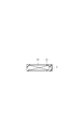
吸引ホルダ2の内部には半円形の仕切り壁4が形成されており、この仕切り壁4は吸引ホルダ2の軸線方向でみて中央よりも吸い口端8側に位置付けられている。仕切り壁4は吸引ホルダ2の内周面から突出して、その横断面の約半分に相当する領域を閉塞する。更に、吸引ホルダ2の内周面には一対のリブ6が形成されている。これらリブ6は吸引ホルダ2の長手軸線を挟んで配置され、仕切り壁4の内縁端から吸引ホルダ2の先端壁まで吸引ホルダ2の長手軸線と平行に延びている。 Referring to FIGS. 1 and 2, the non-heating type
A
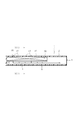
パウチ30及び仕切り壁4は、吸引ホルダ2の内部を上流区域10及び下流区域14に区分する。上流区域10は吸引ホルダ2の先端壁、仕切り壁4、パウチ30及び前記先端壁から前記仕切り壁4に亘る吸引ホルダ2の内周面によって囲まれており、下流区域14は吸引ホルダ2の先端壁から吸い口端8まで延びている。詳しくは、下流区域14は、上流区域10に沿って延び、半円形の横断面を有したフロント流路と、このフロント流路から吸い口端8まで延びる円形の横断面を有したリア流路とを有する。従って、上流区域10に面するパウチ30の露出面積は吸引ホルダ2の内径によって規定される横断面積よりも十分に広い。 On the
The
更に、上流区域10を形成する吸引ホルダ2の周壁には外気導入口12が分布して形成され、これら外気導入口12は上流区域10を吸引ホルダ2の外部と連通させている。それ故、吸引ホルダ2は外気導入口12から上流区域10及び下流区域14を経て吸い口端8に至る空気流路17を有する。 As shown in FIG. 3, the
Furthermore, outside
以下、香味吸引器の他の実施例について説明するが、前述の実施例の部材及び部位と同一の機能を有する部材及び部位には同一の参照符号を付し、その説明は省略する。
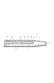
図4に示す実施例A(2)の香味吸引器1は、実施例A(1)の香味吸引器1と比べて外気導入口12の代わりに、少なくとも1個の外気導入口13を有する点のみで異なる。すなわち、実施例A(2)の香味吸引器1の場合、外気導入口13は、吸引ホルダ2の先端壁に形成され、吸引ホルダ2の外部と上流区域10内のスペース15とを連通させている。 Therefore, since the flavor component of tobacco is contained in the air sucked into the user, the user can effectively taste the flavor of tobacco.
Hereinafter, other embodiments of the flavor inhaler will be described, but the members and portions having the same functions as those of the above-described embodiments are denoted by the same reference numerals, and the description thereof will be omitted.
The
詳しくは、実施例Bの場合、吸引ホルダ2の先端壁は半円形の取出口16を有し、この取出口16は上流区域10を吸引ホルダ2の外部に開放する。一方、図7に示されるように、吸引ホルダ2は一対のリブ6の代わりに、その内周面に一対の溝22を有し、これら溝22は吸引ホルダ2の長手軸線を挟み、吸引ホルダ2の取出口16から仕切り壁4に亘って互いに平行に延びている。 The
Specifically, in the case of Example B, the tip wall of the
更に、図10に示されるように、パウチ30及び保持枠(18又は19)は、1つのカートリッジ44に置換することもでき、このカートリッジ44は通気性ケース46と、このケース46内に充填された粒状体47とを含む。具体的には、ケース46は保持枠18と同様な形状を有する保持枠48と、この保持枠48の開口を保持枠48の両面にて塞ぐ通気性シート49とによって形成されている。例えば、通気性シート49には不織布又はメッシュシートを使用することができる。 The holding
Further, as shown in FIG. 10, the
次に、図11に示す実施例C(1)の香味吸引器1の場合、吸引ホルダ2は開閉可能な構造を有する。具体的には、吸引ホルダ2は、ハーフパイプ24,26によって形成され、ハーフパイプ24は前述の仕切り壁4、上流区域10、下流区域14の一部及び外気導入口12を有し、ハーフパイプ26は下流区域14の残部を有する。 Furthermore, the holding frames 18, 19, 48 can further comprise a
Next, in the case of the
更に、ハーフパイプ24,26は吸引ホルダ2の先端にてセルフヒンジ28を介して互いに接続されている。そして、ハーフパイプ26に対してハーフパイプ24をセルフヒンジ28の回りに回動させることで、ハーフパイプ26は開閉される。図11中の2点鎖線は、開位置にあるハーフパイプ24を示す。 On the other hand,
Further, the
図13に示す実施例C(2)の香味吸引器1の吸引ホルダ2は、ホルダボディ32と、吸い口端8を形成する一体成形のマウスピース40とを含み、これらホルダボディ32及びマウスピース40は分離可能に接続されている。 Moreover, since the
The
また、ハーフパイプ33,34の後端面から凸部がそれぞれ突出されている。これら凸部は、ハーフパイプ33,34の開口縁が互い突き合わされたとき、即ち、ホルダボディ32が閉じられたとき、互いに協働して継手管部36を形成する。この継手管部36は下流区域14のフロント流路に連通する。なお、ハーフパイプ33の後端は前述した仕切り壁4を形成している。 Specifically, the
Further, convex portions protrude from the rear end surfaces of the
実施例C(2)の香味吸引器1であっても、前述の実施例の香味吸引器1と同様に、ユーザはたばこの香味を効果的に味わうことができる。また、実施例C(2)の場合、ホルダボディ32の継手管部36がマウスピース40の孔38に差し込まれているので、ハーフパイプ33,34に前述した凹部29a及び凸部29bは不要となる。 On the other hand, a
Even in the
図14及び図15に示す実施例C(3)の香味吸引器1は、前述した実施例C(1)と対比したとき、溝23がハーフパイプ24に形成されている点で相違する。詳しくは、溝23は長手軸線及びハーフパイプ26の対応する開口縁に向けてそれぞれ開口しており、この溝23には前述した保持枠18が嵌め込まれている。更に、この保持枠18と溝23とは互いに分離可能に連結されている。また、ハーフパイプ24,26とは凹部29a及び凸部29bのみで連結可能となっている。 In addition, in the case of the
The
なお、実施例C(2)の香味吸引器1についても同様に、溝23をハーフパイプ33に設けるようにしてもよい。 Therefore, the
In addition, the groove |
なお、香味発生源30は、一対のリブ6によらず、接着剤のみにより吸引ホルダ2内に支持されていてもよい。更に、実施例Cの香味吸引器1においても同様に、ハーフパイプ24、33の内面に香味発生源30が貼り付けられていてもよい。 Therefore, even in the
Note that the
この場合であっても、上流区域10に露出する粒状体47の充填領域は吸引ホルダ2の横断面より大きく確保されるので、ユーザに吸引される空気は粒状体から放出されたたばこの香味成分を良好に含むことができる。 Even in the
Even in this case, since the filling region of the
例えば、上記実施例では、吸い口端8は円形であるが、図20に示されるように、先細形状をなしていてもよい。
また、パウチ30は、紅茶の葉などの粒状体を含み、たばこの香味以外の香味を発生する香味発生源であってもよい。
また、吸引ホルダ2は、円筒形状としたがこれに限らずボックス型の吸引ホルダであってもよい。 The description of one embodiment of the present invention is finished above, but the present invention is not limited to the above embodiment, and various modifications can be made without departing from the technical idea of the present invention.
For example, in the above embodiment, the
Further, the
The
2 吸引ホルダ
4 仕切り壁
6 リブ
8 吸い口端
10 上流区域
12、13 外気導入口
14 下流区域
15 スペース
16 取出口
17 空気流路
18、19 保持枠
20 開口部
21 蓋
22、23 溝
24、26 ハーフパイプ
28 セルフヒンジ
29a,29b 凹部、凸部
30 パウチ(香味発生源)
32 ホルダボディ
33、34 ハーフパイプ
36 継手管部
38 孔
40 マウスピース
42 傾斜溝
44 カートリッジ
46 通気性ケース
47 粒状体
48 保持枠
49 通気性シート
50 吸引ホルダ DESCRIPTION OF
32
Claims (14)
- 中空の吸引ホルダであって、長手軸線、先端及び吸い口端としての後端を有する一方、その内部に前記先端側から取り入れた外気を前記吸い口端まで導く空気流路を規定する吸引ホルダと、
前記吸引ホルダ内に配置された香味発生源であって、通気性を有し且つ着火されずに前記空気流路に香味成分を放出する香味発生源と、
前記吸引ホルダ内にて前記香味発生源を支持する一方、前記空気流路を前記先端側の上流区域と前記吸い口端側の下流区域とに前記香味発生源によって仕切り且つ前記上流区域及び前記下流区域の少なくとも一方に面する前記香味発生源の露出面積を前記吸引ホルダの内周によって規定される横断面積よりも増加させる支持装置と
を備えたことを特徴とする非加熱型香味吸引器。 A hollow suction holder having a longitudinal axis, a front end, and a rear end as a suction end, and a suction holder for defining an air flow path that guides outside air taken from the front end side to the suction end in the inside thereof ,
A flavor generating source disposed in the suction holder, which has air permeability and emits a flavor component to the air flow path without being ignited, and
While supporting the flavor generation source in the suction holder, the air flow path is partitioned into the upstream area on the tip side and the downstream area on the suction end side by the flavor generation source, and the upstream area and the downstream area. A non-heated flavor inhaler comprising: a support device configured to increase an exposed area of the flavor generation source facing at least one of the areas to be greater than a cross-sectional area defined by an inner periphery of the suction holder. - 前記香味発生源は、前記吸引ホルダの前記先端から前記長手軸線に沿って延び、前記吸引ホルダの径方向に関して前記空気流路を仕切っていることを特徴とする請求項1に記載の非加熱型香味吸引器。 2. The non-heating type according to claim 1, wherein the flavor generation source extends along the longitudinal axis from the tip of the suction holder and partitions the air flow path with respect to a radial direction of the suction holder. Flavor aspirator.
- 前記上流区域は、前記吸引ホルダの周壁面又は前記先端壁の少なくとも一方に形成され、前記香味発生源に向けて外気を導く外気導入口を含むことを特徴とする請求項2に記載の非加熱型香味吸引器。 3. The non-heating unit according to claim 2, wherein the upstream section includes an outside air introduction port that is formed on at least one of a peripheral wall surface or the tip wall of the suction holder and guides outside air toward the flavor generation source. Type flavor aspirator.
- 前記吸引ホルダは、前記長手軸線を含む面にて互いに分離可能な一対のハーフパイプを含むことを特徴とする請求項3に記載の非加熱型香味吸引器。 The non-heated flavor inhaler according to claim 3, wherein the suction holder includes a pair of half pipes separable from each other on a surface including the longitudinal axis.
- 前記香味発生源と一方の前記ハーフパイプは一体的に結合されていることを特徴とする請求項4に記載の非加熱型香味吸引器。 The non-heated flavor inhaler according to claim 4, wherein the flavor generating source and the one half pipe are integrally coupled.
- 吸引ホルダは、前記一対のハーフパイプを開閉可能に結合するヒンジを更に含むことを特徴とする請求項4に記載の非加熱型香味吸引器。 The non-heated flavor inhaler according to claim 4, wherein the suction holder further includes a hinge that couples the pair of half pipes so as to be opened and closed.
- 前記吸引ホルダは、前記吸い口端側に位置する前記香味発生源の端位置を決定する仕切り壁を更に有し、
前記下流区域は、前記吸引ホルダの前記先端から前記上流区域に沿って前記仕切り壁まで延びるフロント流路と、このフロント流路から前記吸い口端まで延びるリア流路とを含むことを特徴とする請求項3記載の非加熱型香味吸引器。 The suction holder further includes a partition wall that determines an end position of the flavor generating source located on the mouth end side,
The downstream section includes a front flow path extending from the tip of the suction holder to the partition wall along the upstream section, and a rear flow path extending from the front flow path to the suction end. The non-heating type flavor inhaler of Claim 3. - 前記上流区域は、前記吸引ホルダの内面と前記香味発生源との間に確保されたスペースを含むことを特徴とする請求項7に記載の非加熱型香味吸引器。 The non-heating type flavor inhaler according to claim 7, wherein the upstream section includes a space secured between an inner surface of the suction holder and the flavor generation source.
- 前記吸引ホルダは、
前記先端から前記下流区域の前記フロント流路までを有するホルダボディと、
前記ホルダボディに分離可能に接続され、前記下流区域の前記リア流路を有するマウスピースと
を含むことを特徴とする請求項7に記載の非加熱型香味吸引器。 The suction holder is
A holder body having the tip to the front flow path in the downstream area;
The non-heated flavor inhaler according to claim 7, further comprising a mouthpiece detachably connected to the holder body and having the rear flow path in the downstream area. - 前記ホルダボディは、前記長手軸線を含む面にて互いに分離可能な一対のハーフパイプを含むことを特徴とする請求項9に記載の非加熱型香味吸引器。 The non-heated flavor inhaler according to claim 9, wherein the holder body includes a pair of half pipes separable from each other on a plane including the longitudinal axis.
- 前記香味発生源と一方のハーフパイプは一体的に結合されていること特徴とする請求項10に記載の非加熱型香味吸引器。 The non-heated flavor inhaler according to claim 10, wherein the flavor generating source and one half pipe are integrally coupled.
- 前記ホルダボディは、前記一対のハーフパイプを開閉可能に結合するヒンジを更に含むことを特徴とする請求項10に記載の非加熱型香味吸引器。 The non-heated flavor inhaler according to claim 10, wherein the holder body further includes a hinge that couples the pair of half pipes so as to be opened and closed.
- 前記香味発生源はパウチを含み、このパウチはたばこ葉を裁刻又は粉砕した粒状体と、この粒状体を包み込む通気性の包材とを有することを特徴とする請求項1に記載の非加熱型香味吸引器。 The non-heated product according to claim 1, wherein the flavor generating source includes a pouch, and the pouch has a granular material obtained by cutting or pulverizing tobacco leaves, and a breathable packaging material that wraps the granular material. Type flavor aspirator.
- 前記香味発生源は、前記パウチを保持する保持枠を更に含むことを特徴とする請求項13に記載の非加熱型香味吸引器。
The non-heating type flavor inhaler according to claim 13, wherein the flavor generation source further includes a holding frame for holding the pouch.
Priority Applications (10)
| Application Number | Priority Date | Filing Date | Title |
|---|---|---|---|
| CA2752577A CA2752577C (en) | 2009-02-23 | 2010-02-17 | Non-heating flavor inhaler |
| ES10743786.5T ES2455967T3 (en) | 2009-02-23 | 2010-02-17 | Unheated aroma inhaler |
| JP2011500634A JP5388241B2 (en) | 2009-02-23 | 2010-02-17 | Non-heated flavor aspirator |
| KR1020117021372A KR101347937B1 (en) | 2009-02-23 | 2010-02-17 | Non-heating type flavor inhaler |
| UAA201111265A UA97936C2 (en) | 2009-02-23 | 2010-02-17 | Non-heating type flavor inhaler |
| EP10743786.5A EP2399638B1 (en) | 2009-02-23 | 2010-02-17 | Non-heating type flavor inhaler |
| CN201080017225.8A CN102405074B (en) | 2009-02-23 | 2010-02-17 | Non-heating type flavor inhaler |
| RU2011138949/12A RU2011138949A (en) | 2009-02-23 | 2010-02-17 | NON-HEATING FRAGRANCE INHALATION DEVICE |
| US13/214,861 US8646462B2 (en) | 2009-02-23 | 2011-08-22 | Non-heating flavor inhaler |
| HK12105279.7A HK1164756A1 (en) | 2009-02-23 | 2012-05-30 | Non-heating type flavor inhaler |
Applications Claiming Priority (2)
| Application Number | Priority Date | Filing Date | Title |
|---|---|---|---|
| JP2009-039381 | 2009-02-23 | ||
| JP2009039381 | 2009-02-23 |
Related Child Applications (1)
| Application Number | Title | Priority Date | Filing Date |
|---|---|---|---|
| US13/214,861 Continuation US8646462B2 (en) | 2009-02-23 | 2011-08-22 | Non-heating flavor inhaler |
Publications (1)
| Publication Number | Publication Date |
|---|---|
| WO2010095660A1 true WO2010095660A1 (en) | 2010-08-26 |
Family
ID=42633940
Family Applications (1)
| Application Number | Title | Priority Date | Filing Date |
|---|---|---|---|
| PCT/JP2010/052370 WO2010095660A1 (en) | 2009-02-23 | 2010-02-17 | Non-heating type flavor inhaler |
Country Status (13)
| Country | Link |
|---|---|
| US (1) | US8646462B2 (en) |
| EP (1) | EP2399638B1 (en) |
| JP (1) | JP5388241B2 (en) |
| KR (1) | KR101347937B1 (en) |
| CN (1) | CN102405074B (en) |
| CA (1) | CA2752577C (en) |
| ES (1) | ES2455967T3 (en) |
| HK (1) | HK1164756A1 (en) |
| MY (1) | MY152937A (en) |
| RU (2) | RU2556525C2 (en) |
| TW (1) | TWI415639B (en) |
| UA (1) | UA97936C2 (en) |
| WO (1) | WO2010095660A1 (en) |
Cited By (17)
| Publication number | Priority date | Publication date | Assignee | Title |
|---|---|---|---|---|
| WO2011109848A1 (en) | 2010-03-10 | 2011-09-15 | Helmut Buchberger | Inhaler component |
| WO2012026481A1 (en) * | 2010-08-24 | 2012-03-01 | 日本たばこ産業株式会社 | Non-heating type apparatus for inhaling flavors and method for manufacturing flavor cartridge |
| WO2013111320A1 (en) | 2012-01-27 | 2013-08-01 | 日本たばこ産業株式会社 | Flavour cartridge and non-heating type flavour inhaler |
| WO2013122054A1 (en) * | 2012-02-13 | 2013-08-22 | 日本たばこ産業株式会社 | Non-heated flavor suction device, intermediate product thereof, blank and tubular piece-forming method |
| WO2013137084A1 (en) * | 2012-03-16 | 2013-09-19 | 日本たばこ産業株式会社 | Non-heating flavor inhaler |
| WO2014021310A1 (en) * | 2012-08-03 | 2014-02-06 | 日本たばこ産業株式会社 | Non-heated flavor inhaler |
| WO2014038484A1 (en) * | 2012-09-07 | 2014-03-13 | 日本たばこ産業株式会社 | Flavor inhaler package |
| WO2014061477A1 (en) * | 2012-10-18 | 2014-04-24 | 日本たばこ産業株式会社 | Non-combustion-type flavor inhaler |
| WO2014104078A1 (en) * | 2012-12-28 | 2014-07-03 | 日本たばこ産業株式会社 | Flavor source for non-combustion inhalation-type tobacco product, and non-combustion inhalation-type tobacco product |
| WO2014109238A1 (en) * | 2013-01-10 | 2014-07-17 | 日本たばこ産業株式会社 | Non-combustion type flavor inhalation device |
| WO2014156537A1 (en) * | 2013-03-28 | 2014-10-02 | 日本たばこ産業株式会社 | Non-heating-type flavor inhaler |
| WO2015049793A1 (en) * | 2013-10-04 | 2015-04-09 | 日本たばこ産業株式会社 | Non-heating type flavor aspirator manufacturing device and manufacturing method |
| WO2016075749A1 (en) * | 2014-11-10 | 2016-05-19 | 日本たばこ産業株式会社 | Cartridge and non-combusting flavor inhaler |
| WO2018037562A1 (en) * | 2016-08-26 | 2018-03-01 | 日本たばこ産業株式会社 | Non-combustion flavor inhaler |
| JP2018520834A (en) * | 2015-07-20 | 2018-08-02 | メディカル、ディベロップメンツ、インターナショナル、リミテッドMedical Developments International Limited | Inhaler device for inhalable liquid |
| US10278427B2 (en) | 2014-08-13 | 2019-05-07 | Batmark Limited | Aerosol delivery device and method utilizing a flavoring reservoir |
| US11026449B2 (en) | 2015-04-07 | 2021-06-08 | Philip Morris Products S.A. | Sachet of aerosol-forming substrate, method of manufacturing same, and aerosol-generating device for use with sachet |
Families Citing this family (59)
| Publication number | Priority date | Publication date | Assignee | Title |
|---|---|---|---|---|
| US20160345631A1 (en) | 2005-07-19 | 2016-12-01 | James Monsees | Portable devices for generating an inhalable vapor |
| AT507187B1 (en) | 2008-10-23 | 2010-03-15 | Helmut Dr Buchberger | INHALER |
| US9095175B2 (en) | 2010-05-15 | 2015-08-04 | R. J. Reynolds Tobacco Company | Data logging personal vaporizing inhaler |
| US8757147B2 (en) | 2010-05-15 | 2014-06-24 | Minusa Holdings Llc | Personal vaporizing inhaler with internal light source |
| US10136672B2 (en) | 2010-05-15 | 2018-11-27 | Rai Strategic Holdings, Inc. | Solderless directly written heating elements |
| US10159278B2 (en) | 2010-05-15 | 2018-12-25 | Rai Strategic Holdings, Inc. | Assembly directed airflow |
| US9743691B2 (en) | 2010-05-15 | 2017-08-29 | Rai Strategic Holdings, Inc. | Vaporizer configuration, control, and reporting |
| US9259035B2 (en) | 2010-05-15 | 2016-02-16 | R. J. Reynolds Tobacco Company | Solderless personal vaporizing inhaler |
| US9999250B2 (en) | 2010-05-15 | 2018-06-19 | Rai Strategic Holdings, Inc. | Vaporizer related systems, methods, and apparatus |
| US9861772B2 (en) | 2010-05-15 | 2018-01-09 | Rai Strategic Holdings, Inc. | Personal vaporizing inhaler cartridge |
| HUE026804T2 (en) | 2011-02-11 | 2016-07-28 | Batmark Ltd | Inhaler component |
| AT510837B1 (en) | 2011-07-27 | 2012-07-15 | Helmut Dr Buchberger | INHALATORKOMPONENTE |
| RU2595971C2 (en) | 2011-09-06 | 2016-08-27 | Бритиш Америкэн Тобэкко (Инвестментс) Лимитед | Heating smoking material |
| CA3162870A1 (en) | 2011-09-06 | 2013-03-14 | Nicoventures Trading Limited | Heating smokable material |
| AT511344B1 (en) | 2011-10-21 | 2012-11-15 | Helmut Dr Buchberger | INHALATORKOMPONENTE |
| GB201207039D0 (en) | 2012-04-23 | 2012-06-06 | British American Tobacco Co | Heating smokeable material |
| GB2504076A (en) | 2012-07-16 | 2014-01-22 | Nicoventures Holdings Ltd | Electronic smoking device |
| US10279934B2 (en) | 2013-03-15 | 2019-05-07 | Juul Labs, Inc. | Fillable vaporizer cartridge and method of filling |
| US9723876B2 (en) * | 2013-03-15 | 2017-08-08 | Altria Client Services Llc | Electronic smoking article |
| GB2513637A (en) | 2013-05-02 | 2014-11-05 | Nicoventures Holdings Ltd | Electronic cigarette |
| GB2513639A (en) | 2013-05-02 | 2014-11-05 | Nicoventures Holdings Ltd | Electronic cigarette |
| GB2513638A (en) | 2013-05-02 | 2014-11-05 | Nicoventures Holdings Ltd | Electronic cigarette |
| GB2514893B (en) | 2013-06-04 | 2017-12-06 | Nicoventures Holdings Ltd | Container |
| US20150020822A1 (en) * | 2013-07-19 | 2015-01-22 | Altria Client Services Inc. | Electronic smoking article |
| ZA201306282B (en) * | 2013-08-21 | 2014-04-30 | Darren James Alken | A device for curring addictive behaviour |
| US10058129B2 (en) | 2013-12-23 | 2018-08-28 | Juul Labs, Inc. | Vaporization device systems and methods |
| US10159282B2 (en) | 2013-12-23 | 2018-12-25 | Juul Labs, Inc. | Cartridge for use with a vaporizer device |
| USD842536S1 (en) | 2016-07-28 | 2019-03-05 | Juul Labs, Inc. | Vaporizer cartridge |
| US20160366947A1 (en) | 2013-12-23 | 2016-12-22 | James Monsees | Vaporizer apparatus |
| USD825102S1 (en) | 2016-07-28 | 2018-08-07 | Juul Labs, Inc. | Vaporizer device with cartridge |
| PL3498115T3 (en) | 2013-12-23 | 2021-12-20 | Juul Labs International Inc. | Vaporization device systems |
| US10076139B2 (en) | 2013-12-23 | 2018-09-18 | Juul Labs, Inc. | Vaporizer apparatus |
| GB201407426D0 (en) | 2014-04-28 | 2014-06-11 | Batmark Ltd | Aerosol forming component |
| WO2015166565A1 (en) * | 2014-04-30 | 2015-11-05 | 日本たばこ産業株式会社 | Production method for carbon heat source |
| US11478021B2 (en) * | 2014-05-16 | 2022-10-25 | Juul Labs, Inc. | Systems and methods for aerosolizing a vaporizable material |
| GB2528673B (en) | 2014-07-25 | 2020-07-01 | Nicoventures Holdings Ltd | Aerosol provision system |
| WO2016075747A1 (en) * | 2014-11-10 | 2016-05-19 | 日本たばこ産業株式会社 | Non-combusting flavor inhaler and package |
| CN112155255A (en) | 2014-12-05 | 2021-01-01 | 尤尔实验室有限公司 | Corrective dose control |
| GB2533135B (en) | 2014-12-11 | 2020-11-11 | Nicoventures Holdings Ltd | Aerosol provision systems |
| GB201511349D0 (en) | 2015-06-29 | 2015-08-12 | Nicoventures Holdings Ltd | Electronic aerosol provision systems |
| WO2017011868A1 (en) * | 2015-07-20 | 2017-01-26 | Medical Developments International Limited | Inhaler device for inhalable liquids |
| KR102574315B1 (en) | 2015-07-20 | 2023-09-05 | 메디컬 디벨롭먼츠 인터네셔널 리미티드 | Inhaler device for inhalable liquids |
| US20170055584A1 (en) | 2015-08-31 | 2017-03-02 | British American Tobacco (Investments) Limited | Article for use with apparatus for heating smokable material |
| US11924930B2 (en) | 2015-08-31 | 2024-03-05 | Nicoventures Trading Limited | Article for use with apparatus for heating smokable material |
| IL309606A (en) * | 2016-01-11 | 2024-02-01 | Syqe Medical Ltd | Personal vaporizing device |
| MX2018009703A (en) | 2016-02-11 | 2019-07-08 | Juul Labs Inc | Securely attaching cartridges for vaporizer devices. |
| DE202017007467U1 (en) | 2016-02-11 | 2021-12-08 | Juul Labs, Inc. | Fillable vaporizer cartridge |
| US10405582B2 (en) | 2016-03-10 | 2019-09-10 | Pax Labs, Inc. | Vaporization device with lip sensing |
| RU2708249C1 (en) | 2016-04-27 | 2019-12-05 | Никовенчерс Холдингз Лимитед | Aerosol formation electronic system and evaporator for such system |
| USD849996S1 (en) | 2016-06-16 | 2019-05-28 | Pax Labs, Inc. | Vaporizer cartridge |
| USD848057S1 (en) | 2016-06-23 | 2019-05-07 | Pax Labs, Inc. | Lid for a vaporizer |
| USD851830S1 (en) | 2016-06-23 | 2019-06-18 | Pax Labs, Inc. | Combined vaporizer tamp and pick tool |
| USD836541S1 (en) | 2016-06-23 | 2018-12-25 | Pax Labs, Inc. | Charging device |
| UA125699C2 (en) * | 2016-12-16 | 2022-05-18 | Кт & Г Корпорейшон | Aerosol generation method and apparatus |
| WO2018146738A1 (en) * | 2017-02-08 | 2018-08-16 | 日本たばこ産業株式会社 | Cartridge and inhaler |
| WO2018146736A1 (en) * | 2017-02-08 | 2018-08-16 | 日本たばこ産業株式会社 | Cartridge and inhaler |
| GB201707805D0 (en) * | 2017-05-16 | 2017-06-28 | Nicoventures Holdings Ltd | Atomiser for vapour provision device |
| USD887632S1 (en) | 2017-09-14 | 2020-06-16 | Pax Labs, Inc. | Vaporizer cartridge |
| MX2020012804A (en) | 2018-05-29 | 2021-03-25 | Juul Labs Inc | Vaporizer device with cartridge. |
Citations (5)
| Publication number | Priority date | Publication date | Assignee | Title |
|---|---|---|---|---|
| US3320953A (en) * | 1964-08-06 | 1967-05-23 | Rindner Sheperd | Mouth inhaler simulating smoking device |
| DE3639667A1 (en) * | 1986-11-20 | 1988-06-01 | Michael Schelowsky | Inhalation cartridge for stimulating and medicinal herbs to be inserted and exchanged in a special pipe head |
| JPH022331A (en) | 1988-03-30 | 1990-01-08 | Kowa Display:Kk | Smokeless tobacco |
| JPH02171174A (en) * | 1988-10-19 | 1990-07-02 | Burger Soehne Ag Burg | Camouflaging device for smoking |
| JP3137445U (en) * | 2007-09-13 | 2007-11-22 | 株式会社フリーサイエンス | Health aids for smoking cessation |
Family Cites Families (13)
| Publication number | Priority date | Publication date | Assignee | Title |
|---|---|---|---|---|
| GB645517A (en) * | 1948-10-11 | 1950-11-01 | Hardy Saabor | Improvements in or relating to imitation cigarettes |
| US4284089A (en) * | 1978-10-02 | 1981-08-18 | Ray Jon P | Simulated smoking device |
| US5159940A (en) * | 1988-07-22 | 1992-11-03 | Philip Morris Incorporated | Smoking article |
| JPH0264166A (en) | 1988-08-30 | 1990-03-05 | Pentel Kk | Deculstering coating |
| JPH11178562A (en) * | 1997-12-19 | 1999-07-06 | Japan Tobacco Inc | Noncombustible-type flavor-emissive article |
| GB2380410B (en) * | 2001-10-05 | 2003-11-19 | Alchemy Healthcare Ltd | Apparatus for the nasal or oral delivery of a medicament |
| CN104397869B (en) * | 2003-11-07 | 2016-06-08 | 美国无烟烟草有限责任公司 | Tobacco compositions |
| EP1711220A1 (en) | 2004-01-16 | 2006-10-18 | Biodel, Inc. | Sublingual drug delivery device |
| RU53116U1 (en) | 2005-11-24 | 2006-05-10 | Румянцев Валентин Павлович | CASE FOR GLASSES AND WRITTEN ACCESSORIES |
| US7810507B2 (en) * | 2006-02-10 | 2010-10-12 | R. J. Reynolds Tobacco Company | Smokeless tobacco composition |
| US20080302682A1 (en) | 2007-06-11 | 2008-12-11 | Radi Medical Biodegradable Ab | Pouch for tobacco or tobacco substitute |
| RU72821U1 (en) * | 2007-06-15 | 2008-05-10 | Александр Васильевич Когут | SMOKLESS SMOKING PRODUCT (OPTIONS) |
| UA26623U (en) * | 2007-06-19 | 2007-09-25 | Ltd Liability Company Yug Neft | Method to increase productivity of oil, gas and gas-condensate well |
-
2010
- 2010-02-17 KR KR1020117021372A patent/KR101347937B1/en active IP Right Grant
- 2010-02-17 ES ES10743786.5T patent/ES2455967T3/en active Active
- 2010-02-17 RU RU2013146669/12A patent/RU2556525C2/en active
- 2010-02-17 WO PCT/JP2010/052370 patent/WO2010095660A1/en active Application Filing
- 2010-02-17 RU RU2011138949/12A patent/RU2011138949A/en unknown
- 2010-02-17 MY MYPI2011003943 patent/MY152937A/en unknown
- 2010-02-17 CA CA2752577A patent/CA2752577C/en active Active
- 2010-02-17 EP EP10743786.5A patent/EP2399638B1/en active Active
- 2010-02-17 JP JP2011500634A patent/JP5388241B2/en active Active
- 2010-02-17 UA UAA201111265A patent/UA97936C2/en unknown
- 2010-02-17 CN CN201080017225.8A patent/CN102405074B/en not_active Expired - Fee Related
- 2010-02-23 TW TW099105128A patent/TWI415639B/en not_active IP Right Cessation
-
2011
- 2011-08-22 US US13/214,861 patent/US8646462B2/en active Active
-
2012
- 2012-05-30 HK HK12105279.7A patent/HK1164756A1/en not_active IP Right Cessation
Patent Citations (5)
| Publication number | Priority date | Publication date | Assignee | Title |
|---|---|---|---|---|
| US3320953A (en) * | 1964-08-06 | 1967-05-23 | Rindner Sheperd | Mouth inhaler simulating smoking device |
| DE3639667A1 (en) * | 1986-11-20 | 1988-06-01 | Michael Schelowsky | Inhalation cartridge for stimulating and medicinal herbs to be inserted and exchanged in a special pipe head |
| JPH022331A (en) | 1988-03-30 | 1990-01-08 | Kowa Display:Kk | Smokeless tobacco |
| JPH02171174A (en) * | 1988-10-19 | 1990-07-02 | Burger Soehne Ag Burg | Camouflaging device for smoking |
| JP3137445U (en) * | 2007-09-13 | 2007-11-22 | 株式会社フリーサイエンス | Health aids for smoking cessation |
Non-Patent Citations (1)
| Title |
|---|
| See also references of EP2399638A4 |
Cited By (47)
| Publication number | Priority date | Publication date | Assignee | Title |
|---|---|---|---|---|
| US9554595B2 (en) | 2010-03-10 | 2017-01-31 | Batmark Limited | Inhaler component |
| US10701969B2 (en) | 2010-03-10 | 2020-07-07 | Batmark Limited | Inhaler component |
| WO2011109848A1 (en) | 2010-03-10 | 2011-09-15 | Helmut Buchberger | Inhaler component |
| US9682204B2 (en) | 2010-08-24 | 2017-06-20 | Japan Tobacco Inc. | Non-heating type flavor inhalator and method of manufacturing flavor cartridge |
| JP5443606B2 (en) * | 2010-08-24 | 2014-03-19 | 日本たばこ産業株式会社 | Non-heating type flavor suction device and method for producing flavor cartridge |
| US10668233B2 (en) | 2010-08-24 | 2020-06-02 | Japan Tobacco Inc. | Non-heating type flavor inhalator and method of manufacturing flavor cartridge |
| WO2012026481A1 (en) * | 2010-08-24 | 2012-03-01 | 日本たばこ産業株式会社 | Non-heating type apparatus for inhaling flavors and method for manufacturing flavor cartridge |
| KR101389143B1 (en) | 2010-08-24 | 2014-04-24 | 니뽄 다바코 산교 가부시키가이샤 | Non-heating type apparatus for inhaling flavors and method for manufacturing flavor cartridge |
| WO2013111320A1 (en) | 2012-01-27 | 2013-08-01 | 日本たばこ産業株式会社 | Flavour cartridge and non-heating type flavour inhaler |
| WO2013122054A1 (en) * | 2012-02-13 | 2013-08-22 | 日本たばこ産業株式会社 | Non-heated flavor suction device, intermediate product thereof, blank and tubular piece-forming method |
| WO2013137084A1 (en) * | 2012-03-16 | 2013-09-19 | 日本たばこ産業株式会社 | Non-heating flavor inhaler |
| JP5933007B2 (en) * | 2012-08-03 | 2016-06-08 | 日本たばこ産業株式会社 | Non-heated flavor aspirator |
| WO2014021310A1 (en) * | 2012-08-03 | 2014-02-06 | 日本たばこ産業株式会社 | Non-heated flavor inhaler |
| JPWO2014021310A1 (en) * | 2012-08-03 | 2016-07-21 | 日本たばこ産業株式会社 | Non-heated flavor aspirator |
| WO2014038484A1 (en) * | 2012-09-07 | 2014-03-13 | 日本たばこ産業株式会社 | Flavor inhaler package |
| JP5824159B2 (en) * | 2012-09-07 | 2015-11-25 | 日本たばこ産業株式会社 | Flavor aspirator package |
| US10420372B2 (en) | 2012-10-18 | 2019-09-24 | Japan Tobacco Inc. | Non-burning type flavor inhaler |
| WO2014061477A1 (en) * | 2012-10-18 | 2014-04-24 | 日本たばこ産業株式会社 | Non-combustion-type flavor inhaler |
| JP5895062B2 (en) * | 2012-10-18 | 2016-03-30 | 日本たばこ産業株式会社 | Non-burning flavor inhaler |
| JPWO2014061477A1 (en) * | 2012-10-18 | 2016-09-05 | 日本たばこ産業株式会社 | Non-burning flavor inhaler |
| JPWO2014104078A1 (en) * | 2012-12-28 | 2017-01-12 | 日本たばこ産業株式会社 | Non-combustion suction type tobacco product flavor source and non-combustion suction type tobacco product |
| JP6014684B2 (en) * | 2012-12-28 | 2016-10-25 | 日本たばこ産業株式会社 | Non-combustion suction type tobacco product flavor source and non-combustion suction type tobacco product |
| WO2014104078A1 (en) * | 2012-12-28 | 2014-07-03 | 日本たばこ産業株式会社 | Flavor source for non-combustion inhalation-type tobacco product, and non-combustion inhalation-type tobacco product |
| JP5895067B2 (en) * | 2013-01-10 | 2016-03-30 | 日本たばこ産業株式会社 | Non-burning flavor suction tool |
| WO2014109238A1 (en) * | 2013-01-10 | 2014-07-17 | 日本たばこ産業株式会社 | Non-combustion type flavor inhalation device |
| WO2014156537A1 (en) * | 2013-03-28 | 2014-10-02 | 日本たばこ産業株式会社 | Non-heating-type flavor inhaler |
| WO2015049793A1 (en) * | 2013-10-04 | 2015-04-09 | 日本たばこ産業株式会社 | Non-heating type flavor aspirator manufacturing device and manufacturing method |
| US10278427B2 (en) | 2014-08-13 | 2019-05-07 | Batmark Limited | Aerosol delivery device and method utilizing a flavoring reservoir |
| EP3545998A1 (en) | 2014-08-13 | 2019-10-02 | BATMark Limited | Aerosol delivery device |
| EP3967161A1 (en) | 2014-08-13 | 2022-03-16 | Nicoventures Trading Limited | Aerosol delivery devices, consumables and assembly |
| EP3967160A1 (en) | 2014-08-13 | 2022-03-16 | Nicoventures Trading Limited | Aerosol delivery device |
| US11116919B2 (en) | 2014-08-13 | 2021-09-14 | Batmark Limited | Aerosol delivery device and method utilizing a flavoring reservoir |
| US10674771B2 (en) | 2014-08-13 | 2020-06-09 | Batmark Limited | Aerosol delivery device and method utilizing a flavoring reservoir |
| US11865248B2 (en) | 2014-08-13 | 2024-01-09 | Nicoventures Trading Limited | Aerosol delivery device and method utilizing a flavoring reservoir |
| EP4292458A2 (en) | 2014-08-13 | 2023-12-20 | Nicoventures Trading Limited | Aerosol delivery device |
| US10653179B2 (en) | 2014-11-10 | 2020-05-19 | Japan Tobacco Inc. | Cartridge and non-burning type flavor inhaler |
| KR20170078765A (en) * | 2014-11-10 | 2017-07-07 | 니뽄 다바코 산교 가부시키가이샤 | Cartridge and non-combusting flavor inhaler |
| EA032720B1 (en) * | 2014-11-10 | 2019-07-31 | Джапан Тобакко Инк. | Cartridge and non-combusting flavor inhaler |
| JPWO2016075749A1 (en) * | 2014-11-10 | 2017-06-08 | 日本たばこ産業株式会社 | Cartridge and non-combustion flavor inhaler |
| WO2016075749A1 (en) * | 2014-11-10 | 2016-05-19 | 日本たばこ産業株式会社 | Cartridge and non-combusting flavor inhaler |
| KR101939004B1 (en) * | 2014-11-10 | 2019-01-15 | 니뽄 다바코 산교 가부시키가이샤 | Cartridge and non-combusting flavor inhaler |
| US11026449B2 (en) | 2015-04-07 | 2021-06-08 | Philip Morris Products S.A. | Sachet of aerosol-forming substrate, method of manufacturing same, and aerosol-generating device for use with sachet |
| JP7043399B2 (en) | 2015-07-20 | 2022-03-29 | メディカル、ディベロップメンツ、インターナショナル、リミテッド | Inhaler device for inhalable liquids |
| JP2018520834A (en) * | 2015-07-20 | 2018-08-02 | メディカル、ディベロップメンツ、インターナショナル、リミテッドMedical Developments International Limited | Inhaler device for inhalable liquid |
| EA038384B1 (en) * | 2016-08-26 | 2021-08-19 | Джапан Тобакко Инк. | Non-combustion flavor inhaler |
| JPWO2018037562A1 (en) * | 2016-08-26 | 2019-04-04 | 日本たばこ産業株式会社 | Non-burning flavor inhaler |
| WO2018037562A1 (en) * | 2016-08-26 | 2018-03-01 | 日本たばこ産業株式会社 | Non-combustion flavor inhaler |
Also Published As
| Publication number | Publication date |
|---|---|
| TW201032740A (en) | 2010-09-16 |
| MY152937A (en) | 2014-12-15 |
| TWI415639B (en) | 2013-11-21 |
| RU2011138949A (en) | 2013-03-27 |
| ES2455967T3 (en) | 2014-04-16 |
| RU2556525C2 (en) | 2015-07-10 |
| CA2752577A1 (en) | 2010-08-26 |
| KR20110117710A (en) | 2011-10-27 |
| CN102405074B (en) | 2014-08-13 |
| US8646462B2 (en) | 2014-02-11 |
| CN102405074A (en) | 2012-04-04 |
| RU2013146669A (en) | 2015-04-27 |
| EP2399638A1 (en) | 2011-12-28 |
| US20110290267A1 (en) | 2011-12-01 |
| HK1164756A1 (en) | 2012-09-28 |
| CA2752577C (en) | 2014-04-15 |
| JP5388241B2 (en) | 2014-01-15 |
| UA97936C2 (en) | 2012-03-26 |
| EP2399638A4 (en) | 2012-07-04 |
| KR101347937B1 (en) | 2014-01-07 |
| JPWO2010095660A1 (en) | 2012-08-30 |
| EP2399638B1 (en) | 2014-01-22 |
Similar Documents
| Publication | Publication Date | Title |
|---|---|---|
| JP5388241B2 (en) | Non-heated flavor aspirator | |
| ES2875825T3 (en) | Aerosol delivery device | |
| JP5443606B2 (en) | Non-heating type flavor suction device and method for producing flavor cartridge | |
| CN105142433B (en) | Getter device and inhalant equipment | |
| RU2626933C2 (en) | Inhalation device and component for inhalation device | |
| EP3277112B1 (en) | Cartridge, pouch and method of manufacture of pouch for use with apparatus for heating smokable material | |
| JP5737771B2 (en) | Flavor cartridge and non-heated flavor aspirator | |
| KR20160109073A (en) | Filter for electronic cigarrette | |
| RU2640712C2 (en) | Smoking product | |
| KR101768815B1 (en) | Smokeless tobacco and manufactured goods having the same | |
| JP7267423B2 (en) | flavor aspirator | |
| JP7267422B2 (en) | flavor aspirator | |
| KR20150143156A (en) | Smokeless tobacco and manufactured goods having the same | |
| RU2794459C2 (en) | Aerosol delivery device | |
| TW201330787A (en) | Flavor cartridge and non-heated flavor suction apparatus |
Legal Events
| Date | Code | Title | Description |
|---|---|---|---|
| WWE | Wipo information: entry into national phase |
Ref document number: 201080017225.8 Country of ref document: CN |
|
| 121 | Ep: the epo has been informed by wipo that ep was designated in this application |
Ref document number: 10743786 Country of ref document: EP Kind code of ref document: A1 |
|
| DPE1 | Request for preliminary examination filed after expiration of 19th month from priority date (pct application filed from 20040101) | ||
| WWE | Wipo information: entry into national phase |
Ref document number: 2011500634 Country of ref document: JP |
|
| WWE | Wipo information: entry into national phase |
Ref document number: 2752577 Country of ref document: CA |
|
| WWE | Wipo information: entry into national phase |
Ref document number: 2010743786 Country of ref document: EP |
|
| NENP | Non-entry into the national phase |
Ref country code: DE |
|
| ENP | Entry into the national phase |
Ref document number: 20117021372 Country of ref document: KR Kind code of ref document: A |
|
| WWE | Wipo information: entry into national phase |
Ref document number: A201111265 Country of ref document: UA |
|
| WWE | Wipo information: entry into national phase |
Ref document number: 2011138949 Country of ref document: RU |