WO2010095557A1 - Image processing device and method - Google Patents
Image processing device and method Download PDFInfo
- Publication number
- WO2010095557A1 WO2010095557A1 PCT/JP2010/052017 JP2010052017W WO2010095557A1 WO 2010095557 A1 WO2010095557 A1 WO 2010095557A1 JP 2010052017 W JP2010052017 W JP 2010052017W WO 2010095557 A1 WO2010095557 A1 WO 2010095557A1
- Authority
- WO
- WIPO (PCT)
- Prior art keywords
- image
- circuit
- motion compensated
- motion
- prediction
- Prior art date
Links
Images


Classifications
-
- H—ELECTRICITY
- H04—ELECTRIC COMMUNICATION TECHNIQUE
- H04N—PICTORIAL COMMUNICATION, e.g. TELEVISION
- H04N19/00—Methods or arrangements for coding, decoding, compressing or decompressing digital video signals
- H04N19/10—Methods or arrangements for coding, decoding, compressing or decompressing digital video signals using adaptive coding
- H04N19/102—Methods or arrangements for coding, decoding, compressing or decompressing digital video signals using adaptive coding characterised by the element, parameter or selection affected or controlled by the adaptive coding
- H04N19/103—Selection of coding mode or of prediction mode
- H04N19/105—Selection of the reference unit for prediction within a chosen coding or prediction mode, e.g. adaptive choice of position and number of pixels used for prediction
-
- H—ELECTRICITY
- H04—ELECTRIC COMMUNICATION TECHNIQUE
- H04N—PICTORIAL COMMUNICATION, e.g. TELEVISION
- H04N19/00—Methods or arrangements for coding, decoding, compressing or decompressing digital video signals
- H04N19/10—Methods or arrangements for coding, decoding, compressing or decompressing digital video signals using adaptive coding
- H04N19/102—Methods or arrangements for coding, decoding, compressing or decompressing digital video signals using adaptive coding characterised by the element, parameter or selection affected or controlled by the adaptive coding
- H04N19/103—Selection of coding mode or of prediction mode
- H04N19/107—Selection of coding mode or of prediction mode between spatial and temporal predictive coding, e.g. picture refresh
-
- H—ELECTRICITY
- H04—ELECTRIC COMMUNICATION TECHNIQUE
- H04N—PICTORIAL COMMUNICATION, e.g. TELEVISION
- H04N19/00—Methods or arrangements for coding, decoding, compressing or decompressing digital video signals
- H04N19/10—Methods or arrangements for coding, decoding, compressing or decompressing digital video signals using adaptive coding
- H04N19/102—Methods or arrangements for coding, decoding, compressing or decompressing digital video signals using adaptive coding characterised by the element, parameter or selection affected or controlled by the adaptive coding
- H04N19/103—Selection of coding mode or of prediction mode
- H04N19/109—Selection of coding mode or of prediction mode among a plurality of temporal predictive coding modes
-
- H—ELECTRICITY
- H04—ELECTRIC COMMUNICATION TECHNIQUE
- H04N—PICTORIAL COMMUNICATION, e.g. TELEVISION
- H04N19/00—Methods or arrangements for coding, decoding, compressing or decompressing digital video signals
- H04N19/10—Methods or arrangements for coding, decoding, compressing or decompressing digital video signals using adaptive coding
- H04N19/102—Methods or arrangements for coding, decoding, compressing or decompressing digital video signals using adaptive coding characterised by the element, parameter or selection affected or controlled by the adaptive coding
- H04N19/117—Filters, e.g. for pre-processing or post-processing
-
- H—ELECTRICITY
- H04—ELECTRIC COMMUNICATION TECHNIQUE
- H04N—PICTORIAL COMMUNICATION, e.g. TELEVISION
- H04N19/00—Methods or arrangements for coding, decoding, compressing or decompressing digital video signals
- H04N19/42—Methods or arrangements for coding, decoding, compressing or decompressing digital video signals characterised by implementation details or hardware specially adapted for video compression or decompression, e.g. dedicated software implementation
- H04N19/43—Hardware specially adapted for motion estimation or compensation
-
- H—ELECTRICITY
- H04—ELECTRIC COMMUNICATION TECHNIQUE
- H04N—PICTORIAL COMMUNICATION, e.g. TELEVISION
- H04N19/00—Methods or arrangements for coding, decoding, compressing or decompressing digital video signals
- H04N19/50—Methods or arrangements for coding, decoding, compressing or decompressing digital video signals using predictive coding
- H04N19/503—Methods or arrangements for coding, decoding, compressing or decompressing digital video signals using predictive coding involving temporal prediction
- H04N19/51—Motion estimation or motion compensation
- H04N19/573—Motion compensation with multiple frame prediction using two or more reference frames in a given prediction direction
-
- H—ELECTRICITY
- H04—ELECTRIC COMMUNICATION TECHNIQUE
- H04N—PICTORIAL COMMUNICATION, e.g. TELEVISION
- H04N19/00—Methods or arrangements for coding, decoding, compressing or decompressing digital video signals
- H04N19/50—Methods or arrangements for coding, decoding, compressing or decompressing digital video signals using predictive coding
- H04N19/503—Methods or arrangements for coding, decoding, compressing or decompressing digital video signals using predictive coding involving temporal prediction
- H04N19/51—Motion estimation or motion compensation
- H04N19/577—Motion compensation with bidirectional frame interpolation, i.e. using B-pictures
-
- H—ELECTRICITY
- H04—ELECTRIC COMMUNICATION TECHNIQUE
- H04N—PICTORIAL COMMUNICATION, e.g. TELEVISION
- H04N19/00—Methods or arrangements for coding, decoding, compressing or decompressing digital video signals
- H04N19/60—Methods or arrangements for coding, decoding, compressing or decompressing digital video signals using transform coding
- H04N19/61—Methods or arrangements for coding, decoding, compressing or decompressing digital video signals using transform coding in combination with predictive coding
-
- H—ELECTRICITY
- H04—ELECTRIC COMMUNICATION TECHNIQUE
- H04N—PICTORIAL COMMUNICATION, e.g. TELEVISION
- H04N19/00—Methods or arrangements for coding, decoding, compressing or decompressing digital video signals
- H04N19/80—Details of filtering operations specially adapted for video compression, e.g. for pixel interpolation
- H04N19/82—Details of filtering operations specially adapted for video compression, e.g. for pixel interpolation involving filtering within a prediction loop
Definitions
- the present invention relates to an image processing apparatus and method, and more particularly to an image processing apparatus and method capable of generating a highly accurate predicted image without increasing the processing load.
- unidirectional correlation or bidirectional prediction is used when generating an inter frame which is a frame to be subjected to inter prediction (inter prediction) using correlation in the time direction.
- Inter-frame prediction is to generate a prediction image based on frames at different times.
- FIG. 1 is a diagram illustrating an example of unidirectional prediction.
- a coded frame P0 which is a frame of the current time to be coded
- coding at a time past or future in time from the current time has been done
- Motion compensation is performed using the frame of (1) as a reference frame.
- Reference frame information and a motion vector are respectively used as information specifying a reference frame and information specifying a position of a reference destination of the reference frame, and the information is transmitted from the encoding side to the decoding side.
- the number of reference frames is not limited to one.
- FIG. 1 when two frames are referred to as reference frames R0 and R1 in order of time closer to coding frame P0, the pixel value of any pixel of reference frame R0 or R1 is within coding frame P0.
- the pixel values of any macroblock of can be predicted.
- the frames shown inside each frame of FIG. 1 represent macroblocks. Assuming that the macroblock of the encoded frame P0 to be predicted is the macroblock MBP0, the macroblock of the reference frame R0 corresponding to the macroblock MBP0 is the macroblock MBR0 specified by the motion vector MV0. Also, the macroblock of the reference frame R1 is the macroblock MBR1 specified by the motion vector MV1.
- the pixel value of any motion compensated image is predicted in unidirectional prediction.
- the predicted image Pred (i, j) is expressed by the following equation (1) because it is used as a pixel value of. (i, j) represents the relative position of the pixel in the macro block, and 0 ⁇ i ⁇ 16 and 0 ⁇ j ⁇ 16.
- ” represents taking one of MC0 (i, j) and MC1 (i, j).
- FIG. 2 is a diagram illustrating an example of bidirectional prediction.
- a coded frame B0 which is a frame of the current time to be coded
- coding in the past and future times in time is performed from the current time.
- Motion compensation is performed using the frame of (1) as a reference frame. It is possible to reduce the amount of codes by encoding a plurality of encoded frames as reference frames and using the correlation with them to encode the residual between the predicted image and the actual image. In H.264, it is also possible to use a plurality of past frames and a plurality of future frames as reference frames.
- a coding frame is generated from pixel values of arbitrary pixels of the reference frames L0 and L1.
- the pixel values of any macroblock in B0 can be predicted.
- the macroblock of the reference frame L0 corresponding to the macroblock MBB0 of the coding frame B0 is a macroblock MBL0 specified by the motion vector MV0.
- the macroblock of the reference frame L1 corresponding to the macroblock MBB0 of the encoded frame B0 is a macroblock MBL1 specified by the motion vector MV1.
- the pixel value Pred (i, j) of the predicted image Pred (i, j) is expressed by the following equation (2) It is determined as their average value as shown in.
- the accuracy of the predicted image is improved by increasing the accuracy of the motion vector or by reducing the size of the macro block, and the residual with the actual image is reduced. By doing this, the coding efficiency is improved.
- the prediction residual can be probabilistically viewed using the average of the pixel values of the pixels of the reference frame that is close in time as the pixel value of the pixels of the predicted image. I was able to achieve stable reduction.
- Non-Patent Document 1 there has been considered a method in which correlation in the temporal direction is converted into spatial resolution and used by motion compensation and FIR filtering of pixel values (see, for example, Non-Patent Document 1).
- Non-Patent Document 1 correlation in the time direction is used for the resolution enhancement process on an input image sequence. Specifically, the difference information of the motion predicted / compensated image is calculated between the current image and the past image, and the high frequency component included in the input image is restored by feedback to the current image of interest. .
- temporal low-pass filter processing is performed by using the average value of pixel values of two reference frames as the pixel value of the encoded frame.
- the ingredients are lost.
- the image obtained by decoding loses high frequency components, and the sense of resolution is degraded.
- Non-Patent Document 2 Furthermore, by filtering and using information of two or more reference frames according to the method of [Non-Patent Document 2], prediction can be performed with higher accuracy than conventional bidirectional prediction, In this case, it is necessary to transmit motion vector information for each of two or more reference frames to the decoder. That is, a large amount of control information is required to improve prediction accuracy, which may not be effective from the viewpoint of coding efficiency.
- the present invention has been made in view of such a situation, and the amount of code for a motion vector necessary for bi-directional prediction and multiple image reference can be reduced to reduce the control information with high accuracy. It makes it possible to generate a predicted image.
- One aspect of the present invention is a decoding unit that decodes a coded image, a generation unit that adds the image decoded by the decoding unit and a predicted image, and generates a decoded image, and the generation unit generates the decoded image.
- Motion compensation is performed using a motion vector of the encoded image using a frame composed of the decoded image as a reference frame, and a motion compensated image corresponding to the predicted image is extracted from the reference frame A part corresponding to or approximate to the motion-compensated image extracted by the first extraction means in a reference frame different from the reference frame from which the motion-compensated image is extracted, and the motion information corresponding to the predicted image
- a second extraction unit for extracting from the reference frame as a compensated image, the motion compensated image extracted by the first extraction unit, and Prediction image generation for generating the predicted image by performing filtering processing for compensating for a high frequency component using the correlation in the time direction included in the motion compensated image on the motion compensated image extracted by the extracting unit of
- An image processing apparatus comprising:
- the second extraction unit matches a part that matches or approximates the motion compensated image extracted by the first extraction unit using a predetermined cost function shared with the encoding device that encodes the image, It can be extracted from the reference frame as a motion compensated image corresponding to the predicted image.
- the cost function may be a function for obtaining a sum of absolute values of difference values of pixel values between the motion compensated image extracted by the first extraction unit and the processing target block of the reference frame.
- the cost function may be a function for obtaining a least square error of each pixel value between the motion compensated image extracted by the first extraction unit and the processing target block of the reference frame.
- the predicted image generation means is a first filter means for applying a low pass filter to a difference image between the motion compensated image extracted by the first extraction means and the motion compensated image extracted by the second extraction means And second filter means for applying a high-pass filter to the image obtained by applying a low-pass filter by said first filter means, and an image obtained by applying a low-pass filter by said first filter means And the image obtained by applying the high-pass filter by the second filter means to the motion compensated image extracted by the first extraction means and the motion extracted by the second extraction means And adding means for generating the predicted image by adding to any of the compensated images. That.
- the addition means is an image obtained by applying the low pass filter by the first filter means to the motion compensated image extracted from the frame one time before on the basis of the time of the predicted image; An image obtained by applying the high pass filter by the second filter means can be added.
- Bidirectional prediction is performed using a plurality of motion compensated images and unidirectional prediction is performed using a plurality of motion compensated images, and bidirectional prediction is performed using a plurality of motion compensated images to generate the predicted image Whether the predicted image is generated by unidirectional prediction by the unidirectional prediction unit or by bidirectional prediction by the bidirectional prediction unit is performed by the prediction unit and the identification flag included in the header of the encoded image
- the image processing apparatus may further include determination means for determining whether the image is to be generated by the filtering process by the predicted image generation means.
- One aspect of the present invention also decodes a coded image, adds the decoded image and a predicted image, generates a decoded image, and uses a frame consisting of the generated decoded image as a reference frame.
- Motion compensation is performed using a motion vector of the encoded image, a motion compensated image corresponding to the predicted image is extracted from the reference frame, and a reference frame different from the reference frame from which the motion compensated image is extracted A part that matches or approximates the extracted motion compensated image is extracted from the reference frame as a motion compensated image corresponding to the predicted image, and the motion compensation is performed on a plurality of extracted motion compensated images
- Another aspect of the present invention is based on encoding means for encoding an original image to be encoded and generating an encoded image, and a residual signal indicating a difference between the original image and the predicted image.
- Detection means for detecting a motion vector based on an image obtained by locally decoding the image and the original image, and the detection means using a frame consisting of the image obtained by locally decoding as a reference frame
- a first extraction unit that performs motion compensation using the motion vector detected by the motion detection unit and extracts a motion compensated image corresponding to the predicted image from the reference frame, and is different from the reference frame from which the motion compensated image is extracted
- a portion that matches or approximates to the motion compensated image extracted by the first extracting unit is used as the motion compensated image corresponding to the predicted image from the reference frame.
- an image processing apparatus comprising: generation means for generating the predicted image by performing filtering processing for compensating high frequency components using correlation of directions.
- the second extraction unit matches or approximates the motion compensated image extracted by the first extraction unit using a predetermined cost function shared with a decoding device that decodes the encoded image Can be extracted from the reference frame as a motion compensated image corresponding to the predicted image.
- the cost function may be a function for obtaining a sum of absolute values of difference values of pixel values between the motion compensated image extracted by the first extraction unit and the processing target block of the reference frame.
- the cost function may be a function for obtaining a least square error of each pixel value between the motion compensated image extracted by the first extraction unit and the processing target block of the reference frame.
- the generation means is a first filter means for applying a low pass filter to the motion compensation image extracted by the first extraction means and the differential image of the motion compensation image extracted by the second extraction means;
- a second filter that applies a high pass filter to an image obtained by applying a low pass filter by the first filter, an image obtained by applying a low pass filter by the first filter, and The image obtained by applying the high-pass filter by the second filter means, the motion-compensated image extracted by the first extraction means, and the motion-compensated image extracted by the second extraction means
- adding means for adding to any of them to generate the predicted image.
- the addition means is an image obtained by applying the low pass filter by the first filter means to the motion compensated image extracted from the frame one time before on the basis of the time of the predicted image; An image obtained by applying the high pass filter by the second filter means can be added.
- the encoding means identifies an identification flag identifying whether to generate a predicted image to be added to the image decoded by the decoding device by one-way prediction, bidirectional prediction, or the filtering process. , May be included in the header of the encoded image.
- Another aspect of the present invention is also to encode an original image which is an image to be encoded, generate an encoded image, and locally based on a residual signal indicating a difference between the original image and a predicted image.
- the motion vector is detected on the basis of the image obtained by decoding the image and the original image, and a motion is generated using the detected motion vector, using a frame consisting of the image obtained by Compensate, extract a motion compensated image corresponding to the predicted image from the reference frame, and match or approximate the extracted motion compensated image in a reference frame different from the reference frame from which the motion compensated image is extracted
- a part is extracted from the reference frame as a motion compensated image corresponding to the predicted image, and time directions included in the motion compensated image with respect to the plurality of extracted motion compensated images are extracted.
- a coded image is decoded, the decoded image and a predicted image are added, a decoded image is generated, and a frame consisting of the generated decoded image is used as a reference frame.
- Motion compensation is performed using the motion vector of the encoded image, and the motion compensated image corresponding to the predicted image is extracted from the reference frame, and the motion compensated image is extracted in the reference frame different from the extracted reference frame.
- the portion matching or approximating the motion compensated image is extracted from the reference frame as a motion compensated image corresponding to the predicted image, and the correlation in the time direction included in the motion compensated image is made to the extracted plurality of motion compensated images.
- a prediction image is generated by performing filtering processing to compensate for high frequency components to be used.
- an original image which is an image to be encoded is encoded to generate an encoded image, and a local signal is generated based on a residual signal indicating a difference between the original image and a predicted image.
- Motion vector is detected on the basis of the image obtained by decoding the image and the original image, and the motion compensation is performed using the detected motion vector with the frame consisting of the image obtained by the local decoding as the reference frame.
- the motion compensated image corresponding to the predicted image is extracted from the reference frame, and in the reference frame different from the reference frame from which the motion compensated image is extracted, a portion that matches or approximates the extracted motion compensated image is the predicted image
- a high frequency component is compensated for a plurality of extracted motion compensated images extracted from the reference frame as a corresponding motion compensated image using the correlation in the time direction included in the motion compensated image. By filtering process is performed, a prediction image is generated.
- a highly accurate predicted image can be generated without increasing the amount of transmission of motion vectors in a stream, and high encoding efficiency can be achieved.
- FIG. 3 is a diagram for explaining an outline of a predicted image generation method to which the present invention is applied.
- At least one motion vector (motion vector A) is transmitted in a bitstream to obtain a plurality of motion compensated images from a plurality of reference planes.
- FIG. 3 shows that two frames (N ⁇ 1) and (N ⁇ 2) are used as reference planes for motion compensation for decoding of frame N.
- a motion vector A for indicating coordinates in frame (N-1) is transmitted in a stream.
- the decoder obtains an image MC by this vector.
- the decoder performs motion prediction. That is, an image MC 'having a value close to that of the image MC is searched from the frame (N-2).
- a search method for example, a search algorithm, a search range, a cost function, etc. is arbitrary as long as it is shared in advance by the encoder and the decoder. By sharing these with the encoder and the decoder, the search results of the encoder and the decoder, that is, the pixel values of the image MC 'coincide.
- the decoder can obtain a motion estimation image from frame (N-1) and frame (N-2).
- the motion vector of MC 'becomes unnecessary. That is, the amount of coding of the motion vector is reduced. Therefore, the decoder or the encoder can generate a highly accurate predicted image with a small amount of control information.
- FIG. 4 is a block diagram showing a configuration example of the decoding device 1 according to an embodiment of the present invention.
- Image information encoded by an encoding device described later is input to the decoding device 1 via a cable, a network, or a removable medium.
- the compressed image information is, for example, image information encoded according to the H.264 standard.
- the accumulation buffer 11 sequentially stores bit streams input as compressed image information.
- the information stored in the accumulation buffer 11 is appropriately read by the lossless decoding circuit 12 for each image of a predetermined unit such as a macro block forming a frame.
- processing can be performed not in units of macroblocks of 16 ⁇ 16 pixels, but in units of blocks such as 8 ⁇ 8 pixels, 4 ⁇ 4 pixels, etc.
- the lossless decoding circuit 12 subjects the image read from the accumulation buffer 11 to decoding processing corresponding to a coding method such as variable length decoding processing and arithmetic decoding processing.
- the lossless decoding circuit 12 outputs the quantized transform coefficient obtained by performing the decoding process to the inverse quantization circuit 13.
- the lossless decoding circuit 12 determines whether the image is an intra-coded image or an inter-coded image based on the identification flag included in the header of the image to be decoded. Do. When the lossless decoding circuit 12 determines that the image to be decoded is an intra-coded image, the lossless decoding circuit 12 outputs the intra prediction mode information stored in the header of the image to the intra prediction circuit 22.
- the intra prediction mode information includes information on intra prediction such as the size of a block serving as a processing unit.
- the lossless decoding circuit 12 When the lossless decoding circuit 12 determines that the image to be decoded is inter-coded information, the lossless decoding circuit 12 outputs the motion vector and the identification flag stored in the header of the image to the motion prediction / compensation circuit 21. Do.
- the identification flag identifies the mode of prediction when generating a predicted image by inter prediction.
- the identification flag is set, for example, in units of macroblocks and in units of frames.
- motion-compensated images extracted from a plurality of reference frames temporally in one direction or in both directions are subjected to filtering.
- a third prediction mode is provided to generate a predicted image.
- FIG. 5 is a diagram showing the concept of the third prediction mode.
- a frame that is one time ahead in time is taken as the reference frame R0 and a frame that is one time before the reference frame R0 is the reference frame R1. It is assumed.
- the motion compensated images MC0 and MC1 extracted from the reference frames R0 and R1 are input to the filtering circuit, and the pixel values of the image output from the filtering circuit are the target macroblocks. And the pixel value of the predicted image.
- a mode of prediction in which the pixel value of one of motion compensated images among motion compensated images extracted from a plurality of reference frames in one direction as described with reference to FIG. 1 is used as the pixel value of a predicted image.
- the prediction mode is simply bidirectional prediction in which the average value of the pixel values of the motion compensated image extracted from each of a plurality of bidirectional reference frames is used as the pixel value of the predicted image. It is called mode.
- the third prediction mode as shown in FIG. 5 is obtained by filtering each motion compensated image extracted from a plurality of reference frames in one or two directions to obtain the pixel value of the predicted image. It is said.
- the filtering prediction mode will be described in detail later.
- the inverse quantization circuit 13 performs inverse quantization on the transform coefficient in the quantized state supplied from the lossless decoding circuit 12 using a method corresponding to the quantization method on the encoding side. Do.
- the inverse quantization circuit 13 outputs the transform coefficient obtained by performing the inverse quantization to the inverse orthogonal transform circuit 14.
- the inverse orthogonal transformation circuit 14 is a system corresponding to the orthogonal transformation system on the encoding side, such as discrete cosine transformation and Karhunen-Loeve transformation, for example, the fourth-order inverse orthogonal transformation to the transformation coefficient supplied from the inverse quantization circuit 13
- the obtained image is output to the addition circuit 15.
- the addition circuit 15 combines the decoded image supplied from the inverse orthogonal transformation circuit 14 with the predicted image supplied from the motion prediction / compensation circuit 21 or from the intra prediction circuit 22 via the switch 23 to Output to block filter 16.
- the deblocking filter 16 removes block distortion contained in the image supplied from the addition circuit 15, and outputs an image from which the block distortion has been removed.
- the image output from the deblocking filter 16 is supplied to the reordering buffer 17 and the frame memory 19.
- the rearrangement buffer 17 temporarily stores the image supplied from the deblocking filter 16.
- the rearrangement buffer 17 generates each frame from the stored image, for example, in units of macroblocks, rearranges the generated frames in a predetermined order such as display order, and the like to a D / A (Digital / Analog) conversion circuit 18. Output.
- the D / A conversion circuit 18 performs D / A conversion on each frame supplied from the rearrangement buffer 17 and outputs the signal of each frame to the outside.
- the frame memory 19 temporarily stores the image supplied from the deblocking filter 16.
- the information stored in the frame memory 19 is supplied to the motion prediction / compensation circuit 21 or the intra prediction circuit 22 through the switch 20.
- the switch 20 is connected to the terminal a1 when generating a predicted image by inter prediction, and is connected to the terminal b1 when generating by intra prediction.
- the switching of the switch 20 is controlled by the control circuit 31, for example.
- the motion prediction / compensation circuit 21 determines the prediction mode in accordance with the identification flag supplied from the lossless decoding circuit 12 and selects one of the decoded frames stored in the frame memory 19 as a reference frame in the prediction mode. Choose accordingly.
- the motion prediction / compensation circuit 21 determines a macroblock corresponding to the target predicted image from among the macroblocks constituting the reference frame based on the motion vector supplied from the lossless decoding circuit 12 and determines the determined macroblock. Is extracted as a motion compensated image.
- the motion prediction / compensation circuit 21 obtains the pixel value of the predicted image from the pixel value of the motion compensated image according to the prediction mode, and outputs the predicted image for which the pixel value is obtained to the addition circuit 15 via the switch 23.
- the intra prediction circuit 22 performs intra prediction in accordance with the intra prediction mode information supplied from the lossless decoding circuit 12 and generates a predicted image.
- the intra prediction circuit 22 outputs the generated predicted image to the addition circuit 15 via the switch 23.
- the switch 23 is connected to the terminal a2 when a predicted image is generated by the motion prediction / compensation circuit 21 and connected to the terminal b2 when a predicted image is generated by the intra prediction circuit 22.
- the switching of the switch 23 is also controlled by the control circuit 31, for example.
- the control circuit 31 controls the entire operation of the decoding device 1 by switching the connection of the switches 20 and 23 or the like.
- the control circuit 31 may determine whether the image to be processed is an intra-coded image or an inter-coded image.
- FIG. 6 is a block diagram showing a configuration example of the motion prediction / compensation circuit 21 of FIG.
- the motion prediction / compensation circuit 21 includes a prediction mode determination circuit 41, a unidirectional prediction circuit 42, a bidirectional prediction circuit 43, a prediction circuit 44, and a filtering circuit 45.
- the motion vector and the identification flag supplied from the lossless decoding circuit 12 are input to the prediction mode determination circuit 41.
- the prediction mode determination circuit 41 determines the prediction mode in accordance with the identification flag supplied from the lossless decoding circuit 12. When the prediction mode determination circuit 41 determines to generate a prediction image by one-way prediction, it outputs a motion vector to the one-way prediction circuit 42 and determines to generate a prediction image by bidirectional prediction. , And outputs the motion vector to the bidirectional prediction circuit 43. Further, the prediction mode determination circuit 41 outputs a motion vector to the prediction circuit 44 when it is determined to generate a prediction image by filtering prediction.
- a flag representing a value representing one-way prediction, a value different from the value representing bi-directional prediction, defined in the conventional H.264 standard, and an identification flag It is possible to set as the value of.
- the prediction mode may not be determined according to the identification flag but may be determined by a predetermined method in order to reduce the amount of information.
- the unidirectional prediction circuit 42 uses a plurality of frames temporally in one direction as a reference frame, and determines macroblocks of the reference frame corresponding to the predicted image based on the motion vector. In addition, the unidirectional prediction circuit 42 reads the macroblocks of the determined reference frames from the frame memory 19 as a motion compensated image, and uses the pixel values of any motion compensated image as the pixel values of the predicted image to generate a predicted image. Generate The one-way prediction circuit 42 outputs the predicted image to the addition circuit 15. As one-way prediction by the one-way prediction circuit 42, for example, one-way prediction defined by the H.264 standard is used.
- the bidirectional prediction circuit 43 uses a plurality of temporally bidirectional frames as reference frames, and determines macroblocks of the reference frame corresponding to the predicted image based on the motion vector. In addition, the bidirectional prediction circuit 43 reads the macroblocks of the determined reference frames from the frame memory 19 as a motion compensated image, and predicts the average of the pixel values of the read motion compensated image as the pixel value of the predicted image. Generate an image. The bidirectional prediction circuit 43 outputs the predicted image to the addition circuit 15. As bi-directional prediction by the bi-directional prediction circuit 43, bi-directional prediction defined by the H.264 standard, for example, is used.
- the prediction circuit 44 determines a plurality of frames in one direction or two directions in time as a reference frame. Which frame is to be used as a reference frame may be determined in advance, or may be specified by information transmitted from the encoding side together with an identification flag.
- FIG. 7 is a diagram illustrating an example of a reference frame.
- two frames one time before and one time before are temporally referred to as reference frames based on the time of the predicted frame. ing.
- a frame one time earlier, which is closer to the predicted frame is taken as a reference frame R0
- a frame one time before the reference frame R0 is taken as a reference frame R1.
- FIG. 8 is a diagram illustrating another example of the reference frame.
- two frames that are one time before and one time after the time with respect to the time of the prediction frame are set as the reference frames.
- the frame one time before the predicted frame is taken as a reference frame L0
- the frame one time after is taken as a reference frame L1.
- a plurality of frames in one direction in time or a plurality of frames in two directions are used as reference frames.
- the prediction circuit 44 determines the prediction mode of the macroblock corresponding to the prediction image among the decoded macroblocks of at least one reference frame among the reference frames determined as shown in FIGS. 7 and 8. It is determined based on the motion vector supplied from the circuit 41.
- the prediction circuit 44 determines a predicted image determined based on the motion vector with respect to the remaining reference frames (at least one reference frame) among the reference frames determined as shown in FIGS. 7 and 8. Motion prediction is performed using the macroblocks corresponding to H. The macroblocks corresponding to the predicted image are determined.
- the prediction circuit 44 reads the determined macroblocks of the reference frames from the frame memory 19 as a motion compensated image, and outputs the read motion compensated image to the filtering circuit 45.
- the prediction circuit 44 extracts a motion compensated image from a part of reference frames based on the motion vector, and extracts a motion compensated image from the remaining reference frames by motion prediction using the motion compensated image.
- the motion vector may not be performed in units of macro blocks such as 16 ⁇ 16 pixels, but may be performed in units of blocks obtained by further dividing the macro block.
- an image in units of macroblocks is input to the filtering circuit 45.
- FIG. 6 the fact that two arrows are shown as arrows from the prediction circuit 44 to the filtering circuit 45 indicates that two motion compensated images are supplied.
- the filtering circuit 45 performs filtering with the motion compensated image supplied from the prediction circuit 44 as an input, and outputs a predicted image obtained by performing the filtering to the addition circuit 15.
- FIG. 9 is a block diagram showing a configuration example of the prediction circuit 44 of FIG.
- the prediction circuit 44 includes a motion compensation circuit 51 and a motion prediction circuit 52.
- the motion compensation circuit 51 uses a motion vector supplied from the prediction mode determination circuit 41 to specify a macro block corresponding to a predicted image in a part of reference frames.
- the motion compensation circuit 51 reads the image of the identified macroblock from the frame memory 19 and extracts it as a motion compensated image.
- the motion compensation circuit 51 supplies the extracted motion compensation image MC0 to the filtering circuit 45 and also to the motion prediction circuit 52.
- the motion prediction circuit 52 receives the motion compensated image MC0 supplied from the motion compensation circuit 51 in at least one or more reference frames among the remaining reference frames (a reference frame different from the reference frame from which the motion compensated image MC0 is extracted). Matching (perform motion estimation).
- the motion prediction circuit 52 uses a predetermined cost function shared in advance between the encoding device and the decoding device 1 as it searches the reference frame for a portion that matches or approximates the motion compensated image MC0.
- a predetermined cost function shared in advance between the encoding device and the decoding device 1 as it searches the reference frame for a portion that matches or approximates the motion compensated image MC0.
- the cost function as shown in the following equation (3) is shared.
- Refi (posX + x, posY + y) represents a pixel value at coordinates (posX + x, posY + y) of the reference surface i.
- MC [1] (x, y) indicates a pixel value at a relative position (x, y) from the upper left end of the block of the motion compensated image MC [1] (that is, the motion compensated image MC0).
- Bkwidth and Bkheight indicate the width and height of the block, respectively.
- Equation (4) is an example in which the least square error is used for the cost function.
- the cost function may be switched per block or per sequence by defining a plurality of cost functions. Adaptively changing the cost function to optimize the result of the subsequent filtering process leads to an improvement in coding efficiency.
- a range in which (posX, posY) is changed is a search range, and the search range needs to be shared by the encoding device and the decoding device 1.
- the value is arbitrary. For example, a fixed value may be used, or may be adaptively changed for each sequence, each frame, each region, or the like.
- a flag corresponding separately may be described in the stream, or the encoding device and the decoding device 1 may be realized by the determination according to the determined procedure.
- the motion compensated image MC [1] is determined to be close to the encoded image of the current block (macroblock to be processed)
- the motion compensated image obtained by motion prediction using such a cost function MC [i] is also close to the coded image of the current block.
- a plurality of motion compensated images MC [i] (i> 1) can be obtained from one motion vector.
- the motion prediction circuit 52 reads out, from the frame memory 122, an image of a macroblock that matches or approximates the motion compensated image MC0 in the reference frame, and extracts it as a motion compensated image.
- the motion prediction circuit 52 supplies the extracted motion compensated image MC1 to the filtering circuit 45.
- FIG. 10 is a block diagram showing a configuration example of the filtering circuit 45. As shown in FIG. The filtering circuit 45 having the configuration of FIG. 10 applies filtering to the time domain signal.
- the filtering circuit 45 includes a difference calculation circuit 61, a low pass filter circuit 62, a gain adjustment circuit 63, a high pass filter circuit 64, a gain adjustment circuit 65, an addition circuit 66, and an addition circuit 67.
- the motion compensated image MC 0 supplied from the prediction circuit 44 is input to the difference calculating circuit 61 and the adding circuit 67, and the motion compensated image MC 1 is input to the difference calculating circuit 61.
- an image extracted from a reference frame R0 considered to have a high correlation with the predicted image is taken as a motion compensated image MC0, and the reference frame R1 is generated.
- the motion compensated image MC1 is extracted as the motion compensated image MC1.
- An image extracted from the reference frame R0 may be a motion compensated image MC1
- an image extracted from the reference frame R1 may be a motion compensated image MC0.
- an image extracted from the reference frame L0 one time earlier is regarded as a motion compensated image MC0, and from the reference frame L1 one time later
- the extracted image is set as a motion compensated image MC1.
- An image extracted from the reference frame L0 may be a motion compensated image MC1
- an image extracted from the reference frame L1 may be a motion compensated image MC0.
- the difference calculation circuit 61 calculates the difference between the motion compensated image MC 0 and the motion compensated image MC 1, and outputs the difference image to the low pass filter circuit 62.
- the difference image D is expressed by the following equation (5).
- Equation (5) (i, j) represents the relative position of the pixel in the motion compensated image, and in the case where processing is performed in units of macroblocks of 16 ⁇ 16 pixels, 0 ⁇ i ⁇ 16, 0 ⁇ j ⁇ 16. The same shall apply hereinafter.
- the low pass filter circuit 62 has an FIR filter circuit.
- the low pass filter circuit 62 applies a low pass filter to the difference image D supplied from the difference calculation circuit 61, and outputs the obtained image to the gain adjustment circuit 63 and the high pass filter circuit 64.
- the difference image D ′ which is an image obtained by applying a low pass filter, is expressed by the following equation (6).
- LPF (X) in Equation (6) represents low-pass filtering of the input image X using a two-dimensional FIR filter.
- the gain adjustment circuit 63 adjusts the gain of the difference image D ′ supplied from the low pass filter circuit 62, and outputs the image whose gain has been adjusted to the addition circuit 66.
- An output image X (i, j) of the gain adjustment circuit 63 is expressed by the following equation (7).
- the high pass filter circuit 64 has an FIR filter circuit.
- the high pass filter circuit 64 applies a high pass filter to the difference image D ′ supplied from the low pass filter circuit 62, and outputs the obtained image to the gain adjustment circuit 65.
- the difference image D ′ ′ which is an image obtained by applying a high pass filter, is expressed by the following equation (8).
- the HPF (X) in equation (8) represents that the input image X is high-pass filtered using a two-dimensional FIR filter.
- the gain adjustment circuit 65 adjusts the gain of the difference image D ′ ′ supplied from the high pass filter circuit 64, and outputs the image whose gain has been adjusted to the addition circuit 66.
- An output image Y (i, j) of the gain adjustment circuit 65 is expressed by the following equation (9).
- the adder circuit 66 adds the gain-adjusted image X (i, j) and the image Y (i, j), and outputs an image obtained by the addition.
- An output image Z (i, j) of the adding circuit 66 is expressed by the following equation (10).
- the output image Z (i, j) represents the difference between the motion compensated image MC0 and the motion compensated image MC1, that is, the high frequency component of the image obtained from the correlation.
- the addition circuit 67 adds the output image Z (i, j) supplied from the addition circuit 66 to the motion compensated image MC0, and outputs the obtained image to the addition circuit 15 as a predicted image.
- the predicted image S (i, j) which is the final output of the adding circuit 67 is expressed by the following equation (11).
- an image obtained by adding an image representing a high frequency component to the motion compensated image MC0 is generated as a prediction image.
- the predicted image contains more high frequency components than the predicted image obtained by simply performing bi-directional prediction.
- the average of the pixel values of a plurality of motion compensated images is obtained as the pixel value, it can be said that the predicted image generated by performing bi-directional prediction loses high frequency components.
- the image finally output from the decoding device 1 also has a high definition including a large number of high frequency components.
- the decoding device 1 can improve the coding efficiency while suppressing an increase in load.
- the process of FIG. 11 is started, for example, when an image of a predetermined size such as a macro block of 16 ⁇ 16 pixels is read by the lossless decoding circuit 12 from information stored in the accumulation buffer 11.
- the processing of each step in FIG. 11 is appropriately performed in parallel with the processing of the other steps or in a different order from the other steps. The same applies to the processing of each step in each flowchart to be described later.
- step S ⁇ b> 1 the lossless decoding circuit 12 applies decoding processing to the image read from the accumulation buffer 11, and outputs the quantized transform coefficient to the inverse quantization circuit 13. Further, the lossless decoding circuit 12 outputs intra prediction mode information to the intra prediction circuit 22 when the image to be decoded is an intra-coded image, and distinguishes it from the motion vector when the image is an inter-coded image. The flag is output to the motion prediction / compensation circuit 21.
- step S ⁇ b> 2 the inverse quantization circuit 13 performs inverse quantization according to a method corresponding to the quantization method on the encoding side, and outputs transform coefficients to the inverse orthogonal transformation circuit 14.
- step S 3 the inverse orthogonal transformation circuit 14 performs inverse orthogonal transformation on the transform coefficient supplied from the inverse quantization circuit 13, and outputs the obtained image to the addition circuit 15.
- step S4 the addition circuit 15 combines the decoded image supplied from the inverse orthogonal transformation circuit 14 with the predicted image supplied from the motion prediction / compensation circuit 21 or from the intra prediction circuit 22 to deblock the synthesized image. Output to the filter 16.
- step S5 the deblocking filter 16 performs filtering to remove block distortion contained in the composite image, and outputs an image from which block distortion has been removed.
- step S6 the frame memory 19 temporarily stores the image supplied from the deblocking filter 16.
- step S7 the control circuit 31 determines whether or not the target image is an intra-coded image.
- step S8 the intra prediction circuit 22 generates a predicted image by performing intra prediction, and outputs the generated predicted image to the addition circuit 15. .
- step S7 if it is determined in step S7 that the image is not an intra-coded image, that is, an inter-coded image, motion prediction / compensation processing is performed by the motion prediction / compensation circuit 21 in step S9. A predicted image generated by performing motion prediction / compensation processing is output to the addition circuit 15.
- the motion prediction / compensation processing will be described later with reference to the flowchart of FIG.
- step S10 the control circuit 31 determines whether or not the above processing has been performed for the macroblock of the entire one frame, and when it is determined that the processing is not performed, attention is paid to the other macroblocks. Repeat the process of
- step S10 when it is determined in step S10 that the process has been performed on the macro block of the entire one frame, the reordering buffer 17 outputs the generated frame to the D / A conversion circuit 18 under control of the control circuit 31 in step S11. Do.
- step S12 the D / A conversion circuit 18 performs D / A conversion on the frame supplied from the rearrangement buffer 17, and outputs an analog signal to the outside. The above processing is performed for each frame.
- step S9 of FIG. 11 the motion prediction / compensation processing performed in step S9 of FIG. 11 will be described with reference to the flowchart of FIG.
- step S31 the prediction mode determination circuit 41 of the motion prediction / compensation circuit 21 determines whether the identification flag supplied from the lossless decoding circuit 12 indicates that processing is to be performed in the filtering prediction mode.
- step S31 If it is determined in step S31 that processing in the filtering prediction mode is to be performed, the processing proceeds to step S32.
- step S32 the prediction circuit 44 performs extraction processing for extracting a motion compensated image. Details of this extraction process will be described later.
- the filtering circuit 45 When the motion compensated image is extracted, the filtering circuit 45 performs filtering prediction processing in step S33. Details of this filtering prediction process will be described later.
- step S33 When the process of step S33 ends, the motion prediction / compensation process ends, and the process returns to step S9 in FIG. 11 and proceeds to step S10.
- step S31 If it is determined in step S31 that the process does not represent processing in the filtering prediction mode, unidirectional prediction or bidirectional prediction is performed in step S32 to generate a prediction image.
- the prediction mode determination circuit 41 supplies the motion vector to the one-way prediction circuit 42, and the one-way prediction circuit 42 performs one-way prediction. To be done. Further, when the identification flag indicates that processing is to be performed in the bidirectional prediction mode, a motion vector is supplied from the prediction mode determination circuit 41 to the bidirectional prediction circuit 43, and bidirectional prediction is performed in the bidirectional prediction circuit 43. To be done. After the predicted image is output to the adding circuit 15, the motion prediction / compensation process is ended, and the process returns to step S9 in FIG. 11 and proceeds to step S10.
- the motion compensation circuit 51 performs motion compensation from the i-th reference frame, that is, reference plane 0, and extracts a motion compensated image MC [0].
- the motion compensation circuit 51 outputs the motion compensated image MC [0] to the filtering circuit 45.
- step S54 the prediction circuit 44 determines whether the value of the variable i is equal to or less than N. If it is determined that the value of variable i is equal to or less than a predetermined natural number N, the process proceeds to step S55.
- step S55 the motion prediction circuit 52 increments the variable i.
- step S56 the motion prediction circuit 52 performs motion prediction such as matching on the reference surface i using the motion compensated image MC [0] to generate a motion compensated image MC [i].
- step S57 the motion prediction circuit 52 outputs a motion compensated image MC [i].
- step S54 If it is determined in step S54 that the value of the variable i is larger than the predetermined natural number N, the extraction process is ended, and the process returns to step S32 in FIG. 12 and proceeds to step S33.
- the difference calculating circuit 61 of the filtering circuit 45 calculates the difference between the motion compensated image MC0 and the motion compensated image MC1 in step S71, and the low pass filter circuit of the difference image Output to 62.
- step S 72 the low pass filter circuit 62 applies a low pass filter to the difference image supplied from the difference calculation circuit 61, and outputs the obtained image to the gain adjustment circuit 63 and the high pass filter circuit 64.
- step S73 the gain adjustment circuit 63 adjusts the gain of the image supplied from the low pass filter circuit 62, and outputs the image whose gain has been adjusted to the addition circuit 66.
- step S 74 the high pass filter circuit 64 applies a high pass filter to the difference image supplied from the low pass filter circuit 62, and outputs the obtained image to the gain adjustment circuit 65.
- step S75 the gain adjustment circuit 65 adjusts the gain of the difference image supplied from the high pass filter circuit 64, and outputs the image whose gain has been adjusted to the addition circuit 66.
- step S76 the addition circuit 66 adds the image (output of the low pass filter) supplied from the gain adjustment circuit 63 and the image (output of the high pass filter) supplied from the gain adjustment circuit 65 to obtain the high frequency component of the image. .
- the obtained high frequency component is supplied from the adding circuit 66 to the adding circuit 67.
- step S77 the adding circuit 67 adds the image (high frequency component) supplied from the adding circuit 66 to the motion compensated image MC0, and outputs the obtained image to the adding circuit 15 as a predicted image.
- step S78 the filtering circuit 45 determines whether all motion compensated images have been processed. If it is determined that there is an unprocessed motion compensated image, the process returns to step S71, and the subsequent processes are repeated.
- step S78 If it is determined in step S78 that all motion compensated images have been processed, the filtering prediction process is terminated, the process returns to step S33 of FIG. 12, and the motion prediction / compensation process is terminated. The process returns to step S9 and proceeds to step S10.
- decoding is performed using the predicted image generated by the filtering prediction, whereby a high-definition decoded image can be obtained.
- a part of the motion compensated image is obtained from the motion vector, and the remaining motion compensated image is obtained by motion prediction (matching or the like) of the motion compensated image obtained from the motion vector.
- motion prediction matching or the like
- FIG. 15 is a block diagram showing a configuration example of the coding device 101. As shown in FIG. Compressed image information obtained by being encoded by the encoding device 101 is input to the decoding device 1 of FIG.
- the A / D conversion circuit 111 performs A / D conversion on the input signal and outputs the image to the rearrangement buffer 112.
- the rearrangement buffer 112 rearranges the frames according to the GOP (Group of Pictures) structure of the compressed image information, and outputs an image of a predetermined unit such as a macro block.
- the image output from the rearrangement buffer 112 is supplied to the addition circuit 113, the mode determination circuit 123, the motion prediction / compensation circuit 125, and the intra prediction circuit 126.
- the addition circuit 113 obtains a difference between the image supplied from the reordering buffer 112 and the predicted image generated by the motion prediction / compensation circuit 125 or the intra prediction circuit 126 and supplied via the switch 127, and obtains a residual. It outputs to the orthogonal transformation circuit 114. It can be said that the coding efficiency is higher because the predicted image is closer to the original image and the smaller the residual obtained here, the smaller the amount of code assigned to the residual.
- the orthogonal transformation circuit 114 performs orthogonal transformation such as discrete cosine transformation and Karhunen-Loeve transformation on the residual supplied from the addition circuit 113, and quantizes a transformation coefficient obtained by performing orthogonal transformation. Output to
- the quantization circuit 115 quantizes the transform coefficient supplied from the orthogonal transform circuit 114 according to control by the rate control circuit 118, and outputs the quantized transform coefficient.
- the transform coefficients quantized by the quantization circuit 115 are supplied to the lossless encoding circuit 116 and the inverse quantization circuit 119.
- the lossless encoding circuit 116 compresses the transform coefficient supplied from the quantization circuit 115 by performing lossless encoding such as variable-length encoding or arithmetic encoding, and outputs information to the accumulation buffer 117.
- the lossless encoding circuit 116 sets the value of the identification flag in accordance with the information supplied from the mode determination circuit 123, and describes the identification flag in the header of the image. Based on the identification flag described by the lossless encoding circuit 116, as described above, the prediction mode is determined in the decoding device 1.
- the lossless encoding circuit 116 also describes the information supplied from the motion prediction / compensation circuit 125 or the intra prediction circuit 126 in the header of the image.
- the motion prediction / compensation circuit 125 supplies a motion vector or the like detected when performing inter prediction, and the intra prediction circuit 126 supplies information on the applied intra prediction mode.
- the accumulation buffer 117 temporarily stores the information supplied from the lossless encoding circuit 116, and outputs it as compressed image information at a predetermined timing.
- the accumulation buffer 117 outputs the generated code amount information to the rate control circuit 118.
- the rate control circuit 118 calculates a quantization scale based on the code amount output from the accumulation buffer 117, and controls the quantization circuit 115 so that quantization is performed on the calculated quantization scale.
- the inverse quantization circuit 119 inversely quantizes the transform coefficient quantized by the quantization circuit 115, and outputs the transform coefficient to the inverse orthogonal transform circuit 120.
- the inverse orthogonal transformation circuit 120 performs inverse orthogonal transformation on the transform coefficient supplied from the inverse quantization circuit 119, and outputs the obtained image to the deblocking filter 121.
- the deblocking filter 121 removes block distortion appearing in the locally decoded image, and outputs the image from which the block distortion has been removed to the frame memory 122.
- the frame memory 122 stores the image supplied from the deblocking filter 121.
- the image stored in the frame memory 122 is appropriately read by the mode determination circuit 123.
- the mode determination circuit 123 determines whether intra coding or inter coding is to be performed based on the image stored in the frame memory 122 and the original image supplied from the reordering buffer 112. When the mode determination circuit 123 determines to perform inter coding, the mode determination circuit 123 determines one of the unidirectional prediction mode, the bidirectional prediction mode, and the filtering prediction mode. The mode determination circuit 123 outputs information representing the determination result to the lossless encoding circuit 116 as mode information.
- the mode determination circuit 123 determines to perform inter coding
- the locally decoded frame stored in the frame memory 122 is transmitted to the motion prediction / compensation circuit 125 through the switch 124. Output.
- the mode determination circuit 123 When the mode determination circuit 123 determines to perform intra coding, the mode determination circuit 123 outputs the locally decoded frame stored in the frame memory 122 to the intra prediction circuit 126.
- the switch 124 is connected to the terminal a11 when performing inter coding, and is connected to the terminal b11 when performing intra coding.
- the switching of the switch 124 is controlled by the control circuit 131, for example.
- the motion prediction / compensation circuit 125 detects a motion vector based on the original image supplied from the reordering buffer 112 and the reference frame read from the frame memory 122, and transmits the detected motion vector to the lossless coding circuit 116. Output. Also, the motion prediction / compensation circuit 125 generates a prediction image by performing motion compensation using the detected motion vector and the reference frame, and outputs the generated prediction image to the addition circuit 113 via the switch 127.
- the intra prediction circuit 126 performs intra prediction based on the original image supplied from the reordering buffer 112 and the reference frame that has been locally decoded and stored in the frame memory 122 to generate a predicted image.
- the intra prediction circuit 126 outputs the generated predicted image to the addition circuit 113 via the switch 127, and outputs intra prediction mode information to the lossless encoding circuit 116.
- the switch 127 is connected to the terminal a12 or the terminal b12, and outputs the predicted image generated by the motion prediction / compensation circuit 125 or the intra prediction circuit 126 to the addition circuit 113.
- the control circuit 131 controls the overall operation of the encoding device 101 by switching the connection of the switches 124 and 127 in accordance with the mode determined by the mode determination circuit 123.
- FIG. 16 is a block diagram showing a configuration example of the mode determination circuit 123 of FIG.
- the mode determination circuit 123 includes an intra prediction circuit 141, an inter prediction circuit 142, a prediction error calculation circuit 143, and a determination circuit 144.
- intra prediction and inter prediction are performed on blocks of different sizes, and from which result it is determined in which prediction mode to perform prediction.
- processing is performed in each prediction mode of the unidirectional prediction mode, the bidirectional prediction mode, and the filtering prediction mode.
- the original image supplied from the reordering buffer 112 is input to the intra prediction circuit 141, the inter prediction circuit 142, and the prediction error calculation circuit 143.
- the intra prediction circuit 141 performs intra prediction in block units of different sizes based on the original image and the image read from the frame memory 122, and outputs the generated predicted image to the prediction error calculation circuit 143.
- the 4 ⁇ 4 prediction circuit 151-1 performs intra prediction on a block basis of 4 ⁇ 4 pixels
- the 8 ⁇ 8 prediction circuit 151-2 performs intra prediction on a block basis of 8 ⁇ 8 pixels.
- the 16 ⁇ 16 prediction circuit 151-3 performs intra prediction in units of blocks of 16 ⁇ 16 pixels.
- the prediction circuit 161 of the inter prediction circuit 142 detects a motion vector in block units of different sizes based on the original image and the reference frame read from the frame memory 122.
- the prediction circuit 161 also performs motion compensation based on the detected motion vector, and outputs a motion compensated image used to generate a predicted image.
- the 16 ⁇ 16 prediction circuit 161-1 performs processing on an image of block units of 16 ⁇ 16 pixels
- the 16 ⁇ 8 prediction circuit 161-2 targets an image of block units of 16 ⁇ 8 pixels. Processing is performed. Further, in the 4 ⁇ 4 prediction circuit 161-(n ⁇ 1), processing is performed on an image of a 4 ⁇ 4 pixel block unit.
- the skip / direct prediction circuit 161-n a motion vector is detected in the skip prediction mode or the direct prediction mode, and motion compensation is performed using the detected motion vector.
- Motion compensation images extracted from a plurality of reference frames in one direction with respect to the current frame are supplied from the respective circuits of the prediction circuit 161 to the one-way prediction circuit 162. Also, with reference to the current frame, motion compensated images extracted from a plurality of reference frames present in both directions are supplied from the circuits of the prediction circuit 161 to the bidirectional prediction circuit 163.
- each circuit of the prediction circuit 161 transmits a filtering signal to the filtering circuit 164 from the reference frame in one direction.
- An extracted motion compensated image is provided.
- each circuit of the prediction circuit 161 makes a motion extracted from the reference frames in two directions with respect to the filtering circuit 164.
- a compensated image is provided.
- the one-way prediction circuit 162 generates a predicted image by performing one-way prediction using motion-compensated images of different sizes supplied from each circuit of the prediction circuit 161, and generates the generated predicted image as a prediction error calculation circuit 143. Output to For example, the one-way prediction circuit 162 predicts the pixel value of one of the plurality of 16 ⁇ 16 pixel motion-compensated images supplied from the prediction circuit 161-1 as the pixel value of the predicted image. Generate an image.
- the bi-directional prediction circuit 163 generates a prediction image by performing bi-directional prediction using motion-compensated images of different sizes supplied from each circuit of the prediction circuit 161, and generates the generated prediction image as a prediction error calculation circuit 143. Output to For example, the bidirectional prediction circuit 163 generates a predicted image by using the average value of the pixel values of the plurality of 16 ⁇ 16 pixels motion-compensated images supplied from the prediction circuit 161-1 as the pixel value of the predicted image. .
- the filtering circuit 164 generates a prediction image by performing filtering prediction using motion compensated images of different sizes supplied from the circuits of the prediction circuit 161, and outputs the generated prediction image to the prediction error calculation circuit 143. .
- the filtering circuit 164 has the same configuration as that shown in FIG. 10, corresponding to the filtering circuit 45 of the decoding device 1.
- the filtering circuit 164 determines the difference between the motion compensated images MC0 and MC1 Low pass filter the difference image. Also, the filtering circuit 164 applies a high pass filter to the output of the low pass filter, and adds the image whose gain is adjusted and the image whose gain of the low pass filter is adjusted. The filtering circuit 164 generates a predicted image by adding the image of the addition result representing the high frequency component to the motion compensated image MC0, and outputs the generated predicted image to the prediction error calculation circuit 143.
- the prediction error calculation circuit 143 obtains the difference between the prediction image supplied from each circuit of the intra prediction circuit 141 and the original image, and outputs a residual signal representing the obtained difference to the determination circuit 144. In addition, the prediction error calculation circuit 143 calculates a difference between the prediction image supplied from the one-way prediction circuit 162, the bidirectional prediction circuit 163, and the filtering circuit 164 of the inter prediction circuit 142 and the original image, Are output to the determination circuit 144.
- the determination circuit 144 measures the strength of the residual signal supplied from the prediction error calculation circuit 143, and generates a prediction image to be used for encoding, using the prediction method used to generate a prediction image having a small difference from the original image. As a prediction method to The determination circuit 144 outputs information representing the determination result to the lossless encoding circuit 116 as mode information.
- the mode information also includes information indicating which block size is used as a processing unit.
- the determination circuit 144 determines to generate a prediction image by inter prediction (when it is determined to perform inter coding)
- the reference frame read from the frame memory 122 is subjected to motion prediction / compensation together with mode information. It outputs to the circuit 125.
- the determination circuit 144 determines to generate a predicted image by intra prediction (when it is determined to perform intra coding)
- the image used for intra prediction read from the frame memory 122 is also used as an intra prediction circuit together with mode information. Output to 126.
- FIG. 17 is a block diagram showing a configuration example of the motion prediction / compensation circuit 125 of FIG.
- the motion prediction / compensation circuit 125 includes a motion vector detection circuit 181, a one-way prediction circuit 182, a bidirectional prediction circuit 183, a prediction circuit 184, and a filtering circuit 185.
- the motion prediction / compensation circuit 125 has the same configuration as the motion prediction / compensation circuit 21 shown in FIG. 8 except that a motion vector detection circuit 181 is provided instead of the prediction mode determination circuit 41.
- the motion vector detection circuit 181 detects a motion vector by performing block matching or the like based on the original image supplied from the reordering buffer 112 and the reference frame supplied from the mode determination circuit 123.
- the motion vector detection circuit 181 refers to the mode information supplied from the mode determination circuit 123, and outputs the motion vector together with the reference frame to any one of the unidirectional prediction circuit 182, the bidirectional prediction circuit 183, and the prediction circuit 184.
- the motion vector detection circuit 181 outputs the motion vector together with the reference frame to the unidirectional prediction circuit 182 when unidirectional prediction is selected, and when bidirectional prediction is selected, both of those information are selected. It is output to the direction prediction circuit 183.
- the motion vector detection circuit 181 outputs the motion vector to the prediction circuit 184 together with the reference frame when it is selected to perform filtering prediction.
- the one-way prediction circuit 182 generates a predicted image by performing one-way prediction in the same manner as the one-way prediction circuit 42 in FIG. 8.
- the one-way prediction circuit 182 outputs the generated predicted image to the addition circuit 113.
- the bidirectional prediction circuit 183 Similar to the bidirectional prediction circuit 43 of FIG. 8, the bidirectional prediction circuit 183 generates a prediction image by performing bidirectional prediction. The bidirectional prediction circuit 183 outputs the generated predicted image to the addition circuit 113.
- the prediction circuit 184 extracts a motion compensation image from each of a plurality of reference frames such as two, and outputs the plurality of extracted motion compensation images to the filtering circuit 185.
- the filtering circuit 185 Similar to the filtering circuit 45 of FIG. 8, the filtering circuit 185 generates a prediction image by performing filtering prediction. The filtering circuit 185 outputs the generated predicted image to the addition circuit 113. Filtering circuit 185 has a configuration similar to that of filtering circuit 45 shown in FIG. Hereinafter, the configuration of the filtering circuit 45 shown in FIG. 12 will be appropriately referred to and described as the configuration of the filtering circuit 185.
- the prediction image generated by the filtering prediction contains more high frequency components than the prediction image generated by one-way prediction or bi-directional prediction, and becomes an image with a small difference from the original image. Therefore, it is possible to increase the coding efficiency because the amount of code to be assigned to the residual can be small.
- filtering prediction can be performed if the number of reference frames is at least two, it is possible to realize such enhancement of encoding efficiency without complicating processing.
- the number of reference frames used in inter prediction may be increased to generate a highly accurate predicted image, and using it also makes it possible to reduce the residual from the original image and improve the coding efficiency. In this case, the processing becomes complicated because the number of reference frames increases.
- an optimal prediction method is selected by adding a weight according to the code amount to the strength of the residual signal, taking into consideration the code amount of information such as motion vectors and coding modes required for prediction. You may This makes it possible to further improve the coding efficiency. Further, in order to simplify the encoding process, the prediction method may be adaptively selected by using the time-space feature of the input original image.
- the encoding process of the encoding device 101 will be described with reference to the flowchart of FIG. This process is started when an image of a predetermined unit such as a macroblock is output from the reordering buffer 112.
- step S101 the addition circuit 113 obtains a difference between the image supplied from the reordering buffer 112 and the predicted image generated by the motion prediction / compensation circuit 125 or the intra prediction circuit 126, and the residual is orthogonal transform circuit 114. Output to
- step S 102 the orthogonal transformation circuit 114 performs orthogonal transformation on the residual supplied from the addition circuit 113, and outputs transformation coefficients to the quantization circuit 115.
- step S103 the quantization circuit 115 quantizes the transform coefficient supplied from the orthogonal transform circuit 114 and outputs the quantized transform coefficient.
- step S104 the inverse quantization circuit 119 applies inverse quantization to the transform coefficient quantized by the quantization circuit 115, and outputs the transform coefficient to the inverse orthogonal transform circuit 120.
- step S 105 the inverse orthogonal transformation circuit 120 performs inverse orthogonal transformation on the transform coefficient supplied from the inverse quantization circuit 119, and outputs the obtained image to the deblocking filter 121.
- step S106 the deblocking filter 121 removes block distortion by filtering, and outputs the image from which the block distortion has been removed to the frame memory 122.
- step S107 the frame memory 122 stores the image supplied from the deblocking filter 121.
- step S108 the mode determination circuit 123 performs mode determination processing.
- the mode determination process determines in which prediction mode to generate a predicted image. The mode determination process will be described later.
- step S109 the control circuit 131 determines, based on the determination by the mode determination circuit 123, whether or not to perform intra prediction.
- the intra prediction circuit 126 performs intra prediction in step S110, and outputs a predicted image to the addition circuit 113.
- step S109 if intra prediction is not to be performed, that is, it is determined in step S109 that inter prediction is to be performed, motion prediction / compensation processing is performed by the motion prediction / compensation circuit 125 in step S111, and the predicted image is output to the addition circuit 113. Be done.
- the motion prediction / compensation processing will be described later.
- step S 112 the lossless encoding circuit 116 compresses the transform coefficient supplied from the quantization circuit 115 and outputs the result to the accumulation buffer 117. Also, the lossless encoding circuit 116 describes the identification flag in the header of the image according to the information supplied from the mode determination circuit 123, describes the motion vector supplied from the motion prediction / compensation circuit 125 in the header of the image, Do.
- step S113 the accumulation buffer 117 temporarily stores the information supplied from the lossless encoding circuit 116.
- step S114 the control circuit 131 determines whether or not the above processing has been performed for the macroblock of the entire one frame, and when it is determined that the processing has not been performed, attention is paid to the other macroblocks. Repeat the process of
- step S114 when it is determined in step S114 that the process has been performed on the macro block of the entire one frame, the accumulation buffer 117 outputs the compressed image information under the control of the control circuit 131 in step S115.
- the above processing is performed for each frame.
- step S131 the intra prediction circuit 141 and the inter prediction circuit 142 each perform intra prediction and inter prediction on blocks of different sizes to generate a predicted image.
- the generated predicted image is supplied to the prediction error calculation circuit 143.
- step S132 the prediction error calculation circuit 143 uses the original prediction image supplied from each circuit of the intra prediction circuit 141, the one-way prediction circuit 162 of the inter prediction circuit 142, the bidirectional prediction circuit 163, and the filtering circuit 164. Find the difference with the image.
- the prediction error calculation circuit 143 outputs the residual signal to the determination circuit 144.
- step S133 based on the strength of the residual signal supplied from the prediction error calculation circuit 143, the determination circuit 144 determines a prediction method for generating a predicted image to be supplied to the addition circuit 113.
- step S134 the determination circuit 144 outputs mode information, which is information on the determined prediction method, to the lossless encoding circuit 116. Thereafter, the process returns to step S108 in FIG. 18 and the subsequent processing is performed.
- step S111 of FIG. 18 the motion prediction / compensation process performed in step S111 of FIG. 18 will be described with reference to the flowchart of FIG.
- step S151 the motion vector detection circuit 181 detects a motion vector based on the original image and the reference frame.
- step S152 the motion vector detection circuit 181 determines whether the mode determination circuit 123 determines to perform processing in the filtering prediction mode.
- step S153 Each process of step S153 and step S154 is respectively performed similarly to the case of step S32 and step S33 of FIG. That is, in step S153, the extraction process is performed as described with reference to the flowchart of FIG. 13, and in step S154, the filtering prediction process is performed as described with reference to the flowchart of FIG. Be done.
- step S154 When the process of step S154 ends, the motion prediction / compensation process ends, and the process returns to step S111 in FIG. 18 and proceeds to step S112.
- step S152 in FIG. 20 If it is determined in step S152 in FIG. 20 that the process is not determined to be performed in the filtering prediction mode, the process proceeds to step S155.
- step S155 the unidirectional prediction circuit 182 or the bidirectional prediction circuit 183 performs unidirectional prediction or bidirectional prediction to generate a predicted image.
- the motion vector when it is determined to perform processing in the one-way prediction mode, the motion vector is supplied from the motion vector detection circuit 181 to the one-way prediction circuit 182, and one-way prediction is performed in the one-way prediction circuit 182.
- the motion vector is supplied from the motion vector detection circuit 181 to the bidirectional prediction circuit 183, and bidirectional prediction is performed in the bidirectional prediction circuit 183.
- the motion prediction / compensation process is ended, the process returns to step S111 of FIG. 18, and the process proceeds to step S112.
- FIG. 21 is a block diagram showing another configuration example of the filtering circuit 45. As shown in FIG. The components corresponding to those shown in FIG. 10 are denoted by the same reference numerals. Duplicate descriptions will be omitted as appropriate.
- the difference calculation circuit 61 of FIG. 21 calculates the difference between the motion compensated image MC0 and the motion compensated image MC1 and outputs the difference image to the low pass filter circuit 62.
- the low pass filter circuit 62 applies a low pass filter to the difference image supplied from the difference calculation circuit 61, and outputs the obtained image to the addition circuit 67.
- the addition circuit 67 adds the image supplied from the low pass filter circuit 62 to the motion compensated image MC0, and outputs the obtained image as a predicted image.
- the amount of processing can be reduced as compared with the case of using the configuration of FIG. 10, and high speed operation can be realized.
- FIG. 22 is a block diagram showing yet another configuration example of the filtering circuit 45.
- the components corresponding to those shown in FIG. 10 are denoted by the same reference numerals. Duplicate descriptions will be omitted as appropriate.
- filtering circuit 45 of FIG. 22 filtering is performed not on the time domain signal but on the frequency domain signal.
- Each of the filtering circuits 45 shown in FIGS. 10 and 21 applies filtering to time domain signals.
- the difference calculation circuit 61 of FIG. 22 calculates the difference between the motion compensated image MC0 and the motion compensated image MC1 and outputs the difference image to the orthogonal transformation circuit 201.
- the orthogonal transformation circuit 201 performs orthogonal transformation represented by DCT (Discrete Cosine Transform), Hadamard transformation, and KLT (Karhunen Loeve Transformation) on the difference image, and outputs the signal after the orthogonal transformation to the band pass filter circuit 202. Do. By performing orthogonal transformation and filtering the signal in the frequency domain, more accurate filtering can be performed more flexibly than in the case of filtering the signal in the time domain.
- DCT Discrete Cosine Transform
- Hadamard transformation Hadamard transformation
- KLT Kerhunen Loeve Transformation
- DCT When DCT is used as orthogonal transformation, output DF after orthogonal transformation is expressed by the following equation (12).
- DCT (X) represents that two-dimensional DCT processing is performed on the signal X.
- the band pass filter circuit 202 filters the output of the orthogonal transformation circuit 201 and outputs a signal of a predetermined band.
- the gain adjustment circuit 203 adjusts the gain of the output of the band pass filter circuit 202 by ⁇ and adjusts the frequency component.
- the output XF of the gain adjustment circuit 203 is expressed by the following equation (13).
- BPF (X) of Formula (13) represents performing band pass filtering with respect to the signal X.
- the inverse orthogonal transformation circuit 204 performs inverse orthogonal transformation in a system corresponding to orthogonal transformation by the orthogonal transformation circuit 201, and converts the signal in the frequency domain supplied from the gain adjustment circuit 203 into a signal in the time domain.
- IDCT is performed in inverse orthogonal transform circuit 204.
- the output X of the inverse orthogonal transformation circuit 204 is expressed by the following equation (14).
- IDCT (X) in equation (14) represents that two-dimensional IDCT processing is performed on the signal X.
- the addition circuit 57 adds the signal X supplied from the inverse orthogonal transformation circuit 204 to the motion compensated image MC0 in the time domain, and outputs the obtained image as a predicted image.
- the predicted image S (i, j) which is the final output of the adding circuit 57 is expressed by the following equation (15).
- two reference frames are used to perform filtering prediction.
- more frames may be used as reference frames.
- FIG. 23 is a diagram showing an example in the case of using three reference frames.
- three frames which are one time before, one time before and one time before the time, are used as reference frames with reference to the time of the prediction frame.
- a frame one time before, which is closer to the predicted frame, is taken as a reference frame R0
- a frame one time before the reference frame R0 is taken as a reference frame R1
- a frame one time before the reference frame R1 is taken as a reference frame R2.
- FIG. 24 is a block diagram showing a configuration example of a filtering circuit in the case of using three reference frames.
- the filtering circuit 211 includes a filtering circuit 221 and a filtering circuit 222.
- the filtering circuit 221 and the filtering circuit 222 have configurations as shown in FIG. 10, FIG. 21 and FIG. 22, respectively. That is, the filtering circuit 211 operates as a 3-input 1-output circuit by cascading the filtering circuits 45 used in the 2-input 1-output mode.
- the motion compensated image extracted from the reference frame R0 is a motion compensated image MC0
- the motion compensated image extracted from the reference frame R1 is a motion compensated image MC1
- the motion compensated image extracted from the reference frame R2 is a motion compensated image MC2
- the motion compensated images MC1 and MC2 are input to the filtering circuit 221
- the motion compensated image MC0 is input to the filtering circuit 222.
- the filtering circuit 221 filters the motion compensated images MC1 and MC2 as the motion compensated images MC0 and MC1 in FIG. 10 and the like, and outputs an intermediate output X as a result of the filtering to the filtering circuit 222.
- the filtering circuit 221 filters the intermediate output X and the motion compensated image MC0 as motion compensated images MC0 and MC1 in FIG. 10 and the like, and outputs the result of the filtering as a predicted image.
- the filtering circuit 221 and the filtering circuit 222 do not have to have the same configuration, and one of them has the configuration shown in FIG. 10, and the other has the configuration shown in FIG. May be different. Further, it is possible to make the parameters used for the filter different in consideration of the input / output characteristics before and after the filtering.
- the filtering circuit 211 applies filtering to a motion compensated image extracted from three reference frames preceding and succeeding, not a motion compensated image extracted from a reference frame located temporally on one side. Good.
- parameters such as tap coefficients at the time of filtering are set in the time direction and distance of the reference frame. It may be changed dynamically according to
- Transmission of compressed image information from the encoding device 101 to the decoding device 1 is performed via various media such as an optical disk, a magnetic disk, a recording medium such as a flash memory, satellite broadcasting, cable TV, the Internet, and a cellular phone network.
- various media such as an optical disk, a magnetic disk, a recording medium such as a flash memory, satellite broadcasting, cable TV, the Internet, and a cellular phone network.
- the above-described series of processes may be performed by hardware or software.
- the various functions are executed by installing a computer in which a program constituting the software is incorporated in dedicated hardware or various programs. It is installed from a program recording medium to a general-purpose personal computer etc.
- FIG. 25 is a block diagram showing an example of a hardware configuration of a computer 300 that executes the series of processes described above according to a program.
- a central processing unit (CPU) 301, a read only memory (ROM) 302, and a random access memory (RAM) 303 are mutually connected by a bus 304.
- an input / output interface 310 is connected to the bus 304.
- the input / output interface 310 includes an input unit 311 including a keyboard, a mouse and a microphone, an output unit 312 including a display and a speaker, a storage unit 313 including a hard disk and a non-volatile memory, and a communication unit 314 including a network interface.
- a drive 315 is connected to drive removable media 321 such as an optical disk and a semiconductor memory.
- the CPU 301 loads, for example, the program stored in the storage unit 313 into the RAM 303 via the input / output interface 310 and the bus 304, and executes the series of operations described above. Processing is performed.
- the program executed by the CPU 301 is provided, for example, via a wired or wireless transmission medium, such as a local area network, the Internet, or digital broadcasting, recorded in the removable medium 321, and installed in the storage unit 313.
- a wired or wireless transmission medium such as a local area network, the Internet, or digital broadcasting
- the program executed by the computer may be a program that performs processing in chronological order according to the order described in this specification, in parallel, or when necessary, such as when a call is made. It may be a program to be processed.
- the step of describing the program to be recorded on the recording medium is not limited to processing performed chronologically in the order described, but not necessarily parallel processing It also includes processing to be executed individually.
- system represents the entire apparatus configured by a plurality of devices (apparatus).
- the configuration described above as one device (or processing unit) may be divided and configured as a plurality of devices (or processing units).
- the configuration described as a plurality of devices (or processing units) in the above may be collectively configured as one device (or processing unit).
- configurations other than those described above may be added to the configuration of each device (or each processing unit).
- part of the configuration of one device (or processing unit) may be included in the configuration of another device (or other processing unit) if the configuration or operation of the entire system is substantially the same. . That is, the embodiment of the present invention is not limited to the above-described embodiment, and various modifications can be made without departing from the scope of the present invention.
- the decoding device 1 and the encoding device 101 described above can be applied to any electronic device.
- the example will be described below.
- FIG. 26 is a block diagram showing an example of a main configuration of a television receiver using the decoding device 1 to which the present invention is applied.
- the television receiver 1000 shown in FIG. 26 includes a terrestrial tuner 1013, a video decoder 1015, a video signal processing circuit 1018, a graphic generation circuit 1019, a panel drive circuit 1020, and a display panel 1021.
- the terrestrial tuner 1013 receives a broadcast wave signal of terrestrial analog broadcasting via an antenna, demodulates it, acquires a video signal, and supplies it to a video decoder 1015.
- the video decoder 1015 performs decoding processing on the video signal supplied from the terrestrial tuner 1013, and supplies the obtained digital component signal to the video signal processing circuit 1018.
- the video signal processing circuit 1018 performs predetermined processing such as noise removal on the video data supplied from the video decoder 1015, and supplies the obtained video data to the graphic generation circuit 1019.
- the graphic generation circuit 1019 generates video data of a program to be displayed on the display panel 1021, image data by processing based on an application supplied via a network, and the like, and transmits the generated video data and image data to the panel drive circuit 1020. Supply. Also, the graphic generation circuit 1019 generates video data (graphic) for displaying a screen used by the user for item selection and the like, and a video obtained by superimposing it on video data of a program. A process of supplying data to the panel drive circuit 1020 is also performed as appropriate.
- the panel drive circuit 1020 drives the display panel 1021 based on the data supplied from the graphic generation circuit 1019 and causes the display panel 1021 to display the video of the program and the various screens described above.
- the display panel 1021 is formed of an LCD (Liquid Crystal Display) or the like, and displays an image or the like of a program according to control of the panel drive circuit 1020.
- LCD Liquid Crystal Display
- the television receiver 1000 also includes an audio A / D (Analog / Digital) conversion circuit 1014, an audio signal processing circuit 1022, an echo cancellation / audio synthesis circuit 1023, an audio amplification circuit 1024, and a speaker 1025.
- an audio A / D (Analog / Digital) conversion circuit 1014 An audio signal processing circuit 1022, an echo cancellation / audio synthesis circuit 1023, an audio amplification circuit 1024, and a speaker 1025.
- the terrestrial tuner 1013 acquires not only a video signal but also an audio signal by demodulating the received broadcast wave signal.
- the terrestrial tuner 1013 supplies the acquired audio signal to the audio A / D conversion circuit 1014.
- the audio A / D conversion circuit 1014 performs A / D conversion processing on the audio signal supplied from the terrestrial tuner 1013, and supplies the obtained digital audio signal to the audio signal processing circuit 1022.
- the audio signal processing circuit 1022 performs predetermined processing such as noise removal on the audio data supplied from the audio A / D conversion circuit 1014, and supplies the obtained audio data to the echo cancellation / audio synthesis circuit 1023.
- the echo cancellation / voice synthesis circuit 1023 supplies the voice data supplied from the voice signal processing circuit 1022 to the voice amplification circuit 1024.
- the voice amplification circuit 1024 subjects the voice data supplied from the echo cancellation / voice synthesis circuit 1023 to D / A conversion processing and amplification processing, adjusts the volume to a predetermined level, and outputs voice from the speaker 1025.
- the television receiver 1000 also includes a digital tuner 1016 and an MPEG decoder 1017.
- a digital tuner 1016 receives a broadcast wave signal of digital broadcast (terrestrial digital broadcast, BS (Broadcasting Satellite) / CS (Communications Satellite) digital broadcast) via an antenna, and demodulates the signal, and generates an MPEG-TS (Moving Picture Experts Group). -Transport Stream) and supply it to the MPEG decoder 1017.
- digital broadcast terrestrial digital broadcast, BS (Broadcasting Satellite) / CS (Communications Satellite) digital broadcast
- MPEG-TS Motion Picture Experts Group
- the MPEG decoder 1017 unscrambles the MPEG-TS supplied from the digital tuner 1016, and extracts a stream including data of a program to be reproduced (targeted to be viewed).
- the MPEG decoder 1017 decodes the audio packet forming the extracted stream, supplies the obtained audio data to the audio signal processing circuit 1022, decodes the video packet forming the stream, and outputs the obtained video data as an image.
- the signal processing circuit 1018 is supplied.
- the MPEG decoder 1017 supplies EPG (Electronic Program Guide) data extracted from the MPEG-TS to the CPU 1032 via a path (not shown).
- EPG Electronic Program Guide
- the television receiver 1000 uses the above-described decoding device 1 as the MPEG decoder 1017 that decodes video packets in this manner.
- the MPEG-TS transmitted from a broadcast station or the like is encoded by the encoding device 101.
- the MPEG decoder 1017 performs decoding using a predicted image generated by filtering prediction. Also, at this time, the MPEG decoder 1017 obtains a part of the motion compensated image from the motion vector as in the case of the decoding device 1, and the remaining motion compensated image is a motion prediction of the motion compensated image obtained from the motion vector. It asks by. Therefore, the MPEG decoder 1017 can reduce the number of motion vectors to be encoded.
- the video data supplied from the MPEG decoder 1017 is subjected to predetermined processing in the video signal processing circuit 1018 as in the case of the video data supplied from the video decoder 1015, and the video data generated in the graphic generation circuit 1019. Etc. are appropriately superimposed and supplied to the display panel 1021 via the panel drive circuit 1020, and the image is displayed.
- the audio data supplied from the MPEG decoder 1017 is subjected to predetermined processing in the audio signal processing circuit 1022 as in the case of the audio data supplied from the audio A / D conversion circuit 1014, and the echo cancellation / audio synthesis circuit 1023.
- the audio amplification circuit 1024 are supplied to the audio amplification circuit 1024 and subjected to D / A conversion processing and amplification processing.
- the sound adjusted to a predetermined volume is output from the speaker 1025.
- the television receiver 1000 also includes a microphone 1026 and an A / D conversion circuit 1027.
- the A / D conversion circuit 1027 receives the user's voice signal captured by the microphone 1026 provided in the television receiver 1000 for voice conversation, and performs A / D conversion processing on the received voice signal.
- the obtained digital voice data is supplied to an echo cancellation / voice synthesis circuit 1023.
- the echo cancellation / voice synthesis circuit 1023 performs echo cancellation on the voice data of the user A when the voice data of the user (user A) of the television receiver 1000 is supplied from the A / D conversion circuit 1027.
- the voice data obtained by synthesizing with other voice data is output from the speaker 1025 via the voice amplification circuit 1024.
- the television receiver 1000 further includes an audio codec 1028, an internal bus 1029, a synchronous dynamic random access memory (SDRAM) 1030, a flash memory 1031, a CPU 1032, a universal serial bus (USB) I / F 1033, and a network I / F 1034.
- SDRAM synchronous dynamic random access memory
- USB universal serial bus
- the A / D conversion circuit 1027 receives the user's voice signal captured by the microphone 1026 provided in the television receiver 1000 for voice conversation, and performs A / D conversion processing on the received voice signal.
- the obtained digital audio data is supplied to an audio codec 1028.
- the voice codec 1028 converts voice data supplied from the A / D conversion circuit 1027 into data of a predetermined format for transmission via the network, and supplies the data to the network I / F 1034 via the internal bus 1029.
- the network I / F 1034 is connected to the network via a cable attached to the network terminal 1035.
- the network I / F 1034 transmits voice data supplied from the voice codec 1028 to, for example, another device connected to the network.
- the network I / F 1034 receives, for example, voice data transmitted from another device connected via the network via the network terminal 1035, and transmits it to the voice codec 1028 via the internal bus 1029. Supply.
- the voice codec 1028 converts voice data supplied from the network I / F 1034 into data of a predetermined format, and supplies it to the echo cancellation / voice synthesis circuit 1023.
- the echo cancellation / voice synthesis circuit 1023 performs echo cancellation on voice data supplied from the voice codec 1028, and combines voice data obtained by combining with other voice data, etc., via the voice amplification circuit 1024. And output from the speaker 1025.
- the SDRAM 1030 stores various data necessary for the CPU 1032 to perform processing.
- the flash memory 1031 stores a program executed by the CPU 1032.
- the program stored in the flash memory 1031 is read by the CPU 1032 at a predetermined timing such as when the television receiver 1000 starts up.
- the flash memory 1031 also stores EPG data acquired via digital broadcasting, data acquired from a predetermined server via a network, and the like.
- the flash memory 1031 stores an MPEG-TS including content data acquired from a predetermined server via the network under the control of the CPU 1032.
- the flash memory 1031 supplies the MPEG-TS to the MPEG decoder 1017 via the internal bus 1029 under the control of the CPU 1032, for example.
- the MPEG decoder 1017 processes the MPEG-TS in the same manner as the MPEG-TS supplied from the digital tuner 1016. As described above, the television receiver 1000 receives content data including video and audio via the network, decodes the content data using the MPEG decoder 1017, displays the video, and outputs audio. Can.
- the television receiver 1000 also includes a light receiving unit 1037 that receives an infrared signal transmitted from the remote controller 1051.
- the light receiving unit 1037 receives the infrared light from the remote controller 1051, and outputs a control code representing the content of the user operation obtained by demodulation to the CPU 1032.
- the CPU 1032 executes a program stored in the flash memory 1031 and controls the overall operation of the television receiver 1000 according to a control code or the like supplied from the light receiving unit 1037.
- the CPU 1032 and each part of the television receiver 1000 are connected via a path (not shown).
- the USB I / F 1033 transmits / receives data to / from an external device of the television receiver 1000 connected via a USB cable attached to the USB terminal 1036.
- the network I / F 1034 is connected to the network via a cable attached to the network terminal 1035, and transmits / receives data other than voice data to / from various devices connected to the network.
- the television receiver 1000 can generate a predicted image with high accuracy with a small amount of control information in decoding of video packets constituting a stream. As a result, the television receiver 1000 can improve the coding efficiency while suppressing an increase in load.
- FIG. 27 is a block diagram showing a main configuration example of a mobile phone using the decoding device 1 and the encoding device 101 to which the present invention is applied.
- the mobile phone 1100 shown in FIG. 27 is configured to control each part in an integrated manner, and includes a main control unit 1150, a power supply circuit unit 1151, an operation input control unit 1152, an image encoder 1153, a camera I / F unit 1154 and an LCD control. It has a unit 1155, an image decoder 1156, a demultiplexing unit 1157, a recording / reproducing unit 1162, a modulation / demodulation circuit unit 1158, and an audio codec 1159. These are connected to one another via a bus 1160.
- the cellular phone 1100 further includes an operation key 1119, a CCD (Charge Coupled Devices) camera 1116, a liquid crystal display 1118, a storage portion 1123, a transmitting / receiving circuit portion 1163, an antenna 1114, a microphone (microphone) 1121, and a speaker 1117.
- CCD Charge Coupled Devices
- the power supply circuit unit 1151 starts the cellular phone 1100 in an operable state by supplying power from the battery pack to each unit.
- the cellular phone 1100 transmits and receives audio signals, transmits and receives e-mails and image data, and images in various modes such as a voice call mode and a data communication mode based on the control of the main control unit 1150 including CPU, ROM and RAM. Perform various operations such as shooting or data recording.
- the portable telephone 1100 converts an audio signal collected by the microphone (microphone) 1121 into digital audio data by the audio codec 1159, spread spectrum processes it by the modulation / demodulation circuit unit 1158, and transmits / receives A section 1163 performs digital-to-analog conversion processing and frequency conversion processing.
- the cellular phone 1100 transmits the transmission signal obtained by the conversion process to a base station (not shown) via the antenna 1114.
- the transmission signal (voice signal) transmitted to the base station is supplied to the mobile phone of the other party via the public telephone network.
- the cellular phone 1100 amplifies the reception signal received by the antenna 1114 by the transmission / reception circuit unit 1163, further performs frequency conversion processing and analog-to-digital conversion processing, and the spectrum despreading processing by the modulation / demodulation circuit unit 1158. And converted into an analog voice signal by the voice codec 1159.
- the cellular phone 1100 outputs the analog audio signal obtained by the conversion from the speaker 1117.
- the cellular phone 1100 receives text data of the e-mail input by the operation of the operation key 1119 in the operation input control unit 1152.
- the portable telephone 1100 processes the text data in the main control unit 1150, and causes the liquid crystal display 1118 to display the text data as an image through the LCD control unit 1155.
- the mobile phone 1100 causes the main control unit 1150 to generate e-mail data based on the text data accepted by the operation input control unit 1152 and the user's instruction.
- the portable telephone 1100 performs spread spectrum processing on the electronic mail data in the modulation / demodulation circuit unit 1158, and performs digital / analog conversion processing and frequency conversion processing in the transmission / reception circuit unit 1163.
- the cellular phone 1100 transmits the transmission signal obtained by the conversion process to a base station (not shown) via the antenna 1114.
- the transmission signal (e-mail) transmitted to the base station is supplied to a predetermined destination via a network, a mail server, and the like.
- the cellular phone 1100 receives a signal transmitted from the base station via the antenna 1114 by the transmission / reception circuit unit 1163, amplifies it, and further performs frequency conversion processing and Perform analog-to-digital conversion processing.
- the cellular phone 1100 despreads the received signal by the modulation / demodulation circuit unit 1158 to restore the original electronic mail data.
- the portable telephone 1100 displays the restored electronic mail data on the liquid crystal display 1118 via the LCD control unit 1155.
- the portable telephone 1100 can also record (store) the received electronic mail data in the storage unit 1123 via the recording / reproducing unit 1162.
- the storage unit 1123 is an arbitrary rewritable storage medium.
- the storage unit 1123 may be, for example, a semiconductor memory such as a RAM or a built-in flash memory, or may be a hard disk, or a removable disk such as a magnetic disk, a magneto-optical disk, an optical disk, a USB memory, or a memory card It may be media. Of course, it may be something other than these.
- the cellular phone 1100 when transmitting image data in the data communication mode, the cellular phone 1100 generates image data with the CCD camera 1116 by imaging.
- the CCD camera 1116 has an optical device such as a lens or an aperture and a CCD as a photoelectric conversion element, picks up an object, converts the intensity of received light into an electrical signal, and generates image data of the image of the object.
- the CCD camera 1116 encodes the image data with the image encoder 1153 via the camera I / F unit 1154 and converts it into encoded image data.
- the cellular phone 1100 uses the above-described encoding device 101 as the image encoder 1153 that performs such processing.
- the image encoder 1053 performs encoding using a predicted image generated by filtering prediction.
- the image encoder 1153 obtains a part of the motion compensated image from the motion vector, and the remaining motion compensated image is the motion of the motion compensated image obtained from the motion vector Calculated by prediction. Thereby, the image encoder 1153 can reduce the number of motion vectors to be encoded.
- the portable telephone 1100 analog-digital converts the voice collected by the microphone (microphone) 1121 during imaging by the CCD camera 1116 in the audio codec 1159, and further encodes it.
- the cellular phone 1100 multiplexes the encoded image data supplied from the image encoder 1153 and the digital audio data supplied from the audio codec 1159 according to a predetermined scheme in the demultiplexer 1157.
- the cellular phone 1100 performs spread spectrum processing on the multiplexed data obtained as a result by the modulation / demodulation circuit unit 1158, and performs digital / analog conversion processing and frequency conversion processing by the transmission / reception circuit unit 1163.
- the cellular phone 1100 transmits the transmission signal obtained by the conversion process to a base station (not shown) via the antenna 1114.
- the transmission signal (image data) transmitted to the base station is supplied to the other party of communication via a network or the like.
- the cellular phone 1100 can also display the image data generated by the CCD camera 1116 on the liquid crystal display 1118 via the LCD control unit 1155 without passing through the image encoder 1153.
- the cellular phone 1100 transmits the signal transmitted from the base station to the transmitting / receiving circuit portion 1163 via the antenna 1114. Receive, amplify, and perform frequency conversion and analog-to-digital conversion. The cellular phone 1100 despreads the received signal by the modulation / demodulation circuit unit 1158 to restore the original multiplexed data. The portable telephone 1100 separates the multiplexed data in the multiplex separation unit 1157 and divides it into encoded image data and audio data.
- the cellular phone 1100 generates reproduction moving image data by decoding the encoded image data in the image decoder 1156, and causes the liquid crystal display 1118 to display this via the LCD control unit 1155. Thereby, for example, moving image data included in a moving image file linked to the simplified home page is displayed on the liquid crystal display 1118.
- the cellular phone 1100 uses the above-described decoding device 1 as the image decoder 1156 that performs such processing. That is, as in the case of the decoding device 1, the image decoder 1156 obtains a part of motion compensated images from the motion vectors, and obtains the remaining motion compensated images by motion prediction of the motion compensated image obtained from the motion vectors. Thus, the image decoder 1156 can reduce the number of motion vectors to encode.
- the portable telephone 1100 simultaneously converts digital audio data into an analog audio signal in the audio codec 1159 and causes the speaker 1117 to output the analog audio signal.
- audio data included in a moving image file linked to the simple homepage is reproduced.
- the cellular phone 1100 can also record (store) the data linked to the received simple home page or the like in the storage unit 1123 via the recording / reproducing unit 1162. .
- the main control unit 1150 can analyze the two-dimensional code obtained by the CCD camera 1116 by the main control unit 1150 and obtain the information recorded in the two-dimensional code.
- the cellular phone 1100 can communicate with an external device by infrared light through the infrared communication unit 1181.
- the mobile phone 1100 reduces the number of motion vector transmissions when encoding and transmitting image data generated by the CCD camera 1116, for example, and thus achieves coding efficiency. It can be improved.
- the mobile phone 1100 uses, for example, less control information in decoding when receiving data (encoded data) of a moving image file linked to a simple homepage or the like. , A highly accurate predicted image can be generated. As a result, the mobile phone 1100 can improve the coding efficiency while suppressing an increase in load.
- CMOS image sensor CMOS image sensor
- CMOS complementary metal oxide semiconductor
- the mobile phone 1100 has been described above, for example, a PDA (Personal Digital Assistants), a smart phone, a UMPC (Ultra Mobile Personal Computer), a netbook, a notebook personal computer, etc.
- the decoding device 1 and the encoding device 101 can be applied to any device as in the case of the mobile telephone 1100.
- FIG. 28 is a block diagram showing a main configuration example of a hard disk recorder using the decoding device 1 and the encoding device 101 to which the present invention is applied.
- a hard disk recorder (HDD recorder) 1200 shown in FIG. 28 receives audio data and video data of a broadcast program included in a broadcast wave signal (television signal) transmitted by a satellite, a ground antenna, etc., received by a tuner. And an apparatus for storing the stored data in a built-in hard disk and providing the stored data to the user at a timing according to the user's instruction.
- a broadcast wave signal television signal
- the hard disk recorder 1200 can extract, for example, audio data and video data from the broadcast wave signal, decode them appropriately, and store them in a built-in hard disk.
- the hard disk recorder 1200 can also acquire audio data and video data from another device via a network, decode these as appropriate, and store them in a built-in hard disk, for example.
- the hard disk recorder 1200 decodes, for example, audio data or video data recorded in the built-in hard disk and supplies it to the monitor 1260 to display the image on the screen of the monitor 1260. Can be output. Also, the hard disk recorder 1200 decodes, for example, audio data and video data extracted from a broadcast wave signal acquired via a tuner, or audio data and video data acquired from another device via a network. The image can be supplied to the monitor 1260 and the image can be displayed on the screen of the monitor 1260 and the sound can be output from the speaker of the monitor 1260.
- the hard disk recorder 1200 has a receiving unit 1221, a demodulating unit 1222, a demultiplexer 1223, an audio decoder 1224, a video decoder 1225, and a recorder control unit 1226.
- the hard disk recorder 1200 further includes an EPG data memory 1227, a program memory 1228, a work memory 1229, a display converter 1230, an on screen display (OSD) control unit 1231, a display control unit 1232, a recording and reproducing unit 1233, a D / A converter 1234, And a communication unit 1235.
- EPG data memory 1227 a program memory 1228, a work memory 1229, a display converter 1230, an on screen display (OSD) control unit 1231, a display control unit 1232, a recording and reproducing unit 1233, a D / A converter 1234, And a communication unit 1235.
- OSD on screen display
- the display converter 1230 also includes a video encoder 1241.
- the recording / reproducing unit 1233 has an encoder 1251 and a decoder 1252.
- the receiving unit 1221 receives an infrared signal from a remote controller (not shown), converts the signal into an electrical signal, and outputs the signal to the recorder control unit 1226.
- the recorder control unit 1226 is, for example, a microprocessor or the like, and executes various processes in accordance with a program stored in the program memory 1228. At this time, the recorder control unit 1226 uses the work memory 1229 as necessary.
- the communication unit 1235 is connected to a network and performs communication processing with another device via the network.
- the communication unit 1235 is controlled by the recorder control unit 1226, communicates with a tuner (not shown), and mainly outputs a channel selection control signal to the tuner.
- the demodulation unit 1222 demodulates the signal supplied from the tuner and outputs the signal to the demultiplexer 1223.
- the demultiplexer 1223 separates the data supplied from the demodulation unit 1222 into audio data, video data, and EPG data, and outputs the data to the audio decoder 1224, the video decoder 1225, or the recorder control unit 1226, respectively.
- the audio decoder 1224 decodes the input audio data and outputs the decoded audio data to the recording / reproducing unit 1233.
- the video decoder 1225 decodes the input video data and outputs the decoded video data to the display converter 1230.
- the recorder control unit 1226 supplies the input EPG data to the EPG data memory 1227 for storage.
- the display converter 1230 encodes the video data supplied from the video decoder 1225 or the recorder control unit 1226 into video data of, for example, a National Television Standards Committee (NTSC) system by the video encoder 1241 and outputs the video data to the recording / reproducing unit 1233.
- the display converter 1230 converts the screen size of the video data supplied from the video decoder 1225 or the recorder control unit 1226 into a size corresponding to the size of the monitor 1260 and converts the video data into NTSC video data by the video encoder 1241. , And converts it into an analog signal, and outputs it to the display control unit 1232.
- the display control unit 1232 superimposes the OSD signal output from the OSD (On Screen Display) control unit 1231 on the video signal input from the display converter 1230 under the control of the recorder control unit 1226, and displays it on the display of the monitor 1260. Output and display.
- OSD On Screen Display
- the audio data output from the audio decoder 1224 is also converted to an analog signal by the D / A converter 1234 and supplied to the monitor 1260.
- the monitor 1260 outputs this audio signal from the built-in speaker.
- the recording / reproducing unit 1233 has a hard disk as a storage medium for recording video data, audio data and the like.
- the recording / reproducing unit 1233 encodes, for example, the audio data supplied from the audio decoder 1224 by the encoder 1251. Also, the recording / reproducing unit 1233 encodes the video data supplied from the video encoder 1241 of the display converter 1230 by the encoder 1251. The recording / reproducing unit 1233 combines the encoded data of the audio data and the encoded data of the video data by the multiplexer. The recording / reproducing unit 1233 channel-codes and amplifies the synthesized data, and writes the data to the hard disk via the recording head.
- the recording and reproducing unit 1233 reproduces and amplifies the data recorded on the hard disk via the reproducing head, and separates the data into audio data and video data by the demultiplexer.
- the recording / reproducing unit 1233 decodes the audio data and the video data by the decoder 1252.
- the recording / reproducing unit 1233 D / A converts the decoded audio data, and outputs the converted data to a speaker of the monitor 1260. Also, the recording / reproducing unit 1233 D / A converts the decoded video data, and outputs it to the display of the monitor 1260.
- the recorder control unit 1226 reads the latest EPG data from the EPG data memory 1227 based on the user instruction indicated by the infrared signal from the remote controller received via the reception unit 1221, and supplies it to the OSD control unit 1231. Do.
- the OSD control unit 1231 generates image data corresponding to the input EPG data, and outputs the image data to the display control unit 1232.
- the display control unit 1232 outputs the video data input from the OSD control unit 1231 to the display of the monitor 1260 for display. As a result, an EPG (Electronic Program Guide) is displayed on the display of the monitor 1260.
- EPG Electronic Program Guide
- the hard disk recorder 1200 can also acquire various data such as video data, audio data, or EPG data supplied from another device via a network such as the Internet.
- the communication unit 1235 is controlled by the recorder control unit 1226, acquires encoded data such as video data, audio data, and EPG data transmitted from another device via the network, and supplies the encoded data to the recorder control unit 1226. Do.
- the recorder control unit 1226 supplies, for example, encoded data of the acquired video data and audio data to the recording and reproduction unit 1233 and causes the hard disk to store the data. At this time, the recorder control unit 1226 and the recording / reproducing unit 1233 may perform processing such as re-encoding as needed.
- the recorder control unit 1226 decodes encoded data of the acquired video data and audio data, and supplies the obtained video data to the display converter 1230.
- the display converter 1230 processes the video data supplied from the recorder control unit 1226 as well as the video data supplied from the video decoder 1225, supplies it to the monitor 1260 via the display control unit 1232 and displays the image. .
- the recorder control unit 1226 may supply the decoded audio data to the monitor 1260 via the D / A converter 1234 and output the sound from the speaker.
- the recorder control unit 1226 decodes the acquired encoded data of the EPG data, and supplies the decoded EPG data to the EPG data memory 1227.
- the hard disk recorder 1200 as described above uses the decoding device 1 as a decoder incorporated in the video decoder 1225, the decoder 1252, and the recorder control unit 1226. That is, as in the case of the decoding device 1, the video decoder 1225, the decoder 1252, and the decoder incorporated in the recorder control unit 1226 obtain a part of motion compensated images from motion vectors, and move the remaining motion compensated images It is determined by motion estimation of a motion compensated image determined from a vector. Therefore, the decoders incorporated in the video decoder 1225, the decoder 1252, and the recorder control unit 1226 can reduce the number of motion vectors to be encoded.
- the hard disk recorder 1200 can, for example, decode the video data (coded data) by the tuner or the communication unit 1235 or decode the video data (coded data) by the recording / reproducing unit 1233 from the hard disk, for example. It is possible to generate a highly accurate predicted image with a small amount of control information. As a result, the hard disk recorder 1200 can improve the coding efficiency while suppressing an increase in load.
- the hard disk recorder 1200 uses the encoding device 101 as the encoder 1251. Therefore, as in the case of the encoding device 101, the encoder 1251 obtains a part of motion compensated image from the motion vector, and obtains the remaining motion compensated image by motion prediction of the motion compensated image obtained from the motion vector. Thus, the encoder 1251 can reduce the number of motion vectors to encode.
- the hard disk recorder 1200 can reduce the number of motion vectors when recording encoded data on the hard disk, for example, and can improve the coding efficiency.
- the hard disk recorder 1200 for recording video data and audio data on a hard disk has been described, but of course, any recording medium may be used.
- a recording medium other than a hard disk such as a flash memory, an optical disk, or a video tape
- the decoding device 1 and the encoding device 101 can be applied as in the case of the hard disk recorder 1200 described above. .
- FIG. 29 is a block diagram showing a main configuration example of a camera using the decoding device 1 to which the present invention is applied and the encoding device 101.
- the camera 1300 shown in FIG. 29 images a subject and displays an image of the subject on the LCD 1316 or records it as image data in the recording medium 1333.
- the lens block 1311 causes light (that is, an image of a subject) to be incident on the CCD / CMOS 1312.
- the CCD / CMOS 1312 is an image sensor using a CCD or CMOS, converts the intensity of the received light into an electric signal, and supplies the electric signal to the camera signal processing unit 1313.
- the camera signal processing unit 1313 converts the electric signal supplied from the CCD / CMOS 1312 into Y, Cr, Cb color difference signals, and supplies the color difference signals to the image signal processing unit 1314.
- the image signal processing unit 1314 performs predetermined image processing on the image signal supplied from the camera signal processing unit 1313 under the control of the controller 1321, and encodes the image signal with the encoder 1341.
- the image signal processing unit 1314 supplies the encoded data generated by encoding the image signal to the decoder 1315. Furthermore, the image signal processing unit 1314 obtains display data generated in the on-screen display (OSD) 1320 and supplies the display data to the decoder 1315.
- OSD on-screen display
- the camera signal processing unit 1313 appropriately uses a dynamic random access memory (DRAM) 1318 connected via the bus 1317, and as necessary, image data and a code obtained by encoding the image data. Data is held in the DRAM 1318.
- DRAM dynamic random access memory
- the decoder 1315 decodes the encoded data supplied from the image signal processing unit 1314, and supplies the obtained image data (decoded image data) to the LCD 1316. Also, the decoder 1315 supplies the display data supplied from the image signal processing unit 1314 to the LCD 1316. The LCD 1316 appropriately combines the image of the decoded image data supplied from the decoder 1315 and the image of the display data, and displays the combined image.
- the on-screen display 1320 Under the control of the controller 1321, the on-screen display 1320 outputs display data such as a menu screen or icon consisting of symbols, characters, or figures to the image signal processing unit 1314 via the bus 1317.
- the controller 1321 executes various processing based on a signal indicating the content instructed by the user using the operation unit 1322, and also, via the bus 1317, an image signal processing unit 1314, a DRAM 1318, an external interface 1319, an on-screen display It controls 1320 and the media drive 1323 and the like.
- the FLASH ROM 1324 stores programs, data, and the like necessary for the controller 1321 to execute various processes.
- the controller 1321 can encode image data stored in the DRAM 1318 or decode encoded data stored in the DRAM 1318 instead of the image signal processing unit 1314 or the decoder 1315.
- the controller 1321 may perform encoding / decoding processing by the same method as the encoding / decoding method of the image signal processing unit 1314 or the decoder 1315, or the image signal processing unit 1314 or the decoder 1315 is compatible.
- the encoding / decoding process may be performed by a method that is not performed.
- the controller 1321 reads image data from the DRAM 1318 and supplies it to the printer 1334 connected to the external interface 1319 via the bus 1317. Print it.
- the controller 1321 reads encoded data from the DRAM 1318 and supplies it to the recording medium 1333 attached to the media drive 1323 via the bus 1317.
- the recording medium 1333 is, for example, any readable / writable removable medium such as a magnetic disk, a magneto-optical disk, an optical disk, or a semiconductor memory.
- the recording medium 1333 is, of course, optional as a removable medium, and may be a tape device, a disk, or a memory card. Of course, it may be a noncontact IC card or the like.
- media drive 1323 and the recording medium 1333 may be integrated, and may be configured by a non-portable storage medium such as, for example, a built-in hard disk drive or a solid state drive (SSD).
- SSD solid state drive
- the external interface 1319 includes, for example, a USB input / output terminal, and is connected to the printer 1334 when printing an image.
- a drive 1331 is connected to the external interface 1319 as necessary, and removable media 1332 such as a magnetic disk, an optical disk, or a magneto-optical disk are appropriately mounted, and a computer program read from them is as necessary. And installed in the FLASH ROM 1324.
- the external interface 1319 has a network interface connected to a predetermined network such as a LAN or the Internet.
- the controller 1321 can read encoded data from the DRAM 1318 according to an instruction from the operation unit 1322, for example, and can supply it from the external interface 1319 to other devices connected via a network. Also, the controller 1321 acquires encoded data and image data supplied from another device via the network via the external interface 1319, holds the data in the DRAM 1318, and supplies it to the image signal processing unit 1314. Can be
- the camera 1300 as described above uses the decoding device 1 as the decoder 1315. That is, as in the case of the decoding device 1, the decoder 1315 obtains a part of the motion compensated image from the motion vector, and obtains the remaining motion compensated image by motion prediction of the motion compensated image obtained from the motion vector. Thus, the decoder 1315 can reduce the number of motion vectors to encode.
- the camera 1300 may In addition, it is possible to generate a highly accurate predicted image with less control information. As a result, the camera 1300 can improve coding efficiency while suppressing an increase in load.
- the camera 1300 uses the encoding device 101 as the encoder 1341.
- the encoder 1341 obtains a part of motion compensated images from motion vectors, and obtains the remaining motion compensated images by motion prediction of a motion compensated image obtained from motion vectors.
- the encoder 1341 can reduce the number of motion vectors to encode.
- the camera 1300 reduces the number of motion vectors, for example, when recording encoded data in the DRAM 1318 or the recording medium 1333 or when providing encoded data to another device, and improves encoding efficiency. be able to.
- the decoding method of the decoding device 1 may be applied to the decoding process performed by the controller 1321.
- the encoding method of the encoding device 101 may be applied to the encoding process performed by the controller 1321.
- the image data captured by the camera 1300 may be a moving image or a still image.
- decoding device 1 and the encoding device 101 are also applicable to devices and systems other than the above-described devices.
- the size of the macroblock is arbitrary.
- the present invention can be applied to macroblocks of any size, for example, as shown in FIG.
- the present invention can be applied not only to macroblocks such as normal 16 ⁇ 16 pixels but also to extended macroblocks (extended macroblocks) such as 32 ⁇ 32 pixels.
- a macro block composed of 32 ⁇ 32 pixels divided into 32 ⁇ 32 pixels, 32 ⁇ 16 pixels, 16 ⁇ 32 pixels, and 16 ⁇ 16 pixel blocks (partitions) are shown in order.
- a block composed of 16 ⁇ 16 pixels divided into blocks of 16 ⁇ 16 pixels, 16 ⁇ 8 pixels, 8 ⁇ 16 pixels, and 8 ⁇ 8 pixels is shown in order .
- 8 ⁇ 8 pixel blocks divided into 8 ⁇ 8 pixels, 8 ⁇ 4 pixels, 4 ⁇ 8 pixels, and 4 ⁇ 4 pixel blocks are sequentially shown from the left.
- the macro block of 32 ⁇ 32 pixels can be processed in the block of 32 ⁇ 32 pixels, 32 ⁇ 16 pixels, 16 ⁇ 32 pixels, and 16 ⁇ 16 pixels shown in the upper row.
- the block of 16 ⁇ 16 pixels shown on the right side of the upper row is H.264. Similar to the H.264 / AVC system, processing is possible with blocks of 16 ⁇ 16 pixels, 16 ⁇ 8 pixels, 8 ⁇ 16 pixels, and 8 ⁇ 8 pixels shown in the middle.
- the block of 8 ⁇ 8 pixels shown on the right side of the middle row is H.264. Similar to the H.264 / AVC system, processing is possible with blocks of 8 ⁇ 8 pixels, 8 ⁇ 4 pixels, 4 ⁇ 8 pixels, and 4 ⁇ 4 pixels shown in the lower part.
- the blocks of 32 ⁇ 32 pixels, 32 ⁇ 16 pixels, and 16 ⁇ 32 pixels shown in the upper part of FIG. 30 are referred to as the first hierarchy.
- the block of 16 ⁇ 16 pixels shown on the right side of the upper row and the block of 16 ⁇ 16 pixels, 16 ⁇ 8 pixels, and 8 ⁇ 16 pixels shown in the middle row are referred to as the second hierarchy.
- the 8 ⁇ 8 pixel block shown on the right side of the middle stage and the 8 ⁇ 8 pixel, 8 ⁇ 4 pixel, 4 ⁇ 8 pixel and 4 ⁇ 4 pixel block shown on the lower stage are referred to as the third hierarchy.
- the H.264 and H.264 blocks are obtained for blocks of 16 ⁇ 16 pixels or less. Larger blocks can be defined as supersets while maintaining compatibility with the H.264 / AVC scheme.
- the decoding device 1 and the encoding device 101 may generate a predicted image for each hierarchy. Also, for example, the decoding device 1 and the encoding device 101 may use, for the second layer, the predicted image generated in the first layer, which is a layer having a block size larger than that of the second layer. .
- a macro block to be coded using a relatively small block size is considered to relatively contain high frequency components.
- Reference Signs List 1 decoding apparatus 21 motion prediction / compensation circuit, 41 prediction mode determination circuit, 42 one-way prediction circuit, 43 bidirectional prediction circuit, 44 prediction circuit, 45 filtering circuit, 51 motion compensation circuit, 52 motion prediction circuit, 61 difference calculation Circuit, 62 low pass filter circuit, 63 gain adjustment circuit, 64 high pass filter circuit, 65 gain adjustment circuit, 66 addition circuit, 67 addition circuit
Abstract
Description
1.第1の実施の形態(復号処理)
2.第2の実施の形態(符号化処理)
3.第3の実施の形態(フィルタリング回路の変形例) Hereinafter, modes for carrying out the invention (hereinafter referred to as embodiments) will be described. The description will be made in the following order.
1. First embodiment (decoding process)
2. Second embodiment (coding process)
3. Third Embodiment (Modification of Filtering Circuit)
[予測の概要]
図3は、本発明を適用した予測画像生成方法の概要を説明する図である。 <1. First embodiment>
[Summary of forecast]
FIG. 3 is a diagram for explaining an outline of a predicted image generation method to which the present invention is applied.
図4は、本発明の一実施形態に係る復号装置1の構成例を示すブロック図である。 [Configuration of decryption apparatus]
FIG. 4 is a block diagram showing a configuration example of the
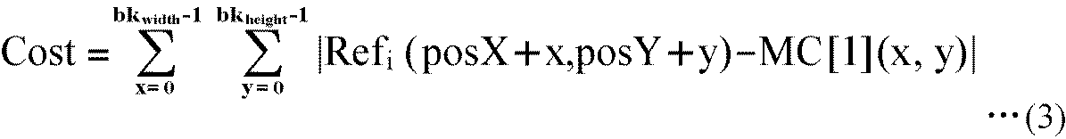

ここで、以上の構成を有する復号装置1の処理について説明する。 [Description of the flow of decryption processing]
Here, the processing of the
[符号化装置の構成]
次に、符号化側の装置の構成と動作について説明する。 <2. Second embodiment>
[Configuration of Encoding Device]
Next, the configuration and operation of the coding apparatus will be described.
次に、以上のような構成を有する符号化装置101の処理について説明する。 [Description of flow of encoding process]
Next, the processing of the coding apparatus 101 having the above configuration will be described.
[フィルタリング回路の変形例]
以上においては、フィルタリング回路45,185は図10に示されるような構成を有するものとしたが、この構成は適宜変更可能である。 <3. Third embodiment>
[Modification of filtering circuit]
Although the
Claims (16)
- 符号化された画像を復号する復号手段と、
前記復号手段により復号された画像と予測画像を加算し、復号済みの画像を生成する生成手段と、
前記生成手段により生成された復号済みの画像からなるフレームを参照フレームとして、符号化された前記画像の動きベクトルを用いて動き補償を行い、前記予測画像に対応する動き補償画像を前記参照フレームから抽出する第1の抽出手段と、
前記動き補償画像が抽出された前記参照フレームと異なる参照フレームにおいて、前記第1の抽出手段により抽出された前記動き補償画像に一致または近似する部分を、前記予測画像に対応する動き補償画像として前記参照フレームから抽出する第2の抽出手段と、 前記第1の抽出手段により抽出された前記動き補償画像および前記第2の抽出手段により抽出された前記動き補償画像に対して、前記動き補償画像に含まれる時間方向の相関を利用して高周波成分を補うフィルタリング処理を行うことにより、前記予測画像を生成する予測画像生成手段と
を備える画像処理装置。 Decoding means for decoding the encoded image;
Generation means for adding the image decoded by the decoding means and the predicted image to generate a decoded image;
The motion compensation is performed using the encoded motion vector of the image with the frame including the decoded image generated by the generation unit as a reference frame, and the motion compensated image corresponding to the predicted image is extracted from the reference frame First extracting means for extracting;
In a reference frame different from the reference frame from which the motion compensated image is extracted, a portion that matches or approximates to the motion compensated image extracted by the first extracting unit is the motion compensated image corresponding to the predicted image. A second extraction unit for extracting from a reference frame; a motion compensated image for the motion compensated image extracted by the first extraction unit and the motion compensated image extracted by the second extraction unit; An image processing apparatus comprising: predicted image generation means for generating the predicted image by performing filtering processing for compensating high frequency components by using correlation in the time direction included. - 前記第2の抽出手段は、前記画像を符号化する符号化装置と共有する所定のコスト関数を用いて、前記第1の抽出手段により抽出された前記動き補償画像に一致または近似する部分を、前記予測画像に対応する動き補償画像として前記参照フレームから抽出する
請求項1に記載の画像処理装置。 The second extraction unit matches a part that matches or approximates the motion compensated image extracted by the first extraction unit using a predetermined cost function shared with the encoding device that encodes the image, The image processing apparatus according to claim 1, wherein the image processing apparatus extracts the motion compensated image corresponding to the predicted image from the reference frame. - 前記コスト関数は、前記第1の抽出手段により抽出された前記動き補償画像と前記参照フレームの処理対象ブロックとの各画素値の差分値の絶対値の総和を求める関数である
請求項2に記載の画像処理装置。 The cost function is a function for obtaining a sum of absolute values of difference values of pixel values of the motion-compensated image extracted by the first extraction unit and the processing target block of the reference frame. Image processing device. - 前記コスト関数は、前記第1の抽出手段により抽出された前記動き補償画像と前記参照フレームの処理対象ブロックとの各画素値の最小2乗誤差を求める関数である
請求項2に記載の画像処理装置。 The image processing according to claim 2, wherein the cost function is a function for obtaining a least square error of each pixel value of the motion compensated image extracted by the first extraction unit and the processing target block of the reference frame. apparatus. - 前記予測画像生成手段は、
前記第1の抽出手段により抽出された前記動き補償画像と前記第2の抽出手段により抽出された前記動き補償画像との差分画像にローパスフィルタをかける第1のフィルタ手段と、
前記第1のフィルタ手段によりローパスフィルタがかけられることによって得られた画像にハイパスフィルタをかける第2のフィルタ手段と、
前記第1のフィルタ手段によりローパスフィルタがかけられることによって得られた画像と、前記第2のフィルタ手段によりハイパスフィルタがかけられることによって得られた画像とを、前記第1の抽出手段により抽出された前記動き補償画像および前記第2の抽出手段により抽出された前記動き補償画像のうちのいずれかに加算し、前記予測画像を生成する加算手段と
を備える請求項1に記載の画像処理装置。 The predicted image generation unit
First filter means for applying a low pass filter to a difference image between the motion compensated image extracted by the first extracting means and the motion compensated image extracted by the second extracting means;
Second filter means for high pass filtering an image obtained by applying low pass filter by the first filter means;
An image obtained by applying the low pass filter by the first filter unit and an image obtained by applying the high pass filter by the second filter unit are extracted by the first extracting unit. The image processing apparatus according to claim 1, further comprising: addition means for adding to any one of the motion compensated image and the motion compensated image extracted by the second extracting means to generate the predicted image. - 前記加算手段は、前記予測画像の時刻を基準として1時刻前のフレームから抽出された前記動き補償画像に対して、前記第1のフィルタ手段によりローパスフィルタがかけられることによって得られた画像と、前記第2のフィルタ手段によりハイパスフィルタがかけられることによって得られた画像とを加算する
請求項5に記載の画像処理装置。 The addition means is an image obtained by applying the low pass filter by the first filter means to the motion compensated image extracted from the frame one time before on the basis of the time of the predicted image; The image processing apparatus according to claim 5, wherein the image processing apparatus adds an image obtained by applying a high pass filter by the second filter unit. - 複数の前記動き補償画像を用いて片方向予測を行い、前記予測画像を生成する片方向予測手段と、
複数の前記動き補償画像を用いて双方向予測を行い、前記予測画像を生成する双方向予測手段と、
符号化された前記画像のヘッダに含まれる識別フラグにより、前記予測画像を、前記片方向予測手段による片方向予測によって生成するのか、前記双方向予測手段による双方向予測によって生成するのか、または、前記予測画像生成手段による前記フィルタリング処理によって生成するのかを判定する判定手段と
をさらに備える請求項1に記載の画像処理装置。 Uni-directional prediction means for performing uni-directional prediction using a plurality of motion compensated images and generating the predicted image;
Bidirectional prediction means for performing bidirectional prediction using a plurality of the motion compensated images to generate the predicted image;
Depending on the identification flag included in the header of the encoded image, the predicted image may be generated by unidirectional prediction by the unidirectional prediction unit, or may be generated by bidirectional prediction by the bidirectional prediction unit, or The image processing apparatus according to claim 1, further comprising: a determination unit that determines whether to generate the filtering process by the predicted image generation unit. - 符号化された画像を復号し、
復号された画像と予測画像を加算し、復号済みの画像を生成し、
生成された復号済みの画像からなるフレームを参照フレームとして、符号化された前記画像の動きベクトルを用いて動き補償を行い、前記予測画像に対応する動き補償画像を前記参照フレームから抽出し、
前記動き補償画像が抽出された前記参照フレームと異なる参照フレームにおいて、抽出された前記動き補償画像に一致または近似する部分を、前記予測画像に対応する動き補償画像として前記参照フレームから抽出し、
抽出された複数の前記動き補償画像に対して、前記動き補償画像に含まれる時間方向の相関を利用して高周波成分を補うフィルタリング処理を行うことにより、前記予測画像を生成する
画像処理方法。 Decode the encoded image,
Add the decoded image and the predicted image to generate a decoded image,
Motion compensation is performed using a motion vector of the encoded image using a frame including the generated decoded image as a reference frame, and a motion compensated image corresponding to the predicted image is extracted from the reference frame;
In a reference frame different from the reference frame from which the motion compensated image is extracted, a portion that matches or approximates the extracted motion compensated image is extracted from the reference frame as a motion compensated image corresponding to the predicted image,
An image processing method for generating the predicted image by performing a filtering process on a plurality of extracted motion compensated images to compensate a high frequency component using a correlation in a time direction included in the motion compensated image. - 符号化対象の画像である原画像を符号化し、符号化された画像を生成する符号化手段と、
前記原画像と予測画像との差を示す残差信号に基づいて局所的に復号して得られた画像と前記原画像とに基づいて動きベクトルを検出する検出手段と、
局所的に復号して得られた前記画像からなるフレームを参照フレームとして、前記検出手段により検出された動きベクトルを用いて動き補償を行い、前記予測画像に対応する動き補償画像を前記参照フレームから抽出する第1の抽出手段と、
前記動き補償画像が抽出された前記参照フレームと異なる参照フレームにおいて、前記第1の抽出手段により抽出された前記動き補償画像に一致または近似する部分を、前記予測画像に対応する動き補償画像として前記参照フレームから抽出する第2の抽出手段と、 前記第1の抽出手段により抽出された前記動き補償画像および前記第2の抽出手段により抽出された前記動き補償画像に対して、前記動き補償画像に含まれる時間方向の相関を利用して高周波成分を補うフィルタリング処理を行うことにより、前記予測画像を生成する生成手段と
を備える画像処理装置。 Encoding means for encoding an original image that is an image to be encoded and generating an encoded image;
A detection means for detecting a motion vector based on an image obtained by locally decoding based on a residual signal indicating a difference between the original image and a predicted image, and the original image;
A motion compensation is performed using a frame consisting of the image obtained by locally decoding as a reference frame, using a motion vector detected by the detection means, and a motion compensated image corresponding to the predicted image from the reference frame First extracting means for extracting;
In a reference frame different from the reference frame from which the motion compensated image is extracted, a portion that matches or approximates to the motion compensated image extracted by the first extracting unit is the motion compensated image corresponding to the predicted image. A second extraction unit for extracting from a reference frame; a motion compensated image for the motion compensated image extracted by the first extraction unit and the motion compensated image extracted by the second extraction unit; An image processing apparatus comprising: generation means for generating the predicted image by performing filtering processing for compensating high frequency components by using correlation in the time direction included. - 前記第2の抽出手段は、符号化された前記画像を復号する復号装置と共有する所定のコスト関数を用いて、前記第1の抽出手段により抽出された前記動き補償画像に一致または近似する部分を、前記予測画像に対応する動き補償画像として前記参照フレームから抽出する
請求項9に記載の画像処理装置。 The second extraction unit matches or approximates the motion compensated image extracted by the first extraction unit using a predetermined cost function shared with a decoding device that decodes the encoded image The image processing apparatus according to claim 9, wherein the image processing apparatus is extracted from the reference frame as a motion compensated image corresponding to the predicted image. - 前記コスト関数は、前記第1の抽出手段により抽出された前記動き補償画像と前記参照フレームの処理対象ブロックとの各画素値の差分値の絶対値の総和を求める関数である
請求項10に記載の画像処理装置。 The cost function is a function for obtaining a sum of absolute values of difference values of pixel values of the motion-compensated image extracted by the first extraction unit and the processing target block of the reference frame. Image processing device. - 前記コスト関数は、前記第1の抽出手段により抽出された前記動き補償画像と前記参照フレームの処理対象ブロックとの各画素値の最小2乗誤差を求める関数である
請求項10に記載の画像処理装置。 The image processing according to claim 10, wherein the cost function is a function for obtaining a least square error of each pixel value of the motion compensated image extracted by the first extraction unit and the processing target block of the reference frame. apparatus. - 前記生成手段は、
前記第1の抽出手段により抽出された前記動き補償画像および前記第2の抽出手段により抽出された前記動き補償画像の差分画像にローパスフィルタをかける第1のフィルタ手段と、
前記第1のフィルタ手段によりローパスフィルタがかけられることによって得られた画像にハイパスフィルタをかける第2のフィルタ手段と、
前記第1のフィルタ手段によりローパスフィルタがかけられることによって得られた画像と、前記第2のフィルタ手段によりハイパスフィルタがかけられることによって得られた画像とを、前記第1の抽出手段により抽出された前記動き補償画像および前記第2の抽出手段により抽出された前記動き補償画像のうちのいずれかに加算し、前記予測画像を生成する加算手段と
を備える請求項9に記載の画像処理装置。 The generation means is
First filter means for low pass filtering the difference image of the motion compensated image extracted by the first extraction means and the motion compensated image extracted by the second extraction means;
Second filter means for high pass filtering an image obtained by applying low pass filter by the first filter means;
An image obtained by applying the low pass filter by the first filter unit and an image obtained by applying the high pass filter by the second filter unit are extracted by the first extracting unit. 10. The image processing apparatus according to claim 9, further comprising: addition means for adding to any one of the motion compensated image and the motion compensated image extracted by the second extracting unit to generate the predicted image. - 前記加算手段は、前記予測画像の時刻を基準として1時刻前のフレームから抽出された前記動き補償画像に対して、前記第1のフィルタ手段によりローパスフィルタがかけられることによって得られた画像と、前記第2のフィルタ手段によりハイパスフィルタがかけられることによって得られた画像とを加算する
請求項13に記載の画像処理装置。 The addition means is an image obtained by applying the low pass filter by the first filter means to the motion compensated image extracted from the frame one time before on the basis of the time of the predicted image; The image processing apparatus according to claim 13, wherein the image processing apparatus adds an image obtained by applying a high-pass filter by the second filter unit. - 前記符号化手段は、復号装置において復号した画像に加算する予測画像を、片方向予測によって生成するのか、双方向予測によって生成するのか、または、前記フィルタリング処理によって生成するのかを識別する識別フラグを、符号化された前記画像のヘッダに含める
請求項9に記載の画像処理装置。 The encoding means identifies an identification flag identifying whether to generate a predicted image to be added to the image decoded by the decoding device by one-way prediction, bidirectional prediction, or the filtering process. The image processing apparatus according to claim 9, wherein the image processing apparatus is included in the header of the encoded image. - 符号化対象の画像である原画像を符号化し、符号化された画像を生成し、
前記原画像と予測画像との差を示す残差信号に基づいて局所的に復号して得られた画像と前記原画像とに基づいて動きベクトルを検出し、
局所的に復号して得られた前記画像からなるフレームを参照フレームとして、検出された動きベクトルを用いて動き補償を行い、前記予測画像に対応する動き補償画像を前記参照フレームから抽出し、
前記動き補償画像が抽出された前記参照フレームと異なる参照フレームにおいて、抽出された前記動き補償画像に一致または近似する部分を、前記予測画像に対応する動き補償画像として前記参照フレームから抽出し、
抽出された複数の前記動き補償画像に対して、前記動き補償画像に含まれる時間方向の相関を利用して高周波成分を補うフィルタリング処理を行うことにより、前記予測画像を生成する
画像処理方法。 Encoding an original image which is an image to be encoded to generate an encoded image;
A motion vector is detected based on an image obtained by locally decoding based on a residual signal indicating a difference between the original image and a predicted image, and the original image;
A motion compensation is performed using a detected motion vector as a reference frame, and a motion compensated image corresponding to the predicted image is extracted from the reference frame, using a frame formed of the image obtained by local decoding as a reference frame,
In a reference frame different from the reference frame from which the motion compensated image is extracted, a portion that matches or approximates the extracted motion compensated image is extracted from the reference frame as a motion compensated image corresponding to the predicted image,
An image processing method for generating the predicted image by performing a filtering process on a plurality of extracted motion compensated images to compensate a high frequency component using a correlation in a time direction included in the motion compensated image.
Priority Applications (15)
| Application Number | Priority Date | Filing Date | Title |
|---|---|---|---|
| EP13170853.9A EP2637408B1 (en) | 2009-02-19 | 2010-02-12 | Image processing device and method |
| EP18187944.6A EP3422715A1 (en) | 2009-02-19 | 2010-02-12 | Image processing device and method |
| US13/201,351 US8457422B2 (en) | 2009-02-19 | 2010-02-12 | Image processing device and method for generating a prediction image |
| CN201080016294.7A CN102396226B (en) | 2009-02-19 | 2010-02-12 | Image processing device and method |
| BRPI1008504A BRPI1008504A2 (en) | 2009-02-19 | 2010-02-12 | image processing device and method |
| EP10743684A EP2400761A4 (en) | 2009-02-19 | 2010-02-12 | Image processing device and method |
| RU2011134046/08A RU2524872C2 (en) | 2009-02-19 | 2010-02-12 | Image processing method and device |
| KR1020167014399A KR101736015B1 (en) | 2009-02-19 | 2010-02-12 | Image processing device and method |
| JP2011500573A JP5532346B2 (en) | 2009-02-19 | 2010-02-12 | Image processing apparatus and method |
| US13/887,148 US8995779B2 (en) | 2009-02-19 | 2013-05-03 | Image processing device and method for generating a prediction image |
| US14/635,649 US9462294B2 (en) | 2009-02-19 | 2015-03-02 | Image processing device and method to enable generation of a prediction image |
| US15/256,022 US9872020B2 (en) | 2009-02-19 | 2016-09-02 | Image processing device and method for generating prediction image |
| US15/842,372 US10334244B2 (en) | 2009-02-19 | 2017-12-14 | Image processing device and method for generation of prediction image |
| US16/407,416 US10931944B2 (en) | 2009-02-19 | 2019-05-09 | Decoding device and method to generate a prediction image |
| US17/157,535 US20210144367A1 (en) | 2009-02-19 | 2021-01-25 | Image processing device and method |
Applications Claiming Priority (2)
| Application Number | Priority Date | Filing Date | Title |
|---|---|---|---|
| JP2009-036498 | 2009-02-19 | ||
| JP2009036498 | 2009-02-19 |
Related Child Applications (3)
| Application Number | Title | Priority Date | Filing Date |
|---|---|---|---|
| US13/201,351 A-371-Of-International US8457422B2 (en) | 2009-02-19 | 2010-02-12 | Image processing device and method for generating a prediction image |
| US13877148 Continuation | 2013-05-03 | ||
| US13/887,148 Continuation US8995779B2 (en) | 2009-02-19 | 2013-05-03 | Image processing device and method for generating a prediction image |
Publications (1)
| Publication Number | Publication Date |
|---|---|
| WO2010095557A1 true WO2010095557A1 (en) | 2010-08-26 |
Family
ID=42633840
Family Applications (1)
| Application Number | Title | Priority Date | Filing Date |
|---|---|---|---|
| PCT/JP2010/052017 WO2010095557A1 (en) | 2009-02-19 | 2010-02-12 | Image processing device and method |
Country Status (9)
| Country | Link |
|---|---|
| US (7) | US8457422B2 (en) |
| EP (3) | EP3422715A1 (en) |
| JP (2) | JP5532346B2 (en) |
| KR (2) | KR101736015B1 (en) |
| CN (3) | CN104023239B (en) |
| BR (1) | BRPI1008504A2 (en) |
| RU (3) | RU2524872C2 (en) |
| TW (1) | TWI463878B (en) |
| WO (1) | WO2010095557A1 (en) |
Cited By (2)
| Publication number | Priority date | Publication date | Assignee | Title |
|---|---|---|---|---|
| JP2020178379A (en) * | 2010-09-29 | 2020-10-29 | サン パテント トラスト | Decoding method, encoding method, decoder, encoder and program |
| US11310500B2 (en) | 2010-09-30 | 2022-04-19 | Sun Patent Trust | Image decoding method, image coding method, image decoding apparatus, image coding apparatus, program, and integrated circuit |
Families Citing this family (19)
| Publication number | Priority date | Publication date | Assignee | Title |
|---|---|---|---|---|
| TWI463878B (en) * | 2009-02-19 | 2014-12-01 | Sony Corp | Image processing apparatus and method |
| TWI468020B (en) | 2009-02-19 | 2015-01-01 | Sony Corp | Image processing apparatus and method |
| TWI440363B (en) | 2009-02-19 | 2014-06-01 | Sony Corp | Image processing apparatus and method |
| US20120106622A1 (en) * | 2010-11-03 | 2012-05-03 | Mediatek Inc. | Method and Apparatus of Slice Grouping for High Efficiency Video Coding |
| WO2012081246A1 (en) | 2010-12-17 | 2012-06-21 | パナソニック株式会社 | Image encoding method and image decoding method |
| US8849054B2 (en) * | 2010-12-23 | 2014-09-30 | Samsung Electronics Co., Ltd | Digital image stabilization |
| JP2012253722A (en) * | 2011-06-07 | 2012-12-20 | Sony Corp | Image coding apparatus, image decoding apparatus, image coding method, image decoding method, and program |
| WO2013109124A1 (en) | 2012-01-19 | 2013-07-25 | 삼성전자 주식회사 | Method and device for encoding video to limit bidirectional prediction and block merging, and method and device for decoding video |
| JP6232828B2 (en) * | 2013-08-13 | 2017-11-22 | 日本電気株式会社 | Still image providing device |
| US9737375B2 (en) * | 2015-06-11 | 2017-08-22 | Avid, Inc. | Dental handpiece and prophy angle |
| US10321831B2 (en) | 2015-11-25 | 2019-06-18 | Texas Instruments Incorporated | Heart rate estimation apparatus with state sequence optimization |
| US10758185B2 (en) * | 2015-11-25 | 2020-09-01 | Texas Instruments Incorporated | Heart rate estimation apparatus using digital automatic gain control |
| US10729381B2 (en) | 2016-06-24 | 2020-08-04 | Texas Instruments Incorporated | Photoplethysmogram with motion artifact compensation |
| EP3561447B1 (en) * | 2017-01-25 | 2023-11-22 | National Institute of Advanced Industrial Science and Technology | Image processing method |
| CN110462363B (en) * | 2017-03-28 | 2021-07-06 | 株式会社神户制钢所 | Tire testing method and tire testing device |
| US10248891B2 (en) | 2017-06-20 | 2019-04-02 | At&T Intellectual Property I, L.P. | Image prediction |
| JP6904200B2 (en) * | 2017-09-27 | 2021-07-14 | 株式会社Jvcケンウッド | Motion vector detector |
| CN112492249B (en) * | 2019-09-11 | 2024-04-09 | 瑞昱半导体股份有限公司 | Image processing method and circuit |
| CN115173886B (en) * | 2022-09-06 | 2022-11-29 | 深圳市国芯物联科技有限公司 | Echo cancellation system applied to long-distance UHF RFID reader-writer |
Citations (2)
| Publication number | Priority date | Publication date | Assignee | Title |
|---|---|---|---|---|
| JP2006108811A (en) * | 2004-09-30 | 2006-04-20 | Sanyo Electric Co Ltd | Image encoding method |
| JP2007300380A (en) * | 2006-04-28 | 2007-11-15 | Ntt Docomo Inc | Image predictive encoding device, image predictive encoding method, image predictive encoding program, image predictive decoding device, image predictive decoding method, and image predictive decoding program |
Family Cites Families (85)
| Publication number | Priority date | Publication date | Assignee | Title |
|---|---|---|---|---|
| US4794455A (en) * | 1987-01-07 | 1988-12-27 | Pictel Corporation | Method and apparatus employing adaptive filtering for efficiently communicating image sequences |
| JPH0832047B2 (en) * | 1989-04-28 | 1996-03-27 | 日本ビクター株式会社 | Predictive coding device |
| JPH03127580A (en) * | 1989-10-13 | 1991-05-30 | Matsushita Electric Ind Co Ltd | Movement compensation inter-frame coder |
| US5150432A (en) * | 1990-03-26 | 1992-09-22 | Kabushiki Kaisha Toshiba | Apparatus for encoding/decoding video signals to improve quality of a specific region |
| US5467136A (en) * | 1991-05-31 | 1995-11-14 | Kabushiki Kaisha Toshiba | Video decoder for determining a motion vector from a scaled vector and a difference vector |
| JPH06113265A (en) * | 1992-09-25 | 1994-04-22 | Fujitsu Ltd | Motion compensation predicting unit |
| JP3165296B2 (en) * | 1992-12-25 | 2001-05-14 | 三菱電機株式会社 | Inter-frame coding processing method, inter-frame coding processing method, and coding control method |
| JP2947103B2 (en) | 1994-11-25 | 1999-09-13 | 日本ビクター株式会社 | Moving picture coding apparatus and moving picture coding method |
| ES2206358T3 (en) * | 1996-05-17 | 2004-05-16 | Matsushita Electric Industrial Co., Ltd. | VIDEO CODING PROCEDURE FOR CODING SIGNALS AND TEXTURE SIGNS USING VARIOUS MODALITIES. |
| JPH1079947A (en) * | 1996-09-03 | 1998-03-24 | Mitsubishi Electric Corp | Motion vector detecting device |
| JP3263807B2 (en) * | 1996-09-09 | 2002-03-11 | ソニー株式会社 | Image encoding apparatus and image encoding method |
| KR100303685B1 (en) * | 1996-09-30 | 2001-09-24 | 송문섭 | Image prediction encoding device and method thereof |
| US6088047A (en) * | 1997-12-30 | 2000-07-11 | Sony Corporation | Motion compensated digital video decoding with buffered picture storage memory map |
| EP0926899A3 (en) * | 1997-12-25 | 1999-12-15 | SANYO ELECTRIC Co., Ltd. | An apparatus and process for decoding motion pictures |
| CN1166207C (en) | 1999-05-27 | 2004-09-08 | 皇家菲利浦电子有限公司 | Encoding a video signal |
| JP3478209B2 (en) * | 1999-11-01 | 2003-12-15 | 日本電気株式会社 | Audio signal decoding method and apparatus, audio signal encoding and decoding method and apparatus, and recording medium |
| US7630566B2 (en) * | 2001-09-25 | 2009-12-08 | Broadcom Corporation | Method and apparatus for improved estimation and compensation in digital video compression and decompression |
| EP2320660B8 (en) * | 2001-11-29 | 2015-09-09 | Godo Kaisha IP Bridge 1 | Coding distortion removal method |
| JP3997171B2 (en) * | 2003-03-27 | 2007-10-24 | 株式会社エヌ・ティ・ティ・ドコモ | Moving picture encoding apparatus, moving picture encoding method, moving picture encoding program, moving picture decoding apparatus, moving picture decoding method, and moving picture decoding program |
| EP3787295B1 (en) | 2003-07-24 | 2022-09-21 | Nippon Telegraph And Telephone Corporation | Image decoding method with hierarchical reference picture selection |
| CN1843038B (en) * | 2003-08-26 | 2010-09-22 | 汤姆森特许公司 | Method and apparatus for decoding hybrid intra-inter coded blocks |
| US7295612B2 (en) * | 2003-09-09 | 2007-11-13 | Apple Inc. | Determining the number of unidirectional and bidirectional motion compensated frames to be encoded for a video sequence and detecting scene cuts in the video sequence |
| BRPI0414397A (en) * | 2003-09-17 | 2006-11-21 | Thomson Licensing | adaptive reference imaging |
| JP4289126B2 (en) * | 2003-11-04 | 2009-07-01 | ソニー株式会社 | Data processing apparatus and method and encoding apparatus |
| MXPA06006107A (en) * | 2003-12-01 | 2006-08-11 | Samsung Electronics Co Ltd | Method and apparatus for scalable video encoding and decoding. |
| TWI255146B (en) * | 2003-12-04 | 2006-05-11 | Nec Corp | Moving picture encoding method and device, and moving picture decoding method and device, and storage medium |
| JP2005217940A (en) * | 2004-01-30 | 2005-08-11 | Ntt Docomo Inc | Apparatus and method for coding moving image, and moving image coding program |
| KR100703283B1 (en) * | 2004-03-15 | 2007-04-03 | 삼성전자주식회사 | Image encoding apparatus and method for estimating motion using rotation matching |
| EP1599046A1 (en) * | 2004-05-19 | 2005-11-23 | THOMSON Licensing | Method for coding video data of a sequence of pictures |
| KR101182977B1 (en) * | 2004-06-29 | 2012-09-18 | 소니 주식회사 | Motion prediction compensation method and motion prediction compensation device |
| US8442108B2 (en) * | 2004-07-12 | 2013-05-14 | Microsoft Corporation | Adaptive updates in motion-compensated temporal filtering |
| CN101019436B (en) * | 2004-07-13 | 2013-05-08 | 法国电讯公司 | Method and device for encoding a video a video image sequence |
| KR100644620B1 (en) * | 2004-07-29 | 2006-11-10 | 삼성전자주식회사 | Method and apparatus for decoding moving picture which post filtering is applied |
| KR20060027779A (en) * | 2004-09-23 | 2006-03-28 | 엘지전자 주식회사 | Method and apparatus for encoding/decoding video signal using temporal and spatial correlations between macro blocks |
| EP1646243B1 (en) * | 2004-09-30 | 2009-06-24 | Kabushiki Kaisha Toshiba | Information processing apparatus and program for use in the same |
| JP4501676B2 (en) * | 2004-12-22 | 2010-07-14 | 日本電気株式会社 | Video compression encoding method, video compression encoding apparatus, and program |
| US20060153295A1 (en) | 2005-01-12 | 2006-07-13 | Nokia Corporation | Method and system for inter-layer prediction mode coding in scalable video coding |
| US8218634B2 (en) * | 2005-01-13 | 2012-07-10 | Ntt Docomo, Inc. | Nonlinear, in-the-loop, denoising filter for quantization noise removal for hybrid video compression |
| KR100703770B1 (en) * | 2005-03-25 | 2007-04-06 | 삼성전자주식회사 | Video coding and decoding using weighted prediction, and apparatus for the same |
| WO2006108654A2 (en) * | 2005-04-13 | 2006-10-19 | Universität Hannover | Method and apparatus for enhanced video coding |
| US7564652B2 (en) * | 2005-07-06 | 2009-07-21 | Sae Magnetics (H.K.) Ltd. | Head gimbal assembly including a one-piece structural suspension and an accessory plate, and method of manufacturing the same |
| EP1902586B1 (en) | 2005-07-11 | 2014-09-24 | Thomson Licensing | Method and apparatus for macroblock adaptive inter-layer intra texture prediction |
| MX2008000906A (en) | 2005-07-21 | 2008-03-18 | Thomson Licensing | Method and apparatus for weighted prediction for scalable video coding. |
| US20090123066A1 (en) * | 2005-07-22 | 2009-05-14 | Mitsubishi Electric Corporation | Image encoding device, image decoding device, image encoding method, image decoding method, image encoding program, image decoding program, computer readable recording medium having image encoding program recorded therein, |
| US8488889B2 (en) * | 2005-07-22 | 2013-07-16 | Mitsubishi Electric Corporation | Image encoder and image decoder, image encoding method and image decoding method, image encoding program and image decoding program, and computer readable recording medium recorded with image encoding program and computer readable recording medium recorded with image decoding program |
| US7743912B2 (en) * | 2005-08-05 | 2010-06-29 | Finley Dana J | Liquid seal bulk feeder for destructive distillation of lightweight materials |
| JP5017825B2 (en) | 2005-09-15 | 2012-09-05 | ソニー株式会社 | Decoding device and decoding method |
| US8005308B2 (en) * | 2005-09-16 | 2011-08-23 | Sony Corporation | Adaptive motion estimation for temporal prediction filter over irregular motion vector samples |
| KR100763194B1 (en) | 2005-10-14 | 2007-10-04 | 삼성전자주식회사 | Intra base prediction method satisfying single loop decoding condition, video coding method and apparatus using the prediction method |
| US8681867B2 (en) * | 2005-10-18 | 2014-03-25 | Qualcomm Incorporated | Selective deblock filtering techniques for video coding based on motion compensation resulting in a coded block pattern value |
| JP4334533B2 (en) * | 2005-11-24 | 2009-09-30 | 株式会社東芝 | Video encoding / decoding method and apparatus |
| KR100712550B1 (en) | 2006-02-03 | 2007-05-02 | 삼성전자주식회사 | High-density recording method of hard disk drive |
| JP2007221208A (en) * | 2006-02-14 | 2007-08-30 | Toshiba Corp | Method and device for encoding moving picture |
| EP1835749A1 (en) * | 2006-03-16 | 2007-09-19 | THOMSON Licensing | Method for coding video data of a sequence of pictures |
| JP4417919B2 (en) * | 2006-03-31 | 2010-02-17 | 株式会社東芝 | Image encoding apparatus and image decoding apparatus |
| AU2007244443A1 (en) | 2006-04-28 | 2007-11-08 | Ntt Docomo, Inc. | Image predictive coding device, image predictive coding method, image predictive coding program, image predictive decoding device, image predictive decoding method and image predictive decoding program |
| CN101998120B (en) * | 2006-05-24 | 2014-07-30 | 松下电器产业株式会社 | Image coding device, image coding method, and image coding integrated circuit |
| US7864219B2 (en) * | 2006-06-15 | 2011-01-04 | Victor Company Of Japan, Ltd. | Video-signal layered coding and decoding methods, apparatuses, and programs with spatial-resolution enhancement |
| JP4844455B2 (en) * | 2006-06-15 | 2011-12-28 | 日本ビクター株式会社 | Video signal hierarchical decoding device, video signal hierarchical decoding method, and video signal hierarchical decoding program |
| KR101566557B1 (en) * | 2006-10-18 | 2015-11-05 | 톰슨 라이센싱 | Method and apparatus for video coding using prediction data refinement |
| FR2907630A1 (en) * | 2006-10-19 | 2008-04-25 | Thomson Licensing Sas | DEVICE AND METHOD FOR SCALABLE FORMAT CODING OF IMAGE SEQUENCE AND CORRESPONDING DECODING DEVICE AND METHOD |
| KR101356734B1 (en) * | 2007-01-03 | 2014-02-05 | 삼성전자주식회사 | Method and apparatus for video encoding, and method and apparatus for video decoding using motion vector tracking |
| KR101365575B1 (en) * | 2007-02-05 | 2014-02-25 | 삼성전자주식회사 | Method and apparatus for encoding and decoding based on inter prediction |
| JP2010135864A (en) * | 2007-03-29 | 2010-06-17 | Toshiba Corp | Image encoding method, device, image decoding method, and device |
| JP4877090B2 (en) | 2007-06-18 | 2012-02-15 | ソニー株式会社 | Image processing apparatus, image processing method, and program |
| JP4356777B2 (en) | 2007-06-18 | 2009-11-04 | ソニー株式会社 | Image processing apparatus, image processing method, program, and recording medium |
| JP4826546B2 (en) | 2007-06-18 | 2011-11-30 | ソニー株式会社 | Image processing apparatus, image processing method, and program |
| US20090003449A1 (en) * | 2007-06-28 | 2009-01-01 | Mitsubishi Electric Corporation | Image encoding device, image decoding device, image encoding method and image decoding method |
| WO2009059152A1 (en) | 2007-10-31 | 2009-05-07 | Boston Scientific Neuromodulation Corp. | Connector assemblies for implantable stimulators |
| JPWO2010010943A1 (en) | 2008-07-25 | 2012-01-05 | ソニー株式会社 | Image processing apparatus and method |
| WO2010010942A1 (en) | 2008-07-25 | 2010-01-28 | ソニー株式会社 | Image processing device and method |
| JP5502336B2 (en) * | 2009-02-06 | 2014-05-28 | パナソニック株式会社 | Video signal encoding apparatus and video signal encoding method |
| CN102165778A (en) * | 2009-02-10 | 2011-08-24 | 松下电器产业株式会社 | Image processing apparatus, image processing method, program and integrated circuit |
| TWI463878B (en) * | 2009-02-19 | 2014-12-01 | Sony Corp | Image processing apparatus and method |
| TWI440363B (en) * | 2009-02-19 | 2014-06-01 | Sony Corp | Image processing apparatus and method |
| TWI468020B (en) * | 2009-02-19 | 2015-01-01 | Sony Corp | Image processing apparatus and method |
| JP2011030184A (en) * | 2009-07-01 | 2011-02-10 | Sony Corp | Image processing apparatus, and image processing method |
| JP5253312B2 (en) * | 2009-07-16 | 2013-07-31 | ルネサスエレクトロニクス株式会社 | Moving image processing apparatus and operation method thereof |
| JP5321439B2 (en) * | 2009-12-15 | 2013-10-23 | 株式会社Jvcケンウッド | Image encoding device, image decoding device, image encoding method, and image decoding method |
| EP2555523A4 (en) * | 2010-03-31 | 2016-05-11 | Mitsubishi Electric Corp | Image encoding device, image decoding device, image encoding method, and image decoding method |
| JP2012034225A (en) * | 2010-07-30 | 2012-02-16 | Canon Inc | Motion vector detection device, motion vector detection method and computer program |
| US9706214B2 (en) * | 2010-12-24 | 2017-07-11 | Microsoft Technology Licensing, Llc | Image and video decoding implementations |
| CA2999848C (en) * | 2015-09-25 | 2020-08-18 | Huawei Technologies Co., Ltd. | Apparatus and method for video motion compensation |
| US11924409B2 (en) * | 2021-02-21 | 2024-03-05 | Alibaba (China) Co., Ltd. | Systems and methods for inter prediction compensation |
| US20220360814A1 (en) * | 2021-05-06 | 2022-11-10 | Apple Inc. | Enhanced motion vector prediction |
-
2009
- 2009-11-30 TW TW098140834A patent/TWI463878B/en not_active IP Right Cessation
-
2010
- 2010-02-12 KR KR1020167014399A patent/KR101736015B1/en active IP Right Grant
- 2010-02-12 WO PCT/JP2010/052017 patent/WO2010095557A1/en active Application Filing
- 2010-02-12 JP JP2011500573A patent/JP5532346B2/en not_active Expired - Fee Related
- 2010-02-12 CN CN201410291365.4A patent/CN104023239B/en not_active Expired - Fee Related
- 2010-02-12 EP EP18187944.6A patent/EP3422715A1/en not_active Withdrawn
- 2010-02-12 CN CN201410291427.1A patent/CN104023240B/en not_active Expired - Fee Related
- 2010-02-12 EP EP13170853.9A patent/EP2637408B1/en not_active Not-in-force
- 2010-02-12 RU RU2011134046/08A patent/RU2524872C2/en not_active IP Right Cessation
- 2010-02-12 EP EP10743684A patent/EP2400761A4/en not_active Withdrawn
- 2010-02-12 CN CN201080016294.7A patent/CN102396226B/en not_active Expired - Fee Related
- 2010-02-12 US US13/201,351 patent/US8457422B2/en active Active
- 2010-02-12 BR BRPI1008504A patent/BRPI1008504A2/en active Search and Examination
- 2010-02-12 KR KR1020117018754A patent/KR101629993B1/en active IP Right Grant
-
2013
- 2013-05-03 US US13/887,148 patent/US8995779B2/en active Active
-
2014
- 2014-04-28 JP JP2014093195A patent/JP5928849B2/en not_active Expired - Fee Related
- 2014-05-28 RU RU2014121708A patent/RU2658890C2/en not_active IP Right Cessation
- 2014-05-28 RU RU2014121707A patent/RU2658891C2/en not_active IP Right Cessation
-
2015
- 2015-03-02 US US14/635,649 patent/US9462294B2/en active Active
-
2016
- 2016-09-02 US US15/256,022 patent/US9872020B2/en active Active
-
2017
- 2017-12-14 US US15/842,372 patent/US10334244B2/en active Active
-
2019
- 2019-05-09 US US16/407,416 patent/US10931944B2/en active Active
-
2021
- 2021-01-25 US US17/157,535 patent/US20210144367A1/en not_active Abandoned
Patent Citations (2)
| Publication number | Priority date | Publication date | Assignee | Title |
|---|---|---|---|---|
| JP2006108811A (en) * | 2004-09-30 | 2006-04-20 | Sanyo Electric Co Ltd | Image encoding method |
| JP2007300380A (en) * | 2006-04-28 | 2007-11-15 | Ntt Docomo Inc | Image predictive encoding device, image predictive encoding method, image predictive encoding program, image predictive decoding device, image predictive decoding method, and image predictive decoding program |
Non-Patent Citations (2)
| Title |
|---|
| MICHAL IRANI, SHMUEL PELEG: "Improving Resolution by Image Registration", 16 June 1989, THE HEBREW UNIVERSITY OF JERUSALEM |
| See also references of EP2400761A4 * |
Cited By (4)
| Publication number | Priority date | Publication date | Assignee | Title |
|---|---|---|---|---|
| JP2020178379A (en) * | 2010-09-29 | 2020-10-29 | サン パテント トラスト | Decoding method, encoding method, decoder, encoder and program |
| JP7108844B2 (en) | 2010-09-29 | 2022-07-29 | サン パテント トラスト | Decoding method, encoding method, decoding device, encoding device and program |
| US11310500B2 (en) | 2010-09-30 | 2022-04-19 | Sun Patent Trust | Image decoding method, image coding method, image decoding apparatus, image coding apparatus, program, and integrated circuit |
| US11729389B2 (en) | 2010-09-30 | 2023-08-15 | Sun Patent Trust | Image decoding method, image coding method, image decoding apparatus, image coding apparatus, program, and integrated circuit |
Also Published As
Similar Documents
| Publication | Publication Date | Title |
|---|---|---|
| JP5928849B2 (en) | Image processing apparatus and method | |
| JP5812372B2 (en) | Decoding apparatus and method | |
| JP5532345B2 (en) | Image processing apparatus and method | |
| JP5641377B2 (en) | Image processing apparatus and method, program, and recording medium | |
| KR101612977B1 (en) | Image processing device and method |
Legal Events
| Date | Code | Title | Description |
|---|---|---|---|
| WWE | Wipo information: entry into national phase |
Ref document number: 201080016294.7 Country of ref document: CN |
|
| 121 | Ep: the epo has been informed by wipo that ep was designated in this application |
Ref document number: 10743684 Country of ref document: EP Kind code of ref document: A1 |
|
| ENP | Entry into the national phase |
Ref document number: 20117018754 Country of ref document: KR Kind code of ref document: A |
|
| WWE | Wipo information: entry into national phase |
Ref document number: 2011500573 Country of ref document: JP |
|
| WWE | Wipo information: entry into national phase |
Ref document number: 2011134046 Country of ref document: RU Ref document number: 13201351 Country of ref document: US Ref document number: 6151/DELNP/2011 Country of ref document: IN Ref document number: 2010743684 Country of ref document: EP |
|
| NENP | Non-entry into the national phase |
Ref country code: DE |
|
| REG | Reference to national code |
Ref country code: BR Ref legal event code: B01A Ref document number: PI1008504 Country of ref document: BR |
|
| ENP | Entry into the national phase |
Ref document number: PI1008504 Country of ref document: BR Kind code of ref document: A2 Effective date: 20110812 |