WO2010090239A1 - 無線基地局及び通信制御方法 - Google Patents
無線基地局及び通信制御方法 Download PDFInfo
- Publication number
- WO2010090239A1 WO2010090239A1 PCT/JP2010/051561 JP2010051561W WO2010090239A1 WO 2010090239 A1 WO2010090239 A1 WO 2010090239A1 JP 2010051561 W JP2010051561 W JP 2010051561W WO 2010090239 A1 WO2010090239 A1 WO 2010090239A1
- Authority
- WO
- WIPO (PCT)
- Prior art keywords
- transmission
- uplink signal
- mobile station
- base station
- radio base
- Prior art date
- Legal status (The legal status is an assumption and is not a legal conclusion. Google has not performed a legal analysis and makes no representation as to the accuracy of the status listed.)
- Ceased
Links
Images



Classifications
-
- H—ELECTRICITY
- H04—ELECTRIC COMMUNICATION TECHNIQUE
- H04W—WIRELESS COMMUNICATION NETWORKS
- H04W72/00—Local resource management
- H04W72/50—Allocation or scheduling criteria for wireless resources
- H04W72/54—Allocation or scheduling criteria for wireless resources based on quality criteria
- H04W72/541—Allocation or scheduling criteria for wireless resources based on quality criteria using the level of interference
Definitions
- the present invention relates to a radio base station and a communication control method.
- W-CDMA Wideband Code Division Multiple Access
- HSDPA high-speed downlink packet access
- HSUPA high-speed uplink packet access
- LTE Long Term Evolution
- an orthogonal frequency division multiple access (OFDMA) scheme is used for the downlink, and a single carrier frequency division multiple access (SC-FDMA) is used for the uplink. It is promising that the Single-Carrier Frequency Division Multiple Access) method will be used.
- OFDMA orthogonal frequency division multiple access
- SC-FDMA single carrier frequency division multiple access
- the OFDMA scheme is a multicarrier transmission scheme in which a frequency band is divided into a plurality of narrow frequency bands (subcarriers) and data is transmitted on each subcarrier. It can be expected that high-speed transmission can be realized by increasing the frequency utilization efficiency by arranging subcarriers densely while being orthogonal to each other on the frequency axis.
- the SC-FDMA scheme is a single carrier transmission scheme in which a frequency band is divided for each terminal and transmitted using a different frequency band among a plurality of terminals. Since the interference between terminals can be reduced easily and effectively, and the variation in transmission power can be reduced, the SC-FDMA scheme is preferable from the viewpoint of reducing the power consumption of terminals and expanding the coverage.
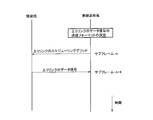
- a radio base station determines a data signal transmission format, notifies the mobile station of the transmission format, and instructs the transmission of the data signal. To be notified.
- the mobile station When receiving the control signal, the mobile station transmits a data signal to the radio base station at a predetermined timing.
- a control signal is called an uplink scheduling grant (Uplink Scheduling Grant).
- the predetermined timing is a subframe of “n + 4” where “n” is a subframe in which a control signal is transmitted.
- the uplink scheduling grant is one of downlink control information (Donlink Control Information (DCI)), and its format (DCI format) is “DCI format 0”.
- DCI Downlink Control Information
- the uplink in a mobile communication system there is an upper limit (maximum value) in the transmission power of the mobile station.
- maximum transmission power of a mobile station in an LTE mobile communication system is 23 dBm.
- the transmission power of the mobile station is limited by this maximum transmission power, it is considered that it is difficult to achieve the required SIR at the receiving end of the radio base station.
- a mobile station at a cell edge since a mobile station at a cell edge has a large path loss with a radio base station, it is necessary to transmit an uplink data signal with a large transmission power capable of compensating for the path loss.
- the power is limited by the maximum transmission power, the above-described path loss cannot be sufficiently compensated, and as a result, it becomes difficult to realize a required SIR.
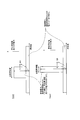
- the transmission bandwidth is reduced in Case 2 compared to Case 1, and as a result, the signal power per unit bandwidth is increased, resulting in reception of the radio base station.
- the SIR at the edge is improved.
- the SIR at the reception end of the radio base station can be reduced by reducing the transmission bandwidth. There is a way to improve.
- the present invention has been made in view of the above-described problems, and reduces interference between cells by appropriately setting the transmission frequency and transmission frequency bandwidth of an uplink data signal based on a predetermined condition. It is an object of the present invention to provide a radio base station and a communication control method that can be performed.
- a first feature of the present invention is a radio base station that communicates with a mobile station, wherein the power estimation unit is configured to estimate transmission power of an uplink signal in the mobile station, and is transmitted by the mobile station.
- a transmission format determining unit configured to determine a transmission bandwidth and a transmission frequency of the uplink signal as a transmission format of the uplink signal to be transmitted to the mobile station in the determined transmission format.
- a transmission instructing unit configured to instruct to transmit a link signal, wherein the transmission format determining unit determines a transmission bandwidth of the uplink signal based on the estimated value of the transmission power
- the gist is that the transmission frequency of the uplink signal is determined based on a predetermined condition.
- a second feature of the present invention is a communication control method in a radio base station that communicates with a mobile station, wherein the first step of estimating transmission power of an uplink signal in the mobile station is transmitted by the mobile station As a transmission format of the uplink signal, a second step of determining a transmission bandwidth and a transmission frequency of the uplink signal, and instructing the mobile station to transmit an uplink signal in the determined transmission format And determining a transmission bandwidth of the uplink signal based on the estimated value of the transmission power in the second step, and transmitting the uplink signal based on a predetermined condition.
- the gist is to determine the frequency.
- a radio base station and a communication control method can be provided.
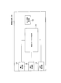
- FIG. 1 is a functional block diagram of a radio base station according to the first embodiment of the present invention.
- FIG. 2 is a diagram for explaining a method of determining a transmission format by the transmission format determination unit of the radio base station according to the first embodiment of the present invention.
- FIG. 3 is a flowchart showing an operation of the radio base station according to the first embodiment of the present invention.
- FIG. 4 is a sequence diagram showing the operation of the conventional mobile communication system.
- FIG. 5 is a diagram for explaining a method of determining a transmission format by a conventional radio base station.
- FIG. 6 is a diagram for explaining the problems of the conventional radio base station.
- Radio base station according to the first embodiment of the present invention
- the radio base station eNB which concerns on the 1st Embodiment of this invention is demonstrated.
- the radio base station eNB includes a power estimation unit 11, a cell information acquisition unit 12, a transmission format determination unit 13, a transmission instruction unit 14, and a signal reception unit 15. It has.
- the power estimation unit 11 is configured to estimate the transmission power of an uplink signal (uplink data signal) in the mobile station UE.
- the power estimation unit 11 determines the transmission power of the uplink signal in the mobile station UE based on the path loss between the radio base station eNB and the mobile station UE and the reception power of the uplink signal transmitted by the mobile station UE. It may be configured to estimate.
- the power estimation unit 11 is configured to calculate the above-described transmission power estimation value Txpow according to (Equation 1).
- Txpow 10 ⁇ log 10 N allocated + P O_PUSCH + ⁇ ⁇ PL + ⁇ TF (TF (i)) + f (i) (Formula 1)
- N allocated is the number of resource blocks (RBs) allocated for uplink signal transmission.
- PO_PUSCH is a value defined in TS36.213, which is the 3GPP standard, and is a value set via the external interface.
- f (i) is the total value of the TPC commands transmitted up to the subframe for calculating the estimated transmission power value Txpow.
- PL is the above-mentioned path loss.
- ⁇ is an attenuation factor defined in TS36.213, which is a 3GPP standard, and is a value set via an external interface. For example, it is assumed that ⁇ TF is always set to “0 dB”.
- the power estimation unit 11 calculates, for example, the transmission power of the mobile station UE from “Power Headroom” reported from the mobile station UE, and measures the reception level of the uplink signal from the mobile station UE.
- the PL (path loss) described above may be calculated based on the transmission power and the reception level.
- Power Headroom is signaling indicating the difference between the current transmission power and the maximum transmission power notified from the mobile station UE.
- the power estimation unit 11 may directly calculate PL (path loss) from the value of “Power Headroom”. Specifically, the power estimation unit 11 may calculate PL based on the following (Formula 2).
- Equation 2 is derived from the fact that “Power Headroom” reported from the mobile station UE is defined as follows.
- the cell information acquisition unit 12 is configured to acquire information related to the cell with which the mobile station UE is communicating.
- the cell information acquisition unit 12 acquires cell identification information (cell ID) that identifies a cell with which the mobile station UE is communicating as information related to a cell with which the mobile station UE is communicating. It is configured.
- the cell ID may be, for example, a physical layer cell ID, that is, a physical cell ID.
- the transmission format determination unit 13 is configured to determine the transmission format of the uplink signal transmitted by the mobile station UE.
- the transmission format of the uplink signal includes the transmission bandwidth and transmission frequency of the uplink signal.
- the transmission bandwidth of the uplink signal may be, for example, the number of resource blocks allocated to the uplink signal.
- the transmission frequency of the uplink signal may be, for example, a resource block number assigned to the uplink signal.
- the set is defined as Temporary RB Group.
- the number of RBs of the Temporary RB Group of one mobile station UE is, for example, the system bandwidth It may be one third of the number of RBs.
- the transmission bandwidth allocated to one UE is a value evenly distributed by the number of mobile stations UE in which the system band is multiplexed in the same subframe.
- the frequency position of the Temporary RB Group may be set to the subband with the highest reception SIR based on the reception SIR of each subband.
- the sub-band refers to a divided band when the system band is divided into a plurality of bands.
- the reception SIR of the subband may be determined by, for example, the reception SIR of the sounding reference signal transmitted from the mobile station UE.
- the transmission format determination unit 13 reduces the transmission bandwidth (number of resource blocks) of the Temporary RB Group based on the transmission power of the uplink signal and the transmission frequency (resource block number). ) Will be described.
- the transmission format determination unit 13 determines the transmission bandwidth of the uplink signal based on the transmission power of the uplink signal (estimated value of transmission power) estimated by the power estimation unit 11, and Based on the predetermined condition, the transmission frequency of the uplink signal is determined.
- the transmission format determination unit 13 may be configured to reduce the transmission bandwidth of the uplink signal so that the transmission power described above is equal to or less than the maximum transmission power.
- the transmission power of the uplink signal is determined by (transmission bandwidth of the uplink signal) ⁇ (transmission power per unit band of the uplink signal).
- the transmission format determination part 13 may be comprised so that the transmission frequency of an uplink signal may be determined based on the information (for example, cell ID) relevant to the cell acquired by the cell information acquisition part 12. .
- the transmission format determination unit 13 determines that the transmission power is greater than the maximum transmission power Pmax according to (Equation 3).
- the number N allocated of resource blocks that can be transmitted so as not to increase is determined, and the transmission bandwidth of the uplink signal is reduced based on the N allocated , that is, the number of resource blocks to be allocated for transmission of the uplink signal Is reduced to N allocated or less.
- the transmission format determination unit 13 is configured to delete resource blocks in the “Temporary RB Group” until the number of resource blocks allocated for uplink signal transmission is equal to or less than N allocated .
- the transmission format determination unit 13 determines that “Temporary” has a factor of only 2, 3, and 5 subcarriers until the number of resource blocks allocated for uplink signal transmission is equal to or less than N allocated.
- the resource block in the “RB Group” may be deleted.
- the transmission format determination unit 13 uses the resource block RB # in “Temporary RB Group”.
- the configuration is such that 0 to # 2 are deleted in order from the resource block with the highest frequency.
- the transmission format determination unit 13 includes the resource blocks RB # 0 to # 2 in the “Temporary RB Group” in the cell specified by the PCI whose value divided by 3 is “0”. The resource blocks RB # 1 and # 2 are deleted.
- the transmission format determination unit 13 sets the resource blocks RB # 0 to # 2 in the “Temporary RB Group” to the smallest frequency in the cell specified by the PCI whose value divided by 3 is “2”. It is configured to delete in order from the resource block.
- the transmission format determination unit 13 includes the resource blocks RB # 0 to # 2 in the “Temporary RB Group” in the cell specified by the PCI whose value divided by 3 is “2”.
- the resource blocks RB # 0 and # 1 are deleted.
- the transmission format determination unit 13 sets the resource blocks RB # 0 to # 2 in the “Temporary RB Group” to the highest frequency in the cell specified by the PCI whose value divided by 3 is “1”.
- the resource block, the resource block with the lowest frequency, the resource block with the second highest frequency, the resource block with the second lowest frequency, and so on are sequentially deleted.
- the transmission format determination unit 13 includes the resource blocks RB # 0 to # 2 in the “Temporary RB Group” in the cell specified by the PCI whose value divided by 3 is “1”. Are configured to delete resource blocks RB # 0 and # 2.
- the case where the number of resource blocks to be allocated for uplink signal transmission before deleting the resource block is “3”, but a value other than “3” (for example, “5”). Or “7” or any other value).
- the transmission format determining unit 13 is configured not to consider “MPR (Maximum Power Reduction)” defined in TS36.101 which is the 3GPP standard when determining the transmission power of the uplink signal. Also good.
- MPR Maximum Power Reduction
- the transmission format determination unit 13 may be configured to consider “MPR (Maximum Power Reduction)” defined in TS36.101, which is the 3GPP standard, when determining the transmission power of the uplink signal. Good.
- MPR Maximum Power Reduction
- the transmission instruction unit 14 is configured to instruct the mobile station UE to transmit an uplink signal in the determined transmission format.
- the transmission instruction unit 14 is configured to perform such an instruction using downlink control information, that is, the above-described uplink scheduling grant.
- the signal receiving unit 15 is configured to receive an uplink signal (uplink data signal) transmitted by the mobile station UE via a physical uplink shared channel (PUSCH: Physical Uplink Shared Channel).
- PUSCH Physical Uplink Shared Channel
- step S101 the power estimation unit 11 of the radio base station eNB according to the present embodiment estimates the transmission power of the uplink signal in the mobile station UE by (Equation 1).
- step S102 the transmission format determination unit 13 of the radio base station eNB determines the transmission bandwidth of the uplink signal based on the estimated value of the transmission power of the uplink signal, that is, according to (Equation 3).
- step S103 the transmission format determining unit 13 of the radio base station eNB determines the transmission frequency of the uplink signal based on the cell ID that identifies the cell with which the mobile station UE is communicating.
- the radio base station eNB According to the radio base station eNB according to the first embodiment of the present invention, it is possible to reduce interference between cells by appropriately setting the transmission frequency and transmission frequency bandwidth of the uplink signal based on a predetermined condition. Can do.
- the radio base station eNB when the estimated value of the uplink signal transmission power in the mobile station UE exceeds the maximum transmission power, the same “Temporary RB Group” is assigned. Interference between cells can be reduced by deleting different resource blocks from among the resource blocks in the “Temporary RB Group”.
- the uplink signal transmission frequency is determined based on the cell ID has been shown, but instead, if the uplink transmission frequency is different between adjacent cells, other than the above. With this method, the transmission frequency of the uplink signal may be determined.
- the same control may be performed using not the physical cell ID (PCI) but the ID of the scrambling code applied to each cell, the cell global ID, or the like as the cell ID.
- PCI physical cell ID
- the ID of the scrambling code applied to each cell the cell global ID, or the like as the cell ID.
- the first feature of the present embodiment is a radio base station eNB that communicates with the mobile station UE, and is configured to estimate the transmission power of an uplink signal in the mobile station UE, Transmission format determining unit 13 configured to determine the transmission bandwidth and transmission frequency of the uplink signal as the transmission format of the uplink signal transmitted by the station UE, and the determined transmission to the mobile station UE
- a transmission instructing unit configured to instruct to transmit an uplink signal in a format, and the transmission format determining unit 13 transmits the uplink signal based on the estimated value of the transmission power.
- the gist is that the bandwidth is determined and the transmission frequency of the uplink signal is determined based on a predetermined condition.
- the transmission format determination unit 13 may be configured to reduce the transmission bandwidth of the uplink signal so that the transmission power described above is equal to or less than the maximum transmission power.
- the transmission format determination unit 13 is configured to determine the transmission frequency of the uplink signal based on information related to the cell with which the mobile station UE is communicating. Also good.
- the information related to the cell may be cell identification information.
- a second feature of the present embodiment is a communication control method in a radio base station eNB that communicates with the mobile station UE.
- the first step estimates the uplink signal transmission power in the mobile station UE, and the mobile station UE.
- the second step of determining the transmission bandwidth and transmission frequency of the uplink signal as the transmission format of the uplink signal to be transmitted, and instructing the mobile station UE to transmit the uplink signal in the determined transmission format And determining a transmission bandwidth of the uplink signal based on the estimated value of the transmission power and determining a transmission frequency of the uplink signal based on a predetermined condition in the second step.
- the gist is to determine.
- radio base station eNB and the mobile station UE described above may be implemented by hardware, may be implemented by a software module executed by a processor, or may be implemented by a combination of both. .
- Software modules include RAM (Random Access Memory), flash memory, ROM (Read Only Memory), EPROM (Erasable Programmable ROM), EEPROM (Electronically Erasable and Programmable, Removable ROM, and Hard Disk). Alternatively, it may be provided in an arbitrary format storage medium such as a CD-ROM.
- the storage medium is connected to the processor so that the processor can read and write information from and to the storage medium. Further, such a storage medium may be integrated in the processor. Further, such a storage medium and a processor may be provided in the ASIC. Such an ASIC may be provided in the radio base station eNB and the mobile station UE. Further, the storage medium and the processor may be provided in the radio base station eNB and the mobile station UE as discrete components.
Landscapes
- Engineering & Computer Science (AREA)
- Quality & Reliability (AREA)
- Computer Networks & Wireless Communication (AREA)
- Signal Processing (AREA)
- Mobile Radio Communication Systems (AREA)
Abstract
Description
図1及び図2を参照して、本発明の第1の実施形態に係る無線基地局eNBについて説明する。
ここで、Nallocatedは、上りリンク信号の送信用に割り当てるリソースブロック(RB:Resource Block)の数である。PO_PUSCHは、3GPP規格であるTS36.213に規定されている値であって、外部インターフェイスを介して設定される値である。f(i)は、上述の送信電力の推定値Txpowを算出するサブフレームまでに送信したTPCコマンドの合計値である。PLは、上述のパスロスである。αは、3GPP規格であるTS36.213に規定されている減衰係数(Attenuation factor)であって、外部インターフェイスを介して設定される値である。例えば、ΔTFは、常に「0dB」が設定されているものとする。



図3を参照して、本発明の第1の実施形態に係る無線基地局eNBの動作について説明する。
本発明の第1の実施形態に係る無線基地局eNBによれば、所定条件に基づいて上りリンク信号の送信周波数及び送信周波数帯域幅を適切に設定することにより、セル間の干渉を低減することができる。
Claims (5)
- 移動局と通信する無線基地局であって、
前記移動局における上りリンク信号の送信電力を推定するように構成されている電力推定部と、
前記移動局によって送信される上りリンク信号の送信フォーマットとして、該上りリンク信号の送信帯域幅及び送信周波数を決定するように構成されている送信フォーマット決定部と、
前記移動局に対して、決定した前記送信フォーマットで上りリンク信号を送信するように指示するように構成されている送信指示部とを具備し、
前記送信フォーマット決定部は、前記送信電力の推定値に基づいて、前記上りリンク信号の送信帯域幅を決定し、かつ、所定条件に基づいて、該上りリンク信号の送信周波数を決定するように構成されていることを特徴とする無線基地局。 - 前記送信フォーマット決定部は、前記送信電力が最大送信電力以下となるように、前記上りリンク信号の送信帯域幅を小さくするように構成されていることを特徴とする請求項1に記載の無線基地局。
- 前記送信フォーマット決定部は、前記移動局が通信を行っているセルに関連する情報に基づいて、前記上りリンク信号の送信周波数を決定するように構成されていることを特徴とする請求項1に記載の無線基地局。
- 前記セルに関連する情報は、前記セルの識別情報であることを特徴とする請求項3に記載の無線基地局。
- 移動局と通信する無線基地局における通信制御方法であって、
前記移動局における上りリンク信号の送信電力を推定する第1ステップと、
前記移動局によって送信される上りリンク信号の送信フォーマットとして、該上りリンク信号の送信帯域幅及び送信周波数を決定する第2ステップと、
前記移動局に対して、決定した前記送信フォーマットで上りリンク信号を送信するように指示する第3ステップとを有し、
前記第2ステップにおいて、前記送信電力の推定値に基づいて、前記上りリンク信号の送信帯域幅を決定し、かつ、所定条件に基づいて、該上りリンク信号の送信周波数を決定することを特徴とする通信制御方法。
Priority Applications (2)
| Application Number | Priority Date | Filing Date | Title |
|---|---|---|---|
| JP2010549502A JP5619631B2 (ja) | 2009-02-04 | 2010-02-04 | 無線基地局及び通信制御方法 |
| US13/147,854 US8705470B2 (en) | 2009-02-04 | 2010-02-04 | Radio base station and communication control method |
Applications Claiming Priority (2)
| Application Number | Priority Date | Filing Date | Title |
|---|---|---|---|
| JP2009024118 | 2009-02-04 | ||
| JP2009-024118 | 2009-02-04 |
Publications (1)
| Publication Number | Publication Date |
|---|---|
| WO2010090239A1 true WO2010090239A1 (ja) | 2010-08-12 |
Family
ID=42542132
Family Applications (1)
| Application Number | Title | Priority Date | Filing Date |
|---|---|---|---|
| PCT/JP2010/051561 Ceased WO2010090239A1 (ja) | 2009-02-04 | 2010-02-04 | 無線基地局及び通信制御方法 |
Country Status (3)
| Country | Link |
|---|---|
| US (1) | US8705470B2 (ja) |
| JP (1) | JP5619631B2 (ja) |
| WO (1) | WO2010090239A1 (ja) |
Families Citing this family (5)
| Publication number | Priority date | Publication date | Assignee | Title |
|---|---|---|---|---|
| CN102355292A (zh) * | 2011-08-05 | 2012-02-15 | 中兴通讯股份有限公司 | 参数传输方法及装置、参数生成方法及装置 |
| CN104322131B (zh) * | 2012-05-21 | 2018-11-06 | 华为技术有限公司 | 一种上行信号检测方法及相关设备、系统 |
| KR20150023777A (ko) | 2012-06-17 | 2015-03-05 | 엘지전자 주식회사 | 무선통신 시스템에서 복수의 캐리어를 지원하는 프레임 구조에 따라 신호를 송수신하는 방법 및 이를 위한 장치 |
| WO2014056086A1 (en) * | 2012-10-09 | 2014-04-17 | Horizon Oilfield Solutions Inc. | Hybrid power source lighting and energy system for operation in harsh and/or remote locations |
| US11844031B2 (en) * | 2021-02-17 | 2023-12-12 | Verizon Patent And Licensing Inc. | Component carrier management service |
Citations (2)
| Publication number | Priority date | Publication date | Assignee | Title |
|---|---|---|---|---|
| JPH07203518A (ja) * | 1993-12-28 | 1995-08-04 | Nippon Telegr & Teleph Corp <Ntt> | 空きチャネル検索方法 |
| JP2007151056A (ja) * | 2005-10-31 | 2007-06-14 | Ntt Docomo Inc | 上りリンクの送信パラメータを決定する装置及び方法 |
Family Cites Families (6)
| Publication number | Priority date | Publication date | Assignee | Title |
|---|---|---|---|---|
| JP4150239B2 (ja) * | 2002-10-03 | 2008-09-17 | 株式会社エヌ・ティ・ティ・ドコモ | 移動通信システム、基地局、移動局、及びセル制御方法 |
| JP4334485B2 (ja) * | 2005-02-04 | 2009-09-30 | シャープ株式会社 | 制御局装置、端末装置、およびスケジューリング方法 |
| KR100957311B1 (ko) * | 2006-08-11 | 2010-05-13 | 삼성전자주식회사 | 이동통신 시스템에서 상향링크의 스케쥴링 방법 및 장치 |
| ES2381638T3 (es) | 2007-05-02 | 2012-05-30 | Koninklijke Philips Electronics N.V. | Método para la comunicación en una red de OFDM |
| EP2260664B1 (en) * | 2008-03-26 | 2020-04-15 | Vivo Mobile Communication Co., Ltd. | Extension of power headroom reporting |
| US8483737B2 (en) * | 2008-05-09 | 2013-07-09 | Telefonaktiebolaget Lm Ericsson (Publ) | Resource allocation in uplink OFDMA |
-
2010
- 2010-02-04 JP JP2010549502A patent/JP5619631B2/ja active Active
- 2010-02-04 WO PCT/JP2010/051561 patent/WO2010090239A1/ja not_active Ceased
- 2010-02-04 US US13/147,854 patent/US8705470B2/en active Active
Patent Citations (2)
| Publication number | Priority date | Publication date | Assignee | Title |
|---|---|---|---|---|
| JPH07203518A (ja) * | 1993-12-28 | 1995-08-04 | Nippon Telegr & Teleph Corp <Ntt> | 空きチャネル検索方法 |
| JP2007151056A (ja) * | 2005-10-31 | 2007-06-14 | Ntt Docomo Inc | 上りリンクの送信パラメータを決定する装置及び方法 |
Also Published As
| Publication number | Publication date |
|---|---|
| US20120002577A1 (en) | 2012-01-05 |
| US8705470B2 (en) | 2014-04-22 |
| JP5619631B2 (ja) | 2014-11-05 |
| JPWO2010090239A1 (ja) | 2012-08-09 |
Similar Documents
| Publication | Publication Date | Title |
|---|---|---|
| US10588096B2 (en) | Power control method and terminal device | |
| JP5227938B2 (ja) | ユーザ装置及び移動通信方法 | |
| US8942195B2 (en) | Method and arrangement in a wireless communication system | |
| US10136400B2 (en) | Apparatus and method for controlling transmission power in wireless communication system | |
| JP4818942B2 (ja) | 基地局装置及び通信制御方法 | |
| TWI516052B (zh) | 電信系統中致能功率餘裕空間報告中功率回退指標之方法及裝置 | |
| CN102781088B (zh) | 无线通信系统、无线通信方法、移动站装置以及移动站装置的集成电路 | |
| EP2448349B1 (en) | Radio communication apparatuses and radio communication method | |
| CN106537996B (zh) | 终端装置以及方法 | |
| EP2374308B1 (en) | Communication system, user equipment, base station, transmit power deciding method, and program | |
| US20100062799A1 (en) | Mobile communication system, base station, mobile station, and communication control method | |
| US8843171B2 (en) | Transmission power control method, base station apparatus and mobile station apparatus | |
| CN110099435B (zh) | 一种用于功率调整的ue、基站中的方法和装置 | |
| CN104285479A (zh) | 用于优化lte中的上行功率控制参数的系统和方法 | |
| CN101778416A (zh) | 功率上升空间的测量和报告方法及终端 | |
| WO2017173920A1 (zh) | 一种功率控制方法及设备 | |
| US20150282093A1 (en) | Apparatus, methods and computer programs for signalling transmitted output power | |
| US20120243429A1 (en) | User equipment, base station device, and mobile communication method | |
| JP5619631B2 (ja) | 無線基地局及び通信制御方法 | |
| US10965422B2 (en) | Terminal and communication method | |
| WO2017201685A1 (en) | Method and apparatus for device to device communication | |
| US10075923B2 (en) | Network node and method for determining downlink transmission power for a downlink shared channel | |
| KR20130104537A (ko) | 무선 통신 시스템에서 단말의 상향링크 송신 전력을 효율적으로 제어하는 방법 및 장치 | |
| US9439155B2 (en) | Transmission device, reception device, and method for controlling transmission power | |
| US20120243495A1 (en) | Base station device and mobile communication method |
Legal Events
| Date | Code | Title | Description |
|---|---|---|---|
| 121 | Ep: the epo has been informed by wipo that ep was designated in this application |
Ref document number: 10738570 Country of ref document: EP Kind code of ref document: A1 |
|
| WWE | Wipo information: entry into national phase |
Ref document number: 2010549502 Country of ref document: JP |
|
| NENP | Non-entry into the national phase |
Ref country code: DE |
|
| WWE | Wipo information: entry into national phase |
Ref document number: 3335/KOLNP/2011 Country of ref document: IN |
|
| WWE | Wipo information: entry into national phase |
Ref document number: 13147854 Country of ref document: US |
|
| 122 | Ep: pct application non-entry in european phase |
Ref document number: 10738570 Country of ref document: EP Kind code of ref document: A1 |