WO2010089937A1 - 画像表示制御装置、及び、画像表示制御方法 - Google Patents
画像表示制御装置、及び、画像表示制御方法 Download PDFInfo
- Publication number
- WO2010089937A1 WO2010089937A1 PCT/JP2009/070602 JP2009070602W WO2010089937A1 WO 2010089937 A1 WO2010089937 A1 WO 2010089937A1 JP 2009070602 W JP2009070602 W JP 2009070602W WO 2010089937 A1 WO2010089937 A1 WO 2010089937A1
- Authority
- WO
- WIPO (PCT)
- Prior art keywords
- weight
- light source
- reflectance
- output time
- transmittance
- Prior art date
- Legal status (The legal status is an assumption and is not a legal conclusion. Google has not performed a legal analysis and makes no representation as to the accuracy of the status listed.)
- Ceased
Links
Images




Classifications
-
- H—ELECTRICITY
- H04—ELECTRIC COMMUNICATION TECHNIQUE
- H04N—PICTORIAL COMMUNICATION, e.g. TELEVISION
- H04N9/00—Details of colour television systems
- H04N9/12—Picture reproducers
- H04N9/31—Projection devices for colour picture display, e.g. using electronic spatial light modulators [ESLM]
- H04N9/3179—Video signal processing therefor
- H04N9/3182—Colour adjustment, e.g. white balance, shading or gamut
-
- G—PHYSICS
- G03—PHOTOGRAPHY; CINEMATOGRAPHY; ANALOGOUS TECHNIQUES USING WAVES OTHER THAN OPTICAL WAVES; ELECTROGRAPHY; HOLOGRAPHY
- G03B—APPARATUS OR ARRANGEMENTS FOR TAKING PHOTOGRAPHS OR FOR PROJECTING OR VIEWING THEM; APPARATUS OR ARRANGEMENTS EMPLOYING ANALOGOUS TECHNIQUES USING WAVES OTHER THAN OPTICAL WAVES; ACCESSORIES THEREFOR
- G03B21/00—Projectors or projection-type viewers; Accessories therefor
- G03B21/005—Projectors using an electronic spatial light modulator but not peculiar thereto
- G03B21/006—Projectors using an electronic spatial light modulator but not peculiar thereto using LCD's
-
- G—PHYSICS
- G09—EDUCATION; CRYPTOGRAPHY; DISPLAY; ADVERTISING; SEALS
- G09G—ARRANGEMENTS OR CIRCUITS FOR CONTROL OF INDICATING DEVICES USING STATIC MEANS TO PRESENT VARIABLE INFORMATION
- G09G3/00—Control arrangements or circuits, of interest only in connection with visual indicators other than cathode-ray tubes
- G09G3/20—Control arrangements or circuits, of interest only in connection with visual indicators other than cathode-ray tubes for presentation of an assembly of a number of characters, e.g. a page, by composing the assembly by combination of individual elements arranged in a matrix no fixed position being assigned to or needed to be assigned to the individual characters or partial characters
- G09G3/34—Control arrangements or circuits, of interest only in connection with visual indicators other than cathode-ray tubes for presentation of an assembly of a number of characters, e.g. a page, by composing the assembly by combination of individual elements arranged in a matrix no fixed position being assigned to or needed to be assigned to the individual characters or partial characters by control of light from an independent source
- G09G3/3406—Control of illumination source
-
- H—ELECTRICITY
- H04—ELECTRIC COMMUNICATION TECHNIQUE
- H04N—PICTORIAL COMMUNICATION, e.g. TELEVISION
- H04N9/00—Details of colour television systems
- H04N9/12—Picture reproducers
- H04N9/31—Projection devices for colour picture display, e.g. using electronic spatial light modulators [ESLM]
- H04N9/3141—Constructional details thereof
- H04N9/315—Modulator illumination systems
- H04N9/3155—Modulator illumination systems for controlling the light source
-
- G—PHYSICS
- G09—EDUCATION; CRYPTOGRAPHY; DISPLAY; ADVERTISING; SEALS
- G09G—ARRANGEMENTS OR CIRCUITS FOR CONTROL OF INDICATING DEVICES USING STATIC MEANS TO PRESENT VARIABLE INFORMATION
- G09G2320/00—Control of display operating conditions
- G09G2320/06—Adjustment of display parameters
- G09G2320/0666—Adjustment of display parameters for control of colour parameters, e.g. colour temperature
-
- G—PHYSICS
- G09—EDUCATION; CRYPTOGRAPHY; DISPLAY; ADVERTISING; SEALS
- G09G—ARRANGEMENTS OR CIRCUITS FOR CONTROL OF INDICATING DEVICES USING STATIC MEANS TO PRESENT VARIABLE INFORMATION
- G09G2330/00—Aspects of power supply; Aspects of display protection and defect management
- G09G2330/02—Details of power systems and of start or stop of display operation
- G09G2330/021—Power management, e.g. power saving
- G09G2330/023—Power management, e.g. power saving using energy recovery or conservation
-
- G—PHYSICS
- G09—EDUCATION; CRYPTOGRAPHY; DISPLAY; ADVERTISING; SEALS
- G09G—ARRANGEMENTS OR CIRCUITS FOR CONTROL OF INDICATING DEVICES USING STATIC MEANS TO PRESENT VARIABLE INFORMATION
- G09G2360/00—Aspects of the architecture of display systems
- G09G2360/14—Detecting light within display terminals, e.g. using a single or a plurality of photosensors
- G09G2360/145—Detecting light within display terminals, e.g. using a single or a plurality of photosensors the light originating from the display screen
Definitions
- the present invention relates to an image display control device and an image display control method.
- Patent Document 1 discloses a technique related to a miniaturized projector.
- the projector of Patent Document 1 includes an LED light source arranged to face a reflecting surface of a pyramid prism, a light tunnel, a PS conversion element, a polarization beam splitter, and an LCOS arranged on the reflection optical axis of the pyramid prism, A projection lens disposed on the transmission optical axis of the polarization beam splitter.
- a conventional projector such as Patent Document 1 has a display element that converts light emitted from a light source for projection into image light by reflecting or transmitting light according to a color value included in image data.
- a conventional projector does not reflect or transmit all the light emitted from the projection light source to produce image light, so there is also light that does not become image light among the light emitted from the projection light source. Will be. Therefore, in the case of a conventional projector, it is difficult to efficiently use light from a projection light source. Further, the light emitted from the light source is reflected or transmitted by the display element, but a part of the light is irregularly reflected. This irregularly reflected leakage light may degrade the image quality. Accordingly, an object of the present invention is to make it possible to efficiently use light from a projection light source and improve image quality in a projector.
- the present invention relates to a projector that controls a projection light source and a display device that converts light output from the projection light source into image light by reflecting or transmitting light according to a color value included in input image data.
- An image display control device comprising: a specifying unit that specifies a maximum value of the color value included in the input image data for each frame or a plurality of frames; and the projection using the maximum value specified by the specifying unit.
- a calculation unit that calculates a second weight for adjusting the transmittance based on the reference reflectance or the reference transmittance corresponding to the color value for each one or a plurality of frames, and the calculation unit Accordingly, a value obtained by multiplying the reference output time by the first weight calculated in this way is set as the output time of the projection light source for each one or a plurality of frames, and the second weight calculated by the calculation means And setting means for setting a value obtained by multiplying the reference reflectance or the reference transmittance to the reflectance or transmittance of the display device for each one or a plurality of frames.
- the maximum value of the color value is less than 100%.
- the output time of the projection light source is reduced. Therefore, power consumption in the projection light source is also reduced.
- the reflectance or transmittance of the display device is adjusted by the second weight calculated using the first weight, the luminance of the image light emitted from the display device is also the output time of the projection light source. It becomes possible to adjust suitably according to.
- the output time of the projection light source is reduced, leakage light irregularly reflected in the display device is also reduced, thereby improving the image quality.
- the calculating means sets the maximum value as the first weight and sets the reciprocal of the first weight as the second weight.
- the reflectance or transmittance of the display device is a value obtained by multiplying the reference reflectance or the reference transmittance by a second weight that is the reciprocal of the first weight multiplied by the reference output time of the projection light source. Therefore, the brightness of the image light emitted from the adjusted display device uses the reference output time as the output time of the projection light source, and the reference reflectance or reference transmittance is used as the reflectance or transmittance of the display device. It is possible to maintain the same luminance as that used.
- the present invention controls a projection light source and a display device that converts light output from the projection light source into image light by reflecting or transmitting light according to a color value included in input image data.
- a projector image display control method using a control device wherein the control device specifies a maximum value of the color value included in the input image data for each frame or a plurality of frames, and the control device comprises: Using the maximum value specified in the specifying step, calculating a first weight for adjusting the output time of the projection light source based on a predetermined reference output time for each one or a plurality of frames, Using the first weight, a second weight for adjusting the reflectance or transmittance of the display device based on the reference reflectance or the transmittance corresponding to the color value, A calculation step of calculating for each one or a plurality of frames, and a value obtained by multiplying the reference output time by the first weight calculated by the control device in the calculation step for the projection for each of the one or a plurality of frames A value obtained by multiplying the
- the maximum value of the color value is less than 100%.
- the output time of the projection light source is reduced. Therefore, power consumption in the projection light source is also reduced.
- the reflectance or transmittance of the display device is adjusted by the second weight calculated using the first weight, the luminance of the image light emitted from the display device is also the output time of the projection light source. It becomes possible to adjust suitably according to.
- the output time of the projection light source is reduced, leakage light irregularly reflected in the display device is also reduced, thereby improving the image quality.
- the light from the projection light source can be used efficiently and the image quality can be improved.
- FIG. 1 is a diagram for explaining a configuration of a projector 1 according to the embodiment.
- the projector 1 is a device that converts image data into image light and projects the image light onto the screen 2.
- the projector 1 includes a video input I / F 3, an image display control device 4, a projection light source 5, and a display device 6.
- the video input I / F 3 outputs image data input from the outside (or image data read from a medium such as a DVD attached to the projector 1) to the image display control device 4.
- the image display control device 4 controls the operations of the projection light source 5 and the display device 6.
- the image display control device 4 controls the display device 6 so as to convert the image data input from the video input I / F 3 into image light.
- the image display control device 4 can operate in either the normal operation mode or the low power consumption mode.
- the image display control device 4 sets the output time for each frame of the projection light source 5 to the reference output time A1, and includes the reflectance or transmittance of the display device 6 in the image data.
- the reference reflectance A2 or the reference transmittance A3 corresponding to the color value (%) (see FIGS. 4 and 5) is set.
- the image display control device 4 adjusts the output time for each frame of the projection light source 5 based on the reference output time A1 using the maximum color value included in the image data.
- the reflectance or transmittance of the display device 6 is adjusted based on the reference reflectance A2 or the reference transmittance A3.
- the output value of the projection light source 5 in the low power consumption mode (the light emission intensity of the projection light source 5 or the voltage value or current value supplied to the projection light source 5) is the output in the normal operation mode. It is the same as the value.
- the reflectance or transmittance of the display device 6 is set for each frame and for each display element (element P11 shown in FIG. 4 or FIG. 5).
- the reference reflectance A2 or the reference transmittance A3 corresponds to the color value of the image data set for each frame and for each display element (element P11 shown in FIG. 4 or FIG. 5). May be different.
- the projection light source 5 emits projection light to the display device 6.
- the output time of the projection light source 5 is controlled by the image display control device 4.
- the projection light source 5 includes a white light source, or includes an R light source, a G light source, and a B light source.
- the display device 6 converts the projection light output from the projection light source 5 into image light by reflecting or transmitting the projection light according to the color value included in the input image data, and converts the image light into the screen 2. Etc.
- the display device 6 has m ⁇ n display elements arranged two-dimensionally (m rows and n columns) (m and n are integers of 1 or more), and these display elements are emitted from the projection light source 5. Reflect or transmit light. The reflectance or transmittance of each display element is controlled by the image display control device 4.
- n display elements arranged in the first row are referred to as an element P11 and elements P12 to P1n
- the n display elements arranged in the second row are designated as elements.
- the n display elements arranged in the m-th row are referred to as an element Pm1 and an element Pm2 to an element Pmn (see FIGS. 4 and 5).
- the display device 6 is a single plate type or a three plate type LCOS (Liquid Crystal On Silicon) (hereinafter simply referred to as a single plate type or a three plate type).
- the projection light source 5 has a white light source
- the display device 6 has a color wheel
- the projection light source 5 has an R light source, a G light source, and a B light source, and displays.
- the device 6 has either no color wheel.
- the display device 6 sequentially emits R, G, and B image lights for each frame.
- the image display control device 4 determines the output time for each of R, G, and B within one frame of the projection light source 5 as the reference output time A1 (in the case of the single plate type) in the normal operation mode.
- the reference output value A1 is set to a time obtained by dividing the time for one frame into three equal parts, and for each of R, G, B color values included in the image data. Using the maximum value, each output time for each of R, G, and B in one frame of the projection light source 5 is adjusted based on the reference output time A1.
- the projection light source 5 has a white light source, and each display element of the display device 6 has R, G, B filters. Further, in the case of the three-plate type, the display device 6 synthesizes and emits R, G, and B image lights for each frame.
- the image display control device 4 sets the output time for one frame of the projection light source 5 to the reference output time A1 (in the case of the three-plate type, the reference output value A1 is In the low power consumption mode, the output time for one frame of the projection light source 5 is set as the reference output time A1 using the maximum color value included in the image data. Adjust based on.
- the image data is, for example, data indicating the R, G, B color values for each of the m ⁇ n display elements of the display device 6 for each frame.
- the reflectance or transmittance that the element has is shown. 4 and 5 show an example of the image data.
- the image data shown in FIG. 4 shows the R, G, B color values of one frame (hereinafter referred to as frame F1) between times T1 and T2 for each display element of the display device 6, and the image data shown in FIG. Indicates the R, G, B color values of one frame (hereinafter referred to as a frame F2) between times T2 and T3 for each display element of the display device 6.
- the color values for R, G, and B for the element P11 (in the frame F1) between the times T1 and T2 shown in FIG. 4 are set to “12%”, “23%”, and “12%”, respectively. ing.
- the reflectance or transmittance for each of R, G, and B of the element P11 during this period is set to the color value for each R, G, and B (reference reflectance A2). Or corresponding to the reference transmittance A3).
- the color values for R, G, and B for the element P11 (in the frame F2) between the times T2 and T3 shown in FIG. 5 are set to “22%”, “33%”, and “42%”, respectively. Has been.
- the reflectance or transmittance for each of R, G, and B of the element P11 during this period is set to the color value for each R, G, and B (reference reflectance A2). Or corresponding to the reference transmittance A3).
- the image display control device 4 physically includes a CPU 41, a ROM 42, a RAM 43, a communication device 44, and a storage device 45, which are connected to a bus 46.
- the CPU 41 loads a predetermined computer program (for example, a computer program for executing the processing of the flowchart shown in FIG. 6) stored in a built-in memory such as the ROM 42 or the storage device 45 into the RAM 43 and executes the image.
- the display control device 4 is comprehensively controlled.
- the storage device 45 is a readable / writable memory, and stores various computer programs and data.
- the communication device 44 has an interface for transmitting / receiving data to / from the video input I / F 3, the projection light source 5 and the display device 6.
- the image display control device 4 functionally includes a specifying unit 41a, a calculating unit 41b, a setting unit 41c, and a control unit 41d.
- the CPU 41 executes the computer program stored in the built-in memory such as the ROM 42 or the storage device 45, and each component of the image display control device 4 shown in FIG. This is a function realized by operating, and operates in the low power consumption mode.
- the CPU 41 executes processing performed by the image display control device 4 shown in the flowchart of FIG. 6 by executing the computer program (in particular, using the specifying means 41a to control means 41d shown in FIG. 3).
- the specifying unit 41a specifies the maximum value of the R, G, and B color values included in the image data input from the video input I / F 3 for each frame or a plurality of frames. In the case of the three-plate system, the specifying unit 41a specifies one maximum value among all the R, G, and B color values in one or a plurality of frames for each one or a plurality of frames. In the case of the single plate type, the specifying unit 41a specifies the maximum value of each of R, G, and B for each frame or a plurality of frames among all the color values of R, G, and B in one or a plurality of frames.
- the calculating unit 41b uses the maximum value specified by the specifying unit 41a to set the first weight for adjusting the output time for each frame of the projection light source 5 based on the reference output time A1 to one or more frames. And calculating the reflectance or transmittance of the display device 6 with reference to the reference reflectance A2 or the reference transmittance A3 corresponding to the R, G, B color values included in the image data. A second weight for adjustment based on the above is calculated for each frame or a plurality of frames.
- the calculating means 41b uses the one maximum value specified by the specifying means 41a in one or a plurality of frames and uses the output time for each frame of the projection light source 5 in the one or a plurality of frames as a reference output value. While calculating the 1st weight for adjusting based on A1, using this 1st weight, the reflectance or transmittance
- the calculation unit 41b performs a calculation using the one maximum value in the one or more frames specified by the specifying unit 41a as the first weight in the one or more frames, and the reciprocal of the first weight. Is used as the second weight in the one or more frames.
- the calculation means 41b uses the maximum color values of R, G, and B specified by the specifying means 41a in one or a plurality of frames, and uses the projection light source 5 in the one or a plurality of frames.
- a first weight for each of R, G, and B for adjusting the output time for each of R, G, and B in one frame based on the reference output value A1 is calculated, and for each R, G, and B
- the calculation unit 41b uses the maximum value for each of R, G, and B in the one or more frames specified by the specifying unit 41a as the first weight for each of R, G, and B in the one or more frames.
- the reciprocal of the first weight for each of R, G, and B is used as the second weight for each of R, G, and B in the one or more frames.
- the setting unit 41c sets a value obtained by multiplying the reference output time A1 by the first weight calculated by the calculation unit 41b as the output time of the projection light source 5 for each frame or a plurality of frames.
- the setting means 41c is obtained by multiplying the reference reflectance A2 or the reference transmittance A3 of the display device 6 by the second weight calculated by the calculation means 41b, and the reflectance or transmission of the display device 6 in the one or more frames. Set to rate.
- the setting unit 41c is obtained by multiplying the reference output time A1 by the first weight in one or a plurality of frames calculated by the calculation unit 41b for each frame of the projection light source 5 in the one or a plurality of frames. Set to the output time of.
- the setting unit 41c multiplies the second reflectance in the one or more frames calculated by the calculation unit 41b by the reference reflectance A2 or the reference transmittance A3 of the display device 6 in the one or more frames.
- the reflectance or transmittance of the display device 6 in a plurality of frames is set.
- the setting unit 41c is configured to multiply the reference output time A1 by a value obtained by multiplying the first weight for each of R, G, and B in one or more frames calculated by the calculation unit 41b in the one or more frames.
- the output time is set for each of R, G, and B within one frame of the projection light source 5.
- the setting unit 41c uses the second weight for each of R, G, and B in the one or more frames calculated by the calculation unit 41b as the reference reflectance A2 or the reference transmittance A3 of the display device 6 in the one or more frames.
- the value multiplied for each of R, G, and B is set as the reflectance or transmittance of the display device 6 in the one or more frames.
- the control unit 41d controls the projection light source 5 based on the output time of the projection light source 5 set by the setting unit 41c, and displays based on the reflectance or transmittance of the display device 6 set by the setting unit 41c.
- the apparatus 6 is controlled.
- step S1 the specifying unit 41a specifies the maximum value of R, G, B color values included in the image data input from the video input I / F 3 for each frame or a plurality of frames (step S1).
- the specifying unit 41a specifies the maximum value of the R, G, B color values in the frame F1 as “90%” (blue (B) color value in the element Pmn).
- the specifying unit 41a specifies the maximum value of the R, G, B color values in the frame F2 as “74%” (green (G) color value in the element Pm2).
- the specifying unit 41a specifies the maximum value of the red (R) color value in the frame F1 as “42%” (the color value in the element Pm1), and the maximum green (G) color value. The value is specified as “81%” (color value in the element Pmn), and the maximum value of the blue (B) color value is specified as “90%” (color value in the element Pmn). Further, the specifying unit 41a specifies the maximum value of the color value of red (R) in the frame F2 as “50%” (color value of the element Pmn), and sets the maximum value of the color value of green (G) as “74%. "(Color value in the element Pm2)" and the maximum value of the blue (B) color value is specified as "54%" (color value in the element Pm1).
- step S2 the calculating means 41b uses the maximum value specified by the specifying means 41a in step S1 to adjust the output time of the projection light source 5 based on the reference output time A1.
- a weight of 1 is calculated for each frame or a plurality of frames, and the reflectance or transmittance of the display device 6 is adjusted based on the reference reflectance A2 or the reference transmittance A3 by using the first weight.
- the second weight is calculated for each one or a plurality of frames (step S2).
- step S2 the calculation unit 41b performs calculation using the maximum value specified by the specifying unit 41a as the first weight, and performs calculation using the reciprocal of the first weight as the second weight.
- the calculation unit 41b performs calculation using the maximum value “90%” of the color value in the frame F1 as the first weight, and sets the reciprocal number “100/90” of the first weight to the second value. To calculate the weight of. Further, the calculation means 41b performs calculation using the maximum color value “74%” in the frame F2 as the first weight, and calculating using the reciprocal number “100/74” of the first weight as the second weight. I do.
- the calculation means 41b calculates the maximum values “42%”, “81%”, and “90%” of the R, G, B color values in the frame F1 for each R, G, B.
- the first weight is calculated, and the reciprocals "100/42”, “100/81”, and "100/90” of the first weight for each of R, G, and B are set for each of R, G, and B. Calculation with the second weight is performed.
- the calculation means 41b uses the maximum values “50%”, “74%”, and “54%” of the R, G, and B color values in the frame F2 as the first weight for each of R, G, and B.
- the reciprocal numbers “100/50”, “100/74”, and “100/54” of the first weight for each of R, G, and B are used as the second weight for each of R, G, and B. To calculate.
- step S3 the setting unit 41c sets a value obtained by multiplying the reference output time A1 by the first weight calculated by the calculation unit 41b in step S2 for the projection light source 5 for each or a plurality of frames. Set to output time. Then, the setting unit 41c multiplies the reference reflectance A2 or the reference transmittance A3 for each of R, G, and B of the display device 6 by the second weight for each of R, G, and B calculated by the calculation unit 41b. Are set to reflectivity or transmissivity for each of R, G, and B of the display device 6 for each frame or plural frames (step S3).
- step S3 the setting unit 41c sets the first weight “90%” in the frame F1 calculated by the calculation unit 41b as the reference output time A1.
- the multiplied value is set as the output time of the projection light source 5 in the frame F1.
- the setting unit 41c uses the second weight “100/90” in the frame F1 calculated by the calculation unit 41b as the reference reflectance A2 or the reference transmittance of the display device 6 corresponding to the color value of the image data in the frame F1.
- the value multiplied by A3 is set as the reflectance or transmittance of the display device 6 in the frame F1.
- the setting unit 41c sets a value obtained by multiplying the reference output time A1 by the first weight “74%” in the frame F2 calculated by the calculation unit 41b as the output time of the projection light source 5 in the frame F2. Then, the setting unit 41c sets the second weight “100/74” in the frame F2 calculated by the calculation unit 41b to the reference reflectance A2 or the reference transmittance of the display device 6 corresponding to the color value of the image data in the frame F2.
- the value multiplied by A3 is set as the reflectance or transmittance of the display device 6 in the frame F2.
- step S3 the setting means 41c sets the first weight “42%” for each of R, G, and B in the frame F1 calculated by the calculation means 41b.
- a value obtained by multiplying the reference output time A1 by “81%” and “90%” is set as an output time for each of R, G, and B of the projection light source 5 in the frame F1.
- the setting unit 41c sets the second weights “100/42”, “100/81”, and “100/90” for each of R, G, and B in the frame F1 calculated by the calculation unit 41b to the image in the frame F1.
- a value obtained by multiplying the reference reflectance A2 or the reference transmittance A3 of the display device 6 corresponding to the data color value for each of R, G, and B is set as the reflectance or transmittance of the display device 6 in the frame F1. Further, the setting unit 41c projects a value obtained by multiplying the reference output time A1 by the first weights “50%”, “74%”, and “54%” in the frame F2 calculated by the calculation unit 41b in the frame F2. The output time for each of R, G and B of the light source 5 is set.
- the setting unit 41c sets the second weights “100/50”, “100/74”, and “100/54” for each of R, G, and B in the frame F2 calculated by the calculation unit 41b to the image in the frame F2.
- a value obtained by multiplying the reference reflectance A2 or the reference transmittance A3 of the display device 6 corresponding to the data color value for each of R, G, and B is set as the reflectance or transmittance of the display device 6 in the frame F2.
- step S4 the control unit 41d controls the projection light source 5 based on the output time of the projection light source 5 set by the setting unit 41c, and also displays the display device 6 set by the setting unit 41c.
- the display device 6 is controlled based on the reflectance or transmittance (step S4).
- the image display control device 4 is mounted on the projector 1 and reflects or transmits the projection light source 5 and the light output from the projection light source 5 according to the color value (%) included in the input image data. This is a device for controlling the display device 6 that converts it into image light.
- the image display control device 4 includes a specifying unit 41a, a calculating unit 41b, and a setting unit 41c.
- the specifying unit 41a specifies the maximum color value included in the image data for each frame or a plurality of frames.
- the calculating means 41b uses the maximum value specified by the specifying means 41a to calculate a first weight for adjusting the output time of the projection light source 5 based on the reference output time A1 for each frame or a plurality of frames.
- the setting unit 41c sets a value obtained by multiplying the reference output time A1 by the first weight calculated by the calculation unit 41b as the output time of the projection light source 5 for each frame or a plurality of frames, and is calculated by the calculation unit 41b.
- a value obtained by multiplying the second weight by the reference reflectance A2 or the reference transmittance A3 is set as the reflectance or transmittance of the display device 6 every one or a plurality of frames.
- the output time of the projection light source 5 is set to a value obtained by multiplying the reference output time A1 by the first weight calculated based on the maximum value of the color value, the maximum value of the color value is less than 100%. In this case, the output time of the projection light source 5 is reduced. Therefore, power consumption in the projection light source 5 is also reduced. Furthermore, since the reflectance or transmittance of the display device 6 is adjusted by the second weight calculated using the first weight, the luminance of the image light emitted from the display device 6 is also the projection light source 5. It can be suitably adjusted according to the output time. In addition, since the output time of the projection light source 5 is reduced, leakage light that is irregularly reflected on the display element (element P11 or the like) of the display device 6 is also reduced, thereby improving the image quality.
- the calculating means 41b sets the maximum value as the first weight and the reciprocal of the first weight as the second weight.
- the reflectance or transmittance of the display device 6 is set to the reference reflectance A2 or the reference transmittance A3 by using a second weight that is the reciprocal of the first weight multiplied by the reference output time A1 of the projection light source 5. Since the value is multiplied, the brightness of the image light emitted from the adjusted display device 6 uses the reference output time A1 as the output time of the projection light source 5, and the reflectance or transmittance of the display device 6 is used. In addition, it is possible to maintain the same luminance as when the reference reflectance A2 or the reference transmittance A3 is used.
Landscapes
- Engineering & Computer Science (AREA)
- Physics & Mathematics (AREA)
- General Physics & Mathematics (AREA)
- Multimedia (AREA)
- Signal Processing (AREA)
- Computer Hardware Design (AREA)
- Theoretical Computer Science (AREA)
- Liquid Crystal Display Device Control (AREA)
- Control Of Indicators Other Than Cathode Ray Tubes (AREA)
- Projection Apparatus (AREA)
- Video Image Reproduction Devices For Color Tv Systems (AREA)
Abstract
プロジェクタ(1)の画像表示制御装置(4)の特定手段(41a)は、画像データに含まれるカラー値の最大値をフレーム毎に特定し、算出手段(41b)は、この最大値を用いて、投射用光源(5)の出力時間を基準出力時間に基づいて調整するための第1の重みをフレーム毎に算出すると共に、この第1の重みを用いて、表示装置(6)の反射率又は透過率をカラー値に対応する基準反射率又は基準透過率に基づいて調整するための第2の重みをフレーム毎に算出し、設定手段(41c)は、算出手段(41b)によって算出された第1の重みを基準出力時間に乗じた値をフレーム毎の出力時間に設定し、算出手段(41b)によって算出された第2の重みを基準反射率又は基準透過率に乗じた値をフレーム毎の反射率又は透過率に設定する。
Description
本発明は、画像表示制御装置と画像表示制御方法とに関する。
特許文献1には、小型化されたプロジェクタに係る技術が開示されている。特許文献1のプロジェクタは、角錐プリズムの反射面に対向して配置されたLED光源と、この角錐プリズムの反射光軸上に配置されたライトトンネル、PS変換素子、偏光ビームスプリッタ、及びLCOSと、この偏光ビームスプリッタの透過光軸上に配置された投射レンズとを備えている。
例えば特許文献1等の従来のプロジェクタは、投射用の光源から出射される光を、画像データに含まれるカラー値に応じて反射又は透過することによって画像光に変換する表示素子を有する。しかしながら、このような従来のプロジェクタでは、投射用光源から出射される光を全て反射又は透過し画像光とするものではないので、投射用光源から出射される光のうち画像光とならない光も存在することとなる。よって、従来のプロジェクタの場合、投射用光源からの光を効率よく利用するのが困難である。また、光源から発せられた光は、表示素子により反射又は透過するが、一部の光は乱反射される。この乱反射された漏れ光により画質が低下する場合がある。そこで本発明の目的は、プロジェクタにおいて、投射用光源からの光を効率よく利用できるようにすると共に画質を向上させることである。
本発明は、投射用光源と、該投射用光源から出力される光を、入力画像データに含まれるカラー値に応じて反射又は透過することによって画像光に変換する表示装置とを制御するプロジェクタの画像表示制御装置であって、前記入力画像データに含まれる前記カラー値の最大値を一又は複数フレーム毎に特定する特定手段と、前記特定手段によって特定された前記最大値を用いて、前記投射用光源の出力時間を所定の基準出力時間に基づいて調整するための第1の重みを、前記一又は複数フレーム毎に算出すると共に、当該第1の重みを用いて、前記表示装置の反射率又は透過率を前記カラー値に対応する基準反射率又は基準透過率に基づいて調整するための第2の重みを、前記一又は複数フレーム毎に算出する算出手段と、前記算出手段によって算出された前記第1の重みを前記基準出力時間に乗じた値を、前記一又は複数フレーム毎の前記投射用光源の出力時間に設定し、前記算出手段によって算出された前記第2の重みを前記基準反射率又は前記基準透過率に乗じた値を、前記一又は複数フレーム毎の前記表示装置の反射率又は透過率に設定する設定手段とを備える、ことを特徴とする。
よって、カラー値の最大値に基づいて算出された第1の重みを基準出力時間に乗じた値が、投射用光源の出力時間に設定されるので、カラー値の最大値が100%未満の場合には投射用光源の出力時間が低減される。従って、投射用光源における消費電力も低減される。更に、表示装置の反射率又は透過率が、第1の重みを用いて算出された第2の重みによって調整されるので、表示装置から照射される画像光の輝度も、投射用光源の出力時間に応じて好適に調整可能となる。また、投射用光源の出力時間が低減されるので、表示装置において乱反射された漏れ光も低減され、よって、画質が向上する。
更に、本発明において、前記算出手段は、前記最大値を前記第1の重みとし、該第1の重みの逆数を前記第2の重みとするのが好ましい。この場合、表示装置の反射率又は透過率は、投射用光源の基準出力時間に乗じられた第1の重みの逆数である第2の重みを基準反射率又は基準透過率に乗じた値とするので、この調整後の表示装置から照射される画像光の輝度は、投射用光源の出力時間に基準出力時間を用い、且つ、表示装置の反射率又は透過率に基準反射率又は基準透過率を用いた場合と同等の輝度を維持できる。
本発明は、投射用光源と、該投射用光源から出力される光を、入力画像データに含まれるカラー値に応じて反射又は透過することによって画像光に変換する表示装置とを制御するための制御装置を用いたプロジェクタの画像表示制御方法であって、前記入力画像データに含まれる前記カラー値の最大値を一又は複数フレーム毎に前記制御装置が特定する特定ステップと、前記制御装置が、前記特定ステップにおいて特定した前記最大値を用いて、前記投射用光源の出力時間を所定の基準出力時間に基づいて調整するための第1の重みを、前記一又は複数フレーム毎に算出すると共に、当該第1の重みを用いて、前記表示装置の反射率又は透過率を前記カラー値に対応する基準反射率又は基準透過率に基づいて調整するための第2の重みを、前記一又は複数フレーム毎に算出する算出ステップと、前記制御装置が、前記算出ステップにおいて算出した前記第1の重みを前記基準出力時間に乗じた値を、前記一又は複数フレーム毎の前記投射用光源の出力時間に設定し、前記算出ステップにおいて算出した前記第2の重みを前記基準反射率又は前記基準透過率に乗じた値を、前記一又は複数フレーム毎の前記表示装置の反射率又は透過率に設定する設定ステップとを備える、ことを特徴とする。
よって、カラー値の最大値に基づいて算出された第1の重みを基準出力時間に乗じた値が、投射用光源の出力時間に設定されるので、カラー値の最大値が100%未満の場合には投射用光源の出力時間が低減される。従って、投射用光源における消費電力も低減される。更に、表示装置の反射率又は透過率が、第1の重みを用いて算出された第2の重みによって調整されるので、表示装置から照射される画像光の輝度も、投射用光源の出力時間に応じて好適に調整可能となる。また、投射用光源の出力時間が低減されるので、表示装置において乱反射された漏れ光も低減され、よって、画質が向上する。
本発明によれば、プロジェクタにおいて、投射用光源からの光を効率よく利用できるようになると共に画質も向上できる。
以下、図面を参照して、本発明に係る好適な実施形態について詳細に説明する。なお、図面の説明において、可能な場合には、同一要素には同一符号を付し、重複する説明を省略する。図1は、実施形態に係るプロジェクタ1の構成を説明するための図である。プロジェクタ1は、画像データを画像光に変換し、この画像光をスクリーン2に投射する装置である。プロジェクタ1は、映像入力I/F3、画像表示制御装置4、投射用光源5及び表示装置6を備える。
映像入力I/F3は、外部から入力された画像データ(又は、プロジェクタ1に装着されたDVD等のメディアから読み出した画像データ)を画像表示制御装置4に出力する。画像表示制御装置4は、投射用光源5及び表示装置6の動作を制御する。特に、画像表示制御装置4は、映像入力I/F3から入力された画像データを画像光に変換するように表示装置6を制御する。
画像表示制御装置4は、通常動作モード又は低消費電力モードの何れかで動作可能である。画像表示制御装置4は、通常動作モードの場合には、投射用光源5のフレーム毎の出力時間を基準出力時間A1に設定すると共に、表示装置6の反射率又は透過率を、画像データに含まれるカラー値(%)(図4及び図5を参照)に対応する基準反射率A2又は基準透過率A3に設定する。画像表示制御装置4は、低消費電力モードの場合には、画像データに含まれるカラー値の最大値を用いて、投射用光源5のフレーム毎の出力時間を、基準出力時間A1に基づいて調整すると共に、表示装置6の反射率又は透過率を、基準反射率A2又は基準透過率A3に基づいて調整する。なお、低消費電力モードの場合の投射用光源5の出力値(投射用光源5の発光強度、又は、投射用光源5に供給する電圧値や電流値等)は、通常動作モードの場合の出力値と同様である。このように、低消費電力モードの場合、投射用光源5の出力時間を調整するだけでなく、表示装置6の反射率又は透過率もあわせて調整することによって、表示装置6の輝度を、通常動作モードの場合の輝度と同程度に維持できる。ここで、表示装置6の反射率又は透過率は、フレーム毎に且つ表示素子(図4又は図5に示す素子P11等)毎に設定される。基準反射率A2又は基準透過率A3は、フレーム毎に且つ表示素子(図4又は図5に示す素子P11等)毎に設定される画像データのカラー値に対応しており、フレーム及び表示素子によって異なる場合がある。
投射用光源5は、投射用の光を表示装置6に出射する。投射用光源5の出力時間は、画像表示制御装置4によって制御される。投射用光源5は、白色光源を有するか、又は、R光源、G光源及びB光源を有する。
表示装置6は、投射用光源5から出力される投射用の光を、入力された画像データに含まれるカラー値に応じて反射又は透過することによって画像光に変換し、この画像光をスクリーン2等に照射する。表示装置6は、二次元的(m行n列)に配列されたm×n個の表示素子を有し(m,nは1以上の整数)、この表示素子が投射用光源5から出射される光を反射又は透過する。それぞれの表示素子の反射率又は透過率は、画像表示制御装置4によって制御される。このm×n個の表示素子のうち、第1行目に配列されたn個の表示素子を素子P11、素子P12~素子P1nとし、第2行目に配列されたn個の表示素子を素子P21、素子P22~素子P2nとする。そして、第m行目に配列されたn個の表示素子を、素子Pm1、素子Pm2~素子Pmnとする(図4及び図5を参照)。
表示装置6は、単板式又は3板式のLCOS(Liquid Crystal On Silicon)(以下、単に、単板式又は3板式という)である。単板式の場合、投射用光源5は白色光源を有し、且つ、表示装置6はカラーホイールを有するか、或いは、投射用光源5はR光源、G光源及びB光源を有し、且つ、表示装置6はカラーホイールを有さない、の何れかとなる。さらに、単板式の場合、表示装置6は、R,G,Bの各画像光をフレーム毎に順次出射する。また、単板式において、画像表示制御装置4は、通常動作モードの場合には、投射用光源5の一フレーム内のR,G,B毎の各出力時間を基準出力時間A1(単板式の場合、基準出力値A1を、一フレーム分の時間を三等分した時間とする)にそれぞれ設定し、低消費電力モードの場合には、画像データに含まれるカラー値のR,G,B毎の最大値を用いて、投射用光源5の一フレーム内のR,G,B毎の各出力時間を基準出力時間A1に基づいてそれぞれ調整する。
一方、3板式の場合、投射用光源5は白色光源を有し、表示装置6の各表示素子は、R,G,Bフィルタを有する。さらに、3板式の場合、表示装置6は、R,G,Bの各画像光をフレーム毎に合成して出射する。また、3板式において、画像表示制御装置4は、通常動作モードの場合には、投射用光源5の一フレーム分の出力時間を基準出力時間A1(3板式の場合、基準出力値A1を、一フレーム分の時間とする)に設定し、低消費電力モードの場合には、画像データに含まれるカラー値の最大値を用いて、投射用光源5の一フレーム分の出力時間を基準出力時間A1に基づいて調整する。
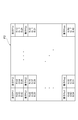
画像データは、例えば、表示装置6の有するm×n個の表示素子のそれぞれに対するR,G,Bのカラー値をフレーム毎に示すデータであり、このカラー値は、表示装置6の個々の表示素子に持たせる反射率又は透過率を示している。図4及び図5に画像データの一例を示す。図4に示す画像データは、時間T1~T2の間の一フレーム(以下、フレームF1という)のR,G,Bのカラー値を表示装置6の表示素子毎に示し、図5に示す画像データは、時間T2~T3の間の一フレーム(以下、フレームF2という)のR,G,Bのカラー値を表示装置6の表示素子毎に示している。例えば、図4に示す時間T1~T2の間の(フレームF1における)素子P11に対するR,G,B毎のカラー値は、それぞれ“12%”,“23%”,“12%”に設定されている。この場合、画像表示制御装置4は、通常動作中であれば、この間の素子P11のR,G,B毎の反射率又は透過率をこのR,G,B毎のカラー値(基準反射率A2又は基準透過率A3に対応)に設定する。また、図5に示す時間T2~T3の間の(フレームF2における)素子P11に対するR,G,B毎のカラー値は、それぞれ、“22%”,“33%”,“42%”に設定されている。この場合、画像表示制御装置4は、通常動作中であれば、この間の素子P11のR,G,B毎の反射率又は透過率をこのR,G,B毎のカラー値(基準反射率A2又は基準透過率A3に対応)に設定する。
次に、図2及び図3を参照して、画像表示制御装置4の構成を説明する。画像表示制御装置4は、図2に示すように、物理的には、CPU41、ROM42、RAM43、通信装置44及び記憶装置45を有しており、これらはバス46に接続されている。CPU41は、ROM42や記憶装置45等の内蔵メモリに格納された所定のコンピュータプログラム(例えば、図6に示すフローチャートの処理を実行するためのコンピュータプログラム)をRAM43にロードして実行することにより、画像表示制御装置4を統括的に制御する。記憶装置45は、書き込み/読み出しが自在なメモリであり、各種コンピュータプログラム及びデータを格納する。通信装置44は、映像入力I/F3、投射用光源5及び表示装置6とデータの送受信を行うためのインターフェイスを有する。
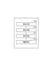
画像表示制御装置4は、図3に示すように、機能的には特定手段41a、算出手段41b、設定手段41c及び制御手段41dを含む。これら図3に示す特定手段41a~制御手段41dは、CPU41がROM42や記憶装置45等の内蔵メモリに格納された上記コンピュータプログラムを実行し、図2に示す画像表示制御装置4の各構成部を動作させることによって実現される機能であり、低消費電力モードの場合に動作する。CPU41は、上記コンピュータプログラムを実行することによって(特に、図3に示す上記特定手段41a~制御手段41dを用いて)、図6のフローチャートに示す画像表示制御装置4の行う処理を実行する。
特定手段41aは、映像入力I/F3から入力された画像データに含まれるR,G,Bのカラー値の最大値を一又は複数フレーム毎に特定する。3板式の場合、特定手段41aは、一又は複数フレーム内におけるR,G,Bの全カラー値のなかから一の最大値を、一又は複数フレーム毎に特定する。単板式の場合、特定手段41aは、一又は複数フレーム内におけるR,G,Bそれぞれの全カラー値のなかからR,G,Bそれぞれの最大値を、一又は複数フレーム毎に特定する。
算出手段41bは、特定手段41aによって特定された最大値を用いて、投射用光源5のフレーム毎の出力時間を基準出力時間A1に基づいて調整するための第1の重みを、一又は複数フレーム毎に算出すると共に、この第1の重みを用いて、表示装置6の反射率又は透過率を画像データに含まれるR,G,Bのカラー値に対応する基準反射率A2又は基準透過率A3に基づいて調整するための第2の重みを、一又は複数フレーム毎に算出する。
3板式の場合、算出手段41bは、一又は複数フレームにおいて特定手段41aによって特定された一の最大値を用いて、当該一又は複数フレームにおける投射用光源5のフレーム毎の出力時間を基準出力値A1に基づいて調整するための第1の重みを算出すると共に、この第1の重みを用いて、当該一又は複数フレームにおける表示装置6の反射率又は透過率を基準反射率A2又は基準透過率A3に基づいて調整するための第2の重みを算出する。この場合、算出手段41bは、特定手段41aによって特定された当該一又は複数フレームにおける一の最大値を、当該一又は複数フレームにおける第1の重みとする算出を行い、この第1の重みの逆数を、当該一又は複数フレームにおける第2の重みとする算出を行う。
一方、単板式の場合、算出手段41bは、一又は複数フレームにおいて特定手段41aによって特定されたR,G,Bそれぞれのカラー値の最大値を用いて、当該一又は複数フレームにおける投射用光源5の一フレーム内のR,G,B毎の出力時間を基準出力値A1に基づいて調整するためのR,G,B毎の第1の重みを算出すると共に、このR,G,B毎の第1の重みを用いて、当該一又は複数フレームにおける表示装置6の反射率又は透過率を基準反射率A2又は基準透過率A3に基づいて調整するためのR,G,B毎の第2の重みを算出する。この場合、算出手段41bは、特定手段41aによって特定された当該一又は複数フレームにおけるR,G,B毎の最大値を、当該一又は複数フレームにおけるR,G,B毎の第1の重みとする算出を行い、このR,G,B毎の第1の重みのそれぞれの逆数を、当該一又は複数フレームにおけるR,G,B毎の第2の重みとする算出を行う。
設定手段41cは、算出手段41bによって算出された第1の重みを基準出力時間A1に乗じた値を、一又は複数フレーム毎の投射用光源5の出力時間に設定する。設定手段41cは、算出手段41bによって算出された第2の重みを表示装置6の基準反射率A2又は基準透過率A3に乗じた値を、当該一又は複数フレームにおける表示装置6の反射率又は透過率に設定する。
3板式の場合、設定手段41cは、算出手段41bによって算出された一又は複数フレームにおける第1の重みを基準出力時間A1に乗じた値を、当該一又は複数フレームにおける投射用光源5のフレーム毎の出力時間に設定する。設定手段41cは、算出手段41bによって算出された当該一又は複数フレームにおける第2の重みを当該一又は複数フレームにおける表示装置6の基準反射率A2又は基準透過率A3に乗じた値を、当該一又は複数フレームにおける表示装置6の反射率又は透過率に設定する。
単板式の場合、設定手段41cは、算出手段41bによって算出された一又は複数フレームにおけるR,G,B毎の第1の重みを基準出力時間A1に乗じた値を、当該一又は複数フレームにおける投射用光源5の一フレーム内のR,G,B毎の出力時間に設定する。設定手段41cは、算出手段41bによって算出された当該一又は複数フレームにおけるR,G,B毎の第2の重みを当該一又は複数フレームにおける表示装置6の基準反射率A2又は基準透過率A3にR,G,B毎に乗じた値を、当該一又は複数フレームにおける表示装置6の反射率又は透過率に設定する。
制御手段41dは、設定手段41cによって設定された投射用光源5の出力時間に基づいて投射用光源5を制御し、設定手段41cによって設定された表示装置6の反射率又は透過率に基づいて表示装置6を制御する。
次に、図4~図6を参照して、本実施形態の動作を説明する。まず、ステップS1において、特定手段41aは、映像入力I/F3から入力された画像データに含まれるR,G,Bのカラー値の最大値を一又は複数フレーム毎に特定する(ステップS1)。例えば、3板式の場合、特定手段41aは、フレームF1におけるR,G,Bのカラー値の最大値を“90%”(素子Pmnにおけるブルー(B)のカラー値)と特定する。さらに、特定手段41aは、フレームF2におけるR,G,Bのカラー値の最大値を“74%”(素子Pm2におけるグリーン(G)のカラー値)と特定する。
一方、単板式の場合、特定手段41aは、フレームF1におけるレッド(R)のカラー値の最大値を“42%”(素子Pm1におけるカラー値)と特定し、グリーン(G)のカラー値の最大値を“81%”(素子Pmnにおけるカラー値)と特定し、ブルー(B)のカラー値の最大値を“90%”(素子Pmnにおけるカラー値)と特定する。さらに、特定手段41aは、フレームF2におけるレッド(R)のカラー値の最大値を“50%”(素子Pmnにおけるカラー値)と特定し、グリーン(G)のカラー値の最大値を“74%”(素子Pm2におけるカラー値)と特定し、ブルー(B)のカラー値の最大値を“54%”(素子Pm1におけるカラー値)と特定する。
ステップS1の後、ステップS2において、算出手段41bは、ステップS1において特定手段41aによって特定された最大値を用いて、投射用光源5の出力時間を基準出力時間A1に基づいて調整するための第1の重みを、一又は複数フレーム毎に算出すると共に、この第1の重みを用いて、表示装置6の反射率又は透過率を基準反射率A2又は基準透過率A3に基づいて調整するための第2の重みを、一又は複数フレーム毎に算出する(ステップS2)。ステップS2において、算出手段41bは、特定手段41aによって特定された最大値を第1の重みとする算出を行い、この第1の重みの逆数を第2の重みとする算出を行う。
例えば、3板式の場合、算出手段41bは、フレームF1におけるカラー値の最大値“90%”を第1の重みとする算出を行い、この第1の重みの逆数“100/90”を第2の重みとする算出を行う。さらに、算出手段41bは、フレームF2におけるカラー値の最大値“74%”を第1の重みとする算出を行い、この第1の重みの逆数“100/74”を第2の重みとする算出を行う。
一方、単板式の場合、算出手段41bは、フレームF1におけるR,G,Bのカラー値の上記各最大値“42%”,“81%”,“90%”をR,G,B毎の第1の重みとする算出を行い、このR,G,B毎の第1の重みの各逆数“100/42”,“100/81”,“100/90”をR,G,B毎の第2の重みとする算出を行う。さらに、算出手段41bは、フレームF2におけるR,G,Bのカラー値の上記各最大値“50%”,“74%”,“54%”をR,G,B毎の第1の重みとする算出を行い、このR,G,B毎の第1の重みの各逆数“100/50”,“100/74”,“100/54”をR,G,B毎の第2の重みとする算出を行う。
ステップS2の後、ステップS3において、設定手段41cは、ステップS2において算出手段41bによって算出された第1の重みを基準出力時間A1に乗じた値を、一又は複数フレーム毎の投射用光源5の出力時間に設定する。そして、設定手段41cは、算出手段41bによって算出されたR,G,B毎の第2の重みを表示装置6のR,G,B毎の基準反射率A2又は基準透過率A3に乗じた値を、一又は複数フレーム毎に、表示装置6のR,G,B毎の反射率又は透過率に設定する(ステップS3)。
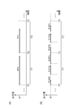
例えば、3板式の場合、ステップS3において、図7(A)に示すように、設定手段41cは、算出手段41bによって算出されたフレームF1における第1の重み“90%”を基準出力時間A1に乗じた値を、フレームF1における投射用光源5の出力時間に設定する。そして、設定手段41cは、算出手段41bによって算出されたフレームF1における第2の重み“100/90”をフレームF1における画像データのカラー値に対応する表示装置6の基準反射率A2又は基準透過率A3に乗じた値を、フレームF1における表示装置6の反射率又は透過率に設定する。さらに、設定手段41cは、算出手段41bによって算出されたフレームF2における第1の重み“74%”を基準出力時間A1に乗じた値を、フレームF2における投射用光源5の出力時間に設定する。そして、設定手段41cは、算出手段41bによって算出されたフレームF2における第2の重み“100/74“をフレームF2における画像データのカラー値に対応する表示装置6の基準反射率A2又は基準透過率A3に乗じた値を、フレームF2における表示装置6の反射率又は透過率に設定する。
一方、単板式の場合、ステップS3において、図7(B)に示すように、設定手段41cは、算出手段41bによって算出されたフレームF1におけるR,G,B毎の第1の重み“42%”,“81%”,“90%”を基準出力時間A1に乗じた値を、フレームF1における投射用光源5のR,G,B毎の出力時間に設定する。そして、設定手段41cは、算出手段41bによって算出されたフレームF1におけるR,G,B毎の第2の重み“100/42”,“100/81”,“100/90”をフレームF1における画像データのカラー値に対応する表示装置6の基準反射率A2又は基準透過率A3にR,G,B毎に乗じた値を、フレームF1における表示装置6の反射率又は透過率に設定する。さらに、設定手段41cは、算出手段41bによって算出されたフレームF2における第1の重み“50%”,“74%”,“54%”を基準出力時間A1に乗じた値を、フレームF2における投射用光源5のR,G,B毎の出力時間に設定する。そして、設定手段41cは、算出手段41bによって算出されたフレームF2におけるR,G,B毎の第2の重み“100/50”,“100/74”,“100/54”をフレームF2における画像データのカラー値に対応する表示装置6の基準反射率A2又は基準透過率A3にR,G,B毎に乗じた値を、フレームF2における表示装置6の反射率又は透過率に設定する。
ステップS3の後、ステップS4において、制御手段41dは、設定手段41cによって設定された投射用光源5の出力時間に基づいて投射用光源5を制御すると共に、設定手段41cによって設定された表示装置6の反射率又は透過率に基づいて表示装置6を制御する(ステップS4)。
次に、実施形態に係る画像表示制御装置4の作用・効果を説明する。画像表示制御装置4は、プロジェクタ1に搭載されており、投射用光源5と、投射用光源5から出力される光を、入力画像データに含まれるカラー値(%)に応じて反射又は透過することによって画像光に変換する表示装置6とを制御する装置である。画像表示制御装置4は、特定手段41a、算出手段41b及び設定手段41cを備える。特定手段41aは、画像データに含まれるカラー値の最大値を一又は複数フレーム毎に特定する。算出手段41bは、特定手段41aによって特定された最大値を用いて、投射用光源5の出力時間を基準出力時間A1に基づいて調整するための第1の重みを一又は複数フレーム毎に算出すると共に、当該第1の重みを用いて、表示装置6の反射率又は透過率をカラー値に対応する基準反射率A2又は基準透過率A3に基づいて調整するための第2の重みを一又は複数フレーム毎に算出する。設定手段41cは、算出手段41bによって算出された第1の重みを基準出力時間A1に乗じた値を、一又は複数フレーム毎の投射用光源5の出力時間に設定し、算出手段41bによって算出された第2の重みを基準反射率A2又は基準透過率A3に乗じた値を、一又は複数フレーム毎の表示装置6の反射率又は透過率に設定する。
よって、カラー値の最大値に基づいて算出された第1の重みを基準出力時間A1に乗じた値を投射用光源5の出力時間に設定されるので、カラー値の最大値が100%未満の場合には投射用光源5の出力時間が低減される。従って、投射用光源5における消費電力も低減される。更に、表示装置6の反射率又は透過率が、第1の重みを用いて算出された第2の重みによって調整されるので、表示装置6から照射される画像光の輝度も、投射用光源5の出力時間に応じて好適に調整可能となる。また、投射用光源5の出力時間が低減されるので、表示装置6の表示素子(素子P11等)において乱反射された漏れ光も低減され、よって、画質が向上する。
更に、算出手段41bは、最大値を第1の重みとし、第1の重みの逆数を第2の重みとするのが好ましい。この場合、表示装置6の反射率又は透過率は、投射用光源5の基準出力時間A1に乗じられた第1の重みの逆数である第2の重みを基準反射率A2又は基準透過率A3に乗じた値とするので、この調整後の表示装置6から照射される画像光の輝度は、投射用光源5の出力時間に基準出力時間A1を用い、且つ、表示装置6の反射率又は透過率に基準反射率A2又は基準透過率A3を用いた場合と同等の輝度を維持できる。
プロジェクタにおいて、投射用光源からの光を効率よく利用できるようにすること。
1…表示装置、2…スクリーン、3…映像入力I/F、4…画像表示制御装置、41…CPU、41a…特定手段、41b…算出手段、41c…設定手段、41d…制御手段、42…ROM、43…RAM、44…通信装置、45…記憶装置、46…バス、5…投射用光源、6…表示装置
Claims (3)
- 投射用光源と、該投射用光源から出力される光を、入力画像データに含まれるカラー値に応じて反射又は透過することによって画像光に変換する表示装置とを制御するプロジェクタの画像表示制御装置であって、
前記入力画像データに含まれる前記カラー値の最大値を一又は複数フレーム毎に特定する特定手段と、
前記特定手段によって特定された前記最大値を用いて、前記投射用光源の出力時間を所定の基準出力時間に基づいて調整するための第1の重みを、前記一又は複数フレーム毎に算出すると共に、当該第1の重みを用いて、前記表示装置の反射率又は透過率を前記カラー値に対応する基準反射率又は基準透過率に基づいて調整するための第2の重みを、前記一又は複数フレーム毎に算出する算出手段と、
前記算出手段によって算出された前記第1の重みを前記基準出力時間に乗じた値を、前記一又は複数フレーム毎の前記投射用光源の出力時間に設定し、前記算出手段によって算出された前記第2の重みを前記基準反射率又は前記基準透過率に乗じた値を、前記一又は複数フレーム毎の前記表示装置の反射率又は透過率に設定する設定手段と
を備える、ことを特徴とする画像表示制御装置。 - 前記算出手段は、前記最大値を前記第1の重みとし、該第1の重みの逆数を前記第2の重みとする、ことを特徴とする請求項1に記載の画像表示制御装置。
- 投射用光源と、該投射用光源から出力される光を、入力画像データに含まれるカラー値に応じて反射又は透過することによって画像光に変換する表示装置とを制御するための制御装置を用いたプロジェクタの画像表示制御方法であって、
前記入力画像データに含まれる前記カラー値の最大値を一又は複数フレーム毎に前記制御装置が特定する特定ステップと、
前記制御装置が、前記特定ステップにおいて特定した前記最大値を用いて、前記投射用光源の出力時間を所定の基準出力時間に基づいて調整するための第1の重みを、前記一又は複数フレーム毎に算出すると共に、当該第1の重みを用いて、前記表示装置の反射率又は透過率を前記カラー値に対応する基準反射率又は基準透過率に基づいて調整するための第2の重みを、前記一又は複数フレーム毎に算出する算出ステップと、
前記制御装置が、前記算出ステップにおいて算出した前記第1の重みを前記基準出力時間に乗じた値を、前記一又は複数フレーム毎の前記投射用光源の出力時間に設定し、前記算出ステップにおいて算出した前記第2の重みを前記基準反射率又は前記基準透過率に乗じた値を、前記一又は複数フレーム毎の前記表示装置の反射率又は透過率に設定する設定ステップと
を備える、ことを特徴とする画像表示制御方法。
Applications Claiming Priority (2)
| Application Number | Priority Date | Filing Date | Title |
|---|---|---|---|
| JP2009-025885 | 2009-02-06 | ||
| JP2009025885A JP2010181694A (ja) | 2009-02-06 | 2009-02-06 | 画像表示制御装置、及び、画像表示制御方法 |
Publications (1)
| Publication Number | Publication Date |
|---|---|
| WO2010089937A1 true WO2010089937A1 (ja) | 2010-08-12 |
Family
ID=42541851
Family Applications (1)
| Application Number | Title | Priority Date | Filing Date |
|---|---|---|---|
| PCT/JP2009/070602 Ceased WO2010089937A1 (ja) | 2009-02-06 | 2009-12-09 | 画像表示制御装置、及び、画像表示制御方法 |
Country Status (2)
| Country | Link |
|---|---|
| JP (1) | JP2010181694A (ja) |
| WO (1) | WO2010089937A1 (ja) |
Families Citing this family (1)
| Publication number | Priority date | Publication date | Assignee | Title |
|---|---|---|---|---|
| CN107547878B (zh) * | 2016-06-24 | 2019-11-08 | 深圳光峰科技股份有限公司 | 投影系统及图像调制方法 |
Citations (2)
| Publication number | Priority date | Publication date | Assignee | Title |
|---|---|---|---|---|
| JP2005049362A (ja) * | 2001-06-04 | 2005-02-24 | Matsushita Electric Ind Co Ltd | 液晶表示装置 |
| JP2006267995A (ja) * | 2005-02-28 | 2006-10-05 | Yamaha Corp | 投射型映像再生装置 |
-
2009
- 2009-02-06 JP JP2009025885A patent/JP2010181694A/ja active Pending
- 2009-12-09 WO PCT/JP2009/070602 patent/WO2010089937A1/ja not_active Ceased
Patent Citations (2)
| Publication number | Priority date | Publication date | Assignee | Title |
|---|---|---|---|---|
| JP2005049362A (ja) * | 2001-06-04 | 2005-02-24 | Matsushita Electric Ind Co Ltd | 液晶表示装置 |
| JP2006267995A (ja) * | 2005-02-28 | 2006-10-05 | Yamaha Corp | 投射型映像再生装置 |
Also Published As
| Publication number | Publication date |
|---|---|
| JP2010181694A (ja) | 2010-08-19 |
Similar Documents
| Publication | Publication Date | Title |
|---|---|---|
| US12155960B2 (en) | Multiple stage modulation projector display systems having efficient light utilization | |
| JP4289269B2 (ja) | 光学表示装置、光学表示装置制御プログラム及び光学表示装置制御方法 | |
| JP5625287B2 (ja) | 光源装置、投影装置、投影方法及びプログラム | |
| US12382002B2 (en) | Temporal modeling of phase modulators in multi-modulation projection | |
| US9286860B2 (en) | Image display device | |
| CN108628070B (zh) | 一种显示系统 | |
| WO2017017758A1 (ja) | プロジェクタ装置、プロジェクタ装置における色補正方法 | |
| WO2010089937A1 (ja) | 画像表示制御装置、及び、画像表示制御方法 | |
| JP2015072480A (ja) | 回転体及び投影装置 | |
| CN111951741B (zh) | 消除残影的方法、装置及存储介质 | |
| JP2010181695A (ja) | 画像表示制御装置、及び、画像表示制御方法 | |
| JP2008233487A (ja) | 光源制御装置 | |
| JP2021105643A (ja) | プロジェクターの動作方法およびプロジェクター | |
| JP5929995B2 (ja) | 回転体および投影装置 | |
| CN211378152U (zh) | 一种能增强对比度的dlp投影仪 | |
| JP5783109B2 (ja) | 画像表示装置 | |
| JP2008026355A (ja) | 光源制御装置 | |
| JP6606634B2 (ja) | 投影装置、制御方法、プログラム及び記憶媒体 | |
| JP5652500B2 (ja) | 光源装置、投影装置、投影方法及びプログラム | |
| JP6291709B2 (ja) | プロジェクター及びその制御方法 | |
| JP2019045551A (ja) | 画像処理装置、表示装置および画像処理装置の制御方法 | |
| JP5637405B2 (ja) | 回転体、投影装置、投影方法およびプログラム | |
| HK40068141A (en) | Temporal modeling of phase modulators in multi-modulation projection | |
| JP2009294265A (ja) | 画像表示装置 | |
| JP2007248598A (ja) | 画像表示制御装置、プロジェクタおよびその制御方法 |
Legal Events
| Date | Code | Title | Description |
|---|---|---|---|
| 121 | Ep: the epo has been informed by wipo that ep was designated in this application |
Ref document number: 09839711 Country of ref document: EP Kind code of ref document: A1 |
|
| NENP | Non-entry into the national phase |
Ref country code: DE |
|
| 122 | Ep: pct application non-entry in european phase |
Ref document number: 09839711 Country of ref document: EP Kind code of ref document: A1 |