WO2010087416A1 - 無線基地局及び通信制御方法 - Google Patents
無線基地局及び通信制御方法 Download PDFInfo
- Publication number
- WO2010087416A1 WO2010087416A1 PCT/JP2010/051171 JP2010051171W WO2010087416A1 WO 2010087416 A1 WO2010087416 A1 WO 2010087416A1 JP 2010051171 W JP2010051171 W JP 2010051171W WO 2010087416 A1 WO2010087416 A1 WO 2010087416A1
- Authority
- WO
- WIPO (PCT)
- Prior art keywords
- quality level
- cqi
- frequency band
- level
- base station
- Prior art date
- Legal status (The legal status is an assumption and is not a legal conclusion. Google has not performed a legal analysis and makes no representation as to the accuracy of the status listed.)
- Ceased
Links
Images



Classifications
-
- H—ELECTRICITY
- H04—ELECTRIC COMMUNICATION TECHNIQUE
- H04L—TRANSMISSION OF DIGITAL INFORMATION, e.g. TELEGRAPHIC COMMUNICATION
- H04L1/00—Arrangements for detecting or preventing errors in the information received
- H04L1/0001—Systems modifying transmission characteristics according to link quality, e.g. power backoff
- H04L1/0023—Systems modifying transmission characteristics according to link quality, e.g. power backoff characterised by the signalling
- H04L1/0026—Transmission of channel quality indication
-
- H—ELECTRICITY
- H04—ELECTRIC COMMUNICATION TECHNIQUE
- H04L—TRANSMISSION OF DIGITAL INFORMATION, e.g. TELEGRAPHIC COMMUNICATION
- H04L1/00—Arrangements for detecting or preventing errors in the information received
- H04L1/0001—Systems modifying transmission characteristics according to link quality, e.g. power backoff
- H04L1/0036—Systems modifying transmission characteristics according to link quality, e.g. power backoff arrangements specific to the receiver
- H04L1/0039—Systems modifying transmission characteristics according to link quality, e.g. power backoff arrangements specific to the receiver other detection of signalling, e.g. detection of TFCI explicit signalling
-
- H—ELECTRICITY
- H04—ELECTRIC COMMUNICATION TECHNIQUE
- H04L—TRANSMISSION OF DIGITAL INFORMATION, e.g. TELEGRAPHIC COMMUNICATION
- H04L1/00—Arrangements for detecting or preventing errors in the information received
- H04L1/0001—Systems modifying transmission characteristics according to link quality, e.g. power backoff
- H04L1/0023—Systems modifying transmission characteristics according to link quality, e.g. power backoff characterised by the signalling
- H04L1/0028—Formatting
- H04L1/0029—Reduction of the amount of signalling, e.g. retention of useful signalling or differential signalling
-
- H—ELECTRICITY
- H04—ELECTRIC COMMUNICATION TECHNIQUE
- H04W—WIRELESS COMMUNICATION NETWORKS
- H04W72/00—Local resource management
- H04W72/50—Allocation or scheduling criteria for wireless resources
- H04W72/54—Allocation or scheduling criteria for wireless resources based on quality criteria
- H04W72/542—Allocation or scheduling criteria for wireless resources based on quality criteria using measured or perceived quality
Definitions
- the present invention relates to a radio base station that assigns a channel to the radio terminal based on CQI fed back from the radio terminal, and a communication control method in the radio base station.
- a wireless base station performs scheduling for assigning a frequency (channel) with good communication quality to a wireless terminal.
- the radio base station assigns a downlink channel to the radio terminal based on a downlink CQI (Channel QualityIndicator) fed back from the radio terminal, and further determines a modulation scheme.
- FDD Frequency Division Duplex
- LTE Long Term Evolution
- BP Bandwidth Part
- SB Sub Band
- the radio base station can acquire only SB-CQIs for some SBs among SBs in one BP. For this reason, when the SB-CQI between wireless terminals competes in the scheduler assignment determination process, the wireless base station must assign a channel corresponding to an SB whose SB-CQI is unknown to a certain wireless terminal. Occurs.
- the wireless terminal actually has a CQI that can select a high modulation scheme.
- a CQI is unknown at the wireless base station, it is necessary to select the lowest-ranking modulation scheme. I don't get it. For this reason, the transmission capacity of the entire system is impaired.
- an object of the present invention is to provide a radio base station and a communication control method capable of appropriately estimating the communication quality level.
- the present invention has the following features.
- a downstream band is divided into a plurality of first frequency bands (BP), and each of the first frequency bands is divided into a plurality of second frequency bands (SB).
- BP first frequency bands
- SB second frequency bands
- a radio base station configured in a radio communication system, wherein the highest communication among the communication qualities of the plurality of second frequency bands in the first frequency band for each first frequency band.
- the reception unit (CQI information reception unit 120) that receives the first quality level (SB-CQI) indicating the quality from the wireless terminals (wireless terminals 2A to 2C) and the first frequency band in each of the adjacent first frequency bands
- An interpolation unit (missing CQI interpolation unit 140) that interpolates a second quality level indicating communication quality in a frequency band (missing SB) between the second frequency bands corresponding to the quality level, and the interpolating unit is adjacent to the second quality level.
- the first frequency band Of the frequency bands between the second frequency bands corresponding to the first quality level in each of the first frequency bands to which the second frequency band corresponding to the first quality level of the lower level belongs The portion is set to the second quality level that is lower than the first quality level of the lower level, and the first frequency band to which the second frequency band corresponding to the first quality level of the higher level belongs About this part, it makes it a summary to set it as the said 2nd quality level below the said 1st quality level of the said higher level.
- Such a radio base station receives, for each first frequency band, a first quality level indicating the highest communication quality from among a plurality of second frequency bands in the first frequency band from the radio terminal, and When interpolating the second quality level indicating the communication quality of the frequency band between the second frequency bands corresponding to the first quality level in each of the matching first frequency bands, in each of the adjacent first frequency bands Of the frequency bands between the second frequency bands corresponding to the first quality level, the lower one of the levels of the first frequency band to which the second frequency band corresponding to the lower first quality level belongs. For the portion of the first frequency band to which the second frequency band corresponding to the first quality level of the higher level belongs, the first quality of the higher level level The second quality level which is below.
- the communication quality of the portion of the first frequency band to which the second frequency band corresponding to the first quality level of the lower level belongs cannot exceed the first quality level of the lower level.
- the communication quality of the portion of the first frequency band to which the second frequency band corresponding to the higher first quality level belongs cannot exceed the higher first quality level.
- the second communication level for the portion of the first frequency band to which the second frequency band corresponding to the first quality level of the lower level belongs is set to be equal to or lower than the first quality level of the lower level,
- the communication quality is appropriately set. Can be estimated.
- a second feature of the present invention relates to the first feature, wherein the interpolating unit includes a frequency band between the second frequency bands corresponding to the first quality level in each of the adjacent first frequency bands.
- the interpolating unit includes a frequency band between the second frequency bands corresponding to the first quality level in each of the adjacent first frequency bands.
- the second corresponding to the first quality level of the higher level is that the level becomes higher as the frequency band is closer.
- a third feature of the present invention relates to the first feature or the second feature, wherein the reception unit receives a first quality level indicating an average communication quality in the downlink band, and the interpolation unit receives the downlink
- the second frequency band corresponding to the first quality level in the first frequency band including the band edge that is one of the start end and the end of the band does not include the band end; and
- the band edge corresponds to the first quality level.
- the gist is that the fourth quality level indicating the communication quality of the frequency band between the second frequency band is a level between the first quality level and the third quality level.
- a fourth feature of the present invention relates to any one of the first feature to the third feature, and is based on the first quality level and the second quality level, with respect to the radio base station.
- the gist of the present invention is to provide an allocation unit that allocates a frequency band in the downlink direction.
- a fifth feature of the present invention relates to any one of the first feature to the fourth feature, wherein the interpolating unit is an elapsed time after receiving the first quality level from the radio base station. Accordingly, the gist is to reduce the first quality level.
- a radio configured in a radio communication system in which a downlink band is divided into a plurality of first frequency bands, and each of the first frequency bands is divided into a plurality of second frequency bands.
- a communication control method in a base station wherein the radio base station has a third quality level indicating an average communication quality in the downlink band, and the plurality of second frequencies in the first frequency band for each of the first frequency bands.
- the portion of the first frequency band to which the second frequency band corresponding to the lower first quality level belongs. Is a portion of the first frequency band to which the second frequency band corresponding to the first quality level of the higher level belongs to the second quality level which is lower than the first quality level of the lower level
- the gist is that the second quality level is lower than the first quality level of the higher level.
- the present invention it is possible to provide a radio base station and a communication control method capable of appropriately estimating the communication quality level.
- FIG. 1 is an overall schematic configuration diagram of a radio communication system according to an embodiment of the present invention.
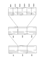
- FIG. 2 is a diagram illustrating an example of a downlink frequency band according to the embodiment of the present invention.
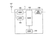
- FIG. 3 is a schematic configuration diagram of a radio base station according to the embodiment of the present invention.
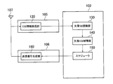
- FIG. 4 is a functional block configuration diagram of a control unit, a reception unit, and a transmission unit in the radio base station according to the embodiment of the present invention.
- FIG. 5 is a functional block diagram of the missing CQI interpolation unit according to the embodiment of the present invention.
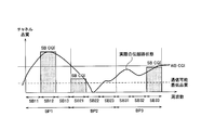
- FIG. 6 is a diagram illustrating an example of SB-CQI received by the radio base station according to the embodiment of the present invention.
- FIG. 7 is a diagram illustrating an example of interpolation by the missing CQI interpolation unit according to the embodiment of the present invention.
- FIG. 8 is a schematic configuration diagram of a radio terminal according to the embodiment of the present invention.
- FIG. 9 is a functional block configuration diagram of the wireless terminal according to the embodiment of the present invention.
- FIG. 10 is a flowchart showing an operation of the radio base station according to the embodiment of the present invention.
- FIG. 1 is an overall schematic configuration diagram of a radio communication system 10 according to an embodiment of the present invention.
- the radio communication system 10 is an LTE (Long Term Evolution) radio communication system which is a 3.9G communication system.
- the radio communication system 10 includes a radio base station 1, a radio terminal 2A, a radio terminal 2B, and a radio terminal 2C.
- radio terminals 2A to 2C are located in a cell 3 provided by the radio base station 1.
- the downlink frequency band (downlink band) in the wireless communication system 10 is divided into units called BP (Bandwidth-Part).
- BP is divided into units called SB (Sub Band), and SB is further divided into RB (Resouce Block).
- FIG. 3 is a schematic configuration diagram of the radio base station 1. As illustrated in FIG. 3, the radio base station 1 includes a control unit 102, a storage unit 103, a wired communication unit 104, a reception unit 105, a transmission unit 106, and an antenna 107.
- the radio base station 1 includes a control unit 102, a storage unit 103, a wired communication unit 104, a reception unit 105, a transmission unit 106, and an antenna 107.
- the control unit 102 is constituted by a CPU, for example, and controls various functions provided in the radio base station 1.
- the storage unit 103 is configured by a memory, for example, and stores various types of information used for control and the like in the radio base station 1.
- the wired communication unit 104 is connected to an access gateway or the like existing in the upper network via a router or the like (not shown).
- the receiving unit 105 receives wireless signals from the wireless terminals 2A to 2C via the antenna 107.
- the transmitting unit 106 transmits a radio signal to the radio terminals 2A to 2C via the antenna 107.
- FIG. 4 is a functional block configuration diagram of the control unit 102, the reception unit 105, and the transmission unit 106.
- the control unit 102 includes a missing SB recognition unit 130, a missing CQI interpolation unit 140, and a scheduler 150.
- the receiving unit 105 includes a CQI information receiving unit 120, and the transmitting unit 106 includes a transmission signal generating unit 160.
- the radio base station 1 communicates with the radio terminal 2A. However, the same applies when the radio base station 1 communicates with the radio terminal 2B and the radio terminal 2C.
- the CQI information receiving unit 120 receives the CQI notification transmitted from the wireless terminal 2A.
- the CQI notification includes a CQI (hereinafter referred to as SB-CQI) for an SB having the highest CQI (Channel Quality Indicator) in each BP, and an SB ID (SB-ID) corresponding to the SB-CQI.
- the CQI information receiving unit 120 outputs the CQI notification to the missing SB recognition unit 130.
- the missing SB recognition unit 130 determines whether there is an SB for which CQI is not notified, based on the SB ID included in the CQI notification input from the CQI information receiving unit 120. When there is an SB for which CQI is not notified, the SB is recognized as a missing SB. Specifically, the missing SB recognition unit 130 recognizes SBs having SB-IDs between SB-IDs corresponding to SB-CQIs in adjacent BPs included in the CQI notification as missing SBs.
- the missing SB recognition unit 130 If there is a missing SB, the missing SB recognition unit 130 outputs a CQI notification to the missing CQI interpolation unit 140.
- the missing CQI interpolation unit 140 uses the SB-CQI included in the CQI notification input from the missing CQI interpolation unit 140 to interpolate the CQI of the missing SB.
- FIG. 5 is a functional block diagram of the missing CQI interpolation unit 140.
- the missing CQI interpolation unit 140 includes a CQI comparison unit 142 and a CQI interpolation unit 144.
- the CQI comparison unit 142 inputs the SB-CQI for each BP from the missing SB recognition unit 130. Next, CQI comparison section 142 compares SB-CQIs in each of adjacent BPs. Further, CQI comparison section 142 outputs the result of comparing SB-CQI in each of adjacent BPs to CQI interpolation section 144.
- the CQI interpolation unit 144 uses the comparison result input from the CQI comparison unit 142 and the SB-CQI in each of the adjacent BPs to be compared, and the frequency band between SBs corresponding to these SB-CQIs (hereinafter referred to as SB-CQI). , CQI of missing SB existing in the interpolation frequency band) is interpolated.
- the CQI interpolation unit 144 sets the CQI of the missing SB existing in the interpolation frequency band in the BP to which the SB corresponding to the SB-CQI having the lower level belongs to be equal to or lower than the SB-CQI having the lower level. To do. Further, the CQI interpolation unit 144 sets the CQI of the missing SB present in the interpolation frequency band in the BP to which the SB corresponding to the SB-CQI having the higher level is equal to or lower than the SB-CQI having the higher level, and The higher the level is, the closer to the SB corresponding to the SB-CQI of the higher level.
- the CQI interpolation unit 144 outputs the CQI notification and the CQI of the missing SB to the scheduler 150.
- FIG. 6 is a diagram illustrating an example of the SB-CQI received by the wireless base station 1 from the wireless terminal 2A.
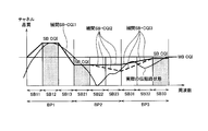
- FIG. 7 is a diagram illustrating an example of the CQI interpolation of the missing SB by the missing CQI interpolation unit 140 in the case of FIG.
- the downstream frequency band in the wireless communication system 10 is divided into BP1, BP2, and BP3. Further, BP1 is divided into SB11, SB12 and SB13, BP2 is divided into SB21, SB22 and SB23, and BP3 is divided into SB31, SB32 and SB33.
- the radio base station 1 receives the CQI of SB12 in BP1, the CQI of SB21 in BP2, and the CQI of SB33 in BP3 as SB-CQI corresponding to each BP.
- the missing SB recognition unit 130 recognizes SB13, SB22, SB23, SB31, and SB32 corresponding to the CQI not received as missing SB.
- the CQI comparison unit 142 outputs a comparison result indicating that the SB-12 CQI is higher for the adjacent BP1 and BP2 to the CQI interpolation unit 144.
- the CQI interpolation unit 144 linearly interpolates between SB12 and SB21 based on the comparison result, thereby eliminating SB13 that is a missing SB present in the interpolation frequency band belonging to BP1.
- the CQI is made higher as it is lower than the SB-12 corresponding to the SB-CQI corresponding to the BP1 and closer to the SB12 corresponding to the higher SB-CQI (FIG. 7). Interpolation SB-CQI1).
- the CQI comparison unit 142 outputs a comparison result indicating that the SB-CQI corresponding to BP3 is higher for the adjacent BP2 and BP3 to the CQI interpolation unit 144.
- the CQI interpolation unit 144 converts the CQIs of SB13 and SB14, which are missing SBs in the interpolation frequency band belonging to BP2, to the SB-CQI corresponding to BP2. It is the same as the CQI of a certain SB-21 (interpolation SB-CQI2 in FIG. 7). Further, the CQI interpolation unit 144 performs linear interpolation between SB23 and SB33 based on the comparison result, so that the CQI of SB31 and SB32 that are missing SBs in the interpolation frequency band belonging to BP3 corresponds to BP3.
- the SB-CQI of SB-33 that is equal to or less than the SB-CQI to be performed (SBI-CQI3 in FIG. 7).
- the CQI interpolation unit 144 outputs the CQI notification and the interpolated CQIs of SB13, SB22, SB23, SB31, and SB32 to the scheduler 150.
- control unit 102 the reception unit 105, and the transmission unit 106 will be described.
- the scheduler 150 allocates a channel to the wireless terminal 2A using the CQI notification input from the CQI interpolation unit 144 and the CQI of the determined missing SB.
- the transmission signal generation unit 160 generates a transmission signal for notifying the channel information assigned by the scheduler 150 to the wireless terminal 2A.
- the transmission signal generation unit 160 transmits the generated transmission signal to the wireless terminal 2A.
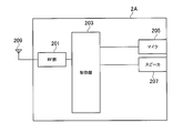
- FIG. 8 is a schematic configuration diagram of the radio terminal 2A.
- the radio base station 2B and the radio base station 2C have the same configuration.
- the wireless terminal 2A is, for example, a voice terminal, and includes an RF unit 201, a control unit 203, a microphone 205, a speaker 207, and an antenna 209.
- the RF unit 201 includes an RF circuit, a baseband circuit, and the like, performs modulation and demodulation, encoding and decoding, and transmits and receives a radio signal via the antenna 209.
- the control unit 203 is configured by a CPU, for example, and controls various functions provided in the wireless terminal 2.
- the microphone 205 collects sound and outputs sound data based on the collected sound to the control unit 203.
- the speaker 207 outputs sound based on the sound data acquired from the control unit 203.
- FIG. 9 is a functional block configuration diagram of the control unit 203.
- the control unit 203 includes a CQI calculation unit 230 and an SB-CQI selection unit 232.
- the CQI calculation unit 230 calculates the CQI in each SB based on the radio signal received by the RF unit 201 via the antenna 209. In addition, CQI calculation section 230 calculates WB-CQI based on the received radio signal. The CQI calculation unit 230 outputs the CQI and WB-CQI of each SB to the SB-CQI selection unit 232.
- the SB-CQI selection unit 232 inputs from the CQI calculation unit 230. Further, for each BP, the SB-CQI selection unit 232 selects the highest CQI among the SB CQIs in the BP as the SB-CQI. The SB-CQI selection unit 232 generates a CQI notification including the SB-CQI and the WB-CQI in each BP. The SB-CQI selection unit 232 outputs the generated CQI notification to the RF unit 201.
- the RF unit 201 transmits a CQI notification to the radio base station 1.
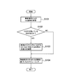
- FIG. 10 is a flowchart showing the operation of the radio base station 1 in the radio communication system 10.
- step S101 the CQI information receiving unit 120 of the radio base station 1 receives a CQI notification from the radio terminal 2A.
- step S102 the missing SB recognition unit 130 of the radio base station 1 determines whether there is an SB (missing SB) from which CQI is missing.
- step S103 the missing CQI interpolation unit 140 of the radio base station 1 interpolates a missing SB between SBs corresponding to SB-CQI in each of the adjacent BPs.
- step S102 If there is no missing SB (NO in step S102), the process proceeds to step S104.
- step S104 the scheduler 150 of the radio base station 1 performs scheduling based on the CQI of all SBs of the radio terminal 2A. Specifically, a channel determined based on the CQI of all SBs is allocated to the wireless terminal 2A.
- the missing CQI interpolation unit 140 has the lower level of the interpolation frequency bands between SBs corresponding to SB-CQIs in each of adjacent BPs.
- the CQI of the missing SB existing in the interpolation frequency band in the BP to which the SB corresponding to the SB-CQI belongs is set to be equal to or lower than the SB-CQI having the lower level.
- the CQI interpolation unit 144 sets the CQI of the missing SB existing in the interpolation frequency band in the BP to which the SB corresponding to the higher level SB-CQI belongs to be equal to or lower than the higher level SB-CQI.
- the CQI of the interpolation frequency band in the BP to which the SB corresponding to the SB-CQI having the lower level belongs cannot exceed the SB-CQI having the lower level.
- the CQI of the interpolation frequency band in the BP to which the SB corresponding to the higher level SB-CQI belongs cannot exceed the higher level SB-CQI.
- the radio base station 1 sets the CQI of the interpolation frequency band in the BP to which the SB corresponding to the SB-CQI having the lower level belongs to be equal to or lower than the SB-CQI having the lower level. Also, the radio base station 1 has the CQI of the interpolation frequency band in the BP to which the SB corresponding to the higher level SB-CQI belongs is equal to or lower than the higher level SB-CQI and has a higher level. The closer to SB12 corresponding to the other SB-CQI, the higher the CQI. Thereby, communication quality can be estimated appropriately.
- the radio base station 1 allocates a channel to a radio terminal using the interpolated missing SB CQI and the CQI notification. For this reason, the radio base station 1 can appropriately perform scheduling even when the missing SB exists and the missing SB must be assigned to the wireless terminal.
- the CQI notification may further include the average (hereinafter referred to as WB-CQI) of the downlink CQI in the wireless communication system 10.
- WB-CQI the average
- the CQI interpolation unit 144 sets the CQI of the interpolation frequency band to a level between SB-CQI and WB-CQI.
- the CQI interpolation unit 144 may measure an elapsed time after the CQI notification is received. Further, the CQI interpolation unit 144 may decrease the SB-CQI included in the CQI notification as the elapsed time is longer.
- the SB-CQI included in the CQI notification is more likely to deviate from the current SB-CQI.
- the current SB-CQI is likely to be lower than the SB-CQI included in the CQI notification as the elapsed time from the reception of the CQI notification becomes longer.
- the CQI interpolation unit 144 reduces the SB-CQI included in the CQI notification as the elapsed time from the reception of the CQI becomes longer, so that an appropriate difference considering the current SB-CQI is taken into account. SB-CQI can be set.
- the radio base station and the communication control method according to the present invention can appropriately estimate the level of communication quality, and are useful as the radio base station and the communication control method.
Landscapes
- Engineering & Computer Science (AREA)
- Quality & Reliability (AREA)
- Computer Networks & Wireless Communication (AREA)
- Signal Processing (AREA)
- Mobile Radio Communication Systems (AREA)
Abstract
無線基地局1は、BP毎に、BPにおける複数のSBのCQIのうち、最高 のCQIであるSB-CQIを無線端末から受信する。更に無線基地局1は、隣り合うBPのそれぞれにおける、SB-CQIに対応するSBの間の欠落SBのCQIを、レベルが低い方のSB-CQIに対応するSBが属するBPの部分については、低い方のSB-CQI以下とし、レベルが高い方のSB-CQIに対応するSBが属するBPの部分については、レベルが高い方のSB-CQI以下とする。
Description
本発明は、無線端末からフィードバックされるCQIに基づいて当該無線端末にチャネルを割り当てる無線基地局、及び、当該無線基地局における通信制御方法に関する。
周波数分割複信(FDD:Frequency Division Duplex)を用いる無線通信システムにおいて、無線基地局は、通信品質の良好な周波数(チャネル)を無線端末に割り当てるスケジューリングを行っている。この時、無線基地局は、無線端末からフィードバックされる下り方向のCQI(Channel Quality Indicator)に基づいて、当該無線端末に下り方向のチャネルを割り当てており、さらに、変調方式を決定している。
3.9G通信システムであるLTE(Long Term Evolution)では、システムの周波数帯域はBP(Bandwidth Part)と称される単位に分割され、さらにBPはSB(Sub Band)と称される単位に分割される。このLTEにおいて、Periodic Feedback モードでは、フィードバック量を少なくして上り方向のチャネルを効率的に利用するために、無線端末は、1つのBPにおいて、CQIが最も高いSBについてのみ、そのSBのCQI(SB-CQI)を、無線基地局にフィードバックしている。また、無線端末は、システムの周波数帯域の平均的なCQI(WB-CQI)をフィードバックしている。
しかし、このような無線通信システムにおいては、無線基地局は、1つのBP内のSBのうち、一部のSBについてのSB-CQIしか取得することができない。このため、スケジューラの割り当て決定過程において、無線端末同士のSB-CQIが競合した場合、無線基地局は、ある無線端末に対してSB-CQIが不明のSBに対応するチャネルを割り当てなければならない状況が生じる。
この場合、無線端末に割り当てられた下り方向のSBについてのSB-CQIが通信不能なほど低い場合、下り方向の通信は困難となる。
また、無線端末側では、実際には高い変調方式を選択することができるCQIを持っているが、無線基地局ではこのようなCQIは不明であるため、最低ランクの変調方式を選択せざるを得ない。このため、システム全体の伝送容量が損なわれてしまう。
そこで、本発明は、通信品質のレベルを適切に推定することが可能な無線基地局及び通信制御方法を提供することを目的とする。
上述した課題を解決するために、本発明は以下のような特徴を有している。まず、本発明の第1の特徴は、下り帯域が、複数の第1周波数帯(BP)に分割され、前記第1周波数帯のそれぞれが複数の第2周波数帯(SB)に分割されている無線通信システムに構成される無線基地局(無線基地局1)であって、前記第1周波数帯毎に、前記第1周波数帯における前記複数の第2周波数帯の通信品質のうち、最高の通信品質を示す第1品質レベル(SB-CQI)を無線端末(無線端末2A~2C)から受信する受信部(CQI情報受信部120)と、隣り合う前記第1周波数帯のそれぞれにおける、前記第1品質レベルに対応する前記第2周波数帯の間の周波数帯(欠落SB)の通信品質を示す第2品質レベルを補間する補間部(欠落CQI補間部140)とを備え、前記補間部は、隣り合う前記第1周波数帯のそれぞれにおける前記第1品質レベルに対応する前記第2周波数帯の間の周波数帯のうち、レベルの低い方の前記第1品質レベルに対応する前記第2周波数帯が属する前記第1周波数帯の部分については、前記レベルの低い方の前記第1品質レベル以下である前記第2品質レベルとし、レベルの高い方の前記第1品質レベルに対応する前記第2周波数帯が属する前記第1周波数帯の部分については、前記レベルの高い方の前記第1品質レベル以下である前記第2品質レベルとすることを要旨とする。
このような無線基地局は、第1周波数帯毎に、第1周波数帯における複数の第2周波数帯の通信品質のうち、最高の通信品質を示す第1品質レベルを無線端末から受信し、隣り合う前記第1周波数帯のそれぞれにおける、第1品質レベルに対応する第2周波数帯の間の周波数帯の通信品質を示す第2品質レベルを補間する際に、隣り合う第1周波数帯のそれぞれにおける第1品質レベルに対応する第2周波数帯の間の周波数帯のうち、レベルの低い方の第1品質レベルに対応する第2周波数帯が属する第1周波数帯の部分については、レベルの低い方の第1品質レベル以下である前記第2品質レベルとし、レベルの高い方の第1品質レベルに対応する第2周波数帯が属する第1周波数帯の部分については、レベルの高い方の第1品質レベル以下である第2品質レベルとする。
レベルの低い方の第1品質レベルに対応する第2周波数帯が属する第1周波数帯の部分の通信品質は、レベルの低い方の第1品質レベルを超えるとなることはあり得ない。同様に、レベルの高い方の第1品質レベルに対応する第2周波数帯が属する第1周波数帯の部分の通信品質は、レベルの高い方の第1品質レベルを超えることはあり得ない。
このため、レベルの低い方の第1品質レベルに対応する第2周波数帯が属する第1周波数帯の部分についての第2通信レベルを、当該レベルの低い方の第1品質レベル以下とし、レベルの高い方の第1品質レベルに対応する第2周波数帯が属する第1周波数帯の部分についての第2通信レベルを、当該レベルの高い方の第1品質レベル以下とすることにより、通信品質を適切に推定することができる。
本発明の第2の特徴は、第1の特徴に係り、前記補間部は、隣り合う前記第1周波数帯のそれぞれにおける前記第1品質レベルに対応する前記第2周波数帯の間の周波数帯のうち、前記レベルの高い方の前記第1品質レベルに対応する前記第2周波数帯が属する前記第1周波数帯の部分については、前記レベルの高い方の前記第1品質レベルに対応する前記第2周波数帯に近いほどレベルが高くなる前記第2品質レベルとするを要旨とする。
本発明の第3の特徴は、第1の特徴または第2の特徴に係り、前記受信部は、前記下り帯域における平均通信品質を示す第1品質レベルを受信し、前記補間部は、前記下り帯域の始端及び終端のうち何れか一方である帯域端を含む前記第1周波数帯における前記第1品質レベルに対応する前記第2周波数帯域が、前記帯域端を含まない場合であり、且つ、前記帯域端を含む前記第1周波数帯に対応する前記第1品質レベルが、前記下り帯域における平均通信品質を示す第3品質レベルよりも高い場合、前記帯域端と、前記第1品質レベルに対応する前記第2周波数帯域との間の周波数帯の通信品質を示す第4品質レベルを、前記第1品質レベルと前記第3品質レベルとの間のレベルとするを要旨とする。
本発明の第4の特徴は、第1の特徴乃至第3の特徴のうち何れか1つに係り、前記第1品質レベルと、前記第2品質レベルとに基づいて、前記無線基地局に対して、下り方向の周波数帯を割り当てる割当部を備えることを要旨とする。
本発明の第5の特徴は、第1の特徴乃至第4の特徴のうち何れか1つに係り、前記補間部は、前記無線基地局から前記第1品質レベルを受信してからの経過時間に応じて、前記第1品質レベルを低下させることを要旨とする。
本発明の第6の特徴は、下り帯域が、複数の第1周波数帯に分割され、前記第1周波数帯のそれぞれが複数の第2周波数帯に分割されている無線通信システムに構成される無線基地局における通信制御方法であって、前記無線基地局が、前記下り帯域における平均通信品質を示す第3品質レベルと、前記第1周波数帯毎に、前記第1周波数帯における前記複数の第2周波数帯の通信品質のうち、最高の通信品質を示す第1品質レベルとを無線端末から受信するステップと、前記無線基地局が、隣り合う前記第1周波数帯のそれぞれにおける、前記第1品質レベルに対応する前記第2周波数帯の間の周波数帯の通信品質を示す第2品質レベルを補間するステップとを備え、前記補間するステップは、隣り合う前記第1周波数帯のそれぞれにおける前記第1品質レベルに対応する前記第2周波数帯の間の周波数帯のうち、レベルの低い方の前記第1品質レベルに対応する前記第2周波数帯が属する前記第1周波数帯の部分については、前記レベルの低い方の前記第1品質レベル以下である前記第2品質レベルとし、レベルの高い方の前記第1品質レベルに対応する前記第2周波数帯が属する前記第1周波数帯の部分については、前記レベルの高い方の前記第1品質レベル以下である前記第2品質レベルとすることを要旨とする。
本発明によれば、通信品質のレベルを適切に推定することが可能な無線基地局及び通信制御方法を提供できる。
次に、図面を参照して、本発明の実施形態を説明する。具体的には、(1)無線通信システムの構成、(2)無線基地局の動作、(3)作用・効果、(4)その他の実施形態について説明する。以下の実施形態における図面の記載において、同一又は類似の部分には同一又は類似の符号を付している。
(1)無線通信システムの構成
まず、本発明の実施形態に係る無線通信システムの構成について、(1.1)無線通信システムの全体概略構成、(1.2)無線基地局の構成、(1.3)無線端末の構成の順に説明する。
まず、本発明の実施形態に係る無線通信システムの構成について、(1.1)無線通信システムの全体概略構成、(1.2)無線基地局の構成、(1.3)無線端末の構成の順に説明する。
(1.1)無線通信システムの全体概略構成
図1は、本発明の実施形態に係る無線通信システム10の全体概略構成図である。
図1は、本発明の実施形態に係る無線通信システム10の全体概略構成図である。
図1に示すように、無線通信システム10は、3.9G通信システムであるLTE(Long Term Evolution)の無線通信システムである。この無線通信システム10は、無線基地局1と、無線端末2A、無線端末2B及び無線端末2Cとを含む。図1において、無線端末2A乃至2Cは、無線基地局1が提供するセル3に在圏している。
図2に示すように、無線通信システム10における下り方向の周波数帯域(下り帯域)は、BP(Bandwidth Part)と称される単位に分割される。また、BPはSB(Sub Band)と称される単位に分割され、さらにSBはRB(Resouce Block)に分割される。
(1.2)無線基地局の構成
次に、無線基地局1の構成について、(1.2.1)無線基地局の概略構成、(1.2.2)無線基地局の詳細構成の順に説明する。
次に、無線基地局1の構成について、(1.2.1)無線基地局の概略構成、(1.2.2)無線基地局の詳細構成の順に説明する。
(1.2.1)無線基地局の概略構成
図3は、無線基地局1の概略構成図である。図3に示すように、無線基地局1は、制御部102、記憶部103、有線通信部104、受信部105、送信部106、アンテナ107を含む。
図3は、無線基地局1の概略構成図である。図3に示すように、無線基地局1は、制御部102、記憶部103、有線通信部104、受信部105、送信部106、アンテナ107を含む。
制御部102は、例えばCPUによって構成され、無線基地局1が具備する各種機能を制御する。記憶部103は、例えばメモリによって構成され、無線基地局1における制御などに用いられる各種情報を記憶する。有線通信部104は、図示しないルータ等を介して上位ネットワークに存在するアクセスゲートウェイ等に接続される。
受信部105は、アンテナ107を介して、無線端末2A乃至2Cからの無線信号を受信する。送信部106は、アンテナ107を介して、無線端末2A乃至2Cへ無線信号を送信する。
(1.2.2)無線基地局の詳細構成
次に、無線基地局1の詳細構成、具体的には、制御部102、受信部105、及び送信部106の機能ブロック構成について説明する。図4は、制御部102、受信部105、及び送信部106の機能ブロック構成図である。図4において、制御部102は、欠落SB認識部130、欠落CQI補間部140、及びスケジューラ150を含む。また、受信部105は、CQI情報受信部120を含み、送信部106は送信信号生成部160を含む。
次に、無線基地局1の詳細構成、具体的には、制御部102、受信部105、及び送信部106の機能ブロック構成について説明する。図4は、制御部102、受信部105、及び送信部106の機能ブロック構成図である。図4において、制御部102は、欠落SB認識部130、欠落CQI補間部140、及びスケジューラ150を含む。また、受信部105は、CQI情報受信部120を含み、送信部106は送信信号生成部160を含む。
以下においては、無線基地局1が、無線端末2Aと通信を行うものとして説明する。但し、無線基地局1が、無線端末2B及び無線端末2Cと通信を行う場合も同様である。
CQI情報受信部120は、無線端末2Aから送信されたCQI通知を受信する。CQI通知は、BPのそれぞれにおいて、CQI(Channel Quality Indicator)が最も高いSBについてのCQI(以下、SB-CQI)と、SB-CQIに対応するSBのID(SB-ID)とを含む。CQI情報受信部120は、CQI通知を欠落SB認識部130に出力する。
欠落SB認識部130は、CQI情報受信部120から入力したCQI通知に含まれるSBのIDに基づいて、CQIの通知されていないSBが存在するか否かを判断する。CQIが通知されていないSBが存在する場合、当該SBを欠落SBとして認識する。具体的には、欠落SB認識部130は、CQI通知に含まれる隣り合うBPのそれぞれにおけるSB-CQIに対応するSB-IDの間のSB-IDを有するSBを、欠落SBとして認識する。
欠落SBが存在する場合、欠落SB認識部130は、欠落CQI補間部140へCQI通知を出力する。
欠落CQI補間部140は、欠落CQI補間部140から入力したCQI通知に含まれるSB-CQIを用いて、欠落SBのCQIを補間する。
図5は、欠落CQI補間部140機能ブロック図である。欠落CQI補間部140は、CQI比較部142及びCQI補間部144を含む。
CQI比較部142は、欠落SB認識部130からBP毎のSB-CQIを入力する。次に、CQI比較部142は、隣り合うBPのそれぞれにおけるSB-CQI同士を比較する。さらに、CQI比較部142は、隣り合うBPのそれぞれにおけるSB-CQIを比較した結果を、CQI補間部144に出力する。
CQI補間部144は、CQI比較部142から入力した比較結果と、比較対象である隣り合うBPのそれぞれにおけるSB-CQIとを用いて、これらSB-CQIに対応するSBの間の周波数帯(以下、補間周波数帯)に存在する欠落SBのCQIを補間する。
具体的には、CQI補間部144は、レベルの低い方のSB-CQIに対応するSBが属するBP内の補間周波数帯に存在する欠落SBのCQIを、レベルの低い方のSB-CQI以下とする。また、CQI補間部144は、レベルの高い方のSB-CQIに対応するSBが属するBP内の補間周波数帯に存在する欠落SBのCQIを、レベルの高い方のSB-CQI以下であり、且つ、レベルの高い方のSB-CQIに対応するSBに近いほどレベルが高くなるようにする。
そして、CQI補間部144は、CQI通知と欠落SBのCQIとをスケジューラ150に出力する。
図6は、無線基地局1が無線端末2Aから受信したSB-CQIの一例を示す図である。また、図7は、図6の場合における欠落CQI補間部140による欠落SBのCQIの補間の一例を示す図である。
図6において、無線通信システム10における下り方向の周波数帯域は、BP1、BP2及びBP3に分割されている。さらに、BP1は、SB11、SB12及びSB13に、BP2は、SB21,SB22及びSB23に、BP3は、SB31、SB32及びSB33にそれぞれ分割されている。
無線基地局1は、BP1におけるSB12のCQI、BP2におけるSB21のCQI、BP3におけるSB33のCQIを、各BPに対応するSB-CQIとして受信している。このとき、欠落SB認識部130は、受信していないCQIに対応するSB13、SB22、SB23、SB31、及びSB32を、欠落SBとして認識する。
図6では、BP1とBP2とが隣接している。更に、SB-CQIであるSB-12のCQIは、SB-CQIであるSB-21のCQIよりも高い。このため、CQI比較部142は、隣り合うBP1及びBP2について、SB-12のCQIの方が高いことを示す比較結果をCQI補間部144に出力する。
この場合、図7に示すように、CQI補間部144は、比較結果に基づいて、SB12とSB21との間を線形補間することにより、BP1に属する補間周波数帯に存在する欠落SBであるSB13のCQIについて、BP1に対応するSB-CQIであるSB-12のCQI以下であり、且つ、レベルが高い方のSB-CQIに対応するSB12に近いほど、CQIが高くなるようにする(図7の補間SB-CQI1)。
また、図6では、BP2とBP3とが隣接している。更に、BP2に対応するSB-CQIであるSB-21のCQIは、BP3に対応するSB-CQIであるSB-33のCQIよりも高い。このため、CQI比較部142は、隣り合うBP2及びBP3について、BP3に対応するSB-CQIの方が高いことを示す比較結果をCQI補間部144に出力する。
この場合、図7に示すように、CQI補間部144は、比較結果に基づいて、BP2に属する補間周波数帯に存在する欠落SBであるSB13及びSB14のCQIを、BP2に対応するSB-CQIであるSB-21のCQIと同一にする(図7の補間SB-CQI2)。また、CQI補間部144は、比較結果に基づいて、SB23とSB33との間を線形補間することにより、BP3に属する補間周波数帯に存在する欠落SBであるSB31及びSB32のCQIについて、BP3に対応するSB-CQIであるSB-33のCQI以下とする(図7のSBI-CQI3)。
そして、CQI補間部144は、CQI通知と、補間したSB13、SB22、SB23、SB31、及びSB32のCQIを、スケジューラ150に出力する。
再び図4に戻って、制御部102、受信部105、及び送信部106の機能ブロック構成について説明する。
スケジューラ150は、CQI補間部144から入力したCQI通知と、決定した欠落SBのCQIとを用いて、無線端末2Aにチャネルを割り当てる。
送信信号生成部160は、スケジューラ150が無線端末2Aに対して割り当てたチャネルの情報を通知する送信信号を生成する。送信信号生成部160は、生成した送信信号を、無線端末2Aに対して送信する。
(1.3)無線端末の構成
次に、無線端末2Aの構成について、(1.3.1)無線端末の概略構成、(1.3.2)無線端末の詳細構成の順に説明する。
次に、無線端末2Aの構成について、(1.3.1)無線端末の概略構成、(1.3.2)無線端末の詳細構成の順に説明する。
(1.3.1)無線端末の概略構成
図8は、無線端末2Aの概略構成図である。なお、無線基地局2B及び無線基地局2Cも同様の構成となる。図8に示すように、無線端末2Aは、例えば音声端末であり、RF部201、制御部203、マイク205、スピーカ207、アンテナ209を含む。
図8は、無線端末2Aの概略構成図である。なお、無線基地局2B及び無線基地局2Cも同様の構成となる。図8に示すように、無線端末2Aは、例えば音声端末であり、RF部201、制御部203、マイク205、スピーカ207、アンテナ209を含む。
RF部201は、RF回路、ベースバンド回路等を含み、変調及び復調、符号化及び復号等を行い、アンテナ209を介して無線信号の送信及び受信を行う。
制御部203は、例えばCPUによって構成され、無線端末2が具備する各種機能を制御する。
マイク205は、音声を集音し、集音された音声に基づく音声データを制御部203に出力する。スピーカ207は、制御部203から取得した音声データに基づいて音声を出力する。
(1.3.2)無線端末の詳細構成
次に、無線端末2Aの詳細構成、具体的には、制御部203の機能ブロック構成について説明する。図9は、制御部203の機能ブロック構成図である。図9において、制御部203は、CQI計算部230及びSB-CQI選択部232を含む。
次に、無線端末2Aの詳細構成、具体的には、制御部203の機能ブロック構成について説明する。図9は、制御部203の機能ブロック構成図である。図9において、制御部203は、CQI計算部230及びSB-CQI選択部232を含む。
CQI計算部230は、RF部201がアンテナ209を介して受信した無線信号に基づいて、各SBにおけるCQIを計算する。また、CQI計算部230は、受信した無線信号に基づいて、WB-CQIを計算する。CQI計算部230は、各SBのCQIとWB-CQIとを、SB-CQI選択部232に出力する。
SB-CQI選択部232は、CQI計算部230から入力する。さらに、SB-CQI選択部232は、BPのそれぞれについて、当該BP内のSBのCQIのうち、最高のCQIをSB-CQIとして選択する。SB-CQI選択部232は、各BPにおけるSB-CQIとWB-CQIとを含むCQI通知を生成する。SB-CQI選択部232は、生成したCQI通知をRF部201に出力する。
RF部201は、CQI通知を、無線基地局1に送信する。
(2)無線基地局の動作
図10は、無線通信システム10における無線基地局1の動作を示すフローチャートである。
図10は、無線通信システム10における無線基地局1の動作を示すフローチャートである。
ステップS101において、無線基地局1のCQI情報受信部120は、無線端末2AからCQI通知を受信する。
ステップS102において、無線基地局1の欠落SB認識部130は、CQIが欠落しているSB(欠落SB)があるか否かを判断する。
欠落SBがある場合(ステップS102のYES)、ステップS103において、無線基地局1の欠落CQI補間部140は、隣接BPのそれぞれにおけるSB-CQIに対応するSB間の欠落SBを補間する。
欠落SBが無い場合(ステップS102のNO)、ステップS104に進む。
ステップS104において、無線基地局1のスケジューラ150は、無線端末2Aの全SBのCQIに基づいたスケジューリングを行う。具体的には、無線端末2Aに全SBのCQIに基づいて決定されたチャネルを割り当てる。
(3)作用・効果
以上、本実施形態によれば、欠落CQI補間部140は、隣り合うBPのそれぞれにおける、SB-CQIに対応するSBの間の補間周波数帯のうち、レベルの低い方のSB-CQIに対応するSBが属するBP内の補間周波数帯に存在する欠落SBのCQIを、レベルの低い方のSB-CQI以下とする。また、CQI補間部144は、レベルの高い方のSB-CQIに対応するSBが属するBP内の補間周波数帯に存在する欠落SBのCQIを、レベルの高い方のSB-CQI以下とする。
以上、本実施形態によれば、欠落CQI補間部140は、隣り合うBPのそれぞれにおける、SB-CQIに対応するSBの間の補間周波数帯のうち、レベルの低い方のSB-CQIに対応するSBが属するBP内の補間周波数帯に存在する欠落SBのCQIを、レベルの低い方のSB-CQI以下とする。また、CQI補間部144は、レベルの高い方のSB-CQIに対応するSBが属するBP内の補間周波数帯に存在する欠落SBのCQIを、レベルの高い方のSB-CQI以下とする。
レベルの低い方のSB-CQIに対応するSBが属するBP内の補間周波数帯のCQIは、当該レベルの低い方のSB-CQIを超えることはあり得ない。同様に、レベルの高い方のSB-CQIに対応するSBが属するBP内の補間周波数帯のCQIは、当該レベルの高い方のSB-CQIを超えることはあり得ない。
このため、無線基地局1は、レベルの低い方のSB-CQIに対応するSBが属するBP内の補間周波数帯のCQIを、当該レベルの低い方のSB-CQI以下とする。また、無線基地局1は、レベルの高い方のSB-CQIに対応するSBが属するBP内の補間周波数帯のCQIを、当該レベルの高い方のSB-CQI以下であり、且つ、レベルが高い方のSB-CQIに対応するSB12に近いほど、CQIが高くなるようにする。これにより、通信品質を適切に推定することができる。
また、本実施形態によれば、無線基地局1は、補間した欠落SBのCQIと、CQI通知とを用いて、無線端末にチャネルを割り当てる。このため、無線基地局1は、欠落SBが存在し、且つ、無線端末に欠落SBを割り当てざるを得ない場合においても、適切にスケジューリングを行うことができる。
(4)その他の実施形態
上記のように、本発明は実施形態によって記載したが、この開示の一部をなす論述及び図面はこの発明を限定するものであると理解すべきではない。この開示から当業者には様々な代替実施形態、実施例及び運用技術が明らかとなる。
上記のように、本発明は実施形態によって記載したが、この開示の一部をなす論述及び図面はこの発明を限定するものであると理解すべきではない。この開示から当業者には様々な代替実施形態、実施例及び運用技術が明らかとなる。
例えば、CQI通知には、更に、無線通信システム10における下り帯域のCQIの平均(以下、WB-CQI)を含んでもよい。この場合、下り帯域の始端である帯域端を含むBPにおけるSB-CQIに対応するSBが帯域端を含まない場合であり、且つ、当該SB-CQIが、WB-CQIよりも高い場合には、帯域端と、SB-CQIに対応するSBとの間の周波数帯(補間周波数帯)のCQIは、当該SB-CQI以上となることはあり得ない。このため、CQI補間部144は、補間周波数帯のCQIを、SB-CQIとWB-CQIとの間のレベルとする。
また、CQI補間部144は、CQI通知が受信されてからの経過時間を測定してもよい。さらに、CQI補間部144は、その経過時間が長いほど、CQI通知に含まれるSB-CQIを低下させてもよい。
CQI通知が受信されてからの経過時間が長くなるほど、CQI通知に含まれるSB-CQIは、現在のSB-CQIと乖離する可能性が高い。具体的には、現在のSB-CQIは、CQI通知が受信されてからの経過時間が長くなるほど、当該CQI通知に含まれるSB-CQIよりも低くなっている可能性が高い。
このため、CQI補間部144は、CQIが受信されてからの経過時間が長いほど、当該CQI通知に含まれるSB-CQIを低下させることで、現在のSB-CQIとの乖離を考慮した適切なSB-CQIを設定することができる。
上記のように、本発明は実施形態によって記載したが、この開示の一部をなす論述及び図面はこの発明を限定するものであると理解すべきではない。この開示から当業者には様々な代替実施形態、実施例及び運用技術が明らかとなる。
なお、日本国特許出願第2009-017010号(2009年1月28日出願)の全内容が、参照により、本願明細書に組み込まれている。
以上のように、本発明に係る無線基地局及び通信制御方法は、通信品質のレベルを適切に推定することが可能であり、無線基地局及び通信制御方法として有用である。
Claims (6)
- 下り帯域が、複数の第1周波数帯に分割され、前記第1周波数帯のそれぞれが複数の第2周波数帯に分割されている無線通信システムに構成される無線基地局であって、
前記第1周波数帯毎に、前記第1周波数帯における前記複数の第2周波数帯の通信品質のうち、最高の通信品質を示す第1品質レベルを無線端末から受信する受信部と、
隣り合う前記第1周波数帯のそれぞれにおける、前記第1品質レベルに対応する前記第2周波数帯の間の周波数帯の通信品質を示す第2品質レベルを補間する補間部と
を備え、
前記補間部は、隣り合う前記第1周波数帯のそれぞれにおける前記第1品質レベルに対応する前記第2周波数帯の間の周波数帯のうち、レベルの低い方の前記第1品質レベルに対応する前記第2周波数帯が属する前記第1周波数帯の部分については、前記レベルの低い方の前記第1品質レベル以下である前記第2品質レベルとし、レベルの高い方の前記第1品質レベルに対応する前記第2周波数帯が属する前記第1周波数帯の部分については、前記レベルの高い方の前記第1品質レベル以下である前記第2品質レベルとする無線基地局。 - 前記補間部は、隣り合う前記第1周波数帯のそれぞれにおける前記第1品質レベルに対応する前記第2周波数帯の間の周波数帯のうち、前記レベルの高い方の前記第1品質レベルに対応する前記第2周波数帯が属する前記第1周波数帯の部分については、前記レベルの高い方の前記第1品質レベルに対応する前記第2周波数帯に近いほどレベルが高くなる前記第2品質レベルとする請求項1に記載の無線基地局。
- 前記受信部は、前記下り帯域における平均通信品質を示す第3品質レベルを受信し、
前記補間部は、前記下り帯域の始端及び終端のうち何れか一方である帯域端を含む前記第1周波数帯における前記第1品質レベルに対応する前記第2周波数帯域が、前記帯域端を含まない場合であり、且つ、前記帯域端を含む前記第1周波数帯に対応する前記第1品質レベルが、前記下り帯域における平均通信品質を示す第3品質レベルよりも高い場合、前記帯域端と、前記第1品質レベルに対応する前記第2周波数帯域との間の周波数帯の通信品質を示す第4品質レベルを、前記第1品質レベルと前記第3品質レベルとの間のレベルとする請求項1または2に記載の無線基地局。 - 前記第1品質レベルと、前記第2品質レベルとに基づいて、前記無線基地局に対して、下り方向の周波数帯を割り当てる割当部を備える請求項1または2に記載の無線基地局。
- 前記補間部は、前記無線基地局から前記第1品質レベルを受信してからの経過時間に応じて、前記第1品質レベルを低下させる請求項1または2に記載の無線基地局。
- 下り帯域が、複数の第1周波数帯に分割され、前記第1周波数帯のそれぞれが複数の第2周波数帯に分割されている無線通信システムに構成される無線基地局における通信制御方法であって、
前記無線基地局が、前記第1周波数帯毎に、前記第1周波数帯における前記複数の第2周波数帯の通信品質のうち、最高の通信品質を示す第1品質レベルとを無線端末から受信するステップと、
前記無線基地局が、隣り合う前記第1周波数帯のそれぞれにおける、前記第1品質レベルに対応する前記第2周波数帯の間の周波数帯の通信品質を示す第2品質レベルを補間するステップと
を備え、
前記補間するステップは、隣り合う前記第1周波数帯のそれぞれにおける前記第1品質レベルに対応する前記第2周波数帯の間の周波数帯のうち、レベルの低い方の前記第1品質レベルに対応する前記第2周波数帯が属する前記第1周波数帯の部分については、前記レベルの低い方の前記第1品質レベル以下である前記第2品質レベルとし、レベルの高い方の前記第1品質レベルに対応する前記第2周波数帯が属する前記第1周波数帯の部分については、前記レベルの高い方の前記第1品質レベル以下である前記第2品質レベルとする通信制御方法。
Applications Claiming Priority (2)
| Application Number | Priority Date | Filing Date | Title |
|---|---|---|---|
| JP2009017010A JP2010177913A (ja) | 2009-01-28 | 2009-01-28 | 無線基地局及び通信制御方法 |
| JP2009-017010 | 2009-01-28 |
Publications (1)
| Publication Number | Publication Date |
|---|---|
| WO2010087416A1 true WO2010087416A1 (ja) | 2010-08-05 |
Family
ID=42395673
Family Applications (1)
| Application Number | Title | Priority Date | Filing Date |
|---|---|---|---|
| PCT/JP2010/051171 Ceased WO2010087416A1 (ja) | 2009-01-28 | 2010-01-28 | 無線基地局及び通信制御方法 |
Country Status (2)
| Country | Link |
|---|---|
| JP (1) | JP2010177913A (ja) |
| WO (1) | WO2010087416A1 (ja) |
Cited By (2)
| Publication number | Priority date | Publication date | Assignee | Title |
|---|---|---|---|---|
| WO2019136629A1 (zh) * | 2018-01-10 | 2019-07-18 | 富士通株式会社 | 系统信息发送、获取方法以及装置、通信系统 |
| CN110708150A (zh) * | 2018-07-10 | 2020-01-17 | 华为技术有限公司 | 一种通信方法及装置 |
Citations (2)
| Publication number | Priority date | Publication date | Assignee | Title |
|---|---|---|---|---|
| JP2007300315A (ja) * | 2006-04-28 | 2007-11-15 | Nec Corp | 通信システム及びその通信方法並びにそれに用いる移動局及び基地局 |
| WO2008044529A1 (en) * | 2006-10-03 | 2008-04-17 | Ntt Docomo, Inc. | Cqi report method, radio resource allocation method, base station device, and user terminal |
-
2009
- 2009-01-28 JP JP2009017010A patent/JP2010177913A/ja active Pending
-
2010
- 2010-01-28 WO PCT/JP2010/051171 patent/WO2010087416A1/ja not_active Ceased
Patent Citations (2)
| Publication number | Priority date | Publication date | Assignee | Title |
|---|---|---|---|---|
| JP2007300315A (ja) * | 2006-04-28 | 2007-11-15 | Nec Corp | 通信システム及びその通信方法並びにそれに用いる移動局及び基地局 |
| WO2008044529A1 (en) * | 2006-10-03 | 2008-04-17 | Ntt Docomo, Inc. | Cqi report method, radio resource allocation method, base station device, and user terminal |
Non-Patent Citations (1)
| Title |
|---|
| 3GPP TS 36.213, vol. 8.4.0, September 2008 (2008-09-01), pages 36 - 40 * |
Cited By (5)
| Publication number | Priority date | Publication date | Assignee | Title |
|---|---|---|---|---|
| WO2019136629A1 (zh) * | 2018-01-10 | 2019-07-18 | 富士通株式会社 | 系统信息发送、获取方法以及装置、通信系统 |
| US11197233B2 (en) | 2018-01-10 | 2021-12-07 | Fujitsu Limited | Method for sending and acquiring system information, device and communication system |
| CN110708150A (zh) * | 2018-07-10 | 2020-01-17 | 华为技术有限公司 | 一种通信方法及装置 |
| CN110708150B (zh) * | 2018-07-10 | 2021-02-12 | 华为技术有限公司 | 一种通信方法及装置 |
| US11515974B2 (en) | 2018-07-10 | 2022-11-29 | Huawei Technologies Co., Ltd. | Communication method and communications apparatus |
Also Published As
| Publication number | Publication date |
|---|---|
| JP2010177913A (ja) | 2010-08-12 |
Similar Documents
| Publication | Publication Date | Title |
|---|---|---|
| JP4728301B2 (ja) | ユーザ装置、送信方法、及び通信システム | |
| US8891417B2 (en) | Radio communication system, base station apparatus, and radio communication method | |
| CN101940051B (zh) | 基站装置、用户装置以及通信控制方法 | |
| US11792819B2 (en) | Message transmission method and apparatus, terminal, and base station | |
| JP2007043696A (ja) | 複数のサブキャリアからなるチャネルにより通信可能な無線通信端末及びその方法 | |
| US8811280B2 (en) | Method of transmitting control signal in multi-cell cooperative wireless communication system | |
| JP2007043697A (ja) | 複数のサブキャリアからなるチャネルにより通信可能な無線通信端末及びその方法 | |
| JP6643492B2 (ja) | 無線通信方法および装置 | |
| CN101765165B (zh) | 无线基站装置和无线通信系统 | |
| JP4789450B2 (ja) | 回線品質報告方法、基地局装置および通信端末 | |
| CN114071585B (zh) | 物理上行控制信道的传输方法、终端及基站 | |
| EP3155845A1 (en) | Network device, user device and methods of access signal broadcast | |
| CN115134857B (zh) | 保证无线通信系统中服务质量的方法和装置 | |
| JP3923967B2 (ja) | 移動通信システムとその移動通信端末 | |
| WO2010087416A1 (ja) | 無線基地局及び通信制御方法 | |
| JP5279042B2 (ja) | 無線基地局及び通信制御方法 | |
| JP5268237B2 (ja) | スケジューリング方法、通信制御装置及び端末装置 | |
| JP4487012B1 (ja) | 無線基地局及び通信制御方法 | |
| JP4911168B2 (ja) | 無線通信システム、基地局、無線通信方法、プログラム | |
| US12477559B2 (en) | Devices and methods for supporting 16-quadrature amplitude modulation (QAM) in narrow band transmissions | |
| WO2010150897A1 (ja) | 閾値算出方法及び無線基地局 | |
| WO2008041752A1 (fr) | Dispositif, système et procédé de communication radio, procédé de transmission d'informations de rapport et procédé de planification | |
| KR101758180B1 (ko) | 무선통신 시스템에서 레인징 신호를 전송하기 위한 방법 및 장치 | |
| JP2009303125A (ja) | チャネル挿入方法、送信機および受信機 | |
| EP3878228B1 (en) | METHODS, WIRELESS DEVICES AND NETWORK NODE INTENDED FOR UPLINK DATA TRANSMISSION |
Legal Events
| Date | Code | Title | Description |
|---|---|---|---|
| 121 | Ep: the epo has been informed by wipo that ep was designated in this application |
Ref document number: 10735881 Country of ref document: EP Kind code of ref document: A1 |
|
| NENP | Non-entry into the national phase |
Ref country code: DE |
|
| 122 | Ep: pct application non-entry in european phase |
Ref document number: 10735881 Country of ref document: EP Kind code of ref document: A1 |