WO2010086905A1 - 無線通信システム、基地局装置、端末装置、及び無線通信システムにおける無線通信方法 - Google Patents
無線通信システム、基地局装置、端末装置、及び無線通信システムにおける無線通信方法 Download PDFInfo
- Publication number
- WO2010086905A1 WO2010086905A1 PCT/JP2009/000394 JP2009000394W WO2010086905A1 WO 2010086905 A1 WO2010086905 A1 WO 2010086905A1 JP 2009000394 W JP2009000394 W JP 2009000394W WO 2010086905 A1 WO2010086905 A1 WO 2010086905A1
- Authority
- WO
- WIPO (PCT)
- Prior art keywords
- reference signal
- scheduling information
- data
- wireless communication
- area
- Prior art date
- Legal status (The legal status is an assumption and is not a legal conclusion. Google has not performed a legal analysis and makes no representation as to the accuracy of the status listed.)
- Ceased
Links
Images












Classifications
-
- H—ELECTRICITY
- H04—ELECTRIC COMMUNICATION TECHNIQUE
- H04L—TRANSMISSION OF DIGITAL INFORMATION, e.g. TELEGRAPHIC COMMUNICATION
- H04L5/00—Arrangements affording multiple use of the transmission path
- H04L5/003—Arrangements for allocating sub-channels of the transmission path
- H04L5/0048—Allocation of pilot signals, i.e. of signals known to the receiver
- H04L5/005—Allocation of pilot signals, i.e. of signals known to the receiver of common pilots, i.e. pilots destined for multiple users or terminals
-
- H—ELECTRICITY
- H04—ELECTRIC COMMUNICATION TECHNIQUE
- H04L—TRANSMISSION OF DIGITAL INFORMATION, e.g. TELEGRAPHIC COMMUNICATION
- H04L5/00—Arrangements affording multiple use of the transmission path
- H04L5/0001—Arrangements for dividing the transmission path
- H04L5/0014—Three-dimensional division
- H04L5/0016—Time-frequency-code
-
- H—ELECTRICITY
- H04—ELECTRIC COMMUNICATION TECHNIQUE
- H04L—TRANSMISSION OF DIGITAL INFORMATION, e.g. TELEGRAPHIC COMMUNICATION
- H04L5/00—Arrangements affording multiple use of the transmission path
- H04L5/0001—Arrangements for dividing the transmission path
- H04L5/0014—Three-dimensional division
- H04L5/0023—Time-frequency-space
-
- H—ELECTRICITY
- H04—ELECTRIC COMMUNICATION TECHNIQUE
- H04W—WIRELESS COMMUNICATION NETWORKS
- H04W52/00—Power management, e.g. Transmission Power Control [TPC] or power classes
- H04W52/04—Transmission power control [TPC]
- H04W52/30—Transmission power control [TPC] using constraints in the total amount of available transmission power
- H04W52/32—TPC of broadcast or control channels
- H04W52/325—Power control of control or pilot channels
-
- H—ELECTRICITY
- H04—ELECTRIC COMMUNICATION TECHNIQUE
- H04B—TRANSMISSION
- H04B7/00—Radio transmission systems, i.e. using radiation field
- H04B7/02—Diversity systems; Multi-antenna system, i.e. transmission or reception using multiple antennas
- H04B7/04—Diversity systems; Multi-antenna system, i.e. transmission or reception using multiple antennas using two or more spaced independent antennas
- H04B7/0413—MIMO systems
-
- H—ELECTRICITY
- H04—ELECTRIC COMMUNICATION TECHNIQUE
- H04W—WIRELESS COMMUNICATION NETWORKS
- H04W48/00—Access restriction; Network selection; Access point selection
- H04W48/08—Access restriction or access information delivery, e.g. discovery data delivery
-
- H—ELECTRICITY
- H04—ELECTRIC COMMUNICATION TECHNIQUE
- H04W—WIRELESS COMMUNICATION NETWORKS
- H04W72/00—Local resource management
- H04W72/04—Wireless resource allocation
- H04W72/044—Wireless resource allocation based on the type of the allocated resource
- H04W72/046—Wireless resource allocation based on the type of the allocated resource the resource being in the space domain, e.g. beams
-
- H—ELECTRICITY
- H04—ELECTRIC COMMUNICATION TECHNIQUE
- H04W—WIRELESS COMMUNICATION NETWORKS
- H04W72/00—Local resource management
- H04W72/12—Wireless traffic scheduling
-
- H—ELECTRICITY
- H04—ELECTRIC COMMUNICATION TECHNIQUE
- H04W—WIRELESS COMMUNICATION NETWORKS
- H04W72/00—Local resource management
- H04W72/20—Control channels or signalling for resource management
- H04W72/23—Control channels or signalling for resource management in the downlink direction of a wireless link, i.e. towards a terminal
-
- H—ELECTRICITY
- H04—ELECTRIC COMMUNICATION TECHNIQUE
- H04W—WIRELESS COMMUNICATION NETWORKS
- H04W88/00—Devices specially adapted for wireless communication networks, e.g. terminals, base stations or access point devices
- H04W88/08—Access point devices
Definitions
- the present invention relates to a radio communication system, a base station apparatus, a terminal apparatus, and a radio communication method in the radio communication system.
- LTE Long-term
- CRS common reference signal
- MIMO Multi-Input Multi-Output
- LTE-A LTE-Advance
- CRS CRS
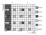
- FIG. 25 is a diagram illustrating a configuration example of a subframe (for example, Non-Patent Document 1 below).
- the horizontal axis represents time
- the vertical axis represents frequency
- an example in which CRS is transmitted using four transmission antennas is shown.
- the base station transmits CRS, data, and the like from each antenna using the scheduled subframe.
- the terminal also holds a subframe as shown in the figure, and receives CRS, data, etc. from the base station at each time and at each frequency.
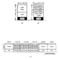
- FIG. 26 is a diagram showing an example of channel resource allocation (for example, Non-Patent Document 5 below).
- one resource block corresponds to the subframe in FIG.
- the base station may transmit CRS, data, and the like in a situation where LTE-compliant terminals and LTE-A-compliant terminals coexist.
- the base station transmits CRS, data, etc. using two types of resource blocks (resource blocks for LTE-compliant terminals and resource blocks for LTE-A-compliant terminals) as shown in FIG. To do.
- 3GPP TS 36.211 3GPP TS 36.222
- 3GPP TS 36.213 3GPP TR 36.913 v8.0.0
- the base station allocates resources for CRS transmission to a maximum of four transmission antennas (see FIG. 25).
- one of the objects of the present invention is to provide a radio communication system, a base station apparatus, and a radio communication method in the radio communication system that can transmit reference signals from five or more transmission antennas.
- Another object of the present invention is to provide a wireless communication system and the like that make effective use of resources.
- the base station device has five or more transmission antennas, a data channel region, and a control channel region.
- M (m is an integer satisfying 1 ⁇ m ⁇ 5), which is a region different from the first region to which each resource of the common reference signal transmitted from the transmitting antennas up to the first is allocated, and data is allocated.
- M (m is an integer satisfying 1 ⁇ m ⁇ 5), which is a region different from the first region to which each resource of the common reference signal transmitted from the transmitting antennas up to the first is allocated, and data is allocated
- Each of the common reference signals transmitted from each of the fifth and subsequent transmission antennas so as to overlap the control channel region to which the assigned data channel region or control signal is assigned and to be different from each other.
- the first scheduling information to which resources are allocated and an area different from the first area, wherein the data in the data channel area Individual areas transmitted from each of the fifth and subsequent transmission antennas so that they are areas that are not allocated or areas where the control signal is not allocated in the control channel area, and overlap with each other and differ in the code area.
- a scheduling information holding unit that holds second scheduling information to which each resource of the reference signal is assigned, and based on the first or second scheduling information, the data, the control signal, the common reference signal, and
- a transmitting unit that transmits the dedicated reference signal, and the terminal device receives the data, the control signal, and the common reference signal or the dedicated reference signal based on the first or second scheduling information.
- a receiving unit configured to transmit the common reference signal using a predetermined code.
- a base station apparatus that performs radio communication with a terminal apparatus has five or more transmission antennas, a data channel area, and a control channel area, and m (m is 1 ⁇ m ⁇ 5).
- An integer satisfying) a region different from the first region to which each resource of the common reference signal transmitted from each of the transmitting antennas up to the main is allocated, and the data channel region or the control signal to which data is allocated is First scheduling information to which each resource of the common reference signal transmitted from each of the fifth and subsequent transmission antennas is allocated so as to overlap with the allocated control channel region and to be different from each other.
- a scheduling information holding unit for holding the received second scheduling information, and transmitting the data, the control signal, the common reference signal, and the individual reference signal based on the first or second scheduling information
- a transmission unit, and the transmission unit transmits the common reference signal using a predetermined code.
- a terminal apparatus that performs radio communication with a base station apparatus having five or more transmission antennas has a data channel region and a control channel region, and m (m is 1 ⁇ m ⁇ 5).
- An integer satisfying) a region different from the first region to which each resource of the common reference signal transmitted from each of the transmitting antennas up to the main is allocated, and the data channel region or the control signal to which data is allocated is First scheduling information to which each resource of the common reference signal transmitted from each of the fifth and subsequent transmission antennas is allocated so as to overlap with the allocated control channel region and to be different from each other. And an area different from the first area, in which the data is not allocated in the data channel area.
- Each resource of the individual reference signal transmitted from each of the fifth and subsequent transmission antennas is an area where the control signal is not allocated in the control channel area, and overlaps each other and is a different area in the code area.
- a scheduling information holding unit that holds the assigned second scheduling information, and receives the data, the control signal, and the common reference signal or the individual reference signal based on the first or second scheduling information.
- a receiving unit, and the receiving unit receives the common reference signal transmitted by a predetermined code.
- the base station device having five or more transmission antennas is the base station device.
- the terminal device Based on the first or second scheduling information held in the scheduling information holding unit, the terminal device transmits the data, the control signal, the individual reference signal, and the common reference signal.
- the data, control signal, and the common reference signal or the dedicated reference signal are received based on the scheduling information, and the first scheduling information includes a data channel region and a control channel region, and m (m Is an integer satisfying 1 ⁇ m ⁇ 5)
- Each of the resources of the common reference signal transmitted from each of the transmitting antennas up to the first is allocated.
- each resource of a common reference signal transmitted from each of the transmission antennas is allocated, and the second scheduling information is an area different from the first area, and the data is allocated in the data channel area.
- the individual reference signals transmitted from each of the fifth and subsequent transmission antennas so that the control signals are not allocated in the non-region or the control channel region, and are different from each other in the code region.
- Each resource is allocated, and in the transmission step, the base station apparatus A common reference signal transmitted by a predetermined code.
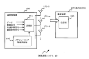
- FIG. 1 is a diagram illustrating a configuration example of a wireless communication system.
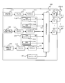
- FIG. 2 is a diagram illustrating a configuration example of a base station.
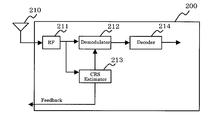
- FIG. 3 is a diagram illustrating a configuration example of the terminal device.
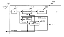
- FIG. 4 is a diagram illustrating a configuration example of another terminal device.
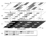
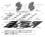
- FIGS. 5A to 5C are diagrams showing examples of subframe configurations, and FIG. 5D is an explanatory diagram.
- FIGS. 6A to 6C are diagrams showing another configuration example of the subframe, and FIG. 6D is an explanatory diagram.
- FIGS. 7A to 7C are diagrams showing another configuration example of the subframe, and FIG. 7D is an explanatory diagram.
- FIGS. 8A to 8C are diagrams showing other examples of the configuration of subframes.
- FIG. 9A to FIG. 9C are diagrams showing other configuration examples of subframes.
- FIGS. 10A to 10C are diagrams showing other examples of the configuration of subframes.
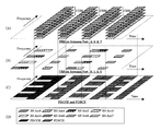
- FIGS. 11A to 11C are diagrams showing another configuration example of the subframe, and FIG. 11D is an explanatory diagram.
- FIGS. 12A to 12C are diagrams showing another configuration example of the subframe, and FIG. 12D is an explanatory diagram.
- FIGS. 13A to 13C are diagrams showing another example of the configuration of the subframe, and FIG. 13D is an explanatory diagram.
- FIGS. 14A to 14C are diagrams showing another example of the configuration of subframes, and FIG. 14D is an explanatory diagram.
- FIGS. 15A to 15C are diagrams showing another configuration example of the subframe, and FIG. 15D is an explanatory diagram.
- FIGS. 16A to 16C are diagrams showing another example of the configuration of the subframe, and FIG. 16D is an explanatory diagram.
- FIGS. 17A to 17C are diagrams showing another configuration example of the subframe, and FIG. 17D is an explanatory diagram.
- FIGS. 18A to 18C are diagrams showing another configuration example of the subframe, and FIG. 18D is an explanatory diagram.
- FIGS. 19A to 19C are diagrams showing another configuration example of the subframe, and FIG. 19D is an explanatory diagram.
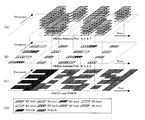
- FIGS. 20A and 20B are diagrams illustrating another example of the configuration of the subframe, and FIG.
- FIG. 20C is an explanatory diagram.
- FIGS. 21A to 21D show examples of code strings, and FIGS. 21E to 11H show other examples of code strings.
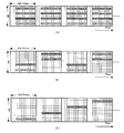
- 22A to 22C are diagrams showing examples of transmission power.
- FIG. 23 is a flowchart showing an operation example of the base station apparatus.
- FIG. 24A is a flowchart showing an operation example of a terminal, and
- FIG. 24B is a flowchart showing an operation example of another terminal.
- FIG. 25 is a diagram illustrating another configuration example of the subframe.
- FIG. 26 is a diagram illustrating an example of resource allocation.
- FIG. 1 is a diagram illustrating a configuration example of a wireless communication system 10.
- the base station apparatus 100 includes five or more transmission antennas 170, a data channel area, and a control channel area. And m (m is an integer satisfying 1 ⁇ m ⁇ 5), and is a region different from the first region to which each resource of the common reference signal transmitted from each transmitting antenna 170 is allocated, Common data transmitted from each of the fifth and subsequent transmitting antennas 170 so as to overlap the data channel area to which data is assigned or the control channel area to which a control signal is assigned and to be different from each other.
- the first scheduling information to which each resource of the reference signal is allocated is an area different from the first area, and Each of the fifth and subsequent transmissions is an area where the data is not assigned in the data channel area or an area where the control signal is not assigned in the control channel area, and overlaps each other and becomes a different area in the code area.
- a scheduling information holding unit 180 that holds second scheduling information to which each resource of the dedicated reference signal transmitted from the antenna 170 is assigned; and the data, the control based on the first or second scheduling information
- a transmission unit 181 that transmits a signal, the common reference signal, and the dedicated reference signal, and the terminal device 200 (300) determines the data and control signal based on the first or second scheduling information. And receiving the common reference signal or the individual reference signal A receiving unit 230 that the transmission unit 181 transmits the common reference signal by a predetermined code.
- the transmission unit 181 reads the first scheduling information from the scheduling information holding unit 180 and transmits data, a control signal, and a common reference signal transmitted from the transmission antenna 170 based on the first scheduling information.
- the transmission unit 181 reads the second scheduling information from the scheduling information holding unit 180, and transmits the data, the control signal, and the transmission antennas 170-0 to 170-3 based on the second scheduling information.
- the common reference signal and the individual reference signal transmitted from the transmission antennas 170-4, ... are transmitted.
- the receiving unit of the terminal device 200 receives the data, the control signal, and the common reference signal transmitted from the transmission antenna 170 based on the first scheduling information, and the data, The control signal, the common reference signal transmitted from the transmission antennas 170-0 to 170-3, and the individual reference signal transmitted from the transmission antennas 170-4,.
- the common reference signal transmitted from each of the transmission antennas subsequent to the transmission antenna 170-4 is transmitted using resources overlapping with the data or control signal, five or more transmission antennas 170-4 are used. ,... Can be transmitted from the common reference signal, and further, the resources are transmitted using overlapping resources, so that the resources can be effectively used.
- the individual reference signals transmitted from the transmission antennas after the transmission antenna 170-4 are transmitted using resources that do not overlap with data, etc., and the individual reference signals are the resources that overlap each other. Sent using. Therefore, individual reference signals can be transmitted from five or more transmission antennas 170-4,. In addition, since each individual reference signal is transmitted by resources overlapping each other and no other resources are used, the resources can be effectively used.
- FIG. 2 is a diagram showing a configuration example of a base station apparatus (hereinafter referred to as a base station) 100 in the wireless communication system 10, and FIGS.
- the base station 100 includes a first encoder 111, a first modulator 112, and a first RS (reference).
- signal reference signal
- signal second encoding unit (Encoder) 121, second modulation unit 122, second RS generation unit 124, control signal generation unit 130, third encoding unit 131, 3 modulation unit 132, scheduler 140, multiplexing unit 150, RF unit (Radio Frequency) 160-0 to 160-7 and transmitting antennas 170-0 to 170-7.
- the base station 100 transmits data using a plurality of transmission antennas 170-0 to 170-7 (MIMO (Multi-Input Multi-Output)).
- MIMO Multi-Input Multi-Output
- the first encoding unit 111 receives data 110 that can be received by the LTE-compliant terminal 200 and outputs encoded data.
- the first modulation unit 112 modulates the data output from the first encoding unit 111 and outputs the result.
- the first RS generation unit 114 includes a first CRS generation unit 1141 and a second CRS generation unit 1142.
- the first CRS generation unit 1141 is configured to transmit a CRS (common) transmitted from the transmission antennas 170-0 to 170-3.
- reference signal common reference signal
- the second CRS generator 1142 generates CRS transmitted from the transmission antennas 170-4 to 170-7.
- the second encoding unit 121 receives data 120 that can be received by the LTE-A compliant terminal 300, and outputs encoded data.
- the second modulation unit 122 modulates the data output from the second encoding unit 121 and outputs the result.
- the second RS generation unit 124 includes a third CRS generation unit 1241 and a DRS generation unit 1242.
- the third CRS generator 1241 generates CRS transmitted from the transmission antennas 170-0 to 170-3.
- the DRS generator 1242 transmits a DRS (dedicated signal) transmitted from the transmission antennas 170-4 to 170-7.
- reference signal individual reference signal).
- the control signal generator 130 generates a control signal.
- the third encoding unit 131 encodes the control signal output from the control signal generation unit 130.
- the third modulator 132 modulates the encoded control signal output from the third encoder 131.
- the scheduler 140 holds scheduling information (subframe or radio frame) and outputs it to the multiplexing unit 150.
- the scheduling information includes first scheduling information for the LTE compliant terminal 200 and second scheduling information for the LTE-A compliant terminal 300. Details of the scheduling information will be described later.
- Multiplexer 150 performs first radio frame scheduling from scheduler 140 on the data from first modulator 112, the CRS from first RS generator 114, and the control signal from control signal generator 130. Mapping is performed based on the information. Further, the multiplexing unit 150 receives the second signal from the scheduler 140 for the data from the second modulation unit 122, the CRS and DRS from the second RS generation unit 124, and the control signal from the control signal generation unit 130. Mapping is performed based on the scheduling information. The multiplexing unit 150 multiplexes and outputs the two mapped data.
- the RF units 160-0 to 160-7 each convert the data from the multiplexing unit 150 into a radio signal and output it.
- the transmission antennas 170-0 to 170-7 transmit radio signals from the RF units 160-0 to 160-7 to the terminals 200 and 300.
- FIG. 3 is a diagram illustrating a configuration example of a terminal 200 compliant with LTE
- FIG. 4 is a diagram illustrating a configuration example of a terminal 300 compliant with LTE-A.
- the terminal 200 includes a reception antenna 210, an RF unit 211, a demodulator 212, a CRS estimator 213, and a decoder 214.
- the receiving antenna 210 receives a radio signal including data and CRS transmitted from the base station 100.
- the RF unit 211 converts the radio signal received by the receiving antenna 210 into data before radio signal conversion in the base station 100 or the like.
- the demodulation unit 212 demodulates data with respect to the output from the RF unit 211.
- the decoding unit 214 decodes the demodulated data.
- the decoded data is subjected to voice processing and the like in various processing units.
- the CRS estimation unit 213 estimates the CRS for the signal output from the RF unit 211 based on the scheduling information.
- the scheduling information is the same information as the first scheduling information held by the base station 100, and is held by the CRS estimation unit 213, for example.
- the CRS estimation unit 213 estimates the CRS transmitted from the transmission antennas 170-0 to 170-3 of the base station 100.
- the CRS estimation unit 213 performs processing such as channel estimation and coherent detection based on the CRS.
- the CRS estimator 213 receives the measurement result and the like as feedback information (for example, CQI (Channel Quality Indicator)) is transmitted to the base station 100. Further, the CRS estimation unit 213 outputs the detection result of the coherent detection to the demodulation unit 212.
- the demodulator 212 demodulates data based on the detection result.
- the LTE-A compliant terminal 300 includes a reception antenna 310, an RF unit 311, a demodulation unit (Demodulator) 312, an RS estimation unit (RS Estimator) 313, and a decoder (decoder) 314.
- the receiving antenna 310 receives a radio signal transmitted from the base station 100.
- the RF unit 311 converts the radio signal received by the reception antenna 310 into data before radio signal conversion in the base station 100.
- the demodulation unit 312 demodulates data with respect to the output from the RF unit 311.
- the decoding unit 314 decodes the demodulated data.
- the decoded data is subjected to voice processing and the like in various processing units.
- the RS estimation unit 313 includes a DRS estimation unit 3130 and a CRS estimation unit 3131.
- the DRS estimation unit 3130 estimates the DRS transmitted from the transmission antennas 170-4 to 170-7 of the base station 100 with respect to the output of the RF unit 311.
- the DRS estimation unit 3130 estimates DRS based on the scheduling information.
- the scheduling information is the same as the second scheduling information held by the base station 100. For example, the DRS estimation unit 3130 holds such scheduling information.
- the DRS is a reference signal assigned to each terminal 300.
- the terminal 300 can perform channel estimation, coherent detection, and the like using this DRS, thereby performing channel estimation and the like with higher accuracy than the CRS. it can.
- the DRS estimation unit 3130 transmits the quality measurement result to the base station 100 as CQI, for example. Further, DRS estimation section 3130 outputs the coherent detection result to demodulation section 312. The demodulator 312 demodulates the data based on the detection result.
- the CRS estimation unit 3131 estimates the CRS transmitted from the transmission antennas 170-0 to 170-3 of the base station 100 with respect to the output of the RF unit 311.
- the CRS estimation unit 3131 may estimate the CRS transmitted from the transmission antennas 170-4 to 170-7.
- the estimation of CRS is performed based on scheduling information (for example, first and second scheduling information or second scheduling information). For example, the CRS estimation unit 3131 holds such scheduling information.
- the CRS estimation unit 3131 performs processing such as quality measurement and coherent detection based on the estimated CRS, transmits the measurement result to the base station 100 as, for example, CQI, and outputs the detection result to the demodulation unit 312.
- the demodulator 312 performs demodulation using the detection result.
- the LTE-compliant terminal 200 estimates the CRS transmitted from the transmission antennas 170-0 to 170-3 among the CRS, and the LTE-compliant terminal 300 estimates the CRS transmitted from the transmission antennas 170-0 to 170-7. To do. This may be estimated based on the scheduling information (first scheduling information and second scheduling information) described above.
- the terminals 200 and 300 may read out the control signal from the received signal and then determine whether to read out the data.
- the CRS estimation unit 213 of the terminal 200 may demodulate the control signal, determine whether to read data based on the control signal, and notify the demodulation unit 212 of the result when reading.
- the demodulator 212 demodulates data based on the notification.
- the DRS estimator 3130 or CRS estimator 3131 of the terminal 300 may determine whether to read data by demodulating the control signal or the like, and may notify the demodulator 312 of the result when reading. *
- scheduling information held by the scheduler 140 of the base station 100 There are two types of scheduling information: first scheduling information (for example, for LTE-compliant terminal 200) and second scheduling information (for example, for LTE-A-compliant terminal 300).
- first scheduling information for example, for LTE-compliant terminal 200
- second scheduling information for example, for LTE-A-compliant terminal 300.
- the first scheduling information includes CRS resource elements transmitted from the transmission antennas 170-4 to 170-7, and the second scheduling information is transmitted from the transmission antennas 170-4 to 170-7.
- a DRS resource element is included.
- Terminal 200 can receive CRS or the like based on the first scheduling information, and terminal 300 can receive DRS or the like based on the second scheduling information.
- FIGS. 5A to 5C are diagrams illustrating an example of the configuration of subframes.
- the scheduler 140 of the base station 100, the CRS estimation unit 213 of the terminal 200, the RS estimation unit 313 of the terminal 300, etc. hold the subframes shown in the figure as scheduling information.
- 5A to 5C are divided into three layers for ease of explanation, but in actuality, the sum of these layers is held as a subframe.
- 5A to 5C the horizontal axis indicates the time axis direction
- the vertical axis indicates the frequency axis direction
- each block indicates a resource element.
- FIG. 5D is a diagram for explaining the resource elements shown in FIG.
- a control signal (PDCCH) and data (PDSCH) are allocated to resource elements of CRS transmitted from transmission antennas 170-0 to 170-3. Allocated to an area that does not overlap with the resource element.
- the CRS resource elements transmitted from the transmission antennas 170-4 to 170-7 are areas that do not overlap with the CRS resource elements transmitted from the transmission antennas 170-0 to 170-3, and data is allocated to them. Assigned to an area that overlaps a resource element that is assigned (also referred to as “super-position manager”).
- the resource elements (total 12) of each CRS transmitted from each of the transmission antennas 170-4 to 170-7 are the resource element area of the data, and the same timing ( This is an example in which a plurality of frequency bands (a plurality of frequency domains) of one subframe are allocated in the same time domain).
- the CRS can be transmitted from the transmission antennas 170-4 to 170-7 of the base station 100 by assigning the CRS resource elements transmitted from the transmission antennas 170-4 to 170-7. Further, the terminals 200 and 300 can receive the CRS at a predetermined timing and frequency based on the scheduling information.
- the CRS transmitted from the transmitting antennas 170-4 to 170-7 is set to a predetermined code.
- codes are generated by the second and third CRS generators 1142 and 1241 of the base station 100. Since the CRS is transmitted using a predetermined code, the terminals 200 and 300 can perform demodulation or the like of the CRS by distinguishing from data in an area overlapping with the CRS.
- the predetermined code will be described later.
- the base station 100 transmits data in an area overlapping with the CRS with higher transmission power than the CRS. Based on the data transmitted with high transmission power, the terminals 200 and 300 can demodulate the data separately from the CRS. The transmission power will be described later.
- the said CRS has transmission power smaller than data, since it is transmitted using the some resource element, the said CRS can be read by collecting these.
- FIG. 6A to FIG. 12D are diagrams showing modifications.
- 6 (A) to 6 (C) are data regions of one subframe, and each CRS transmitted from each of the transmission antennas 170-4 to 170-7 in the same frequency band in one subframe.
- This is an assigned example.
- base station 100 performs coding in the frequency direction at a certain timing
- CRS from the same transmission antennas 170-4 to 170-7 is dispersed by assigning CRS as shown in FIG. For example, it is advantageous when the CRS is decoded by the terminals 200 and 300.
- FIG. 7A to FIG. 7D show resource elements that are different from each other in the frequency domain and the time domain in the data domain, and each transmitting antenna 170-4 does not overlap each other in the frequency domain and the time domain.
- each CRS transmitted from ⁇ 170-7 is assigned.
- each CRS is assigned to a distributed area, so that the error rate can be lowered as compared with the case of FIG.
- FIGS. 8A to 8C are diagrams showing examples of pattern configurations of the CRSs transmitted from the transmission antennas 170-4 to 170-7.
- FIG. 8A corresponds to the example of FIG. 5A, and is an example in which all CRSs of the transmission antennas 170-4 to 170-7 are assigned to each subframe.
- the example of FIG. 8A shows an example of a subframe with the highest CRS density.
- FIG. 8B shows an example in which the CRS of the transmission antennas 170-4 and 170-5 is assigned to the first subframe, and the CRS of the transmission antennas 170-6 and 170-7 is assigned to the second subframe, and this is repeated. is there.
- the density of the CRSs can be reduced. Since the load of CRS transmission is reduced in each subframe and the CRS resource area is smaller than in the example of FIG. 8A, the terminals 200 and 300 can receive data allocated to the data area at a low error rate. .
- the first subframe and the second subframe are alternately switched.
- the scheduler 140 of the base station 100 alternates these subframes at a predetermined timing. And output to the multiplexing unit 150.
- the terminals 200 and 300 may receive CRS and the like by alternately switching the subframes held in the CRS estimation unit 213, the DRS estimation unit 3130, and the CRS estimation unit 3131 at a predetermined timing, for example.
- FIG. 8C shows an example in which each CRS transmitted from each of the transmission antennas 170-4 to 170-7 is assigned to each subframe one by one.
- four subframes are sequentially repeated.
- the scheduler 140 of the base station 100 holds four subframes, sequentially switches them at a predetermined timing, and outputs them to the multiplexing unit 150.
- the terminals 200 and 300 may also sequentially switch the subframes held by the CRS estimation unit 213 and the like.
- the switching unit that performs the switching is the multiplexing unit 150 or the scheduler 140, the CRS estimation unit 213, the DRS estimation unit 3130, and the CRS estimation unit 3131.
- 9A to 9C are examples corresponding to FIG. 6A and the like.
- 9A is an example in which each CRS is assigned to each subframe
- FIG. 9B is an example in which two CRSs are assigned to each subframe alternately
- FIG. 9C is an example in which each CRS is assigned to each subframe.
- Each example assigned is shown below.
- the base station 100 reduces the load of CRS transmission, and the terminals 200 and 300 can receive data with a low error rate.
- FIG. 10A to 10C are examples corresponding to FIG. 7A and the like.
- FIG. 10A shows an example in which each CRS is assigned so as not to overlap each other in the frequency domain and the time domain and has the highest density.
- FIG. 5B shows an example in which two CRSs are alternately assigned to each subframe, and
- FIG. 4C shows an example in which each CRS is assigned to each subframe. Even in these cases, the base station 100 can reduce the load of CRS transmission, and the terminals 200 and 300 can receive data at a low error rate.
- the second scheduling information includes DRS resources.
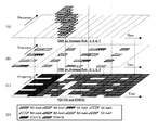
- FIGS. 11A to 11C are diagrams showing examples of second scheduling information. Although FIGS. (A) to (C) are divided into three layers for ease of explanation, the sum of these layers is actually held in the base station 100 and the terminal 300 as subframes.
- FIG. 4D is a diagram for explaining the resource elements shown in FIG.
- DRS transmitted from each of the transmission antennas 170-4 to 170-7 is an area to which no data is allocated in the data area (PDSCH), and each of the transmission antennas 170-0 to 170 is transmitted.
- the resource elements of each DRS transmitted from each of the transmission antennas 170-4 to 170-7 are allocated so as to overlap with the areas that do not overlap with the resource elements of each CRS transmitted from (-3) ("CDM ( code division multiplexing).
- each DRS transmitted from each of the transmission antennas 170-4 to 170-7 is assigned to a different area in the code area (upward in FIG. 5A).
- the terminal 300 can receive the DRS with a small error rate, for example, and the terminal 300 can perform highly accurate quality measurement using the individually assigned DRS. Coherent detection for demodulation can be performed.
- each DRS transmitted from each of the transmission antennas 170-4 to 170-7 are assigned redundantly, the resource elements are compared with the case where each DRS is assigned to a different area. It can be used effectively.
- FIGS. 12A to 12C are data regions in a subframe, and all DRSs transmitted from the transmission antennas 170-4 to 170-7 are assigned to the same frequency in one subframe. This is an example. Similar to the example of FIG. 6A, when encoding is performed in the frequency axis direction, DRS is dispersed, which is advantageous when terminal 300 decodes DRS.
- FIGS. 13A to 13D show examples in which DRSs are resource elements different from each other in the frequency domain and the time domain in the data domain, and are assigned so that they do not overlap each other in the frequency domain and the time domain. It is. As in FIG. 7A and the like, since the DRS is assigned to the dispersed area, the error rate can be lowered as compared with the case of FIG. 11A and the like.
- FIGS. 14A to 19D are diagrams showing configuration examples of DRS patterns. Instead of assigning all DRSs to each subframe, two DRSs can be assigned to each subframe as shown in FIG. 14A, and one can be assigned to each subframe as shown in FIG. Since the DRS density in one subframe is reduced, the DRS transmission load of the base station 100 is reduced. In addition, since resource elements to which data is allocated in the data area increase as compared with the case of FIG. 11A, the base station 100 can transmit more data by that amount, and for example, the terminal 300 can improve throughput. . Note that the examples of FIGS. 14A and 15A are examples in which DRSs are allocated over the entire frequency band of one subframe at the same timing.
- FIGS. 16A to 16D show an example in which two overlapping DRSs are assigned to one subframe, and the DRS density compared to the case of FIG. 12A in which four DRSs are assigned. Lower.
- FIGS. 17A to 17D are examples in which one overlapping DRS is assigned to one subframe, and the DRS density is further reduced.
- 18A to 19D are also examples in which the DRS density is lowered.
- the switching unit that performs the switching is the multiplexing unit 150 or the scheduler 140, the CRS estimation unit 213, the DRS estimation unit 3130, and the CRS estimation unit 3131.
- the base station 100 can reduce the DRS transmission load, and the number of resource elements to which data is allocated increases, so that the terminal 300 can improve the throughput.
- FIGS. 20A to 20C are diagrams showing such an example.
- FIG. 3A shows an example of CRS resource allocation transmitted from the transmission antennas 170-4 to 170-7.
- FIG. 5B is a diagram showing an example in which four overlapping DRSs are assigned to the same area as the resource element to which the CRS is assigned.
- the DRS (RS Ant4) transmitted from the transmission antenna 170-4 is assigned to the same area as the CRS transmitted from the same antenna.
- the terminal 300 can perform channel quality measurement, for example, by using CRS transmitted from the same antenna as the DRS transmitted from the transmission antenna 170-4 in the DRS, and use CQI feedback information or the like.
- DRS Downlink Reference Signal
- FIGS. 21A to 21D are diagrams showing examples of CRS or DRS code examples transmitted from the transmission antennas 170-4 to 170-7, respectively.
- 12 resource elements are allocated to each CRS
- the code sequence of CRS transmitted from the transmission antenna 170-4 is (+1, +1, +1, +1, +1, +1).
- +1, +1, +1, +1, +1, +1, +1) (Sequence-0).
- a code string is any other code string (Sequence-1 to Sequence-3)
- each code is multiplied by each other, and even if the multiplied ones are added, all the added values are “0”. There is a correlation with each other.
- Such a code sequence is called “Walsh code”.
- terminals 200 and 300 can suppress interference from data in overlapping resource element regions and can easily decode CRS. Further, when a code sequence related to DRS is used, terminal 300 can easily decode DRS.
- the terminals 200 and 300 estimate CRS and DRS of such code sequences, and perform channel estimation and the like using the CRS and DRS, for example, the CRS estimation unit 213, the DRS estimation unit 3130, and the CRS estimation unit 3131.
- the CRS estimator 213 and the like can perform channel estimation using, for example, four code sequences out of all twelve code sequences and output three estimation results.
- channel estimation is performed at once using a total of 12 code sequences, the channel is averaged as a whole, but by using three estimation results, for example, a local change can be detected.
- FIG. 21 (E) to FIG. 21 (H) are diagrams showing examples of other code sequences used for CRS and DRS.
- This code sequence is called “Barker Sequence”, and each code sequence (Sequence-0 to Sequence-3) has a correlation with each other like “Walsh code”.
- the terminals 200 and 300 can suppress interference from data and can easily decode CRS and DRS.
- the CRS transmitted from the transmitting antennas 170-4 to 170-7 is assigned to resource elements that overlap with data in the data area (PDSCH) in which data is transmitted (FIGS. 5A to 10D). ).
- the magnitude of transmission power such as data transmitted from each of the transmission antennas 170-4 to 170-7 is determined in advance. Therefore, when transmitting the CRS, the base station 100 sets the transmission power of the data to be larger than the transmission power of the CRS so that the sum of both becomes a predetermined transmission power.
- the base station 100 can transmit data and CRS simultaneously and at the same frequency with each transmission power.
- FIGS. 22A and 22B are diagrams illustrating examples of power control.
- FIG. 22A illustrates an example in which data and CRS are transmitted with each transmission power after allowing for noise.
- FIG. The example of FIG. 5B is an example of DRS transmission.
- DRS since each DRS is assigned to the same resource element, for example, “Dual-Type DRS” determines each transmission power so as to have a larger transmission power than “Sole-Type DRS”.
- the upper limit of the power transmitted from each of the transmission antennas 170-4 to 170-7 may be set as a whole.
- each transmission power may be determined in consideration of noise.
- “Dual-Type DRS” may have the same transmission power as “Sole-Type DRS” or a different transmission power. “Dual-Type DRS” may be the same as the transmission power of CRS as shown in FIGS. 22 (A) and 22 (B).
- the second CRS generation unit 1142 of the base station 100 outputs the above-described CRS or data output from the first CRS generation unit 1141 or the first modulation unit 112 by applying a weight.
- Power control can be performed.
- a weight may be applied to each DRS output from the DRS generator 1242.
- FIG. 22 (C) is a diagram illustrating an example of transmission power of resource elements including CRS and resource elements including DRS transmitted from the transmission antennas 170-4 to 170-7 in each subframe.
- a part of the duplicated DRS can be used as the CRS.
- the transmission power of the “Dual-Type DRS” needs to be the same as the transmission power of the CRS transmitted from the transmission antennas 170-4 to 170-7.
- the DRS estimation unit 3130 of the terminal 300 can easily estimate the DRS to be used as the “Dual-Type DRS” from the plurality of DRSs by holding the transmission power information of the CRS (or “Dual-Type DRS”). .
- FIG. 23 shows an example of the operation of the base station 100
- FIG. 24A shows an operation of the terminal 200
- FIG. 24A shows an operation of the terminal 200
- the control signal generator 130 When the base station 100 starts processing (S10), the control signal generator 130 generates a control signal (S20). Next, the third encoding unit 131 encodes the control signal (S21), and the third encoding unit 131 modulates the encoded control signal and outputs the modulated control signal to the multiplexing unit 150 (S22).
- the data is output to the first and second encoding units 111 and 121, respectively (S30), and the first and second encoding units 111 and 121 encode the data (S31).
- the first and second modulators 112 and 122 modulate the encoded data and output the data to the multiplexer 150 (S32).
- the first and third CRS generators 1141 generate CRSs transmitted from the transmission antennas 170-0 to 170-3, and output them to the multiplexer 150 (S40).
- the second CRS generator 1142 generates CRS transmitted from the transmission antennas 170-4 to 170-7, and outputs it to the multiplexer 150 (S50). At this time, second CRS generation section 1142 outputs a CRS by applying a weight so that the transmission power is low for the data in the overlapping area.
- the DRS generator 1242 generates DRS transmitted from the transmission antennas 170-4 to 170-7, and outputs it to the multiplexer 150 (S60). For example, the DRS generation unit 1242 outputs each DRS with a weight so that the transmission power of other DRSs is reduced with respect to the DRS of “Dual-Type DRS”.
- the multiplexing unit 150 assigns the CRS from the second CRS generation unit 1142 to the LTE compliant terminal 200 and the DRS from the DRS generation unit 1242 to the LTE-A compliant terminal 300. (S51).
- the multiplexing unit 150 multiplexes the data, the CRS, and the DRS after the processing of S22, S32, and S51 is completed, and first and second scheduling information from the scheduler 140 (for example, FIG. 5A). Based on (C) of FIG. 11 and (A) to (C) of FIG. 11), data and the like are mapped to each frequency domain and each time domain (S11).
- the RF units 160-0 to 160-7 convert the output from the multiplexing unit 150 into a radio signal (S12), and each of the transmission antennas 170-0 to 170-7 uses the radio signal as a transmission signal for each terminal 200. , 300 is transmitted wirelessly. Then, a series of processing ends (S13).
- the RF unit 211 of the terminal 200 converts the transmission signal received by the antenna 210 into a signal before RF conversion in the base station 100 (S71).
- the CRS estimation unit 213 estimates the CRS with respect to the output from the RF unit 211 (S72).
- the CRS estimation unit 213 may estimate the CRS transmitted from all the transmission antennas 170-0 to 170-7 of the base station 100, or may estimate the CRS transmitted from the transmission antennas 170-0 to 170-3. May be.
- the CRS estimation unit 213 estimates the CRS based on the first scheduling information held by itself.
- the CRS estimator 213 performs coherent detection based on the estimated CRS and outputs the detection result to the demodulator 212. Further, the CRS estimator 213 performs channel estimation based on the estimated CRS, and the base station 100 uses the estimation result as CQI, for example. (S73 to S74).
- the demodulator 212 demodulates data based on the detection result from the CRS estimator 213 (S75), and the decoder 214 decodes the demodulated data (S76). Then, a series of processing ends (S77).
- the RF unit 311 of the terminal 300 converts the received signal received by the antenna 310 into a signal before RF conversion in the base station 100 (S81).
- the DRS estimation unit 3130 estimates the DRS transmitted from the transmission antennas 170-4 to 170-7 of the base station 100 (S90).
- the DRS estimation unit 3130 estimates the DRS based on the second scheduling information held by itself, for example. Further, the DRS estimation unit 3130 performs channel estimation, coherent detection, and the like based on the estimated DRS, and feeds back the channel estimation result to the base station 100 as CQI (S101 to S102).
- the DRS estimation unit 3130 outputs the detection result of the coherent detection to the demodulation unit 312.
- the CRS estimation unit 3131 estimates the CRS transmitted from the transmission antennas 170-0 to 170-3 of the base station 100 (S100). For example, the CRS estimation unit 3131 estimates the CRS based on the second scheduling information held by itself. The CRS estimation unit 3131 performs channel estimation based on the CRS, and feeds back the estimation result to the base station 100 as CQI (S101 to S102). Further, the CRS estimation unit 3131 performs coherent detection based on the CRS and outputs the detection result to the demodulation unit 312.
- the demodulator 312 demodulates the data based on the estimation result from the DRS estimator 3130 or the CRS estimator 3131 (S82).
- the decoding unit 314 decodes the demodulated data (S83). Then, a series of processing ends (S84).
- precoding for mapping a data string to each of the transmission antennas 170-0 to 170-7 may be performed.
- This embodiment can be implemented even when the base station 100 performs precoding.
- the base station 100 and the terminal 200 and 300 hold, for example, determinants for performing precoding, and each CRS can be estimated by performing processing related to precoding using the same determinant.
- Precoding processing is performed by, for example, multiplexing section 150 of base station 100, CRS estimation section 213 or demodulation section 212 of terminal 200, RS estimation section 313 or demodulation section 312 of terminal 300, and the like.
- Terminals 200 and 300 may transmit feedback information (for example, CQI), and for example, multiplexing section 150 of base station 100 may perform precoding processing based on the feedback information.
- the base station 100 has been described as having eight transmission antennas.
- the number of transmitting antennas may be 5 or more.
- the CRS transmitted from the transmission antenna 170-4 may be assigned to any one of the four CRS sequences shown in FIG.
- any one of duplicate DRS sequences shown in FIG. 11A may be used.
- the DRS is assigned to the same area as any one area shown in FIG. 5A so that the DRS plays a role as the CRS.
- the number of transmission antennas is nine or more, resource elements are separately allocated to CRSs transmitted from the ninth and tenth transmission antennas.
- DRS should just change the number of each DRS which overlapped according to the number of transmitting antennas.
- the CRS resource elements transmitted from the transmitting antennas 170-4 to 170-7 are allocated over the entire frequency band of each subframe, for example (see FIG. 5A).
- the number of resource elements of each CRS transmitted from each of the transmission antennas 170-4 to 170-7 may be one instead of twelve.
- the CRS estimation unit 213 and the like can easily estimate CRSs by collecting CRSs having low transmission power.
- data can be assigned to many resource elements, and effective utilization of resources can be achieved.
- the number of resource elements may be one instead of plural such as twelve. Similarly, effective utilization of resources can be achieved.
- each CRS transmitted from the transmission antennas 170-4 to 170-7 is assigned a resource on the data channel region (PDSCH) of the subframe (for example, FIG. 5A to FIG. 5).
- PDSCH data channel region
- the CRS may be assigned to the control channel region (PDCCH).
- each DRS transmitted from the transmission antennas 170-4 to 170-7 may also be assigned to the control channel region.
- the scheduling information has been described as being held in the base station 100 and the terminals 200 and 300 in advance.
- the base station 100 or the like includes subframes shown in FIGS. 5A to 5C, subframes shown in FIGS. 6A to 6C, and FIGS.
- the subframe shown in (C) may be held, and switching may be performed based on, for example, feedback information (for example, CQI) from the terminals 200 and 300.
- feedback information for example, CQI
- DRS DRS.
- it can be easily implemented by assigning an identification code to each subframe in advance and including it in the feedback information from the terminals 200 and 300.
- the scheduling information of the terminals 200 and 300 has been described as being stored in the CRS estimation unit 213 and the like.
- a memory may be separately provided and stored.
Landscapes
- Engineering & Computer Science (AREA)
- Signal Processing (AREA)
- Computer Networks & Wireless Communication (AREA)
- Mobile Radio Communication Systems (AREA)
- Radio Transmission System (AREA)
Abstract
Description
evolution)システムでは、共通参照信号(common reference signal、以下CRS)を用いてダウンリンク方向のチャネル推定、コヒーレント検出、セルサーチ等が行われている(例えば、以下の非特許文献1~3)。また、LTEシステムでは、複数の送信アンテナを用いてデータ等を送信することもでき(MIMO(Multi-Input
Multi-Output)と呼ばれる)、最大4本の送信アンテナを使用して送信している。
3GPP TS 36.211 3GPP TS 36.222 3GPP TS 36.213 3GPP TR 36.913 v8.0.0 3GPP TSG RAN1 #55, R1-084251
111:第1の符号化部 112:第1の変調部
114:第1のRS生成部 1141:第1のCRS生成部
1142:第2のCRS生成部 121:第2の符号化部
122:第2の変調部 124:第2のRS生成部
130:制御信号生成部 131:第3の符号化部
132:第3の変調部 140:スケジューラ
150:多重化部 160‐0~160‐7:RF部
170‐0~170‐7:送信アンテナ 200:端末装置
210:受信アンテナ 211:RF部
212:復調部 213:CRS推定部
214:復号化部 300:端末装置
310:受信アンテナ 311:RF部
312:復調部 313:RS推定部
3130:DRS推定部 3131:CRS推定部
第1の実施例について説明する。図1は無線通信システム10の構成例を示す図である。
図2は無線通信システム10における基地局装置(以下、基地局)100、図3及び図4は端末装置200,300の構成例を示す図である。
signal:参照信号)生成部114、第2の符号化部(Encoder)121、第2の変調部122、第2のRS生成部124、制御信号生成部130、第3の符号化部131、第3の変調部132、スケジューラ140、多重化部150、RF部(Radio
Frequency)160‐0~160‐7、送信アンテナ170‐0~170‐7とを備える。基地局100は、複数の送信アンテナ170‐0~170‐7を用いてデータ等を送信する(MIMO(Multi-Input
Multi-Output))。
reference signal:共通参照信号)を生成する。
reference signal:個別参照信号)を生成する。
Quality Indicator))として基地局100に送信する。また、CRS推定部213はコヒーレント検出の検出結果を復調部212に出力する。復調部212は検出結果に基づいてデータを復調する。
division multiplexing) manner」とも言う)。さらに、各送信アンテナ170‐4~170‐7から送信される各DRSはコード領域(同図(A)中、上方向)において互いに異なる領域に割り当てられる。
次にその他の実施例について説明する。
Claims (21)
- 基地局装置と端末装置との間で無線通信を行う無線通信システムにおいて、
前記基地局装置は、
5本以上の送信アンテナと、
データチャネル領域と制御チャネル領域とを有し、m(mは1≦m<5を満たす整数)本目までの各前記送信アンテナから送信される共通参照信号の各リソースが割り当てられた第1の領域とは異なる領域であって、データが割り当てられた前記データチャネル領域または制御信号が割り当てられた前記制御チャネル領域と重複し、かつ互いに異なる領域となるようにするように、5本目以降の各前記送信アンテナから送信される共通参照信号の各リソースが割り当てられた第1のスケジューリング情報と、前記第1の領域とは異なる領域であって、前記データチャネル領域において前記データが割り当てられていない領域または前記制御チャネル領域において前記制御信号が割り当てられていない領域で、かつ互いに重複し、コード領域において異なる領域となるように、5本目以降の各前記送信アンテナから送信される個別参照信号の各リソースが割り当てられた第2のスケジューリング情報とを保持するスケジューリング情報保持部と、
前記第1または第2のスケジューリング情報に基づいて、前記データ、前記制御信号、前記共通参照信号、及び前記個別参照信号を送信する送信部とを備え、
前記端末装置は、前記第1または前記第2のスケジューリング情報に基づいて、前記データ、制御信号、及び前記共通参照信号または前記個別参照信号を受信する受信部を備え、
前記送信部は前記共通参照信号を所定のコードにより送信することを特徴とする無線通信システム。 - 前記送信部は、前記データまたは前記制御信号よりも大きい送信パワーで前記共通参照信号を送信することを特徴とする請求項1記載の無線通信システム。
- 前記第1のスケジューリング情報において、n(nは5以上の整数)本目の前記送信アンテナから送信される前記共通参照信号のリソースは同一の時間領域でかつ複数の周波数領域にわたり割り当てられていることを特徴とする請求項1記載の無線通信システム。
- 前記第1のスケジューリング情報において、n(nは5以上の整数)本目の前記送信アンテナから送信される前記共通参照信号のリソースは同一の周波数領域でかつ複数の時間領域にわたり割り当てられていることを特徴とする請求項1記載の無線通信システム。
- 前記第1のスケジューリング情報において、n(nは5以上の整数)本目の前記送信アンテナから送信される前記共通参照信号のリソースは互いに異なる周波数領域でかつ互いに異なる時間領域に割り当ててられていることを特徴とする請求項1記載の無線通信システム。
- 前記第1のスケジューリング情報において、前記5本目以降の各送信アンテナから送信される共通参照信号の各リソースのうち、少なくとも一つの前記リソースが割り当てられることを特徴とする請求項1記載の無線通信システム。
- 前記スケジューリング情報保持部は、前記5本目以降の各送信アンテナから送信される共通参照信号の各リソースのうち、互いに異なる少なくとも一つのリソースがそれぞれ割り当てられた複数のスケジューリング情報を前記第1のスケジューリング情報として保持し、
更に、前記複数のスケジューリング情報をそれぞれ切り替える切り替え部を備え、
前記送信部は、前記切り替え部により切り替えられた各前記スケジューリング情報に基づいて前記データ及び前記制御信号を送信することを特徴とする請求項1記載の無線通信システム。 - 前記第2のスケジューリング情報において、n(nは5以上の整数)本目の前記送信アンテナから送信される前記個別参照信号のリソースは同一の時間領域でかつ複数の周波数領域にわたり割り当てられていることを特徴とする請求項1記載の無線通信システム。
- 前記第2のスケジューリング情報において、n(nは5以上の整数)本目の前記送信アンテナから送信される前記個別参照信号のリソースは同一の周波数領域でかつ複数の時間領域にわたり割り当てられていることを特徴とする請求項1記載の無線通信システム。
- 前記第2のスケジューリング情報において、n(nは5以上の整数)本目の前記送信アンテナから送信される前記個別参照信号のリソースは互いに異なる周波数領域でかつ互いに異なる時間領域に割り当ててられていることを特徴とする請求項1記載の無線通信システム。
- 前記第2のスケジューリング情報において、前記5本目以降の各送信アンテナから送信される個別参照信号の各リソースのうち、少なくとも一つの前記リソースが割り当てられることを特徴とする請求項1記載の無線通信システム。
- 前記スケジューリング情報保持部は、前記5本目以降の各送信アンテナから送信される個別参照信号の各リソースのうち、互いに異なる少なくとも一つのリソースがそれぞれ割り当てられた複数のスケジューリング情報を前記第2のスケジューリング情報として保持し、
更に、前記複数のスケジューリング情報をそれぞれ切り替える切り替え部を備え、
前記送信部は、前記切り替え部により切り替えられた各前記スケジューリング情報に基づいて前記データ及び前記制御信号を送信することを特徴とする請求項1記載の無線通信システム。 - 前記受信部は、前記第2のスケジューリング情報に基づいて受信した前記5本目以降の各前記送信アンテナから送信された前記個別参照信号のうち一部を、前記5本目以降の各前記送信アンテナから送信された前記共通参照信号として受信することを特徴とする請求項1記載の無線通信システム。
- 前記送信部は、前記個別参照信号の送信パワーを、前記共通参照信号の送信パワーと同じにして、当該個別参照信号を送信することを特徴とする請求項13記載の無線通信システム。
- 前記送信部は、前記5本目以降の各送信アンテナから送信される各共通参照信号の前記所定のコードまたは前記各個別参照信号のコードをWalsh Codeとして送信することを特徴とする請求項1記載の無線通信システム。
- 前記送信部は、前記5本目以降の各送信アンテナから送信される各共通参照信号の前記所定のコードまたは前記各個別参照信号のコードをBarker Codeとして送信することを特徴とする請求項1記載の無線通信システム。
- 前記受信部は、Walsh Codeとして受信した、前記5本目以降の各送信アンテナから送信される各共通参照信号または前記各個別参照信号のうち、一部の符号列を用いて、前記基地局装置と前記端末装置との通信路におけるチャネル推定を行うことを特徴とする請求項1記載の無線通信システム。
- 前記基地局装置は、更に、前記データと前記制御信号、及び前記共通参照信号または前記個別参照信号に対して、前記各送信アンテナにマッピングするためのプリコーディング処理を行う多重化部を備えることを特徴とする請求項1記載の無線通信システム。
- 端末装置と無線通信を行う基地局装置において、
5本以上の送信アンテナと、
データチャネル領域と制御チャネル領域とを有し、m(mは1≦m<5を満たす整数)本目までの各前記送信アンテナから送信される共通参照信号の各リソースが割り当てられた第1の領域とは異なる領域であって、データが割り当てられた前記データチャネル領域または制御信号が割り当てられた前記制御チャネル領域と重複し、かつ互いに異なる領域となるようにするように、5本目以降の各前記送信アンテナから送信される共通参照信号の各リソースが割り当てられた第1のスケジューリング情報と、前記第1の領域とは異なる領域であって、前記データチャネル領域において前記データが割り当てられていない領域または前記制御チャネル領域において前記制御信号が割り当てられていない領域で、かつ互いに重複し、コード領域において異なる領域となるように、5本目以降の各前記送信アンテナから送信される個別参照信号の各リソースが割り当てられた第2のスケジューリング情報とを保持するスケジューリング情報保持部と、
前記第1または第2のスケジューリング情報に基づいて、前記データ、前記制御信号、前記共通参照信号、及び前記個別参照信号を送信する送信部とを備え、
前記送信部は前記共通参照信号を所定のコードにより送信することを特徴とする基地局装置。 - 5本以上の送信アンテナを有する基地局装置と無線通信を行う端末装置において、
データチャネル領域と制御チャネル領域とを有し、m(mは1≦m<5を満たす整数)本目までの各前記送信アンテナから送信される共通参照信号の各リソースが割り当てられた第1の領域とは異なる領域であって、データが割り当てられた前記データチャネル領域または制御信号が割り当てられた前記制御チャネル領域と重複し、かつ互いに異なる領域となるようにするように、5本目以降の各前記送信アンテナから送信される共通参照信号の各リソースが割り当てられた第1のスケジューリング情報と、前記第1の領域とは異なる領域であって、前記データチャネル領域において前記データが割り当てられていない領域または前記制御チャネル領域において前記制御信号が割り当てられていない領域で、かつ互いに重複し、コード領域において異なる領域となるように、5本目以降の各前記送信アンテナから送信される個別参照信号の各リソースが割り当てられた第2のスケジューリング情報とを保持するスケジューリング情報保持部と、
前記第1または第2のスケジューリング情報に基づいて、前記データ、前記制御信号、及び共通参照信号または前記個別参照信号を受信する受信部とを備え、
前記受信部は所定のコードにより送信された前記共通参照信号を受信することを特徴とする端末装置。 - 基地局装置と端末装置との間で無線通信を行う無線通信システムにおける無線通信方法において、
5本以上の送信アンテナを有する前記基地局装置は、前記基地局装置のスケジューリング情報保持部に保持された第1または第2のスケジューリング情報に基づいて、データ、制御信号、個別参照信号、及び共通参照信号を送信し、
前記端末装置は、前記第1または前記第2のスケジューリング情報に基づいて、前記データ、制御信号、及び前記共通参照信号または前記個別参照信号を受信し、
前記第1のスケジューリング情報は、データチャネル領域と制御チャネル領域とを有し、m(mは1≦m<5を満たす整数)本目までの各前記送信アンテナから送信される共通参照信号の各リソースが割り当てられた第1の領域とは異なる領域であって、データが割り当てられた前記データチャネル領域または制御信号が割り当てられた前記制御チャネル領域と重複し、かつ互いに異なる領域となるようにするように、5本目以降の各前記送信アンテナから送信される共通参照信号の各リソースが割り当てられ、
前記第2のスケジューリング情報は、前記第1の領域とは異なる領域であって、前記データチャネル領域において前記データが割り当てられていない領域または前記制御チャネル領域において前記制御信号が割り当てられていない領域で、かつ互いに重複し、コード領域において異なる領域となるように、5本目以降の各前記送信アンテナから送信される個別参照信号の各リソースが割り当てられ、
前記送信ステップにおいて、前記基地局装置は前記共通参照信号を所定のコードにより送信することを特徴とする無線通信方法。
Priority Applications (4)
| Application Number | Priority Date | Filing Date | Title |
|---|---|---|---|
| JP2010548256A JP5045818B2 (ja) | 2009-02-02 | 2009-02-02 | 無線通信システム、基地局装置、端末装置、及び無線通信システムにおける無線通信方法 |
| KR1020117018013A KR101255459B1 (ko) | 2009-02-02 | 2009-02-02 | 무선 통신 시스템, 기지국 장치, 단말 장치, 및 무선 통신 시스템에서의 무선 통신 방법 |
| PCT/JP2009/000394 WO2010086905A1 (ja) | 2009-02-02 | 2009-02-02 | 無線通信システム、基地局装置、端末装置、及び無線通信システムにおける無線通信方法 |
| US13/192,801 US8965387B2 (en) | 2009-02-02 | 2011-07-28 | Radio communication system, base station apparatus, terminal apparatus, and radio communication method in radio communication system |
Applications Claiming Priority (1)
| Application Number | Priority Date | Filing Date | Title |
|---|---|---|---|
| PCT/JP2009/000394 WO2010086905A1 (ja) | 2009-02-02 | 2009-02-02 | 無線通信システム、基地局装置、端末装置、及び無線通信システムにおける無線通信方法 |
Related Child Applications (1)
| Application Number | Title | Priority Date | Filing Date |
|---|---|---|---|
| US13/192,801 Continuation US8965387B2 (en) | 2009-02-02 | 2011-07-28 | Radio communication system, base station apparatus, terminal apparatus, and radio communication method in radio communication system |
Publications (1)
| Publication Number | Publication Date |
|---|---|
| WO2010086905A1 true WO2010086905A1 (ja) | 2010-08-05 |
Family
ID=42395177
Family Applications (1)
| Application Number | Title | Priority Date | Filing Date |
|---|---|---|---|
| PCT/JP2009/000394 Ceased WO2010086905A1 (ja) | 2009-02-02 | 2009-02-02 | 無線通信システム、基地局装置、端末装置、及び無線通信システムにおける無線通信方法 |
Country Status (4)
| Country | Link |
|---|---|
| US (1) | US8965387B2 (ja) |
| JP (1) | JP5045818B2 (ja) |
| KR (1) | KR101255459B1 (ja) |
| WO (1) | WO2010086905A1 (ja) |
Families Citing this family (9)
| Publication number | Priority date | Publication date | Assignee | Title |
|---|---|---|---|---|
| JP5315130B2 (ja) * | 2009-05-27 | 2013-10-16 | 京セラ株式会社 | 無線通信システム、無線端末及び無線通信方法 |
| JP2011004212A (ja) * | 2009-06-19 | 2011-01-06 | Sharp Corp | 送信装置、受信装置、通信システムおよび通信方法 |
| KR101552274B1 (ko) * | 2009-08-14 | 2015-09-10 | 삼성전자주식회사 | 릴레이를 위한 백홀 서브프레임의 기준 신호 구성 방법 및 장치 |
| CN102035777B (zh) * | 2009-09-24 | 2014-03-12 | 中兴通讯股份有限公司 | 解调导频的处理方法和系统、配置方法、基站、用户设备 |
| KR20130051092A (ko) * | 2011-11-09 | 2013-05-20 | 삼성전자주식회사 | 무선 통신 시스템의 자원 할당 방법 및 장치 |
| JP6265128B2 (ja) * | 2012-11-01 | 2018-01-24 | ソニー株式会社 | 通信制御装置、プログラム、通信制御方法及び端末装置 |
| JP6095991B2 (ja) * | 2013-01-24 | 2017-03-15 | 株式会社Nttドコモ | 無線基地局、ユーザ端末及び無線通信方法 |
| US20140219243A1 (en) * | 2013-02-07 | 2014-08-07 | Qualcomm Incorporated | Apparatus and methods of joint transmit power and resource management |
| WO2017086574A1 (ko) * | 2015-11-18 | 2017-05-26 | 엘지전자 주식회사 | 무선통신 시스템에서 참조신호를 전송 및 수신하기 위한 방법과 이를 위한 장치 |
Family Cites Families (7)
| Publication number | Priority date | Publication date | Assignee | Title |
|---|---|---|---|---|
| JP5014820B2 (ja) * | 2007-01-09 | 2012-08-29 | 株式会社エヌ・ティ・ティ・ドコモ | 移動通信システム、ユーザ装置及び通信方法 |
| US8351530B2 (en) * | 2007-02-16 | 2013-01-08 | Interdigital Technology Corporation | Method and apparatus for transmitting control signaling for MIMO transmission |
| CN101682384A (zh) * | 2007-05-31 | 2010-03-24 | 松下电器产业株式会社 | 无线通信移动台装置和循环延迟分集模式判定方法 |
| US8379601B2 (en) * | 2007-08-16 | 2013-02-19 | Motorola Mobility Llc | Method and system for selective use of control channel element based implicit pointing |
| US8917696B2 (en) * | 2008-02-14 | 2014-12-23 | Telefonaktiebolaget L M Ericsson (Publ) | Method and apparatus for communicating to UE an indication of available RS, based on MIMO mode settings |
| US8780798B2 (en) * | 2008-03-05 | 2014-07-15 | Telefonaktiebolaget L M Ericsson (Publ) | Method and devices for providing enhanced signaling |
| WO2010081553A1 (en) * | 2009-01-15 | 2010-07-22 | Nokia Siemens Networks Oy | Method for channel estimation, base station and mobile node |
-
2009
- 2009-02-02 WO PCT/JP2009/000394 patent/WO2010086905A1/ja not_active Ceased
- 2009-02-02 KR KR1020117018013A patent/KR101255459B1/ko not_active Expired - Fee Related
- 2009-02-02 JP JP2010548256A patent/JP5045818B2/ja not_active Expired - Fee Related
-
2011
- 2011-07-28 US US13/192,801 patent/US8965387B2/en not_active Expired - Fee Related
Non-Patent Citations (4)
| Title |
|---|
| ETRI: "11.3 DL transmission scheme, R1-084145", 14 November 2008 (2008-11-14) * |
| LG ELECTRONICS: "Downlink Reference Signal for Higher Order MIMO, R1-090218", 17 January 2009 (2009-01-17) * |
| MOTROLA: "Common Reference symbol mapping for 8 Transmit Antennas, R1-083827", 3 October 2008 (2008-10-03) * |
| NTT DOCOMO: "Support of DL Higher Order MIMO Transmission in LTE-Advanced, R1-084251", 14 November 2008 (2008-11-14) * |
Also Published As
| Publication number | Publication date |
|---|---|
| KR101255459B1 (ko) | 2013-04-16 |
| JP5045818B2 (ja) | 2012-10-10 |
| US20110281607A1 (en) | 2011-11-17 |
| JPWO2010086905A1 (ja) | 2012-07-26 |
| KR20110107828A (ko) | 2011-10-04 |
| US8965387B2 (en) | 2015-02-24 |
Similar Documents
| Publication | Publication Date | Title |
|---|---|---|
| JP5045818B2 (ja) | 無線通信システム、基地局装置、端末装置、及び無線通信システムにおける無線通信方法 | |
| ES2886597T3 (es) | Transmisión conjunta de señales de referencia de sondeo precodificadas y no precodificadas en el enlace ascendente | |
| EP1515456B1 (en) | Radio communication system and scheduling method | |
| KR101122946B1 (ko) | 무선 통신 시스템에서 제어 정보의 빔형성을 위한 방법 및 장치 | |
| CN102804620B (zh) | 无线通信系统、基站装置、终端装置以及无线通信系统中的无线通信方法 | |
| KR101096309B1 (ko) | 코드 블록 자원 요소 경계를 유지하기 위한 레이트 매칭을 위한 장치 및 방법 | |
| KR20090121185A (ko) | 다중 안테나 시스템에서 harq 수행 방법 | |
| CN102612816A (zh) | 用于无线网络的机会网络干扰消除 | |
| RU2012148124A (ru) | Обработка индикатора качества канала (cqi) усовершенствованного узла в для гетерогенных сетей | |
| CN107659349B (zh) | 一种无线传输中的方法和装置 | |
| CN116667987B (zh) | 通信装置、通信方法以及集成电路 | |
| US11863478B2 (en) | Base station, terminal, and communication method | |
| US9313783B2 (en) | Enhancing coordinated multi-point processing transmission through resource element muting | |
| CN111769854B (zh) | 一种无线通信中的方法和装置 | |
| CN107211422A (zh) | 通信装置 | |
| US9769005B2 (en) | Method and device for transmitting and receiving signal on basis of multiple antennas | |
| US8351345B2 (en) | Base station apparatus, uplink SINR measuring method, uplink scheduling method, and reception-quality measuring method | |
| US20130279620A1 (en) | Methods of transmitting coordinate multiple point data based on ortogonal covering codes | |
| KR101307630B1 (ko) | 무선 통신 시스템, 기지국 장치, 단말 장치, 및 무선 통신 시스템에 있어서의 무선 통신 방법 | |
| CN104617992B (zh) | 无线通信系统、基站装置、终端装置以及无线通信方法 | |
| KR20180097302A (ko) | 스케줄링을 위한 전자 장치 및 방법 |
Legal Events
| Date | Code | Title | Description |
|---|---|---|---|
| 121 | Ep: the epo has been informed by wipo that ep was designated in this application |
Ref document number: 09839097 Country of ref document: EP Kind code of ref document: A1 |
|
| ENP | Entry into the national phase |
Ref document number: 2010548256 Country of ref document: JP Kind code of ref document: A |
|
| ENP | Entry into the national phase |
Ref document number: 20117018013 Country of ref document: KR Kind code of ref document: A |
|
| NENP | Non-entry into the national phase |
Ref country code: DE |
|
| 122 | Ep: pct application non-entry in european phase |
Ref document number: 09839097 Country of ref document: EP Kind code of ref document: A1 |