WO2010082624A1 - 無線端末 - Google Patents
無線端末 Download PDFInfo
- Publication number
- WO2010082624A1 WO2010082624A1 PCT/JP2010/050404 JP2010050404W WO2010082624A1 WO 2010082624 A1 WO2010082624 A1 WO 2010082624A1 JP 2010050404 W JP2010050404 W JP 2010050404W WO 2010082624 A1 WO2010082624 A1 WO 2010082624A1
- Authority
- WO
- WIPO (PCT)
- Prior art keywords
- frame
- sequence number
- communication unit
- wireless terminal
- channel
- Prior art date
- Legal status (The legal status is an assumption and is not a legal conclusion. Google has not performed a legal analysis and makes no representation as to the accuracy of the status listed.)
- Ceased
Links
Images







Classifications
-
- H—ELECTRICITY
- H04—ELECTRIC COMMUNICATION TECHNIQUE
- H04W—WIRELESS COMMUNICATION NETWORKS
- H04W72/00—Local resource management
- H04W72/04—Wireless resource allocation
- H04W72/044—Wireless resource allocation based on the type of the allocated resource
- H04W72/0446—Resources in time domain, e.g. slots or frames
-
- H—ELECTRICITY
- H04—ELECTRIC COMMUNICATION TECHNIQUE
- H04W—WIRELESS COMMUNICATION NETWORKS
- H04W68/00—User notification, e.g. alerting and paging, for incoming communication, change of service or the like
-
- H—ELECTRICITY
- H04—ELECTRIC COMMUNICATION TECHNIQUE
- H04W—WIRELESS COMMUNICATION NETWORKS
- H04W48/00—Access restriction; Network selection; Access point selection
- H04W48/08—Access restriction or access information delivery, e.g. discovery data delivery
-
- H—ELECTRICITY
- H04—ELECTRIC COMMUNICATION TECHNIQUE
- H04W—WIRELESS COMMUNICATION NETWORKS
- H04W84/00—Network topologies
- H04W84/02—Hierarchically pre-organised networks, e.g. paging networks, cellular networks, WLAN [Wireless Local Area Network] or WLL [Wireless Local Loop]
- H04W84/10—Small scale networks; Flat hierarchical networks
- H04W84/12—WLAN [Wireless Local Area Networks]
-
- H—ELECTRICITY
- H04—ELECTRIC COMMUNICATION TECHNIQUE
- H04W—WIRELESS COMMUNICATION NETWORKS
- H04W88/00—Devices specially adapted for wireless communication networks, e.g. terminals, base stations or access point devices
- H04W88/02—Terminal devices
Definitions
- the present invention relates to a wireless terminal having two or more transmitters / receivers having different channels or modes and a wireless communication method thereof, for example, to a method of changing a transmitter / receiver that transmits and receives a frame between wireless terminals communicating with each other.
- frame order setting in order to receive frames in the order of sequence numbers across a plurality of channels on the receiving side, frame order setting (sequence number setting) in a transmission procedure is performed by a transmitter. Where (or in which processing stage) it is performed, a restriction is imposed on the transmitter configuration.
- the present invention has been made to solve the above problem, and allows frames to be received in order on the receiving side while allowing a flexible transmitter configuration when transmitting frames across multiple channels.
- An object of the present invention is to provide a wireless terminal and a wireless communication method.
- a wireless terminal as one aspect of the present invention is: A wireless terminal that communicates with other wireless terminals, A frame distribution unit that performs distribution processing of a frame to be transmitted to the other wireless terminal; A first sequence number assigning unit for assigning a sequence number to the frame assigned by the frame assigning unit, and sending the frame assigned the sequence number to the other wireless terminal in a first channel or a first mode; A first communication unit for transmitting; A second sequence number assigning means for assigning a sequence number to the frame assigned by the frame assigning unit, and sending the frame assigned the sequence number by the second sequence number assigning means to the other radio terminal A second communication unit that transmits in the second channel or the second mode, The frame distribution unit distributes the frame to one of the first and second communication units, When the transmission source of the frame is changed from the one communication unit to the other communication unit, the transmission channel or transmission mode of the frame is changed from the channel or mode corresponding to the one communication unit to the other communication unit.
- the first communication unit or the second communication is transmitted to the other wireless terminal including a transmission start sequence number that is a sequence number for starting the transmission of the change notification frame for changing to the channel or the mode by the other communication unit.
- the frame distribution unit switches the distribution destination of the frame from the one communication unit to the other communication unit, It is characterized by that.
- frames can be received in order on the receiving side while allowing a flexible transmitter configuration when transmitting frames across a plurality of channels.
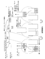
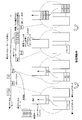
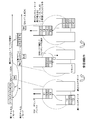
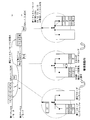
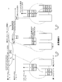
- FIG. 6 is a diagram for explaining still another operation example of the first embodiment.
- the figure explaining the operation example of 5th Embodiment The figure which shows the structural example of the radio
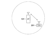
- FIG. 1 shows an example in which wireless terminals according to an embodiment of the present invention are connected to each other.
- a wireless terminal 201 STA201
- a wireless terminal 202 STA202
- the number of wireless terminals is not limited to two, and a plurality of wireless terminals may exist and each wireless terminal may be connected to a plurality of other wireless terminals.
- one of the two wireless terminals may be a wireless base station.
- the wireless base station 101 (AP 101) is connected to the wireless terminal 201 (STA 201).
- the wireless base station 101 may be connected to one or more wireless terminals other than the wireless terminal 201, or may be connected to one or more other wireless base stations, or connected to a wired network. It may be connected.
- the wireless terminal 201 may be connected to one or more wireless terminals other than the wireless base station 101.
- the radio base station is also described as a radio terminal.
- BSS Basic Service Set
- connection refers to a state in which the existence of each other is recognized and the mutual capability (Capability) necessary for realizing some wireless communication is grasped.
- Capability The mutual ability is grasped by, for example, notifying each other's ability between the wireless terminals.
- One means is through an authentication process. In the IEEE802.11 wireless LAN system, for example, this is an association process performed by exchanging management frames called association request and association response.
- the other means is a method of transmitting and grasping frames that notify each other of their abilities.
- this Beacon frame when transmitting a management frame called Beacon, which is also a synchronization signal and also has a role of indicating the attribute of the communication group (BSS), this Beacon frame has a field for notifying its own ability The other wireless terminal that has received the Beacon frame can thereby grasp the capability of the wireless terminal.
- a management frame similar to this Beacon frame there is a Probe Response frame that can be obtained as a response when a Probe Request frame is transmitted. The capability of the wireless terminal that is the transmission source can be grasped by this Probe Response frame.
- Wireless communication can be performed between wireless terminals in a connected state.
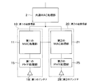
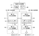
- FIG. 3 shows a configuration example of a wireless terminal according to an embodiment of the present invention.
- Each illustrated element forming the wireless terminal may be configured as hardware, may be configured as a software module, or may be configured by both of them.
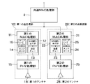
- the common MAC processing unit (frame distribution unit) 2 is connected to the first transmission / reception unit (first communication unit) 10 and the second transmission / reception unit (second communication unit) 20. Yes.
- the common MAC processing unit 2 for example, the first transmission / reception unit 10 or the second transmission / reception unit generates data generated via a logical link control (Logical Link Control; LLC) layer defined by the IEEE802 standard.
- LLC logical Link Control
- the transmission status of the frame sent from the first transmission / reception unit 10 or the second transmission / reception unit 20 is transferred to the LLC.
- the common MAC processing unit 2 performs control to pass the contents (payload) of the frame received via the first transmitting / receiving unit 10 or the second transmitting / receiving unit 20 to the LLC.
- the wireless terminal is a wireless base station
- the common MAC processing unit 2 may be connected to a wired network.
- the first transmission / reception unit 10 and the second transmission / reception unit 20 use different channels.
- the channel used by the first transceiver 10 corresponds to the first channel
- the channel used by the second transceiver 20 corresponds to the second channel.
- the channel is mainly a channel divided on the frequency, but may be a channel by code division or the like.
- the wireless terminal according to the present embodiment is a wireless terminal corresponding to a plurality of channels, that is, a multi-channel wireless terminal.
- the first transmission / reception unit 10 and the second transmission / reception unit may be distinguished by a frequency band level obtained by bundling a plurality of frequency channels.
- the first transmission / reception unit 10 may use any of the channels for 5 GHz band IEEE802.11a
- the second transmission / reception unit 20 may use any of the channels for 2.4 GHz band IEEE802.11b / g.
- Each channel in the 5 GHz band and the 2.4 GHz band does not need to be fixed, and the channel may be changed within the frequency band.
- the wireless terminal of the present embodiment is not only a different channel but also a multimode wireless terminal having a different transmission / reception method. Can be called.
- the first transmission / reception unit 10 and the second transmission / reception unit 20 may largely differ in transmission / reception method.
- the first transmission / reception unit 10 is based on the 60 GHz band IEEE802.15.3c wireless PAN standard
- the second transmission / reception unit 20 is based on the 5 GHz band IEEE802.11a wireless LAN standard. As is.
- the first transmission / reception unit 10 includes a first MAC (Media Access Control) processing unit 11, a first PHY processing unit 15, and a first antenna 18.
- first MAC Media Access Control
- the second transmission / reception unit 20 includes a second MAC processing unit 21, a second PHY processing unit 25, and a second antenna 28.
- the first MAC processing unit 11 and the second MAC processing unit 21 are connected to the common MAC processing unit 2, and MAC frame generation, access control during transmission, reception frame processing (including response frame transmission, etc.), Performs management and other processing related to settings between wireless terminals.
- These include, for example, IEEE802.11 wireless LAN (including a series of extended / complementary standards such as 802.11a, b, e, g, h, i, j, n, etc.) and IEEE802.15 wireless PAN (802.15.
- There are operations defined as the MAC layer including a series of extended and complementary standards such as 3 and 802.15.3c).
- the MAC processing units 11 and 21 may have a work area and a frame buffer, and may have a memory for wireless terminal information. These may be externally attached to the MAC processing units 11 and 21 instead of within the MAC processing units 11 and 21, and may be used for other processing than the MAC layer.
- management information that is shared by the first transmitter / receiver 10 and the second transmitter / receiver 20 such as information on wireless terminals to be connected by both the transmitter / receivers 10 and 20 is held by the common MAC processing unit 2.
- the wireless terminal to be connected is a multi-channel wireless terminal or a multi-mode wireless terminal having the capability of communicating with both the first and second transceivers.
- the role is divided so as to hold the setting information of the wireless terminal necessary for connection by the first / second transmission / reception unit 10/20. It may be.
- the common MAC processing unit 2 uses the first transmitter / receiver 10 to transmit the information based on terminal information managed internally and information acquired from the first / second MAC processing unit 11/21 if necessary. You may make it judge, such as distribution whether it transmits using the transmitter / receiver 20.
- FIG. 1 A block diagram illustrating an exemplary computing environment in accordance with the present disclosure.
- the first MAC processing unit 11 and the second MAC processing unit 21 are connected, but they may be connected via the common MAC processing unit 2 instead of being directly connected.
- the first PHY processing unit 15 and the second PHY processing unit 25 are respectively connected to the first MAC processing unit 11 and the second MAC processing unit 21, and generate PHY packets from the MAC frame, and perform modulation encoding. Processing, grasping the state of the wireless medium (air), demodulating and decoding the received signal, notifying the MAC processing unit of the received packet and reception state information, and the like. These are prescribed operations of the PHY layer in, for example, an IEEE802.11 wireless LAN system or an IEEE802.15 wireless PAN system.
- the PHY processing units 15 and 25 perform digital / analog conversion of the signal in order to radiate transmission packets as radio waves from the first antenna 18 and the second antenna 28, respectively, and gradually convert the frequency of the transmission signal Perform the process.
- the PHY processing units 15 and 25 perform step-by-step conversion of the frequency of the received signal and perform analog / digital conversion.
- data input from the LLC layer is distributed to the first transmission / reception unit 10 or the second transmission / reception unit 20 by the common MAC processing unit 2, and the MAC processing unit (the first MAC processing unit 11 or the first MAC processing unit in each transmission / reception unit).
- 2 MAC processing unit 21) is converted to a MAC frame
- PHY processing unit first PHY processing unit 15 or second PHY processing unit 25
- antenna It is transmitted as a radio signal from the first antenna 18 or the second antenna 28).
- the radio signal received from the antenna is the PHY processing unit (the first PHY processing unit 15 or the second PHY processing unit 25), the MAC processing unit (first The data is processed via the MAC processing unit 11 or the second MAC processing unit 21) and the common MAC processing unit 2, and the data addressed to the terminal is output to an upper layer such as the LLC layer.
- the wireless terminal according to the present embodiment is a multi-channel wireless terminal or a multi-mode wireless terminal having a first transmission / reception unit and a second transmission / reception unit.
- the system as shown in FIG. 1 or FIG. 2 may be composed of only the multi-channel / multi-mode wireless terminals of the present application, or non-multi-channel / non-multi-mode wireless terminals may be mixed.
- the present invention is directed to the case where frames are transmitted and received using a plurality of channels between multichannel / multimode wireless terminals.
- the MAC frame is roughly divided into three types, a data frame, a management frame, and a control frame. These types are indicated in a type field in the frame control field of the MAC header part. Further, a subtype field is provided in the frame control field in order to distinguish individual frame types.
- a data frame is basically a frame generated from data passed from the upper MAC layer (for example, LLC layer). In some cases, for example, empty data is generated in the MAC layer, and a frame generated in the future is used as a data frame.
- the upper MAC layer for example, LLC layer.
- empty data is generated in the MAC layer, and a frame generated in the future is used as a data frame.
- Management frame is a frame for transmitting management information at the MAC layer level.
- Beacon frame For example, there are the aforementioned Beacon frame, Probe request frame, Probe response frame, Association request frame, Association response frame, and the like.
- the control frame is a frame used for access control in the MAC layer.
- RTS frame for channel reservation before sending data frame or management frame and CTS frame that is the response frame (CTS frame can also be transmitted alone for direct channel reservation)
- delivery confirmation Ack Acknowledgment
- BA Block Acknowledgment
- BAR Block Acknowledgment Request
- the MAC frame in IEEE802.11 is passed to the PHY layer as an MPDU with a frame configuration as shown in FIG. FIG. 4 shows a general frame structure, and some fields may not exist depending on the frame.
- a data frame before such a frame structure is called MSDU (MAC Service Data Unit), and a management frame before such a frame structure is called MMPDU (MAC Management Protocol Data Unit).
- MSDU MAC Service Data Unit
- MMPDU MAC Management Protocol Data Unit
- MSDU and MMPDU are given a sequence number which is the order of frames. Specifically, the order is described in the sequence number field (Sequence Number field) in the sequence control field (Sequence Control field) of the MAC header when it becomes an MPDU.
- a sequence number field Sequence Number field
- Sequence Control field Sequence Control field
- a counter is provided for each direct destination address for each TID, and the sequence number of the frame is incremented by one.
- a QoS Null frame may be a QoS (+) Null frame including the addition of an ACK response
- a counter different from MSDU is prepared for the MMPDU, and a sequence number is given.
- MSDU and MMPDU when MSDU and MMPDU become MPDU, they may be divided into short frame length fragments as necessary (fragment processing).
- the fragment number is also assigned to the fragment number field (Fragment Number field) in the sequence control field of the MAC header in order to reconstruct the unit MSDU and MMPDU (defragment processing) on the receiving side.
- FCS Frame Check Sequence
- the FCS at the end is formed from the Cyclic Redundancy Code (CRC)
- CRC Cyclic Redundancy Code
- the CRC is a Frame that contains the MAC header, data from LLC, etc. It is a value calculated from the Body field.
- the reception side checks the CRC, and if an error is detected, subsequent reception processing such as extraction of the address of the transmission destination wireless terminal is not performed.
- access to the channel is basically performed after a fixed time of EIFS (Extended InterFrame Space) waiting for the expected maximum time assuming transmission of an acknowledgment response (an ACK frame described later). If no error is detected as a result of the CRC check, the reception process is continued. For example, if the direct destination address is not addressed to the terminal itself, NAV (Network Allocation) is used to activate virtual carrier sense for a certain period of time based on the Duration / ID field and Subtype field described in the MAC header. Set Vector).
- EIFS Extended InterFrame Space
- ACK Acknowledgment
- SIFS Short-InterFrame-Space
- DA Destination Address
- MA-UNITDATA service primitive
- the address of the direct destination wireless terminal is written in the first address field (Address 1 field in FIG. 4) of the MAC header.
- the final destination address varies depending on the situation, it is Address 1 or enters Address3 if the final destination and the direct destination address are different.
- the final destination address may be described in the Address 1 field.
- the address of the direct transmission source wireless terminal of the frame is written in the second address field (Address 2 field in FIG. 4) of the MAC header in the IEEE802.11 wireless LAN.
- BSSID wireless communication group identifier
- Address 1, Address 2, and Address 3 in FIG. 4
- the address field in which the identifier of the wireless communication group is entered differs depending on the role of each wireless terminal that transmits and receives within the wireless communication group.
- the wireless base station may be a wireless terminal that can transfer data from other terminals (including terminals connected by wire in addition to wireless terminals.
- wireless base stations are included).
- a plurality of wireless communication groups can be combined to construct one wireless communication system (Extended Service Set; ESS). And between wireless communication groups in this wireless communication system is called Distributed System (DS).
- the DS may be wired or wireless, but the wireless base station can also be defined as a wireless terminal that can be connected to the DS.
- the wireless terminal that transmits is a wireless base station
- the wireless terminal that receives a data frame is a non-wireless base station (non-wireless base station). If it is a wireless base station terminal), the identifier of the wireless communication group is set in the Address 2 field, and when the non-wireless base station terminal transmits a data frame to the base station terminal, the identifier of the wireless communication group is It is designed to be entered in the Address 1 field.
- the wireless communication group identifier is set in Address 3 (when the wireless terminal 202 communicates).
- the identifier of the wireless communication group is set in Address 3. For example, in the IEEE802.11 wireless LAN as shown in FIG. 1, the identifier of the communication group is determined by the random number of the wireless terminal that started the communication group.
- ⁇ Example of filtering by communication group identifier> When a received frame is received from the PHY layer, it is checked whether a normal frame is received by CRC check or the like. After that, it is determined by looking at a predetermined address field whether the identifier of the wireless communication group is the same as the identifier of the wireless communication group to which the own wireless terminal belongs according to the frame type for the frame determined to be normal. May include actions.
- Block Ack Mechanism> In IEEE802.11 wireless LAN, there is a mechanism in which delivery confirmation responses to a plurality of data frames are collectively transmitted, and a non-reachable data frame is retransmitted in a transmitting wireless terminal that has received the delivery confirmation response. This is called the Block Ack (BA) mechanism.
- the BA mechanism can be applied to QoS data frames in which TID (traffic type) is distinguished.
- TID traffic type
- MA-UNITDATA.request used when the MAC layer receives data from the upper layer, a priority parameter is entered as a variable together with the data, and the value is handled in the MAC layer as a TID.
- the TID is expressed as an integer from 0 to 15, and the priority order of access rights is assigned based on this TID.
- TIDs are assigned as appropriate according to the purpose of use. ).
- the receiving wireless terminal does not necessarily receive the data frames in the order of the sequence number. Therefore, in order to pass the data from the MAC layer to the upper side in the same order as the receiving side received from the upper side, A mechanism for rearranging them in order is required.
- the part that performs this reordering process is called a receive reordering buffer control part, particularly for a scoreboard context control part in IEEE802.11n described later.
- the receive reordering buffer control unit is abbreviated as a reordering buffer (reordering buffer).
- a reordering buffer is provided for each different TID. This is because sequence numbers are assigned differently in frames with different TIDs.
- the reception confirmation response reception status part for holding this reception status is called the above-mentioned scoreboard-context-control part.
- Scoreboard context control is abbreviated as scoreboard.
- the scoreboard is also referred to as a reception status storage unit.
- the scoreboard is also provided for each different TID because the sequence numbers are assigned differently in frames with different TIDs.
- the reception status is notified to the wireless terminal on the data transmission side using a BA (Block Ack) frame as shown in FIG.
- a BA Block Ack
- a method for a transmitting side wireless terminal to request a BA frame from a receiving side wireless terminal there are a method of transmitting and requesting a Block Ack Request) (BAR) frame that is a control frame, and a method of placing a request inside data to be transmitted. is there.
- the former is called explicit block request ⁇ request, and the address information of the requesting wireless terminal and the requesting wireless terminal, the information on which TID frame is requested, and the delivery confirmation response from where the sequence number is requested ( Information of Starting (Sequence Number; SSN) is shown in the BAR frame and a delivery confirmation response is requested.
- SSN Sequence Number
- the latter is called “implicit block request”, and requests a delivery confirmation response from the receiving wireless terminal in combination with a field for specifying the type of the delivery confirmation response of the data to be transmitted and the form of the frame to be transmitted.
- a transmission form using an aggregation method in which a plurality of MPDUs are collectively put into a PHY packet as one MPDU (a form in which the plurality of MPDUs are collected is called aggregateagMPDU (A-MPDU))
- A-MPDU aggregateagMPDU
- the receiving wireless terminal stores the reception status information held for the TID of the data indicating the Normal-Ack policy in BA Notify the sending wireless terminal in a frame.
- the TID of each data frame is shown in the QoS control (QoS / Control) field of FIG.
- an SSN Startting Sequence Number
- the reception status is assigned to each MSDU in the order of the sequence number from the relevant SSN (compressed), or to each MPDU in the order of the fragmentation number in the corresponding sequence number location (basic). Indicated by Block Ack Bitmap.
- the receiving wireless terminal of the data frame sets 1 in the corresponding block Ack Bitmap for the received frame, and the frame that has not been received or does not have a reception status (for example, the location of an unused fragment number or retention) If the area other than the scoreboard is returned in the bitmap, this is the case.) Set the corresponding part of Block Ack Bitmap to 0.
- Block Ack Bitmap will be explained mainly using the former case of notifying the delivery confirmation response in MSDU units (compressed) (in this case, the data transmission side will not perform fragmentation), The basic operation does not change even when the fragmentation number information is (basic).
- ⁇ Variation related to selective retransmission in multi-channel / multi-mode> When using the selective retransmission method between multi-channel / multi-mode wireless terminals, ⁇ Whether the sequence number is unified between channels / modes or can be assigned separately. ⁇ Whether the reordering buffer is provided in common for both channels / modes or separately, ⁇ Whether to use the same wireless terminal address for both channels / modes -Whether the traffic type (TID) is common or changeable in both channels / modes.
- TID traffic type
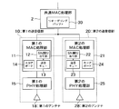
- the configuration of the wireless terminal according to the first embodiment is as shown in FIG. 6 based on FIG.
- the reordering buffer 30 is in the common MAC processing unit 2, and the sequence number assigning units (SN assigning units) 12 and 22 are in the first MAC processing unit 11 and the second MAC processing unit 21, respectively, and the sequence number assigning unit A transmission frame is put into the transmission queues 13 and 23 via 12 and 22. Further, scoreboards 14 and 24 holding reception status when operating as a receiving side are also provided in the first MAC processing unit 11 and the second MAC processing unit 21, respectively.
- MSDU is transmitted Is as follows. That is, the MSDU is distributed from the common MAC processing unit 2 to the first MAC processing unit 11 or the second MAC processing unit 21 to form an MPDU, and then the transmission queue 13 or SN via the SN allocation unit 12 or the SN allocation unit 22 It is placed in the transmission queue 23.
- the MPDU in the transmission queue 13 or the transmission queue 23 is changed to the first PHY processing unit 15 or the second PHY processing unit 15 To the PHY processing unit 25 and transmitted from the first antenna 18 or the second antenna 28.
- the first MAC processing unit or the second MAC processing unit from the first antenna 18 or the second antenna 28 via the first PHY processing unit 15 or the second PHY processing unit 25
- the frame is input as an MPDU.
- the sequence number of the frame received normally (or the fragment number in the part corresponding to the corresponding sequence number in some cases) if the frame is a data frame and requires a delivery acknowledgment response by the Block Ack mechanism Record that it has been received in the corresponding part of the scoreboard 14 or scoreboard 24 (specifically, the scoreboard usually has the same bitmap structure as Block Ack bitmap and the corresponding sequence number (or Depending on the sequence number, the corresponding bit portion of the portion corresponding to the sequence number is set to 1.
- this configuration will be described as a premise).
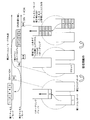
- the transmission side wireless terminal first has a sequence number corresponding to the channel to which the first transmitter / receiver 10 corresponds (this will be referred to as the first channel here. Of course, the mode may be the first mode in this case).
- Each frame 1 to 5 is transmitted by A-MPDU.
- the A-MPDU includes an implicit block block request.
- the receiving side wireless terminal When the receiving wireless terminal receives the A-MPDU by the first transceiver 10, the receiving side wireless terminal records the sequence number of the normally received frame on the scoreboard (first scoreboard) 14 in the first MAC processing unit 11. .
- the frame with sequence number 1 in the A-MPDU was received normally, but the other frames were not received normally and the sequence number could not be grasped, so the bit corresponding to sequence number 1 on the scoreboard 14 Just set 1 to the part and leave the others as 0.
- the received frame is sent to the reordering buffer 30 which is common between the channels / modes. If the starting sequence number (Starting Sequence Number; SSN) is set to 1 when the Block Ack mechanism is set, the reordering buffer 30 sets the minimum sequence number in the frame waiting state to 1. For this reason, when a frame with a sequence number of 1 enters the reordering buffer 30, this sequence number 1 matches the minimum sequence number in the standby state, so this frame is transferred from the MAC layer to the upper layer (LLC layer). To pass. Then, the minimum sequence number in the frame waiting state is set from 1 to the next 2 (incremented by 1).
- SSN Startting Sequence Number
- A- Generate Block Ack (BA) frame from implicit block ack request shown in MPDU reflect the contents of scoreboard 14 to Block Ack Bitmap in BA frame, and receive fixed time after receiving A-MPDU (IEEE802.11 In wireless LAN, BA frame is transmitted after SIFS (fixed time). In FIG. 7, it is notified that the frame of sequence number 1 has been normally received by the BA frame.
- SIFS fixed time
- the transmitting wireless terminal determines that frame dropping is severe in communication using the first channel / mode, and the subsequent data transmission is performed by the second transceiver 20 corresponding to the channel /
- a mode here, this is called a second channel / mode.
- the first transmitter / receiver 10 of the transmission side wireless terminal manages the delivery status of the transmission frame from the delivery confirmation response frame from the reception side wireless terminal, and the communication quality does not satisfy a certain standard in the first channel / mode.
- the second transmitter / receiver 20 has decided to change the transmission source. The same function can be determined by changing the second transceiver 20 to the first transceiver 10 by providing the second transceiver 20.
- the transmitting side wireless terminal determined in this way moves the frames of sequence numbers 2 to 5 from the first MAC processing unit 11 to the second MAC processing unit 21. More precisely, the frames of sequence numbers 2 to 5 that were in the transmission queue 13 in the first MAC processing unit 11 are passed through the sequence number assigning unit 22 of the second MAC processing unit 21 and new frames are added to these frames. A process of assigning a channel / mode sequence number to each and putting them in the transmission queue 23 is performed. At this time, the frame newly assigned by the second MAC processing unit 21 to the frame having the smallest sequence number among the frames transferred from the first MAC processing unit 11, that is, the frame having the sequence number 2 in FIG. The number is held in the second MAC processing unit 21. In the example of FIG. 7, the sequence number is 1.
- the transmitting wireless terminal notifies the receiving wireless terminal that the channel / mode is changed.
- notification is performed using a management frame (represented as “Mg” in FIG. 7) different from a data frame in which a series of data exchange is performed. This is not for the purpose of transmitting data but for managing the operation of the wireless terminal.
- a management frame represented as “Mg” in FIG. 7
- TID traffic type
- the channel / mode for transmitting the notification frame is the second channel / mode to be switched to. This is because frame dropping is severe in the first channel / mode, so that there is a higher possibility that a management frame can be delivered properly if transmission is performed in the second channel / mode, which is expected to have high reliability.
- the sequence number (SSN) for starting transmission in the change destination channel / mode is the frame transferred from the first MAC processing unit 11 that has been held, and the frame with the minimum sequence number is the second MAC processing unit 21. It is the newly assigned sequence number (here 1).
- the TID of the data frame subject to channel / mode change is not clear at the receiving wireless terminal only by the notification information, the corresponding TID information is put in the notification frame.
- the target TID becomes clear at the receiving wireless terminal and can be omitted. In addition, this is not the case when the frame type (Subtype) of the management frame itself to be notified is changed corresponding to the TID of the target data frame.
- a received wireless terminal transmits an Ack frame after SIFS time in a frame (unicast frame) transmitted to a single wireless terminal. Since it is not used, it is expressed as “Ack” in FIG.
- the receiving wireless terminal that has received the notification frame to change the channel / mode, a process for raising all the received frames in the reordering buffer 30 in the common MAC processing unit 2 from the MAC layer to the upper layer (LLC layer) Then, the minimum sequence number in the frame waiting state is set to the transmission start sequence number notified in the frame.
- the receiving wireless terminal specifies the transceiver (in this case, the first transceiver 10) corresponding to the channel / mode in which the corresponding TID frame was exchanged with the transmitting wireless terminal. It is desirable to reset the scoreboard 14 in the MAC processing unit (in this case, the first MAC processing unit 11) of the corresponding transceiver. This is because, by resetting the scoreboard 14, the scoreboard 14 can be utilized for receiving another wireless terminal or another TID frame.
- the transceiver corresponding to the channel / mode in which the corresponding TID frame was exchanged with the transmitting wireless terminal There are the following methods for specifying the transceiver corresponding to the channel / mode in which the corresponding TID frame was exchanged with the transmitting wireless terminal. First, there is a method in which the TID is identified from the notification frame, and the transceiver that has processed the TID until the notification frame is received is determined in the common MAC processing unit 2 or the like.
- the notification frame includes information on which channel / mode to switch to (in this example, the second channel / mode)
- the wireless terminal has only two channels / modes
- the channel / mode not exclusively indicated as the switching destination is determined to be the channel / mode in which the corresponding TID frame is exchanged with the transmitting wireless terminal, and the determined channel / mode
- the transmitting wireless terminal transmits the notification frame and receives a response frame to the notification frame
- the transmitting wireless terminal transmits a frame from the second transceiver 20 corresponding to the second channel / mode. These frames are obtained by re-sequencing the sequence numbers of the frames having the sequence numbers 2 to 5 transmitted in the first channel / mode to the sequence numbers 1 to 4 by the second MAC processing unit 21 and retransmitting them.
- the response frame for the notification frame is an Ack frame, but the receiving wireless terminal separates the Ack frame from the response frame for the notification frame (the notification frame is managed when the processing of the reordering buffer 30 is completed).
- a management frame may be transmitted, and the transmitting wireless terminal may transmit the frame in the channel / mode to be changed after receiving the response frame.
- the receiving wireless terminal When the receiving wireless terminal receives the frame in the second channel / mode, it records the reception status on the scoreboard 24 of the second MAC processing unit 21 and raises the received frame to the reordering buffer 30 of the common MAC processing unit 2 .
- the score board 24 records that frames with sequence numbers 1 to 4 were normal, and Frames with sequence numbers 1 to 4 are sequentially passed from the ordering buffer 30 to the upper layer of the MAC layer.
- the sequence numbers 1, 2, 3, 4, and 5 are received in order.
- FIG. 7 shows an example in which the frames with the sequence numbers 2 to 5 in the first MAC processing unit 11 are transferred to the second MAC processing unit 21 and transmitted. However, the subsequent frames with the same TID are higher in the MAC layer. Is passed from the common MAC processing unit 2 to the second MAC processing unit 21, and a continuous sequence number (from sequence number 5 in this example) is assigned.
- FIG. 7 shows an example in which there is a frame to be transferred from the first MAC processing unit 11 to the second MAC processing unit 21, but a frame of a certain TID is originally transmitted from the first MAC processing unit 11. There is no frame to be transferred from the first MAC processing unit 11 to the second MAC processing unit 21, but the transmission of the same TID frame is switched to the transmission from the second MAC processing unit 21 from the next Operates as follows. That is, when the data frame passed from the upper layer of the MAC layer is distributed by the common MAC processing unit 2, the data frame of the TID is passed to the second MAC processing unit 21. Then, before transmitting the data frame of the TID in the second channel / mode, the minimum sequence number assigned by the sequence number assigning unit 22 of the second MAC processing unit 20 is notified by the notification frame. Other operations are the same as described above.
- FIG. 7 shows a case where the latter half of the transmission is not continuously received by the receiving wireless terminal, but there are other cases where the receiving state is not. Therefore, consider the case shown in FIG.
- the transmitting wireless terminal is transmitting frames with sequence numbers 11-15.
- the receiving wireless terminal normally receives sequence numbers 11 and 13, and the reception status is recorded in the first scoreboard 14.
- 1 is set at the position corresponding to the sequence number 11 that has been normally received
- 12 is set between the sequence numbers 11 and 13 and 0 is set as unreceived
- the sequence number 13 that has been normally received is set at 1 at the corresponding position.
- a BA frame notifying that the frames of sequence numbers 11 and 13 have been received is transmitted by an implicit block request ack request.
- the received frames having sequence numbers 11 and 13 are raised to the reordering buffer 30 in the common MAC processing unit 2.
- the frame with the sequence number 11 is passed from the MAC layer to the upper layer. Since the frame with sequence number 12 has not been received, the reordering buffer 30 changes the minimum sequence number in the frame waiting state to 12, and retains the frame with sequence number 13.
- the transmitting wireless terminal stops transmitting in the first channel / mode and decides to transmit in the second channel / mode, the transmitting wireless terminal notifies the switching as in the example in FIG. Send the frame to the receiving wireless terminal.
- the receiving wireless terminal that has received the notification frame performs the same processing as described above. Particularly in this example, since the frame of sequence number 13 is held in the reordering buffer 30 while waiting for reception of the frame of sequence number 12, the frame of sequence number 13 is transferred from the MAC layer to the upper layer.
- the transmitting side wireless terminal knows that the sequence numbers 12, 14, and 15 transmitted in the first channel / mode are not received by the receiving side wireless terminal.
- Frames to be retransmitted after switching to the second channel / mode are frames with sequence numbers 14 and 15, and there is a gap between sequence numbers 11 and 13 that are normally received in the reception status indicated by the BA frame 12 Is not retransmitted in the second channel / mode.
- Frames transmitted as sequence numbers 14 and 15 in the first channel / mode are assigned sequence numbers 1 and 2 in the second channel / mode and transmitted.
- the receiving side wireless terminal normally receives the frames assigned with these new sequence numbers 1 and 2, and raises them to the higher level via the reordering buffer 30. Considering the sequence numbers in the first channel / mode, sequence numbers 11, 13, 14, and 15 are received.
- the reception status from sequence number 11 is returned in the BA frame. For example, if only the reception status from sequence number 13 is returned, both the sequence numbers 11 and 12 are not received by the receiving wireless terminal. In this case, the frame of the missing portion is that of sequence numbers 11 and 12.
- the frame of the missing part is not received by the receiving wireless terminal after the above-mentioned channel / mode changing process. To prevent this, the missing part is retransmitted before the channel / mode changing process is performed.
- the same channel / mode here, the first channel / mode
- FIG. 9 shows a case where the transmitting wireless terminal cannot clearly determine whether the receiving wireless terminal has received a frame.
- the transmitting wireless terminal transmits frames with sequence numbers 11 and 12 in A-MPDU in the first channel / mode, and the receiving wireless terminal normally receives the frame with sequence number 11 as a BA frame. A response is returned.
- the receiving radio terminal performs processing for raising the frame number 11 data from the reordering buffer 30 to the upper layer of the MAC layer. In this situation, the transmitting side wireless terminal knows that the frame of sequence number 12 has not been received by the receiving side wireless terminal, and there is no discrepancy in the situation recognition with the receiving side wireless terminal.
- the transmitting wireless terminal retransmits the frame of sequence number 12 in the form of requesting an Ack frame of immediate response in the first channel / mode (in this case, 1 is set in the retry bit described later).
- the receiving wireless terminal receives the frame with the sequence number 12 and transmits an Ack frame, and raises the frame with the sequence number 12 to the reordering buffer 30.
- the sequence number 12 is next to the sequence number 12. Since the frames are coming in order, the frame with the sequence number 12 is sent to the process for raising it to the upper layer of the MAC layer.
- the transmitting wireless terminal cannot obtain confirmation that the receiving wireless terminal has received the frame of sequence number 12.
- the transmitting side radio terminal changes the channel / mode at this stage, it is not possible to transmit the frame of sequence number 12 that has been received by the receiving side radio terminal and has no confirmation in the channel / mode to be changed. This is because the receiving-side wireless terminal cannot recognize that the frame with the different sequence number transmitted in the channel / mode to be changed is the same as the frame with the sequence number 12 received before, that is, duplicate reception of data. It is.
- frames with sequence numbers after 13 that have not yet been transmitted in the first channel / mode are reassigned to the sequence numbers starting from 1 in the second channel / mode and transmitted. If these frames are normally received by the receiving wireless terminal, considering the sequence numbers in the first channel / mode, the receiving wireless terminal will eventually end up with sequence numbers 11, 12, 13, 14, 15 Will be received.
- the receiving wireless terminal has transmitted an Ack frame for the frame of sequence number 12 received in the first channel / mode, but the frame of sequence number 12 is a frame of TID for which the Block-Ack mechanism is set. Therefore, the reception status is recorded on the score board 14 as shown in FIG. Therefore, if the transmitting side wireless terminal requests that the reception status for the frame from sequence number 11 or 12 is transmitted in the BA frame, it can be notified that the frame of sequence number 12 has been received by the BA frame. it can. Therefore, for sequence number 12 for which there is no confirmation of reception before the channel / mode change, a request is made to retransmit in the same channel / mode as described above, or to return the reception status including sequence number 12 in a BA frame. The reception status of sequence number 12 can be reconfirmed by a method such as
- the frame having the sequence number 12 is transmitted in the form of requesting the Ack frame, but one frame having the sequence number 12 is set as an A-MPDU (in this case, the PHY packet has a plurality of MPDUs).
- the Ack frame is changed to a BA frame.
- the BA frame cannot be confirmed in the same manner unless the frame itself is lost and the frame itself can be grasped.
- the frames that can be retransmitted at the channel / mode change destination by the transmitting wireless terminal are consecutive from the smallest sequence number of untransmitted frames and smaller than the smallest sequence number.
- This is a transmitted frame having a number and a frame that has not been received by the data transmission destination wireless terminal (a frame that has received a reception status notification that has not been received from the data reception side wireless line terminal).
- untransmitted frames are transmitted by changing the channel / mode even if they are already in the transmission queue of one MAC processing unit (the MAC processing unit before the change) before the channel / mode change. There are no restrictions.
- a retry bit in the frame control field of the MAC header is set, but this is the same as when a retry bit frame is received. This is in order to confirm a duplicate of whether or not a frame has been received.
- the frame of the missing portion as shown in FIG. 8 and the frame that has arrived or has not been confirmed as shown in FIG. 9 are given up in another channel / mode. There is no need to perform transmission processing such as setting a retry bit and retransmitting these frames in the previous MAC processing unit.
- transmission processing is performed such that transmission is performed with a retry bit set in the change destination channel / mode. There is no need. Of course, this is not the case when a frame is retransmitted in the same channel / mode as the change source, and a retry bit is set.
- the receiving-side wireless terminal does not need to manage duplicate frames having different sequence numbers and overlapping data contents between the first transceiver and the second transceiver.
- the receiving wireless terminal transmits and receives data corresponding to the specified channel.
- the vessel can be specified.
- the reception-side wireless terminal can make preparations for frame reception. That is, the receiving wireless terminal can receive the frames transmitted by switching between channels / modes in order. This means that even when the transmission order is changed in the MAC layer, it is possible to return the order in the MAC layer without depending on the sequence in the upper layer.
- the transmitting side wireless terminal can reduce the burden of frame preparation just before the access control unit (the part close to the 1/2 PHY processing unit in each 1/2 MAC processing unit).
- the movement of the transmission frame can be flexibly performed, and the reception-side wireless terminal can prevent the processing from being complicated when the reception frames from different frequency bands / channels are rearranged in the order of transmission. Therefore, it becomes possible to flexibly cope with a sudden disconnection of the communication link in one frequency band / channel.
- the reception side wireless terminal can release the frequency band / channel buffer that is no longer used due to the notification from the transmission side wireless terminal, thereby improving the efficiency of memory utilization.
- the second embodiment differs from the first embodiment in that the change notification frame is transmitted in the change destination channel / mode instead of including the change destination channel / mode information in the channel / mode change notification frame. It is to be.
- the channel / mode change notification frame represented as “Mg” in FIG. 7 used in the first embodiment is transmitted in the change destination channel / mode.
- the channel / mode change notification frame represented as “Mg” in FIG. 7 used in the first embodiment is transmitted in the change destination channel / mode.
- the channel / mode is changed when it is in a situation inappropriate for communication such as a large number of dropped frames in the currently used channel / mode.
- the earlier channel / mode can be expected to establish a more suitable communication link with the receiving wireless terminal than before the change. Therefore, by transmitting the change notification frame in the channel / mode of the change destination, it can be expected that the reception-side wireless terminal reliably receives the change notification frame.
- a channel / mode change notification frame is transmitted to the receiving wireless terminal, a response frame is received, and then a data frame is transmitted in the channel / mode to be changed.
- the channel / mode after knowing that the receiving wireless terminal has surely received the change notification frame (note that the response frame is an Ack frame for the change notification frame).
- the response management frame may be used. If no response frame is received, the transmitting wireless terminal reviews whether or not the channel / mode has been changed, stops changing the channel / mode according to the result of the examination, and transmits (retransmits) the data frame in the same channel / mode. ) May be performed. In this way, the data frame can be transmitted to the receiving wireless terminal by a more reliable method.
- the receiving-side wireless terminal that has received the change notification frame transmits a response frame, and the corresponding channel / mode of the transceiver that has received the change notification frame is changed in the future to which the corresponding data frame is transmitted. Recognize when it becomes channel / mode. For example, in the example of FIG. 7, since the change notification frame is received by the second transceiver, it is recognized that the data frame of the TID will be transmitted in the future by the second channel / mode corresponding to the second transceiver. To do. Then, as described in the first embodiment, a series of processing such as operation of a reordering buffer for data frame reception is performed.
- the receiving wireless terminal reliably receives the change notification frame. It is possible to change the channel / mode after knowing that this has been done. If no response frame is received, the transmitting wireless terminal reviews whether or not the channel / mode has been changed, and the data frame in the original same channel / mode is stopped according to the result of the examination, and the channel / mode change is stopped. By retransmitting the data frame, the data frame can be transmitted to the receiving wireless terminal by a more reliable method.
- the third embodiment differs from the first embodiment in that the channel / mode change notification frame corresponds to the change source channel / mode, strictly speaking, the change source transceiver in the transmission side wireless terminal. Information.
- the channel / mode represented by “Mg” is displayed.
- the change notification frame the fact that the first channel / mode is the change source channel / mode is entered.
- the receiving wireless terminal that has received the change notification frame can easily identify the corresponding change source transceiver directly from the change source channel / mode information specified in the change notification frame.
- processing to determine which transceiver has exchanged (transmitted / received) the same TID data frame so far, and exclusive transmission / reception of the transceiver corresponding to the change destination channel / mode from the change destination channel / mode information There is no need to perform processing such as grasping the vessel.
- the process of specifying the source transceiver is simplified. After specifying the change destination transceiver, the processing described in the first embodiment can be performed on the change source transceiver.
- the receiving wireless terminal that has received the change notification frame receives the change source channel / mode information specified in the change notification frame.
- the transmitter / receiver of the change source can be easily identified directly. In other words, it is necessary to know which transceiver has exchanged (transmitted / received) the same TID data frame until now, and exclusive transmission / reception of the transceiver corresponding to the change destination channel / mode from the change destination channel / mode information. There is no need to grasp the vessel. In particular, when there are three or more transceivers corresponding to different channels / modes, the process of specifying the source transceiver is simplified.
- the difference of the fourth embodiment from the first embodiment is that in the first embodiment, the information of the transmission start sequence number for starting transmission in the channel / mode to be changed is described in the change notification frame. In the fourth embodiment, an operation that can be omitted with respect to the transmission start sequence number is provided.
- the sequence number assignment unit initializes the sequence number to 0 Suppose that Or, even if it is not 0, another fixed sequence number is assigned as a default value. When it is guaranteed between the transmitting and receiving terminals that such an operation is surely performed, it is not necessary to put a transmission start sequence number for starting transmission in the change destination channel / mode in the change notification frame, and can be omitted. .
- the default value may be notified when the setting for the Block Ack mechanism is performed between the wireless terminals. If the length of the setting frame is limited, for example, in bytes, it is possible that unused fields (reserved fields) have been left so far, and if such fields can be used, communication efficiency will be improved. be able to.
- the channel / mode change notification frame represented as “Mg” information indicating that the second channel / mode to be changed starts from sequence number 1 ( For example, when the transmitting wireless terminal moves a frame between the first and second transceivers 10 and 20, the sequence number at the destination is set.
- sequence number 1 For example, when the transmitting wireless terminal moves a frame between the first and second transceivers 10 and 20, the sequence number at the destination is set.
- frames with sequence numbers 2 to 5 in the first channel / mode are sequentially assigned sequence numbers 0 to 3 in the second channel / mode to be changed.
- the receiving wireless terminal that has received the change notification frame determines that the transmission start sequence number in the second channel / mode to be changed is a default value, which is 0 here, and is described in the first embodiment hereinafter. Process.
- the transmitter / receiver at the receiving wireless terminal does not need to include the transmission start sequence number of the destination transceiver in the change notification frame. It is possible to perform a reception process corresponding to the change.
- the fifth embodiment is different from the first embodiment in that the transmission start sequence number in the change destination channel / mode is not notified in the change notification frame, but transmission is started in the change destination channel / mode. The difference between the sequence number in the frame change source channel / mode and the transmission start start sequence number is notified.
- FIG. 10 in which FIG. 8 used in the first embodiment is modified for the fifth embodiment.
- the transmitting wireless terminal transmits a data frame with sequence numbers 11 to 15 in the first channel / mode and receives a BA frame with a reception status indicating that the data frames with sequence numbers 11 and 13 have been received. Receive from.
- the frame of sequence number 11 is sent to the process of passing from the MAC layer to the upper layer (LLC layer), and the minimum sequence number of standby is set. 12
- the transmitting side wireless terminal decides to switch to the second channel / mode to perform transmission, and in order from the frame of sequence number 12 that has not been received in the first channel / mode, the second channel / mode It will be sent by.
- the receiving-side wireless terminal that has received the change notification frame raises all received frames in the reordering buffer 30 to the upper layer and then notifies the minimum sequence number in the frame waiting state. An operation to set the start sequence number was performed.
- the received data frame is raised to the upper layer from the change destination transceiver (here, the second MAC processing unit 21) to the reordering buffer 30 in the common MAC processing unit 2, Based on the notified difference value, correction processing of the sequence number of the received data frame is added (in FIG. 10, “SN is corrected by +11 to indicate reordering”).
- a correction processing block for passing a received frame may be added on the interface between the second MAC processing unit 21 and the common MAC processing unit 2 in FIG.
- a correction processing block may be provided on the second MAC processing unit 21 side.
- a correction processing block may be provided on the common MAC processing unit 2 side.
- the same processing is performed for passing the received data frame from the first transceiver 10 to the common MAC processing unit 2 in the same manner.
- the part to be performed (correction processing block) is necessary.
- the transmitting wireless terminal After transmitting the channel / mode change notification frame (after receiving a response if a response is required), the transmitting wireless terminal transmits data frames with sequence numbers 1, 3, and 4 in the second channel / mode. Send. These correspond to the data frames of sequence numbers 12, 14, 15 in the first channel / mode, respectively.
- the receiving wireless terminal that has normally received sequence numbers 1, 3, and 4 in the second channel / mode notifies the transmitting wireless terminal to that effect with a BA frame and raises the received frame to the reordering buffer 30.
- the receiving wireless terminal corrects the received sequence number with the notified difference value.
- the data frames of sequence numbers 1, 3, and 4 are corrected by the difference value “ ⁇ 11” to be sequence numbers 12, 14, and 15, and are put into the reordering buffer 30. Since the sequence number 12 that could not be received in the first channel / mode was received in the second channel / mode, the frames are passed in the order of sequence numbers 12 to 13, 14, and 15 (note that the sequence number 13 Has been received on the first channel / mode).
- the data frame notified as unreceived in the first channel / mode in the receiving wireless terminal is retransmitted in the second channel / mode, but the frame notified as already received is transmitted in the second channel / mode. You may retransmit in mode.
- a frame with sequence number 13 in the first channel / mode may be retransmitted as sequence number 2 in the second channel / mode.
- the frame received in the second channel / mode and having the sequence number corrected to 13 is discarded because it is already stored in the reordering buffer 30. Therefore, there is no problem even if this is done.
- the reordering buffer 30 has already raised the minimum sequence number for frame waiting to sequence number 12, and since the corrected sequence number 11 is smaller than the minimum sequence number 12 for standby, the sequence number 11 The frame is discarded, so there is no problem.
- a frame / mode can be changed and retransmitted even for a frame received by the receiving wireless terminal or not verified.
- the process “sequence number ⁇ ” is performed.
- the difference criterion is the source of change in the above description, any criterion may be used as long as the same correction can be finally made. For example, if the reference is the change destination, in this example, the difference is 11 instead of -11, and a correction process of “sequence number + ⁇ ” may be performed on the frame received in the change destination channel / mode.
- the difference information is notified of the change.
- it may be notified in advance to the receiving wireless terminal.
- the receiving wireless terminal receives the channel / mode change notification frame, it may perform the correction operation as described above using the difference value notified in advance.
- the first embodiment is notified by notifying the difference value between the start sequence number of the frame that starts transmission at the change destination transceiver and the sequence number at the transmission source transceiver of the frame. Then, it becomes possible to retransmit a frame that could not be retransmitted by the change destination transceiver (change destination channel / mode) (in the first embodiment, it was possible to retransmit consecutively dropped frames up to untransmitted frames). ). For example, even a frame that has been dropped due to missing teeth or a frame that has been reliably received by the receiving wireless terminal and has not been confirmed can be retransmitted with the channel / mode changed.
- the receiving side wireless terminal can also correct the sequence number of the received frame by receiving the notification of the above difference value, so that the channel / mode to be changed (even if it is not a frame that is continuously dropped until an untransmitted frame)
- the reordered frames can be rearranged in order.
- the difference information is not notified in the change notification frame, but the setting frame exchange, etc. Can be notified in advance to the receiving wireless terminal. For example, if the information can be put in an empty field in the setting frame, the communication efficiency can be improved.
- the sixth embodiment is different from the first embodiment in that the address of the wireless terminal used for data transmission / reception in the first embodiment is common among different channels / modes, but each channel / mode ( In other words, the wireless terminal address is changed in each transceiver.
- the wireless terminal address is a MAC address in the IEEE802.11 wireless LAN, and is entered in one of the address fields in the frame configuration of FIG.
- the traffic type (TID) of the data frame to be switched between different channels / modes is common, but in this embodiment, different TIDs are assigned to each channel / mode. It is.
- the wireless terminal address corresponding to each channel / mode is notified to the receiving wireless terminal.
- the notification may be included in a channel / mode change notification frame, but preferably, first, a wireless terminal address corresponding to each channel / mode is included when setting for frame exchange between wireless terminals.
- the channel / mode change notification frame may be included for confirmation.
- an authentication frame is exchanged as an authentication process
- an association request frame and an association response frame are exchanged as an association process. Therefore, the wireless terminal address corresponding to each channel / mode is notified in one of these frame exchanges (the order of performing the Authentication process and the Association process is the security setting, the security setting is Depending on what to do). Since the association process notifies the capability of the wireless terminal (including the wireless base station), it is considered that notification in the frame exchange of this process is appropriate.
- the IEEE802.11 wireless LAN uses a process called Direct Link Setup, so this process may be used for notification. Good.
- notification is performed when the block Ack setting process is performed for actual data frame exchange, notification can be performed even between wireless terminals in a situation where no wireless base station is interposed as shown in FIG. .
- the wireless terminal address is known in the channel / mode in which the notification is performed, such a notification field is not provided.
- the MAC address information corresponding to the channel / mode may be entered and notified.
- the ID ⁇ (ID assigned by the Association process in the Association process when connecting to the wireless base station is used. Is assigned Association ID (AID)). Since the ID in such a BSS or other wireless communication group (in this case, it is not limited to AID but is used as a convenient identification ID of a wireless terminal in a communication group) is shorter than the MAC address, wireless communication If group information is available separately, it can be used for efficiency instead of the MAC address of the wireless terminal. A notification method such as which MAC address corresponds in which channel / mode to the ID in such a wireless communication group may be adopted.
- a score board is provided in the transceiver corresponding to each channel / mode, and the BA frame is a wireless corresponding to each channel / mode. Sent using terminal address.
- the reordering buffer is the same for each transceiver (each wireless terminal address), and even if a data frame with a different (direct) source address is sent from each transceiver, these data frames are the same.
- the data frame is recognized as a data frame from the wireless terminal and is put in a common reordering buffer.
- TID traffic type
- TID is mapped directly from the priority parameter in MA-UNITDATA.request primitive that instructs data transmission request from LLC layer to MAC layer. Therefore, it is normal that TID is different in each channel / mode. I can't think so much. However, if the TID is changed for each channel / mode due to differences in the propagation environment of each channel / mode and the handling of QoS policies, the address of the wireless terminal is different for each channel / mode. It is sufficient to notify the TID correlation between channels / modes in the same manner as in different cases.
- the seventh embodiment is the same as the first to sixth embodiments in that sequence numbers are assigned to each channel / mode separately, but the reordering buffer is also provided separately for each channel / mode. This is different from the embodiment.
- the wireless terminal address of each channel / mode is common between the channels / modes, and the TID assignment is also common between the channels / modes.
- the same method as in the sixth embodiment is used. If applied, each can be changed.
- the configuration of the wireless terminal in the seventh embodiment is as shown in FIG. 11 with respect to the configuration of FIG. 6 shown in the first embodiment.
- the difference from FIG. 6 is that the reordering buffer is removed from the common MAC processing unit 2 and the reordering buffers 16 and 26 are individually provided in the MAC processing units 11 and 21, respectively.
- this is a schematic representation of the flow of received data frames, during which other processing processes (e.g. A duplicate reception detection / discard processing block, a security processing block, etc.) may be interposed.
- the operation of the seventh embodiment will be described with reference to FIG. 12, corresponding to FIG. 8 in the first embodiment. Since the operation at the transmitting wireless terminal is the same as that of the first embodiment, the operation of the receiving wireless terminal will be mainly described.
- the receiving wireless terminal normally receives the frames with sequence numbers 11 and 13 and transmits the BA frame for the delivery confirmation response.
- the received frames with sequence numbers 11 and 13 are sent to the reordering buffer 16 (shown as “first reordering buffer” in FIG. 12) in the first MAC processing unit 11, and the sequence number 11 is the upper layer. Therefore, the reordering buffer 16 waits for a frame from the sequence number 12.
- the received frame in the reordering buffer 16 in the first MAC processing unit 11 corresponding to the source channel / mode (that is, the sequence number 13 here) Frame) is sent to the common MAC processing unit 2 to be passed to the upper processing.
- the reordering buffer 30 in the first MAC processing unit 11 is reset because it will not receive a frame of the same traffic type (same TID) from the same wireless terminal.
- resources mainly memory
- the score board 14 in the first MAC processing unit 11 may be reset as in the first embodiment.
- the minimum sequence number in the frame waiting state in the reordering buffer 26 in the second MAC processing unit 21 is set to the start sequence number 1 described in the change notification frame.
- the ports for passing the data frame to the upper layer are switched from the first reordering buffer 16 to the second reordering buffer 26, the frames are more reliably transferred to the upper layer in order. Can pass.
- the receiving wireless terminal receives frames with sequence numbers 1 and 2 in the second channel / mode (corresponding to sequence numbers 14 and 15 in the first channel / mode, respectively), the second MAC processing unit 21 They are passed through the reordering buffer 26 to the upper level.
- sequence numbers 11, 13, 14, and 15 can be raised in order.
- the difference of the eighth embodiment from the seventh embodiment is the same as the fourth embodiment different from the first embodiment, and the transmission start sequence number in the channel / mode to be changed is the default value. Is set to As a result, in the eighth embodiment, as in the fourth embodiment, the notification of the transmission start sequence number in the change notification frame can be omitted.
- the start sequence number (“SN 1 to Tx” ”part that starts transmission in the change destination channel / mode in the change notification frame represented as“ Mg ”.
- the configuration of the wireless terminal is as shown in Fig. 11 as in the seventh embodiment, but the operation of the wireless terminal as the data receiving side and the data transmitting side is the same as in the fourth embodiment. It is the same.
- the ninth embodiment is different from the seventh embodiment in that the fifth embodiment is different from the first embodiment, and the transmission start sequence number for starting transmission in the channel / mode to be changed is set. Rather than notifying, it is notifying the difference between the sequence number in the change source channel / mode of the transmission start frame by the change destination channel / mode and the transmission start sequence number.
- the receiving side wireless terminal corrects the state of the reordering buffer 16 in the first MAC processing unit 11 of the changing source using the difference of the sequence number (here, -11), and changes the changing destination. To the reordering buffer 26 in the second MAC processing unit 21.
- the reordering buffer 16 in the first MAC processing unit 11 is waiting for the frame with the sequence number 12 and the frame with the sequence number 13 has already been received.
- the corrected difference value is corrected and put into the reordering buffer 26 in the second MAC processing unit 21.
- the minimum sequence number in the frame waiting state of the reading buffer 26 is set to a value (here, 1) obtained by correcting the minimum sequence number of the reordering buffer 16 at this time with the above difference value.
- the sequence number 1 is in the frame waiting state, and the frame of the sequence number 2 has already been received. It is desirable to reset the reordering buffer 16 and the scoreboard 14 in the first MAC processing unit 11 that is the change source from the resource aspect in the wireless terminal.
- the receiving wireless terminal receives the frames of sequence numbers 1, 3, and 4 in the second channel / mode
- the sequence numbers 1, 2, 3, and so on are sequentially received from the reordering buffer 26 in the second MAC processing unit 21.
- all frames of sequence numbers 11, 12, 13, 14, and 15 are received in order.
- a reordering buffer is provided separately for each channel / mode, and the common MAC processing unit 2 is more common.
- a reordering buffer is provided.
- the minimum sequence number for frame waiting in the reordering buffer of the common MAC processing unit 2 is set to the same value as the minimum sequence number for frame waiting in the reordering buffer 16.
- the reordering buffer 16 in the first MAC processing unit 11 When the receiving side wireless terminal receives the change notification frame, all the received frames of the reordering buffer 16 in the first MAC processing unit 11 of the changing source are all reordering buffers in the common MAC processing unit 2 (in FIG. To the ordering buffer ”).
- the reordering buffer 16 in the first MAC processing unit 11 (referred to as “first lower-order reordering buffer” in FIG. 14) is the same traffic type from the wireless terminal in the future. Since a frame with the same TID is not received, it is preferable that the frame is reset and used for other frames. Thereby, resources (mainly memory) in the wireless terminal can be effectively used.
- the frame with sequence number 1 is transferred from the reordering buffer 26 of the second MAC processing unit 21 to the common MAC processing unit 2 with the sequence number 12 (It is raised as a frame of (1-(-11) or 1 + 11). Since the frame of sequence number 12 is received in the common MAC processing unit 2, the frame of sequence number 12 has already passed through the first MAC processing unit 11. The frame with the sequence number 13 received in the above is raised to the upper level, and the minimum sequence number in the frame waiting state is raised to 14.
- the reordering buffer 26 of the second MAC processing unit 21 skips waiting for the frame with the sequence number 2, and the frame with the sequence number 3 has been received. Change the sequence number to 14 or 15 and raise it to the reordering buffer of the common MAC processing unit 2.
- the channel / mode is changed even in the terminal configuration in which the first transmitter / receiver and the second transmitter / receiver have separate reordering buffers, and there is a common reordering buffer above them.
- the retransmitted frames can be rearranged in order (even if they are not consecutively dropped frames until the untransmitted frames).
- the eleventh embodiment differs from the first to sixth embodiments in that the sequence number is shared between channels / modes. Clearly the TID assignment is common between channels / modes. Each wireless terminal address is also assumed to be common between channels / modes. When the sequence number is made common between channels / modes, it is unlikely that the radio terminal address will differ between channels / modes. However, if the same method as in the sixth embodiment is applied, the channel / mode will be different between channels / modes. It is also possible to change the wireless terminal address.
- the configuration of the wireless terminal is as shown in FIG. 15 as compared to FIG. 6 in the first embodiment.
- the common MAC processing unit 2 has a sequence number assigning unit 31, and a transmission frame is assigned to the first MAC processing unit 11 or the second MAC processing unit 21 after being assigned a sequence number through the assigning unit 31. . Even when the frame transmission source is changed between the first MAC processing unit 11 and the second MAC processing unit, the frames in the transmission queue of the original MAC processing unit remain the sequence numbers already assigned. It is placed in the transmission queue of the MAC processing unit to be changed and transmitted.
- the transmitting side wireless terminal transmits the frames of sequence numbers 1 to 5 in the first channel / mode.
- the transmitting wireless terminal is notified by the BA frame that it has received the frames of sequence numbers 1 and 3 from the receiving wireless terminal, and transmits the frames of sequence numbers 2, 4, and 5 in the second channel / mode. To decide.
- the sequence number of each frame is not changed and is the same value as used in the first channel / mode.
- the transmitting wireless terminal transmits a change notification frame in order to change the channel / mode for transmitting the frame.
- the change notification frame information indicating that transmission is performed in the second channel / mode and transmission is started from sequence number 2 is included as information.
- the receiving side wireless terminal When the receiving side wireless terminal receives the change notification frame, it determines whether the minimum sequence number of the standby in the reordering buffer 30 of the common MAC processing unit 2 is less than the sequence number entered in the change notification frame. If there is, the frame is not transmitted even if the channel / mode is changed, and the next sequence number is shifted. If the frame with the shifted sequence number has already been received, the frame is transferred to the upper layer, and the minimum sequence number for standby is further increased. If the shifted sequence number is still less than the sequence number in the change notification frame, the same processing as described above is performed.
- the receiving wireless terminal prefferably resets the score board 14 of the first MAC processing unit 11 that is the source of change. This is because by resetting the scoreboard 14, the reset scoreboard 14 can be utilized for receiving a frame of another wireless terminal or another TID as in the first embodiment.
- a free scoreboard that holds the reception status when receiving a frame from a new wireless terminal etc.
- the selection algorithm to select which one to reset when there are multiple scoreboards in partial state BA is already unused. It can be simplified as the scoreboard is preferentially selected.
- each frame is raised to an upper layer (here, LLC layer) in the order of sequence number 2, sequence number 3 already received in the first channel / mode, and so on. As a result, the frames are received in order of sequence numbers 1, 2, 3, 4, and 5.
- the receiving wireless terminal uses it.
- the buffer (scoreboard) in the lost frequency band / channel can be released to improve the efficiency of memory usage.
- the receiving side wireless terminal knows in advance the sequence number that is not transmitted by the transmitting side wireless terminal by using the change notification frame, thereby eliminating the discrepancy in the recognition of the transmission status between the transmitting side and the receiving side, so that the receiving side is in an optimal standby state. Can be.
- a reordering buffer is also provided in each transceiver corresponding to a different channel / mode.
- the configuration of the wireless terminal is as shown in FIG. Reordering buffers 16 and 26 are provided in each of the first MAC processing unit 11 and the second MAC processing unit 21 with respect to FIG. 15 which is the wireless terminal configuration in the eleventh embodiment.
- the reordering of the common MAC processing unit 2 for frames received in order by the reordering buffer 16 of the first MAC processing unit 11 (represented as “first lower ordering buffer” in FIG. 18).
- Buffer 30 (shown as “upper reordering buffer” in FIG. 18). That is, frames received in order by the lower ordering buffer are raised to the upper reordering buffer. (This is the same in other embodiments when the MAC processing unit and the common MAC processing unit have reordering buffers).
- the reordering buffer 16 of the first MAC processing unit 11 that is the source of the change performs the common MAC processing on the frame of the sequence number + 1 or more notified by the change notification frame. Raise to part 2 reordering buffer 30. At the same time, it is desirable to reset the scoreboard 14 of the first MAC processing unit 11 as in the other embodiments described above. Also, the sequence notified by the change notification frame of the minimum sequence number in the frame waiting state of the reordering buffer 26 (shown as “second lower-order reordering buffer” in FIG. 18) in the second MAC processing unit 21 Set to a number. In the above description, the sequence number + 1 or more is described. However, since there is no problem even if duplicate reception is performed, a frame having a sequence number or more may be simply raised to the reordering buffer 30 of the common MAC processing unit 2.
- the frame of sequence number 2 is placed in the reordering buffer 30 of the common MAC processing unit 2, and the frame of sequence number 2 and The frame of sequence number 3 that has already been received in the first channel / mode is passed from the reordering buffer 30 to the next process to be raised to the upper layer (LLC layer).
- the minimum sequence number in the frame waiting state in the reordering buffer 30 of the common MAC processing unit 2 is 4.
- the updated minimum sequence number 4 is set as the minimum sequence number in the standby state in the reordering buffer 26 in the second MAC processing unit 21 as in the tenth embodiment.
- the difference correction as in the tenth embodiment may not be performed.
- the frames of sequence numbers 4 and 5 are sequentially raised from the reordering buffer 26 of the second MAC processing unit 21 to the reordering buffer 30 of the common MAC processing unit 2.
- frames of sequence numbers 1, 2, 3, 4, and 5 are received in order.
- the terminal configuration is such that a frame assigned a sequence number in common is transmitted from different transceivers, each transceiver has a reordering buffer and a reordering buffer as a common MAC processing unit above it.
- the receiving wireless terminal releases the buffer (scoreboard) in the frequency band / channel that is no longer used, and the efficiency of memory utilization Can be achieved.
- the receiving side wireless terminal knows in advance the sequence number that is not transmitted by the transmitting side wireless terminal by using the change notification frame, thereby eliminating the discrepancy in the recognition of the transmission status between the transmitting side and the receiving side, so that the receiving side is in an optimal standby state. Can be.
- each transmitter / receiver has a reordering buffer individually instead of having a common reordering buffer.
- the configuration of the wireless terminal of this embodiment is as shown in FIG.
- the common MAC processing unit 2 is not provided with a reordering buffer, and the first MAC processing unit 11 and the second MAC processing unit 21 are each provided with a reordering buffer.
- the frame with sequence number 1 is raised from the reordering buffer 16 of the first MAC processing unit 11.
- the reordering buffer 16 enters a standby state from the sequence number 2 and holds the frame of the sequence number 3.
- the state of the reordering buffer 16 of the first MAC processing unit 11 that is the source of change is changed to the second MAC processing unit 21 that is the destination of change in the same manner as in the ninth embodiment.
- the reordering buffer 26 More specifically, if there is a received frame less than the sequence number notified in the change notification frame (less than 2 in this case), the received frame is raised to the higher order, and then the state of the reordering buffer 16 (that is, the transmission start sequence number) The larger frame and the minimum sequence number in the waiting state) are transferred to the reordering buffer 26 of the second MAC processing unit 21 to be changed.
- the minimum sequence number in the frame waiting state of the reordering buffer 26 of the second MAC processing unit 21 to be changed is 2 in FIG.
- a transmitter / receiver that transmits a frame that is commonly assigned a sequence number from different transmitters / receivers, and that transmits from the transmitting wireless terminal even in a terminal configuration in which each transmitter / receiver has a reordering buffer.
- the reception-side wireless terminal can rearrange the reception frames in order. It is also possible to increase the efficiency of memory utilization by releasing buffers (reordering buffers, scoreboards) in frequency bands / channels that are no longer used by the receiving wireless terminal.
- the fourteenth embodiment supplements the first to thirteenth embodiments in that the first transceiver 10 and the second transceiver 20 of the wireless terminal are a millimeter wave transceiver and a microwave transceiver, respectively. is there.
- the millimeter wave means an electromagnetic wave having a wavelength of the order of millimeter (mm), and is an electromagnetic wave having a frequency band of 30 GHz to less than 300 GHz.
- the millimeter wave transmission / reception circuit is, for example, an electromagnetic wave transmission / reception circuit in the 57-66 GHz band.
- a microwave is an electromagnetic wave having a wavelength of an order of centimeters (cm) or more, and is an electromagnetic wave having a frequency band of 300 MHz or more and less than 30 GHz.
- the microwave transmission / reception circuit is, for example, an electromagnetic wave transmission / reception circuit in a 5 GHz band or a 2.4 GHz band.
- the first transmitter / receiver is a millimeter-wave band transmitter / receiver
- the second transmitter / receiver is a microwave band. Use a transmitter / receiver.
- the present invention is not limited to this.
- the first transmitter / receiver described above may be a 5 GHz-band transceiver
- the second transmitter / receiver may be a 2.4-GHz band transceiver.
- the wireless terminal of the present invention may be a wireless terminal having at least two electromagnetic wave transmission / reception units with such a frequency band difference, in other words, a difference in radio wave attenuation characteristics, or a difference in coverage area.
- the frequency used for communication is low and the attenuation of radio waves is small, that is, the transmitter / receiver in the frequency band with the wider coverage area is used as the second transmitter / receiver, the frequency used for communication is high and the attenuation of radio waves is large, that is, the coverage area is narrow
- the transceiver in the other frequency band is made the first transceiver.
- the transmitter / receiver in the frequency band with a wide coverage area but only a narrow band and a low transmission rate is used as the second transmitter / receiver, and the frequency band with a narrow coverage area but a wide band and a high transmission rate can be secured.
- the transceiver may be the first transceiver.
- a channel / mode change notification frame is transmitted from the second transceiver.
- the point that the fifteenth embodiment supplements the first to fourteenth embodiments relates to the operation of notifying the upper layer of the transmission status at the transmitting side wireless terminal.
- the MAC layer first checks whether the passed data is data that can be transmitted, and if it cannot be transmitted at this stage, it generates MA-UNITDATA.confirm to notify that in the upper layer of the MAC layer. And notify the upper layer.
- the first MAC processing unit and the second MAC processing unit are separated, in such a multi-channel / multi-mode wireless terminal, either the first MAC processing unit or the second MAC processing unit must be To stop sending itself (without changing the channel / mode) or if the transmission is successful (if a delivery acknowledgment is required, a delivery acknowledgment is received) , MA-UNITDATA.confirm is issued.
- a transmission status notification can be returned in response to a data transmission request from an upper layer.
- the present invention is not limited to the above-described embodiment as it is, and can be embodied by modifying constituent elements without departing from the scope of the invention in the implementation stage.
- various inventions can be formed by appropriately combining a plurality of components disclosed in the embodiment. For example, some components may be deleted from all the components shown in the embodiment.
- constituent elements over different embodiments may be appropriately combined.
- Second MAC processing unit 22 Sequence number assigning unit (second sequence number assigning means) 23: Transmission queue (second transmission queue) 24: Scoreboard (second reception status storage unit) 25: Second PHY processing unit 26: Reordering buffer (second individual reordering buffer) 28: Second antenna 30: Reordering buffer (common reordering buffer) 31: Sequence number assignment unit 201, 202: Wireless terminal (including wireless base station) 101: Radio base station
Landscapes
- Engineering & Computer Science (AREA)
- Computer Networks & Wireless Communication (AREA)
- Signal Processing (AREA)
- Computer Security & Cryptography (AREA)
- Mobile Radio Communication Systems (AREA)
- Communication Control (AREA)
Abstract
本発明の一態様としての無線端末は、前記他の無線端末に送信すべきフレームの振り分け処理を行うフレーム振り分け部と、前記振り分けられたフレームにシーケンス番号を付与して他の無線端末に第1チャネルまたは第1モードで送信する第1の通信部と、前記振り分けられたフレームにシーケンス番号を付与して前記他の無線端末に第2チャネルまたは第2モードで送信する第2の通信部と、を備え、前記フレーム振り分け部は、前記第1および第2の通信部のうち一方に振り分け、 前記フレームの送信元を前記一方の通信部から他方の通信部へ変更する場合、前記他方の通信部により送信開始するシーケンス番号である送信開始シーケンス番号を含む変更通知フレームを、前記他の無線端末に送信し、前記フレーム振り分け部は、前記フレームの振り分け先を前記一方の通信部から前記他方の通信部へ切り替える。
Description
この発明は、チャネルまたはモードの異なる2つ以上の送受信器を有する無線端末およびその無線通信方法に関し、たとえば互いに通信している無線端末間でフレームの送受を行う送受信器の変更方法に関する。
従来、無線端末間に複数のチャネルのリンクがあり、それら複数のチャネルからフレームの送信を行う提案がある。例えば2つのチャネルで並列に異なるフレームを送信するもの(例えば特許文献1参照)がある。
しかしながら、上述した従来技術においては、受信側で複数のチャネルにまたがってシーケンス番号の順序どおりにフレームを受け付けられるようにするため、送信手順でのフレーム順序の設定(シーケンス番号の設定)を送信器のどこ(あるいはどの処理段階)で行うかに制約が生じ、送信器構成に制約が与えられてしまう。
この発明は、上記問題を解決するためになされたものであり、複数のチャネルにまたがってフレーム送信を行う際に柔軟な送信器構成を許容しつつ受信側でフレームを順序どおりに受け付けられるようにする無線端末および無線通信方法を提供することを目的とする。
本発明の一態様としての無線端末は、
他の無線端末と通信する無線端末であって、
前記他の無線端末に送信すべきフレームの振り分け処理を行うフレーム振り分け部と、
前記フレーム振り分け部から振り分けられたフレームにシーケンス番号を付与する第1のシーケンス番号付与手段を有し、前記シーケンス番号が付与された前記フレームを前記他の無線端末に第1チャネルまたは第1モードで送信する第1の通信部と、
前記フレーム振り分け部から振り分けられたフレームにシーケンス番号を付与する第2のシーケンス番号付与手段を有し、前記第2のシーケンス番号付与手段によりシーケンス番号が付与された前記フレームを前記他の無線端末に第2チャネルまたは第2モードで送信する第2の通信部と、を備え、
前記フレーム振り分け部は、前記第1および第2の通信部のうち一方に前記フレームを振り分け、
前記フレームの送信元を前記一方の通信部から他方の通信部へ変更する場合、前記フレームの送信チャネルまたは送信モードを前記一方の通信部に対応するチャネルまたはモードから前記他方の通信部に対応するチャネルまたはモードへ変更するとの変更通知フレームを、前記他方の通信部により送信開始するシーケンス番号である送信開始シーケンス番号を含めて、前記他の無線端末に前記1の通信部あるいは前記第2の通信部から送信し、 前記フレーム振り分け部は、前記フレームの振り分け先を前記一方の通信部から前記他方の通信部へ切り替える、
ことを特徴とする。
他の無線端末と通信する無線端末であって、
前記他の無線端末に送信すべきフレームの振り分け処理を行うフレーム振り分け部と、
前記フレーム振り分け部から振り分けられたフレームにシーケンス番号を付与する第1のシーケンス番号付与手段を有し、前記シーケンス番号が付与された前記フレームを前記他の無線端末に第1チャネルまたは第1モードで送信する第1の通信部と、
前記フレーム振り分け部から振り分けられたフレームにシーケンス番号を付与する第2のシーケンス番号付与手段を有し、前記第2のシーケンス番号付与手段によりシーケンス番号が付与された前記フレームを前記他の無線端末に第2チャネルまたは第2モードで送信する第2の通信部と、を備え、
前記フレーム振り分け部は、前記第1および第2の通信部のうち一方に前記フレームを振り分け、
前記フレームの送信元を前記一方の通信部から他方の通信部へ変更する場合、前記フレームの送信チャネルまたは送信モードを前記一方の通信部に対応するチャネルまたはモードから前記他方の通信部に対応するチャネルまたはモードへ変更するとの変更通知フレームを、前記他方の通信部により送信開始するシーケンス番号である送信開始シーケンス番号を含めて、前記他の無線端末に前記1の通信部あるいは前記第2の通信部から送信し、 前記フレーム振り分け部は、前記フレームの振り分け先を前記一方の通信部から前記他方の通信部へ切り替える、
ことを特徴とする。
本発明により、複数のチャネルにまたがってフレーム送信を行う際に柔軟な送信器構成を許容しつつ受信側でフレームを順序どおりに受け付けることが可能になる。
以下、図面を参照しながら本実施の形態について詳細に説明する。
図1は、本発明の一実施形態に係る無線端末同士が接続する例を示している。図1では2つの無線端末として、無線端末201 (STA201)と無線端末202(STA202)が互いに接続している。無線端末は2つに限らず、複数存在し、各無線端末が他の複数の無線端末と接続するようになっていてもよい。
また図2のように上記2つの無線端末のうち一方が無線基地局であってもよい。図2では無線基地局101 (AP101)が無線端末201 (STA201)と接続している。無線基地局101は無線端末201以外の他の一つまたは複数の無線端末と接続していてもよく、あるいは他の一つまたは複数の無線基地局と接続していてもよく、また有線ネットワークに接続していてもよい。無線端末201は無線基地局101以外の他の一つまたは複数の無線端末と接続してもよい。以降、特に区別のない場合は無線基地局も無線端末として記載する。
<無線通信グループ(BSS)の定義>
図1や図2のように一つの無線通信グループを形成する場合にこれをIEEE802.11無線LANでは特にBSS (Basic Service Set)と呼ぶ。
図1や図2のように一つの無線通信グループを形成する場合にこれをIEEE802.11無線LANでは特にBSS (Basic Service Set)と呼ぶ。
<接続の定義>
無線端末間の「接続」とは、互いに存在を認識し、なんらかの無線通信を実現するために必要な互いの能力(Capability)を把握し合っている状態のことをいう。この互いの能力の把握は例えば無線端末間で互いの能力を通知し合うことにより行う。一つの手段は認証過程を経ることである。IEEE802.11無線LANシステムでは例えばAssociation RequestとAssociation Responseという管理フレームの交換によって行うAssociation Processというものがこれに当たる。もう一つの手段は互いに自分の能力を通知するフレームを送信し合い、把握する方法である。IEEE802.11無線LANシステムでは例えば無線端末が同期信号でもあり、通信グループ(BSS)の属性も示す役割もあるBeaconという管理フレームを送信する場合、このBeaconフレームに自分の能力も通知するフィールドがあり、Beaconフレームを受信した他の無線端末はそれにより当該無線端末の能力を把握することができる。またこのBeaconフレームに類似した管理フレームとして、Probe Requestフレームを送信するとその応答として得ることのできるProbe Responseフレームがあるが、このProbe Responseフレームにより送信元の無線端末の能力を把握することができる。接続状態にある無線端末間では無線通信を行うことができる。
無線端末間の「接続」とは、互いに存在を認識し、なんらかの無線通信を実現するために必要な互いの能力(Capability)を把握し合っている状態のことをいう。この互いの能力の把握は例えば無線端末間で互いの能力を通知し合うことにより行う。一つの手段は認証過程を経ることである。IEEE802.11無線LANシステムでは例えばAssociation RequestとAssociation Responseという管理フレームの交換によって行うAssociation Processというものがこれに当たる。もう一つの手段は互いに自分の能力を通知するフレームを送信し合い、把握する方法である。IEEE802.11無線LANシステムでは例えば無線端末が同期信号でもあり、通信グループ(BSS)の属性も示す役割もあるBeaconという管理フレームを送信する場合、このBeaconフレームに自分の能力も通知するフィールドがあり、Beaconフレームを受信した他の無線端末はそれにより当該無線端末の能力を把握することができる。またこのBeaconフレームに類似した管理フレームとして、Probe Requestフレームを送信するとその応答として得ることのできるProbe Responseフレームがあるが、このProbe Responseフレームにより送信元の無線端末の能力を把握することができる。接続状態にある無線端末間では無線通信を行うことができる。
<無線端末構成>
図3は、本発明の一実施形態に係る無線端末の構成例を示す。当該無線端末を形成する図示の各要素は、ハードウェアとして構成されてもよいし、ソフトウエアモジュールとして構成されてもよいし、これらの両方により構成されてもよい。
図3は、本発明の一実施形態に係る無線端末の構成例を示す。当該無線端末を形成する図示の各要素は、ハードウェアとして構成されてもよいし、ソフトウエアモジュールとして構成されてもよいし、これらの両方により構成されてもよい。
図3に示されるように、共通MAC処理部(フレーム振り分け部)2は第1の送受信部(第1の通信部)10と第2の送受信部(第2の通信部)20に接続している。共通MAC処理部2は、例えばIEEE802規格で規定された論理リンク制御(Logical Link Control; LLC)層(Layer; レイヤ)を介して生成されたデータを第1の送受信部10あるいは第2の送受信部20に振り分け、また第1の送受信部10あるいは第2の送受信部20から送られるフレームの送信ステータスをLLCに渡す。また逆に共通MAC処理部2は、第1の送受信部10あるいは第2の送受信部20を介して受信したフレームの内容(ペイロード)をLLCに渡す制御などを行う。無線端末が無線基地局の場合は、共通MAC処理部2は有線ネットワークに接続するようになっていてもよい。
<第1の送受信部10と第2の送受信部20>
第1の送受信部10と第2の送受信部20はそれぞれ異なるチャネルを使用する。第1の送受信部10が使用するチャネルは第1チャネル、第2の送受信部20が使用するチャネルは第2チャネルに相当する。チャネルとは主には周波数上で分けられたチャネルのことであるが、この他に符号分割によるチャネルなどであってもよい。このように本実施の形態の無線端末は、複数のチャネルに対応する無線端末、すなわちマルチチャネル無線端末である。
第1の送受信部10と第2の送受信部20はそれぞれ異なるチャネルを使用する。第1の送受信部10が使用するチャネルは第1チャネル、第2の送受信部20が使用するチャネルは第2チャネルに相当する。チャネルとは主には周波数上で分けられたチャネルのことであるが、この他に符号分割によるチャネルなどであってもよい。このように本実施の形態の無線端末は、複数のチャネルに対応する無線端末、すなわちマルチチャネル無線端末である。
複数の周波数チャネルを束ねた周波数帯レベルで第1の送受信部10と第2の送受信部を区別してもよい。例えば第1の送受信部10は5 GHz帯IEEE802.11a向けチャネルのいずれかを使用し、第2の送受信部20は2.4 GHz帯IEEE802.11b/g向けチャネルのいずれかを使用してもよい。5 GHz帯、2.4 GHz帯各々のチャネルは固定である必要はなく、その周波数帯内でチャネルを変更することができるというようになっていてもよい。この場合、細かくは送受信方式がIEEE802.11a、IEEE802.11b、IEEE802.11gでは異なるということができるため、本実施の形態の無線端末は、チャネルが異なるだけでなく送受信方式も異なるマルチモード無線端末と呼ぶことができる。さらに大々的に第1の送受信部10と第2の送受信部20で送受信方式が異なってもよい。例えば第1の送受信部10は60 GHz帯IEEE802.15.3c無線PANの規格に基づいたものであり、第2の送受信部20は5 GHz帯IEEE802.11a無線LANの規格に基づいたものであるというようにである。
第1の送受信部10は、第1のMAC (Media Access Control; メディアアクセス制御)処理部11、第1のPHY処理部15、第1のアンテナ18を備えている。
第2の送受信部20は、第2のMAC処理部21、第2のPHY処理部25、第2のアンテナ28を備えている。
第1のMAC処理部11と第2のMAC処理部21は共通MAC処理部2に接続しており、MACフレームの生成、送信時のアクセス制御、受信フレーム処理(応答フレーム送信などを含む)、無線端末間の設定に関する管理などの処理を行う。これらには例えばIEEE802.11無線LAN (802.11a、b、e、g、h、i、j、nなどの一連の拡張・補完規格も含む。以下同様)システムやIEEE802.15無線PAN(802.15.3や802.15.3cなど一連の拡張・補完規格も含む)でのMAC層として規定されている動作がある。またMAC処理部11,21は、作業領域やフレームバッファを持っていてもよく、また無線端末情報などのためにメモリを持っていてもよい。これらはMAC処理部11,21内ではなく、MAC処理部11,21に外付けされ、MAC層以外の他の処理にも使えるようにしてもよい。
例えば両送受信部10,20での接続対象となる無線端末の情報など、第1の送受信器10と第2の送受信器20で共有するような管理情報は共通MAC処理部2で保持するようにしてもよい。接続対象となる無線端末とは、第1と第2の送受信器の両方で通信可能な能力を持つマルチチャネル無線端末あるいはマルチモード無線端末のことである。この場合、例えば第1/第2のMAC処理部11/21では、第1/第2の送受信部10/20で接続する際に必要な無線端末の設定情報を保持するように役割分担するようにしてもよい。共通MAC処理部2は、内部で管理する端末情報や、必要により第1/第2のMAC処理部11/21から取得する情報により、第1の送受信器10を用いて送信するか第2の送受信器20を用いて送信するかの振り分けなどの判断を行うようにしてもよい。
また図3では第1のMAC処理部11と第2のMAC処理部21が接続しているが、直接接続する代わりに共通MAC処理部2を介して接続していてもよい。
第1のPHY処理部15と第2のPHY処理部25は各々第1のMAC処理部11、第2のMAC処理部21に接続しており、MACフレームからのPHYパケットの生成、変調符号化処理、また無線媒体(エア)の状態の把握、受信信号の復調復号化処理、MAC処理部への受信パケットや受信状態の情報の通知などを行う。これらは例えばIEEE802.11無線LANシステムやIEEE802.15無線PANシステムでのPHY層の規定動作である。またPHY処理部15、25は、各々第1のアンテナ18、第2のアンテナ28から送信パケットを電波として放射するために、信号のデジタル/アナログ変換を行い、送信信号の周波数を段階的に変換する処理を行う。また、PHY処理部15、25は、受信した電波が第1/第2のアンテナ18/28から入力されると受信信号の周波数を段階的に変換し、アナログ/デジタル変換を行う。
例えばLLC層から入力されたデータは共通MAC処理部2で第1の送受信部10あるいは第2の送受信部20に振り分けられ、各々の送受信部内のMAC処理部(第1のMAC処理部11あるいは第2のMAC処理部21)でMACフレームに変換され、PHY処理部(第1のPHY処理部15あるいは第2のPHY処理部25)でPHYパケットに変換され、さらにアナログ信号に変換され、アンテナ(第1のアンテナ18あるいは第2のアンテナ28)から無線信号として送出される。逆にアンテナ(第1のアンテナ18あるいは第2のアンテナ28)から受信した無線信号はPHY処理部(第1のPHY処理部15あるいは第2のPHY処理部25)、MAC処理部(第1のMAC処理部11あるいは第2のMAC処理部21)、共通MAC処理部2を経由して処理され、自端末宛てデータがLLC層などの上位層に出力される。
このように本実施の形態の無線端末は第1の送受信部と第2の送受信部を持つマルチチャネル無線端末あるいはマルチモード無線端末である。
なお図1あるいは図2のようなシステムは本願のマルチチャネル/マルチモード無線端末のみから構成されていてもよいし、非マルチチャネル/非マルチモード無線端末が混在していてもよい。非マルチチャネル/非マルチモード無線端末が混在するような場合は、本発明はマルチチャネル/マルチモード無線端末同士での複数のチャネルを使ってフレームの送受が行われる場合を対象とする。
<802.11でのMAC処理部でのフレームの扱い>
<MACフレーム>
IEEE802.11無線LANではMACフレームは、大別して3種類、データフレーム(Data frame)、管理フレーム(Management frame)、制御フレーム(Control frame)、に分けられる。これらの種別はMACヘッダ部のフレームコントロールフィールド(Frame Control field)にあるタイプフィールド(Type field)に示される。さらに個別のフレーム種別を区別するためにフレームコントロールフィールドにはサブタイプフィールド(Subtype field)が設けられている。
<MACフレーム>
IEEE802.11無線LANではMACフレームは、大別して3種類、データフレーム(Data frame)、管理フレーム(Management frame)、制御フレーム(Control frame)、に分けられる。これらの種別はMACヘッダ部のフレームコントロールフィールド(Frame Control field)にあるタイプフィールド(Type field)に示される。さらに個別のフレーム種別を区別するためにフレームコントロールフィールドにはサブタイプフィールド(Subtype field)が設けられている。
データフレームは基本的にはMAC層上位(例えばLLC層)から渡されるデータから生成されるフレームである。MAC層で例えば空のデータを生成してこれから生成されるフレームをデータフレームとする場合もある。
管理フレームはMAC層レベルの管理情報を送信するためのフレームである。例えば前述のBeaconフレーム、Probe Requestフレーム、Probe Responseフレーム、Association Requestフレーム、Association Responseフレームなどといったものがある。
制御フレームはMAC層でのアクセス制御用に用いられるフレームである。例えばデータフレームや管理フレームを送信する前にチャネル予約を行うためのRTSフレームやその応答フレームであるCTSフレーム(直接チャネル予約を行うためにCTSフレームを単独で送信することも可能)、また送達確認フレームとしてデータフレームや管理フレームへ逐次応答を行うAck (Acknowledgment)フレーム、複数のデータフレームに対してまとめて応答を返すBA (Block Acknowledgment)フレーム、BAフレームを要求するためのBAR (Block Acknowledgment Request)フレームなどがある。
IEEE802.11でのMACフレームは図4に示すようなフレーム構成のMPDUとしてPHY層に渡される。図4は一般的なフレーム構成を示しており、フレームによっては一部のフィールドがなかったりする。なお、このようなフレーム構成になる前のデータフレームはMSDU (MAC Service Data Unit)と呼ばれ、またこのようなフレーム構成になる前の管理フレームはMMPDU (MAC Management Protocol Data Unit)と呼ばれる。
<シーケンス番号>
MSDUとMMPDUにはフレームの順番であるシーケンス番号(sequence number)が付与される。具体的にはMPDUとなった際にMACヘッダ部のシーケンスコントロールフィールド(Sequence Control field)内のシーケンス番号フィールド(Sequence Number field)に順番が記載される。シーケンス番号は細かくは、トラヒック種別(Traffic IDentifier; TID)があるQoSデータフレームの場合には、TIDごとに、直接の送信先アドレス毎にカウンタを設けてフレームのシーケンス番号を1ずつ増やしていく。但し、MAC層内部で生成される空(null)のデータを送信するQoS Nullフレーム (ACK応答が付与するなども含めたQoS (+)Nullフレームであってもよい)と呼ばれるものに関しては、シーケンス番号はどのような値を付けてもよくなっている。これはMAC層内部で処理が閉じるためである。MMPDUにはMSDUとは異なるカウンタが用意され、シーケンス番号が付与される。
MSDUとMMPDUにはフレームの順番であるシーケンス番号(sequence number)が付与される。具体的にはMPDUとなった際にMACヘッダ部のシーケンスコントロールフィールド(Sequence Control field)内のシーケンス番号フィールド(Sequence Number field)に順番が記載される。シーケンス番号は細かくは、トラヒック種別(Traffic IDentifier; TID)があるQoSデータフレームの場合には、TIDごとに、直接の送信先アドレス毎にカウンタを設けてフレームのシーケンス番号を1ずつ増やしていく。但し、MAC層内部で生成される空(null)のデータを送信するQoS Nullフレーム (ACK応答が付与するなども含めたQoS (+)Nullフレームであってもよい)と呼ばれるものに関しては、シーケンス番号はどのような値を付けてもよくなっている。これはMAC層内部で処理が閉じるためである。MMPDUにはMSDUとは異なるカウンタが用意され、シーケンス番号が付与される。
またMSDUとMMPDUは、MPDUとなる場合に、必要に応じてフレーム長の短いフラグメントに分けられることがある(フラグメント処理)。この場合、受信側でMSDU、MMPDUという単位に再構築する(デフラグメント処理)ためにフラグメント番号もMACヘッダ部のシーケンスコントロールフィールド内のフラグメント番号フィールド(Fragment Number field)に割り当てられる。
<受信処理>
802.11無線LANなどではフレームが誤りのない正常な状態で受信されたかを判断するためにFrame Check Sequence (FCS)をフレームの末尾に入れる。例えばIEEE802.11無線LANでの一般的なMACフレームフォーマット(図4参照)において、末尾のFCSはCyclic Redundancy Code (CRC)から形成され、CRCは、MACヘッダと、LLCからのデータなどを入れるFrame Bodyフィールドとから計算される値である。受信側ではCRCのチェックを行い、誤りが検出された場合には、送信先無線端末のアドレスの抽出などのその後の受信処理を行わない。この場合、チャネルへのアクセスは基本的には送達確認応答(後述のACKフレーム)の送信を想定しその予想最長時間待つEIFS (Extended InterFrame Space)という固定時間を置いてから行われる。CRCチェックの結果誤りが検出されなかった場合には受信処理を引き続き行う。例えば直接の送信先アドレスが自端末宛てではない場合にはMACヘッダ部に記載されたDuration/IDフィールドやSubtypeフィールドに基づき一定時間仮想キャリアセンス(virtual carrier sense)を発動するためにNAV (Network Allocation Vector)を設定する。
802.11無線LANなどではフレームが誤りのない正常な状態で受信されたかを判断するためにFrame Check Sequence (FCS)をフレームの末尾に入れる。例えばIEEE802.11無線LANでの一般的なMACフレームフォーマット(図4参照)において、末尾のFCSはCyclic Redundancy Code (CRC)から形成され、CRCは、MACヘッダと、LLCからのデータなどを入れるFrame Bodyフィールドとから計算される値である。受信側ではCRCのチェックを行い、誤りが検出された場合には、送信先無線端末のアドレスの抽出などのその後の受信処理を行わない。この場合、チャネルへのアクセスは基本的には送達確認応答(後述のACKフレーム)の送信を想定しその予想最長時間待つEIFS (Extended InterFrame Space)という固定時間を置いてから行われる。CRCチェックの結果誤りが検出されなかった場合には受信処理を引き続き行う。例えば直接の送信先アドレスが自端末宛てではない場合にはMACヘッダ部に記載されたDuration/IDフィールドやSubtypeフィールドに基づき一定時間仮想キャリアセンス(virtual carrier sense)を発動するためにNAV (Network Allocation Vector)を設定する。
受信側ではデータフレームと管理フレームの場合、MPDUのMACヘッダ部のアドレスフィールド(詳細は後述する)により直接の送信先(Receiver Address; RA)が自分宛てであることを認識すると、必要に応じてSIFS (Short InterFrame Space)という固定時間後にMPDUごとに送信する送達確認応答であるAcknowledgment (ACK)フレームなどを送信する。そしてそのような受信フレームについて、アドレスフィールドから直接の送信先のアドレスを抽出し、同一の無線端末から送信されたもので、MACヘッダ内にあるシーケンス番号フィールド(Sequence Number field)の値が同一であり、フラグメント番号フィールド(Fragment Number field)が異なるMPDUに関してフラグメント番号順にMPDUを並べ直し、データフレームではMSDU、管理フレームではMMPDUという単位に再構築する(デフラグメント処理)。そしてシーケンス番号順にその後の受信処理を行う。受信処理とは、例えばデータフレームの最終宛先(Destination Address; DA)が自端末であるならデフラグメント処理後のFrame Body fieldをペイロードとしてMAC層から上位にMA-UNITDATA.indicationというサービスプリミティブ(service primitive)を使用して渡される。管理フレームでは直接の送信先と最終宛先のアドレスは同一であり(RA=DA)、最終宛先アドレスが自端末であるなら、シーケンス番号順に管理フレームの内容の処理を行っていく。
<アドレスフィールドの説明>
IEEE802.11無線LANではMACヘッダの最初のアドレスフィールド(図4のAddress 1フィールド)に直接の送信先の無線端末のアドレスを書き込むようになっている。最終宛先アドレスは、状況によって変わるが、Address 1 か、もしくは最終宛先と直接宛先のアドレスが異なるならAddress3に入る。最終宛先アドレスと直接の送信先アドレスが同じ場合(DA=RA)には、最終宛先アドレスとしてAddress 1フィールドに記載されることもある。なお、フレームの直接の送信元無線端末のアドレスはIEEE802.11無線LANではMACヘッダの2つ目のアドレスフィールド(図4のAddress 2フィールド)に書き込むようになっている。
IEEE802.11無線LANではMACヘッダの最初のアドレスフィールド(図4のAddress 1フィールド)に直接の送信先の無線端末のアドレスを書き込むようになっている。最終宛先アドレスは、状況によって変わるが、Address 1 か、もしくは最終宛先と直接宛先のアドレスが異なるならAddress3に入る。最終宛先アドレスと直接の送信先アドレスが同じ場合(DA=RA)には、最終宛先アドレスとしてAddress 1フィールドに記載されることもある。なお、フレームの直接の送信元無線端末のアドレスはIEEE802.11無線LANではMACヘッダの2つ目のアドレスフィールド(図4のAddress 2フィールド)に書き込むようになっている。
<同一通信グループ(BSSID)>
またIEEE802.11無線LANでは同一の無線通信グループ(BSS)内でやり取りされるフレームに関しては無線通信グループの識別子(BSS Identifier; BSSID)をアドレスフィールド(図4のAddress 1、Address 2、Address 3のいずれかのフィールド)に入れるようになっている。無線通信グループの識別子をどのアドレスフィールドに入れるかは、無線通信グループ内での送受信の無線端末各々の役割によって異なる。
またIEEE802.11無線LANでは同一の無線通信グループ(BSS)内でやり取りされるフレームに関しては無線通信グループの識別子(BSS Identifier; BSSID)をアドレスフィールド(図4のAddress 1、Address 2、Address 3のいずれかのフィールド)に入れるようになっている。無線通信グループの識別子をどのアドレスフィールドに入れるかは、無線通信グループ内での送受信の無線端末各々の役割によって異なる。
<無線基地局の定義>
ここで無線基地局とは、他の端末(無線端末に加え、有線で接続された端末も含む。また無線基地局を含む)からのデータを転送できる無線端末と言ってもよい。例えばIEEE802.11無線LANでは複数の無線通信グループをいくつかまとめて一つの無線通信システム(Extended Service Set; ESS)を構築することができる。そしてこの無線通信システム内での無線通信グループ間はDistributed System (DS)と呼ばれる。DSは有線であっても無線であってもよいが、無線基地局はこのDSに接続することができる無線端末というように定義することもできる。
ここで無線基地局とは、他の端末(無線端末に加え、有線で接続された端末も含む。また無線基地局を含む)からのデータを転送できる無線端末と言ってもよい。例えばIEEE802.11無線LANでは複数の無線通信グループをいくつかまとめて一つの無線通信システム(Extended Service Set; ESS)を構築することができる。そしてこの無線通信システム内での無線通信グループ間はDistributed System (DS)と呼ばれる。DSは有線であっても無線であってもよいが、無線基地局はこのDSに接続することができる無線端末というように定義することもできる。
<通信グループの識別子が入れられるフィールドの例>
IEEE802.11無線LANでは無線基地局のアドレスが無線通信グループの識別子となっていることから、例えば送信する無線端末が無線基地局であり、データフレームを受信する無線端末が非無線基地局(非無線基地局端末)であるなら、無線通信グループの識別子はAddress 2フィールドに入れるようになっており、非無線基地局端末が基地局端末にデータフレームを送信する場合は、無線通信グループの識別子はAddress 1フィールドに入れるようになっている。非無線基地局端末同士でデータフレームを送受信する場合には(図1のように無線基地局がいないBSSの場合も、図2の構成において無線端末201以外に無線端末202も存在し無線端末201と無線端末202が通信する場合も)無線通信グループの識別子はAddress 3に入れるようになっている。また管理フレームを送信する場合には無線通信グループの識別子はAddress 3に入れるようになっている。例えば図1のようなIEEE802.11無線LANでは通信グループの識別子は、通信グループを開始した無線端末が乱数により決定する。
無線基地局である無線端末同士でデータフレームを送受信する場合には先の無線通信グループと無線通信グループをつなぐDSレベルでのフレームとなるため、無線通信グループの識別子は特定する必要はない(送信先アドレスは一方の無線通信グループの識別子と同じになり、フレームの直接の送信元アドレスはもう一方の無線通信グループの識別子と同じになるからである)。
IEEE802.11無線LANでは無線基地局のアドレスが無線通信グループの識別子となっていることから、例えば送信する無線端末が無線基地局であり、データフレームを受信する無線端末が非無線基地局(非無線基地局端末)であるなら、無線通信グループの識別子はAddress 2フィールドに入れるようになっており、非無線基地局端末が基地局端末にデータフレームを送信する場合は、無線通信グループの識別子はAddress 1フィールドに入れるようになっている。非無線基地局端末同士でデータフレームを送受信する場合には(図1のように無線基地局がいないBSSの場合も、図2の構成において無線端末201以外に無線端末202も存在し無線端末201と無線端末202が通信する場合も)無線通信グループの識別子はAddress 3に入れるようになっている。また管理フレームを送信する場合には無線通信グループの識別子はAddress 3に入れるようになっている。例えば図1のようなIEEE802.11無線LANでは通信グループの識別子は、通信グループを開始した無線端末が乱数により決定する。
無線基地局である無線端末同士でデータフレームを送受信する場合には先の無線通信グループと無線通信グループをつなぐDSレベルでのフレームとなるため、無線通信グループの識別子は特定する必要はない(送信先アドレスは一方の無線通信グループの識別子と同じになり、フレームの直接の送信元アドレスはもう一方の無線通信グループの識別子と同じになるからである)。
<通信グループの識別子でフィルタリングする例>
PHY層から受信フレームを受け取ると、CRCのチェックなどにより正常なフレームを受信したかを検査する。その上で、正常と判断したフレームに対してフレーム種別に応じて無線通信グループの識別子が自無線端末の属する無線通信グループの識別子と同一であるかを、所定のアドレスフィールドを見て判断するという動作を含む場合がある。
PHY層から受信フレームを受け取ると、CRCのチェックなどにより正常なフレームを受信したかを検査する。その上で、正常と判断したフレームに対してフレーム種別に応じて無線通信グループの識別子が自無線端末の属する無線通信グループの識別子と同一であるかを、所定のアドレスフィールドを見て判断するという動作を含む場合がある。
<選択再送方式(Block Ack Mechanism)>
IEEE802.11無線LANでは複数のデータフレームへの送達確認応答をまとめて送信し、送達確認応答を受信した送信側無線端末では未到達データフレームを再送するというメカニズムがある。これをBlock Ack (BA)メカニズムと呼んでいる。BAメカニズムが適用できるのは、TID(トラヒック種別)が区別されるQoSデータフレームである。MAC層が上位からデータを受け取る際に用いるMA-UNITDATA.requestというサービスプリミティブ内には、データとともにプライオリティパラメータが変数として入れられており、当該値がTIDとしてMAC層では扱われる。TIDは0から15の整数で表現され、このTIDを元にアクセス権の優先順位なども付けられる(MAC層内部で生成されるQoSデータフレームに関しては、その使用目的に応じて適宜TIDが割り当てられる)。
IEEE802.11無線LANでは複数のデータフレームへの送達確認応答をまとめて送信し、送達確認応答を受信した送信側無線端末では未到達データフレームを再送するというメカニズムがある。これをBlock Ack (BA)メカニズムと呼んでいる。BAメカニズムが適用できるのは、TID(トラヒック種別)が区別されるQoSデータフレームである。MAC層が上位からデータを受け取る際に用いるMA-UNITDATA.requestというサービスプリミティブ内には、データとともにプライオリティパラメータが変数として入れられており、当該値がTIDとしてMAC層では扱われる。TIDは0から15の整数で表現され、このTIDを元にアクセス権の優先順位なども付けられる(MAC層内部で生成されるQoSデータフレームに関しては、その使用目的に応じて適宜TIDが割り当てられる)。
BAメカニズムを導入した場合、受信側無線端末ではデータフレームを必ずしもシーケンス番号順に受信しなくなるため、受信側では送信側が上位から受け取ったと同じ順番でMAC層から上位にデータを渡すためには、シーケンス番号順に並べ直す機構が必要となる。
この並べ直す処理を行う部分は、特に後述IEEE802.11n でのscoreboard context control部に対してはreceive reordering buffer control部と呼ばれる。receive reordering buffer control部は、reordering buffer(リオーダリングバッファ)と略される。リオーダリングバッファは、異なるTIDごとに設けられる。これはTIDの異なるフレームではシーケンス番号の割り当てが異なるためである。
この並べ直す処理を行う部分は、特に後述IEEE802.11n でのscoreboard context control部に対してはreceive reordering buffer control部と呼ばれる。receive reordering buffer control部は、reordering buffer(リオーダリングバッファ)と略される。リオーダリングバッファは、異なるTIDごとに設けられる。これはTIDの異なるフレームではシーケンス番号の割り当てが異なるためである。
また複数のデータフレームへの送達確認応答を送信するためには、各データフレームに対する受信ステータスを保持する必要がある。この受信ステータスを保持するための送達確認応答用受信ステータス部はIEEE802.11n無線LANでは特に上記したscoreboard context control部と呼ばれる。 scoreboard context control部は、scoreboard(スコアボード)と略される。スコアボードは受信ステータス記憶部とも称される。当該スコアボードも、TIDの異なるフレームではシーケンス番号の割り当てが異なるため、異なるTIDごとに設けられる。
受信ステータスは図5のようなBA(Block Ack)フレームによりデータ送信側の無線端末に通知される。送信側無線端末がBAフレームを受信側無線端末に要求する方法としては、制御フレームであるBlock Ack Request (BAR)フレームを送信して要求する方法と、送信するデータ内部に要求を入れる方法とがある。
前者はexplicit block ack requestと呼ばれ、要求する先の無線端末と要求元の無線端末のアドレス情報、どのTIDのフレームに対する要求かの情報、またシーケンス番号のどこからの送達確認応答を要求するか(Starting Sequence Number; SSN)の情報などをBARフレームの中で示して送達確認応答を要求する。
後者はimplicit block ack requestと呼ばれ、送信するデータの送達確認応答の種別を指定するフィールドと、送信されるフレームの形態との組み合わせで受信側無線端末に送達確認応答を要求する。具体的には、複数のMPDUを一つのMPDUとしてPHYパケットにまとめて入れるaggregation手法を用いた送信形態の場合で(この複数MPDUをまとめた形式をaggregate MPDU (A-MPDU)と呼ぶ)、送達確認応答の種別を指定するフィールドにて逐次応答を求めるNormal Ackのポリシーを示すことにより、受信側無線端末ではそのNormal Ackポリシーを示したデータのTIDに対して保持している受信ステータス情報をBAフレームで送信側無線端末に通知する。各データフレームのTIDは図4のQoSコントロール(QoS Control)フィールドで示される。
前者および後者のいずれの場合でも、BAフレームの中には、シーケンス番号のどこからの受信ステータスを通知しているかを示すSSN(Starting Sequence Number)を図5のように入れることになる。受信ステータスは具体的には当該SSNからのシーケンス番号順に各MSDUに対して(compressed)、あるいは対応するシーケンス番号箇所内のフラグメンテーション番号順に各MPDUに対して(basic)、1つのビットが割り当てられたBlock Ack Bitmapで示される。
データフレームの受信側無線端末では受信したフレームに対してBlock Ack Bitmapの対応箇所に1を立て、未受信のフレーム、あるいは受信ステータスの存在しないフレーム(例えば使われていないフラグメント番号の箇所や、保持しているスコアボード以外の領域もbitmapに入れて返す場合などがこれに当たる)に対してはBlock Ack Bitmapの対応箇所を0にしておく。以降の例ではBlock Ack Bitmapは前者の、MSDU単位で送達確認応答を通知する(compressed)場合を中心に用いて説明していく(この場合は、データの送信側もフラグメンテーションは行わない)が、フラグメンテーション番号の情報のある(basic)の場合も、基本的な動作は変わらない。
<マルチチャネル/マルチモードでの選択再送方式に関するバリエーション>
マルチチャネル/マルチモードの無線端末間で選択再送方式を用いる場合、動作に関連する要素としては、
・ シーケンス番号をチャネル/モード間で統一にするか別々に割り当てられるようにするか、
・ リオーダリングバッファを両チャネル/モードに共通に設けるか別々に設けるか、
・ 両チャネル/モードで無線端末アドレスを共通にするか区別するか、
・ 両チャネル/モードでトラヒック種別(TID)を共通にするか変更できるようにするか、がある。
マルチチャネル/マルチモードの無線端末間で選択再送方式を用いる場合、動作に関連する要素としては、
・ シーケンス番号をチャネル/モード間で統一にするか別々に割り当てられるようにするか、
・ リオーダリングバッファを両チャネル/モードに共通に設けるか別々に設けるか、
・ 両チャネル/モードで無線端末アドレスを共通にするか区別するか、
・ 両チャネル/モードでトラヒック種別(TID)を共通にするか変更できるようにするか、がある。
以下、これらのバリエーションを踏まえて、本発明の各実施形態を説明する。
(第1の実施形態)
第1の実施形態では、シーケンス番号をチャネル/モード間で別々に割り当てられるようにし、かつリオーダリングバッファを両チャネル/モードに共通に設ける場合を説明する。各々の無線端末アドレスはチャネル/モード間で共通のものであり、TIDの割り当てもチャネル/モード間で共通であるとする。
第1の実施形態では、シーケンス番号をチャネル/モード間で別々に割り当てられるようにし、かつリオーダリングバッファを両チャネル/モードに共通に設ける場合を説明する。各々の無線端末アドレスはチャネル/モード間で共通のものであり、TIDの割り当てもチャネル/モード間で共通であるとする。
第1の実施形態に係る無線端末の構成は図3を元に図6のようになる。
リオーダリングバッファ30は共通MAC処理部2にあり、シーケンス番号割り当て部(SN割り当て部)12、22は、第1のMAC処理部11、第2のMAC処理部21に各々あり、シーケンス番号割り当て部12、22を経て送信キュー13,23に送信フレームを入れるようになっている。また受信側として動作する際の受信ステータスを保持するスコアボード14,24も第1のMAC処理部11、第2のMAC処理部21に各々ある。
リオーダリングバッファ30、シーケンス番号割り当て部12,22、送信キュー13,23、スコアボード14,24がどのように他の処理動作部と関係しているか細かくは示していないが、MSDUを送信する場合には以下のようになる。すなわち、共通MAC処理部2から第1のMAC処理部11あるいは第2のMAC処理部21にMSDUが振り分けられ、MPDUを形成した上、SN割り当て部12あるいはSN割り当て部22を介し送信キュー13あるいは送信キュー23に入れられる。第1のMAC処理部11あるいは第2のMAC処理部21により所望のチャネルアクセスを行い送信権を獲得すると、送信キュー13あるいは送信キュー23内のMPDUが、第1のPHY処理部15あるいは第2のPHY処理部25に渡され、第1のアンテナ18あるいは第2のアンテナ28から送信される。
フレームの受信の際には第1のアンテナ18あるいは第2のアンテナ28から第1のPHY処理部15あるいは第2のPHY処理部25を介し、第1のMAC処理部あるいは第2のMAC処理部に当該フレームがMPDUとして入力される。当該フレームがデータフレームであり、かつBlock Ackメカニズムでの送達確認応答を要求するものであれば、正常受信したフレームのシーケンス番号(あるいは場合によっては該当するシーケンス番号に当たる部分内のフラグメント番号)に対応するスコアボード14あるいはスコアボード24内の対応部分に受信した旨を記録する(具体的には通常、スコアボードはBlock Ack bitmapと同様のビットマップ構成を持っており、該当するシーケンス番号(あるいは場合によっては該当するシーケンス番号に当たる部分内のフラグメント番号)の対応ビット部分に1を立てる。以降、この構成を前提に説明していく)。
図7を用いて、送信側無線端末と受信側無線端末の送受信処理の動作例を説明する。この際、送信側無線端末と受信側無線端末の間ではフレームの交換にBlock Ackメカニズムを用いるための必要な設定はすでに済ませてあるとする。当該設定はIEEE802.11無線LANではADDBA RequestフレームとADDBA Responseフレームの交換により行う。
図7ではまず送信側無線端末が第1の送受信器10が対応するチャネル(これを第1のチャネルとここでは呼ぶこととする。当然モードでもよく、その場合は第1のモード)でシーケンス番号1~5の各フレームをA-MPDUにより送信する。この例ではA-MPDUにはimplicit block ack requestを含んでいる。
受信側無線端末は第1の送受信器10で当該A-MPDUを受信すると正常受信したフレームのシーケンス番号を第1のMAC処理部11内にあるスコアボード (第1のスコアボード)14に記録する。図7の例では、A-MPDU内のシーケンス番号1のフレームは正常受信したが、それ以外のフレームに関しては正常受信せずシーケンス番号を把握できないため、スコアボード14でシーケンス番号1に対応するビット部分に1を立てるのみで他は0のままとする。
そして受信したフレームはチャネル/モード間で共通にあるリオーダリングバッファ30に送られる。Block Ackメカニズムの設定時に、開始するシーケンス番号(Starting Sequence Number; SSN)を1に設定してあるとすると、リオーダリングバッファ30ではフレーム待ち状態の最小シーケンス番号を1に設定することとなる。このため、シーケンス番号が1のフレームがリオーダリングバッファ30に入ってくると、このシーケンス番号1は、当該待ち受け状態の最小シーケンス番号と一致するため、このフレームをMAC層から上位層(LLC層)へ渡す。そしてフレーム待ち状態の最小シーケンス番号を1から次の2 (1だけインクリメント)に設定する。
なお、待ち受けの最小シーケンス番号のフレームを受信せずに他のシーケンス番号のフレームが受信した場合は以下のようになる。すなわち、シーケンス番号順にリオーダリングバッファ30の中でフレームを溜めていき、リオーダリングバッファ30がいっぱいになると最小のシーケンス番号の待ち受けは廃棄され、待ち受けの最小シーケンス番号は1だけインクリメントされる。インクリメントされたシーケンス番号以降のフレームが順番に揃ったならば前記と同様の処理で、MAC層から上位層へフレームが渡される。その際、待ち受けの最小シーケンス番号も更新される。
第1のMAC処理部11は、A-MPDUを受信し終わったことを第1のPHY処理部15からの信号(IEEE802.11無線LANではPHY-RXEND.indicationというプリミティブ)により把握すると、A-MPDU内に示されたimplicit block ack requestからBlock Ack(BA)フレームを生成し、スコアボード14の内容をBAフレーム内のBlock Ack Bitmapに反映して、A-MPDU受信後固定時間(IEEE802.11無線LANではSIFSという固定時間)後にBAフレームを送信する。図7ではBAフレームでシーケンス番号1のフレームを正常受信したことを通知している。
送信側無線端末は、受信したBAフレームの内容から、たとえば第1のチャネル/モードを用いた通信ではフレーム落ちが激しいと判断し、その後のデータ送信は第2の送受信器20が対応するチャネル/モード(ここではこれを第2のチャネル/モードと呼ぶ)を用いて行うことを決定したとする。例えば送信側無線端末の第1の送受信器10は受信側無線端末からの送達確認応答フレームから送信フレームの送達状況を管理し、第1のチャネル/モードでは通信品質が一定基準を満たさないため、第2の送受信器20に送信元を変更することを決定したとする。なお同様の機能は第2の送受信器20を備えることにより第2の送受信器20から第1の送受信機10への変更判断も可能である。
このように決定した送信側無線端末は、シーケンス番号2~5のフレームを第1のMAC処理部11から第2のMAC処理部21に移す。より細かくは第1のMAC処理部11内の送信キュー13にあったシーケンス番号2~5のフレームを第2のMAC処理部21のシーケンス番号割り当て部22を通して、これらのフレームに新たな第2のチャネル/モード用のシーケンス番号をそれぞれに割り当て、送信キュー23に入れるという処理を行う。この際に第1のMAC処理部11から移すフレームの中で最も小さいシーケンス番号をもつフレーム、つまり図7ではシーケンス番号2のフレーム、に対して第2のMAC処理部21で新たに割り当てられるシーケンス番号を第2のMAC処理部21で保持しておく。図7の例では当該シーケンス番号は1となる。
次いで、送信側無線端末は、当該チャネル/モードを変更する旨を受信側無線端末に通知する。この例では一連のデータ交換を行っているデータフレームとは異なる管理フレーム(図7では"Mg"と表現)を用いて通知している。これはデータを送信する目的ではなく、無線端末の動作を管理するものだからである。さらにIEEE802.11無線LANではデータフレームはMAC層の上位(LLC層)から渡された場合に一意にTID(トラヒック種別)が割り当てられ、TIDから送信時の優先権が決まるところ、管理フレームは常に最も高い優先権を与えられるからである。これにより、データフレームをチャネル/モードを変更して送信する前に受信側無線端末に当該通知フレームを送信することが容易になる。
また通知フレームを送信するチャネル/モードはここでは切り替える先の第2のチャネル/モードで行う。これは第1のチャネル/モードではフレーム落ちが激しいため、信頼性が高いと予想される第2のチャネル/モードで送信する方が適正に管理フレームを届けられる可能性が高いためである。
当該通知フレームには、第2のチャネル/モードでデータを送信すること(図7で「第2でTx」と表現)、変更先チャネル/モードでの送信開始するシーケンス番号(SSN)は1からであること(図7で「SN=1からTx」で表現)を情報として入れる。ここで変更先チャネル/モードでの送信開始するシーケンス番号(SSN)は、前記保持しておいた第1のMAC処理部11から移すフレームで最小シーケンス番号のフレームが第2のMAC処理部21で新たに割り当てられたシーケンス番号(ここでは1)である。図7では省略してあるが、当該チャネル/モード変更の対象となるデータフレームのTIDが上記の通知情報だけでは受信側無線端末で明らかにならない場合には、対応するTID情報を通知フレームに入れるものとする。無線端末間でBlock Ackメカニズムの設定を行っているTIDが一つしかない場合には受信側無線端末で対象TIDは明らかとなるため、省略可能である。また対象とするデータフレームのTIDに対応して通知する管理フレーム自体のフレーム種別(Subtype)を変更する、などの場合もこの限りではない。
通常、IEEE802.11無線LANでは単一の無線端末に対して送信されるフレーム(ユニキャストフレーム)では受信した無線端末がSIFS時間後にAckフレームを送信し、特に管理フレームの場合にはBAメカニズムを用いないため、図7ではそれを"Ack"として表現している。
当該チャネル/モードを変更する旨の通知フレームを受信した受信側無線端末では、共通MAC処理部2にあるリオーダリングバッファ30内の受信フレームを全てMAC層から上位(LLC層)へ上げるための処理を行った後、フレーム待ち状態の最小シーケンス番号を当該フレームで通知された送信開始シーケンス番号に設定する。
この際、受信側無線端末は、送信側無線端末との間で該当するTIDのフレームの交換を行っていたチャネル/モードに対応する送受信器(この場合は第1の送受信器10)を特定し、該当する送受信器のMAC処理部(この場合は第1のMAC処理部11)内にあるスコアボード14をリセットすることが望ましい。このスコアボード14をリセットすることによってこのスコアボード14を、別の無線端末あるいは別のTIDのフレームの受信に活用することができるからである。
なおこのようなスコアボードのリセットは、IEEE802.11nでのpartial state BAという方式が適用される場合にも有効である。すなわち、IEEE802.11nでのpartial state BAが適用される場合、当該スコアボードのリセットを行わなくても、新たな無線端末からのフレームを受信した際などに空いたスコアボードがないときは、すでにステータスを保持しているスコアボードをリセットして用いることができる。しかし、ここでの記載のように予めもう使われないと分かっているスコアボード14をリセットすることにより、partial state BAで複数のスコアボードがある場合にどれをリセットするかの選択アルゴリズムを、すでに未使用のスコアボードを優先的に選択するようにするというように簡略化できる。
送信側無線端末との間で該当するTIDのフレームの交換を行っていたチャネル/モードに対応する送受信器を特定する方法としては以下の方法がある。第1に、前記通知フレームから該当TIDを特定し、前記通知フレームを受信するまで当該TIDを処理していた送受信器を共通MAC処理部2などにおいて割り出す方法がある。第2に、前記通知フレームにどのチャネル/モードへの送信に切り替えるか(本例では第2のチャネル/モード)の情報が含まれ、かつ無線端末が対応するチャネル/モードが2つしかない場合に、排他的に切り替え先として示されていないチャネル/モードが、送信側無線端末との間で該当するTIDのフレームの交換を行っていたチャネル/モードであると判断し、その判断したチャネル/モードに対応する送受信器を特定する方法がある。
送信側無線端末は前記通知フレームを送信し、それに対する応答フレームを受信すると、第2のチャネル/モードに対応する第2の送受信器20からフレームを送信する。これらのフレームは、第1のチャネル/モードで送信したシーケンス番号2~5のフレームのシーケンス番号を、第2のMAC処理部21でシーケンス番号1~4へ振り直して、再送したものである。
図7では通知フレームに対する応答フレームはAckフレームであるが、受信側無線端末ではAckフレームとは別に、リオーダリングバッファ30の処理などを完了した時点で前記通知フレームに対する応答フレーム(前記通知フレームが管理フレームなら同様に管理フレーム)を送信するようにし、送信側無線端末はその応答フレームを受信してから変更先のチャネル/モードでフレームを送信するようにしてもよい。
図7では通知フレームに対する応答フレームはAckフレームであるが、受信側無線端末ではAckフレームとは別に、リオーダリングバッファ30の処理などを完了した時点で前記通知フレームに対する応答フレーム(前記通知フレームが管理フレームなら同様に管理フレーム)を送信するようにし、送信側無線端末はその応答フレームを受信してから変更先のチャネル/モードでフレームを送信するようにしてもよい。
受信側無線端末では第2のチャネル/モードでフレームを受信すると第2のMAC処理部21のスコアボード24で受信ステータスを記録しつつ、受信フレームを共通MAC処理部2のリオーダリングバッファ30に上げる。図7では第2のチャネル/モードで送信された新たなシーケンス番号1~4のフレームを全て正常に受信し、スコアボード24にシーケンス番号1~4のフレームを正常したことを記録し、そしてリオーダリングバッファ30からシーケンス番号1~4のフレームを順番にMAC層の上位に渡している。結果的に第1のチャネル/モード側でのシーケンス番号で考えると、シーケンス番号1、2、3、4、5と順番に受信したことになっている。
図7では第1のMAC処理部11内のシーケンス番号2~5のフレームを第2のMAC処理部21に移し、送信する例を示したが、それ以降の同一TIDのフレームは、MAC層上位から渡された場合に共通MAC処理部2から第2のMAC処理部21に渡され、継続したシーケンス番号(本例ではシーケンス番号5から)を割り当てられることになる。
また図7では第1のMAC処理部11から第2のMAC処理部21に移すフレームがある場合の例を示しているが、もともと第1のMAC処理部11から、あるTIDのフレームを送信しており、第1のMAC処理部11から第2のMAC処理部21に移し変えるフレームはないが、同一のTIDのフレームの送信を次からは第2のMAC処理部21からの送信に切り替える場合は以下の動作となる。
すなわち、MAC層上位から渡されたデータフレームを共通MAC処理部2で振り分ける際に、当該TIDのデータフレームは第2のMAC処理部21に渡す。そして、当該TIDのデータフレームを第2のチャネル/モードで送信する前に、第2のMAC処理部20のシーケンス番号割り当て部22で割り当てられる最小のシーケンス番号を、前記通知フレームで通知する。その他の動作は前記と同様となる。
すなわち、MAC層上位から渡されたデータフレームを共通MAC処理部2で振り分ける際に、当該TIDのデータフレームは第2のMAC処理部21に渡す。そして、当該TIDのデータフレームを第2のチャネル/モードで送信する前に、第2のMAC処理部20のシーケンス番号割り当て部22で割り当てられる最小のシーケンス番号を、前記通知フレームで通知する。その他の動作は前記と同様となる。
図7では送信の後半部分が連続して受信側無線端末で受信されなかった場合を示してあるが、受信状況としてはこれ以外の場合もある。そこで、次に図8のような場合を考える。
ここでは送信側無線端末がシーケンス番号11~15のフレームを送信している状況を示している。受信側無線端末ではシーケンス番号11と13を正常受信し、第1のスコアボード14にはその受信状況が記録される。すなわち正常受信したシーケンス番号11に該当する箇所に1を立て、シーケンス番号11と13の間にある12は未受信であるとして0を立て、正常受信したシーケンス番号13は該当する箇所に1を立てている。そしてA-MPDUの受信後、implicit block ack requestによりシーケンス番号11と13のフレームを受信した旨を通知するBAフレームを送信する。受信されたシーケンス番号11と13のフレームは共通MAC処理部2にあるリオーダリングバッファ30に上げられる。リオーダリングバッファ30のフレーム待ち状態の最小シーケンス番号が11となっているとき、シーケンス番号11のフレームはMAC層から上位に渡される。シーケンス番号12のフレームは未受信であるため、リオーダリングバッファ30はフレーム待ち状態の最小シーケンス番号を12へ変更し、シーケンス番号13のフレームは保持しておく。
送信側無線端末で第1のチャネル/モードでの送信を止め、第2のチャネル/モードで送信することを決定すると、図7での例と同様に、送信側無線端末は、切り替えを通知するフレームを受信側無線端末に送信する。
当該通知フレームを受信した受信側無線端末では前記と同様の処理を行う。特にこの例においては、リオーダリングバッファ30にはシーケンス番号13のフレームが、シーケンス番号12のフレーム受信を待っている状態で保持されているので、シーケンス番号13のフレームをMAC層から上位に渡す。
送信側無線端末では第1のチャネル/モードで送信したシーケンス番号12、14、15が受信側無線端末で未受信であることを把握している。第2のチャネル/モードに切り替えて再送するフレームはシーケンス番号14と15のフレームであり、BAフレームで示された受信ステータスにおいて正常受信したシーケンス番号11と13の間の歯抜けになっている12のフレームに関しては第2のチャネル/モードで再送しない。第1のチャネル/モードでシーケンス番号14と15として送信していたフレームは第2のチャネル/モードではシーケンス番号1と2を割り当てられ、送信される。
受信側無線端末ではこれらの新たなシーケンス番号1と2を割り当てられたフレームを正常受信し、リオーダリングバッファ30を経由して上位に上げる。第1のチャネル/モードでのシーケンス番号で考えると、シーケンス番号11、13、14、15を受信したことになる。
図8の例ではBAフレームでシーケンス番号11からの受信ステータスを返しているが、例えばシーケンス番号13からの受信ステータスのみを返しているなら、シーケンス番号11及び12がともに受信側無線端末で未受信であると判断でき、この場合は歯抜け部分のフレームはシーケンス番号11と12のものとなる。
これらの歯抜け部分のフレームは上記チャネル/モードの変更処理を経ると受信側無線端末に受信させられなくなるが、これを防ぐためにはチャネル/モードの変更処理を行う前に歯抜け部分の再送を同じチャネル/モード(ここでは第1のチャネル/モード)で行えばよい。
次に図9を用いてさらに異なる受信状況の場合を説明する。図9では送信側無線端末が受信側無線端末でフレームが受信されたかどうか明確には判断できない場合を示している。
送信側無線端末が第1のチャネル/モードにおいてシーケンス番号11と12のフレームをA-MPDUで送信し、これに対して受信側無線端末からBAフレームでシーケンス番号11のフレームを正常受信したとの応答が返される。受信側無線端末ではリオーダリングバッファ30からMAC層の上位へシーケンス番号11のフレームのデータを上げるための処理を行う。この状況では受信側無線端末でシーケンス番号12のフレームは受信されていないということを送信側無線端末で把握しており、受信側無線端末との間に状況の認識のずれはない。
次に送信側無線端末はシーケンス番号12のフレームを第1のチャネル/モードにおいて即時応答のAckフレームを要求する形態で再送したとする (この場合、後述のリトライビットには1が立てられる)。受信側無線端末では当該シーケンス番号12のフレームを受信し、Ackフレームを送信し、シーケンス番号12のフレームをリオーダリングバッファ30に上げ、リオーダリングバッファ30では、シーケンス番号11の次にシーケンス番号12と、フレームが順に来ていることから、シーケンス番号12のフレームはMAC層の上位へ上げるため処理へ回される。
ここで、この受信側無線端末からのAckフレームが送信側無線端末でエラー受信されるなど、正常受信ができなかったとする。すると、送信側無線端末では受信側無線端末がシーケンス番号12のフレームを受信しているかどうか確証を得ることができない。この状況では送信側無線端末と受信側無線端末での状況の認識にずれが生じている。この段階で送信側無線端末がチャネル/モードの変更を行うと、変更先のチャネル/モードでは受信側無線端末で受信されたか確証のないシーケンス番号12のフレームを送信することはできない。それは、受信側無線端末では、変更先のチャネル/モードで送信される異なるシーケンス番号のフレームと、以前に受信したシーケンス番号12のフレームとが同一であること、すなわちデータの重複受信を認識できないためである。そこで図9のように、第1のチャネル/モードにおいてまだ未送信の13以降のシーケンス番号のフレームを第2のチャネル/モードで1から始まるシーケンス番号に振り直して送信している。これらのフレームが受信側無線端末で正常受信された場合、第1のチャネル/モードでのシーケンス番号で考えると、受信側無線端末では結果的にはシーケンス番号11、12、13、14、15全てを受信されたことになる。
ここで受信側無線端末は第1のチャネル/モードで受信したシーケンス番号12のフレームに関してAckフレームを送信したが、シーケンス番号12のフレームは、Block Ackメカニズムの設定を行っているTIDのフレームであることから、スコアボード14にも図9のように受信ステータスが記録されている。そこで送信側無線端末がシーケンス番号11からの、あるいは12からのフレームに対する受信ステータスをBAフレームで送信するように要求すれば、BAフレームによりシーケンス番号12のフレームを受信できていると通知することができる。そこで、チャネル/モードの変更前に受信の確証がないシーケンス番号12に対して、前述のように同一チャネル/モードで再送するか、あるいはシーケンス番号12を含む受信ステータスをBAフレームで返すように要求する、などの方法により、シーケンス番号12の受信ステータスを再確認することができる。
図9の例ではAckフレームを要求する形態でシーケンス番号12のフレームを送信したが、このシーケンス番号12のフレーム1つをA-MPDUとして(この場合、PHYパケットに複数のMPDUがあるとする形式で送信するが、入っているMPDUは実質1つ) implicit block ack requestを含めて送信すれば、AckフレームはBAフレームに変更される。なお、BAフレームもAckフレームと同様に全落ちしてフレーム自体を把握することができなければ同様に受信の確証を得ることはできない。
<送信側の制約>
図8および図9に示した例から理解できるように、送信側無線端末でチャネル/モードの変更先で再送できるフレームは、未送信フレームの最小シーケンス番号から連続して当該最小シーケンス番号より小さいシーケンス番号をもつ送信済みフレームで、かつデータ送信先の無線端末で未受信の確証のあるフレーム(データ受信側無線線端末から未受信の受信ステータス通知を受けたフレーム)である。なお、未送信のフレームに関してはチャネル/モードの変更前にすでに一方のMAC処理部(変更前のMAC処理部)の送信キューに入れられてあっても、チャネル/モードを変えて送信することに制約はない。
図8および図9に示した例から理解できるように、送信側無線端末でチャネル/モードの変更先で再送できるフレームは、未送信フレームの最小シーケンス番号から連続して当該最小シーケンス番号より小さいシーケンス番号をもつ送信済みフレームで、かつデータ送信先の無線端末で未受信の確証のあるフレーム(データ受信側無線線端末から未受信の受信ステータス通知を受けたフレーム)である。なお、未送信のフレームに関してはチャネル/モードの変更前にすでに一方のMAC処理部(変更前のMAC処理部)の送信キューに入れられてあっても、チャネル/モードを変えて送信することに制約はない。
なお、通常IEEE802.11無線LANではフレームを再送する場合にはMACヘッダ部のフレームコントロールフィールドにあるリトライ(Retry)ビットを立てるが、これはリトライビットのフレームを受信した場合に、すでに同一内容のフレームを受信していないかという重複(duplicate)を確認するためである。この点、本実施の形態では、図8のような歯抜け部分のフレームや、図9のような到達したか確証のないフレームを、別のチャネル/モードで再送することは断念するため、変更先のMAC処理部でリトライビットを立ててこれらのフレームを再送するというような送信処理をする必要はない。すなわち、本実施の形態では、異なるチャネル/モードでの重複受信を予めデータ送信側で防ぐ動作となっているため、変更先チャネル/モードでリトライビットを立てて送信するというような送信処理を行う必要がない。なお、当然ながら、変更元の同一のチャネル/モード内でフレームを再送する場合にはこの限りではなく、リトライビットを立てる。
(第1の実施形態の効果)
<1>
フレームの送信を第1の送受信器と第2の送受信器の間で変更する際に、受信側無線端末に変更先送受信器が対応するチャネル情報と変更先の送受信器で送信するフレームの送信開始シーケンス番号とを通知することによって、受信側無線端末でフレーム順を整えるために必要な情報を与え、かつこれによって第1の送受信器と第2の送受信器間での送信フレームの移動を柔軟に変更することができるようになる。従って一方のチャネルでの通信リンクの突然の寸断に柔軟に対応できるようになる。
<1>
フレームの送信を第1の送受信器と第2の送受信器の間で変更する際に、受信側無線端末に変更先送受信器が対応するチャネル情報と変更先の送受信器で送信するフレームの送信開始シーケンス番号とを通知することによって、受信側無線端末でフレーム順を整えるために必要な情報を与え、かつこれによって第1の送受信器と第2の送受信器間での送信フレームの移動を柔軟に変更することができるようになる。従って一方のチャネルでの通信リンクの突然の寸断に柔軟に対応できるようになる。
<2>
変更先の送受信器で再送できるフレームを制限することにより、受信側無線端末での異なるチャネル/モードでの重複受信を、予め送信側無線端末の動作で防ぐことができる。
これによって受信側無線端末では、第1の送受信器と第2の送受信器の間でシーケンス番号が異なりかつデータ内容が重複する重複フレームの管理をする必要がなくなる。
変更先の送受信器で再送できるフレームを制限することにより、受信側無線端末での異なるチャネル/モードでの重複受信を、予め送信側無線端末の動作で防ぐことができる。
これによって受信側無線端末では、第1の送受信器と第2の送受信器の間でシーケンス番号が異なりかつデータ内容が重複する重複フレームの管理をする必要がなくなる。
<3>
フレームの変更先送受信器の対応するチャネル情報を変更通知フレームに入れることによって、受信側無線端末に今後の受信するチャネルを明示することができ、受信側無線端末では明示されたチャネルに対応する送受信器を特定すことができる。そして受信側無線端末ではフレーム受信に関する準備を行うことができる。すなわち受信側無線端末ではチャネル/モード間で切り替えられて送信されたフレームを順番どおりに受信することができる。これはMAC層で送信順が変わった場合においても、上位層でのシーケンスに頼らずにMAC層内部で順番を戻すことが可能であることを意味する。
フレームの変更先送受信器の対応するチャネル情報を変更通知フレームに入れることによって、受信側無線端末に今後の受信するチャネルを明示することができ、受信側無線端末では明示されたチャネルに対応する送受信器を特定すことができる。そして受信側無線端末ではフレーム受信に関する準備を行うことができる。すなわち受信側無線端末ではチャネル/モード間で切り替えられて送信されたフレームを順番どおりに受信することができる。これはMAC層で送信順が変わった場合においても、上位層でのシーケンスに頼らずにMAC層内部で順番を戻すことが可能であることを意味する。
<4>
送信側無線端末ではアクセス制御部(第1/2のMAC処理部各々において第1/2のPHY処理部の方に近い部分)直前でのフレーム準備の負担を軽減でき、これによってモード間での送信フレームの移動を柔軟にできるようになるとともに、受信側無線端末では異なる周波数帯/チャネルからの受信フレームを送信順に並べ直す際の処理の複雑化を防ぐことができる。従って一方の周波数帯/チャネルでの通信リンクの突然の寸断に柔軟に対応できるようになる。また受信側無線端末では送信側無線端末からの通知により使用しなくなった周波数帯/チャネルのバッファを開放しメモリ利用の効率化を図ることもできる。
送信側無線端末ではアクセス制御部(第1/2のMAC処理部各々において第1/2のPHY処理部の方に近い部分)直前でのフレーム準備の負担を軽減でき、これによってモード間での送信フレームの移動を柔軟にできるようになるとともに、受信側無線端末では異なる周波数帯/チャネルからの受信フレームを送信順に並べ直す際の処理の複雑化を防ぐことができる。従って一方の周波数帯/チャネルでの通信リンクの突然の寸断に柔軟に対応できるようになる。また受信側無線端末では送信側無線端末からの通知により使用しなくなった周波数帯/チャネルのバッファを開放しメモリ利用の効率化を図ることもできる。
<5>
フレームの変更先送受信器に対応するチャネル情報を変更通知フレームから抽出し、その排他的チャネルを変更元チャネルとして特定することで、送信側無線端末で変更元チャネルの情報の通知を省略することができる。それによって変更通知フレーム長を短くすることができ、無線媒体の使用率を削減し、高効率化を図ることができる。
フレームの変更先送受信器に対応するチャネル情報を変更通知フレームから抽出し、その排他的チャネルを変更元チャネルとして特定することで、送信側無線端末で変更元チャネルの情報の通知を省略することができる。それによって変更通知フレーム長を短くすることができ、無線媒体の使用率を削減し、高効率化を図ることができる。
(第2の実施形態)
第2の実施形態は第1の実施形態に基づくため、以下、第1の実施形態と異なる点を中心に説明する。
第2の実施形態は第1の実施形態に基づくため、以下、第1の実施形態と異なる点を中心に説明する。
第2の実施形態が第1の実施形態と異なる点は、チャネル/モードの変更通知フレーム内に変更先のチャネル/モード情報を入れる代わりに、変更先のチャネル/モードで当該変更通知フレームを送信することである。
例えば第1の実施形態で用いた図7において"Mg"として表している、チャネル/モードの変更通知フレームを、変更先のチャネル/モードで送信するようにする。このように定めておけば、変更通知フレーム内に変更先のチャネル/モードの情報を入れずに済む。第1の実施形態でも記載したように、チャネル/モードを変更するのは現状使用されているチャネル/モードでのフレーム落ちが多いなど通信として不適切な状況にある場合であると仮定すると、変更先のチャネル/モードの方が、変更前よりも、受信側無線端末とより好適な通信リンクを確立できると期待できる。したがって、変更通知フレームを変更先のチャネル/モードで送信することにより、当該変更通知フレームを確実に受信側無線端末に受信させることが期待できる。
また第1の実施形態で記載したように、チャネル/モードの変更通知フレームを受信側無線端末に送信し、それに対し応答フレームを受信してから、変更先のチャネル/モードでデータフレームを送信するようにすれば、変更通知フレームを確実に受信側無線端末が確実に受信したことを把握した上でチャネル/モードの変更を実行できる(なお、応答フレームは、変更通知フレームに対するAckフレームであってもよいし、またこれとは別に応答用の管理フレームを受信側無線端末が返すようにした場合にその応答用管理フレームであってもよい)。応答フレームを受信しなければ、チャネル/モードの変更有無について送信側無線端末で再検討し、検討結果に応じてチャネル/モードの変更を止め、同一のチャネル/モードでのデータフレームの送信(再送)を行うようにしてもよい。このようにして、より確実な方法でデータフレームを受信側無線端末に送信することができる。
当該変更通知フレームを受信した受信側無線端末は、応答フレームを送信するとともに、当該変更通知フレームを受信した送受信器の対応するチャネル/モードが、今後、対応するデータフレームの送信される変更先のチャネル/モードになると認識する。例えば図7の例では、変更通知フレームを第2の送受信器で受信するため、第2の送受信器に対応する第2のチャネル/モードによって、当該TIDのデータフレームが今後送信されてくると認識する。そして第1の実施形態で記載したように、データフレーム受信に向けたリオーダリングバッファの操作などの一連の処理を行う。
(第2の実施形態の効果)
本実施形態によれば、変更先のチャネル/モードで変更通知フレームを送信することにより、変更通知フレーム内に変更先のチャネル/モードの情報を入れずに済む。これにより変更通知フレーム超をさらに短くすることができ、無線媒体の使用率を削減し、高効率化を図ることができる。また、チャネル/モードを変更するのは現状使用されているチャネル/モードが不適切な通信状況にある場合であると想定すると、変更先のチャネル/モードの方が、変更前よりも、受信側無線端末とより好適な通信リンクを確立できると期待できるため、当該変更通知フレームを確実にデータ側無線端末に受信させることが期待できる。
本実施形態によれば、変更先のチャネル/モードで変更通知フレームを送信することにより、変更通知フレーム内に変更先のチャネル/モードの情報を入れずに済む。これにより変更通知フレーム超をさらに短くすることができ、無線媒体の使用率を削減し、高効率化を図ることができる。また、チャネル/モードを変更するのは現状使用されているチャネル/モードが不適切な通信状況にある場合であると想定すると、変更先のチャネル/モードの方が、変更前よりも、受信側無線端末とより好適な通信リンクを確立できると期待できるため、当該変更通知フレームを確実にデータ側無線端末に受信させることが期待できる。
またチャネル/モードの変更通知フレームに対し応答フレームを受信してから、変更先のチャネル/モードでデータフレームを送信するようにすることで、変更通知フレームを確実に受信側無線端末が確実に受信されたことを把握した上でチャネル/モードの変更を実行できる。応答フレームを受信しなければ、チャネル/モードの変更有無について送信側無線端末で再検討し、検討の結果に応じて、チャネル/モードの変更を止めて元の同一のチャネル/モードでのデータフレームの再送を行うようにすることで、より確実な方法でデータフレームを受信側無線端末に送信することができる。
(第3の実施形態)
第3の実施形態は第1の実施形態に基づくため、以下、第1の実施形態と異なる点を中心に説明する。
第3の実施形態は第1の実施形態に基づくため、以下、第1の実施形態と異なる点を中心に説明する。
第3の実施形態が第1の実施形態と異なる点はチャネル/モードの変更通知フレームに、変更元のチャネル/モード、厳密には送信側無線端末での変更元送受信器が対応するチャネル/モードの情報を入れることである。
例えば第1の実施形態で用いた図7の例では、本実施形態では、第1のチャネル/モードから第2のチャネル/モードに変更するため、"Mg"として表している、チャネル/モードの変更通知フレームに、第1のチャネル/モードが変更元のチャネル/モードである旨を入れる。
このようにすることによって、当該変更通知フレームを受信した受信側無線端末では、変更通知フレーム内に明示された変更元チャネル/モード情報から直接それに対応する変更元の送受信器を容易に特定できる。すなわち、これまでどの送受信器で同一TIDのデータフレームを交換(送受信)していたかを把握する処理や、変更先のチャネル/モード情報から変更先チャネル/モードの対応する送受信器の排他的な送受信器を把握するといった処理を行う必要がない。特に異なるチャネル/モードに対応する送受信器を3つ以上有する場合には、変更元の送受信器を特定する処理が簡易になる。変更先の送受信器を特定した以降は、変更元の送受信器に対して第1の実施形態で記載した処理を行うことができる。
(第3の実施形態の効果)
本実施形態によれば、変更通知フレームに変更元チャネル/モード情報を含めることにより、当該変更通知フレームを受信した受信側無線端末において、変更通知フレーム内に明示された変更元チャネル/モード情報から直接、変更元の送受信器を容易に特定できる。すなわち、これまでどの送受信器で同一TIDのデータフレームを交換(送受信)していたかを把握する必要や、変更先のチャネル/モード情報から変更先チャネル/モードの対応する送受信器の排他的な送受信器を把握する必要がない。特に異なるチャネル/モードに対応する送受信器を3つ以上有する場合には、変更元の送受信器を特定する処理が簡易になる。
本実施形態によれば、変更通知フレームに変更元チャネル/モード情報を含めることにより、当該変更通知フレームを受信した受信側無線端末において、変更通知フレーム内に明示された変更元チャネル/モード情報から直接、変更元の送受信器を容易に特定できる。すなわち、これまでどの送受信器で同一TIDのデータフレームを交換(送受信)していたかを把握する必要や、変更先のチャネル/モード情報から変更先チャネル/モードの対応する送受信器の排他的な送受信器を把握する必要がない。特に異なるチャネル/モードに対応する送受信器を3つ以上有する場合には、変更元の送受信器を特定する処理が簡易になる。
(第4の実施形態)
第4の実施形態は第1の実施形態に基づくため、以下、第1の実施形態と異なる点を中心に説明する。
第4の実施形態は第1の実施形態に基づくため、以下、第1の実施形態と異なる点を中心に説明する。
第4の実施形態が第1の実施形態と異なる点は、第1の実施形態では変更先のチャネル/モードで送信開始する送信開始シーケンス番号の情報を変更通知フレームに記載していたが、第4の実施形態では当該送信開始シーケンス番号に関して省略可能な動作を提供するところである。
第1の実施形態の図6の端末構成において、第1のMAC処理部11から第2のMAC処理部21へフレームを移動し、第2のMAC処理部21でシーケンス番号を付け直す際(あるいは第2のMAC処理部21から第1のMAC処理部11へフレームを移動し、第1のMAC処理部11でシーケンス番号を付け直す際)に、シーケンス番号割り当て部がシーケンス番号を初期化して0から付けるとする。あるいは0でなくてもデフォルト値として他の固定のシーケンス番号を付けるとする。このような動作を必ず行うことが送受信端末の間で保証されている場合には、変更通知フレームに変更先チャネル/モードで送信開始する送信開始シーケンス番号を入れる必要がなく、省略することができる。無線端末間でデフォルト値の認識を一致するためにBlock Ackメカニズム用の設定を無線端末間で行う場合にデフォルト値を通知するようにしてもよい。設定用フレームが例えばバイト単位で長さが制限されるのであれば、これまで未使用のフィールド(reserved field)が残されていることが考えられ、そのようなフィールドを活用できれば通信効率を向上させることができる。
図7を元に説明すると、本実施形態では、"Mg"として表されている、チャネル/モードの変更通知フレームにおいて、変更先の第2のチャネル/モードでシーケンス番号1から開始するという情報("「SN=1からTx」"と示してある)を入れない。例えば送信側無線端末は第1および第2の送受信器10,20間でフレームを移動する場合、移動先でのシーケンス番号を0から付け直すとする場合、第1のチャネル/モードでのシーケンス番号2~5のフレームは、変更先の第2のチャネル/モードでは順にシーケンス番号0~3となる。
変更通知フレームを受信した受信側無線端末は変更先の第2のチャネル/モードでの送信開始シーケンス番号はデフォルト値、ここでは0であると判断して、以降、第1の実施形態で記載した処理を行う。
(第4の実施形態の効果)
本実施形態によれば、変更先の送受信器での送信開始シーケンス番号をデフォルト値にすることにより、チャネル/モードの変更通知フレームに変更先送受信器での送信開始シーケンス番号を含める必要がなく、それによって当該変更通知フレーム長を短くすることができ、無線媒体の使用率を削減し、高効率化を図ることができる。
本実施形態によれば、変更先の送受信器での送信開始シーケンス番号をデフォルト値にすることにより、チャネル/モードの変更通知フレームに変更先送受信器での送信開始シーケンス番号を含める必要がなく、それによって当該変更通知フレーム長を短くすることができ、無線媒体の使用率を削減し、高効率化を図ることができる。
また開始シーケンス番号をデフォルト値に戻すという条件の下でチャネル/モードの変更が行われるため、変更通知フレームに変更先送受信器の送信開始シーケンス番号を入れなくても、受信側無線端末で送受信器の変更に対応した受信処理を行うことができる。
またそのデフォルト値を無線端末間で認識を一致させるために、設定用のフレーム交換を用いる場合、例えば設定用フレーム内の空きフィールド内に当該情報を入れることができれば、通信効率を向上させることもできる。
(第5の実施形態)
第5の実施形態は第1の実施形態に基づくため、以下、第1の実施形態と異なる点を中心に説明する。
第5の実施形態は第1の実施形態に基づくため、以下、第1の実施形態と異なる点を中心に説明する。
第5の実施形態が第1の実施形態と異なる点は、変更先のチャネル/モードでの送信開始シーケンス番号を変更通知フレームで通知するのではなく、変更先のチャネル/モードで送信開始されるフレームの変更元チャネル/モードでのシーケンス番号と、当該送信開始開始シーケンス番号との差分を通知することである。
以下これについて第1の実施形態で使用した図8を第5の実施形態用に直した図10を用いて説明する。
図10において送信側無線端末は、第1のチャネル/モードでシーケンス番号11~15のデータフレームを送信し、シーケンス番号11と13のデータフレームを受信したという受信ステータスのBAフレームを受信側無線端末から受信する。受信側無線端末のリオーダリングバッファ30では、待ち受けの最小シーケンス番号が11であるとすると、シーケンス番号11のフレームをMAC層から上位層(LLC層)に渡す処理に回し、待ち受けの最小シーケンス番号を12とする。
ここで、送信側無線端末は第2のチャネル/モードに切り替えて送信を行うことを決定し、第1のチャネル/モードで未受信のシーケンス番号12のフレームから順番に、第2のチャネル/モードで送信することとする。
それに当たり、第1のチャネル/モードで未受信のシーケンス番号12、14、15を第2のチャネル/モードで送信するため第1のMAC処理部11の送信キュー13から第2のMAC処理部21の送信キュー23にフレームを移動する。第1のMAC処理部11でのシーケンス番号12のデータフレームを第2のMAC処理部21ではシーケンス番号1に変更し、シーケンス番号1から送信を開始する。そこで当該データフレームの第1のMAC処理部11でのシーケンス番号12と、第2のMAC処理部21でのシーケンス番号1との差分、ここでは-11をチャネル/モードの変更通知フレームに入れる(図10で"SNのずれ=-11"と表している)。
第1の実施形態では、当該変更通知フレームを受信した受信側無線端末では、リオーダリングバッファ30にある全ての受信フレームを上位層に上げてからフレーム待ち状態の最小シーケンス番号を、通知された送信開始シーケンス番号に設定する動作を行った。これに対し、本実施形態では変更先の送受信器(ここでは第2のMAC処理部21)から共通MAC処理部2にあるリオーダリングバッファ30へ、受信データフレームを上位層へ上げる際に、上記通知された差分値に基づいて受信データフレームのシーケンス番号の補正処理を加える (図10では"SNを+11で補正してリオーダリングする指示"と表してある)。これを実現するために、図6において第2のMAC処理部21と共通MAC処理部2との間のインターフェース上に、受信フレームを渡す際の補正処理ブロックを加えるようにしてもよいし、第2のMAC処理部21側に補正処理ブロックを設けるようにしてもよい。あるいは、共通MAC処理部2側に補正処理ブロックを設けるようにしてもよい。
なお、変更先の送受信器が第1の送受信器10である場合に対応するために、同様に第1の送受信器10から共通MAC処理部2に受信データフレームを渡すところにも同様の処理を行う部分(補正処理ブロック)が必要である。
チャネル/モードの変更通知フレームを送信した後(応答を必要とする場合には応答を受信した後)、送信側無線端末は第2のチャネル/モードでシーケンス番号1、3、4のデータフレームを送信する。これらは各々第1のチャネル/モードでのシーケンス番号12、14、15のデータフレームに対応している。
第2のチャネル/モードでシーケンス番号1、3、4を正常受信した受信側無線端末ではBAフレームでその旨を送信側無線端末に通知するとともに、受信したフレームをリオーダリングバッファ30に上げる。その際、受信側無線端末は、受信したシーケンス番号を上記通知された差分値で補正する。ここではシーケンス番号1、3、4のデータフレームは、差分値“-11”により補正されてシーケンス番号12、14、15とされ、リオーダリングバッファ30に入れられる。第1のチャネル/モードで受信できなかったシーケンス番号12が第2のチャネル/モードで受信されたことから、シーケンス番号12から13、14、15と順に上位にフレームが渡される(なおシーケンス番号13は第1のチャネル/モードで受信済み)。
ここでは受信側無線端末において第1のチャネル/モードで未受信と通知されたデータフレームを第2のチャネル/モードで再送したが、すでに受信済みであると通知されたフレームを第2のチャネル/モードで再送してもよい。
例えば第1のチャネル/モードでのシーケンス番号13のフレームを第2のチャネル/モードでシーケンス番号2として再送してもよい。この場合第2のチャネル/モードで受信されて、シーケンス番号が13へ補正された当該フレームは、すでにリオーダリングバッファ30に格納されているために廃棄される。したがってこのようにしても支障はない。
また第1のチャネル/モードでのシーケンス番号11のフレームから順番に第2のチャネル/モードで再送する場合も同様に支障はない。例えば当該シーケンス番号11のフレームに対し第2のチャネル/モードでシーケンス番号0を割り当てるとした場合、差分は-11となる。受信側無線端末ではリオーダリングバッファ30はすでにフレーム待ち受けの最小シーケンス番号をシーケンス番号12に繰り上げており、待ち受けの最小シーケンス番号12よりも、補正されたシーケンス番号11が小さいことから当該シーケンス番号11のフレームは廃棄され、よって支障はない。
このようにすでに受信済みのフレームを再送しても支障は生じないが、重複受信の可能性を明示的に示すためには前述のリトライビットを立て送信することが望ましい。
以上により、第1の実施形態で用いた図9の場合のように、受信側無線端末で受信されたか確証のないフレームに関してもチャネル/モードを変更して再送することができるようになる。
本実施形態の処理について一般的に表現すれば、変更元と変更先のチャネル/モード間のシーケンス番号の差分がΔ(上記の例では-11)であると通知された場合、変更先のチャネル/モードで受信されたフレームについて、“シーケンス番号-Δ”という処理が行われる。なお、差分の基準はこれまでの説明では変更元にしているが、最終的に同様な補正ができるのであればどのような基準を用いてもよい。例えば基準を変更先にすれば当該例では差分は-11ではなく、11となり、変更先のチャネル/モードで受信されたフレームにおいて“シーケンス番号+Δ”という補正処理を行えばよい。
変更元の送受信器で割り当てるシーケンス番号と変更先の送受信器で割り当てるシーケンス番号との差分が、チャネル/モードの変更前に既知である場合(例えば固定の場合)には、当該差分情報は変更通知フレームで通知するのではなく、予め受信側無線端末に通知しておくようにしてもよい。例えばBlock Ackメカニズム用の設定を送信側無線端末と受信側無線端末の間で行う場合に当該差分値を通知するようにすれば、設定用のフレーム交換でまとめて差分情報を通知することができる。設定用フレームが例えばバイト単位で長さが制限されるのであれば、これまで未使用のフィールド(reserved field)が残されていることが考えられ、そのようなフィールドを活用できれば通信効率を向上させることができる。受信側無線端末ではチャネル/モードの変更通知フレームを受信した際に、予め通知されている差分値を用いて上述に説明したような補正動作を行えばよい。
(第5の実施形態の効果)
本実施形態によれば、変更先の送受信器で送信開始するフレームの開始シーケンス番号と、当該フレームの送信元の送受信器でのシーケンス番号との差分値を通知することにより、第1の実施形態では変更先の送受信器(変更先のチャネル/モード)では再送できなかったフレームの再送も可能になる(なお第1の実施形態では未送信フレームまでの連続落ちのフレームの再送が可能であった)。例えば歯抜けで受信落ちしたフレームや、確実に受信側無線端末で受信されたか確証の得られていないフレームであっても、チャネル/モードを変更して再送することができる。
本実施形態によれば、変更先の送受信器で送信開始するフレームの開始シーケンス番号と、当該フレームの送信元の送受信器でのシーケンス番号との差分値を通知することにより、第1の実施形態では変更先の送受信器(変更先のチャネル/モード)では再送できなかったフレームの再送も可能になる(なお第1の実施形態では未送信フレームまでの連続落ちのフレームの再送が可能であった)。例えば歯抜けで受信落ちしたフレームや、確実に受信側無線端末で受信されたか確証の得られていないフレームであっても、チャネル/モードを変更して再送することができる。
受信側無線端末においても、上記差分値の通知を受けることで、受信フレームのシーケンス番号を補正でき、それにより、(未送信フレームまでの連続落ちのフレームでなくても)変更先のチャネル/モードでの再送フレームに対して順番どおりの並べ直しを行うことができる。
変更元の送受信器で割り当てるシーケンス番号と変更先の送受信器で割り当てるシーケンス番号との差分が既知の場合には、当該差分情報を、変更通知フレームで通知するのではなく、設定用のフレーム交換などで予め受信側無線端末にまとめて通知することができる。例えば設定用フレーム内の空きフィールド内に当該情報を入れることができれば、通信効率を向上させることもできる。
(第6の実施形態)
第6の実施形態は第1の実施形態に基づくため、以下、第1の実施形態と異なる点を中心に説明する。
第6の実施形態は第1の実施形態に基づくため、以下、第1の実施形態と異なる点を中心に説明する。
第6の実施形態が第1の実施形態と異なる点は、第1の実施形態ではデータの送受信に用いる無線端末のアドレスを、異なるチャネル/モード間で共通にしていたが、各チャネル/モード(言い換えればそれらに対応する各送受信器)で、無線端末アドレスを変える点である。無線端末アドレスとはIEEE802.11無線LANではMACアドレスであり、図4のフレーム構成でのいずれかのアドレスフィールドに入れられるものである。
あるいは、第1の実施形態では、異なるチャネル/モード間で切り替える対象としたデータフレームのトラヒック種別(TID)を共通としていたが、本実施の形態では、各チャネル/モードで、異なるTIDを割り当てる点である。
まず無線端末のアドレスを各チャネル/モード間で変更する場合について説明する。
この場合、受信側無線端末に対し、各チャネル/モードの対応する無線端末アドレスを通知する。当該通知はチャネル/モードの変更通知フレーム内に入れるようにしてもよいが、好ましくはまず無線端末間でフレーム交換を行うための設定時に、各チャネル/モードの対応する無線端末アドレスを入れるようにし、チャネル/モードの変更通知フレームにも確認の意味で入れるようにしてもよい。
例えば、図2のように無線基地局と無線端末間で接続するためにはIEEE802.11無線LANではAuthenticationプロセスとしてAuthenticationフレームの交換、またAssociationプロセスとしてAssociation RequestフレームとAssociation Responseフレームの交換をまず行うため、それらいずれかのフレーム交換において各チャネル/モードの対応する無線端末アドレスを通知するようにする(AuthenticationプロセスとAssociationプロセスをどの順番に行うかはセキュリティ設定を行うか、どのようなセキュリティ設定を行うかに依存する)。Associationプロセスでは無線端末(無線基地局も含む)の能力(capability)を通知するようになっているため、このプロセスのフレーム交換での通知が適切であると考えられる。また、無線基地局でない無線端末間では、例えば無線基地局下で直接通信を行う場合には、IEEE802.11無線LANではDirect Link Setupというプロセスを踏むことから、このプロセスで通知するようにしてもよい。あるいは実際のデータフレーム交換用にBlock Ack設定のプロセスを踏む際に通知するようにすれば、図1のような無線基地局が介在しない状況での無線端末間の場合も通知を行うことができる。
一方のチャネル/モード(変更前のチャネル/モード)で通知を行う場合には、その通知を行っているチャネル/モードでは無線端末アドレスは既知であることから、敢えてそのような通知フィールドを設けず、別の対応するチャネル/モードの情報としてその中にそのチャネル/モードで対応するMACアドレス情報を入れて通知するというようにしてもよい。
またIEEE802.11無線LANでは図2のように無線基地局下でBSSを構築している場合には、無線基地局に接続する際のAssociationプロセスでBSS内でのID (Associationプロセスで割り当てられるIDはAssociation ID (AID)と呼ばれる)が割り当てられる。このようなBSS内など無線通信グループ内でのID (ここでは敢えてAIDに限定せず、ある通信グループ内での無線端末の便宜的な識別IDとして用いる)はMACアドレスよりも短いため、無線通信グループの情報が別途ある場合には無線端末のMACアドレスの代わりにこれを用いて効率化することができる。このような無線通信グループ内のIDに対して、どのチャネル/モードではどのMACアドレスが対応する、というような通知方法を取るのでもよい。
このような各チャネル/モードに対応する無線端末アドレスの通知を受けた受信側無線端末では、各チャネル/モードに対応する送受信器にスコアボードを設け、BAフレームは各チャネル/モードに対応する無線端末アドレスを用いて送信される。ただし、リオーダリングバッファに関しては各送受信器(各無線端末アドレス)に共通のものにし、各送受信器から (直接の)送信元アドレスが異なるデータフレームが上がってきた場合も、これらのデータフレームは同一無線端末からのデータフレームであると認識し、共通のリオーダリングバッファに入れる。
次に、各チャネル/モードで異なるトラヒック種別(TID)を割り当てる場合について説明する。
IEEE802.11無線LANではLLC層からMAC層にデータ送信要求を指示するMA-UNITDATA.requestプリミティブ内のpriorityパラメータから直接、TIDがマッピングされるため、各チャネル/モードでTIDが異なることは通常はあまり考えられない。しかし、仮にチャネル/モードごとの伝播環境の性質の違いやQoSポリシーの扱いの違いがあるなどにより、各チャネル/モードでTIDを変えるようにする場合は、チャネル/モードごとに無線端末のアドレスが異なる場合と同様な方法で、チャネル/モード間でのTIDの相互関係を通知するようにすればよい。
(第6の実施形態の効果)
本実施形態によれば、前述のような通知方法を設けることにより、チャネル/モードごとに異なる無線端末アドレスあるいは異なるトラヒック種別を割り当てたとしても、データフレームを送信するチャネル/モードを変更した場合に、受信側無線端末で順番どおりにデータフレームを並べ直すことができる。
本実施形態によれば、前述のような通知方法を設けることにより、チャネル/モードごとに異なる無線端末アドレスあるいは異なるトラヒック種別を割り当てたとしても、データフレームを送信するチャネル/モードを変更した場合に、受信側無線端末で順番どおりにデータフレームを並べ直すことができる。
(第7の実施形態)
第7の実施形態はシーケンス番号を各チャネル/モードで別々に割り当てる点に関しては第1~第6の実施形態と同じであるが、リオーダリングバッファについても各チャネル/モードで別々に設ける点においてそれらの実施形態とは異なる。本実施形態では、各チャネル/モードの無線端末アドレスはチャネル/モード間で共通であり、TIDの割り当てもチャネル/モード間で共通であるとして説明するが、第6の実施形態と同様の方法を適用すれば、それぞれ変えることも可能である。
第7の実施形態はシーケンス番号を各チャネル/モードで別々に割り当てる点に関しては第1~第6の実施形態と同じであるが、リオーダリングバッファについても各チャネル/モードで別々に設ける点においてそれらの実施形態とは異なる。本実施形態では、各チャネル/モードの無線端末アドレスはチャネル/モード間で共通であり、TIDの割り当てもチャネル/モード間で共通であるとして説明するが、第6の実施形態と同様の方法を適用すれば、それぞれ変えることも可能である。
第7の実施形態での無線端末の構成は、第1の実施形態で示した図6の構成に対して、図11のようになる。図6と異なる点は、共通MAC処理部2からリオーダリングバッファを取り除き、各MAC処理部11、21にそれぞれリオーダリングバッファ16,26を個別に設けた点である。スコアボード14,24とリオーダリングバッファ16,26間を接続するように示してあるが、これは受信したデータフレームの流れの概略を表したものであり、この間に他の処理プロセス(例えばフレームの重複受信の検出・廃棄処理ブロックやセキュリティ用の処理ブロックなど)が介在していてもよい。
第7の実施形態の動作について、第1の実施形態での図8に対応する、図12を用いて説明する。送信側無線端末での動作は第1の実施形態と同様であるため、受信側無線端末の動作を中心に説明する。
受信側無線端末はシーケンス番号11と13のフレームを正常に受信し、それに対する送達確認応答のBAフレームを送信する。受信したシーケンス番号11と13のフレームは第1のMAC処理部11にあるリオーダリングバッファ 16(図12では"第1リオーダリングバッファ"と記載されたもの)に送られ、シーケンス番号11は上位層に上げられるため共通MAC処理部2に回され、リオーダリングバッファ16はシーケンス番号12からのフレーム待ち状態となる。
受信側無線端末でチャネル/モードの変更通知フレームを受信すると、変更元のチャネル/モードに対応する第1のMAC処理部11内のリオーダリングバッファ16にある受信フレーム(すなわちここではシーケンス番号13のフレーム)を上位への処理に渡すため共通MAC処理部2へ送られる。ここで第1のMAC処理部11内のリオーダリングバッファ30は今後、同無線端末から同トラヒック種別(同TID)のフレームは受信しないことからリセットする。
リセットしたリオーダリングバッファ30を、他のフレーム用に用いられるようにすることで無線端末内でのリソース(主にメモリ)を有効活用できる。また第1の実施形態のように第1のMAC処理部11内のスコアボード14をリセットしてもよい。当該変更通知フレームの受信によって、第2のMAC処理部21内のリオーダリングバッファ26でのフレーム待ち受け状態の最小シーケンス番号は、変更通知フレームに記載された開始シーケンス番号1に設定する。ここで、図12のように、上位へのデータフレームの渡す口を第1のリオーダリングバッファ16から第2のリオーダリングバッファ26に切り替えるようにすれば、より確実に上位へフレームを順番どおりに渡すことができる。
リセットしたリオーダリングバッファ30を、他のフレーム用に用いられるようにすることで無線端末内でのリソース(主にメモリ)を有効活用できる。また第1の実施形態のように第1のMAC処理部11内のスコアボード14をリセットしてもよい。当該変更通知フレームの受信によって、第2のMAC処理部21内のリオーダリングバッファ26でのフレーム待ち受け状態の最小シーケンス番号は、変更通知フレームに記載された開始シーケンス番号1に設定する。ここで、図12のように、上位へのデータフレームの渡す口を第1のリオーダリングバッファ16から第2のリオーダリングバッファ26に切り替えるようにすれば、より確実に上位へフレームを順番どおりに渡すことができる。
その後、受信側無線端末では第2のチャネル/モードでシーケンス番号1、2のフレーム(各々第1のチャネル/モードではシーケンス番号14、15に対応する)を受信すると、第2のMAC処理部21のリオーダリングバッファ26を経由してそれらは上位へ渡される。結果として第1のチャネル/モードで考えるとシーケンス番号11、13、14、15を順番どおりに上位に上げることができることになる。
なお、図11の無線端末構成で共通MAC処理部2にさらに共通のリオーダリングバッファを設けることも可能である。この場合、変更通知フレームを受信した際に変更元のMAC処理部のリオーダリングバッファにある全ての受信フレームを共通リオーダリングバッファ経由で上げ、その後共通リオーダリングバッファと変更先のMAC処理部のリオーダリングバッファとのフレーム待ち状態の最小シーケンス番号を共に、当該変更通知フレーム内の値を用いて設定するようにすればよい。
(第7の実施形態の効果)
本実施形態によれば、受信側無線端末ではリオーダリングバッファを各チャネル/モードで個別に持っていても、チャネル/モード間で切り替えられて送信されたフレームを順番どおりに受信することができる。
本実施形態によれば、受信側無線端末ではリオーダリングバッファを各チャネル/モードで個別に持っていても、チャネル/モード間で切り替えられて送信されたフレームを順番どおりに受信することができる。
(第8の実施形態)
第8の実施形態は第7の実施形態に基づくため、以下、第7の実施形態と異なる点を中心に説明する。
第8の実施形態は第7の実施形態に基づくため、以下、第7の実施形態と異なる点を中心に説明する。
第8の実施形態が第7の実施形態と異なる点は、第4の実施形態が第1の実施形態と異なる点と同様であり、変更先のチャネル/モードでの送信開始シーケンス番号がデフォルト値に設定されることである。これにより第8の実施形態でも、第4の実施形態と同様に、変更通知フレームでの当該送信開始シーケンス番号の通知を省略可能となる。
すなわち、第7の実施形態で用いた図12において、"Mg"と表された変更通知フレームで変更先のチャネル/モードで送信開始する開始シーケンス番号("「SN=1からTx」"という部分)の情報を通知しなくてよい。無線端末の構成は第7の実施形態と同様図11のようになるが、データ受信側とデータ送信側としての無線端末の動作は第4の実施形態と同様である。
(第8の実施形態の効果)
本実施形態によれば、受信側無線端末においてリオーダリングバッファが第1の送受信器と第2の送受信器に個別にあった場合においても、受信側無線端末に変更先送受信器の送信開始シーケンス番号を通知することなく、送受信器の変更に対応した受信処理を行うことができる。
本実施形態によれば、受信側無線端末においてリオーダリングバッファが第1の送受信器と第2の送受信器に個別にあった場合においても、受信側無線端末に変更先送受信器の送信開始シーケンス番号を通知することなく、送受信器の変更に対応した受信処理を行うことができる。
(第9の実施形態)
第9の実施形態は第7の実施形態に基づくため、以下、第7の実施形態と異なる点を中心に説明する。
第9の実施形態は第7の実施形態に基づくため、以下、第7の実施形態と異なる点を中心に説明する。
第9の実施形態が第7の実施形態と異なる点は、第5の実施形態が第1の実施形態と異なる点と同様であり、変更先のチャネル/モードで送信開始する送信開始シーケンス番号を通知するのではなく、変更先のチャネル/モードによる送信開始フレームの変更元チャネル/モードでのシーケンス番号と、当該送信開始シーケンス番号との差分を通知することである。
第9の実施形態の動作について図13を用いて説明する。なお、送信側無線端末の動作は第5の実施形態と同様であるため説明を省略する。
受信側無線端末では、変更通知フレームを受信すると、変更元の第1のMAC処理部11内のリオーダリングバッファ16の状態をシーケンス番号の差分(ここでは-11)を用いて補正し、変更先の第2のMAC処理部21内のリオーダリングバッファ26に移す。
すなわち、第1のMAC処理部11内のリオーダリングバッファ16ではシーケンス番号12のフレーム待ち状態となっており、シーケンス番号13のフレームはすでに受信されているため、シーケンス番号13のフレームを、上記通知された差分値で補正し、第2のMAC処理部21内のリオーダリングバッファ26に入れる。またリーダリングバッファ26のフレーム待ち状態の最小シーケンス番号を、このときのリオーダリングバッファ16の最小シーケンス番号を上記差分値で補正した値(ここでは1)に設定する。この結果、リオーダリングバッファ26では、シーケンス番号1がフレーム待ち状態で、シーケンス番号2のフレームはすでに受信されている状態となる。変更元の第1のMAC処理部11内のリオーダリングバッファ16とスコアボード14は、無線端末内のリソース面からリセットするのが望ましい。
その後、受信側無線端末で第2のチャネル/モードにおいてシーケンス番号1、3、4のフレームを受信すると、第2のMAC処理部21内のリオーダリングバッファ26から順にシーケンス番号1、2、3、4のフレームが上位に上げられ、結果的に第1のチャネル/モード側で考えるとシーケンス番号11、12、13、14、15全てのフレームを順番どおりに受信したことになる。
(第9の実施形態の効果)
本実施形態によれば、受信側無線端末においてリオーダリングバッファが第1の送受信器と第2の送受信器に個別にあった場合においても、受信フレームのシーケンス番号を上記通知された差分値により補正でき、それにより、チャネル/モードを変更して再送されたフレームを(未送信フレームまでの連続落ちのフレームでなくても)順番どおりに並べ直すことができる。
本実施形態によれば、受信側無線端末においてリオーダリングバッファが第1の送受信器と第2の送受信器に個別にあった場合においても、受信フレームのシーケンス番号を上記通知された差分値により補正でき、それにより、チャネル/モードを変更して再送されたフレームを(未送信フレームまでの連続落ちのフレームでなくても)順番どおりに並べ直すことができる。
(第10の実施形態)
第10の実施形態は第9の実施形態に基づくため、以下、第9の実施形態と異なる点を中心に説明する。
第10の実施形態は第9の実施形態に基づくため、以下、第9の実施形態と異なる点を中心に説明する。
第10の実施形態が第9の実施形態と異なる点は、第7の実施形態でも少し触れたように、各チャネル/モードに別個にリオーダリングバッファを設けるとともに共通MAC処理部2にさらに共通のリオーダリングバッファを設けることにある。
第10の実施形態の動作について図14を用いて説明する。なお、送信側無線端末の動作は第5の実施形態と同様であるため説明を省略する。また動作開始時は、共通MAC処理部2のリオーダリングバッファのフレーム待ちの最小シーケンス番号は、リオーダリングバッファ16のフレーム待ちの最小シーケンス番号と同じ値に設定されている。
受信側無線端末では変更通知フレームを受信すると、変更元の第1のMAC処理部11にあるリオーダリングバッファ16の受信フレームを全て共通MAC処理部2にあるリオーダリングバッファ(図14では“上位リオーダリングバッファ”と表されている)に上げる。ここで第7の実施形態と同様、第1のMAC処理部11内のリオーダリングバッファ16(図14では“第1下位リオーダリングバッファ”と表されている)は今後同無線端末から同トラヒック種別(同TID)のフレームは受信しないことからリセットし、他のフレーム用に用いられるようにするのが好ましい。これにより無線端末内でのリソース(主にメモリ)を有効活用できる。
そして変更先の第2のMAC処理部21のリオーダリングバッファ26(図14では“第2下位リオーダリングバッファ”と表されている)でのフレーム待ち状態の最小シーケンス番号を設定する。具体的には、共通MAC処理部2のリオーダリングバッファでのフレーム待ち状態の最小シーケンス番号(あるいはリオーダリングバッファ16の待ち状態の最小シーケンス番号)を上記変更通知フレームで通知された差分値で補正した値と同一に設定する(ここでは12-11=1となる)。そして、変更先の第2のMAC処理部21のリオーダリングバッファ26から共通MAC処理部2へ受信フレームを上げる際には、シーケンス番号を変更通知フレームで示された差分値(ここでは-11)で反対方向に補正して上げるようにする。
その後、第2のチャネル/モードでシーケンス番号1、3、4のフレームを受信すると、第2のMAC処理部21のリオーダリングバッファ26からシーケンス番号1のフレームが共通MAC処理部2にシーケンス番号12((1-(-11)すなわち1+11)のフレームとして上げられる。共通MAC処理部2ではシーケンス番号12のフレームを受信したことにより、シーケンス番号12のフレームと、すでに第1のMAC処理部11経由で受信しているシーケンス番号13のフレームとを上位に上げ、フレーム待ち受け状態の最小シーケンス番号を14に繰り上げる。
このフレーム待ち受け状態の最小シーケンス番号14を前記差分値で補正した値(14-11=3)を、第2のMAC処理部21内のリオーダリングバッファのフレーム待ち状態の最小シーケンス番号として設定する。これにより、第2のMAC処理部21のリオーダリングバッファ26ではシーケンス番号2のフレーム待ちをスキップし、シーケンス番号3のフレームは受信済みであるので、シーケンス番号3、4のフレームを順に、これらのシーケンス番号を14、15に変更して共通MAC処理部2のリオーダリングバッファに上げる。
共通MAC処理部2のリオーダリングバッファではフレーム待ち状態の最小シーケンス番号が14となっているので、それらシーケンス番号14と15のフレームを、上位層へ上げる次処理へ渡す。
結果的に第1のチャネル/モード側で考えるとシーケンス番号11、12、13、14、15全てのフレームを順番どおりに受信したことになる。
(第10の実施形態の効果)
本実施形態によれば、第1の送受信器と第2の送受信器にリオーダリングバッファが個別にあり、その上位に共通のリオーダリングバッファがあるという端末構成においても、チャネル/モードを変更して再送されてきたフレームを(未送信フレームまでの連続落ちのフレームでなくても)順番どおりに並べ直すことができる。
本実施形態によれば、第1の送受信器と第2の送受信器にリオーダリングバッファが個別にあり、その上位に共通のリオーダリングバッファがあるという端末構成においても、チャネル/モードを変更して再送されてきたフレームを(未送信フレームまでの連続落ちのフレームでなくても)順番どおりに並べ直すことができる。
(第11の実施形態)
第11の実施形態はシーケンス番号をチャネル/モード間で共通にするところが第1~6の実施形態と異なる。明らかにTIDの割り当てはチャネル/モード間で共通である。また各々の無線端末アドレスもチャネル/モード間で共通のものとして説明する。シーケンス番号をチャネル/モード間で共通にする場合に無線端末アドレスがチャネル/モード間で異なることはあまり考えられないが、第6の実施形態と同様の方法を適用すれば、チャネル/モード間で無線端末アドレスを変えることも可能である。
第11の実施形態はシーケンス番号をチャネル/モード間で共通にするところが第1~6の実施形態と異なる。明らかにTIDの割り当てはチャネル/モード間で共通である。また各々の無線端末アドレスもチャネル/モード間で共通のものとして説明する。シーケンス番号をチャネル/モード間で共通にする場合に無線端末アドレスがチャネル/モード間で異なることはあまり考えられないが、第6の実施形態と同様の方法を適用すれば、チャネル/モード間で無線端末アドレスを変えることも可能である。
無線端末の構成は第1の実施形態での図6に対し、図15のようになる。共通MAC処理部2にシーケンス番号の割り当て部31があり、送信フレームは割り当て部31を通ってシーケンス番号を割り当てられた後、第1のMAC処理部11あるいは第2のMAC処理部21に振り分けられる。フレームの送信元を第1のMAC処理部11と第2のMAC処理部の間で変更する場合においても、変更元のMAC処理部の送信キュー内のフレームは、すでに割り当てられたシーケンス番号のまま変更先のMAC処理部の送信キューに入れられ、送信される。
第11の実施形態の動作について図16を用いて説明する。
送信側無線端末はシーケンス番号1~5のフレームを第1のチャネル/モードで送信する。
送信側無線端末は、受信側無線端末からシーケンス番号1と3のフレームを受信した旨をBAフレームで通知を受け、シーケンス番号2、4、5のフレームを第2のチャネル/モードで送信することを決定する。ここで各フレームのシーケンス番号は変更せず、第1のチャネル/モードで用いたと同じ値である。送信側無線端末はフレームを送信するチャネル/モードを変更するため、変更通知フレームを送信する。当該変更通知フレームには、第2のチャネル/モードで送信すること、シーケンス番号2から送信を開始することを情報として入れる。
送信側無線端末は、受信側無線端末からシーケンス番号1と3のフレームを受信した旨をBAフレームで通知を受け、シーケンス番号2、4、5のフレームを第2のチャネル/モードで送信することを決定する。ここで各フレームのシーケンス番号は変更せず、第1のチャネル/モードで用いたと同じ値である。送信側無線端末はフレームを送信するチャネル/モードを変更するため、変更通知フレームを送信する。当該変更通知フレームには、第2のチャネル/モードで送信すること、シーケンス番号2から送信を開始することを情報として入れる。
受信側無線端末は変更通知フレームを受信すると、共通MAC処理部2のリオーダリングバッファ30での待ち受けの最小シーケンス番号が、変更通知フレームに入れられたシーケンス番号未満かどうかを判断し、もし未満であるなら、チャネル/モードが変更になっても当該フレームは送信されないものとして、次のシーケンス番号にずらす。ずらしたシーケンス番号のフレームがすでに受信されたものであれば、上位へ渡し、待ち受けの最小シーケンス番号をさらに繰り上げる。またずらしたシーケンス番号がなおも変更通知フレーム内のシーケンス番号未満であれば、前述と同様の処理を行う。
また受信側無線端末ではさらに変更元の第1のMAC処理部11のスコアボード14もリセットすることが望ましい。このスコアボード14をリセットすることによって、リセットされたスコアボード14を、第1の実施形態でのように別の無線端末あるいは別のTIDのフレーム受信に活用することができるからである。
また第1の実施形態でも記載したが、IEEE802.11nでのpartial state BAという方式が適用される場合には、新たな無線端末からのフレームの受信時などに受信ステータスを保持する空いたスコアボードがないときに、すでにステータスを保持しているスコアボードをリセットして用いることができる。しかし、上記のように、もう使われないと分かっているスコアボードを予めリセットすることにより、partial state BAで複数のスコアボードがある場合にどれをリセットするかの選択アルゴリズムを、すでに未使用のスコアボードを優先的に選択するとして簡略化することができる。
その後、送信側無線端末から変更先の第2のチャネル/モードでシーケンス番号2、4、5のフレームを受信すると、受信側無線端末ではそれらのフレームを受信した旨をBAフレームで返すとともに、変更先の第2のMAC処理部21から受信フレームを共通MAC処理部2のリオーダリングバッファ30に上げる。リオーダリングバッファではシーケンス番号2、すでに第1のチャネル/モードで受信済みであるシーケンス番号3、…という順で各フレームを上位層(ここではLLC層)に上げる。結果的にここではシーケンス番号1、2、3、4、5と順番にフレームを受信したことになる。
(第11の実施形態の効果)
本実施形態によれば、共通にシーケンス番号を割り当てたフレームを異なる送受信器から送信する場合も、送受信器の変更通知フレームを受信側無線端末に送信することにより、受信側無線端末では、使用しなくなった周波数帯/チャネルでのバッファ(スコアボード)を開放しメモリ利用の効率化を図ることができる。また受信側無線端末では当該変更通知フレームにより送信側無線端末により送信されないシーケンス番号を予め把握することにより、送信側と受信側での送信ステータスに関する認識のずれをなくし、受信側を最適な待ち受け状態にすることができる。
本実施形態によれば、共通にシーケンス番号を割り当てたフレームを異なる送受信器から送信する場合も、送受信器の変更通知フレームを受信側無線端末に送信することにより、受信側無線端末では、使用しなくなった周波数帯/チャネルでのバッファ(スコアボード)を開放しメモリ利用の効率化を図ることができる。また受信側無線端末では当該変更通知フレームにより送信側無線端末により送信されないシーケンス番号を予め把握することにより、送信側と受信側での送信ステータスに関する認識のずれをなくし、受信側を最適な待ち受け状態にすることができる。
(第12の実施形態)
第12の実施形態は第11の実施形態に基づくため、以下、第11の実施形態と異なる点を中心に説明する。
第12の実施形態は第11の実施形態に基づくため、以下、第11の実施形態と異なる点を中心に説明する。
第12の実施形態が第11の実施形態と異なる点は、リオーダリングバッファを異なるチャネル/モードに対応する各々の送受信器にも設ける点である。
無線端末の構成は図17のようになる。第11の実施形態での無線端末構成である図15に対して、第1のMAC処理部11と第2のMAC処理部21の各々にもリオーダリングバッファ16,26が設けられている。
このような場合に受信側無線端末でフレームをシーケンス番号順に並べなおす処理をどのように行うかを、図18を用いて説明する。送信側無線端末の動作は第11の実施形態と同様であるのでここでは省略する。
受信側無線端末では第1のMAC処理部11のリオーダリングバッファ16(図18では“第1下位オーダリングバッファ”と表されている)で順番に受信したフレームについては共通MAC処理部2のリオーダリングバッファ30(図18では“上位リオーダリングバッファ”と表されている)に上げられる。すなわち下位のオーダリングバッファで順番に受信したフレームについては上位のリオーダリングバッファに上げられる。(他の実施形態においてもMAC処理部と共通MAC処理部に各々リオーダリングバッファがある場合は同様)。
受信側無線端末でチャネル/モードの変更通知フレームを受信すると、変更元の第1のMAC処理部11のリオーダリングバッファ16において、変更通知フレームで通知されたシーケンス番号+1以上のフレームを共通MAC処理部2のリオーダリングバッファ30に上げる。それと同時に第1のMAC処理部11のスコアボード14は前述の他の実施形態と同様にリセットすることが望ましい。また第2のMAC処理部21内のリオーダリングバッファ26(図18では“第2下位リオーダリングバッファ”と表わされている)のフレーム待ち状態の最小シーケンス番号を変更通知フレームで通知されたシーケンス番号に設定する。なお、上記ではシーケンス番号+1以上と記載したが、重複受信しても支障はないため、単にシーケンス番号以上のフレームを共通MAC処理部2のリオーダリングバッファ30に上げるようにしてもよい。
その後、変更先の第2のチャネル/モードでシーケンス番号2、4、5を受信すると、シーケンス番号2のフレームが共通MAC処理部2のリオーダリングバッファ30に入れられ、シーケンス番号2のフレームと、すでに第1のチャネル/モードで受信したシーケンス番号3のフレームとが、リオーダリングバッファ30から、上位層(LLC層)に上げる次処理に渡される。そして共通MAC処理部2のリオーダリングバッファ30でのフレーム待ち受け状態の最小シーケンス番号は4となる。
この更新された最小シーケンス番号4を、第10の実施形態と同様に、第2のMAC処理部21におけるリオーダリングバッファ26での待ち受け状態の最小シーケンス番号として設定する。
本実施形態では第10の実施形態でのような差分補正は行わなくてよい。すると第2のMAC処理部21のリオーダリングバッファ26からシーケンス番号4、5のフレームが順に共通MAC処理部2のリオーダリングバッファ30へ上げられる。そして結果的にシーケンス番号1、2、3、4、5のフレームが順番に受信されたことになる。
(第12の実施形態の効果)
本実施形態によれば、共通にシーケンス番号を割り当てたフレームを異なる送受信器から送信し、各送受信器にリオーダリングバッファ、その上位に共通MAC処理部としてリオーダリングバッファがあるような端末構成であっても、送受信器の変更通知フレームを受信側無線端末に送信することにより、受信側無線端末では、使用しなくなった周波数帯/チャネルでのバッファ(スコアボード)を開放して、メモリ利用の効率化を図ることができる。また受信側無線端末では当該変更通知フレームにより送信側無線端末により送信されないシーケンス番号を予め把握することにより、送信側と受信側での送信ステータスに関する認識のずれをなくし、受信側を最適な待ち受け状態にすることができる。
本実施形態によれば、共通にシーケンス番号を割り当てたフレームを異なる送受信器から送信し、各送受信器にリオーダリングバッファ、その上位に共通MAC処理部としてリオーダリングバッファがあるような端末構成であっても、送受信器の変更通知フレームを受信側無線端末に送信することにより、受信側無線端末では、使用しなくなった周波数帯/チャネルでのバッファ(スコアボード)を開放して、メモリ利用の効率化を図ることができる。また受信側無線端末では当該変更通知フレームにより送信側無線端末により送信されないシーケンス番号を予め把握することにより、送信側と受信側での送信ステータスに関する認識のずれをなくし、受信側を最適な待ち受け状態にすることができる。
(第13の実施形態)
第13の実施形態は第11の実施形態に基づくため、以下、第11の実施形態と異なる点を中心に説明する。
第13の実施形態は第11の実施形態に基づくため、以下、第11の実施形態と異なる点を中心に説明する。
第13の実施形態が第11の実施形態と異なる点は、共通のリオーダリングバッファを持つ代わりに、各送受信器にリオーダリングバッファを個別に持つ点である。
本実施形態の無線端末の構成は図19のようになる。共通MAC処理部2にはリオーダリングバッファを設けず、第1のMAC処理部11と第2のMAC処理部21に各々リオーダリングバッファを設ける。
図20を用いてこのような無線端末構成でのフレーム受信に関する動作を説明する。送信側無線端末の動作は第11の実施形態と同様であるのでここでは省略する。
受信側無線端末ではシーケンス番号1と3のフレームを第1のチャネル/モードで受信すると、第1のMAC処理部11のリオーダリングバッファ16からシーケンス番号1のフレームが上位に上げられる。リオーダリングバッファ16は、シーケンス番号2からの待ち受け状態になり、シーケンス番号3のフレームを保持している。
ここでチャネル/モードの変更通知フレームを受信すると、第9の実施形態で同様に変更元の第1のMAC処理部11のリオーダリングバッファ16の状態を、変更先の第2のMAC処理部21のリオーダリングバッファ26に移す。より詳細には、変更通知フレームで通知されたシーケンス番号未満(ここでは2未満)の受信フレームがある場合にはこれを上位に上げた後で、リオーダリングバッファ16の状態(すなわち送信開始シーケンス番号より大きいフレーム、および待ち状態の最小シーケンス番号)を、変更先の第2のMAC処理部21のリオーダリングバッファ26に移すようにする。
前述のように変更元の第1のMAC処理部11のリオーダリングバッファ16とスコアボード14はこの後リセットするのが望ましい。なお、第9の実施形態と異なり、本実施形態ではフレームのシーケンス番号の補正を行う必要はない。変更先の第2のMAC処理部21のリオーダリングバッファ26のフレーム待ち受け状態の最小シーケンス番号は図20では2となる。
その後、第2のチャネル/モードからシーケンス番号2、4、5のフレームを受信すると、受信されたフレームは第2のMAC処理部21のリオーダリングバッファ26に入れられ、そこから順に上位に上げられる。結果的にシーケンス番号1、2、3、4、5のフレームが順番に受信されたことになる。
(第13の実施形態の効果)
本実施形態によれば、共通にシーケンス番号を割り当てたフレームを異なる送受信器から送信し、各送受信器にリオーダリングバッファがあるような端末構成であっても、送信側無線端末から送信する送受信器の変更通知フレームにより、受信側無線端末では受信フレームを順番どおりに並べ直すことができる。また受信側無線端末で使用しなくなった周波数帯/チャネルでのバッファ(リオーダリングバッファ、スコアボード)を開放しメモリ利用の効率化を図ることもできる。また送信側無線端末で送信されないシーケンス番号を当該変更通知フレームにより受信側で予め把握することにより送信側と受信側での送信ステータスに関する認識のずれをなくし、受信側で最適な待ち受け状態にすることができる。
本実施形態によれば、共通にシーケンス番号を割り当てたフレームを異なる送受信器から送信し、各送受信器にリオーダリングバッファがあるような端末構成であっても、送信側無線端末から送信する送受信器の変更通知フレームにより、受信側無線端末では受信フレームを順番どおりに並べ直すことができる。また受信側無線端末で使用しなくなった周波数帯/チャネルでのバッファ(リオーダリングバッファ、スコアボード)を開放しメモリ利用の効率化を図ることもできる。また送信側無線端末で送信されないシーケンス番号を当該変更通知フレームにより受信側で予め把握することにより送信側と受信側での送信ステータスに関する認識のずれをなくし、受信側で最適な待ち受け状態にすることができる。
(第14の実施形態)
第14の実施形態は第1~13の実施形態に基づくため、以下、第1~13の実施形態に補足する点を中心に説明する。
第14の実施形態は第1~13の実施形態に基づくため、以下、第1~13の実施形態に補足する点を中心に説明する。
第14の実施形態が第1~13の実施形態に補足する点は、無線端末の第1の送受信器10と第2の送受信器20を各々ミリ波送受信器とマイクロ波送受信器とする点である。
ここでミリ波とは電磁波の波長がミリメートル(mm)オーダーのものを言い、周波数では30 GHz以上、300 GHz未満の周波数帯の電磁波である。ミリ波の送受信回路としては具体的には例えば57-66 GHz帯での電磁波の送受信回路である。
マイクロ波とはここでは例えば電磁波の波長がセンチメートル(cm)オーダー以上のものを言い、周波数では300 MHz以上、30 GHz未満の周波数帯の電磁波である。マイクロ波の送受信回路としては具体的には例えば5 GHz帯や2.4 GHz帯での電磁波の送受信回路である。
特にミリ波通信においては、アンテナの設計に依存して無指向(omni-directional)送受信はできず、準無指向(quasi-omni-directional)になることが考えられる。その場合、このようにマイクロ波では全般的に送受信できるとしても、ミリ波では送受信できる方向が制限される。
本実施形態では、上記のように、第1の実施形態での無線端末構成として用いた図6において、第1の送受信器をミリ波帯用送受信器に、第2の送受信器をマイクロ波帯用送受信器にする。
しかしこれに限らず、例えば上記での第1の送受信器は5 GHz帯用送受信器、第2の送受信器は2.4 GHz帯用送受信器にするようにしてもよい。
すなわち、一般に周波数帯が高くなるほど距離に対する電磁波(電波)の減衰が大きくなる。本発明の無線端末は、このような周波数帯の差、換言すれば電波の減衰特性の差、あるいはカバレッジエリアの差がある電磁波の送受信部を少なくとも2つ有する無線端末であればよい。
たとえば通信に用いる周波数が低く電波の減衰が少ない、すなわちカバレッジエリアが広い方の周波数帯の送受信器を第2の送受信器にし、通信に用いる周波数が高く電波の減衰が大きい、すなわちカバレッジエリアが狭い方の周波数帯の送受信器を第1の送受信器にする。
また一般に周波数帯が高くなるほど広帯域を確保しやすく高い伝送レートでの伝送を期待することができ、逆に周波数帯が低いほど狭帯域しか確保しづらくなり低い伝送レートに留まりがちな性質を持つともいえる。これらの特性を合わせて、カバレッジエリアが広いが狭帯域しか確保できず伝送レートの低い周波数帯の送受信器を第2の送受信器にし、カバレッジエリアは狭いが広帯域が確保でき伝送レートの高い周波数帯の送受信器を第1の送受信器としてもよい。
このようにした場合に、第2の送受信器からチャネル/モードの変更通知フレームを送信する。
(第14の実施形態の効果)
本実施形態によれば、第1の送受信器と第2の送受信器で用いる周波数帯が違うなどにより、無線通信の特性が異なる場合に、通信リンクの確立の確度が高い側で変更通知フレームを送信することによって、受信側無線端末への通知を保証することができる。
本実施形態によれば、第1の送受信器と第2の送受信器で用いる周波数帯が違うなどにより、無線通信の特性が異なる場合に、通信リンクの確立の確度が高い側で変更通知フレームを送信することによって、受信側無線端末への通知を保証することができる。
(第15の実施形態)
第15の実施形態は第1~14の実施形態に基づくため、以下では、第1~14の実施形態に補足する点を中心に説明する。
第15の実施形態は第1~14の実施形態に基づくため、以下では、第1~14の実施形態に補足する点を中心に説明する。
第15の実施形態が第1~14の実施形態に補足する点は、送信側無線端末での送信ステータスの上位層への通知動作に関してである。
以下、図21を用いて本実施形態について説明する。
図21(A)に示すように、IEEE802.11無線LANでは上位(例えばLLC層)から送信するデータがMAC層に渡される場合、MA-UNITDATA.requestというプリミティブが用いられる。そして、MAC層ではこのデータに対しての送信ステータスをMA-UNITDATA.confirmというプリミティブを用いて上位層に通知する。
例えばMAC層ではまず、渡されたデータが送信できるデータであるかを確認し、この段階で送信できないデータであれば、MAC層の上位部分で、その旨を通知するMA-UNITDATA.confirmを生成し、上位層に通知する。
またMAC層で送信処理を行うもので、送達確認応答が不要なデータに関しては、当該データの送信処理を行った段階で、送信成功の旨をMA-UNITDATA.confirmに入れて上位層に通知する。
送達確認応答が必要なデータに関して、当該データの応答を (再送した結果受けた場合も含めて)受信した場合には、送信成功の旨をMA-UNITDATA.confirmに入れて上位層に通知する。
送達確認応答が必要なデータに関して、当該データの応答が所定の回数の再送を経てもなかった場合には送信処理は止められ、送信失敗の旨をMA-UNITDATA.confirmに入れて上位層に通知する。
ここで、図21(B)に示すように、これまでの実施形態で扱ってきたような複数のチャネル/モードに対応する場合(MAC途中からマルチモードの場合)を考える。
例えば第1のMAC処理部と第2のMAC処理部に分かれている場合、このようなマルチチャネル/マルチモードの無線端末では、第1のMAC処理部、第2のMAC処理部の必ず一方どちらかで送信すること自体を(チャネル/モードを変更して送信することはせずに)止める場合、あるいは送信が成功した場合(送達確認応答が必要な場合は送達確認応答を受信した場合)に、MA-UNITDATA.confirmを出すようにする。
(第15の実施形態の効果)
本実施形態によれば、MAC層の途中から複数のチャネル/モードに対応するような無線端末においても上位層からのデータ送信要求に対し、送信ステータスの通知を返すことができる。
本実施形態によれば、MAC層の途中から複数のチャネル/モードに対応するような無線端末においても上位層からのデータ送信要求に対し、送信ステータスの通知を返すことができる。
なお、本発明は上記実施形態そのままに限定されるものではなく、実施段階ではその要旨を逸脱しない範囲で構成要素を変形して具体化できる。また、上記実施形態に開示されている複数の構成要素の適宜な組み合わせにより、種々の発明を形成できる。例えば、実施形態に示される全構成要素から幾つかの構成要素を削除してもよい。さらに、異なる実施形態にわたる構成要素を適宜組み合わせてもよい。
2:共通MAC処理部(フレーム振り分け部)
10:第1の送受信部(第1の通信部)
20:第2の送受信部(第2の通信部)
11:第1のMAC処理部
12:シーケンス番号割り当て部(第1のシーケンス番号付与手段)
13:送信キュー(第1の送信キュー)
14:スコアボード(第1の受信ステータス記憶部)
15:第1のPHY処理部
16:リオーダリングバッファ(第1の個別リオーダリングバッファ)
18:第1のアンテナ
21:第2のMAC処理部22:シーケンス番号割り当て部(第2のシーケンス番号付与手段)
23:送信キュー(第2の送信キュー)
24:スコアボード(第2の受信ステータス記憶部)
25:第2のPHY処理部
26:リオーダリングバッファ(第2の個別リオーダリングバッファ)
28:第2のアンテナ
30:リオーダリングバッファ(共通リオーダリングバッファ)
31:シーケンス番号割り当て部
201、202:無線端末(無線基地局を含む)
101:無線基地局
10:第1の送受信部(第1の通信部)
20:第2の送受信部(第2の通信部)
11:第1のMAC処理部
12:シーケンス番号割り当て部(第1のシーケンス番号付与手段)
13:送信キュー(第1の送信キュー)
14:スコアボード(第1の受信ステータス記憶部)
15:第1のPHY処理部
16:リオーダリングバッファ(第1の個別リオーダリングバッファ)
18:第1のアンテナ
21:第2のMAC処理部22:シーケンス番号割り当て部(第2のシーケンス番号付与手段)
23:送信キュー(第2の送信キュー)
24:スコアボード(第2の受信ステータス記憶部)
25:第2のPHY処理部
26:リオーダリングバッファ(第2の個別リオーダリングバッファ)
28:第2のアンテナ
30:リオーダリングバッファ(共通リオーダリングバッファ)
31:シーケンス番号割り当て部
201、202:無線端末(無線基地局を含む)
101:無線基地局
Claims (9)
- 他の無線端末と通信する無線端末であって、
前記他の無線端末に送信すべきフレームの振り分け処理を行うフレーム振り分け部と、
前記フレーム振り分け部から振り分けられたフレームにシーケンス番号を付与する第1のシーケンス番号付与手段を有し、前記シーケンス番号が付与された前記フレームを前記他の無線端末に第1チャネルまたは第1モードで送信する第1の通信部と、
前記フレーム振り分け部から振り分けられたフレームにシーケンス番号を付与する第2のシーケンス番号付与手段を有し、前記第2のシーケンス番号付与手段によりシーケンス番号が付与された前記フレームを前記他の無線端末に第2チャネルまたは第2モードで送信する第2の通信部と、を備え、
前記フレーム振り分け部は、前記第1および第2の通信部のうち一方に前記フレームを振り分け、
前記フレームの送信元を前記一方の通信部から他方の通信部へ変更する場合、前記フレームの送信チャネルまたは送信モードを前記一方の通信部に対応するチャネルまたはモードから前記他方の通信部に対応するチャネルまたはモードへ変更するとの変更通知フレームを、前記他方の通信部により送信開始するシーケンス番号である送信開始シーケンス番号を含めて、前記他の無線端末に前記1の通信部あるいは前記第2の通信部から送信し、
前記フレーム振り分け部は、前記フレームの振り分け先を前記一方の通信部から前記他方の通信部へ切り替える、
ことを特徴とする無線端末。 - 前記第1の通信部は前記第1のシーケンス番号付与手段によりシーケンス番号が付与されたフレームを一時的に記憶する第1の送信キューを備え、
前記第2の通信部は前記第2のシーケンス番号付与手段によりシーケンス番号が付与されたフレームを一時的に記憶する第2の送信キューを備え、
前記第1の通信部は、前記第1の送信キューから前記シーケンス番号が付与されたフレームを取り出して送信し、
前記第2の通信部は、前記第2の送信キューから前記シーケンス番号が付与されたフレームを取り出して送信し、
前記第1の通信部は、前記第1の通信部により送信された前記フレームに対する前記他の無線端末からの送達確認フレームに基づき、前記第1の通信部により送信された前記フレームの送達状況を管理し、
前記第2の通信部は、前記第2の通信部により送信された前記フレームに対する前記他の無線端末からの送達確認フレームに基づき、前記第2の通信部により送信された前記フレームの送達状況を管理し、
前記フレームの送信元を変更する場合、前記一方の通信部により前記他の無線端末へ送信済みでかつまだ送達確認がとれていないフレームのうち、未送信のフレームの最小シーケンス番号から連続する前記最小シーケンス番号未満のシーケンス番号のフレームを前記送信キューから取り出して前記他方の通信部に渡し、
前記他方の通信部は、前記シーケンス番号付与手段により、前記一方の通信部から渡された前記フレームのシーケンス番号を、前記送信開始シーケンス番号から始まるシーケンス番号に書き変え、前記シーケンス番号が書き換えられた前記フレームを前記送信キューに入れる
ことを特徴とする請求項1に記載の無線端末。 - 前記第1および第2の通信部に共通のリオーダリングバッファをさらに備え、
前記第1の通信部は、前記他の無線端末から前記シーケンス番号の付与されたフレームを前記第1チャネルまたは第1モードを介して受信し、
前記第2の通信部は、前記他の無線端末から前記シーケンス番号の付与されたフレームを前記第2チャネルまたは第2モードを介して受信し、
前記リオーダリングバッファは、フレーム待ちの最小シーケンス番号を管理し、前記第1および第2の通信部により受信されたフレームをシーケンス番号順に並べて保持し、前記最小シーケンス番号に合致するフレームを出力するとともに前記最小シーケンス番号をインクリメントし、
前記第1の通信部あるいは前記第2の通信部は、前記他の無線端末から送信される、前記送信開始シーケンス番号を含む前記変更通知フレームを受信し、
前記リオーダリングバッファは、前記変更通知フレームの受信に応じて、内部のフレームをすべて出力し、前記フレーム待ちの最小シーケンス番号を、前記変更通知フレームに含まれる前記送信開始シーケンス番号と同じ値に設定する
ことを特徴とする請求項1に記載の無線端末。 - 前記第1の通信部は、前記他の無線端末から受信したフレームの受信ステータスを前記フレームのシーケンス番号に基づき記憶する第1の受信ステータス記憶部を備え、
前記第2の通信部は、前記他の無線端末から受信した受信したフレームの受信ステータスを前記フレームのシーケンス番号に基づき記憶する第2の受信ステータス記憶部を備え、
前記変更通知フレームが受信されたとき、前記第1および第2の通信部のうち前記変更通知フレームに基づき特定される変更元チャネルまたは変更元モードに対応する通信部の前記受信ステータス記憶部をリセットする
ことを特徴とする請求項3に記載の無線端末。 - 前記第1および第2の通信部はそれぞれ個別に第1および第2の個別リオーダリングバッファを備え、
前記第1の通信部は、前記他の無線端末から前記シーケンス番号の付与されたフレームを前記第1チャネルまたは第1モードを介して受信し、
前記第2の通信部は、前記他の無線端末から前記シーケンス番号の付与されたフレームを前記第2チャネルまたは第2モードを介して受信し、
前記第1の個別リオーダリングバッファは、フレーム待ちの最小シーケンス番号を管理し、前記第1の通信部により受信されたフレームをシーケンス番号順に並べて保持し、前記最小シーケンス番号に合致するフレームを出力するとともに前記最小シーケンス番号をインクリメントし、
前記第2の個別リオーダリングバッファは、フレーム待ちの最小シーケンス番号を管理し、前記第2の通信部により受信されたフレームをシーケンス番号順に並べて保持し、前記最小シーケンス番号に合致するフレームを出力するとともに前記最小シーケンス番号をインクリメントし、
前記第1の通信部あるいは前記第2の通信部は、前記他の無線端末から送信される、前記送信開始シーケンス番号を含む前記変更通知フレームを受信し、
前記変更通知フレームに基づき特定される変更元チャネルまたは変更元モードに対応する通信部の個別リオーダリングバッファは、内部のフレームをすべて出力し、
前記変更通知フレームに基づき特定される変更先チャネルまたは変更先モードに対応する通信部の個別オーダリングバッファにおける前記フレーム待ちの最小シーケンス番号を、前記変更通知フレームに含まれる前記送信開始シーケンス番号と同じ値に設定する
ことを特徴とする請求項1に記載の無線端末。 - 他の無線端末と通信する無線端末であって、
前記他の無線端末に送信すべきフレームにシーケンス番号を付与するシーケンス番号付与手段と、
前記シーケンス番号の付与されたフレームの振り分け処理を行うフレーム振り分け部と、
前記フレーム振り分け部から振り分けられたフレームを前記他の無線端末に第1チャネルまたは第1モードで送信する第1の通信部と、
前記フレーム振り分け部から振り分けられたフレームを前記他の無線端末に第2チャネルまたは第2モードで送信する第2の通信部と、を備え、
前記フレーム振り分け部は、前記第1および第2の通信部のうち一方に前記フレームを振り分け、
前記フレームの送信元を前記一方の通信部から他方の通信部へ変更する場合、前記フレームの送信チャネルまたは送信モードを前記一方の通信部に対応するチャネルまたはモードから前記他方の通信部に対応するチャネルまたはモードへ変更するとの変更通知フレームを、前記他方の通信部により送信開始するシーケンス番号である送信開始シーケンス番号を含めて、前記他の無線端末に前記第1の通信部あるいは前記第2の通信部から送信し、
前記フレーム振り分け部は、前記フレームの振り分け先を前記一方の通信部から前記他方の通信部へ切り替える、
ことを特徴とする無線端末。 - 前記第1および第2の通信部に共通のリオーダリングバッファをさらに備え、
前記第1および第2の通信部はそれぞれ個別に第1および第2の個別リオーダリングバッファを備え、
前記第1の通信部は、前記他の無線端末から前記シーケンス番号の付与されたフレームを前記第1チャネルまたは第1モードを介して受信し、
前記第2の通信部は、前記他の無線端末から前記シーケンス番号の付与されたフレームを前記第2チャネルまたは第2モードを介して受信し、
前記第1の個別リオーダリングバッファは、フレーム待ちの最小シーケンス番号を管理し、前記第1の通信部により受信されたフレームをシーケンス番号順に並べて保持し、前記最小シーケンス番号に合致するフレームを前記共通のリオーダリングバッファに渡すとともに前記最小シーケンス番号をインクリメントし、
前記第2の個別リオーダリングバッファは、フレーム待ちの最小シーケンス番号を管理し、前記第2の通信部により受信されたフレームをシーケンス番号順に並べて保持し、前記最小シーケンス番号に合致する前記フレームを前記共通のリオーダリングバッファに渡すとともに前記最小シーケンス番号をインクリメントし、
前記リオーダリングバッファは、フレーム待ちの最小シーケンス番号を管理し、前記第1および第2の個別リオーダリングバッファから渡されたフレームをシーケンス番号順に並べて保持し、前記最小シーケンス番号に合致するフレームを出力するとともに前記最小シーケンス番号をインクリメントし、
前記第1の通信部あるいは前記第2の通信部は、前記他の無線端末から送信される、前記送信開始シーケンス番号を含む前記変更通知フレームを受信し、
前記変更通知フレームに基づいて特定される変更元のチャネルまたはモードに対応する通信部の個別リオーダリングバッファにおける前記送信開始シーケンス番号以上もしくはこれより大きいシーケンス番号のフレームである第1のフレームをすべて前記共通のリオーダリングバッファに渡し、
前記変更通知フレームに基づいて特定される変更先のチャネルまたはモードに対応する通信部における個別リオーダリングバッファの最小シーケンス番号を、前記変更通知フレームに含まれる前記送信開始シーケンス番号と同じ値に設定し、
前記共通のオーダリングバッファから前記第1のフレームが出力されたことにより前記共通のオーダリングバッファの最小シーケンス番号が更新されたとき、前記変更先のチャネルまたはモードに対応する通信部の個別オーダリングバッファの最小シーケンス番号を、更新後の最小シーケンス番号と同じ値に設定する
ことを特徴とする請求項6に記載の無線端末。 - 他の無線端末と通信する無線端末であって、
前記他の無線端末に送信すべきフレームの振り分け処理を行うフレーム振り分け部と、 前記フレーム振り分け部から振り分けられたフレームにシーケンス番号を付与する第1のシーケンス番号付与手段を有し、前記シーケンス番号が付与された前記フレームを前記他の無線端末に第1チャネルまたは第1モードで送信する第1の通信部と、
前記フレーム振り分け部から振り分けられたフレームにシーケンス番号を付与する第2のシーケンス番号付与手段を有し、前記第2のシーケンス番号付与手段によりシーケンス番号が付与された前記フレームを前記他の無線端末に第2チャネルまたは第2モードで送信する第2の通信部と、を備え、
前記フレーム振り分け部は、前記第1および第2の通信部のうち一方に前記フレームを振り分け、
前記フレームの送信元を前記一方の通信部から他方の通信部へ変更する場合、前記フレームの送信チャネルまたは送信モードを前記一方の通信部に対応するチャネルまたはモードから前記他方の通信部に対応するチャネルまたはモードへ変更するとの変更通知フレームを前記他の無線端末に前記第1の通信部あるいは前記第2の通信部から送信し、
前記フレーム振り分け部は、前記フレームの振り分け先を前記一方の通信部から前記他方の通信部へ切り替え、
前記他方の通信部のシーケンス番号付与手段は、デフォルト値から始まるシーケンス番号を付与する
ことを特徴とする無線端末。 - 他の無線端末と通信する無線端末であって、
前記他の無線端末に送信すべきフレームの振り分け処理を行うフレーム振り分け部と、 前記フレーム振り分け部から振り分けられたフレームにシーケンス番号を付与する第1のシーケンス番号付与手段を有し、前記シーケンス番号が付与された前記フレームを前記他の無線端末に第1チャネルまたは第1モードで送信する第1の通信部と、
前記フレーム振り分け部から振り分けられたフレームにシーケンス番号を付与する第2のシーケンス番号付与手段を有し、前記第2のシーケンス番号付与手段によりシーケンス番号が付与された前記フレームを前記他の無線端末に第2チャネルまたは第2モードで送信する第2の通信部と、を備え、
前記フレーム振り分け部は、前記第1および第2の通信部のうち一方に前記フレームを振り分け、
前記フレームの送信元を前記一方の通信部から他方の通信部へ変更する場合、前記フレームの送信チャネルまたは送信モードを前記一方の通信部に対応するチャネルまたはモードから前記他方の通信部に対応するチャネルまたはモードへ変更するとの変更通知フレームを、前記他方の通信部により送信開始するシーケンス番号である送信開始シーケンス番号と、前記送信開始シーケンス番号が付与されるフレームを前記一方の通信部で送信するとした場合のシーケンス番号との差分値を含めて、前記他の無線端末に前記第1の通信部あるいは前記第2の通信部から送信し、
前記フレーム振り分け部は、前記フレームの振り分け先を前記一方の通信部から前記他方の通信部へ切り替える、
ことを特徴とする無線端末。
Priority Applications (2)
| Application Number | Priority Date | Filing Date | Title |
|---|---|---|---|
| US13/183,883 US9042313B2 (en) | 2009-01-16 | 2011-07-15 | Wireless terminal |
| US14/716,081 US10004069B2 (en) | 2009-01-16 | 2015-05-19 | Wireless Terminal |
Applications Claiming Priority (2)
| Application Number | Priority Date | Filing Date | Title |
|---|---|---|---|
| JP2009007933A JP5329244B2 (ja) | 2009-01-16 | 2009-01-16 | 無線端末および無線通信方法 |
| JP2009-007933 | 2009-01-16 |
Related Child Applications (1)
| Application Number | Title | Priority Date | Filing Date |
|---|---|---|---|
| US13/183,883 Continuation US9042313B2 (en) | 2009-01-16 | 2011-07-15 | Wireless terminal |
Publications (1)
| Publication Number | Publication Date |
|---|---|
| WO2010082624A1 true WO2010082624A1 (ja) | 2010-07-22 |
Family
ID=42339878
Family Applications (1)
| Application Number | Title | Priority Date | Filing Date |
|---|---|---|---|
| PCT/JP2010/050404 Ceased WO2010082624A1 (ja) | 2009-01-16 | 2010-01-15 | 無線端末 |
Country Status (3)
| Country | Link |
|---|---|
| US (2) | US9042313B2 (ja) |
| JP (1) | JP5329244B2 (ja) |
| WO (1) | WO2010082624A1 (ja) |
Families Citing this family (45)
| Publication number | Priority date | Publication date | Assignee | Title |
|---|---|---|---|---|
| US9125179B2 (en) * | 2009-06-10 | 2015-09-01 | Lg Electronics Inc. | Method and apparatus for transmitting frame in wireless local area network (WLAN) system |
| KR20110093699A (ko) * | 2010-02-11 | 2011-08-18 | 한국전자통신연구원 | 다중 사용자 mimo 시스템에서 데이터 송수신 방법 및 장치 |
| FR2957217A1 (fr) * | 2010-03-08 | 2011-09-09 | France Telecom | Procedes de transmission et de reception de donnees utilisant une pluralite de canaux radiofrequence, equipements de transmission et destinataire, signal et programme d'ordinateur correspondants |
| US9179300B2 (en) * | 2011-03-02 | 2015-11-03 | Qualcomm Incorporated | Station-centric multi-user multiple input multiple output (MU-MIMO) |
| US9118473B2 (en) | 2011-03-15 | 2015-08-25 | Qualcomm Incorporated | Efficient multi-user multiple input multiple output (MU-MIMO) |
| EP2710853B1 (en) * | 2011-05-20 | 2017-11-08 | BlackBerry Limited | Hybrid automatic repeat request using multiple receiver- coordinated transmitters |
| JP5755962B2 (ja) * | 2011-07-22 | 2015-07-29 | 富士通株式会社 | 通信装置、通信方法、および、通信プログラム |
| US20140056223A1 (en) * | 2011-09-02 | 2014-02-27 | Qualcomm Incorporated | Fragmentation for long packets in a low-speed wireless network |
| KR101362779B1 (ko) * | 2011-09-06 | 2014-02-13 | 삼성전자주식회사 | 무선 네트워크의 채널 설정 방법 및 장치 |
| US9065749B2 (en) * | 2011-11-21 | 2015-06-23 | Qualcomm Incorporated | Hybrid networking path selection and load balancing |
| US9521531B2 (en) * | 2011-11-30 | 2016-12-13 | Broadcom Corporation | Audio-visual data transmission over internet protocol at higher rates |
| US8948089B2 (en) * | 2012-01-11 | 2015-02-03 | Intel Corporation | Device, system and method of communicating aggregate data units |
| KR20130125276A (ko) * | 2012-05-08 | 2013-11-18 | 한국전자통신연구원 | Short Probe Response를 이용한 효율적인 스캐닝 방법 |
| US9608789B2 (en) | 2012-05-11 | 2017-03-28 | Interdigital Patent Holdings, Inc. | Method and apparatus for transmitting acknowledgements in response to received frames |
| US20150092697A1 (en) * | 2012-05-11 | 2015-04-02 | Agency For Science, Technology And Research | Methods for determining information about a communication parameter and communication devices |
| CN104322110B (zh) | 2012-05-15 | 2018-09-25 | Lg 电子株式会社 | 在wlan系统中低功耗扫描的方法和设备 |
| US9270792B2 (en) | 2012-11-21 | 2016-02-23 | Ubiquiti Networks, Inc. | Method and system for improving wireless link efficiency |
| JP2014158241A (ja) | 2013-02-18 | 2014-08-28 | Ricoh Co Ltd | データ通信装置及びデータ通信方法 |
| US9432251B2 (en) * | 2013-03-08 | 2016-08-30 | Qualcomm Incorporated | Enhanced acknowledgement and retransmission mechanism |
| WO2015000158A1 (en) * | 2013-07-04 | 2015-01-08 | Hewlett-Packard Development Company, L.P. | Determining legitimate access point response |
| US20150036673A1 (en) * | 2013-07-30 | 2015-02-05 | Qualcomm Incorporated | Systems and methods for communicating multi-destination traffic in a wireless network |
| US9565594B2 (en) | 2014-03-28 | 2017-02-07 | Qualcomm Incorporated | Link aggregation in wireless local area networks |
| US20160248569A1 (en) * | 2015-02-20 | 2016-08-25 | Intel Corporation | Block Acknowledgements for Multiple Devices in High Efficiency Wireless Networks |
| US10447452B2 (en) * | 2015-07-13 | 2019-10-15 | Advanced Micro Devices, Inc. | Hardware controlled receive response generation |
| US9866354B2 (en) * | 2015-07-15 | 2018-01-09 | Intel IP Corporation | Fragmentation of service data units in a high-efficiency wireless local-area network |
| US10728006B2 (en) | 2015-08-27 | 2020-07-28 | Sony Corporation | Device that convey data for a block acknowledge (ACK) |
| CN113890689B (zh) * | 2015-10-09 | 2025-04-04 | 交互数字专利控股公司 | 针对高效应答传输的方法及装置 |
| EP3386236B1 (en) | 2015-11-30 | 2021-05-05 | Sony Corporation | Information processing device, communication system, information processing method and program |
| US10225843B2 (en) * | 2016-01-20 | 2019-03-05 | Lg Electronics Inc. | Method and apparatus for changing operating mode in wireless local area network system |
| US11177908B2 (en) * | 2016-03-03 | 2021-11-16 | Panasonic intellectual property Management co., Ltd | Communication method and communication apparatus for block acknowledgment transmission |
| KR102374928B1 (ko) | 2016-05-11 | 2022-03-16 | 주식회사 윌러스표준기술연구소 | 랜덤 액세스 기반의 상향 다중 사용자 전송을 위한 무선 통신 단말 및 무선 통신 방법 |
| US10524136B2 (en) * | 2016-09-28 | 2019-12-31 | Intel IP Corporation | Apparatus, system and method of communicating via a plurality of antennas |
| US10716094B2 (en) * | 2017-03-23 | 2020-07-14 | Ofinno, Llc | Packet duplication in a wireless device and wireless network |
| US10735566B2 (en) * | 2017-06-23 | 2020-08-04 | Qualcomm Incorporated | Large media access control service data unit (MSDU) delivery |
| CN110557843B (zh) * | 2018-05-31 | 2023-06-16 | 华为技术有限公司 | 一种无线局域网数据传输方法及装置 |
| CN111836369B (zh) * | 2019-04-17 | 2026-01-27 | 华为技术有限公司 | 无线通信方法和装置 |
| US11363657B1 (en) * | 2019-05-16 | 2022-06-14 | Marvell Asia Pte Ltd | WiFi network operation with channel aggregation |
| WO2020259810A1 (en) * | 2019-06-25 | 2020-12-30 | Huawei Technologies Co., Ltd. | Multi radio media access control for ultra-low and bounded delay |
| JP7495492B2 (ja) * | 2019-11-04 | 2024-06-04 | 北京小米移動軟件有限公司 | データ伝送方法 |
| CN119946854B (zh) * | 2020-01-10 | 2025-11-21 | 北京小米移动软件有限公司 | 数据帧传输方法、数据帧传输装置及存储介质 |
| CN113573359B (zh) * | 2020-04-29 | 2024-05-03 | 华为技术有限公司 | 一种多链路通信方法及相关装置 |
| US11751091B2 (en) * | 2020-08-24 | 2023-09-05 | Cypress Semiconductor Corporation | Ultra-low latency operating mode effectuation in wireless network controllers |
| JP7534178B2 (ja) | 2020-10-06 | 2024-08-14 | 株式会社東芝 | 無線通信装置及び無線通信方法 |
| JP2023043967A (ja) * | 2021-09-17 | 2023-03-30 | 株式会社東芝 | 無線通信装置および無線通信システム |
| EP4525512A4 (en) * | 2022-08-29 | 2025-09-10 | Samsung Electronics Co Ltd | ELECTRONIC DEVICE FOR WIRELESS LAN NETWORK COMMUNICATION AND OPERATING METHOD THEREOF |
Citations (2)
| Publication number | Priority date | Publication date | Assignee | Title |
|---|---|---|---|---|
| JP2003229784A (ja) * | 2002-02-01 | 2003-08-15 | Hitachi Kokusai Electric Inc | 無線アクセスシステム |
| JP2005229201A (ja) * | 2004-02-10 | 2005-08-25 | Nanotex Corp | 通信システム、通信システムの通信方法、通信装置、プログラムおよび記憶媒体 |
Family Cites Families (24)
| Publication number | Priority date | Publication date | Assignee | Title |
|---|---|---|---|---|
| US6301242B1 (en) * | 1998-07-24 | 2001-10-09 | Xircom Wireless, Inc. | Communication system with fast control traffic |
| US6389066B1 (en) * | 1997-09-21 | 2002-05-14 | Lucent Technologies Inc. | System and method for adaptive modification of modulated and coded schemes in a communication system |
| US7184426B2 (en) * | 2002-12-12 | 2007-02-27 | Qualcomm, Incorporated | Method and apparatus for burst pilot for a time division multiplex system |
| GB9913697D0 (en) * | 1999-06-11 | 1999-08-11 | Adaptive Broadband Ltd | Dynamic channel allocation in a wireless network |
| JP2001028614A (ja) * | 1999-07-14 | 2001-01-30 | Ntt Docomo Inc | 情報処理装置用通信補助装置、通信装置、通信方法およびプログラムを記録した媒体 |
| US6882634B2 (en) * | 2000-04-07 | 2005-04-19 | Broadcom Corporation | Method for selecting frame encoding parameters to improve transmission performance in a frame-based communications network |
| US6742044B1 (en) * | 2000-05-10 | 2004-05-25 | Cisco Technology, Inc. | Distributed network traffic load balancing technique implemented without gateway router |
| JP3838237B2 (ja) | 2003-04-30 | 2006-10-25 | ソニー株式会社 | 無線通信システム、送信装置および受信装置 |
| US7603418B1 (en) * | 2004-01-27 | 2009-10-13 | Cisco Technology, Inc. | Sequence number resetting for synchronizing transfers in a digital network |
| JP4266192B2 (ja) * | 2004-03-05 | 2009-05-20 | 株式会社東芝 | 無線通信装置及び無線通信方法 |
| US7554917B1 (en) * | 2004-06-28 | 2009-06-30 | Francis Tieu | TCP retransmission and exception processing in high speed, low memory hardware devices |
| JP4421459B2 (ja) * | 2004-11-30 | 2010-02-24 | 株式会社東芝 | 無線通信装置及び無線通信方法 |
| JP2006345323A (ja) * | 2005-06-09 | 2006-12-21 | Mitsubishi Electric Corp | データ転送装置および情報伝送システム |
| JP4430597B2 (ja) * | 2005-08-26 | 2010-03-10 | 日本電信電話株式会社 | ネットワークシステム、送信側振分装置、パケット通信方法、および、パケット通信プログラム |
| JP4282648B2 (ja) | 2005-09-26 | 2009-06-24 | 株式会社東芝 | 通信装置及びアクセス方法 |
| JP2007104054A (ja) * | 2005-09-30 | 2007-04-19 | Oki Electric Ind Co Ltd | データ通信装置、データ通信方法及びデータ通信プログラム |
| JP5131194B2 (ja) * | 2006-09-05 | 2013-01-30 | 日本電気株式会社 | パケット回復方法、通信システム、情報処理装置およびプログラム |
| JP4284354B2 (ja) * | 2006-12-26 | 2009-06-24 | 株式会社東芝 | 無線通信装置 |
| JP2008187448A (ja) * | 2007-01-30 | 2008-08-14 | Toshiba Corp | 無線通信装置及び無線通信方法 |
| JP4427567B2 (ja) * | 2007-07-03 | 2010-03-10 | 株式会社東芝 | 無線通信装置及び無線通信方法 |
| JP5106275B2 (ja) | 2008-06-30 | 2012-12-26 | 株式会社東芝 | 無線通信装置及び無線通信方法 |
| JP5117352B2 (ja) | 2008-11-07 | 2013-01-16 | 株式会社東芝 | 無線通信装置及び無線通信方法 |
| JP5010573B2 (ja) | 2008-11-27 | 2012-08-29 | 株式会社東芝 | 無線装置およびその制御方法 |
| JP2010135909A (ja) | 2008-12-02 | 2010-06-17 | Toshiba Corp | 無線通信装置および無線通信方法 |
-
2009
- 2009-01-16 JP JP2009007933A patent/JP5329244B2/ja active Active
-
2010
- 2010-01-15 WO PCT/JP2010/050404 patent/WO2010082624A1/ja not_active Ceased
-
2011
- 2011-07-15 US US13/183,883 patent/US9042313B2/en active Active
-
2015
- 2015-05-19 US US14/716,081 patent/US10004069B2/en active Active
Patent Citations (2)
| Publication number | Priority date | Publication date | Assignee | Title |
|---|---|---|---|---|
| JP2003229784A (ja) * | 2002-02-01 | 2003-08-15 | Hitachi Kokusai Electric Inc | 無線アクセスシステム |
| JP2005229201A (ja) * | 2004-02-10 | 2005-08-25 | Nanotex Corp | 通信システム、通信システムの通信方法、通信装置、プログラムおよび記憶媒体 |
Also Published As
| Publication number | Publication date |
|---|---|
| JP2010166401A (ja) | 2010-07-29 |
| US20150264685A1 (en) | 2015-09-17 |
| JP5329244B2 (ja) | 2013-10-30 |
| US9042313B2 (en) | 2015-05-26 |
| US20120014335A1 (en) | 2012-01-19 |
| US10004069B2 (en) | 2018-06-19 |
Similar Documents
| Publication | Publication Date | Title |
|---|---|---|
| JP5329244B2 (ja) | 無線端末および無線通信方法 | |
| EP3888279B1 (en) | Communication devices and communication methods for multi-band traffic streams | |
| EP3635900B1 (en) | Method and apparatus for transmitting and receiving duplicate packets in next-generation mobile communication system | |
| JP4440037B2 (ja) | 通信装置及び通信方法 | |
| KR102674850B1 (ko) | Nr 시스템에서 mr-dc에 대한 단말 능력을 보고하는 방법 및 장치 | |
| US20230262803A1 (en) | Method and apparatus for wireless communication of low latency data between multilink devices | |
| US20060034317A1 (en) | Method and apparatus for transmitting ACK frame | |
| CN112219445A (zh) | 在异构网络中执行双连接的方法和装置 | |
| US12278773B2 (en) | System and method for aggregating communications links | |
| US12425134B2 (en) | Communicating device and communicating method | |
| KR20190053761A (ko) | 무선 통신 시스템에서 데이터를 송수신하는 방법 및 장치 | |
| JP4374001B2 (ja) | 通信装置、通信方法、および通信システム | |
| EP3790213B1 (en) | Mac-based hybrid automatic repeat request (harq) | |
| JP5985539B2 (ja) | 無線通信装置 | |
| JP5572248B2 (ja) | 無線端末および無線通信方法 | |
| US12063637B2 (en) | Communication apparatus and communication method | |
| US11909537B2 (en) | Data transmission method and apparatus | |
| US20200077298A1 (en) | Method and apparatus for processing data at high speed | |
| KR20190062164A (ko) | 다중 연결 기반 이동 통신 시스템에서 통신 방법 및 장치 | |
| US20240056884A1 (en) | Transmitting station and receiving station | |
| WO2025148046A1 (zh) | 中继通信方法、中继通信设备及无线通信设备 | |
| WO2025057343A1 (ja) | アクセスポイント、送信局、及び受信局 | |
| WO2026102822A1 (zh) | 通信方法及通信设备 |
Legal Events
| Date | Code | Title | Description |
|---|---|---|---|
| 121 | Ep: the epo has been informed by wipo that ep was designated in this application |
Ref document number: 10731293 Country of ref document: EP Kind code of ref document: A1 |
|
| NENP | Non-entry into the national phase |
Ref country code: DE |
|
| 122 | Ep: pct application non-entry in european phase |
Ref document number: 10731293 Country of ref document: EP Kind code of ref document: A1 |