WO2010082586A1 - OPTICAL MEMBER COMPRISING SILICA GLASS CONTAINING TiO2 - Google Patents
OPTICAL MEMBER COMPRISING SILICA GLASS CONTAINING TiO2 Download PDFInfo
- Publication number
- WO2010082586A1 WO2010082586A1 PCT/JP2010/050286 JP2010050286W WO2010082586A1 WO 2010082586 A1 WO2010082586 A1 WO 2010082586A1 JP 2010050286 W JP2010050286 W JP 2010050286W WO 2010082586 A1 WO2010082586 A1 WO 2010082586A1
- Authority
- WO
- WIPO (PCT)
- Prior art keywords
- concentration
- optical member
- tio
- glass
- glass body
- Prior art date
Links
- 230000003287 optical effect Effects 0.000 title claims abstract description 88
- VYPSYNLAJGMNEJ-UHFFFAOYSA-N Silicium dioxide Chemical compound O=[Si]=O VYPSYNLAJGMNEJ-UHFFFAOYSA-N 0.000 title claims abstract description 31
- GWEVSGVZZGPLCZ-UHFFFAOYSA-N Titan oxide Chemical compound O=[Ti]=O GWEVSGVZZGPLCZ-UHFFFAOYSA-N 0.000 title abstract description 8
- 239000011521 glass Substances 0.000 claims abstract description 129
- 238000002834 transmittance Methods 0.000 claims abstract description 23
- 229910010413 TiO 2 Inorganic materials 0.000 claims description 108
- 229910052731 fluorine Inorganic materials 0.000 claims description 73
- 239000011737 fluorine Substances 0.000 claims description 69
- 239000005373 porous glass Substances 0.000 claims description 49
- 238000006243 chemical reaction Methods 0.000 claims description 37
- 238000000034 method Methods 0.000 claims description 35
- 239000000463 material Substances 0.000 claims description 34
- 239000007789 gas Substances 0.000 claims description 26
- 238000006460 hydrolysis reaction Methods 0.000 claims description 19
- 238000009826 distribution Methods 0.000 claims description 18
- 238000001900 extreme ultraviolet lithography Methods 0.000 claims description 18
- 230000007062 hydrolysis Effects 0.000 claims description 18
- 239000011261 inert gas Substances 0.000 claims description 15
- 239000002994 raw material Substances 0.000 claims description 13
- 238000007496 glass forming Methods 0.000 claims description 12
- 238000004017 vitrification Methods 0.000 claims description 10
- 238000004519 manufacturing process Methods 0.000 claims description 9
- 238000007865 diluting Methods 0.000 claims description 6
- 239000010419 fine particle Substances 0.000 claims description 6
- 238000010438 heat treatment Methods 0.000 claims description 5
- 238000000151 deposition Methods 0.000 claims description 3
- PXGOKWXKJXAPGV-UHFFFAOYSA-N Fluorine Chemical compound FF PXGOKWXKJXAPGV-UHFFFAOYSA-N 0.000 claims 5
- 239000000377 silicon dioxide Substances 0.000 claims 1
- 229910004298 SiO 2 Inorganic materials 0.000 description 75
- 239000010936 titanium Substances 0.000 description 68
- YCKRFDGAMUMZLT-UHFFFAOYSA-N Fluorine atom Chemical compound [F] YCKRFDGAMUMZLT-UHFFFAOYSA-N 0.000 description 64
- 239000012298 atmosphere Substances 0.000 description 23
- 239000000758 substrate Substances 0.000 description 22
- 239000002243 precursor Substances 0.000 description 21
- 238000010521 absorption reaction Methods 0.000 description 13
- QVGXLLKOCUKJST-UHFFFAOYSA-N atomic oxygen Chemical compound [O] QVGXLLKOCUKJST-UHFFFAOYSA-N 0.000 description 13
- 238000005259 measurement Methods 0.000 description 13
- 239000001301 oxygen Substances 0.000 description 13
- 229910052760 oxygen Inorganic materials 0.000 description 13
- 229910008051 Si-OH Inorganic materials 0.000 description 10
- 229910006358 Si—OH Inorganic materials 0.000 description 10
- 239000000203 mixture Substances 0.000 description 9
- 239000000126 substance Substances 0.000 description 9
- UFHFLCQGNIYNRP-UHFFFAOYSA-N Hydrogen Chemical compound [H][H] UFHFLCQGNIYNRP-UHFFFAOYSA-N 0.000 description 8
- 238000004040 coloring Methods 0.000 description 8
- 238000000280 densification Methods 0.000 description 8
- 239000001257 hydrogen Substances 0.000 description 8
- 229910052739 hydrogen Inorganic materials 0.000 description 8
- PUZPDOWCWNUUKD-UHFFFAOYSA-M sodium fluoride Chemical compound [F-].[Na+] PUZPDOWCWNUUKD-UHFFFAOYSA-M 0.000 description 8
- 229910003902 SiCl 4 Inorganic materials 0.000 description 7
- 125000002887 hydroxy group Chemical group [H]O* 0.000 description 7
- 239000002245 particle Substances 0.000 description 7
- 238000005498 polishing Methods 0.000 description 7
- IJGRMHOSHXDMSA-UHFFFAOYSA-N Atomic nitrogen Chemical compound N#N IJGRMHOSHXDMSA-UHFFFAOYSA-N 0.000 description 6
- -1 SiCl 4 Chemical class 0.000 description 6
- 230000015572 biosynthetic process Effects 0.000 description 6
- 229910001873 dinitrogen Inorganic materials 0.000 description 6
- LIVNPJMFVYWSIS-UHFFFAOYSA-N silicon monoxide Inorganic materials [Si-]#[O+] LIVNPJMFVYWSIS-UHFFFAOYSA-N 0.000 description 6
- OKTJSMMVPCPJKN-UHFFFAOYSA-N Carbon Chemical compound [C] OKTJSMMVPCPJKN-UHFFFAOYSA-N 0.000 description 5
- 238000001354 calcination Methods 0.000 description 5
- 229910052799 carbon Inorganic materials 0.000 description 5
- 230000000694 effects Effects 0.000 description 5
- 239000001307 helium Substances 0.000 description 5
- 229910052734 helium Inorganic materials 0.000 description 5
- SWQJXJOGLNCZEY-UHFFFAOYSA-N helium atom Chemical compound [He] SWQJXJOGLNCZEY-UHFFFAOYSA-N 0.000 description 5
- 229910001512 metal fluoride Inorganic materials 0.000 description 5
- 238000000465 moulding Methods 0.000 description 5
- 238000007254 oxidation reaction Methods 0.000 description 5
- 239000000523 sample Substances 0.000 description 5
- 239000007787 solid Substances 0.000 description 5
- 238000004435 EPR spectroscopy Methods 0.000 description 4
- 229910008284 Si—F Inorganic materials 0.000 description 4
- 238000002835 absorbance Methods 0.000 description 4
- 239000002585 base Substances 0.000 description 4
- 230000003247 decreasing effect Effects 0.000 description 4
- 239000012776 electronic material Substances 0.000 description 4
- 238000007689 inspection Methods 0.000 description 4
- 230000003647 oxidation Effects 0.000 description 4
- 239000011775 sodium fluoride Substances 0.000 description 4
- 235000013024 sodium fluoride Nutrition 0.000 description 4
- 239000004071 soot Substances 0.000 description 4
- 229910002808 Si–O–Si Inorganic materials 0.000 description 3
- 238000000862 absorption spectrum Methods 0.000 description 3
- 238000000137 annealing Methods 0.000 description 3
- 238000002485 combustion reaction Methods 0.000 description 3
- 239000013078 crystal Substances 0.000 description 3
- 239000004744 fabric Substances 0.000 description 3
- 230000010354 integration Effects 0.000 description 3
- 239000008188 pellet Substances 0.000 description 3
- XLYOFNOQVPJJNP-UHFFFAOYSA-N water Chemical compound O XLYOFNOQVPJJNP-UHFFFAOYSA-N 0.000 description 3
- XKRFYHLGVUSROY-UHFFFAOYSA-N Argon Chemical compound [Ar] XKRFYHLGVUSROY-UHFFFAOYSA-N 0.000 description 2
- JOYRKODLDBILNP-UHFFFAOYSA-N Ethyl urethane Chemical compound CCOC(N)=O JOYRKODLDBILNP-UHFFFAOYSA-N 0.000 description 2
- KRHYYFGTRYWZRS-UHFFFAOYSA-N Fluorane Chemical compound F KRHYYFGTRYWZRS-UHFFFAOYSA-N 0.000 description 2
- VEXZGXHMUGYJMC-UHFFFAOYSA-N Hydrochloric acid Chemical compound Cl VEXZGXHMUGYJMC-UHFFFAOYSA-N 0.000 description 2
- MHAJPDPJQMAIIY-UHFFFAOYSA-N Hydrogen peroxide Chemical compound OO MHAJPDPJQMAIIY-UHFFFAOYSA-N 0.000 description 2
- PXHVJJICTQNCMI-UHFFFAOYSA-N Nickel Chemical compound [Ni] PXHVJJICTQNCMI-UHFFFAOYSA-N 0.000 description 2
- 206010040925 Skin striae Diseases 0.000 description 2
- 241000862969 Stella Species 0.000 description 2
- QAOWNCQODCNURD-UHFFFAOYSA-N Sulfuric acid Chemical compound OS(O)(=O)=O QAOWNCQODCNURD-UHFFFAOYSA-N 0.000 description 2
- 125000000217 alkyl group Chemical group 0.000 description 2
- 238000011088 calibration curve Methods 0.000 description 2
- 125000004432 carbon atom Chemical group C* 0.000 description 2
- 230000007423 decrease Effects 0.000 description 2
- 230000007547 defect Effects 0.000 description 2
- 238000001514 detection method Methods 0.000 description 2
- 238000009792 diffusion process Methods 0.000 description 2
- 238000005516 engineering process Methods 0.000 description 2
- 238000011156 evaluation Methods 0.000 description 2
- 150000002222 fluorine compounds Chemical class 0.000 description 2
- 229910000040 hydrogen fluoride Inorganic materials 0.000 description 2
- 238000001459 lithography Methods 0.000 description 2
- 238000000206 photolithography Methods 0.000 description 2
- 239000011148 porous material Substances 0.000 description 2
- 239000012488 sample solution Substances 0.000 description 2
- 239000004065 semiconductor Substances 0.000 description 2
- 229910052710 silicon Inorganic materials 0.000 description 2
- 238000005245 sintering Methods 0.000 description 2
- 239000002002 slurry Substances 0.000 description 2
- 239000000243 solution Substances 0.000 description 2
- 238000005979 thermal decomposition reaction Methods 0.000 description 2
- 229910052719 titanium Inorganic materials 0.000 description 2
- 238000011179 visual inspection Methods 0.000 description 2
- 241000220010 Rhode Species 0.000 description 1
- 229910018557 Si O Inorganic materials 0.000 description 1
- 229910003691 SiBr Inorganic materials 0.000 description 1
- CDBYLPFSWZWCQE-UHFFFAOYSA-L Sodium Carbonate Chemical compound [Na+].[Na+].[O-]C([O-])=O CDBYLPFSWZWCQE-UHFFFAOYSA-L 0.000 description 1
- 239000006094 Zerodur Substances 0.000 description 1
- UGACIEPFGXRWCH-UHFFFAOYSA-N [Si].[Ti] Chemical compound [Si].[Ti] UGACIEPFGXRWCH-UHFFFAOYSA-N 0.000 description 1
- 239000006096 absorbing agent Substances 0.000 description 1
- 229910001515 alkali metal fluoride Inorganic materials 0.000 description 1
- 229910001618 alkaline earth metal fluoride Inorganic materials 0.000 description 1
- 150000004703 alkoxides Chemical class 0.000 description 1
- 229910052786 argon Inorganic materials 0.000 description 1
- 230000005540 biological transmission Effects 0.000 description 1
- 150000001649 bromium compounds Chemical class 0.000 description 1
- 239000000919 ceramic Substances 0.000 description 1
- 229910000420 cerium oxide Inorganic materials 0.000 description 1
- 239000003795 chemical substances by application Substances 0.000 description 1
- 150000001805 chlorine compounds Chemical class 0.000 description 1
- SLLGVCUQYRMELA-UHFFFAOYSA-N chlorosilicon Chemical compound Cl[Si] SLLGVCUQYRMELA-UHFFFAOYSA-N 0.000 description 1
- 239000008119 colloidal silica Substances 0.000 description 1
- 230000000052 comparative effect Effects 0.000 description 1
- 150000001875 compounds Chemical class 0.000 description 1
- 238000007796 conventional method Methods 0.000 description 1
- 238000001816 cooling Methods 0.000 description 1
- 229910052906 cristobalite Inorganic materials 0.000 description 1
- 230000006837 decompression Effects 0.000 description 1
- 238000007872 degassing Methods 0.000 description 1
- 238000003795 desorption Methods 0.000 description 1
- 238000004031 devitrification Methods 0.000 description 1
- 238000010586 diagram Methods 0.000 description 1
- 239000010432 diamond Substances 0.000 description 1
- 229910003460 diamond Inorganic materials 0.000 description 1
- 239000012153 distilled water Substances 0.000 description 1
- 230000008030 elimination Effects 0.000 description 1
- 238000003379 elimination reaction Methods 0.000 description 1
- 239000006260 foam Substances 0.000 description 1
- 125000000524 functional group Chemical group 0.000 description 1
- 229910052736 halogen Inorganic materials 0.000 description 1
- 150000002367 halogens Chemical class 0.000 description 1
- 230000001771 impaired effect Effects 0.000 description 1
- 239000012535 impurity Substances 0.000 description 1
- 150000004694 iodide salts Chemical class 0.000 description 1
- 150000002500 ions Chemical class 0.000 description 1
- 239000000155 melt Substances 0.000 description 1
- 230000007935 neutral effect Effects 0.000 description 1
- 229910052759 nickel Inorganic materials 0.000 description 1
- 239000003921 oil Substances 0.000 description 1
- BMMGVYCKOGBVEV-UHFFFAOYSA-N oxo(oxoceriooxy)cerium Chemical compound [Ce]=O.O=[Ce]=O BMMGVYCKOGBVEV-UHFFFAOYSA-N 0.000 description 1
- 230000002093 peripheral effect Effects 0.000 description 1
- 230000000704 physical effect Effects 0.000 description 1
- 239000012925 reference material Substances 0.000 description 1
- 230000000717 retained effect Effects 0.000 description 1
- 230000035945 sensitivity Effects 0.000 description 1
- 239000010703 silicon Substances 0.000 description 1
- 238000010583 slow cooling Methods 0.000 description 1
- 238000001179 sorption measurement Methods 0.000 description 1
- 241000894007 species Species 0.000 description 1
- 238000003892 spreading Methods 0.000 description 1
- 239000012086 standard solution Substances 0.000 description 1
- 238000000859 sublimation Methods 0.000 description 1
- 230000008022 sublimation Effects 0.000 description 1
- 239000004094 surface-active agent Substances 0.000 description 1
- 238000005406 washing Methods 0.000 description 1
Images

Classifications
-
- G—PHYSICS
- G03—PHOTOGRAPHY; CINEMATOGRAPHY; ANALOGOUS TECHNIQUES USING WAVES OTHER THAN OPTICAL WAVES; ELECTROGRAPHY; HOLOGRAPHY
- G03F—PHOTOMECHANICAL PRODUCTION OF TEXTURED OR PATTERNED SURFACES, e.g. FOR PRINTING, FOR PROCESSING OF SEMICONDUCTOR DEVICES; MATERIALS THEREFOR; ORIGINALS THEREFOR; APPARATUS SPECIALLY ADAPTED THEREFOR
- G03F1/00—Originals for photomechanical production of textured or patterned surfaces, e.g., masks, photo-masks, reticles; Mask blanks or pellicles therefor; Containers specially adapted therefor; Preparation thereof
- G03F1/68—Preparation processes not covered by groups G03F1/20 - G03F1/50
- G03F1/82—Auxiliary processes, e.g. cleaning or inspecting
- G03F1/84—Inspecting
- G03F1/86—Inspecting by charged particle beam [CPB]
-
- C—CHEMISTRY; METALLURGY
- C03—GLASS; MINERAL OR SLAG WOOL
- C03B—MANUFACTURE, SHAPING, OR SUPPLEMENTARY PROCESSES
- C03B19/00—Other methods of shaping glass
- C03B19/14—Other methods of shaping glass by gas- or vapour- phase reaction processes
- C03B19/1453—Thermal after-treatment of the shaped article, e.g. dehydrating, consolidating, sintering
- C03B19/1461—Thermal after-treatment of the shaped article, e.g. dehydrating, consolidating, sintering for doping the shaped article with flourine
-
- B—PERFORMING OPERATIONS; TRANSPORTING
- B82—NANOTECHNOLOGY
- B82Y—SPECIFIC USES OR APPLICATIONS OF NANOSTRUCTURES; MEASUREMENT OR ANALYSIS OF NANOSTRUCTURES; MANUFACTURE OR TREATMENT OF NANOSTRUCTURES
- B82Y10/00—Nanotechnology for information processing, storage or transmission, e.g. quantum computing or single electron logic
-
- B—PERFORMING OPERATIONS; TRANSPORTING
- B82—NANOTECHNOLOGY
- B82Y—SPECIFIC USES OR APPLICATIONS OF NANOSTRUCTURES; MEASUREMENT OR ANALYSIS OF NANOSTRUCTURES; MANUFACTURE OR TREATMENT OF NANOSTRUCTURES
- B82Y40/00—Manufacture or treatment of nanostructures
-
- C—CHEMISTRY; METALLURGY
- C03—GLASS; MINERAL OR SLAG WOOL
- C03B—MANUFACTURE, SHAPING, OR SUPPLEMENTARY PROCESSES
- C03B19/00—Other methods of shaping glass
- C03B19/14—Other methods of shaping glass by gas- or vapour- phase reaction processes
- C03B19/1453—Thermal after-treatment of the shaped article, e.g. dehydrating, consolidating, sintering
-
- C—CHEMISTRY; METALLURGY
- C03—GLASS; MINERAL OR SLAG WOOL
- C03B—MANUFACTURE, SHAPING, OR SUPPLEMENTARY PROCESSES
- C03B20/00—Processes specially adapted for the production of quartz or fused silica articles, not otherwise provided for
-
- C—CHEMISTRY; METALLURGY
- C03—GLASS; MINERAL OR SLAG WOOL
- C03C—CHEMICAL COMPOSITION OF GLASSES, GLAZES OR VITREOUS ENAMELS; SURFACE TREATMENT OF GLASS; SURFACE TREATMENT OF FIBRES OR FILAMENTS MADE FROM GLASS, MINERALS OR SLAGS; JOINING GLASS TO GLASS OR OTHER MATERIALS
- C03C3/00—Glass compositions
- C03C3/04—Glass compositions containing silica
- C03C3/06—Glass compositions containing silica with more than 90% silica by weight, e.g. quartz
-
- G—PHYSICS
- G02—OPTICS
- G02B—OPTICAL ELEMENTS, SYSTEMS OR APPARATUS
- G02B1/00—Optical elements characterised by the material of which they are made; Optical coatings for optical elements
-
- G—PHYSICS
- G03—PHOTOGRAPHY; CINEMATOGRAPHY; ANALOGOUS TECHNIQUES USING WAVES OTHER THAN OPTICAL WAVES; ELECTROGRAPHY; HOLOGRAPHY
- G03F—PHOTOMECHANICAL PRODUCTION OF TEXTURED OR PATTERNED SURFACES, e.g. FOR PRINTING, FOR PROCESSING OF SEMICONDUCTOR DEVICES; MATERIALS THEREFOR; ORIGINALS THEREFOR; APPARATUS SPECIALLY ADAPTED THEREFOR
- G03F1/00—Originals for photomechanical production of textured or patterned surfaces, e.g., masks, photo-masks, reticles; Mask blanks or pellicles therefor; Containers specially adapted therefor; Preparation thereof
- G03F1/22—Masks or mask blanks for imaging by radiation of 100nm or shorter wavelength, e.g. X-ray masks, extreme ultraviolet [EUV] masks; Preparation thereof
- G03F1/24—Reflection masks; Preparation thereof
-
- G—PHYSICS
- G03—PHOTOGRAPHY; CINEMATOGRAPHY; ANALOGOUS TECHNIQUES USING WAVES OTHER THAN OPTICAL WAVES; ELECTROGRAPHY; HOLOGRAPHY
- G03F—PHOTOMECHANICAL PRODUCTION OF TEXTURED OR PATTERNED SURFACES, e.g. FOR PRINTING, FOR PROCESSING OF SEMICONDUCTOR DEVICES; MATERIALS THEREFOR; ORIGINALS THEREFOR; APPARATUS SPECIALLY ADAPTED THEREFOR
- G03F1/00—Originals for photomechanical production of textured or patterned surfaces, e.g., masks, photo-masks, reticles; Mask blanks or pellicles therefor; Containers specially adapted therefor; Preparation thereof
- G03F1/60—Substrates
-
- C—CHEMISTRY; METALLURGY
- C03—GLASS; MINERAL OR SLAG WOOL
- C03B—MANUFACTURE, SHAPING, OR SUPPLEMENTARY PROCESSES
- C03B2201/00—Type of glass produced
- C03B2201/06—Doped silica-based glasses
- C03B2201/08—Doped silica-based glasses doped with boron or fluorine or other refractive index decreasing dopant
- C03B2201/12—Doped silica-based glasses doped with boron or fluorine or other refractive index decreasing dopant doped with fluorine
-
- C—CHEMISTRY; METALLURGY
- C03—GLASS; MINERAL OR SLAG WOOL
- C03B—MANUFACTURE, SHAPING, OR SUPPLEMENTARY PROCESSES
- C03B2201/00—Type of glass produced
- C03B2201/06—Doped silica-based glasses
- C03B2201/20—Doped silica-based glasses doped with non-metals other than boron or fluorine
- C03B2201/23—Doped silica-based glasses doped with non-metals other than boron or fluorine doped with hydroxyl groups
-
- C—CHEMISTRY; METALLURGY
- C03—GLASS; MINERAL OR SLAG WOOL
- C03B—MANUFACTURE, SHAPING, OR SUPPLEMENTARY PROCESSES
- C03B2201/00—Type of glass produced
- C03B2201/06—Doped silica-based glasses
- C03B2201/30—Doped silica-based glasses doped with metals, e.g. Ga, Sn, Sb, Pb or Bi
- C03B2201/40—Doped silica-based glasses doped with metals, e.g. Ga, Sn, Sb, Pb or Bi doped with transition metals other than rare earth metals, e.g. Zr, Nb, Ta or Zn
- C03B2201/42—Doped silica-based glasses doped with metals, e.g. Ga, Sn, Sb, Pb or Bi doped with transition metals other than rare earth metals, e.g. Zr, Nb, Ta or Zn doped with titanium
-
- C—CHEMISTRY; METALLURGY
- C03—GLASS; MINERAL OR SLAG WOOL
- C03C—CHEMICAL COMPOSITION OF GLASSES, GLAZES OR VITREOUS ENAMELS; SURFACE TREATMENT OF GLASS; SURFACE TREATMENT OF FIBRES OR FILAMENTS MADE FROM GLASS, MINERALS OR SLAGS; JOINING GLASS TO GLASS OR OTHER MATERIALS
- C03C2201/00—Glass compositions
- C03C2201/06—Doped silica-based glasses
- C03C2201/08—Doped silica-based glasses containing boron or halide
- C03C2201/12—Doped silica-based glasses containing boron or halide containing fluorine
-
- C—CHEMISTRY; METALLURGY
- C03—GLASS; MINERAL OR SLAG WOOL
- C03C—CHEMICAL COMPOSITION OF GLASSES, GLAZES OR VITREOUS ENAMELS; SURFACE TREATMENT OF GLASS; SURFACE TREATMENT OF FIBRES OR FILAMENTS MADE FROM GLASS, MINERALS OR SLAGS; JOINING GLASS TO GLASS OR OTHER MATERIALS
- C03C2201/00—Glass compositions
- C03C2201/06—Doped silica-based glasses
- C03C2201/20—Doped silica-based glasses containing non-metals other than boron or halide
- C03C2201/23—Doped silica-based glasses containing non-metals other than boron or halide containing hydroxyl groups
-
- C—CHEMISTRY; METALLURGY
- C03—GLASS; MINERAL OR SLAG WOOL
- C03C—CHEMICAL COMPOSITION OF GLASSES, GLAZES OR VITREOUS ENAMELS; SURFACE TREATMENT OF GLASS; SURFACE TREATMENT OF FIBRES OR FILAMENTS MADE FROM GLASS, MINERALS OR SLAGS; JOINING GLASS TO GLASS OR OTHER MATERIALS
- C03C2201/00—Glass compositions
- C03C2201/06—Doped silica-based glasses
- C03C2201/30—Doped silica-based glasses containing metals
- C03C2201/40—Doped silica-based glasses containing metals containing transition metals other than rare earth metals, e.g. Zr, Nb, Ta or Zn
- C03C2201/42—Doped silica-based glasses containing metals containing transition metals other than rare earth metals, e.g. Zr, Nb, Ta or Zn containing titanium
-
- C—CHEMISTRY; METALLURGY
- C03—GLASS; MINERAL OR SLAG WOOL
- C03C—CHEMICAL COMPOSITION OF GLASSES, GLAZES OR VITREOUS ENAMELS; SURFACE TREATMENT OF GLASS; SURFACE TREATMENT OF FIBRES OR FILAMENTS MADE FROM GLASS, MINERALS OR SLAGS; JOINING GLASS TO GLASS OR OTHER MATERIALS
- C03C2203/00—Production processes
- C03C2203/40—Gas-phase processes
- C03C2203/42—Gas-phase processes using silicon halides as starting materials
- C03C2203/44—Gas-phase processes using silicon halides as starting materials chlorine containing
-
- C—CHEMISTRY; METALLURGY
- C03—GLASS; MINERAL OR SLAG WOOL
- C03C—CHEMICAL COMPOSITION OF GLASSES, GLAZES OR VITREOUS ENAMELS; SURFACE TREATMENT OF GLASS; SURFACE TREATMENT OF FIBRES OR FILAMENTS MADE FROM GLASS, MINERALS OR SLAGS; JOINING GLASS TO GLASS OR OTHER MATERIALS
- C03C2203/00—Production processes
- C03C2203/50—After-treatment
- C03C2203/52—Heat-treatment
Definitions
- the present invention relates to an optical member made of silica glass containing TiO 2 , and a base material for an EUV lithography optical member made of transparent ultra-low thermal expansion glass used for a photomask or mirror used in EUV lithography (hereinafter referred to as EUVL). (Referred to as optical member).
- EUVL transparent ultra-low thermal expansion glass used for a photomask or mirror used in EUV lithography
- TiO 2 suitable for use in various materials that are strictly required to have low thermal expansion and transparency, such as optical component materials, large reflector substrate materials, precision component materials such as precision measuring standards, and various electronic materials.
- the present invention relates to an optical member made of silica glass containing
- the EUV (Extreme Ultra Violet) light in the present invention refers to light in the wavelength band of the soft X-ray region or the vacuum ultraviolet region, specifically, light having a wavelength of about 0.2 to 100 nm. .
- an exposure apparatus forms an image of a high-resolution circuit pattern on a wafer surface with a deep focal depth. Therefore, the wavelength of the exposure light source is being shortened.
- an ArF excimer laser (wavelength 193 nm) is going to be used, proceeding from the conventional g-line (wavelength 436 nm), i-line (wavelength 365 nm) and KrF excimer laser (wavelength 248 nm).
- a lithography technique using light with a wavelength of 193 to 436 nm only a semiconductor device having a circuit dimension of 32 to 45 nm can be produced.
- EUVL EUV lithography
- An exposure apparatus optical member used for EUVL basically includes (1) a base material, (2) a reflective multilayer film formed on the base material, and (3) an absorber layer formed on the reflective multilayer film. Is done. Since the exposure apparatus optical member used for EUVL is of a reflective type, the substrate does not necessarily need to be translucent. However, in order to prevent distortion even under EUV light irradiation, internal defects such as bubbles and striae are evaluated for evaluating homogeneity and surface smoothness using an interferometer, etc., or by inspection with a microscope or visual inspection. In order to enable evaluation and inspection, for example, to determine the presence or absence, an ultra-low thermal expansion material having transparency is desired.
- Transparent low thermal expansion materials are various materials that are strictly required to have low thermal expansion and transparency, such as optical component materials, large reflector substrate materials, ring laser gyroscope materials, precision measurement reference materials, etc. And widely used in various electronic materials.
- silica glass containing TiO 2 represented by Corning ULE # 7972 (trade name) (hereinafter referred to as “TiO 2 —SiO 2 glass”), and SCHOTT ZERO DUR There is a transparent crystallized glass represented by (trade name).
- the US patent application discloses a method of obtaining a mask substrate after forming a TiO 2 —SiO 2 porous glass body and forming the glass body (see, for example, Patent Document 1).
- TiO 2 —SiO 2 glass is known as an ultra-low thermal expansion material having a smaller thermal expansion coefficient than quartz glass, and the thermal expansion coefficient can be controlled by the TiO 2 content in the glass, so that the thermal expansion coefficient is zero. A near zero expansion glass is obtained. Therefore, TiO 2 —SiO 2 glass has a possibility as a material used for an EUVL exposure apparatus optical member. However, in the TiO 2 —SiO 2 glass, the temperature range in which the coefficient of thermal expansion is almost zero is limited only to around room temperature. Further, absorption by Ti 3+ was present in the vicinity of 500 nm and had coloring properties. In addition, since there are many OH groups, absorption existed at several wavelengths such as around 2700 nm.
- optical component materials precision component materials such as precision measuring standards and various electronic materials, and EUVL exposure apparatus optical members preferably have a wide temperature range in which the thermal expansion coefficient is substantially zero.
- the temperature range where the thermal expansion coefficient is almost zero is limited only to around room temperature.
- the conventional crystallized glass has a problem in absolute dimensional accuracy because a dimensional change with respect to a temperature change shows hysteresis due to structural relaxation, and a problem that a smooth surface is difficult to obtain.
- silica glass containing TiO 2 having excellent transparency and having a thermal expansion coefficient of almost zero in a wide temperature range and a method for producing the same are disclosed (for example, see Patent Document 2).
- a TiO 2 —SiO 2 glass containing F having zero expansion characteristics in a wider temperature range and a method for producing the same are disclosed (for example, see Patent Document 3).
- the coloration of glass and the distribution of absorption coefficient were not controlled. Therefore, in applications that require transparency, such as optical component materials and precision component materials such as precision measuring standards, the characteristics In some cases, unevenness occurred. Further, the EUVL optical member has a problem that the measured value fluctuates because the shape and the like are measured by a transmission type interferometer. In particular, when F was contained, there was a tendency that the distribution of coloring and absorption coefficient was increased.
- the TiO 2 concentration is 3 to 10% by mass
- the Ti 3+ concentration is 100 wtppm or less
- the thermal expansion coefficient at 0 to 100 ° C. (hereinafter referred to as the thermal expansion coefficient CTE 0 to 100 ) is 0 ⁇ 150 ppb / ° C.
- an optical member in which the ratio ⁇ Ti 3+ / Ti 3+ of variation in Ti 3+ concentration to the average value of Ti 3+ concentration on the optical use surface is 0.2 or less.
- Aspect 2 of the present invention provides an optical member made of silica glass containing TiO 2 containing F and having an F concentration of 1000 wtppm or more.
- Aspect 3 provides an optical member made of silica glass containing TiO 2 having an OH concentration of 600 wtppm or less in Aspect 1 or Aspect 2.
- Aspect 4 is any one of Aspects 1 to 3, wherein TiO 2 having an internal transmittance per 1 mm thickness (hereinafter referred to as internal transmittance T 300 to 3000 ) in the wavelength region of 300 to 3000 nm is 70% or more.
- An optical member made of silica glass is provided.
- Aspect 5 includes TiO 2 according to any one of Aspects 2 to 4, wherein the F concentration variation ratio (hereinafter referred to as ⁇ F / F) with respect to the average F concentration on the optical use surface is 0.2 or less.
- An optical member made of silica glass is provided.
- Aspect 6 provides an optical member made of silica glass containing TiO 2 having a temperature distribution (hereinafter referred to as ⁇ COT) of 5 ° C. or less in which the thermal expansion coefficient is zero in any one of aspects 1 to 5. To do.
- ⁇ COT temperature distribution
- Aspect 7 provides an optical member used for EUV lithography in any one of Aspects 1 to 6.
- the ratio of the variation of the Ti 3+ concentration to the average value of the Ti 3+ concentration in the optical working surfaces ⁇ Ti 3+ / Ti 3+ is 0.2 or less, contains F, F concentration is more than 1000 wtppm, TiO 2
- a method for producing an optical member made of silica glass containing A step of depositing and growing quartz glass fine particles obtained by flame hydrolysis of a glass forming raw material on a base material to form a porous glass body; A porous glass body containing fluorine by holding the porous glass body in a reaction tank filled with fluorine alone (F 2 ) or a mixed gas obtained by diluting fluorine alone (F 2 ) with an inert gas. Obtaining Heating the porous glass body containing fluorine to a transparent vitrification temperature to obtain a transparent glass body containing fluorine; and Including, to provide a process for producing an optical member comprising silica glass containing TiO 2.
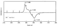
- FIG. 1 is a diagram showing a result of electron spin resonance (ESR) measurement in an example of the glass of the present invention.
- FIG. 2 is a graph showing the temperature change of the thermal expansion coefficient in the glasses of Examples 1 to 5 of the present invention.
- TiO 2 —SiO 2 glass is known to change its thermal expansion coefficient depending on the concentration of TiO 2 contained, and the thermal expansion coefficient of silica glass containing about 7% by mass of TiO 2 becomes almost zero near room temperature. .
- the silica glass containing TiO 2 used for the optical member of the present invention is a silica glass containing 3 to 10% by mass of TiO 2 . This is because if the content of TiO 2 is less than 3% by mass, zero expansion may not occur, and if it exceeds 10% by mass, the thermal expansion coefficient may be negative.
- the TiO 2 concentration is more preferably 5 to 9% by mass, particularly preferably 6 to 8% by mass.
- the internal transmittance T 400 to 700 of the optical member of the present invention is 80% or more. If T 400-700 is less than 80%, visible light is easily absorbed, and it may be difficult to determine the presence or absence of internal defects such as bubbles or striae by inspection with a microscope or visual inspection. There is. In addition, in the case of a member that transmits visible light, the intensity of transmitted light is reduced by use, which may impair component characteristics. T 400 to 700 is preferably 85% or more, particularly preferably 90% or more.
- the internal transmittance per 1mm thick in a wavelength range of 300 ⁇ 700 nm (hereinafter, referred to as internal transmittance T 300 ⁇ 700) It preferably 70% or more, 75% or more Is more preferable, and 80% or more is particularly preferable.
- the internal transmittance T 300 to 3000 of the optical member of the present invention is preferably 70% or more, and particularly preferably 80% or more. If T 300 to 3000 is less than 70%, it may be difficult to perform inspection for managing homogeneity and surface smoothness with a measuring instrument using a laser interferometer. . In addition, in the case of a member that transmits visible light or infrared light, the transmitted light intensity decreases, so that the characteristics of the component may be impaired. Since the optical member of the present invention contains TiO 2 , the absorption edge is in the vicinity of 250 nm. Therefore, KrF excimer laser (wavelength 248 nm) or ArF excimer laser (wavelength 193 nm) does not transmit light.
- the transmittance can be measured by using a spectrophotometer (U-3500 manufactured by Hitachi, Ltd.) with a mirror-polished glass having a thickness of 1 mm.
- the internal transmittance per 1 mm thickness is calculated by measuring the transmittance of samples with different thicknesses that have been mirror-polished to the same extent, for example, a 2 mm thick sample and a 1 mm thick sample, and the transmittance is measured as absorbance. After conversion, the absorbance per 1 mm is obtained by subtracting the absorbance of the 1 mm thick sample from the absorbance of the 2 mm thick sample, and converted to the transmittance again to obtain the internal transmittance per 1 mm thickness. Can do.
- the Ti 3+ concentration of the optical member of the present invention is 100 wtppm or less.
- the inventor has found that there is a relationship between Ti 3+ concentration and coloration, and in particular internal transmittance T 400-700 . Based on the results, brown coloration occurs when the Ti 3+ concentration exceeds 100 wtppm, and the internal transmittance T 400 to 700 is lowered, which may be insufficient for materials requiring transparency.
- the Ti 3+ concentration is preferably 70 wtppm or less, more preferably 50 wtppm or less, and particularly preferably 20 wtppm or less.
- Ti 3+ concentration was determined by ESR measurement. The measurement was performed under the following conditions. Frequency: Near 9.44 GHz (X-band) Output: 4mW Modulating magnetic field: 100 KHz, 0.2 mT Measurement temperature: Room temperature ESR species integration range: 332 to 368 mT Sensitivity calibration: Performed with a certain amount of Mn 2+ / MgO peak height.
- FIG. 1 An example of ESR measurement of TiO 2 —SiO 2 glass is shown in FIG.
- the vertical axis in FIG. 1 is the signal intensity, and the horizontal axis is the magnetic field intensity (mT).
- Ti 3+ in the glass, g 1.9 because it is observed before and after, they considered that the signal from Ti 3+, Ti 3+ concentration, the strength after twice integration of known concentration of the standard sample It was determined by comparing with the intensity after the corresponding two-time integration.
- the ratio ⁇ Ti 3+ / Ti 3+ of variation in Ti 3+ concentration to the average value of Ti 3+ concentration of the optical member of the present invention is 0.2 or less.
- ⁇ Ti 3+ / Ti 3+ exceeds 0.2, the distribution of characteristics such as coloring and absorption coefficient increases.
- ⁇ Ti 3+ / Ti 3+ is more preferably 0.15 or less, further preferably 0.1 or less, and particularly preferably 0.05 or less. If ⁇ Ti 3+ / Ti 3+ is 0.2 or less, the distribution of characteristics such as coloring and absorption coefficient distribution becomes small.
- ⁇ Ti 3+ / Ti 3+ is determined by the following method. Ti 3+ concentration is measured using the optical use surface of the optical member, and if it is formed, the film formation surface (hereinafter, the optical use surface of the optical member and the film formation surface when the film is formed are used optically) This is performed every 10 mm from end to end on an arbitrary line passing through the center point of the surface. The difference between the maximum and minimum values of Ti 3+ concentration of .DELTA.Ti 3+, seek ⁇ Ti 3+ / Ti 3+ by dividing by the average value of the Ti 3+ concentration.
- the thermal expansion coefficient (hereinafter referred to as CTE 0 to 100 ) at 0 to 100 ° C. of the optical member of the present invention is 0 ⁇ 150 ppb / ° C.
- CTE 0 to 100 is preferably 0 ⁇ 100 ppb / ° C., more preferably 0 ⁇ 75 ppb / ° C., particularly preferably 0 ⁇ 50 ppb / ° C.
- CTE ⁇ 50 to 150 is preferably 0 ⁇ 300 ppb / ° C., more preferably 0 ⁇ 250 ppb / ° C., and further preferably 0 ⁇ 200 ppb / ° C. 0 ⁇ 150 ppb / ° C. is particularly preferable.
- ⁇ COT The temperature distribution (hereinafter referred to as ⁇ COT) at which the thermal expansion coefficient of the optical member of the present invention becomes zero is preferably within 5 ° C.
- ⁇ COT is more preferably within 3 ° C., further preferably within 2 ° C., and particularly preferably within 1 ° C.
- an average coefficient of thermal expansion (hereinafter referred to as CTE 22 ) of glass at 22.0 ° C. is 0 ⁇ 30 ppb / ° C.
- CTE 22 is more preferably 0 ⁇ 20 ppb / ° C., further preferably 0 ⁇ 10 ppb / ° C., and particularly preferably 0 ⁇ 5 ppb / ° C.
- the temperature range where the coefficient of thermal expansion becomes 0 ⁇ 5 ppb / ° C. is increased by lowering the fictive temperature or containing F. Become.
- the temperature range where the thermal expansion coefficient is 0 ⁇ 5 ppb / ° C. is 4.0 ° C. or more. It is preferable that it is 4.5 degreeC or more.
- the thermal expansion coefficient can be measured in the range of ⁇ 150 to 200 ° C. using, for example, a laser interference type thermal dilatometer (a laser dilatometer LIX-1 manufactured by ULVAC Riko Co., Ltd.). In order to increase the measurement accuracy of the thermal expansion coefficient, it is effective to measure a plurality of times and average the thermal expansion coefficient.
- the temperature range in which the thermal expansion coefficient is 0 ⁇ 5 ppb / ° C. can be derived by obtaining the temperature range in which the thermal expansion coefficient is ⁇ 5 to 5 ppb / ° C. from the thermal expansion coefficient curve obtained by measurement.
- the distribution of thermal expansion coefficient is measured as follows. A glass in a region from the optical use surface of the optical member to a depth of about 2 mm is cut out, the thermal expansion coefficient is measured by the above method, and the temperature at which the thermal expansion coefficient becomes zero (hereinafter referred to as COT) is estimated. The coefficient of thermal expansion is measured every 20 mm from end to end on an arbitrary line passing through the center point of the optical surface. The difference between the maximum value and the minimum value of COT is defined as ⁇ COT.
- the OH group concentration of the optical member of the present invention is preferably 600 wtppm or less.
- the OH group concentration exceeds 600 wtppm, the light transmittance in the near-infrared wavelength band is lowered due to absorption caused by the OH group, and T 300 to 3000 may be 70% or less.
- the OH group concentration is more preferably 400 wtppm or less, further preferably 200 wtppm or less, and particularly preferably 100 wtppm or less. Most preferably, it is 30 ppm or less.
- OH group concentration is measured as follows. Measurement is performed with an infrared spectrophotometer, and the OH group concentration is determined from the absorption peak at a wavelength of 2.7 ⁇ m (JP Williams et. Al., Ceramic Bulletin, 55 (5), 524, 1976). The detection limit by this method is 0.1 wtppm.
- the fictive temperature of the optical member of the present invention is preferably 1100 ° C. or lower.
- the inventor has found that there is a relationship between the fictive temperature and the breadth of the zero expansion temperature range. Based on the result, when the fictive temperature exceeds 1100 ° C., the temperature range of zero expansion is narrow, which may be insufficient for the material used for the optical material of the exposure apparatus for EUVL.
- the fictive temperature is more preferably 1000 ° C. or lower, further preferably 900 ° C. or lower, and particularly preferably 850 ° C. or lower.
- a transparent glass body or a molded glass body which will be described later, is heated to a temperature of 1100 ° C. or higher, and the average temperature drop rate of 1100 to 800 ° C. is 10 ° C./hr or lower.
- a method of lowering the temperature is effective.
- the fictive temperature is measured as follows. With respect to the mirror-polished TiO 2 —SiO 2 glass, an absorption spectrum is obtained using an infrared spectrometer (Magna 760 manufactured by Nikolet). At this time, the data interval is set to about 0.5 cm ⁇ 1 , and the average value obtained by scanning 64 times is used as the absorption spectrum. In the infrared absorption spectrum thus obtained, the peak observed in the vicinity of about 2260 cm ⁇ 1 is due to the overtone of stretching vibration due to the Si—O—Si bond of the TiO 2 —SiO 2 glass. Using this peak position, a calibration curve is created with glass having the same fictive temperature and the same composition, and the fictive temperature is obtained.
- the TiO 2 —SiO 2 glass of the present invention can contain F (fluorine). It has been known for a long time that the F concentration affects the structural relaxation of glass (Journal of Applied Physics 91 (8), 4886 (2002)). It becomes easy to realize a low glass structure (first effect). Therefore, containing a large amount of F in the TiO 2 —SiO 2 glass has the effect of lowering the fictive temperature and expanding the temperature range of zero expansion due to the above-mentioned relevance.
- F fluorine
- F is considered to have the effect of extending the temperature range of zero expansion (second effect) more than expected by lowering the virtual temperature.
- the F concentration is preferably 1000 wtppm or more.
- the F concentration is more preferably 2000 wtppm or more, further preferably 3000 wtppm or more, and particularly preferably 4000 wtppm or more.
- the F concentration is preferably 100 wtppm or more, more preferably 200 wtppm or more, and even more preferably 500 wtppm or more.
- halogen other than F can reduce the temperature change of the thermal expansion coefficient in the temperature range of ⁇ 50 to 150 ° C. in the TiO 2 —SiO 2 glass like F, and the temperature range showing zero expansion can be reduced. It seems to have an effect of spreading.
- a porous TiO 2 —SiO 2 glass body is obtained by depositing and growing TiO 2 —SiO 2 glass fine particles (soot) obtained by flame hydrolysis or thermal decomposition of a Si precursor and a Ti precursor as glass forming raw materials. obtain.
- the obtained porous TiO 2 —SiO 2 glass body is treated in an F-containing atmosphere, and then heated to a temperature equal to or higher than the vitrification temperature to obtain a TiO 2 —SiO 2 glass body containing F.
- a Si precursor and a Ti precursor that are glass forming raw materials containing F are used, or the Si precursor and the Ti precursor are subjected to flame hydrolysis or thermal decomposition in an F-containing atmosphere to contain F.
- a porous TiO 2 —SiO 2 glass body is obtained and a TiO 2 —SiO 2 glass body containing F is obtained.
- Si precursors and Ti precursors containing F are used as glass forming raw materials, or Si precursors and Ti precursors are used in an oxyhydrogen flame at 1800 to 2000 ° C. in an F-containing atmosphere.
- Measured F concentration is as follows. The glass is heated and melted with anhydrous sodium carbonate, and distilled water and hydrochloric acid are added to the obtained melt at a volume ratio of 1 to the melt to adjust the sample solution. The electromotive force of the sample solution was used as an F-ion selective electrode and a reference electrode. 945-220 and no. 945-468, respectively, are measured with a radiometer, and the F content is obtained based on a calibration curve prepared in advance using an F ion standard solution (The Chemical Society of Japan, 1972 (2), 350). The detection limit by this method is 10 wtppm.
- the ratio ⁇ F / F of variation in F concentration with respect to the average value of F concentration is preferably 0.2 or less.
- F is contained, the production of Ti 3+ is promoted and coloration is facilitated.
- a distribution occurs in the F concentration, a distribution occurs in the Ti 3+ concentration. Therefore, when ⁇ F / F exceeds 0.2, the distribution of characteristics such as coloring and absorption coefficient becomes large. Further, the thermal expansion coefficient is distributed, and ⁇ COT may be increased.
- ⁇ F / F is more preferably 0.15 or less, further preferably 0.1 or less, and particularly preferably 0.05 or less.
- ⁇ F / F is measured according to the following procedure. 2 mm in depth from the optical use surface of the optical member, if formed, the film formation surface (hereinafter, the optical use surface of the optical member and the film formation surface in the case of film formation are collectively referred to as the optical use surface) The glass of the area
- the glass forming raw material is not particularly limited as long as it is a gasifiable raw material.
- the Si precursor include chlorides such as SiCl 4 , SiHCl 3 , SiH 2 Cl 2 and SiH 3 Cl, fluorides such as SiF 4 , SiHF 3 and SiH 2 F 2 , bromides such as SiBr 4 and SiHBr 3 , and SiI.
- Silicon halide compounds such as iodides such as 4, and R n Si (OR) 4-n (where R is an alkyl group having 1 to 4 carbon atoms, n is an integer of 0 to 3. And may be different from each other).
- Ti precursors include titanium halide compounds such as TiCl 4 and TiBr 4, and R n Ti (OR) 4-n (where R is an alkyl group having 1 to 4 carbon atoms, and n is 0 to 3). An integer, and a plurality of R may be the same or different from each other.
- Si and Ti compounds such as silicon titanium double alkoxide can be used as the Si precursor and the Ti precursor.
- the Ti precursor is flame-hydrolyzed with, for example, an oxyhydrogen flame, and it has been found that ⁇ Ti 3+ / Ti 3+ changes depending on the gas conditions of the oxyhydrogen flame. This is due to the following mechanism.
- Si precursor or Ti precursor to produce TiO 2 -SiO 2 glass fine particles by oxyhydrogen flame direct oxidation by reaction with oxygen and hydrolysis by reaction of moisture caused by combustion of oxygen and hydrogen There is.
- the hydrolysis reaction is dominant in the Si precursor, for example, SiCl 4
- the direct oxidation reaction is dominant in the Ti precursor, for example, TiCl 4 .
- the value O 2 / H 2 obtained by dividing the flow rate of oxygen by the flow rate of hydrogen is preferably 0.51 or more, more preferably 0.55 or more, further preferably 0.60 or more, and particularly preferably 0.65 or more.
- the following steps can be inserted after the porous glass body forming step.
- step (B) F-containing step In a reaction vessel filled with the porous glass body obtained in the above-mentioned step (a) with fluorine alone (F 2 ) or a mixed gas obtained by diluting fluorine alone (F 2 ) with an inert gas. To obtain a porous glass body containing fluorine.
- fluorine alone (F 2 ) is used as a fluorine source for introducing fluorine into the porous glass body.
- fluorine compound gas such as SiF 4 has been used, but in this case, the present inventors have found that ⁇ F / F increases and ⁇ Ti 3+ / Ti 3+ tends to increase.
- the simple fluorine (F 2 ) may be used as an inert gas, that is, a mixed gas diluted with a gas inert to the reaction that occurs when fluorine is introduced into the porous glass body.
- the inert gas used for the mixed gas include nitrogen gas, and rare gases such as helium gas and argon gas.
- hydrogen fluoride may be generated by reacting with fluorine alone (F 2 ) when used as a mixed gas.
- the dew point of the inert gas is preferably ⁇ 10 ° C. or lower, more preferably ⁇ 40 ° C. or lower, and particularly preferably ⁇ 60 ° C. or lower.
- elemental fluorine (F 2) is preferably used as a mixed gas diluted with an inert gas, in particular elemental fluorine (F 2) with nitrogen gas It is preferable to use it as a diluted mixed gas.
- the concentration of the simple fluorine (F 2 ) is 100 molppm to 50 mol% from the viewpoint of ease of control of the reaction and an economical viewpoint. It is preferable that it is 1000 molppm to 20 mol%.
- the rate of introducing fluorine into the porous glass body may be slow, and the treatment time may be long. On the other hand, if it exceeds 50 mol%, the rate of introducing fluorine into the porous glass body becomes high, and the control of the reaction may be difficult.
- highly reactive fluorine (F 2 ) is suitable as a fluorine source when introducing fluorine into the porous glass body, and is a porous material containing 1000 ppm or more of fluorine at a low temperature of 200 ° C. or less. It is possible to obtain a glass body.
- the porous glass body has a structurally unstable portion in the Si—O bond in the SiO 2 skeleton constituting the porous glass body, and has an unstable functional group such as Si—OH. There are parts to have. Since these bonds promote the formation of Si—F bonds by contacting fluorine alone (F 2 ), which is more reactive than SiF 4 , 1000 ppm in the porous glass body at a low temperature of 200 ° C. or lower.
- the inventors of the present application control the Si—OH contained in the porous glass body to be treated, reduce the distribution of bulk density, and make the porous glass body contain fluorine alone (F 2 ). It is possible to reduce the amount of fluorine desorbed when a porous glass body into which fluorine has been introduced is made into a transparent vitreous by a method such as positively removing HF generated in the reaction field during treatment with I found.
- the porous glass body when held in a reaction tank filled with fluorine alone (F 2 ) or a mixed gas obtained by diluting fluorine alone (F 2 ) with an inert gas, it is generated in the reaction field. It is preferable to remove HF continuously or intermittently.
- a method for continuously removing HF by holding it in a reaction vessel containing solid metal fluoride, HF generated in the reaction field is adsorbed to the solid metal fluoride, or fluorine alone ( Examples thereof include a method of circulating a mixed gas obtained by diluting F 2 ) or simple fluorine (F 2 ) with an inert gas.
- the solid metal fluoride to be used is not particularly limited, but is preferably selected from the group consisting of alkali metal fluorides, alkaline earth metal fluorides and mixtures thereof, and sodium fluoride is particularly preferred.
- the shape of the solid metal fluoride is not particularly limited, and any shape suitable for placement in the reaction vessel can be selected.
- the temperature in the reaction vessel is not particularly limited.
- the adsorption ability of HF by the solid metal fluoride is preferable because the lower the temperature in the reaction vessel, the better.
- the temperature in the reaction vessel is preferably 200 ° C. or lower, more preferably 150 ° C. or lower, and further preferably 100 ° C. or lower.
- the higher the temperature the easier the diffusion of fluorine into the porous glass body, and the higher the temperature in the reaction tank, the shorter the time for introducing fluorine into the porous glass body, which is preferable.
- the temperature in the reaction vessel is preferably ⁇ 50 ° C. or higher, more preferably 0 ° C. or higher, and further preferably 20 ° C. or higher.
- the pressure in the reaction vessel is not particularly limited. However, in order to efficiently adsorb HF, it is preferable to promote the diffusion of HF from the inside of the porous glass. From this viewpoint, the lower the pressure in the reaction vessel, the better.
- the pressure in the reaction vessel is preferably 1 MPa or less, more preferably 0.6 MPa or less, and further preferably 0.3 MPa or less in terms of gauge pressure.
- the pressure in the reaction vessel is preferably 0 MPa or more in terms of gauge pressure.
- the time for contacting the fluorine simple substance (F 2 ) with the porous glass body is preferably 1 minute to 1 week, particularly 10 minutes to 2 days.
- fluorine can be uniformly introduced into the porous glass body in a short time, so that the inside of the reaction vessel in which the porous glass body is disposed is under reduced pressure (preferably 13000 Pa).
- reduced pressure preferably 13000 Pa
- the degassing treatment is performed by placing the inside of the reaction vessel in which the porous glass body is disposed under reduced pressure, so that the moisture present in the reaction vessel Volatile organics can be removed. Thereby, it can prevent that a fluorine simple substance, these water
- the heating temperature is preferably 50 ° C to 300 ° C, more preferably 50 ° C to 200 ° C, and particularly preferably 50 ° C to 150 ° C.
- the steps (a) and (b) it is preferable to perform calcination between the steps (a) and (b) in order to increase the bulk density of the porous glass body.
- Si—OH is present on the surface of the particles at the stage of the porous glass body.
- the larger the bulk density the smaller the specific surface area of the particles, and the smaller the amount of Si—OH present in the porous glass body. That is, the larger the bulk density of the porous glass body, the smaller the amount of Si—OH present in the porous glass body, and when relatively contacting fluorine alone (F 2 ) with the porous glass body.
- the amount of HF to be generated becomes small.
- calcination When calcination is performed for such a purpose, it is preferably performed at a temperature of 1100 ° C. or higher. If it is less than 1100 ° C., the sintering of the particles does not proceed and the bulk density may not change. More preferably, it is 1150 degreeC or more.
- the calcination is preferably performed at a temperature of 1100 ° C. or more for 2 hours or more. More preferably, it is 3 hours or more, More preferably, it is 4 hours or more.
- the calcination is preferably performed at a temperature of 1350 ° C. or lower.
- the temperature exceeds 1350 ° C., sintering proceeds too much and closed pores exist, and therefore, when fluorine is introduced into the porous glass body in step (b), the fluorine concentration varies, or (d) step There is a risk that bubbles will remain after vitrification. More preferably, it is 1300 degrees C or less.
- the densification temperature refers to a temperature at which the porous glass body can be densified until voids cannot be confirmed with an optical microscope.
- the densification temperature is preferably 1100 to 1750 ° C, more preferably 1200 to 1550 ° C.
- the atmosphere is preferably an atmosphere of 100% inert gas such as helium or an atmosphere containing an inert gas such as helium as a main component at normal pressure. In the case of decompression, it is not particularly limited.
- the TiO 2 —SiO 2 dense body obtained in the densification step is heated to the vitrification temperature to obtain a transparent glass body substantially free of crystal components.
- the vitrification temperature is preferably 1400 to 1750 ° C., more preferably 1500 to 1700 ° C.
- the atmosphere is not particularly limited, but the same atmosphere as in the densification step, that is, an atmosphere containing 100% of an inert gas such as helium, or an atmosphere containing an inert gas such as helium as a main component at normal pressure is preferable. In the case of reduced pressure, the densification step and the vitrification step can be performed simultaneously.
- step (E) Molding step The transparent glass body obtained in the step (d) is heated to a temperature equal to or higher than the softening point and molded into a desired shape to obtain a molded glass body.
- the molding temperature is preferably 1500 to 1800 ° C. Above 1500 ° C., the viscosity is sufficiently lowered to such an extent that the transparent TiO 2 —SiO 2 glass is substantially self-weight deformed. Further, the growth of cristobalite, which is a crystal phase of SiO 2 , or the growth of rutile or anatase, which is a crystal phase of TiO 2 , hardly occurs, and so-called devitrification can be prevented. In addition, sublimation of SiO 2 can be suppressed at 1800 ° C. or lower. Note that the step (d) and the step (e) can be performed continuously or simultaneously.
- the TiO 2 —SiO 2 dense body obtained in the densification step can be omitted by performing the molding step without performing the vitrification step. That is, vitrification and molding can be performed simultaneously in the molding process.
- the atmosphere is not particularly limited.
- (F) Annealing step After heating the transparent glass body obtained in the step (d) or the molded glass body obtained in the step (e) to a temperature of 1100 ° C. or higher, an average temperature decreasing rate of 10 ° C./hr or lower.
- An annealing process for lowering the temperature to 500 ° C. or lower is performed to control the fictive temperature of the glass.
- the temperature of the obtained transparent glass body or molded glass body is decreased from 1200 ° C. to 500 ° C.
- the average temperature drop rate of 1100 to 800 ° C. is preferably 10 ° C./hr or less, more preferably 5 ° C./hr or less, particularly preferably 3 ° C./hr or less, and 1 ° C./hr. Most preferably:
- the obtained porous TiO 2 —SiO 2 glass body is difficult to handle as it is, it is kept in the atmosphere at 1200 ° C. for 4 hours and then removed from the substrate (temporary). Baking process).
- step (c) a dense TiO 2 —SiO 2
- the obtained TiO 2 —SiO 2 dense body was kept at 1680 ° C. for 4 hours to obtain a transparent glass body (step (d)).
- the obtained transparent glass body was put in a carbon mold and heated to 1700 ° C. to form a block shape, thereby obtaining a molded glass body (step (e)).
- the obtained molded glass body was held at 1100 ° C. for 5 hours, then cooled to 900 ° C. at 1 ° C./hr, further cooled to 500 ° C. at 5 ° C./hr, and then allowed to cool to room temperature. (Step (f)).
- the obtained porous TiO 2 —SiO 2 glass body is difficult to handle as it is, it is kept in the atmosphere at 1200 ° C. for 4 hours and then removed from the substrate (temporary). Baking process).
- the obtained porous TiO 2 —SiO 2 glass body was supported on a PFA jig, and placed in a nickel autoclave (A / C) together with the jig.
- NaF pellets manufactured by Stella Chemifa
- vacuum deaeration was performed until the pressure inside the apparatus became 266 Pa or lower in absolute pressure, and the system was held for 1 hour.
- step (c) F-containing TiO 2 —SiO 2 dense body
- the obtained F-containing TiO 2 —SiO 2 dense body was kept at 1680 ° C. for 4 hours to obtain a transparent glass body (step (d)).
- the obtained transparent glass body was put in a carbon mold and heated to 1700 ° C. to form a block shape, thereby obtaining a molded glass body (step (e)).
- the obtained molded glass body was heated to 1200 ° C., then cooled from 1200 ° C. to 500 ° C. at 5 ° C./hr, and then allowed to cool to room temperature. (Step (f)).
- the obtained porous TiO 2 —SiO 2 glass body is difficult to handle as it is, it is kept in the atmosphere at 1200 ° C. for 4 hours and then removed from the substrate (temporary). Baking process).
- step (c) a dense TiO 2 —SiO 2
- the obtained TiO 2 —SiO 2 dense body was kept at 1680 ° C. for 4 hours to obtain a transparent glass body (step (d)).
- the obtained transparent glass body was put in a carbon mold and heated to 1700 ° C. to form a block shape, thereby obtaining a molded glass body (step (e)).
- the obtained molded glass body was allowed to cool in the furnace as it was and allowed to cool to room temperature. At that time, the average temperature decrease rate from 1200 ° C. to 500 ° C. was 160 ° C./hr (step (f)).
- the obtained porous TiO 2 —SiO 2 glass body is difficult to handle as it is, it is kept in the atmosphere at 1200 ° C. for 4 hours and then removed from the substrate (temporary). Baking process).
- the temperature was raised to 1050 ° C. in an O 2 100% atmosphere, and held at normal pressure for 30 hours (oxygen treatment step).
- step (c) a TiO 2 —SiO 2 dense body containing F
- the obtained F-containing TiO 2 —SiO 2 dense body was kept in the atmosphere at 1650 ° C. for 4 hours to obtain a transparent glass body (step (d)).
- the obtained transparent glass body was put in a carbon mold and heated to 1650 ° C. to form a block shape, thereby obtaining a molded glass body (step (e)).
- the obtained molded glass body was heated to 1200 ° C., then cooled from 1200 ° C. to 500 ° C. at 5 ° C./hr, and then allowed to cool to room temperature. (Step (f)).
- porous TiO 2 —SiO 2 glass body Since the obtained porous TiO 2 —SiO 2 glass body is difficult to handle as it is, it is kept in the atmosphere at 1200 ° C. for 4 hours while being deposited on the substrate, then removed from the substrate, and has a diameter of about A porous TiO 2 —SiO 2 glass body having a length of 200 mm and a length of about 300 mm was obtained (calcination step).
- step (c) F-containing TiO 2 —SiO 2 dense body
- the obtained F-containing TiO 2 —SiO 2 dense body was kept at 1680 ° C. for 4 hours to obtain a transparent glass body (step (d)).
- the obtained transparent glass body is put in a carbon mold and heated to 1700 ° C. to be formed into a block shape to form a molded glass body (step (e)), and then cooled to 1000 ° C. at 10 ° C./hr in the furnace as it is. , Held at 1000 ° C. for 3 hours, cooled to 950 ° C. at 10 ° C./hr, held at 950 ° C. for 72 hours, cooled to 900 ° C. at 5 ° C./hr, held at 900 ° C. for 72 hours, then 500 ° C. Until the average temperature decreasing rate was 50 ° C./hr, and then allowed to cool to room temperature. Therefore, the average cooling rate from 1200 ° C. to 500 ° C. was 3.68 ° C./hr. (Step (f)).
- the glass body produced in Examples 1 to 5 above was cut into a plate shape of about 153.0 mm in length, about 153.0 mm in width, and about 6.75 mm in thickness using an inner peripheral slicer to produce 40 plate materials. To do. Next, a # 120 diamond grindstone is used with a commercially available NC chamfering machine, and these are chamfered so that the vertical and horizontal outer dimensions are about 152 mm and the chamfer width is 0.2 to 0.4 mm.
- a slurry obtained by suspending 18 to 20% by mass of GC # 400 (trade name, manufactured by Fujimi Corporation) substantially consisting of SiC in filtered water is used as an abrasive.
- the main surface of the plate (the surface on which the multilayer film or the absorption layer is formed) is polished until the thickness becomes about 6.63 mm.
- 20B double-sided polisher is used as the primary polish
- LP66 made of urethane (trade name, manufactured by Rhodes) is used as the polishing cloth
- Mille 801A (manufactured by Mitsui Kinzoku Co., Ltd.) mainly containing cerium oxide as the polishing agent. Polish about 50 ⁇ m on both sides using a slurry in which 10 to 12% by mass of (trade name) is suspended.
- polishing (tertiary polish) is performed.
- colloidal silica (Compole 20: trade name, manufactured by Fujimi Corporation) is used as an abrasive
- Bellatrix K7512 (trade name, manufactured by Kanebo) is used as an abrasive cloth.
- these substrates are washed with a multi-stage automatic washing machine in which the first tank is a hot solution of sulfuric acid and hydrogen peroxide and the third tank is a neutral surfactant solution.
- FIG. 2 shows the temperature change of the thermal expansion coefficient of the glass prepared in Examples 1 to 5 above.
- the thermal expansion coefficient of the glass was measured using a laser interference thermal expansion system (a laser dilatometer LIX-1 manufactured by ULVAC Riko Co., Ltd.).
- Tables 1 and 2 show the measurement results of the physical properties of the glass substrates produced in Examples 1 to 5 above.
- the evaluation method it performed according to the above-mentioned measuring method, respectively.
- the temperature range in which the thermal expansion coefficient in Table 2 is 0 ⁇ 5 ppb / ° C. was derived by obtaining the temperature range in which the thermal expansion coefficient is ⁇ 5 to 5 ppb / ° C. from the curve in FIG.
- Examples 1, 2, and 5 are examples
- Examples 3 and 4 are comparative examples.
- Example 1 is a TiO 2 —SiO 2 glass having a Ti 3+ concentration of 100 wtppm or less, a coefficient of thermal expansion CTE 0-100 at 0-100 ° C. of 0 ⁇ 150 ppb / ° C., and a thickness in the wavelength range of 400-700 nm.
- the internal transmittance T 400 to 700 per mm was 80% or more, and the ratio ⁇ Ti 3+ / Ti 3+ of variation in Ti 3+ concentration to the average value of Ti 3+ concentration was 0.2 or less.
- Example 2 is a TiO 2 —SiO 2 glass containing F, with a Ti 3+ concentration of 100 wtppm or less, a coefficient of thermal expansion CTE of 0 to 100 ° C. at 0 to 100 ° C. 0 to 150 ppb / ° C., and 400 to 700 nm.
- the internal transmittance T 400 to 700 per 1 mm thickness was 80% or more, and the ratio ⁇ Ti 3+ / Ti 3+ of the variation of Ti 3+ concentration to the average value of Ti 3+ concentration was 0.2 or less.
- the F concentration is 1000 wtppm or more, and the ratio ⁇ F / F of the variation of the F concentration with respect to the average value of the F concentration is 0.2 or less.
- Example 3 is a TiO 2 -SiO 2 glass, the proportion of the variation of the Ti 3+ concentration to the average value of the Ti 3+ concentration ⁇ Ti 3+ / Ti 3+ 0.2 super, and the distribution in the coloration was observed.
- Example 4 is a TiO 2 —SiO 2 glass containing F, but the ratio of variation in Ti 3+ concentration to the average value of Ti 3+ concentration ⁇ Ti 3+ / Ti 3+ exceeds 0.2, and distribution is seen in coloring. .
- Example 5 is a TiO 2 —SiO 2 glass containing F, the Ti 3+ concentration is 100 wtppm or less, the thermal expansion coefficient CTE at 0 to 100 ° C. 0 to 100 is 0 ⁇ 150 ppb / ° C., and 400 to 700 nm.
- the internal transmittance T 400 to 700 per 1 mm thickness was 80% or more, and the ratio ⁇ Ti 3+ / Ti 3+ of the variation of Ti 3+ concentration to the average value of Ti 3+ concentration was 0.2 or less.
- the F concentration is 1000 wtppm or more, and the ratio ⁇ F / F of the variation of the F concentration with respect to the average value of the F concentration is 0.2 or less.
- the temperature width at which the thermal expansion coefficient becomes 0 ⁇ 5 ppb / ° C. is 4.0 ° C. or more.
- the glass substrates of Examples 1, 2 and 5 can acquire data over the entire measurement region. In the glass substrate of Example 4, some data is generated, and the entire area cannot be measured.
- the optical member of the present invention has a wide temperature range where the thermal expansion coefficient is almost zero, excellent transparency, and a small distribution of characteristics such as coloring and absorption coefficient, and as an optical member constituting an optical system used in EUVL. It can be used very suitably. Moreover, the optical member of the present invention can be suitably used as a base material constituting a nanoimprint mold.
Abstract
Description
これに対し、透明性に優れ、かつ広い温度範囲において熱膨張係数がほぼゼロとなるTiO2を含有するシリカガラスとその製造方法が開示されている(例えば、特許文献2参照。)。また、より広い温度領域でゼロ膨張特性を有するFを含有したTiO2-SiO2ガラスとその製造方法が開示されている(例えば、特許文献3参照。)。 In addition, optical component materials, precision component materials such as precision measuring standards and various electronic materials, and EUVL exposure apparatus optical members preferably have a wide temperature range in which the thermal expansion coefficient is substantially zero. In the TiO 2 —SiO 2 glass, the temperature range where the thermal expansion coefficient is almost zero is limited only to around room temperature. Further, the conventional crystallized glass has a problem in absolute dimensional accuracy because a dimensional change with respect to a temperature change shows hysteresis due to structural relaxation, and a problem that a smooth surface is difficult to obtain.
On the other hand, silica glass containing TiO 2 having excellent transparency and having a thermal expansion coefficient of almost zero in a wide temperature range and a method for producing the same are disclosed (for example, see Patent Document 2). Further, a TiO 2 —SiO 2 glass containing F having zero expansion characteristics in a wider temperature range and a method for producing the same are disclosed (for example, see Patent Document 3).
ガラス形成原料を火炎加水分解して得られる石英ガラス微粒子を基材に堆積、成長させて多孔質ガラス体を形成する工程と、
前記多孔質ガラス体を、フッ素単体(F2)またはフッ素単体(F2)を不活性ガスで希釈した混合ガスで満たされた反応槽内に保持することにより、フッ素を含有した多孔質ガラス体を得る工程と、
前記フッ素を含有した多孔質ガラス体を、透明ガラス化温度まで昇温して、フッ素を含有した透明ガラス体を得る工程と、
を含む、TiO2を含有するシリカガラスからなる光学部材の製造方法を提供する。 Embodiment 8, the ratio of the variation of the Ti 3+ concentration to the average value of the Ti 3+ concentration in the optical working surfaces ΔTi 3+ / Ti 3+ is 0.2 or less, contains F, F concentration is more than 1000 wtppm, TiO 2 A method for producing an optical member made of silica glass containing
A step of depositing and growing quartz glass fine particles obtained by flame hydrolysis of a glass forming raw material on a base material to form a porous glass body;
A porous glass body containing fluorine by holding the porous glass body in a reaction tank filled with fluorine alone (F 2 ) or a mixed gas obtained by diluting fluorine alone (F 2 ) with an inert gas. Obtaining
Heating the porous glass body containing fluorine to a transparent vitrification temperature to obtain a transparent glass body containing fluorine; and
Including, to provide a process for producing an optical member comprising silica glass containing TiO 2.
また、低熱膨張性および透明性が厳しく要求される各種材料、例えば光学部品材料、大型反射鏡基板材料、精密測定用基準器等の精密部品材料および各種電子材料等に用いられる透明超低膨張ガラスとして好適である。 According to the present invention, it is possible to obtain an optical member made of a transparent ultra-low thermal expansion glass having a wide temperature range where the thermal expansion coefficient is almost zero, excellent transparency, and small distribution of characteristics such as coloring and absorption coefficient. Therefore, it is very suitable as an optical member constituting an optical system used for EUVL.
Transparent ultra-low expansion glass used for various materials that are strictly required to have low thermal expansibility and transparency, such as optical component materials, large reflector substrate materials, precision component materials such as precision measuring standards, and various electronic materials. It is suitable as.
周波数 :9.44GHz付近(X-band)
出力 :4mW
変調磁場 :100KHz、0.2mT
測定温度 :室温
ESR種積分範囲:332~368mT
感度校正 :一定量のMn2+/MgOのピーク高さにて実施。 Ti 3+ concentration was determined by ESR measurement. The measurement was performed under the following conditions.
Frequency: Near 9.44 GHz (X-band)
Output: 4mW
Modulating magnetic field: 100 KHz, 0.2 mT
Measurement temperature: Room temperature ESR species integration range: 332 to 368 mT
Sensitivity calibration: Performed with a certain amount of Mn 2+ / MgO peak height.
Ti3+濃度の測定は、光学部材の光学使用面、成膜されている場合はその成膜面(以下、光学部材の光学使用面と成膜されている場合の成膜面をあわせて光学使用面という)の中心点を通る任意のライン上で端から端まで10mmおきに行う。Ti3+濃度の最大値と最小値の差をΔTi3+とし、Ti3+濃度の平均値で除することでΔTi3+/Ti3+を求める。 ΔTi 3+ / Ti 3+ is determined by the following method.
Ti 3+ concentration is measured using the optical use surface of the optical member, and if it is formed, the film formation surface (hereinafter, the optical use surface of the optical member and the film formation surface when the film is formed are used optically) This is performed every 10 mm from end to end on an arbitrary line passing through the center point of the surface. The difference between the maximum and minimum values of Ti 3+ concentration of .DELTA.Ti 3+, seek ΔTi 3+ / Ti 3+ by dividing by the average value of the Ti 3+ concentration.
(a)多孔質ガラス体形成工程
ガラス形成原料であるSi前駆体およびTi前駆体を火炎加水分解させて得られるTiO2-SiO2ガラス微粒子を基材に堆積、成長させて多孔質TiO2-SiO2ガラス体を形成させる。ガラス形成原料としては、ガス化可能な原料であれば特に限定されない。Si前駆体としては、SiCl4、SiHCl3、SiH2Cl2、SiH3Clなどの塩化物、SiF4、SiHF3、SiH2F2などのフッ化物、SiBr4、SiHBr3などの臭化物、SiI4などのヨウ化物といったハロゲン化ケイ素化合物、またRnSi(OR)4-n(ここにRは炭素数1~4のアルキル基、nは0~3の整数。複数のRは互いに同一でも異なっていてもよい。)で示されるアルコキシシランが挙げられる。また、Ti前駆体としては、TiCl4、TiBr4などのハロゲン化チタン化合物、またRnTi(OR)4-n(ここにRは炭素数1~4のアルキル基、nは0~3の整数。複数のRは互いに同一でも異なっていてもよい。)で示されるアルコキシチタンが挙げられる。また、Si前駆体およびTi前駆体として、シリコンチタンダブルアルコキシドなどのSiとTiの化合物を使用することもできる。 In order to produce the glass of the present invention, the following production method can be employed.
(A) Porous glass body forming step TiO 2 —SiO 2 glass fine particles obtained by flame hydrolysis of Si precursor and Ti precursor, which are glass forming raw materials, are deposited and grown on a substrate to form porous TiO 2 —. to form a SiO 2 glass body. The glass forming raw material is not particularly limited as long as it is a gasifiable raw material. Examples of the Si precursor include chlorides such as SiCl 4 , SiHCl 3 , SiH 2 Cl 2 and SiH 3 Cl, fluorides such as SiF 4 , SiHF 3 and SiH 2 F 2 , bromides such as SiBr 4 and SiHBr 3 , and SiI. Silicon halide compounds such as iodides such as 4, and R n Si (OR) 4-n (where R is an alkyl group having 1 to 4 carbon atoms, n is an integer of 0 to 3. And may be different from each other). Ti precursors include titanium halide compounds such as TiCl 4 and TiBr 4, and R n Ti (OR) 4-n (where R is an alkyl group having 1 to 4 carbon atoms, and n is 0 to 3). An integer, and a plurality of R may be the same or different from each other. In addition, Si and Ti compounds such as silicon titanium double alkoxide can be used as the Si precursor and the Ti precursor.
上記(a)工程で得られた多孔質ガラス体を、フッ素単体(F2)またはフッ素単体(F2)を不活性ガスで希釈した混合ガスで満たされた反応槽内に保持し、フッ素を含有した多孔質ガラス体を得る。 (B) F-containing step In a reaction vessel filled with the porous glass body obtained in the above-mentioned step (a) with fluorine alone (F 2 ) or a mixed gas obtained by diluting fluorine alone (F 2 ) with an inert gas. To obtain a porous glass body containing fluorine.
なお、反応の制御のしやすさ、および経済的な観点から、フッ素単体(F2)は不活性ガスで希釈した混合ガスとして使用することが好ましく、特にフッ素単体(F2)を窒素ガスで希釈した混合ガスとして使用することが好ましい。
なお、フッ素単体(F2)を窒素ガスで希釈した混合ガスとして使用する場合、反応の制御のしやすさ、および経済的な観点から、フッ素単体(F2)の濃度が100molppm~50mol%であることが好ましく、1000molppm~20mol%であることがより好ましい。フッ素単体(F2)の濃度が100molppm未満であると、多孔質ガラス体にフッ素を導入する速度が遅くなり処理時間が長くなるおそれがある。一方で50mol%を越えると、多孔質ガラス体にフッ素を導入する速度が速くなり反応の制御が困難となるおそれがある。 Specific examples of the inert gas used for the mixed gas include nitrogen gas, and rare gases such as helium gas and argon gas. However, it should be noted that if moisture is contained in the inert gas, hydrogen fluoride may be generated by reacting with fluorine alone (F 2 ) when used as a mixed gas. In this respect, the dew point of the inert gas is preferably −10 ° C. or lower, more preferably −40 ° C. or lower, and particularly preferably −60 ° C. or lower.
Incidentally, ease of control of the reaction, and from an economic point of view, elemental fluorine (F 2) is preferably used as a mixed gas diluted with an inert gas, in particular elemental fluorine (F 2) with nitrogen gas It is preferable to use it as a diluted mixed gas.
In the case of using simple fluorine (F 2 ) as a mixed gas diluted with nitrogen gas, the concentration of the simple fluorine (F 2 ) is 100 molppm to 50 mol% from the viewpoint of ease of control of the reaction and an economical viewpoint. It is preferable that it is 1000 molppm to 20 mol%. When the concentration of the fluorine simple substance (F 2 ) is less than 100 molppm, the rate of introducing fluorine into the porous glass body may be slow, and the treatment time may be long. On the other hand, if it exceeds 50 mol%, the rate of introducing fluorine into the porous glass body becomes high, and the control of the reaction may be difficult.
しかしながら、フッ素源としてフッ素単体(F2)を使用した場合、続けて実施する多孔質ガラス体を緻密体とするための加熱処理により、フッ素が離脱して、得られる透明ガラス体中のフッ素濃度が低下、また、フッ素濃度分布を悪化させる不純物として混入する水分や揮発性有機物などはフッ素単体(F2)と反応してHFを生成し、多孔質ガラス体のSi-O-Siの骨格と反応して、Si-Fを形成するとともに、プロトン源であるSi-OHを新たに形成する可能性がある。こうして形成されるSi-OHは、多孔質ガラス体を透明ガラス化させる際に、以下の反応によってフッ素の脱離を引き起こすという問題がある。これにより、ΔF/Fが大きくなり、ΔTi3+/Ti3+が大きくなる可能性がある。
Si-OH+Si-F → Si-O-Si + HF↑
Si-O-Si-F3 + HF → Si-OH + SiF4↑
以上の点から、本願発明者らは、処理する多孔質ガラス体に含まれるSi-OHを制御する、嵩密度の分布を低減する、多孔質ガラス体をフッ素単体(F2)を含有する雰囲気にて処理する際に反応場内で生じるHFを積極的に除去する、などの方法により、フッ素を導入した多孔質ガラス体を透明ガラス化させる際に脱離するフッ素の量を低減することができることを見出した。 As described above, highly reactive fluorine (F 2 ) is suitable as a fluorine source when introducing fluorine into the porous glass body, and is a porous material containing 1000 ppm or more of fluorine at a low temperature of 200 ° C. or less. It is possible to obtain a glass body. The porous glass body has a structurally unstable portion in the Si—O bond in the SiO 2 skeleton constituting the porous glass body, and has an unstable functional group such as Si—OH. There are parts to have. Since these bonds promote the formation of Si—F bonds by contacting fluorine alone (F 2 ), which is more reactive than SiF 4 , 1000 ppm in the porous glass body at a low temperature of 200 ° C. or lower. It is possible to introduce the above fluorine.
However, when fluorine alone (F 2 ) is used as the fluorine source, the fluorine is released by the heat treatment to make the porous glass body to be a dense body, and the fluorine concentration in the transparent glass body to be obtained In addition, moisture and volatile organic substances mixed as impurities that deteriorate the fluorine concentration distribution react with fluorine alone (F 2 ) to generate HF, and the Si—O—Si skeleton of the porous glass body It reacts to form Si—F, and there is a possibility that Si—OH as a proton source is newly formed. The Si—OH formed in this way has a problem of causing fluorine elimination by the following reaction when the porous glass body is made into a transparent glass. As a result, ΔF / F increases and ΔTi 3+ / Ti 3+ may increase.
Si-OH + Si-F → Si-O-Si + HF ↑
Si-O-Si-F 3 + HF → Si-OH + SiF 4 ↑
In view of the above, the inventors of the present application control the Si—OH contained in the porous glass body to be treated, reduce the distribution of bulk density, and make the porous glass body contain fluorine alone (F 2 ). It is possible to reduce the amount of fluorine desorbed when a porous glass body into which fluorine has been introduced is made into a transparent vitreous by a method such as positively removing HF generated in the reaction field during treatment with I found.
使用する固体金属フッ化物は特に限定されないが、アルカリ金属のフッ化物、アルカリ土類金属のフッ化物およびこれらの混合物からなる群より選ばれたものが好ましく、その中でもフッ化ナトリウムがとりわけ好ましい。固体金属フッ化物の形状は特に限定されず、反応槽内に配置するのに適した任意の形状を選択することができる。 In the step (b), when the porous glass body is held in a reaction tank filled with fluorine alone (F 2 ) or a mixed gas obtained by diluting fluorine alone (F 2 ) with an inert gas, it is generated in the reaction field. It is preferable to remove HF continuously or intermittently. As a method for continuously removing HF, by holding it in a reaction vessel containing solid metal fluoride, HF generated in the reaction field is adsorbed to the solid metal fluoride, or fluorine alone ( Examples thereof include a method of circulating a mixed gas obtained by diluting F 2 ) or simple fluorine (F 2 ) with an inert gas. In addition, if necessary, supply or discharge of fluorine alone (F 2 ) or mixed gas obtained by diluting fluorine alone (F 2 ) with inert gas, or both are temporarily stopped. Therefore, HF can be intermittently removed. As a result, new generation of Si—OH in the porous glass body can be suppressed, and the proton source inside the porous glass body can be reduced. As a result, when the porous glass body is made into a transparent vitreous in the subsequent step (c), it is possible to prevent the fluorine introduced into the porous glass body in this step from being detached.
The solid metal fluoride to be used is not particularly limited, but is preferably selected from the group consisting of alkali metal fluorides, alkaline earth metal fluorides and mixtures thereof, and sodium fluoride is particularly preferred. The shape of the solid metal fluoride is not particularly limited, and any shape suitable for placement in the reaction vessel can be selected.
一方で、反応槽内が減圧になると、反応槽内に外気が吸引される可能性がある。外気中に含まれる水分や揮発性有機物などはフッ素単体(F2)と反応してHFを生成するため、外気の吸引は避ける方が好ましい。この観点から、反応槽内の圧力はゲージ圧で0MPa以上が好ましい。 In the step (b), the pressure in the reaction vessel is not particularly limited. However, in order to efficiently adsorb HF, it is preferable to promote the diffusion of HF from the inside of the porous glass. From this viewpoint, the lower the pressure in the reaction vessel, the better. The pressure in the reaction vessel is preferably 1 MPa or less, more preferably 0.6 MPa or less, and further preferably 0.3 MPa or less in terms of gauge pressure.
On the other hand, when the pressure in the reaction tank is reduced, outside air may be sucked into the reaction tank. Since moisture, volatile organic substances, etc. contained in the outside air react with fluorine alone (F 2 ) to generate HF, it is preferable to avoid sucking outside air. From this viewpoint, the pressure in the reaction vessel is preferably 0 MPa or more in terms of gauge pressure.
多孔質ガラス体の段階では、粒子の表面にSi-OHが存在していると考えられる。嵩密度が大きいほど、粒子の比表面積が小さくなり、相対的に多孔質ガラス体に存在するSi-OHの量が少なくなると考えられる。すなわち、多孔質ガラス体の嵩密度が大きいほど、該多孔質ガラス体に存在するSi-OHの量が少なくなり、相対的に多孔質ガラス体にフッ素単体(F2)を接触させた際に生成するHFの量が小さくなると考えられる。結果として次に実施する(d)工程でのフッ素の脱離を抑制することができ、ΔF/Fを小さくして、ΔTi3+/Ti3+を小さくすることが可能となる。 Furthermore, it is preferable to perform calcination between the steps (a) and (b) in order to increase the bulk density of the porous glass body.
It is considered that Si—OH is present on the surface of the particles at the stage of the porous glass body. It is considered that the larger the bulk density, the smaller the specific surface area of the particles, and the smaller the amount of Si—OH present in the porous glass body. That is, the larger the bulk density of the porous glass body, the smaller the amount of Si—OH present in the porous glass body, and when relatively contacting fluorine alone (F 2 ) with the porous glass body. It is considered that the amount of HF to be generated becomes small. As a result, it is possible to suppress the desorption of fluorine in the step (d) to be performed next, and ΔF / F can be reduced and ΔTi 3+ / Ti 3+ can be reduced.
仮焼は、1100℃以上の温度で2時間以上実施することが好ましい。より好ましくは3時間以上、さらに好ましくは4時間以上である。 When calcination is performed for such a purpose, it is preferably performed at a temperature of 1100 ° C. or higher. If it is less than 1100 ° C., the sintering of the particles does not proceed and the bulk density may not change. More preferably, it is 1150 degreeC or more.
The calcination is preferably performed at a temperature of 1100 ° C. or more for 2 hours or more. More preferably, it is 3 hours or more, More preferably, it is 4 hours or more.
上記(a)工程で得られた多孔質ガラス体、あるいは(b)工程で得られたフッ素を含有した多孔質ガラス体を、緻密化温度まで昇温して、実質的に泡や気泡を含有しないTiO2-SiO2緻密体を得る。本明細書では、緻密化温度とは、光学顕微鏡で空隙が確認できなくなるまで多孔質ガラス体を緻密化できる温度をいう。緻密化温度は、1100~1750℃であることが好ましく、より好ましくは1200~1550℃である。 (C) Densification step The porous glass body obtained in the step (a) or the porous glass body containing fluorine obtained in the step (b) is heated to the densification temperature, and substantially Thus, a dense TiO 2 —SiO 2 body containing no bubbles or bubbles is obtained. In the present specification, the densification temperature refers to a temperature at which the porous glass body can be densified until voids cannot be confirmed with an optical microscope. The densification temperature is preferably 1100 to 1750 ° C, more preferably 1200 to 1550 ° C.
緻密化工程で得られたTiO2-SiO2緻密体をガラス化温度まで昇温して、実質的に結晶成分を含有しない透明ガラス体を得る。ガラス化温度は、1400~1750℃であることが好ましく、より好ましくは1500~1700℃である。 (D) Vitrification step The TiO 2 —SiO 2 dense body obtained in the densification step is heated to the vitrification temperature to obtain a transparent glass body substantially free of crystal components. The vitrification temperature is preferably 1400 to 1750 ° C., more preferably 1500 to 1700 ° C.
(d)工程で得られた透明ガラス体を、軟化点以上の温度に加熱して所望の形状に成形し、成形ガラス体を得る。成形加工の温度としては、1500~1800℃が好ましい。
1500℃以上では、透明TiO2-SiO2ガラスが実質的に自重変形する位に十分粘性が下がる。またSiO2の結晶相であるクリストバライトの成長、または、TiO2の結晶相であるルチルもしくはアナターゼの成長が起こりにくく、いわゆる失透の発生を防止できる。また、1800℃以下では、SiO2の昇華が抑えられる。
なお、(d)工程と(e)工程を連続的に、あるいは同時に行うこともできる。 (E) Molding step The transparent glass body obtained in the step (d) is heated to a temperature equal to or higher than the softening point and molded into a desired shape to obtain a molded glass body. The molding temperature is preferably 1500 to 1800 ° C.
Above 1500 ° C., the viscosity is sufficiently lowered to such an extent that the transparent TiO 2 —SiO 2 glass is substantially self-weight deformed. Further, the growth of cristobalite, which is a crystal phase of SiO 2 , or the growth of rutile or anatase, which is a crystal phase of TiO 2 , hardly occurs, and so-called devitrification can be prevented. In addition, sublimation of SiO 2 can be suppressed at 1800 ° C. or lower.
Note that the step (d) and the step (e) can be performed continuously or simultaneously.
(d)工程で得られた透明ガラス体、あるいは(e)工程で得られた成形ガラス体を、1100℃以上の温度に加熱後、10℃/hr以下の平均降温速度で500℃以下の温度まで降温するアニール処理を行い、ガラスの仮想温度を制御する。あるいは、(d)工程や(e)工程における1200℃以上の温度からの降温過程において、得られる透明ガラス体や成形ガラス体を1200℃から500℃まで10℃/hr以下の平均降温速度で降温するアニール処理を行い、ガラスの仮想温度を制御する。さらに、1100~800℃の平均降温速度が10℃/hr以下であることが好ましく、5℃/hr以下であることがより好ましく、3℃/hr以下であることが特に好ましく、1℃/hr以下であることが最も好ましい。 (F) Annealing step After heating the transparent glass body obtained in the step (d) or the molded glass body obtained in the step (e) to a temperature of 1100 ° C. or higher, an average temperature decreasing rate of 10 ° C./hr or lower. An annealing process for lowering the temperature to 500 ° C. or lower is performed to control the fictive temperature of the glass. Alternatively, in the temperature lowering process from a temperature of 1200 ° C. or higher in the step (d) or the step (e), the temperature of the obtained transparent glass body or molded glass body is decreased from 1200 ° C. to 500 ° C. at an average temperature decreasing rate of 10 ° C./hr or lower An annealing process is performed to control the fictive temperature of the glass. Further, the average temperature drop rate of 1100 to 800 ° C. is preferably 10 ° C./hr or less, more preferably 5 ° C./hr or less, particularly preferably 3 ° C./hr or less, and 1 ° C./hr. Most preferably:
[例1]
TiO2-SiO2ガラスのガラス形成原料であるTiCl4とSiCl4を、それぞれガス化させた後に混合させ、酸水素火炎中で加熱加水分解(火炎加水分解)させることで得られるTiO2-SiO2ガラス微粒子を基材に堆積・成長させて、多孔質TiO2-SiO2ガラス体を形成した。このとき、酸素の流量と水素の流量の比は、O2/H2=0.68とした((a)工程)。 EXAMPLES Hereinafter, although an Example demonstrates this invention further in detail, this invention is not limited to this.
[Example 1]
TiCl 4 and SiCl 4 as glass-forming raw material for TiO 2 -SiO 2 glass, was mixed after each is gasified, TiO 2 -SiO to subjecting the mixture to heat hydrolysis in an oxyhydrogen flame (flame hydrolysis) Two glass particles were deposited and grown on a substrate to form a porous TiO 2 —SiO 2 glass body. At this time, the ratio of the flow rate of oxygen and the flow rate of hydrogen was set to O 2 / H 2 = 0.68 (step (a)).
TiO2-SiO2ガラスのガラス形成原料であるTiCl4とSiCl4を、それぞれガス化させた後に混合させ、酸水素火炎中で加熱加水分解(火炎加水分解)させることで得られるTiO2-SiO2ガラス微粒子を基材に堆積・成長させて、多孔質TiO2-SiO2ガラス体を形成した。このとき、酸素の流量と水素の流量の比は、O2/H2=0.56とした((a)工程)。 [Example 2]
TiCl 4 and SiCl 4 as glass-forming raw material for TiO 2 -SiO 2 glass, was mixed after each is gasified, TiO 2 -SiO to subjecting the mixture to heat hydrolysis in an oxyhydrogen flame (flame hydrolysis) Two glass particles were deposited and grown on a substrate to form a porous TiO 2 —SiO 2 glass body. At this time, the ratio between the flow rate of oxygen and the flow rate of hydrogen was set to O 2 / H 2 = 0.56 (step (a)).
次いで、装置内を80℃に保ったまま、装置内の圧力が絶対圧266Pa以下となるまで真空脱気し、1時間保持した。
次いで、窒素ガスで20体積%に希釈したフッ素単体(F2)のガスを、装置内の圧力をゲージ圧0.18MPaとなるまで導入し、80℃まで昇温した後、24時間保持することにより、多孔質TiO2-SiO2ガラス体にフッ素を導入した。((b)工程) The obtained porous TiO 2 —SiO 2 glass body was supported on a PFA jig, and placed in a nickel autoclave (A / C) together with the jig. Next, NaF pellets (manufactured by Stella Chemifa) were inserted into the autoclave so as not to contact the porous TiO 2 —SiO 2 glass body, and then heated from the outside of the autoclave using an oil bath and heated to 80 ° C.
Next, while the inside of the apparatus was kept at 80 ° C., vacuum deaeration was performed until the pressure inside the apparatus became 266 Pa or lower in absolute pressure, and the system was held for 1 hour.
Next, a simple fluorine (F 2 ) gas diluted to 20% by volume with nitrogen gas is introduced until the pressure in the apparatus reaches a gauge pressure of 0.18 MPa, the temperature is raised to 80 ° C., and then maintained for 24 hours. Thus, fluorine was introduced into the porous TiO 2 —SiO 2 glass body. ((B) Process)
TiO2-SiO2ガラスのガラス形成原料であるTiCl4とSiCl4を、それぞれガス化させた後に混合させ、酸水素火炎中で加熱加水分解(火炎加水分解)させることで得られるTiO2-SiO2ガラス微粒子を基材に堆積・成長させて、多孔質TiO2-SiO2ガラス体を形成した。このとき、酸素の流量と水素の流量の比は、O2/H2=0.50とした((a)工程)。 [Example 3]
TiCl 4 and SiCl 4 as glass-forming raw material for TiO 2 -SiO 2 glass, was mixed after each is gasified, TiO 2 -SiO to subjecting the mixture to heat hydrolysis in an oxyhydrogen flame (flame hydrolysis) Two glass particles were deposited and grown on a substrate to form a porous TiO 2 —SiO 2 glass body. At this time, the ratio of the flow rate of oxygen and the flow rate of hydrogen was set to O 2 / H 2 = 0.50 (step (a)).
TiO2-SiO2ガラスのガラス形成原料であるTiCl4とSiCl4を、それぞれガス化させた後に混合させ、酸水素火炎中で加熱加水分解(火炎加水分解)させることで得られるTiO2-SiO2ガラス微粒子を基材に堆積・成長させて、多孔質TiO2-SiO2ガラス体を形成した。このとき、酸素の流量と水素の流量の比は、O2/H2=0.56とした((a)工程)。 [Example 4]
TiCl 4 and SiCl 4 as glass-forming raw material for TiO 2 -SiO 2 glass, was mixed after each is gasified, TiO 2 -SiO to subjecting the mixture to heat hydrolysis in an oxyhydrogen flame (flame hydrolysis) Two glass particles were deposited and grown on a substrate to form a porous TiO 2 —SiO 2 glass body. At this time, the ratio between the flow rate of oxygen and the flow rate of hydrogen was set to O 2 / H 2 = 0.56 (step (a)).
TiO2-SiO2ガラスのガラス形成原料であるTiCl4とSiCl4を、それぞれガス化させた後に混合させ、酸水素火炎中で加熱加水分解(火炎加水分解)させることで得られるTiO2-SiO2ガラス微粒子を基材に堆積・成長させて、多孔質TiO2-SiO2ガラス体を形成した。このとき、酸素の流量と水素の流量の比は、O2/H2=0.76とした((a)工程)。 [Example 5]
TiCl 4 and SiCl 4 as glass-forming raw material for TiO 2 -SiO 2 glass, was mixed after each is gasified, TiO 2 -SiO to subjecting the mixture to heat hydrolysis in an oxyhydrogen flame (flame hydrolysis) 2 Glass fine particles were deposited and grown on a substrate to form a porous TiO 2 —SiO 2 glass body. At this time, the ratio of the flow rate of oxygen and the flow rate of hydrogen was O 2 / H 2 = 0.76 (step (a)).
マントルヒーターを用いてオートクレーブ外部より加熱し、装置内の温度を昇温速度0.5~2℃/minの範囲で常温から80℃まで昇温し、次いで、装置内を80℃に保ったまま、装置内の圧力が絶対圧13000Pa以下となるまで真空脱気し、1時間保持した。次いで、窒素ガスで20mol%に希釈したフッ素単体(F2)のガスを、装置内の圧力がゲージ圧0.05MPaとなるまで導入し、温度80℃、ゲージ圧0.05MPaの条件で6時間保持した。 3.8 kg of the porous TiO 2 —SiO 2 glass body obtained by the above procedure was supported on a SUS316L jig and placed in an SUS316L autoclave (A / C) (volume 50 L) together with the jig. Next, 300 g of NaF pellets (manufactured by Stella Chemifa) were inserted into the autoclave so as not to contact the porous TiO 2 —SiO 2 glass body.
Heated from outside the autoclave using a mantle heater, the temperature inside the device was raised from room temperature to 80 ° C. at a rate of temperature rise of 0.5-2 ° C./min, and then the inside of the device was kept at 80 ° C. Then, vacuum deaeration was performed until the pressure in the apparatus became 13000 Pa or less in absolute pressure, and the pressure was maintained for 1 hour. Next, a gas of fluorine alone (F 2 ) diluted to 20 mol% with nitrogen gas was introduced until the pressure in the apparatus reached a gauge pressure of 0.05 MPa, and the temperature was 80 ° C. and the gauge pressure was 0.05 MPa for 6 hours. Retained.
反応後、多孔質TiO2-SiO2ガラス体の重量は、反応前と比較して30g増加し、フッ素が導入されていることが確認された。また、NaFペレットの重量は、反応前と比較して7g増加し、HFが吸着されていることが確認された。 Next, the internal gas was purged, the pressure was reduced to atmospheric pressure, and a fluorine simple substance (F 2 ) gas diluted to 20 mol% with nitrogen gas was circulated at 400 cc / min for 2 hours to give a simple fluorine (F 2 ) inside the apparatus. After the gas was renewed, the pressure in the apparatus was increased until the gauge pressure became 0.05 MPa, and the temperature was maintained at 80 ° C. and the gauge pressure of 0.05 MPa for 6 hours. This operation was further repeated twice, and the porous TiO 2 —SiO 2 glass body and the fluorine simple substance (F 2 ) gas were kept under the conditions of a temperature of 80 ° C. and a gauge pressure of 0.05 MPa for a total of 24 hours. ((B) Process)
After the reaction, the weight of the porous TiO 2 —SiO 2 glass body was increased by 30 g compared with that before the reaction, and it was confirmed that fluorine was introduced. Moreover, the weight of the NaF pellet increased by 7 g compared with that before the reaction, and it was confirmed that HF was adsorbed.

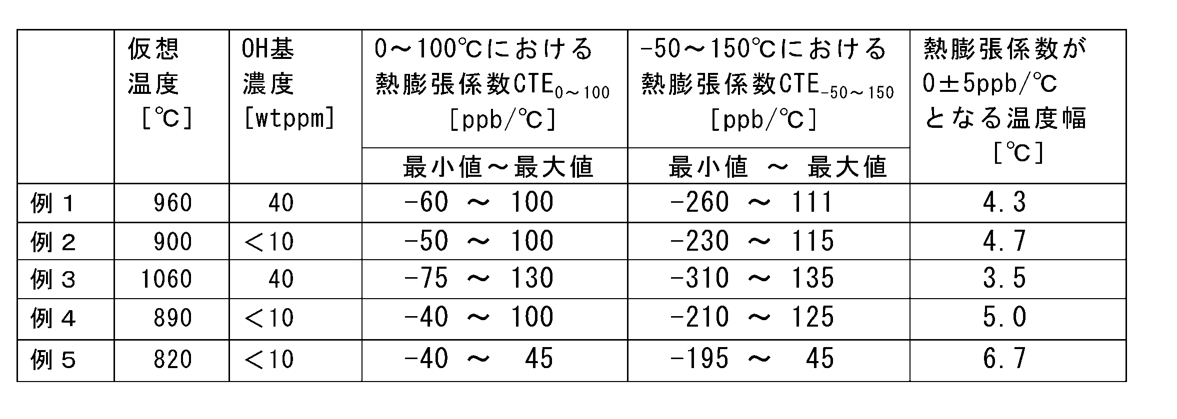
Claims (8)
- TiO2濃度が3~10質量%、Ti3+濃度が100wtppm以下、0~100℃での熱膨張係数CTE0~100が0±150ppb/℃であり、400~700nmの波長域で厚さ1mmあたりの内部透過率T400~700が80%以上であるTiO2を含有するシリカガラスからなる光学部材であって、光学使用面におけるTi3+濃度の平均値に対するTi3+濃度のばらつきの割合ΔTi3+/Ti3+が0.2以下である、光学部材。 The TiO 2 concentration is 3 to 10% by mass, the Ti 3+ concentration is 100 wtppm or less, the coefficient of thermal expansion CTE 0 to 100 at 0 to 100 ° C. is 0 ± 150 ppb / ° C., and the thickness is 1 mm in the wavelength region of 400 to 700 nm. Is an optical member made of silica glass containing TiO 2 having an internal transmittance T 400 to 700 of 80% or more, and the ratio of variation in Ti 3+ concentration to the average value of Ti 3+ concentration on the optical use surface ΔTi 3+ / An optical member having Ti 3+ of 0.2 or less.
- Fを含有し、F濃度が1000wtppm以上であるTiO2を含有するシリカガラスからなる、請求項1に記載の光学部材。 The optical member according to claim 1, wherein the optical member is made of silica glass containing TiO 2 containing F and having an F concentration of 1000 wtppm or more.
- OH濃度が600wtppm以下であるTiO2を含有するシリカガラスからなる、請求項1または請求項2に記載の光学部材。 The optical member according to claim 1 or 2, wherein the optical member is made of silica glass containing TiO 2 having an OH concentration of 600 wtppm or less.
- 300~3000nmの波長域で厚さ1mmあたりの内部透過率T300~3000が70%以上であるTiO2を含有するシリカガラスからなる、請求項1~3のいずれかに記載の光学部材。 The optical member according to any one of claims 1 to 3, comprising silica glass containing TiO 2 having an internal transmittance T 300 to 3000 of 70% or more in a wavelength region of 300 to 3000 nm per 1 mm thickness.
- 光学使用面におけるF濃度の平均値に対するF濃度のばらつきの割合ΔF/Fが0.2以下であるTiO2を含有するシリカガラスからなる、請求項2~4のいずれかに記載の光学部材。 The optical member according to any one of claims 2 to 4, wherein the optical member is made of silica glass containing TiO 2 having a F concentration variation ratio ΔF / F of 0.2 or less with respect to the average value of the F concentration on the optical use surface.
- 熱膨張係数がゼロとなる温度の分布ΔCOTが5℃以内となるTiO2を含有するシリカガラスからなる、請求項1~5のいずれかに記載の光学部材。 The optical member according to any one of claims 1 to 5, wherein the optical member is made of silica glass containing TiO 2 with a temperature distribution ΔCOT at which the coefficient of thermal expansion becomes zero within 5 ° C.
- EUVリソグラフィに用いられる、請求項1~6に記載の光学部材。 The optical member according to any one of claims 1 to 6, which is used for EUV lithography.
- 光学使用面におけるTi3+濃度の平均値に対するTi3+濃度のばらつきの割合ΔTi3+/Ti3+が0.2以下であり、Fを含有し、F濃度が1000wtppm以上である、TiO2を含有するシリカガラスからなる光学部材の製造方法であって、
ガラス形成原料を火炎加水分解して得られる石英ガラス微粒子を基材に堆積、成長させて多孔質ガラス体を形成する工程と、
前記多孔質ガラス体を、フッ素単体(F2)またはフッ素単体(F2)を不活性ガスで希釈した混合ガスで満たされた反応槽内に保持することにより、フッ素を含有した多孔質ガラス体を得る工程と、
前記フッ素を含有した多孔質ガラス体を、透明ガラス化温度まで昇温して、フッ素を含有した透明ガラス体を得る工程と、
を含む、TiO2を含有するシリカガラスからなる光学部材の製造方法。 The proportion of the variation of the Ti 3+ concentration to the average value of the Ti 3+ concentration in the optical working surfaces ΔTi 3+ / Ti 3+ is 0.2 or less, contains F, F concentration is more than 1000 wtppm, silica containing TiO 2 A method for producing an optical member made of glass,
A step of depositing and growing quartz glass fine particles obtained by flame hydrolysis of a glass forming raw material on a base material to form a porous glass body;
A porous glass body containing fluorine by holding the porous glass body in a reaction tank filled with fluorine alone (F 2 ) or a mixed gas obtained by diluting fluorine alone (F 2 ) with an inert gas. Obtaining
Heating the porous glass body containing fluorine to a transparent vitrification temperature to obtain a transparent glass body containing fluorine; and
Including, method of producing an optical member comprising silica glass containing TiO 2.
Priority Applications (4)
| Application Number | Priority Date | Filing Date | Title |
|---|---|---|---|
| JP2010546633A JP5630268B2 (en) | 2009-01-13 | 2010-01-13 | Optical member made of silica glass containing TiO 2 |
| EP10731255.5A EP2377826B2 (en) | 2009-01-13 | 2010-01-13 | OPTICAL MEMBER COMPRISING SILICA GLASS CONTAINING TiO2 |
| KR1020117016224A KR101740067B1 (en) | 2009-01-13 | 2010-01-13 | OPTICAL MEMBER COMPRISING SILICA GLASS CONTAINING TiO |
| US12/718,776 US8735308B2 (en) | 2009-01-13 | 2010-03-05 | Optical member comprising TiO2-containing silica glass |
Applications Claiming Priority (2)
| Application Number | Priority Date | Filing Date | Title |
|---|---|---|---|
| JP2009-004507 | 2009-01-13 | ||
| JP2009004507 | 2009-01-13 |
Related Child Applications (1)
| Application Number | Title | Priority Date | Filing Date |
|---|---|---|---|
| US12/718,776 Continuation US8735308B2 (en) | 2009-01-13 | 2010-03-05 | Optical member comprising TiO2-containing silica glass |
Publications (1)
| Publication Number | Publication Date |
|---|---|
| WO2010082586A1 true WO2010082586A1 (en) | 2010-07-22 |
Family
ID=42339840
Family Applications (1)
| Application Number | Title | Priority Date | Filing Date |
|---|---|---|---|
| PCT/JP2010/050286 WO2010082586A1 (en) | 2009-01-13 | 2010-01-13 | OPTICAL MEMBER COMPRISING SILICA GLASS CONTAINING TiO2 |
Country Status (4)
| Country | Link |
|---|---|
| EP (1) | EP2377826B2 (en) |
| JP (1) | JP5630268B2 (en) |
| KR (1) | KR101740067B1 (en) |
| WO (1) | WO2010082586A1 (en) |
Cited By (2)
| Publication number | Priority date | Publication date | Assignee | Title |
|---|---|---|---|---|
| JP2013199420A (en) * | 2012-02-21 | 2013-10-03 | Asahi Glass Co Ltd | Method for producing titania-containing silica glass body |
| JP2015534075A (en) * | 2012-10-24 | 2015-11-26 | ショット アクチエンゲゼルシャフトSchott AG | A method for identifying time-delayed changes in temperature-dependent or stress-dependent physical quantities of glass or glass-ceramics |
Families Citing this family (3)
| Publication number | Priority date | Publication date | Assignee | Title |
|---|---|---|---|---|
| EP3000791B1 (en) * | 2014-09-24 | 2017-04-26 | Heraeus Quarzglas GmbH & Co. KG | Method for manufacturing a blank made of fluoride and titanium doped, highly-silicate glass for use in EUV lithography and blank manufactured according to said method |
| WO2016086013A1 (en) * | 2014-11-26 | 2016-06-02 | Corning Incorporated | Method for making halogen doped optical element |
| TWI681940B (en) * | 2016-06-03 | 2020-01-11 | 日商闊斯泰股份有限公司 | Silica glass member and method of manufacturing same |
Citations (8)
| Publication number | Priority date | Publication date | Assignee | Title |
|---|---|---|---|---|
| US20020157421A1 (en) | 2001-04-27 | 2002-10-31 | Ackerman Bradford G. | Method for producing titania-doped fused silica glass |
| JP2004315351A (en) * | 2003-04-03 | 2004-11-11 | Asahi Glass Co Ltd | SILICA GLASS CONTAINING TiO2 AND OPTICAL MEMBER FOR EUV LITHOGRAPHY |
| JP2005104820A (en) | 2003-04-03 | 2005-04-21 | Asahi Glass Co Ltd | SILICA GLASS CONTAINING TiO2 AND PROCESS FOR PRODUCTION THEREOF |
| JP2006103988A (en) * | 2004-10-01 | 2006-04-20 | Asahi Glass Co Ltd | MANUFACTURING METHOD OF SILICA GLASS CONTAINING TiO2 |
| JP2006210404A (en) * | 2005-01-25 | 2006-08-10 | Asahi Glass Co Ltd | METHOD OF MANUFACTURING SILICA GLASS CONTAINING TiO2, AND OPTICAL MEMBER FOR EUV LITHOGRAPHY EMPLOYING SILICA GLASS CONTAINING TiO2 |
| JP2008505043A (en) | 2004-07-01 | 2008-02-21 | 旭硝子株式会社 | Silica glass containing TiO2 and method for producing the same |
| JP2008100891A (en) * | 2006-10-20 | 2008-05-01 | Covalent Materials Corp | Titania-silica glass |
| JP2009004507A (en) | 2007-06-20 | 2009-01-08 | Shinko Electric Ind Co Ltd | Package for electronic component, manufacturing method thereof, and electronic component device |
Family Cites Families (6)
| Publication number | Priority date | Publication date | Assignee | Title |
|---|---|---|---|---|
| DE2420476A1 (en) * | 1974-04-27 | 1975-11-06 | Licentia Gmbh | Optical waveguides mfr. - avoiding presence of trivalent titanium in deposited layer, thus preventing high attenuation |
| FR2476058A1 (en) * | 1980-02-15 | 1981-08-21 | Quartz Silice Sa | SEMI-PRODUCT FOR THE PRODUCTION OF OPTICAL FIBERS, PROCESS FOR PREPARING THE SEMICONDUCTOR AND OPTICAL FIBERS OBTAINED FROM THE SEMICONDUCTOR |
| US7155936B2 (en) † | 2003-08-08 | 2007-01-02 | Corning Incorporated | Doped silica glass articles and methods of forming doped silica glass boules and articles |
| JP5035516B2 (en) † | 2005-12-08 | 2012-09-26 | 信越化学工業株式会社 | Method for producing titania-doped quartz glass for photomask |
| JP2009013048A (en) † | 2007-06-06 | 2009-01-22 | Shin Etsu Chem Co Ltd | Titania-doped quartz glass for nanoimprint molds |
| JP5042714B2 (en) † | 2007-06-06 | 2012-10-03 | 信越化学工業株式会社 | Titania-doped quartz glass for nanoimprint molds |
-
2010
- 2010-01-13 JP JP2010546633A patent/JP5630268B2/en active Active
- 2010-01-13 KR KR1020117016224A patent/KR101740067B1/en active IP Right Grant
- 2010-01-13 EP EP10731255.5A patent/EP2377826B2/en active Active
- 2010-01-13 WO PCT/JP2010/050286 patent/WO2010082586A1/en active Application Filing
Patent Citations (8)
| Publication number | Priority date | Publication date | Assignee | Title |
|---|---|---|---|---|
| US20020157421A1 (en) | 2001-04-27 | 2002-10-31 | Ackerman Bradford G. | Method for producing titania-doped fused silica glass |
| JP2004315351A (en) * | 2003-04-03 | 2004-11-11 | Asahi Glass Co Ltd | SILICA GLASS CONTAINING TiO2 AND OPTICAL MEMBER FOR EUV LITHOGRAPHY |
| JP2005104820A (en) | 2003-04-03 | 2005-04-21 | Asahi Glass Co Ltd | SILICA GLASS CONTAINING TiO2 AND PROCESS FOR PRODUCTION THEREOF |
| JP2008505043A (en) | 2004-07-01 | 2008-02-21 | 旭硝子株式会社 | Silica glass containing TiO2 and method for producing the same |
| JP2006103988A (en) * | 2004-10-01 | 2006-04-20 | Asahi Glass Co Ltd | MANUFACTURING METHOD OF SILICA GLASS CONTAINING TiO2 |
| JP2006210404A (en) * | 2005-01-25 | 2006-08-10 | Asahi Glass Co Ltd | METHOD OF MANUFACTURING SILICA GLASS CONTAINING TiO2, AND OPTICAL MEMBER FOR EUV LITHOGRAPHY EMPLOYING SILICA GLASS CONTAINING TiO2 |
| JP2008100891A (en) * | 2006-10-20 | 2008-05-01 | Covalent Materials Corp | Titania-silica glass |
| JP2009004507A (en) | 2007-06-20 | 2009-01-08 | Shinko Electric Ind Co Ltd | Package for electronic component, manufacturing method thereof, and electronic component device |
Non-Patent Citations (4)
| Title |
|---|
| BULLETIN OF THE CHEMICAL SOCIETY OF JAPAN, 1972, pages 350 |
| J. P. WILLIAMS ET AL., CERAMIC BULLETIN, vol. 55, no. 5, 1976, pages 524 |
| JOURNAL OF APPLIED PHYSICS, vol. 91, no. 8, 2002, pages 4886 |
| See also references of EP2377826A4 * |
Cited By (2)
| Publication number | Priority date | Publication date | Assignee | Title |
|---|---|---|---|---|
| JP2013199420A (en) * | 2012-02-21 | 2013-10-03 | Asahi Glass Co Ltd | Method for producing titania-containing silica glass body |
| JP2015534075A (en) * | 2012-10-24 | 2015-11-26 | ショット アクチエンゲゼルシャフトSchott AG | A method for identifying time-delayed changes in temperature-dependent or stress-dependent physical quantities of glass or glass-ceramics |
Also Published As
| Publication number | Publication date |
|---|---|
| EP2377826A1 (en) | 2011-10-19 |
| EP2377826B1 (en) | 2016-11-16 |
| KR101740067B1 (en) | 2017-05-25 |
| KR20110108351A (en) | 2011-10-05 |
| EP2377826B2 (en) | 2020-05-27 |
| EP2377826A4 (en) | 2014-05-07 |
| JP5630268B2 (en) | 2014-11-26 |
| JPWO2010082586A1 (en) | 2012-07-05 |
Similar Documents
| Publication | Publication Date | Title |
|---|---|---|
| JP4957249B2 (en) | Silica glass containing TiO2 and method for producing the same | |
| JP4792706B2 (en) | Silica glass containing TiO2 and method for producing the same | |
| JP4487783B2 (en) | Method for producing silica glass containing TiO2 and optical member for EUV lithography using silica glass containing TiO2 | |
| JP5644058B2 (en) | Silica glass containing TiO2 | |
| JP5754482B2 (en) | Silica glass containing TiO2 | |
| WO2010131662A1 (en) | Method for producing tio2-sio2 glass body, method for heat-treating tio2-sio2 glass body, tio2-sio2 glass body, and optical base for euvl | |
| US8735308B2 (en) | Optical member comprising TiO2-containing silica glass | |
| KR20100099211A (en) | Tio2-containing silica glass | |
| WO2011021609A1 (en) | Tio2-containing silica glass, and optical member for euv lithography | |
| KR20100118125A (en) | Tio2-containing silica glass and optical member for lithography using the same | |
| JP2009227572A (en) | TiO2-CONTAINING SILICA GLASS AND OPTICAL MEMBER FOR LITHOGRAPHY USING THE SAME | |
| WO2011068064A1 (en) | Silica glass containing tio2 | |
| JP5630268B2 (en) | Optical member made of silica glass containing TiO 2 | |
| JP4513486B2 (en) | Method for producing silica glass containing TiO2 | |
| US20130276480A1 (en) | Method for producing tio2-sio2 glass body, method for heat-treating tio2-sio2 glass body, tio2-sio2 glass body, and optical base for euvl | |
| JP5417889B2 (en) | Silica glass containing TiO2 and optical member for lithography using the same | |
| JP5402975B2 (en) | Silica glass containing TiO2 and method for producing the same |
Legal Events
| Date | Code | Title | Description |
|---|---|---|---|
| 121 | Ep: the epo has been informed by wipo that ep was designated in this application |
Ref document number: 10731255 Country of ref document: EP Kind code of ref document: A1 |
|
| ENP | Entry into the national phase |
Ref document number: 2010546633 Country of ref document: JP Kind code of ref document: A |
|
| REEP | Request for entry into the european phase |
Ref document number: 2010731255 Country of ref document: EP |
|
| WWE | Wipo information: entry into national phase |
Ref document number: 2010731255 Country of ref document: EP |
|
| ENP | Entry into the national phase |
Ref document number: 20117016224 Country of ref document: KR Kind code of ref document: A |
|
| NENP | Non-entry into the national phase |
Ref country code: DE |