WO2010079735A1 - めっき用銅材及びめっき用銅材の製造方法、並びに銅めっき材の製造方法 - Google Patents
めっき用銅材及びめっき用銅材の製造方法、並びに銅めっき材の製造方法 Download PDFInfo
- Publication number
- WO2010079735A1 WO2010079735A1 PCT/JP2010/000014 JP2010000014W WO2010079735A1 WO 2010079735 A1 WO2010079735 A1 WO 2010079735A1 JP 2010000014 W JP2010000014 W JP 2010000014W WO 2010079735 A1 WO2010079735 A1 WO 2010079735A1
- Authority
- WO
- WIPO (PCT)
- Prior art keywords
- copper
- plating
- plated
- copper material
- solution
- Prior art date
- Legal status (The legal status is an assumption and is not a legal conclusion. Google has not performed a legal analysis and makes no representation as to the accuracy of the status listed.)
- Ceased
Links
Images





Classifications
-
- C—CHEMISTRY; METALLURGY
- C25—ELECTROLYTIC OR ELECTROPHORETIC PROCESSES; APPARATUS THEREFOR
- C25D—PROCESSES FOR THE ELECTROLYTIC OR ELECTROPHORETIC PRODUCTION OF COATINGS; ELECTROFORMING; APPARATUS THEREFOR
- C25D21/00—Processes for servicing or operating cells for electrolytic coating
- C25D21/12—Process control or regulation
- C25D21/14—Controlled addition of electrolyte components
-
- C—CHEMISTRY; METALLURGY
- C25—ELECTROLYTIC OR ELECTROPHORETIC PROCESSES; APPARATUS THEREFOR
- C25D—PROCESSES FOR THE ELECTROLYTIC OR ELECTROPHORETIC PRODUCTION OF COATINGS; ELECTROFORMING; APPARATUS THEREFOR
- C25D17/00—Constructional parts, or assemblies thereof, of cells for electrolytic coating
- C25D17/10—Electrodes, e.g. composition, counter electrode
- C25D17/12—Shape or form
-
- C—CHEMISTRY; METALLURGY
- C25—ELECTROLYTIC OR ELECTROPHORETIC PROCESSES; APPARATUS THEREFOR
- C25D—PROCESSES FOR THE ELECTROLYTIC OR ELECTROPHORETIC PRODUCTION OF COATINGS; ELECTROFORMING; APPARATUS THEREFOR
- C25D21/00—Processes for servicing or operating cells for electrolytic coating
- C25D21/16—Regeneration of process solutions
- C25D21/18—Regeneration of process solutions of electrolytes
Definitions
- the present invention relates to a copper material for plating used as a copper ion supply source in electrolytic plating of copper, a method for producing a copper material for plating, and a method for producing a copper plating material using the copper material for plating.
- the present application includes Japanese Patent Application No. 2009-002624 filed in Japan on January 8, 2009, Japanese Patent Application No. 2009-034611, filed in Japan on February 17, 2009, and Japan on October 20, 2009. The priority is claimed based on Japanese Patent Application No. 2009-241404 filed in Japan, the contents of which are incorporated herein by reference.
- electrolytic plating has been widely used as a method for copper plating on printed wiring boards such as mobile phones and computers.
- copper is immersed as a soluble anode and a printed wiring board is immersed as a cathode in a plating tank in which a plating solution such as a dilute sulfuric acid solution containing copper ions is stored.
- a plating solution such as a dilute sulfuric acid solution containing copper ions is stored.
- a plating solution such as a dilute sulfuric acid solution containing copper ions
- electrolytic plating in which an insoluble anode such as iridium oxide is immersed in a plating tank is also widely used.
- a method utilizing electrolysis or a method utilizing a chemical reaction may be mentioned.
- a copper material (copper ball for plating) formed in a ball shape or a circle obtained by cutting a copper wire Columnar copper is widely used.
- this copper ball for plating as a soluble anode, a basket made of a corrosion-resistant material such as Ti is disposed in the plating tank, and the copper ball for plating is inserted into the basket. .
- the copper balls for plating are gradually consumed as they dissolve in the plating solution, but by continuously replenishing the Ti basket with new copper balls for plating according to the amount consumed, electrolysis can be performed continuously.
- Plating can be performed.
- the copper balls for plating are dissolved in a sulfuric acid solution or the like outside the plating tank and are sequentially supplied into the plating tank.
- the above-mentioned copper balls for plating are made of low oxygen copper, oxygen-free copper, phosphorous deoxidized copper or the like having an oxygen content of 20 ppm or less, and have a diameter of about 10 mm to 60 mm.
- a copper ball for plating is obtained by cutting a long copper rod material to obtain a substantially cylindrical copper rod material, and rolling the copper rod material or It is formed by forging.
- a black film containing copper oxide as a main component is formed on the surface of the plating copper material. It is known that a black film formed uniformly and thinly has the effect of suppressing the disproportionation reaction described below to prevent passivation and assisting good dissolution. 2Cu + ⁇ Cu 2+ + Cu (fine powder)
- the flow of the plating solution is weak, and when the divalent copper ions generated by electrolysis stay near the surface of the plating copper material and the concentration of the divalent copper ions near the surface increases, monovalent copper ions are likely to be generated. Thus, the disproportionation reaction proceeds and a large amount of fine copper powder is generated.
- Patent Document 5 proposes removing black film and anode slime generated on the surface of the copper material for plating by bubbling.
- the present invention has been made in view of the above-described circumstances, and the ratio S / V between the surface area S and the volume V is large, and copper ions can be efficiently supplied into a plating solution made of a sulfuric acid solution or the like.
- Copper plating material capable of being efficiently plated while suppressing generation of copper powder, a method for producing the copper material for plating, and production of a copper plating material using the copper material for plating It aims to provide a method.
- the copper material for plating which concerns on this invention consists of a coil body by which the copper wire was wound helically, and is used when supplying copper ion in a plating solution.
- the plating copper material of this configuration since the copper wire is a coil body wound spirally, the outer peripheral surface of the copper wire is exposed to the outer peripheral side and the inner peripheral side of the coil body, The ratio S / V between the surface area S and the volume V increases. Therefore, copper is easily dissolved in a plating solution such as a sulfuric acid solution, and copper ions can be efficiently supplied into the plating solution. Moreover, since it contacts with the plating solution on the inner peripheral surface of the coil body, even if a plurality of copper materials for plating overlap, copper is dissolved from the inner peripheral surface of the coil body, Copper ions can be supplied more efficiently.
- the outer diameter of the said copper wire which comprises a coil body is 1.5 mm or more and 5 mm or less.
- the outer diameter of the copper wire is 1.5 mm or more, so that the rigidity of the copper wire is ensured. For this reason, even when a plurality of copper plating materials overlap each other, the copper plating material does not deform so as to be crushed, and dissolves by contacting with a plating solution such as a sulfuric acid solution on the inner peripheral side of the plating copper material. It becomes possible to do.
- the outer diameter of the copper wire is 5 mm or less, the ratio S / V between the surface area S and the volume V can be increased, and the plating copper material can be efficiently dissolved.
- the copper wire preferably has a tensile strength of 350 MPa or more.
- the tensile strength of the copper wire is 350 MPa or more, so that the rigidity of the copper wire is ensured. For this reason, even when a plurality of copper plating materials overlap each other, the copper plating material does not deform so as to be crushed, and dissolves by contacting with a plating solution such as a sulfuric acid solution on the inner peripheral side of the plating copper material. It becomes possible to do. In order to ensure that this effect is achieved, it is more preferable that the tensile strength of the copper wire is 400 MPa or more.
- the method for producing a copper material for plating according to the present invention includes a copper wire supplying step for supplying a copper wire, a coil forming step for winding the supplied copper wire into a coil shape, and a coil body having a predetermined length is formed. A cutting step of cutting the copper wire, and manufacturing the above-described copper material for plating. According to the method for producing a copper material for plating having this configuration, it is possible to continuously produce a copper material for plating comprising a coil body in which copper wires are spirally wound.
- the copper material for plating is made of a coil body in which a copper wire is spirally wound, the flow rate of the plating solution is ensured by passing the plating solution through the inner peripheral side of the coil body.
- the concentration of divalent copper ions does not become higher than necessary around the copper material. Therefore, generation
- the second aspect of the method for producing a copper plating material according to the present invention includes a step of immersing the material to be plated as a cathode in a plating tank in which a plating solution is stored and immersing an insoluble anode in the plating tank; A step of depositing copper on the surface of the material to be plated by energizing the insoluble anode and the cathode, and the plating solution contains copper ions by dissolving the copper material for plating according to the present invention described above.
- the plating solution is supplied to the plating tank.
- a plating solution is produced
- the third aspect of the method for producing a copper plating material according to the present invention includes a step of immersing the material to be plated as a cathode in a plating tank in which a plating solution is stored, and immersing an insoluble anode in the plating tank; And a step of depositing copper on the surface of the material to be plated by energizing the insoluble anode and the cathode, and the plating solution is obtained by dissolving the above-described plating copper material according to the present invention by a chemical reaction. It is generated by supplying copper ions, and the plating solution is supplied to the plating tank.
- the method for producing a copper plating material of this configuration since the plating copper material is dissolved using a chemical reaction, the black film and the anode slime are not generated, and the plating copper material is dissolved well. It becomes possible. Further, as described above, since the ratio S / V between the surface area S and the volume V of the copper material for plating is larger than that of the conventional copper ball for plating, the reaction area is ensured and the dissolution rate can be improved. it can.
- the ratio S / V between the surface area S and the volume V is large, copper ions can be efficiently supplied into a plating solution containing a sulfuric acid solution and the like, and the generation of copper powder is suppressed and efficiency is increased. It is possible to provide a copper material for plating that can be plated well, a method for producing the copper material for plating, and a method for producing a copper plated material using the copper material for plating.
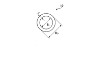
- the plating copper material 10 of the present embodiment is formed of a coil body in which a copper wire is spirally wound, and in this embodiment, the outer shape is cylindrical.
- the diameter r of the copper wire forming the plating copper material 10 is set in a range of 1.5 mm ⁇ r ⁇ 5 mm, and in this embodiment, 2.6 mm ⁇ r ⁇ 3.2 mm. Yes.
- the copper wire is made of low oxygen copper or oxygen-free copper having a copper purity of 99.96% or more and an oxygen content of 20 ppm or less, and the tensile strength TS of the copper wire is TS ⁇ 350 MPa.
- the outer diameter Ro of the cylinder formed by the plating copper material (coil body) 10 is set within a range of 4.5 mm ⁇ Ro ⁇ 20 mm, and the inner diameter Ri is set within a range of 1.5 mm ⁇ Ri ⁇ 16 mm.
- the length L of the plating copper material (coil body) 10 is set in a range of 5 mm ⁇ L ⁇ 50 mm.
- the pitch P of the wound copper wire is set within the range of (r + 0.1) mm ⁇ P ⁇ (3 ⁇ r) mm with respect to the diameter r of the copper wire. It is set within the range of 6 mm ⁇ P ⁇ 15 mm.
- a copper wire made of low-oxygen copper or oxygen-free copper having a copper purity of 99.96% or more and an oxygen content of 20 ppm or less and having a diameter r in a range of 1.5 mm ⁇ r ⁇ 5 mm is produced.
- Copper wire production process S1 In order to efficiently produce such a copper wire, for example, while continuously producing a long bar-shaped ingot using a belt wheel type continuous casting machine, the bar-shaped ingot is continuously rolled to produce copper rough.
- Manufactures drawn wires the rough copper wire is processed into a hard copper wire by a cold wire drawing process. At this time, rolling conditions, heat treatment conditions, cold wire drawing process conditions, etc. are set so that the tensile strength TS of the copper wire (hard copper wire) is TS ⁇ 350 MPa, and more preferably TS ⁇ 400 MPa.
- a copper wire having a diameter r in the range of 1.5 mm ⁇ r ⁇ 5 mm is supplied to the coil forming machine (copper wire supplying step S2).
- the coil body is formed by sequentially bending the copper wire while feeding the copper wire (coil forming step S3). And a copper wire is cut
- the copper material 10 for plating of this embodiment is produced.
- FIG. 4 shows an example (first embodiment) in which the copper material 10 for plating of this embodiment is used as a soluble anode.
- This plating apparatus 20 accommodates a plating tank 21 in which a plating solution 2 made of a sulfuric acid solution or the like is stored, a material 6 to be plated on which a copper plating film 7 is formed, and a copper material 10 for plating of this embodiment. And a basket 23.
- the basket 23 is made of a corrosion resistant material such as Ti.
- the material 6 to be plated is a cathode
- the copper material 10 for plating accommodated in the basket 23 is a soluble anode, and the cathode and the anode are energized.
- the plating copper material 10 accommodated in the basket 23 is dissolved in the plating solution 2, and thereby, copper ions are supplied into the plating solution 2.
- the copper ions are electrodeposited on the surface of the cathode (material to be plated 6), and a copper plating film 7 is formed on the surface of the material to be plated 6.
- the plating copper material 10 gradually dissolves and decreases. Therefore, it is preferable to provide a means for supplying the plating copper material 10 into the basket 23 as appropriate.
- FIG. 5 shows an example (second embodiment) in which copper ions are supplied using the plating copper material 10 of the present embodiment and copper plating is performed using an insoluble anode.
- the plating apparatus 30 includes a plating tank 31 in which a plating solution 2 made of a sulfuric acid solution or the like is stored, a material to be plated 6 on which a copper plating film 7 is formed, an insoluble anode 33 made of iridium oxide, and the like.
- a copper ion supply device 40 that supplies copper ions therein, and a communication path 37 that connects the copper ion supply device 40 and the plating tank 31 are provided.
- the copper ion supply device 40 is provided in an ion generation tank 41 in which the plating solution 2 is stored, a hydrogen ion exchange membrane 45 that partitions the ion generation tank 41 into a cathode chamber 41A and an anode chamber 41B, and the cathode chamber 41A. And a basket 43 that is disposed in the anode chamber 41B and that accommodates the copper material for plating 10 of the present embodiment.
- the communication path 37 that connects the copper ion supply device 40 and the plating tank 31 is connected to the anode chamber 41 ⁇ / b> B of the ion generation tank 41.
- the copper ion supply device 40 electricity is supplied between the basket 43 and the copper material 10 for plating accommodated in the basket 43 as an anode and the cathode portion 44 of the cathode chamber 41 ⁇ / b> A. Then, the copper material for plating 10 is dissolved in the plating solution 2 and copper ions are supplied into the plating solution 2.
- the hydrogen ions existing in the anode chamber 41B pass through the hydrogen ion exchange membrane 45 and enter the cathode chamber 41A, and are released to the outside as hydrogen gas from the surface of the cathode portion 44.
- the plating solution 2 supplied with copper ions in the anode chamber 41 ⁇ / b> B is supplied into the plating tank 31 through the communication path 37.
- the copper ions in the plating solution 2 are electrodeposited on the surface of the cathode (material 6) to be plated.
- a copper plating film 7 is formed on the surface of the material 6.
- the plating copper material 10 of the present embodiment since the copper wire is formed of a coil body wound spirally, the outer peripheral surface of the copper wire is exposed to the outer peripheral side and the inner peripheral side of the coil body.
- the ratio S / V between the surface area S and the volume V increases.
- copper is easily dissolved in the plating solution 2 such as a sulfuric acid solution, and copper ions can be efficiently supplied into the plating solution 2.
- the inner peripheral surface of the plating copper material 10 is also in contact with the plating solution 2, even if a plurality of plating copper materials 10 are charged in the baskets 23 and 43, the cylindrical copper plating material 10 is formed. Copper is melted from the inner peripheral surface (inner peripheral side). For this reason, the supply of the copper ions into the plating solution 2 can be performed more efficiently.
- the outer diameter r of the copper wire is set within a range of 1.5 mm ⁇ r ⁇ 5 mm, and more specifically within a range of 2.6 mm ⁇ r ⁇ 3.2 mm. Since it is set, the rigidity of the copper wire is ensured. For this reason, even if it is a case where the several copper material 10 for plating overlaps, it does not deform
- the copper wire whose outer diameter r is set within the range of 2.6 mm ⁇ r ⁇ 3.2 mm is obtained by the continuous casting rolling means using the belt wheel type continuous casting machine and the cold wire drawing process as described above. Since it can produce well, the copper material 10 for plating of this embodiment can be produced efficiently.
- the tensile strength TS of the copper wire is set to TS ⁇ 350 MPa, more preferably TS ⁇ 400 MPa, the rigidity of the copper wire is ensured. For this reason, even if it is a case where the several copper material 10 for plating overlaps, it does not deform
- the pitch P of the wound copper wire is set within the range of (r + 0.1) mm ⁇ P ⁇ (3 ⁇ r) mm with respect to the diameter r of the copper wire, Specifically, it is set within a range of 1.6 mm ⁇ P ⁇ 15 mm.
- the plating solution 2 such as a sulfuric acid solution is introduced into the inner peripheral side of the plating copper material 10 from the gap between adjacent copper wires, and the dissolution of the plating copper material 10 is promoted.
- the copper wires of the other plating copper materials 10 are not sandwiched between the gaps and the plating copper materials 10 are not entangled with each other, the dissolution of the plating copper material 10 can be promoted.
- the copper wire 10 is continuously formed by introducing the copper wire into the coil forming machine. For this reason, the copper material 10 for plating of this embodiment can be produced efficiently. Furthermore, in this embodiment, a continuous cast rolling means for continuously producing a long bar-shaped ingot using a belt wheel type continuous caster and continuously rolling the bar-shaped ingot is used. For this reason, a high quality copper wire can be produced efficiently at low cost, and the copper material 10 for plating of this embodiment can be produced more efficiently.
- the copper material for plating 10 is efficiently dissolved in the plating solution 2, Copper ions are supplied into the plating solution 2. For this reason, copper plating can be performed efficiently.
- the copper ion supply apparatus 40 when the copper ion supply apparatus 40 is used, also in the manufacturing method of the copper plating material using the insoluble anode 33, the copper material 10 for plating of this embodiment can be used. .
- the copper material for plating 10 is dissolved by an electrolytic method.
- a black film grows thick on the surface of the plating copper material 10 and anode slime is easily generated.
- the plating solution 2 can pass the inner peripheral side of the copper material 10 for plating, A flow rate is ensured.
- concentration of a bivalent copper ion does not become high more than necessary around the copper material 10 for plating. For this reason, generation
- FIG. 6 shows an example (third embodiment) in which the plating copper material 10 of this embodiment is dissolved by a chemical reaction to supply copper ions and copper plating is performed using an insoluble anode.
- the plating apparatus 90 includes a plating tank 91 that stores a plating solution 2 made of a copper sulfate solution, an iron sulfate solution, a sulfuric acid solution, and the like, a material to be plated 6 on which a copper plating film 7 is formed, iridium oxide, and the like.
- the copper ion supply device 96 includes an ion generation tank 97 in which the plating solution 2 is stored, and a basket 98 that is immersed in the plating solution 2 in the ion generation tank 97.
- a plating solution in which iron sulfate is dissolved and Fe 2+ ions and Fe 3+ ions are contained is used. use.
- the plating copper material 10 of this embodiment is accommodated in the basket 98 and immersed in the plating solution 2. Then, the copper material for plating 10 is dissolved in the plating solution 2 by the following chemical reaction, and copper ions are supplied into the plating solution 2. Cu + 2Fe 3+ ⁇ Cu 2+ + 2Fe 2+ The plating solution 2 supplied with copper ions in the ion supply tank 97 is supplied to the plating tank 91 through the communication path 94.
- this plating tank 91 by energizing the insoluble anode 93 and the material to be plated 6 that is the cathode, copper ions in the plating solution 2 are electrodeposited on the surface of the material to be plated 6, and A copper plating film is formed on the surface.
- the plating copper material 10 is a coil body in which a copper wire is spirally wound. Therefore, the outer peripheral surface of the copper wire is exposed to the outer peripheral side and the inner peripheral side of the coil body, and the ratio S / V between the surface area S and the volume V is increased.
- the plating copper material 10 is dissolved by utilizing the oxidation-reduction reaction of iron ions, the dissolution rate greatly depends on the area where the chemical reaction occurs. Therefore, when the ratio S / V between the surface area S and the volume V is increased, the dissolution rate can be significantly improved.
- the plating copper material 10 is formed of a coil body in which a copper wire is spirally wound, the flow of the plating solution 2 on the surface of the plating copper material 10 becomes smooth. For this reason, supply of copper and iron ions is performed rapidly, and the dissolution rate of copper is further improved. This is because the copper dissolution reaction is a diffusion-controlled reaction governed by the supply rate of copper and iron ions.
- the present invention is not limited to this, and can be appropriately changed without departing from the technical idea of the present invention.
- the copper material for plating the copper wire made of low-oxygen copper or oxygen-free copper has been exemplified and described, but the present invention is not limited to this. It may be produced by coil-forming a copper wire made of a phosphorus-containing copper alloy containing 0.03% by mass or more and 0.08% by mass or less of phosphorus.
- the copper material for plating may be made of tough pitch copper (TPC) or high-purity copper (5N copper, 6N copper, etc.) having a purity of 99.999% or more excluding gas components.
- the plating copper material when the plating copper material is dissolved by electrolysis, it is preferable to use a plating copper material made of a phosphorus-containing copper alloy containing phosphorus as described above.
- a plating copper material made of a phosphorus-containing copper alloy is dissolved by electrolysis, a black film is uniformly and thinly formed on the surface of the plating copper material. This black film suppresses the disproportionation reaction, prevents passivation, and can satisfactorily dissolve the plating copper material.
- the plating copper material when the plating copper material is dissolved by a chemical reaction, it is not necessary to use a black film. Therefore, it is preferable to use a plating copper material made of oxygen-free copper or the like.
- the material to be plated 6 is not particularly limited, and the copper material for plating of the present invention can be used in copper plating for various materials to be plated.
- the copper material for plating of the present invention can be used in copper plating for various materials to be plated.
- it can be used for copper plating on printed wiring boards, copper plating for semiconductors, copper plating on plastic materials, copper plating on steel plates, and the like.
- the present invention is not limited thereto.
- the outer shape may be conical as shown in FIG.
- the center diameter may be reduced as shown in FIG. 8, or the center diameter may be increased as shown in FIG.
- the winding pitch P may be changed.
- the configuration of the plating apparatus for performing copper plating is not limited to the one described in FIGS. 4 to 6, and the design can be changed as appropriate.
- the method of producing a copper wire by the continuous casting rolling means using the belt wheel type continuous casting machine it is not limited to this.
- the copper wire may be produced by other means such as extrusion.
- the copper ion supply apparatus 40 shown in FIG. 5 although the copper ion was produced
- copper ions may be generated using a method of immersing and dissolving a copper material in hot concentrated sulfuric acid (for example, temperature 70 ° C., concentration 98%).
- the method of dissolving the copper material 10 for plating using the redox reaction of iron ions has been described as an example, but the method for generating copper ions is limited to this. It will never be done.
- copper ions may be generated by a method of supplying air or oxygen gas into the plating solution and oxidizing and dissolving copper with oxygen.
- the immersion method of the copper material 10 for plating is limited to this. It will never be done.
- the plating copper material 10 may be directly immersed in the plating solution 2 of the ion generation tank 97.
- Example 1 shows the results of calculating the ratio S / V of the surface area S to the volume V for the plating copper material of the present invention and the conventionally used plating copper balls.
- a conventional example is a copper ball for plating having a diameter of 11 mm that is generally widely used.
- the copper material for plating of the example of the present invention was prepared by cutting a copper wire having a diameter of 2.6 mm with the same volume as the copper ball for plating of the conventional example and winding it in a coil shape.
- the ratio S / V of the surface area S to the volume V was about 2.85 times compared to the conventional example. For this reason, a contact area with a plating solution increases and it is anticipated that the melt
- Example 2 Next, a comparative evaluation was made on the dissolution rate when the plating copper material of the present invention and the conventional copper ball for plating of the conventional example were dissolved by a chemical reaction.
- the copper material for plating of the present invention example and the copper ball for plating of the conventional example were each accommodated in a Ti basket 198.
- a Ti basket 198 in which the copper material for plating of the present invention example and the copper ball for plating of the conventional example were respectively accommodated was immersed in an ion generation tank 197.
- a cathode plate 106 and an insoluble anode 193 made of iridium oxide or the like were immersed in a plating tank 191 connected to the ion generation tank 197 by a communication path 194.
- a plating solution having the following composition was used, the amount of the plating solution being 30 L, and the temperature of the plating solution being 21 to 25 ° C.
- the ratio S / V between the surface area S and the volume V is about 2.85 times that of the conventional example, but the dissolution amount is 3. 34 times. It is presumed that this is because copper and iron ions were smoothly supplied because the flow of the plating solution was promoted (the plating solution was difficult to stay) in addition to the effect of increasing the surface area.
- the copper material for plating of the present invention is particularly effective when the copper material for plating is dissolved using a chemical reaction.
- Example 3 Next, the amount of anode slime produced when the copper material for plating of the present invention and the conventional copper ball for plating of the conventional example were dissolved by electrolysis was compared and evaluated. Thirty pieces of the copper material for plating of the example of the present invention of Example 1 or copper balls for plating of the conventional example were accommodated in the Ti basket 198. As shown in FIG. 12, the Ti basket 123 containing the plating copper material of the present invention example or the conventional plating copper ball and the cathode plate 106 were immersed in the plating solution 102. Then, electrolysis was performed by applying a current of 2.5 A to dissolve the copper material for plating of the present invention example or the copper ball for plating of the conventional example. And the amount of slime after performing electrolysis for one week was measured.
- the amount of the plating solution was 5 L, and the temperature of the plating solution was 21 to 25 ° C.
- Additive containing disulfide compound 1.5 mL / L
- Additives containing polyethylene glycol 15 mL / L
- the amount of anode slime after electrolysis for one week was 2.53 g in the conventional example, and 1.08 g in the present invention example.
- the amount of anode slime generated can be suppressed by using the coiled copper plating material of the present invention. confirmed.
- the copper material for plating of the present invention When the copper material for plating of the present invention is used in a method for producing a copper plating material, copper ions can be efficiently supplied into a plating solution composed of a sulfuric acid solution and the like, and the generation of copper powder can be suppressed. Thereby, plating can be performed efficiently. For this reason, this invention can be applied suitably, for example to the copper plating to a printed wiring board, the copper plating for semiconductors, the copper plating to a plastic material, the copper plating to a steel plate, etc.
Landscapes
- Chemical & Material Sciences (AREA)
- Engineering & Computer Science (AREA)
- Chemical Kinetics & Catalysis (AREA)
- Electrochemistry (AREA)
- Materials Engineering (AREA)
- Metallurgy (AREA)
- Organic Chemistry (AREA)
- Automation & Control Theory (AREA)
- Electroplating And Plating Baths Therefor (AREA)
- Electroplating Methods And Accessories (AREA)
Abstract
このめっき用銅材は、銅線が螺旋状に巻かれたコイル体からなる。このめっき用銅材の製造方法は、銅線を供給する工程と、供給された銅線をコイル状に巻く工程と、所定長さのコイル体を成形した後に銅線を切断する工程を有する。この銅めっき材の製造方法の一態様は、めっき液が貯留されためっき槽内に、被めっき材を陰極として浸漬するとともに、溶解性陽極を浸漬する工程と、溶解性陽極及び陰極に通電して被めっき材の表面に銅を電析させる工程を有し、溶解性陽極として前記めっき用銅材を用いる。この銅めっき材の製造方法の他の態様は、めっき液が貯留されためっき槽内に、被めっき材を陰極として浸漬するとともに、不溶性陽極を浸漬する工程と、不溶性陽極及び陰極に通電して被めっき材の表面に銅を電析させる工程を有し、めっき液は、前記めっき用銅材を溶解することにより銅イオンを供給して生成され、めっき液をめっき槽に供給する。
Description
本発明は、銅の電解めっきにおいて銅イオンの供給源として使用されるめっき用銅材及びめっき用銅材の製造方法、並びに、このめっき用銅材を用いた銅めっき材の製造方法に関する。
本願は、2009年1月8日に日本に出願された特願2009-002624号、2009年2月17日に日本に出願された特願2009-034611号、及び2009年10月20日に日本に出願された特願2009-241404号に基づき優先権を主張し、その内容をここに援用する。
本願は、2009年1月8日に日本に出願された特願2009-002624号、2009年2月17日に日本に出願された特願2009-034611号、及び2009年10月20日に日本に出願された特願2009-241404号に基づき優先権を主張し、その内容をここに援用する。
従来、携帯電話やコンピュータなどのプリント配線基板に銅めっきをする方法として、電解めっきが広く使用されている。この電解めっきでは、銅イオンを含有した希硫酸溶液等のめっき液が貯留されためっき槽内に、銅を溶解性陽極として浸漬するとともに、プリント配線基板を陰極として浸漬し、これら陽極及び陰極に通電する。このように溶解性陽極を用いた電解めっきにおいては、陽極とされた銅が希硫酸溶液中に溶け出して銅イオンとなり、陰極とされたプリント配線基板の表面に銅が電析されることになる。すなわち、めっき用銅材を電解にて溶解しているのである。
また、前記溶解性陽極の代わりに、酸化イリジウム等の不溶解性陽極をめっき槽内に浸漬した電解めっきも広く使用されている。この場合、銅を硫酸液等に溶解することによって、めっき槽中のめっき液に対して銅イオンを供給する必要がある。ここで、銅を硫酸液等に溶解する場合、電解を利用する方法や化学反応を利用する方法が挙げられる。
また、前記溶解性陽極の代わりに、酸化イリジウム等の不溶解性陽極をめっき槽内に浸漬した電解めっきも広く使用されている。この場合、銅を硫酸液等に溶解することによって、めっき槽中のめっき液に対して銅イオンを供給する必要がある。ここで、銅を硫酸液等に溶解する場合、電解を利用する方法や化学反応を利用する方法が挙げられる。
このような電解めっきを行う際の銅イオン供給源として、例えば特許文献1、2に開示されているように、ボール状に形成された銅材(めっき用銅ボール)又は銅線を切断した円柱状の銅材が広く使用されている。
例えば、このめっき用銅ボールを溶解性陽極として用いる場合には、めっき槽の中に、Tiなどの耐食性材料で構成されたバスケットが配置され、そのバスケット内にめっき用銅ボールが装入される。めっき用銅ボールは、めっき液中に溶解していくために順次消耗していくが、その消耗量に合わせて新たなめっき用銅ボールを順次、Tiバスケットに補充することで、連続して電解めっきを行うことができる。
一方、不溶解性陽極を用いた場合には、めっき槽の外部でめっき用銅ボールを硫酸液等に溶解し、これをめっき槽中に順次供給することになる。
例えば、このめっき用銅ボールを溶解性陽極として用いる場合には、めっき槽の中に、Tiなどの耐食性材料で構成されたバスケットが配置され、そのバスケット内にめっき用銅ボールが装入される。めっき用銅ボールは、めっき液中に溶解していくために順次消耗していくが、その消耗量に合わせて新たなめっき用銅ボールを順次、Tiバスケットに補充することで、連続して電解めっきを行うことができる。
一方、不溶解性陽極を用いた場合には、めっき槽の外部でめっき用銅ボールを硫酸液等に溶解し、これをめっき槽中に順次供給することになる。
前述のめっき用銅ボールは、酸素量が20ppm以下の低酸素銅又は無酸素銅、リン脱酸銅などで構成されており、直径が10mmから60mm程度とされている。このようなめっき用銅ボールは、例えば特許文献3、4に示すように、長尺の銅棒材を切断して略円柱状の銅棒素材を得て、この銅棒素材を転造加工あるいは鍛造加工することによって成形される。
めっき用銅材を電解法によって溶解する場合には、めっき用銅材の表面に酸化銅を主成分とするブラックフィルムが形成される。均一に薄く形成されたブラックフィルムは、下記の不均化反応を抑制して不動態化を防ぎ、良好な溶解を助ける作用があることが知られている。
2Cu+ → Cu2+ + Cu(微粉)
しかしながら、めっき液の流れが弱く、電解により発生した2価銅イオンがめっき用銅材の表面近傍に滞留し、表面近傍の2価銅イオンの濃度が高くなると、1価銅イオンが生成し易くなり、不均化反応が進み銅の微粉が多量に生成する。多量の銅の微粉はブラックフィルムに取り込まれ、ブラックフィルムが厚く成長して、めっき用銅材の表面から脱落し、黒いヘドロ状のアノードスライムが発生することになる。このような厚く成長したブラックフィルムやアノードスライムは、めっき用銅材の溶解を阻害するとともに、めっき品質に悪影響を及ぼすことになる。そこで、特許文献5には、めっき用銅材を振動させたり、めっき液を噴射したり、超音波を作用させたりして、めっき用銅材の表面に生成したブラックフィルムやアノードスライムを除去することが提案されている。また、特許文献6には、バブリングによって、めっき用銅材の表面に生成したブラックフィルムやアノードスライムを除去することが提案されている。
2Cu+ → Cu2+ + Cu(微粉)
しかしながら、めっき液の流れが弱く、電解により発生した2価銅イオンがめっき用銅材の表面近傍に滞留し、表面近傍の2価銅イオンの濃度が高くなると、1価銅イオンが生成し易くなり、不均化反応が進み銅の微粉が多量に生成する。多量の銅の微粉はブラックフィルムに取り込まれ、ブラックフィルムが厚く成長して、めっき用銅材の表面から脱落し、黒いヘドロ状のアノードスライムが発生することになる。このような厚く成長したブラックフィルムやアノードスライムは、めっき用銅材の溶解を阻害するとともに、めっき品質に悪影響を及ぼすことになる。そこで、特許文献5には、めっき用銅材を振動させたり、めっき液を噴射したり、超音波を作用させたりして、めっき用銅材の表面に生成したブラックフィルムやアノードスライムを除去することが提案されている。また、特許文献6には、バブリングによって、めっき用銅材の表面に生成したブラックフィルムやアノードスライムを除去することが提案されている。
めっき用銅材を電解法によって溶解する場合には、前述のように、銅粉が多量に発生し、ブラックフィルムが厚く成長しアノードスライムが生成することになるため、特許文献5、6に示すようなブラックフィルム及びアノードスライムを除去するための機構を設ける必要がある。このため、めっき作業が煩雑となり、めっきを効率良く行うことができないといった問題があった。
また、特許文献1~4に記載されためっき用銅ボールを硫酸液等で溶解する場合、硫酸液等と接触する面積が広い方が効率良く溶解することになる。すなわち、表面積Sと体積Vとの比S/Vが大きいほど、効率的に銅イオンをめっき液中に供給することが可能となる。
しかしながら、前述のめっき用銅ボールにおいては、表面積Sと体積Vとの比S/Vが比較的小さくなり、効率的に銅イオンを供給することができないといった問題があった。
また、円柱状の銅材等を使用する場合、複数のめっき用銅材をTiバスケット等に補充すると、めっき用銅材同士が重なり合った部分は硫酸液等に接触しなくなる。このため、さらに銅イオンの供給効率が低下してしまうことになる。
しかしながら、前述のめっき用銅ボールにおいては、表面積Sと体積Vとの比S/Vが比較的小さくなり、効率的に銅イオンを供給することができないといった問題があった。
また、円柱状の銅材等を使用する場合、複数のめっき用銅材をTiバスケット等に補充すると、めっき用銅材同士が重なり合った部分は硫酸液等に接触しなくなる。このため、さらに銅イオンの供給効率が低下してしまうことになる。
この発明は、前述した事情に鑑みてなされたものであって、表面積Sと体積Vとの比S/Vが大きく、硫酸液等からなるめっき液中に銅イオンを効率的に供給することができ、かつ、銅粉の発生を抑制して効率良くめっきを行うことが可能なめっき用銅材及びこのめっき用銅材の製造方法、並びに、このめっき用銅材を用いた銅めっき材の製造方法を提供することを目的とする。
上記の課題を解決するために、本発明は、以下の要件を有する。
本発明に係るめっき用銅材は、銅線が螺旋状に巻かれたコイル体からなり、めっき液中に銅イオンを供給する際に用いられる。
この構成のめっき用銅材においては、銅線が螺旋状に巻かれたコイル体とされているので、銅線の外周面がコイル体の外周側及び内周側に露出されることになり、表面積Sと体積Vとの比S/Vが大きくなる。よって、硫酸液等のめっき液中に銅が溶解しやすく、めっき液中に銅イオンを効率的に供給することができる。また、コイル体の内周面でめっき液と接触することから、複数のめっき用銅材が重なり合ったとしても、コイル体の内周面から銅が溶解されることになり、めっき液中への銅イオンの供給をさらに効率良く行うことができる。
本発明に係るめっき用銅材は、銅線が螺旋状に巻かれたコイル体からなり、めっき液中に銅イオンを供給する際に用いられる。
この構成のめっき用銅材においては、銅線が螺旋状に巻かれたコイル体とされているので、銅線の外周面がコイル体の外周側及び内周側に露出されることになり、表面積Sと体積Vとの比S/Vが大きくなる。よって、硫酸液等のめっき液中に銅が溶解しやすく、めっき液中に銅イオンを効率的に供給することができる。また、コイル体の内周面でめっき液と接触することから、複数のめっき用銅材が重なり合ったとしても、コイル体の内周面から銅が溶解されることになり、めっき液中への銅イオンの供給をさらに効率良く行うことができる。
本発明に係るめっき用銅材では、コイル体を構成する前記銅線の外径が、1.5mm以上5mm以下であることが好ましい。
この構成のめっき用銅材においては、銅線の外径が1.5mm以上とされているので、銅線の剛性が確保される。このため、複数のめっき用銅材が重なり合った場合であっても、めっき用銅材が潰れるように変形せず、めっき用銅材の内周側で硫酸液等のめっき液と接触させて溶解することが可能となる。また、銅線の外径が5mm以下とされているので、表面積Sと体積Vとの比S/Vを大きくすることができ、効率的にめっき用銅材を溶解することができる。
この構成のめっき用銅材においては、銅線の外径が1.5mm以上とされているので、銅線の剛性が確保される。このため、複数のめっき用銅材が重なり合った場合であっても、めっき用銅材が潰れるように変形せず、めっき用銅材の内周側で硫酸液等のめっき液と接触させて溶解することが可能となる。また、銅線の外径が5mm以下とされているので、表面積Sと体積Vとの比S/Vを大きくすることができ、効率的にめっき用銅材を溶解することができる。
前記銅線の引張強度が、350MPa以上であることが好ましい。
この構成のめっき用銅材においては、銅線の引張強度が350MPa以上とされているので、銅線の剛性が確保される。このため、複数のめっき用銅材が重なり合った場合であっても、めっき用銅材が潰れるように変形せず、めっき用銅材の内周側で硫酸液等のめっき液と接触させて溶解することが可能となる。
なお、この作用効果を確実に奏功せしめるためには、前記銅線の引張強度が400MPa以上であることが更に好ましい。
この構成のめっき用銅材においては、銅線の引張強度が350MPa以上とされているので、銅線の剛性が確保される。このため、複数のめっき用銅材が重なり合った場合であっても、めっき用銅材が潰れるように変形せず、めっき用銅材の内周側で硫酸液等のめっき液と接触させて溶解することが可能となる。
なお、この作用効果を確実に奏功せしめるためには、前記銅線の引張強度が400MPa以上であることが更に好ましい。
本発明に係るめっき用銅材の製造方法は、銅線を供給する銅線供給工程と、供給された前記銅線をコイル状に巻くコイル成形工程と、所定長さのコイル体を成形した後に前記銅線を切断する切断工程とを備え、前述のめっき用銅材を製造する。
この構成のめっき用銅材の製造方法によれば、銅線が螺旋状に巻かれたコイル体からなるめっき用銅材を連続的に製造することが可能となる。
この構成のめっき用銅材の製造方法によれば、銅線が螺旋状に巻かれたコイル体からなるめっき用銅材を連続的に製造することが可能となる。
本発明に係る銅めっき材の製造方法の第1の態様は、めっき液が貯留されためっき槽内に、被めっき材を陰極として浸漬するとともに、前記めっき槽内に溶解性陽極を浸漬する工程と、前記溶解性陽極及び前記陰極に通電して前記被めっき材表面に銅を電析させる工程を有し、前記溶解性陽極として前述した本発明に係るめっき用銅材を前記めっき槽内に浸漬する。
この構成の銅めっき材の製造方法によれば、前述のめっき用銅材を溶解性陽極として用いることで、めっき液中に銅イオンを効率的に供給することが可能となり、銅めっきを効率的に行うことが可能となる。
この構成の銅めっき材の製造方法によれば、前述のめっき用銅材を溶解性陽極として用いることで、めっき液中に銅イオンを効率的に供給することが可能となり、銅めっきを効率的に行うことが可能となる。
また、従来では、めっき用銅材を溶解性陽極として使用し、めっき用銅材を電解法によって溶解するとき、めっき用銅材の表面にブラックフィルムが厚く成長し、アノードスライムが生成しやすくなる場合があった。しかしながら、本発明では、めっき用銅材が、銅線が螺旋状に巻かれたコイル体からなるため、めっき液がコイル体の内周側を通過することでめっき液の流速が確保され、めっき用銅材の周囲において2価銅イオンの濃度が必要以上に高くなることがない。従って、銅粉の発生が抑えられ、ブラックフィルムの成長、アノードスライムの生成が抑制される。よって、ブラックフィルム等を除去する機構を設ける必要が無く、めっき作業を効率的に行うことができる。
本発明に係る銅めっき材の製造方法の第2の態様は、めっき液が貯留されためっき槽内に、被めっき材を陰極として浸漬するとともに、前記めっき槽内に不溶性陽極を浸漬する工程と、前記不溶性陽極及び前記陰極に通電して前記被めっき材表面に銅を電析させる工程を有し、前記めっき液は、前述した本発明に係るめっき用銅材を溶解することにより銅イオンを供給して生成され、前記めっき液を前記めっき槽に供給する。
この構成の銅めっき材の製造方法によれば、前述のめっき用銅材を溶解させて銅イオンを供給することによって、めっき液を生成し、このめっき液をめっき槽に供給する。このため、不溶解性陽極を用いた場合であっても、銅めっきを効率的に行うことが可能となる。
この構成の銅めっき材の製造方法によれば、前述のめっき用銅材を溶解させて銅イオンを供給することによって、めっき液を生成し、このめっき液をめっき槽に供給する。このため、不溶解性陽極を用いた場合であっても、銅めっきを効率的に行うことが可能となる。
本発明に係る銅めっき材の製造方法の第3の態様は、めっき液が貯留されためっき槽内に、被めっき材を陰極として浸漬するとともに、前記めっき槽内に不溶性陽極を浸漬する工程と、前記不溶性陽極及び前記陰極に通電して前記被めっき材表面に銅を電析させる工程を有し、前記めっき液は、前述した本発明に係るめっき用銅材を化学反応によって溶解することにより銅イオンを供給して生成され、前記めっき液を前記めっき槽に供給する。
この構成の銅めっき材の製造方法によれば、化学反応を利用してめっき用銅材を溶解していることから、ブラックフィルム及びアノードスライムは発生せず、めっき用銅材を良好に溶解することが可能となる。また、前述のように、めっき用銅材の表面積Sと体積Vとの比S/Vが、従来のめっき用銅ボールよりも大きいため、反応面積が確保され、溶解速度の向上を図ることができる。
この構成の銅めっき材の製造方法によれば、化学反応を利用してめっき用銅材を溶解していることから、ブラックフィルム及びアノードスライムは発生せず、めっき用銅材を良好に溶解することが可能となる。また、前述のように、めっき用銅材の表面積Sと体積Vとの比S/Vが、従来のめっき用銅ボールよりも大きいため、反応面積が確保され、溶解速度の向上を図ることができる。
本発明によれば、表面積Sと体積Vとの比S/Vが大きいため、硫酸液等を含むめっき液中に銅イオンを効率的に供給でき、かつ、銅粉の発生を抑制して効率良くめっきを行うことが可能なめっき用銅材及びこのめっき用銅材の製造方法、並びに、このめっき用銅材を用いた銅めっき材の製造方法を提供することができる。
以下に、本発明の実施形態に係るめっき用銅材及びめっき用銅材の製造方法、並びに、本発明のめっき用銅材を用いた銅めっき材の製造方法について、添付した図面を参照して詳細に説明する。
図1及び図2は、本実施形態のめっき用銅材10の概略を示す。本実施形態のめっき用銅材10は、図1及び図2に示すように、銅線が螺旋状に巻かれたコイル体からなり、本実施形態では外形が円筒状をなしている。
ここで、めっき用銅材10を形成する銅線の直径rは、1.5mm≦r≦5mmの範囲内に設定されており、本実施形態では2.6mm≦r≦3.2mmとされている。
また、銅線は、銅の純度が99.96%以上、酸素量が20ppm以下の低酸素銅又は無酸素銅で構成されており、銅線の引張強度TSは、TS≧350MPaである。
また、銅線は、銅の純度が99.96%以上、酸素量が20ppm以下の低酸素銅又は無酸素銅で構成されており、銅線の引張強度TSは、TS≧350MPaである。
また、めっき用銅材(コイル体)10がなす円筒の外径Roは、4.5mm≦Ro≦20mmの範囲内に設定され、内径Riは、1.5mm≦Ri≦16mmの範囲内に設定されている。
さらに、めっき用銅材(コイル体)10の長さLは、5mm≦L≦50mmの範囲内に設定されている。また、巻かれた銅線のピッチPは、銅線の直径rに対して、(r+0.1)mm≦P≦(3×r)mmの範囲内に設定され、具体的には、1.6mm≦P≦15mmの範囲内に設定されている。
さらに、めっき用銅材(コイル体)10の長さLは、5mm≦L≦50mmの範囲内に設定されている。また、巻かれた銅線のピッチPは、銅線の直径rに対して、(r+0.1)mm≦P≦(3×r)mmの範囲内に設定され、具体的には、1.6mm≦P≦15mmの範囲内に設定されている。
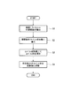
以下に、本実施形態のめっき用銅材の製造方法について、図3のフロー図を用いて説明する。
まず、銅の純度が99.96%以上、酸素量が20ppm以下の低酸素銅又は無酸素銅からなり、直径rが1.5mm≦r≦5mmの範囲内とされた銅線を製出する(銅線製出工程S1)。このような銅線を効率的に製出するには、例えばベルトホイール式連続鋳造機を用いて長尺の棒状鋳塊を連続的に製出しながら、この棒状鋳塊を連続圧延して銅荒引線を製造する。次いで、冷間伸線工程によって銅荒引線を硬銅線に加工する。このとき、銅線(硬銅線)の引張強度TSがTS≧350MPaとなるように、さらに好ましくはTS≧400MPaとなるように、圧延条件、熱処理条件、冷間伸線工程条件等が設定される。
まず、銅の純度が99.96%以上、酸素量が20ppm以下の低酸素銅又は無酸素銅からなり、直径rが1.5mm≦r≦5mmの範囲内とされた銅線を製出する(銅線製出工程S1)。このような銅線を効率的に製出するには、例えばベルトホイール式連続鋳造機を用いて長尺の棒状鋳塊を連続的に製出しながら、この棒状鋳塊を連続圧延して銅荒引線を製造する。次いで、冷間伸線工程によって銅荒引線を硬銅線に加工する。このとき、銅線(硬銅線)の引張強度TSがTS≧350MPaとなるように、さらに好ましくはTS≧400MPaとなるように、圧延条件、熱処理条件、冷間伸線工程条件等が設定される。
次に、直径rが1.5mm≦r≦5mmの範囲内とされた銅線を、コイル成形機に供給する(銅線供給工程S2)。
コイル成形機においては、銅線を送りながら順次曲げ加工を施してコイル体を成形する(コイル成形工程S3)。
そして、所定長さの銅線を加工した時点で銅線を切断する(切断工程S4)。
このようにして、本実施形態のめっき用銅材10が製出される。
コイル成形機においては、銅線を送りながら順次曲げ加工を施してコイル体を成形する(コイル成形工程S3)。
そして、所定長さの銅線を加工した時点で銅線を切断する(切断工程S4)。
このようにして、本実施形態のめっき用銅材10が製出される。
以下に、本実施形態のめっき用銅材10を用いた銅めっき材の製造方法について説明する。
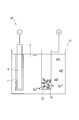
図4は、本実施形態のめっき用銅材10を溶解性陽極として使用した例(第1の実施形態)を示す。
このめっき装置20は、硫酸液等からなるめっき液2が貯留されるめっき槽21と、銅めっき膜7が形成される被めっき材6と、本実施形態のめっき用銅材10が収容されるバスケット23とを備えている。なお、バスケット23は、Tiなどの耐食性材料で構成される。
図4は、本実施形態のめっき用銅材10を溶解性陽極として使用した例(第1の実施形態)を示す。
このめっき装置20は、硫酸液等からなるめっき液2が貯留されるめっき槽21と、銅めっき膜7が形成される被めっき材6と、本実施形態のめっき用銅材10が収容されるバスケット23とを備えている。なお、バスケット23は、Tiなどの耐食性材料で構成される。
ここで、被めっき材6が陰極とされ、バスケット23に収容されためっき用銅材10が溶解性陽極とされており、これら陰極と陽極とに通電を行う。
すると、バスケット23内に収容されためっき用銅材10がめっき液2中に溶解し、これにより、めっき液2中に銅イオンが供給される。この銅イオンが、陰極(被めっき材6)の表面に電析し、被めっき材6の表面に銅めっき膜7が形成される。
この場合、銅めっき膜7の形成が進むにつれて、めっき用銅材10が徐々に溶解して減少するため、適宜、めっき用銅材10をバスケット23内に供給する手段を設けることが好ましい。
すると、バスケット23内に収容されためっき用銅材10がめっき液2中に溶解し、これにより、めっき液2中に銅イオンが供給される。この銅イオンが、陰極(被めっき材6)の表面に電析し、被めっき材6の表面に銅めっき膜7が形成される。
この場合、銅めっき膜7の形成が進むにつれて、めっき用銅材10が徐々に溶解して減少するため、適宜、めっき用銅材10をバスケット23内に供給する手段を設けることが好ましい。
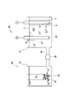
次に、図5は、本実施形態のめっき用銅材10を用いて銅イオンを供給するとともに、不溶解性陽極を用いて銅めっきを行う例(第2の実施形態)を示す。
このめっき装置30は、硫酸液等からなるめっき液2が貯留されるめっき槽31と、銅めっき膜7が形成される被めっき材6と、酸化イリジウム等からなる不溶性陽極33と、めっき液2中に銅イオンを供給する銅イオン供給装置40と、この銅イオン供給装置40とめっき槽31とを連絡する連絡路37とを備えている。
このめっき装置30は、硫酸液等からなるめっき液2が貯留されるめっき槽31と、銅めっき膜7が形成される被めっき材6と、酸化イリジウム等からなる不溶性陽極33と、めっき液2中に銅イオンを供給する銅イオン供給装置40と、この銅イオン供給装置40とめっき槽31とを連絡する連絡路37とを備えている。
銅イオン供給装置40は、めっき液2が貯留されるイオン発生槽41と、このイオン発生槽41を陰極室41Aと陽極室41Bとに区画する水素イオン交換膜45と、陰極室41A内に設けられた陰極部44と、陽極室41Bに配設され、本実施形態のめっき用銅材10を収容するバスケット43とを備えている。
ここで、銅イオン供給装置40とめっき槽31とを連絡する連絡路37は、イオン発生槽41の陽極室41Bに接続されている。
ここで、銅イオン供給装置40とめっき槽31とを連絡する連絡路37は、イオン発生槽41の陽極室41Bに接続されている。
銅イオン供給装置40においては、バスケット43及びバスケット43内に収容されためっき用銅材10を陽極とし、陰極室41Aの陰極部44との間で通電を行う。すると、めっき用銅材10がめっき液2内に溶解して銅イオンがめっき液2中に供給されることになる。ここで、陽極室41B内に存在する水素イオンは、水素イオン交換膜45を通過して陰極室41A内に侵入し、陰極部44の表面から水素ガスとして外部に放出される。
陽極室41Bにおいて銅イオンが供給されためっき液2は、連絡路37を通じてめっき槽31内に供給される。このめっき槽31においては、不溶性陽極33と陰極である被めっき材6とに通電を行うことにより、めっき液2中の銅イオンが陰極(被めっき材6)の表面に電析し、被めっき材6の表面に銅めっき膜7が形成される。
本実施形態のめっき用銅材10によれば、銅線が螺旋状に巻かれたコイル体からなるので、銅線の外周面がコイル体の外周側及び内周側に露出されることになり、表面積Sと体積Vとの比S/Vが大きくなる。このため、硫酸液等のめっき液2中に銅が溶解しやすく、めっき液2中に銅イオンを効率的に供給できる。また、めっき用銅材10の内周面でもめっき液2と接触することから、複数のめっき用銅材10をバスケット23、43に装入したとしても、円筒状をなすめっき用銅材10の内周面(内周側)から銅が溶解される。このため、めっき液2中への銅イオンの供給をさらに効率良く行うことができる。
また、本実施形態では、銅線の外径rが、1.5mm≦r≦5mmの範囲内に設定されており、さらに具体的には、2.6mm≦r≦3.2mmの範囲内に設定されているので、銅線の剛性が確保される。このため、複数のめっき用銅材10が重なり合った場合であっても、めっき用銅材10が潰れるように変形せず、めっき用銅材10の内周側でめっき液2と接触させて溶解できる。また、表面積Sと体積Vとの比S/Vを大きくすることができ、効率的にめっき用銅材10を溶解できる。
また、外径rが2.6mm≦r≦3.2mmの範囲内に設定された銅線は、前述したようにベルトホイール式連続鋳造機を用いた連続鋳造圧延手段及び冷間伸線工程によって良好に製出することが可能なため、本実施形態のめっき用銅材10を効率良く製出できる。
また、外径rが2.6mm≦r≦3.2mmの範囲内に設定された銅線は、前述したようにベルトホイール式連続鋳造機を用いた連続鋳造圧延手段及び冷間伸線工程によって良好に製出することが可能なため、本実施形態のめっき用銅材10を効率良く製出できる。
しかも、銅線の引張強度TSが、TS≧350MPa、さらに好ましくはTS≧400MPaとされているので、銅線の剛性が確保される。このため、複数のめっき用銅材10が重なり合った場合であっても、めっき用銅材10が潰れるように変形せず、めっき用銅材10の内周側でめっき液2と接触させて溶解することが可能となる。また、比較的容易に、銅線を螺旋状に巻いてコイル体に成形できる。
さらに、本実施形態においては、巻かれた銅線のピッチPは、銅線の直径rに対して、(r+0.1)mm≦P≦(3×r)mmの範囲内に設定され、具体的には、1.6mm≦P≦15mmの範囲内に設定されている。このため、隣接する銅線同士の隙間から硫酸液等のめっき液2がめっき用銅材10の内周側に導入され、めっき用銅材10の溶解が促進される。また、他のめっき用銅材10の銅線が、前記隙間に挟まることがなく、めっき用銅材10同士が絡み合わないため、めっき用銅材10の溶解を促進できる。
また、本実施形態のめっき用銅材10の製造方法によれば、銅線を連続的にコイル成形機に導入して、コイル体からなるめっき用銅材10を成形する。このため、本実施形態のめっき用銅材10を効率良く製出できる。さらに、本実施形態では、ベルトホイール式連続鋳造機を用いて長尺の棒状鋳塊を連続的に製出するとともに、この棒状鋳塊を連続圧延する連続鋳造圧延手段を用いている。このため、高品位な銅線を低コストで効率良く製出でき、本実施形態のめっき用銅材10をさらに効率良く製出できる。
さらに、本実施形態のめっき用銅材10を用いた銅めっき材の製造方法の例(第1,2の実施形態)では、めっき用銅材10がめっき液2中に効率良く溶解して、めっき液2中に銅イオンが供給される。このため、銅めっきを効率的に行うことができる。
また、図5に示すように、銅イオン供給装置40を用いた場合には、不溶解性陽極33を用いた銅めっき材の製造方法においても、本実施形態のめっき用銅材10を使用できる。
また、図5に示すように、銅イオン供給装置40を用いた場合には、不溶解性陽極33を用いた銅めっき材の製造方法においても、本実施形態のめっき用銅材10を使用できる。
また、本実施形態のめっき用銅材10を用いた銅めっき材の製造方法の例(第1,2の実施形態)では、電解法によってめっき用銅材10を溶解している。従来では、電解法により銅材を溶解した場合、めっき用銅材10の表面にブラックフィルムが厚く成長してアノードスライムが発生しやすかった。しかしながら、本実施形態では、めっき用銅材10が、銅線が螺旋状に巻かれたコイル体からなるため、めっき液2がめっき用銅材10の内周側を通過でき、めっき液2の流速が確保される。これにより、めっき用銅材10の周囲において2価銅イオンの濃度が必要以上に高くなることがない。このため、銅粉の発生が抑えられ、ブラックフィルムの成長やアノードスライムの生成が抑制される。
次に、図6は、本実施形態のめっき用銅材10を化学反応によって溶解して銅イオンを供給するとともに、不溶解性陽極を用いて銅めっきを行う例(第3の実施形態)を示す。
このめっき装置90は、硫酸銅液、硫酸鉄液、及び硫酸液等からなるめっき液2が貯留されるめっき槽91と、銅めっき膜7が形成される被めっき材6と、酸化イリジウム等からなる不溶性陽極93と、めっき液2に銅イオンを供給する銅イオン供給装置96と、この銅イオン供給装置96とめっき槽91とを連絡する連絡路94と、めっき液2を循環させるポンプ95とを備えている。
銅イオン供給装置96は、めっき液2が貯留されるイオン発生槽97と、このイオン発生槽97内のめっき液2に浸漬されるバスケット98とを備えている。
なお、この銅めっき材の製造方法の一例(第3の実施形態)では、他の例とは異なり、めっき液2として、硫酸鉄が溶解されてFe2+イオン及びFe3+イオンを含むめっき液を使用する。
このめっき装置90は、硫酸銅液、硫酸鉄液、及び硫酸液等からなるめっき液2が貯留されるめっき槽91と、銅めっき膜7が形成される被めっき材6と、酸化イリジウム等からなる不溶性陽極93と、めっき液2に銅イオンを供給する銅イオン供給装置96と、この銅イオン供給装置96とめっき槽91とを連絡する連絡路94と、めっき液2を循環させるポンプ95とを備えている。
銅イオン供給装置96は、めっき液2が貯留されるイオン発生槽97と、このイオン発生槽97内のめっき液2に浸漬されるバスケット98とを備えている。
なお、この銅めっき材の製造方法の一例(第3の実施形態)では、他の例とは異なり、めっき液2として、硫酸鉄が溶解されてFe2+イオン及びFe3+イオンを含むめっき液を使用する。
銅イオン供給装置96においては、バスケット98内に本実施形態のめっき用銅材10が収容され、めっき液2に浸漬される。すると、めっき用銅材10は、以下の化学反応によりめっき液2内に溶解して、銅イオンがめっき液2中に供給されることになる。
Cu + 2Fe3+ → Cu2+ + 2Fe2+
イオン供給槽97において銅イオンが供給されためっき液2は、連絡路94を通じてめっき槽91に供給される。このめっき槽91においては、不溶性陽極93と陰極である被めっき材6とに通電を行うことにより、めっき液2中の銅イオンが被めっき材6の表面に電析し、被めっき材6の表面に銅めっき膜が形成される。
Cu + 2Fe3+ → Cu2+ + 2Fe2+
イオン供給槽97において銅イオンが供給されためっき液2は、連絡路94を通じてめっき槽91に供給される。このめっき槽91においては、不溶性陽極93と陰極である被めっき材6とに通電を行うことにより、めっき液2中の銅イオンが被めっき材6の表面に電析し、被めっき材6の表面に銅めっき膜が形成される。
この本実施形態のめっき用銅材10を用いた銅めっき材の製造方法の例(第3の実施形態)によれば、めっき用銅材10が、銅線が螺旋状に巻かれたコイル体からなるので、銅線の外周面がコイル体の外周側及び内周側に露出されることになり、表面積Sと体積Vとの比S/Vが大きくなる。
ここで、第3の実施形態では、鉄イオンの酸化還元反応を利用してめっき用銅材10を溶解しているので、溶解速度は化学反応が起る面積に大きく依存する。よって、表面積Sと体積Vとの比S/Vが大きくなることで、溶解速度を大幅に向上させることが可能となる。さらに、めっき用銅材10が、銅線が螺旋状に巻かれたコイル体からなることから、めっき用銅材10表面におけるめっき液2の流れが円滑となる。このため、銅及び鉄イオンの供給が迅速に行われ、銅の溶解速度がさらに向上する。これは、銅の溶解反応は、銅及び鉄イオンの供給速度に支配される拡散律速反応であるからである。
ここで、第3の実施形態では、鉄イオンの酸化還元反応を利用してめっき用銅材10を溶解しているので、溶解速度は化学反応が起る面積に大きく依存する。よって、表面積Sと体積Vとの比S/Vが大きくなることで、溶解速度を大幅に向上させることが可能となる。さらに、めっき用銅材10が、銅線が螺旋状に巻かれたコイル体からなることから、めっき用銅材10表面におけるめっき液2の流れが円滑となる。このため、銅及び鉄イオンの供給が迅速に行われ、銅の溶解速度がさらに向上する。これは、銅の溶解反応は、銅及び鉄イオンの供給速度に支配される拡散律速反応であるからである。
以上、本発明の実施形態のめっき用銅材及びめっき用銅材の製造方法、並びに、本実施形態のめっき用銅材を用いた銅めっき材の製造方法(第1~3の実施形態)について説明したが、本発明はこれに限定されることはなく、その発明の技術的思想を逸脱しない範囲で適宜変更可能である。
例えば、めっき用銅材として、低酸素銅又は無酸素銅からなる銅線をコイル成形することによって製出されたものを例示して説明したが、これに限定されることはない。リンを0.03質量%以上0.08質量%以下含有するリン含有銅合金からなる銅線をコイル成形して製出されたものでもよい。さらに、めっき用銅材は、タフピッチ銅(TPC)やガス成分を除いた純度が99.999%以上の高純度銅(5N銅,6N銅等)で構成されていてもよい。
例えば、めっき用銅材として、低酸素銅又は無酸素銅からなる銅線をコイル成形することによって製出されたものを例示して説明したが、これに限定されることはない。リンを0.03質量%以上0.08質量%以下含有するリン含有銅合金からなる銅線をコイル成形して製出されたものでもよい。さらに、めっき用銅材は、タフピッチ銅(TPC)やガス成分を除いた純度が99.999%以上の高純度銅(5N銅,6N銅等)で構成されていてもよい。
特に、電解によってめっき用銅材を溶解する場合には、前述のように、リンを含むリン含有銅合金からなるめっき用銅材を用いることが好ましい。リン含有銅合金からなるめっき用銅材を電解により溶解すると、めっき用銅材の表面に、ブラックフィルムが均一に薄く形成される。このブラックフィルムによって不均化反応が抑制されて不動態化が防止され、めっき用銅材を良好に溶解できる。
一方、化学反応によってめっき用銅材を溶解する場合には、ブラックフィルムを利用する必要がないため、無酸素銅等からなるめっき用銅材を用いることが好ましい。
一方、化学反応によってめっき用銅材を溶解する場合には、ブラックフィルムを利用する必要がないため、無酸素銅等からなるめっき用銅材を用いることが好ましい。
また、被めっき材6については、特に限定されることはなく、種々の被めっき材に対する銅めっきにおいて、本発明のめっき用銅材を用いることができる。例えば、プリント配線基板への銅めっき、半導体用銅めっき、プラスチック材への銅めっき、鋼板への銅めっき等に用いることができる。
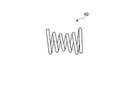
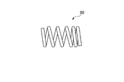
また、本発明のめっき用銅材として、外形が円筒状をなすものを例示して説明したが、これに限定されることはない。例えば、図7に示すように外形が円錐状をなしていてもよい。また図8に示すように中央の径が小さくされたもの、あるいは、図9に示すように中央の径が大きくされたものであってもよい。また、図10に示すように、巻きのピッチPが変化したものであってもよい。
さらに、銅めっきを行うめっき装置の構成は、図4~図6に記載されたものに限定されることはなく、適宜設計変更することができる。
また、めっき用銅材の製造方法として、ベルトホイール式連続鋳造機を用いた連続鋳造圧延手段によって銅線を製出する方法を例示して説明したが、これに限定されることはない。例えば、押出成形等の他の手段によって銅線を製出してもよい。
さらに、図5に示す銅イオン供給装置40では、電解方法によって銅イオンを生成させたが、銅イオンの生成方法は、これに限定されることはない。例えば、銅材を熱濃硫酸(例えば、温度70℃、濃度98%)に浸漬溶解させる方法などを用いて銅イオンを生成してもよい。
また、めっき用銅材の製造方法として、ベルトホイール式連続鋳造機を用いた連続鋳造圧延手段によって銅線を製出する方法を例示して説明したが、これに限定されることはない。例えば、押出成形等の他の手段によって銅線を製出してもよい。
さらに、図5に示す銅イオン供給装置40では、電解方法によって銅イオンを生成させたが、銅イオンの生成方法は、これに限定されることはない。例えば、銅材を熱濃硫酸(例えば、温度70℃、濃度98%)に浸漬溶解させる方法などを用いて銅イオンを生成してもよい。
また、図6に示す銅イオン供給装置96では、鉄イオンの酸化還元反応を利用してめっき用銅材10を溶解する方法を例示して説明したが、銅イオンの生成方法は、これに限定されることはない。例えば、空気もしくは酸素ガスをめっき液中に供給し、銅を酸素で酸化・溶解させる方法等で銅イオンを生成してもよい。
さらに、バスケット98内にめっき用銅材10を収容して、イオン発生槽97内のめっき液2に浸漬させる方法を例示して説明したが、めっき用銅材10の浸漬方法は、これに限定されることはない。例えば、めっき用銅材10を直接イオン発生槽97のめっき液2中に浸漬させてもよい。
さらに、バスケット98内にめっき用銅材10を収容して、イオン発生槽97内のめっき液2に浸漬させる方法を例示して説明したが、めっき用銅材10の浸漬方法は、これに限定されることはない。例えば、めっき用銅材10を直接イオン発生槽97のめっき液2中に浸漬させてもよい。
(実施例1)
本発明のめっき用銅材及び従来使用されているめっき用銅ボールについて、表面積Sと体積Vとの比S/Vを算出した結果を表1に示す。
従来例は、一般的に広く使用されている直径11mmのめっき用銅ボールである。
本発明例のめっき用銅材は、直径2.6mmの銅線を、従来例のめっき用銅ボールと同じ体積となる長さで切断し、コイル状に巻いて作製した。
本発明のめっき用銅材及び従来使用されているめっき用銅ボールについて、表面積Sと体積Vとの比S/Vを算出した結果を表1に示す。
従来例は、一般的に広く使用されている直径11mmのめっき用銅ボールである。
本発明例のめっき用銅材は、直径2.6mmの銅線を、従来例のめっき用銅ボールと同じ体積となる長さで切断し、コイル状に巻いて作製した。

本発明例においては、従来例と比較して、表面積Sと体積Vとの比S/Vが約2.85倍であることが確認された。このため、めっき液との接触面積が増大し、めっき液中への溶解が促進されることが期待される。
(実施例2)
次に、本発明例のめっき用銅材及び従来使用されている従来例のめっき用銅ボールを、化学反応によって溶解した場合の溶解速度について比較評価した。
実施例1の本発明例のめっき用銅材及び従来例のめっき用銅ボールを、それぞれ30個、Tiバスケット198内に収容した。
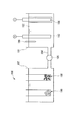
図11に示すように、本発明例のめっき用銅材及び従来例のめっき用銅ボールがそれぞれ収容されたTiバスケット198をイオン発生槽197に浸漬した。このイオン発生槽197と連絡路194によって接続されためっき槽191には、カソード板106と、酸化イリジウム等からなる不溶性陽極193とを浸漬した。
次に、本発明例のめっき用銅材及び従来使用されている従来例のめっき用銅ボールを、化学反応によって溶解した場合の溶解速度について比較評価した。
実施例1の本発明例のめっき用銅材及び従来例のめっき用銅ボールを、それぞれ30個、Tiバスケット198内に収容した。
図11に示すように、本発明例のめっき用銅材及び従来例のめっき用銅ボールがそれぞれ収容されたTiバスケット198をイオン発生槽197に浸漬した。このイオン発生槽197と連絡路194によって接続されためっき槽191には、カソード板106と、酸化イリジウム等からなる不溶性陽極193とを浸漬した。
めっき液102として、以下の組成のものを使用し、めっき液量を30L、めっき液温度を21~25℃とした。
CuSO4・5H2O :140g/L
FeSO4・7H2O :20g/L
H2SO4 :100g/L
Cl- :50ppm
CuSO4・5H2O :140g/L
FeSO4・7H2O :20g/L
H2SO4 :100g/L
Cl- :50ppm
なお、予め試験開始前(本発明例のめっき用銅材及び従来例のめっき用銅ボールを浸漬する前)に電解を行い、不溶性陽極193上でFe2+→ Fe3+ + e-の反応を起こし、Fe3+を生成した。このようにして、めっき液中のFe3+初期濃度を0.003mol/L(ORP計199によって測定した酸化還元電位より算出)に調整した。
次いで、本発明例のめっき用銅材及び従来例のめっき用銅ボールがそれぞれ収容されたTiバスケット198をイオン発生槽197に浸漬した状態で、10Aの電流を17時間流して電解を行った。そして、電解前後のめっき用銅材の重量変化を測定した。
その結果、従来例では、重量減少量が10.7gであったのに対して、本発明例では、重量減少量が35.7gであった。このように、本発明例では、従来例に比べて3.34倍の量が溶解したことが確認された。
次いで、本発明例のめっき用銅材及び従来例のめっき用銅ボールがそれぞれ収容されたTiバスケット198をイオン発生槽197に浸漬した状態で、10Aの電流を17時間流して電解を行った。そして、電解前後のめっき用銅材の重量変化を測定した。
その結果、従来例では、重量減少量が10.7gであったのに対して、本発明例では、重量減少量が35.7gであった。このように、本発明例では、従来例に比べて3.34倍の量が溶解したことが確認された。
ここで、実施例1に記載されているように、本発明例においては、表面積Sと体積Vとの比S/Vが、従来例の約2.85倍であるが、溶解量は3.34倍となっている。これは、表面積が増加した効果に加えて、めっき液の流れが促進された(めっき液が滞留し難い)ことによって、銅及び鉄イオンの供給が円滑に行われたためであると推測される。
このように、化学反応を利用してめっき用銅材を溶解する場合において、本発明のめっき用銅材は、特に有効である。
このように、化学反応を利用してめっき用銅材を溶解する場合において、本発明のめっき用銅材は、特に有効である。
(実施例3)
次に、本発明例のめっき用銅材及び従来使用されている従来例のめっき用銅ボールを、電解によって溶解した場合のアノードスライムの発生量について比較評価した。
実施例1の本発明例のめっき用銅材又は従来例のめっき用銅ボールをTiバスケット198内に30個収容した。
図12に示すように、本発明例のめっき用銅材又は従来例のめっき用銅ボールを収容したTiバスケット123とカソード板106とをめっき液102に浸漬した。そして、2.5Aの電流を通電して電解を行い、本発明例のめっき用銅材又は従来例のめっき用銅ボールを溶解した。そして、1週間電解を行った後のスライム量を測定した。
次に、本発明例のめっき用銅材及び従来使用されている従来例のめっき用銅ボールを、電解によって溶解した場合のアノードスライムの発生量について比較評価した。
実施例1の本発明例のめっき用銅材又は従来例のめっき用銅ボールをTiバスケット198内に30個収容した。
図12に示すように、本発明例のめっき用銅材又は従来例のめっき用銅ボールを収容したTiバスケット123とカソード板106とをめっき液102に浸漬した。そして、2.5Aの電流を通電して電解を行い、本発明例のめっき用銅材又は従来例のめっき用銅ボールを溶解した。そして、1週間電解を行った後のスライム量を測定した。
めっき液102として、以下の組成のものを使用し、めっき液量を5L、めっき液温度を21~25℃とした。
CuSO4・5H2O :75g/L
H2SO4 :180g/L
Cl- :50ppm
ジスルフィド化合物を含む添加剤 :1.5mL/L
ポリエチレングリコールを含む添加剤 :15mL/L
CuSO4・5H2O :75g/L
H2SO4 :180g/L
Cl- :50ppm
ジスルフィド化合物を含む添加剤 :1.5mL/L
ポリエチレングリコールを含む添加剤 :15mL/L
1週間電解を行った後のアノードスライム量は、従来例では2.53gであったのに対して、本発明例では1.08gであった。
このように、めっき用銅材を電解法によって溶解する場合であっても、本発明のコイル状のめっき用銅材を用いることによって、アノードスライムの発生量を抑制することが可能であることが確認された。
このように、めっき用銅材を電解法によって溶解する場合であっても、本発明のコイル状のめっき用銅材を用いることによって、アノードスライムの発生量を抑制することが可能であることが確認された。
本発明のめっき用銅材は、銅めっき材の製造方法に用いた場合、硫酸液等からなるめっき液中に銅イオンを効率的に供給でき、かつ、銅粉の発生を抑制できる。これにより、効率良くめっきを行うことができる。このため、本発明は、例えば、プリント配線基板への銅めっき、半導体用銅めっき、プラスチック材への銅めっき、鋼板への銅めっき等に好適に適用できる。
2 めっき液、6 被めっき材、10、50、60、70、80 めっき用銅材、20、30、90 めっき装置、21、31、91 めっき槽、23、43 バスケット、33 不溶解性陽極、40、90 銅イオン供給装置。
Claims (7)
- 銅線が螺旋状に巻かれたコイル体からなり、
めっき液中に銅イオンを供給する際に用いられることを特徴とするめっき用銅材。 - 前記銅線の外径が、1.5mm以上5mm以下であることを特徴とする請求項1に記載のめっき用銅材。
- 前記銅線の引張強度が、350MPa以上であることを特徴とする請求項1に記載のめっき用銅材。
- 銅線を供給する銅線供給工程と、供給された前記銅線をコイル状に巻くコイル成形工程と、所定長さのコイル体を成形した後に前記銅線を切断する切断工程とを備えていることを特徴とする請求項1に記載のめっき用銅材の製造方法。
- めっき液が貯留されためっき槽内に、被めっき材を陰極として浸漬するとともに、前記めっき槽内に溶解性陽極を浸漬する工程と、
前記溶解性陽極及び前記陰極に通電して前記被めっき材の表面に銅を電析させる工程を有し、
前記溶解性陽極として請求項1に記載のめっき用銅材を前記めっき槽内に浸漬することを特徴とする銅めっき材の製造方法。 - めっき液が貯留されためっき槽内に、被めっき材を陰極として浸漬するとともに、前記めっき槽内に不溶性陽極を浸漬する工程と、
前記不溶性陽極及び前記陰極に通電して前記被めっき材の表面に銅を電析させる工程を有し、
前記めっき液は、請求項1に記載のめっき用銅材を溶解することにより銅イオンを供給して生成され、前記めっき液を前記めっき槽に供給することを特徴とする銅めっき材の製造方法。 - めっき液が貯留されためっき槽内に、被めっき材を陰極として浸漬するとともに、前記めっき槽内に不溶性陽極を浸漬する工程と、
前記不溶性陽極及び前記陰極に通電して前記被めっき材の表面に銅を電析させる工程を有し、
前記めっき液は、請求項1に記載のめっき用銅材を化学反応によって溶解することにより銅イオンを供給して生成され、前記めっき液を前記めっき槽に供給することを特徴とする銅めっき材の製造方法。
Priority Applications (1)
| Application Number | Priority Date | Filing Date | Title |
|---|---|---|---|
| CN201080003609.4A CN102257187B (zh) | 2009-01-08 | 2010-01-05 | 电镀用铜材和电镀用铜材的制造方法及镀铜材的制造方法 |
Applications Claiming Priority (6)
| Application Number | Priority Date | Filing Date | Title |
|---|---|---|---|
| JP2009002624 | 2009-01-08 | ||
| JP2009-002624 | 2009-01-08 | ||
| JP2009034611 | 2009-02-17 | ||
| JP2009-034611 | 2009-02-17 | ||
| JP2009-241404 | 2009-10-20 | ||
| JP2009241404A JP5402517B2 (ja) | 2009-01-08 | 2009-10-20 | めっき用銅材及びめっき用銅材の製造方法、並びに、銅めっき材の製造方法 |
Publications (1)
| Publication Number | Publication Date |
|---|---|
| WO2010079735A1 true WO2010079735A1 (ja) | 2010-07-15 |
Family
ID=42316500
Family Applications (1)
| Application Number | Title | Priority Date | Filing Date |
|---|---|---|---|
| PCT/JP2010/000014 Ceased WO2010079735A1 (ja) | 2009-01-08 | 2010-01-05 | めっき用銅材及びめっき用銅材の製造方法、並びに銅めっき材の製造方法 |
Country Status (3)
| Country | Link |
|---|---|
| JP (1) | JP5402517B2 (ja) |
| CN (1) | CN102257187B (ja) |
| WO (1) | WO2010079735A1 (ja) |
Cited By (1)
| Publication number | Priority date | Publication date | Assignee | Title |
|---|---|---|---|---|
| JP2011219868A (ja) * | 2010-04-12 | 2011-11-04 | Chang Chun Petrochemical Co Ltd | 電解銅箔に使用される銅材及びその使用方法 |
Families Citing this family (5)
| Publication number | Priority date | Publication date | Assignee | Title |
|---|---|---|---|---|
| JP2014173179A (ja) * | 2013-03-12 | 2014-09-22 | Mitsubishi Materials Corp | めっき用銅粒 |
| JP2017210644A (ja) * | 2016-05-24 | 2017-11-30 | メルテックス株式会社 | 溶解性銅陽極、電解銅めっき装置、電解銅めっき方法、及び酸性電解銅めっき液の保存方法 |
| CN107675202A (zh) * | 2017-09-27 | 2018-02-09 | 广西七色珠光材料股份有限公司 | 颜料水解包膜反应器 |
| CN109930184B (zh) * | 2019-03-22 | 2020-06-30 | 苏州昕皓新材料科技有限公司 | 线圈的制备方法及线圈 |
| CN112962137B (zh) * | 2021-02-01 | 2021-10-01 | 广东嘉元科技股份有限公司 | 一种铜丝螺旋截断后送料溶铜罐 |
Citations (2)
| Publication number | Priority date | Publication date | Assignee | Title |
|---|---|---|---|---|
| JPS5432138A (en) * | 1977-08-15 | 1979-03-09 | Cities Service Co | Anode and anode basket and method of holding anode |
| JP2006214008A (ja) * | 2002-07-17 | 2006-08-17 | Dainippon Screen Mfg Co Ltd | メッキ装置に用いるカートリッジおよび銅溶解タンク |
-
2009
- 2009-10-20 JP JP2009241404A patent/JP5402517B2/ja not_active Expired - Fee Related
-
2010
- 2010-01-05 CN CN201080003609.4A patent/CN102257187B/zh not_active Expired - Fee Related
- 2010-01-05 WO PCT/JP2010/000014 patent/WO2010079735A1/ja not_active Ceased
Patent Citations (2)
| Publication number | Priority date | Publication date | Assignee | Title |
|---|---|---|---|---|
| JPS5432138A (en) * | 1977-08-15 | 1979-03-09 | Cities Service Co | Anode and anode basket and method of holding anode |
| JP2006214008A (ja) * | 2002-07-17 | 2006-08-17 | Dainippon Screen Mfg Co Ltd | メッキ装置に用いるカートリッジおよび銅溶解タンク |
Cited By (1)
| Publication number | Priority date | Publication date | Assignee | Title |
|---|---|---|---|---|
| JP2011219868A (ja) * | 2010-04-12 | 2011-11-04 | Chang Chun Petrochemical Co Ltd | 電解銅箔に使用される銅材及びその使用方法 |
Also Published As
| Publication number | Publication date |
|---|---|
| JP2010216003A (ja) | 2010-09-30 |
| CN102257187A (zh) | 2011-11-23 |
| CN102257187B (zh) | 2014-01-15 |
| JP5402517B2 (ja) | 2014-01-29 |
Similar Documents
| Publication | Publication Date | Title |
|---|---|---|
| Lu et al. | Advances in electrolytic copper foils: fabrication, microstructure, and mechanical properties | |
| JP5402517B2 (ja) | めっき用銅材及びめっき用銅材の製造方法、並びに、銅めっき材の製造方法 | |
| JP4846740B2 (ja) | めっき物の製造方法及び電気めっき方法 | |
| TWI522497B (zh) | 電鍍銅用含磷銅陽極,其製造方法及電鍍銅之方法 | |
| US20050079280A1 (en) | Electroless copper plating solution, electroless copper plating process and production process of circuit board | |
| JP6823891B2 (ja) | 高強度・高導電率電鋳銅合金及び製造方法 | |
| EP0337517A1 (en) | Metal fibers obtained by bundled drawing | |
| TWI683931B (zh) | 電解鍍銅用陽極及使用其之電解鍍銅裝置 | |
| CN102844472A (zh) | 电解铜电镀用高纯度铜阳极、其制造方法及电解铜电镀方法 | |
| JP2014173179A (ja) | めっき用銅粒 | |
| JP2011046973A (ja) | 電気銅めっき方法および電気銅めっき製品 | |
| EP4317537A1 (en) | Method for removing ferric ions from sulfate-based iron electroplating solution | |
| WO2016104530A1 (ja) | コイル導体の製造方法、及びその方法を用いて製造したコイル導体を備えた誘導コイル | |
| JP5575020B2 (ja) | 金属の電解採取方法 | |
| KR102297887B1 (ko) | 황산계 철 전기도금용액의 제2철 이온 제거 방법 | |
| KR101726092B1 (ko) | 철계 전해액 내의 제이철 이온 농도 제어 방법 및 장치 | |
| JP3959680B2 (ja) | アルミニウム電解コンデンサ陽極箔のエッチング方法 | |
| US10629917B2 (en) | Separator for fuel cells, fuel cell, fuel cell stack, and method of manufacturing separator for fuel cells | |
| JP2022007926A (ja) | 電解二酸化マンガン製造用陰極 | |
| JP6517501B2 (ja) | ストライク銅めっき液およびストライク銅めっき方法 | |
| JP2003105581A (ja) | スズ合金の電解析出方法及び装置 | |
| CN104718319B (zh) | 具有合金镀层的金属板的制造方法 | |
| JPS5871391A (ja) | 溶接用鋼ワイヤの硫酸銅浴電気めつき方法 | |
| JPH0510440B2 (ja) | ||
| JP2004099950A (ja) | 銅箔の連続電解厚めっき方法及び装置 |
Legal Events
| Date | Code | Title | Description |
|---|---|---|---|
| WWE | Wipo information: entry into national phase |
Ref document number: 201080003609.4 Country of ref document: CN |
|
| 121 | Ep: the epo has been informed by wipo that ep was designated in this application |
Ref document number: 10729155 Country of ref document: EP Kind code of ref document: A1 |
|
| NENP | Non-entry into the national phase |
Ref country code: DE |
|
| 122 | Ep: pct application non-entry in european phase |
Ref document number: 10729155 Country of ref document: EP Kind code of ref document: A1 |