WO2010073702A1 - 無線基地局、無線端末、及びチャネル信号形成方法 - Google Patents
無線基地局、無線端末、及びチャネル信号形成方法 Download PDFInfo
- Publication number
- WO2010073702A1 WO2010073702A1 PCT/JP2009/007254 JP2009007254W WO2010073702A1 WO 2010073702 A1 WO2010073702 A1 WO 2010073702A1 JP 2009007254 W JP2009007254 W JP 2009007254W WO 2010073702 A1 WO2010073702 A1 WO 2010073702A1
- Authority
- WO
- WIPO (PCT)
- Prior art keywords
- downlink
- information
- base station
- control information
- antenna ports
- Prior art date
Links
Images


Classifications
-
- H—ELECTRICITY
- H04—ELECTRIC COMMUNICATION TECHNIQUE
- H04L—TRANSMISSION OF DIGITAL INFORMATION, e.g. TELEGRAPHIC COMMUNICATION
- H04L5/00—Arrangements affording multiple use of the transmission path
- H04L5/0001—Arrangements for dividing the transmission path
- H04L5/0014—Three-dimensional division
- H04L5/0023—Time-frequency-space
-
- H—ELECTRICITY
- H04—ELECTRIC COMMUNICATION TECHNIQUE
- H04B—TRANSMISSION
- H04B7/00—Radio transmission systems, i.e. using radiation field
- H04B7/02—Diversity systems; Multi-antenna system, i.e. transmission or reception using multiple antennas
- H04B7/04—Diversity systems; Multi-antenna system, i.e. transmission or reception using multiple antennas using two or more spaced independent antennas
- H04B7/0413—MIMO systems
- H04B7/0456—Selection of precoding matrices or codebooks, e.g. using matrices antenna weighting
-
- H—ELECTRICITY
- H04—ELECTRIC COMMUNICATION TECHNIQUE
- H04B—TRANSMISSION
- H04B7/00—Radio transmission systems, i.e. using radiation field
- H04B7/02—Diversity systems; Multi-antenna system, i.e. transmission or reception using multiple antennas
- H04B7/04—Diversity systems; Multi-antenna system, i.e. transmission or reception using multiple antennas using two or more spaced independent antennas
- H04B7/06—Diversity systems; Multi-antenna system, i.e. transmission or reception using multiple antennas using two or more spaced independent antennas at the transmitting station
- H04B7/0613—Diversity systems; Multi-antenna system, i.e. transmission or reception using multiple antennas using two or more spaced independent antennas at the transmitting station using simultaneous transmission
- H04B7/0615—Diversity systems; Multi-antenna system, i.e. transmission or reception using multiple antennas using two or more spaced independent antennas at the transmitting station using simultaneous transmission of weighted versions of same signal
- H04B7/0619—Diversity systems; Multi-antenna system, i.e. transmission or reception using multiple antennas using two or more spaced independent antennas at the transmitting station using simultaneous transmission of weighted versions of same signal using feedback from receiving side
- H04B7/0636—Feedback format
- H04B7/0639—Using selective indices, e.g. of a codebook, e.g. pre-distortion matrix index [PMI] or for beam selection
-
- H—ELECTRICITY
- H04—ELECTRIC COMMUNICATION TECHNIQUE
- H04L—TRANSMISSION OF DIGITAL INFORMATION, e.g. TELEGRAPHIC COMMUNICATION
- H04L5/00—Arrangements affording multiple use of the transmission path
- H04L5/003—Arrangements for allocating sub-channels of the transmission path
- H04L5/0053—Allocation of signaling, i.e. of overhead other than pilot signals
-
- H—ELECTRICITY
- H04—ELECTRIC COMMUNICATION TECHNIQUE
- H04L—TRANSMISSION OF DIGITAL INFORMATION, e.g. TELEGRAPHIC COMMUNICATION
- H04L5/00—Arrangements affording multiple use of the transmission path
- H04L5/003—Arrangements for allocating sub-channels of the transmission path
- H04L5/0058—Allocation criteria
- H04L5/006—Quality of the received signal, e.g. BER, SNR, water filling
-
- H—ELECTRICITY
- H04—ELECTRIC COMMUNICATION TECHNIQUE
- H04W—WIRELESS COMMUNICATION NETWORKS
- H04W28/00—Network traffic management; Network resource management
- H04W28/02—Traffic management, e.g. flow control or congestion control
- H04W28/06—Optimizing the usage of the radio link, e.g. header compression, information sizing, discarding information
-
- H—ELECTRICITY
- H04—ELECTRIC COMMUNICATION TECHNIQUE
- H04W—WIRELESS COMMUNICATION NETWORKS
- H04W72/00—Local resource management
- H04W72/20—Control channels or signalling for resource management
- H04W72/23—Control channels or signalling for resource management in the downlink direction of a wireless link, i.e. towards a terminal
-
- H—ELECTRICITY
- H04—ELECTRIC COMMUNICATION TECHNIQUE
- H04W—WIRELESS COMMUNICATION NETWORKS
- H04W28/00—Network traffic management; Network resource management
- H04W28/02—Traffic management, e.g. flow control or congestion control
- H04W28/04—Error control
-
- H—ELECTRICITY
- H04—ELECTRIC COMMUNICATION TECHNIQUE
- H04W—WIRELESS COMMUNICATION NETWORKS
- H04W72/00—Local resource management
- H04W72/04—Wireless resource allocation
-
- H—ELECTRICITY
- H04—ELECTRIC COMMUNICATION TECHNIQUE
- H04W—WIRELESS COMMUNICATION NETWORKS
- H04W88/00—Devices specially adapted for wireless communication networks, e.g. terminals, base stations or access point devices
- H04W88/08—Access point devices
Definitions
- the present invention relates to a radio base station, a radio terminal, and a channel signal forming method.
- OFDMA Orthogonal Frequency Division Multiple Access
- SCH Synchronization Channel
- BCH Broadcast Channel
- the terminal first secures synchronization with the base station by capturing the SCH. Thereafter, the terminal acquires parameters (eg, frequency bandwidth) unique to the base station by reading the BCH information (see Non-Patent Documents 1, 2, and 3).
- the terminal establishes communication with the base station by making a connection request to the base station after the acquisition of the parameters unique to the base station is completed.
- the base station transmits control information to terminals with which communication has been established using PDCCH (Physical Downlink ⁇ ⁇ Control ⁇ CHannel) as necessary.
- PDCCH Physical Downlink ⁇ ⁇ Control ⁇ CHannel
- the terminal performs “blind determination” on the received PDCCH signal. That is, the PDCCH signal includes a CRC (Cyclic Redundancy Check) part, and this CRC part is masked by the terminal ID of the transmission target terminal in the base station. Therefore, the terminal cannot determine whether the received PDCCH signal is a PDCCH signal addressed to itself until it demasks the CRC portion of the received PDCCH signal with the terminal ID of the terminal. In this blind determination, if the CRC calculation is OK as a result of demasking, it is determined that the PDCCH signal is addressed to the own device.
- CRC Cyclic Redundancy Check
- control information transmitted from the base station includes allocation control information including resource information allocated to the terminal by the base station.
- the terminal needs to receive both downlink allocation control information and uplink allocation control information having a plurality of formats.
- a plurality of sizes are defined by the transmission antenna control method and frequency allocation method of the base station, and the terminal determines the format using the difference in size.
- Some downlink allocation control information formats hereinafter simply referred to as “downlink allocation control information”
- uplink allocation control information hereinafter simply referred to as “uplink allocation control information” have the same size. It is transmitted with a PDCCH signal.
- type information for example, 1-bit flag
- the terminal confirms the type information of the allocation control information to determine whether the downlink allocation control information or the uplink allocation is performed. You can tell whether it is control information.
- the PDCCH format when uplink allocation control information is transmitted is PDCCH format 0, and the PDCCH format when downlink allocation control information transmitted with a PDCCH signal having the same size as the uplink allocation control information is transmitted is PDCCH. format1A.
- the information size of the uplink allocation control information determined from the uplink bandwidth may differ from the information size of the downlink allocation control information determined from the downlink bandwidth. Specifically, when the uplink bandwidth is small, the information size of the uplink allocation control information is small, and when the downlink bandwidth is small, the information size of the downlink allocation control information is small. When there is a difference in information size due to the difference in bandwidth as described above, zero information is added to the smaller allocation control information (that is, zero padding is performed), thereby reducing the size of the downlink allocation control information. The size of the uplink allocation control information is made equal. Thereby, the same PDCCH signal size is maintained regardless of whether the content is downlink allocation control information or uplink allocation control information. By adjusting the size of the control information as described above, the number of blind determinations at the receiving terminal is reduced.
- the 3GPP LTE-advanced system (hereinafter sometimes referred to as “LTE-A system”) follows the 3GPP LTE system (hereinafter sometimes referred to as “LTE system”).
- LTE-A system 3GPP LTE-advanced is expected to introduce MIMO (Multi-Input Multi-Output) in uplink communication in order to realize an uplink transmission rate of 500 Mbps or more and to improve uplink frequency utilization efficiency.
- the terminal includes a plurality of transmission antennas, and controls the uplink transmission weight (that is, Precoding Vector) and the number of spatial multiplexing of uplink data (that is, the number of spatial layers) according to an instruction from the base station.
- uplink transmission weight that is, Precoding Vector
- the number of spatial multiplexing of uplink data that is, the number of spatial layers
- non-consecutive allocation For example, OFDM or Clustered DFT-s-OFDMA (see Non-Patent Document 4) is used. Therefore, the LTE-A system adaptively allocates subcarriers with good quality on the frequency axis compared to the conventional LTE that only supports continuous allocation in the frequency domain due to the limitation of SC-FDMA. It is possible to improve the frequency utilization efficiency.
- 3GPP TS 36.211 V8.4.0 “Physical Channels and Modulation” (Release 8), “Sep. 2008 3GPP TS 36.212 V8.4.0, “Multiplexing and channel coding (Release 8),” Sep. 2008 3GPP TS 36.213 V8.4.0, “Physical layer procedures (Release 8),” Sep. 2008 3GPP TSG RAN WG1 # 54bis document R1-083658 “Uplink multiple access schemes for LTE-A” LGE, Sep. 2008
- the information sizes of the uplink allocation control information and the downlink allocation control information are substantially equal for the above-described format pair. Therefore, zero padding is hardly performed.
- the size of the uplink allocation control information is smaller than the size of the downlink allocation control information with respect to the uplink allocation control information having a small size for this pair. A lot of zero information is added until they are equal.
- the size of the downlink allocation control information is equal to the size of the uplink allocation control information for the small size downlink allocation control information for this pair. A lot of zero information is added.
- the zero padding is performed for size adjustment, the zero information itself has no meaning information. That is, since the originally unnecessary signal is included in the allocation control information, the power per information bit that is originally required decreases when the total power is constant.
- An object of the present invention is to perform communication using a downlink band and an uplink band between a radio terminal having N antenna ports (N is a natural number) and a radio base station having M antenna ports (M is a natural number).
- N is a natural number
- M is a natural number
- the radio base station of the present invention communicates with a radio terminal having N (N is a natural number) transmission antenna ports using a downlink band and an uplink band, and is a radio having M (M is a natural number) transmission antenna ports.
- a size control means for adjusting the information size of the control information and the uplink allocation control information is adopted.
- the radio terminal of the present invention communicates with a radio base station having M (M is a natural number) transmission antenna ports using downlink and uplink bands, and is a radio having N (N is a natural number) transmission antenna ports.
- a channel signal reception processing means for receiving and processing a channel signal based on the reference information size, and the determining means is a communication method applied between the own device and the radio base station, The number M of transmission antenna ports of the radio base station, the number N of transmission antenna ports of the own device, the bandwidth of the downlink band, and the bandwidth of the uplink band Based on, a configuration of determining the reference information size.
- the channel signal forming method of the present invention uses a downlink band and an uplink band between a radio terminal having N transmission antenna ports (N is a natural number) and a radio base station having M transmission antenna ports (M is a natural number).
- a channel signal forming method for forming a downlink channel signal used for controlling the received communication comprising: forming a downlink channel signal including downlink allocation control information in the downlink band and uplink allocation control information in the uplink band; and Communication method applied between a radio base station and the radio terminal, the number M of transmission antenna ports of the radio base station, the number N of transmission antenna ports of the radio terminal, the bandwidth of the downlink band, and the uplink band Based on the bandwidth of the downlink allocation control information and the uplink allocation control included in the formed downlink channel signal. Comprising the step of adjusting the information size information.
- communication using downlink and uplink bands is performed between a radio terminal having N transmission antenna ports (N is a natural number) and a radio base station having M transmission antenna ports (M is a natural number).
- N is a natural number
- M is a natural number
- the frequency of size adjustment processing being performed on downlink allocation control information or uplink allocation control information is reduced while preventing an increase in the number of blind determinations at the radio terminal on the receiving side of the downlink control channel signal.
- Diagram for explaining resource notification format for uplink data Diagram for explaining resource notification format
- the block diagram which shows the structure of the base station which concerns on one embodiment of this invention The block diagram which shows the structure of the terminal which concerns on one embodiment of this invention Diagram for explaining operation of base station and terminal Diagram for explaining operation of base station and terminal
- the present inventor first notices that spatial division multiplexing (SDM), directivity control (Precoding Matrix Indicator notification: PMI notification), and frequency discontinuous allocation already exist in the LTE downlink. did. That is, in the downlink of the LTE-A system, it is considered that the same resource notification format for downlink data (Format 1B / 1/2) as the LTE system is used following the LTE system. Further, attention was paid to the fact that the information size of Format 0A / 0B / 0C) is equivalent to the information size of Format 1B / 1/2 to which the communication mode is applied.
- SDM spatial division multiplexing
- PMI notification Precoding Matrix Indicator notification
- the partial set and the other set can be distinguished based on the number of transmission antenna ports of the base station and the number of transmission antenna ports of the terminal.
- downlink allocation control information and uplink allocation control included in the downlink channel signal It has been found that by adjusting the information size of information, it is possible to prevent deterioration in the quality of downlink allocation control information while preventing an increase in the number of blind determinations at the terminal.
- antenna port refers to a logical antenna (antenna group) composed of one or more physical antennas. That is, the antenna port does not necessarily indicate one physical antenna, but may indicate an array antenna or the like composed of a plurality of antennas.
- Non-Patent Document 1 it is not defined how many physical antennas an antenna port is composed of, but is defined as a minimum unit in which a base station can transmit different Reference signals.
- the antenna port may be defined as a minimum unit for multiplying the weight of Precoding vector.
- an “antenna port” and a physical antenna correspond one-to-one.
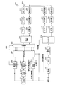
- FIG. 3 is a block diagram showing a configuration of base station 100 according to one embodiment of the present invention.
- the base station 100 includes a control unit 101, a PDCCH generation unit 102, an information size adjustment unit 103, a CRC (Cyclic Redundancy Check) addition unit 104, modulation units 105 and 106, and an SCH / BCH generation unit.
- 107 precoding unit 108, multiplexing unit 109, IFFT unit 110, CP adding unit 111, transmitting RF unit 112, antenna 113, receiving RF unit 114, CP removing unit 115, It has an FFT unit 116, an extraction unit 117, a signal synthesis unit 118, an IDFT unit 119, and a data reception unit 120.
- the control unit 101 generates control information (including uplink allocation control information and downlink allocation control information).
- control unit 101 together with the information size adjustment unit 103, has a function as information size control means for adjusting the information size of downlink allocation control information and uplink allocation control information included in the PDCCH signal. Then, the control unit 101 outputs information corresponding to a communication method applied to the communication partner terminal 200 described later to the information size adjustment unit 103.
- the communication method assumed here is communication that does not involve directivity control by the base station instruction shown in FIG. 1, communication by directivity by the base station instruction, and communication by non-continuous allocation that does not involve directivity control by the base station instruction.
- there are four patterns of non-contiguous assignment communication that are directional communication based on a base station instruction in spatial multiplexing.
- Format1A and Format0 are a pair in communication that does not involve directivity control by a base station instruction.
- Format1B and Format0A are a pair.
- Format1 and Format0B are a pair.
- Format2 and Format0C are a pair.
- the control unit 101 determines the information size of the downlink allocation control information determined from the downlink frequency bandwidth and the corresponding uplink frequency.
- Information size comparison information indicating the size of the information size of the uplink allocation control information determined from the bandwidth is output to the information size adjustment unit 103.
- control unit 101 determines the information size of the downlink allocation control information determined from the downlink frequency bandwidth and the number of antennas of the base station 100 for the pair of Format1B and Format0A and the pair of Format2 and Format0C.
- Information size comparison information indicating the size of the information size of the uplink allocation control information determined from the corresponding uplink frequency bandwidth and the number of antennas of terminal 200 is output to information size adjustment section 103.
- the control unit 101 generates padding control information based on the number of transmission antennas of the base station 100 and the number of transmission antennas of the terminal 200, and outputs the padding control information to the information size adjustment unit 103. Specifically, when the target terminal 200 that transmits the control signal has one transmission antenna, the control unit 101 generates padding control information that does not perform padding for the Format1B and the Format2, and the base station When 100 transmission antennas are provided, padding control information that does not perform padding for the Format0A and the Format0C is generated.
- the PDCCH generation unit 102 receives the control information generated by the control unit 101, and generates a PDCCH signal transmitted in each downlink frequency band based on the control information.
- the information size adjustment unit 103 receives the control information generated by the control unit 101, information size comparison information, and padding control information.
- the information size adjustment unit 103 adjusts the information sizes of the uplink allocation control information and the downlink allocation control information included in the PDCCH signal received from the PDCCH generation unit 102 based on the control information, the information size comparison information, and the padding control information.
- the information size adjusting unit 103 determines whether or not padding is required for the information size adjustment target PDCCH signal based on the padding control information.
- the pair of Format1A and Format0 and the pair of Format1 and Format0B For this, the larger one of the information size of the downlink allocation control information determined from the downlink frequency bandwidth and the information size of the uplink allocation control information determined from the corresponding uplink frequency bandwidth is used as the size adjustment reference. Based on the size adjustment criteria, the information size of the allocation control information is adjusted.
- the pair of Format1B and Format0A and the pair of Format2 and Format0C In contrast, the information size of the downlink allocation control information determined from the downlink frequency bandwidth and the number of antennas of the base station, and the information of the uplink allocation control information determined from the corresponding uplink frequency bandwidth and the number of antennas of the terminal The larger one of the sizes is used as a size adjustment reference, and the information size of the allocation control information is adjusted based on the size adjustment reference.
- the information size adjustment unit 103 determines that it is not necessary to match the sizes of the uplink allocation control information and the downlink allocation control information for the pair of Format0A and Format1B and the pair of Format2 and Format0C based on the padding control information
- the downlink allocation control information ie, Format 1B and Format 2
- the information size of the downlink allocation control information determined from the downlink frequency bandwidth and the number of antennas of the base station 100 is applied as it is
- the uplink allocation control information That is, the size of the uplink allocation control information determined from the frequency bandwidth of the uplink frequency associated with the downlink frequency band and the number of antennas of the terminal is applied as it is to Format 0A and Format 0C. That is, the information size is not adjusted.
- the size adjustment as described above is performed for the pair of Format1A and Format0 and the pair of Format1 and Format0B.
- the information size adjusting unit 103 includes a padding unit (not shown) that adjusts the information size of the control information by adding zero information to the control information.
- This padding section adds zero information to the smaller information size until the information sizes of the downlink allocation control information and the uplink allocation control information become equal. Which of the downlink allocation control information and the uplink allocation control information is to add zero information is determined based on the information size comparison information.
- CRC adding section 104 adds CRC bits to the PDCCH signal whose size has been adjusted by information size adjusting section 103, and masks the CRC bits with a terminal ID. Then, CRC adding section 104 outputs the masked PDCCH signal to modulating section 105.
- Modulating section 105 modulates the PDCCH signal input from CRC adding section 104 and outputs the modulated PDCCH signal to precoding section 108.
- Modulation section 106 modulates input transmission data (downlink data) and outputs the modulated transmission data signal to precoding section 108.
- the SCH / BCH generation unit 107 generates SCH and BCH, and outputs the generated SCH and BCH to the precoding unit 108.
- the precoding unit 108 weights the transmission signal for each terminal for each antenna 113 based on the precoding information instructed from the control unit 101, that is, transmission weight control information.
- This precoding process includes a PDCCH signal input from the modulation unit 105, a data signal input from the modulation unit 106 (that is, a PDSCH signal), and an SCH and BCH input from the SCH / BCH generation unit 107. To be done.
- the weight (Precoding Matrix Indicator: PMI) used for this precoding is negotiated between the terminal side and the base station side in advance for downlink allocation control information and SCH / BCH. Therefore, the terminal 200 receives the downlink control information accordingly. Also, PMI for downlink data is individually notified to each terminal 200 by downlink allocation control information.
- the multiplexing unit 109 multiplexes the PDCCH signal, data signal, SCH, and BCH after precoding processing.
- the multiplexing unit 109 downloads the data signal (PDSCH signal) addressed to the terminal 200 corresponding to the terminal ID. Map to unit band.
- the multiplexing unit 109 maps the PDCCH signal after the precoding process in the resource area allocated for PDCCH.
- the IFFT unit 110 converts the multiplexed signal into a time waveform, and the CP adding unit 111 adds an CP to the time waveform to obtain an OFDM signal.
- the transmission RF unit 112 performs transmission radio processing (up-conversion, digital analog (D / A) conversion, etc.) on the OFDM signal input from the CP adding unit 111 and transmits the signal via the antenna 113. Thereby, an OFDM signal including allocation control information is transmitted.
- transmission radio processing up-conversion, digital analog (D / A) conversion, etc.
- the reception RF unit 114 performs reception radio processing (down-conversion, analog-digital (A / D) conversion, etc.) on the reception radio signal received in the reception band via the antenna 113, and removes the obtained reception signal by CP. Output to the unit 115.
- reception radio processing down-conversion, analog-digital (A / D) conversion, etc.
- CP removing section 115 removes the CP from the received signal, and FFT section 116 converts the received signal after the CP removal into a frequency domain signal.
- the extraction unit 117 extracts uplink data from the frequency domain signal input from the FFT unit 116 based on the uplink allocation control information input from the control unit 101.
- two each of the antenna 113, the reception RF unit 114, the CP removal unit 115, and the FFT unit 116 are provided. Therefore, the extraction unit 117 performs extraction processing for each of the same number of streams as the antenna 113.
- the signal synthesis unit 118 Based on the precoding information used for the uplink data instructed from the control unit 101 (that is, transmission weight control information used in the terminal 200), the signal synthesis unit 118 converts the signal output from the extraction unit 117 into the MRC. Or it synthesize
- An IDFT (Inverse Discrete Fourier Transform) unit 119 converts the extracted signal into a time domain signal and outputs the time domain signal to the data receiving unit 120.
- the data receiving unit 120 decodes the time domain signal input from the IDFT unit 119. Data receiving section 120 then outputs the decoded uplink data as received data.
- FIG. 4 is a block diagram showing a configuration of terminal 200 according to an embodiment of the present invention.
- terminal 200 includes an antenna 201, a reception RF unit 202, a CP removal unit 203, an FFT unit 204, a frame synchronization unit 205, a separation unit 206, a signal synthesis unit 207, and a broadcast signal reception unit. 208, an information size determination unit 209, a PDCCH reception unit 210, a format determination unit 211, a PDSCH reception unit 212, a modulation unit 213, a DFT unit 214, a frequency mapping unit 215, and a precoding ( a precoding unit 216, an IFFT unit 217, a CP adding unit 218, and a transmission RF unit 219.
- precoding a precoding unit 216, an IFFT unit 217, a CP adding unit 218, and a transmission RF unit 219.
- the reception RF unit 202 performs reception radio processing (down-conversion, analog-digital (A / D) conversion, etc.) on the reception radio signal (here, OFDM signal) received in the reception band via the antenna 201, and obtains it.
- the received signal is output to a CP (Cyclic Prefix) removal unit 203.
- CP removing section 203 removes CP from the received signal
- FFT (Fast Fourier Transform) section 204 converts the received signal after CP removal into a frequency domain signal. This frequency domain signal is output to the frame synchronization unit 205.
- the frame synchronization unit 205 searches for the SCH included in the signal input from the FFT unit 204 and synchronizes with the base station 100 (frame synchronization). In addition, the frame synchronization unit 205 acquires a cell ID associated with a sequence (SCH sequence) used for the SCH. That is, the frame synchronization unit 205 performs the same process as that of a normal cell search. Then, the frame synchronization unit 205 outputs frame synchronization timing information indicating the frame synchronization timing and a signal input from the FFT unit 204 to the separation unit 206.
- SCH sequence a sequence
- the separation unit 206 Based on the frame synchronization timing information input from the frame synchronization unit 205, the separation unit 206 converts the signal input from the frame synchronization unit 205 into a broadcast signal (that is, BCH), a control signal (that is, PDCCH signal), and data. It separates into a signal (that is, PDSCH signal). Separation section 206 receives information on downlink unit bands from broadcast signal reception section 208, and extracts a PDCCH signal for each downlink unit band based on this information.
- a broadcast signal that is, BCH
- PDCCH signal that is, PDCCH signal
- Separation section 206 receives information on downlink unit bands from broadcast signal reception section 208, and extracts a PDCCH signal for each downlink unit band based on this information.
- the PDSCH PMI information output from the format determination unit 211, the broadcast signal negotiated in advance on the terminal side and the base station side, and the PMI information on the PDCCH are used for each antenna 201 of the terminal 200.
- the broadcast information, PDCCH, and PDSCH separated from the received components are combined.
- the broadcast signal reception unit 208 reads the content of the BCH input from the signal synthesis unit 207 and acquires information regarding the configuration of the downlink band and the uplink band of the base station 100.
- the broadcast signal receiving unit 208 acquires, for example, the bandwidth between the upstream unit band and the downstream unit band, the association information, and the like.
- the broadcast signal reception unit 208 outputs the acquired BCH information to the information size determination unit 209, the PDCCH reception unit 210, and the format determination unit 211.
- the information size determination unit 209 receives the PDCCH signal from the signal synthesis unit 207, and determines a reference information size for blindly determining the PDCCH signal.
- the reference information size is determined from the downlink frequency bandwidth received from the broadcast signal reception unit 208 and the corresponding uplink frequency bandwidth for the pair of Format1A and Format0 and the pair of Format1 and Format0B.
- the pair of Format0A and the pair of Format2 and Format0C the number of transmission antennas of the base station 100, the downlink frequency bandwidth received from the broadcast signal receiving unit 208, the corresponding uplink frequency bandwidth, and the transmission of the terminal 200 Determined from the number of antennas.
- the information size determination unit 209 determines whether the pair of Format1A and Format0 and the pair of Format1 and Format0B
- the size adjustment criterion is the larger of the information size of the downlink allocation control information determined from the downlink frequency bandwidth and the information size of the uplink allocation control information determined from the corresponding uplink frequency bandwidth. Based on this, the information size of the allocation control information is adjusted.
- the information size of the downlink allocation control information determined from the downlink frequency bandwidth and the number of antennas of the base station 100, and the uplink frequency bandwidth and The larger one of the information sizes of the uplink allocation control information determined from the number of antennas of the terminal is used as the size adjustment criterion, and the information size of the allocation control information is adjusted based on this size adjustment criterion.
- the information size determining unit 209 determines the downlink frequency bandwidth and the antenna of the base station 100 for the pair of Format0A and Format1B and the pair of Format2 and Format0C.
- the information size of downlink allocation control information that is, Format1B and Format2 determined from the number is applied.
- the information size determining unit 209 determines the uplink frequency bandwidth and the antenna of the terminal 200 for the pair of Format0A and Format1B and the pair of Format2 and Format0C.
- the information size of the uplink allocation control information (that is, Format0A and Format0C) determined from the number is applied as it is. That is, the information size is not adjusted. However, the size adjustment as described above is performed for the pair of Format1A and Format0 and the pair of Format1 and Format0B.
- the information size determination unit 209 outputs information on the determined reference information size and a PDCCH signal corresponding to this information to the PDCCH reception unit 210.
- the PDCCH reception unit 210 performs a blind determination on the PDCCH signal based on the reference information size determined by the information size determination unit 209.
- the PDCCH receiving unit 210 specifies a CRC bit equivalent part using the reference information size (payload size: Payload size) determined by the information size determining unit 209.
- PDCCH receiving section 210 demasks the specified CRC bit equivalent part with its own terminal ID, and if the CRC calculation result for the entire PDCCH signal is OK, transmits the PDCCH signal to its own equipment. It is determined that the received PDCCH signal.
- the PDCCH signal determined to be received by the own device is output to the format determination unit 211.
- the format determination unit 211 determines whether it is uplink allocation control information or downlink allocation control information among the format pairs having the same size. judge. If the format determination unit 211 determines that it is uplink allocation control information, the format determination unit 211 outputs the uplink allocation control information included in the PDCCH signal to the frequency mapping unit 215. Also, when the format determination unit 211 determines that it is downlink allocation control information, the format determination unit 211 outputs the downlink allocation control information included in the PDCCH signal to the PDSCH reception unit 212.
- the PDSCH receiving unit 212 extracts received data from the PDSCH signal input from the signal combining unit 207 based on the downlink allocation control information input from the format determining unit 211.
- Modulation section 213 modulates transmission data and outputs the resulting modulated signal to DFT (Discrete Fourier transform) section 214.
- DFT Discrete Fourier transform
- the DFT unit 214 converts the modulation signal input from the modulation unit 213 into a frequency domain, and outputs a plurality of obtained frequency components to the frequency mapping unit 215.
- the frequency mapping unit 215 maps the plurality of frequency components input from the DFT unit 214 to the PUSCH arranged in the uplink unit band according to the uplink allocation control information input from the format determination unit 211.
- the precoding unit 216 determines a transmission weight set at the time of transmission, that is, a precoding vector, from the PMI information included in the uplink allocation control information, and maps transmission data to a stream corresponding to each antenna 201.
- the IFFT unit 217 converts each stream as a frequency component into a time domain waveform, and the CP adding unit 218 adds a CP to the time domain waveform.
- the transmission RF unit 219 performs transmission wireless processing (up-conversion, digital analog (D / A) conversion, etc.) on the signal to which the CP is added, and transmits the signal via the antenna 201.
- transmission wireless processing up-conversion, digital analog (D / A) conversion, etc.
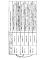
- Communication method 1 Communication without directivity control by base station instruction
- Communication method 2 Directivity communication by base station instruction
- Communication method 3 Non-continuous allocation without directivity control by base station instruction
- Communication method 4 are four patterns of directional communication by a base station instruction in spatial multiplexing and communication of non-continuous allocation.
- information size control in the base station 100 and the terminal 200 basically, communication without directivity control by the base station instruction and communication by non-sequential allocation without directivity control by the base station instruction are the same in one group.
- control section 101 assigns downlink allocations included in the PDCCH signal based on the number M of transmission antennas effective in its own device (M is a natural number) and the number N of transmission antennas effective in terminal 200 (N is a natural number). It is determined whether or not the information size of the control information and uplink allocation control information needs to be adjusted.
- control unit 101 determines that the information size adjustment is necessary in (communication method 1), and (communication method). In 2), it is determined that the adjustment of the information size is unnecessary.
- the information size adjusting unit 103 adjusts the information size of the downlink allocation control information and the uplink allocation control information included in the PDCCH signal based on the determination result regarding the necessity of the information size adjustment in the control unit 101.
- (Communication method 1) the above information size adjustment is required regardless of the number of antennas.
- (Communication method 2) when both M and N are plural, the information size adjustment is required, while one of M and N is plural and the other is one. In this case, the adjustment of the information size is not necessary.
- the information size adjustment unit 103 adjusts the information size of the downlink allocation control information and the uplink allocation control information included in the PDCCH signal based on the determination result regarding the necessity of the information size adjustment in the control unit 101.
- the information size adjusting unit 103 determines the information size of downlink allocation control information (that is, Format 1A) determined from the downlink frequency bandwidth and the corresponding uplink frequency bandwidth.
- the larger information size of the determined uplink allocation control information ie, Format 0
- the information size of the allocation control information is adjusted based on this size adjustment criterion.
- the larger one of the information size of the downlink allocation control information (ie, Format1B) and the uplink allocation control information (ie, Format0A) determined from the corresponding uplink frequency bandwidth and N is used as the size adjustment criterion. Based on the size adjustment criteria, the information size of the allocation control information is adjusted.
- the information size adjustment unit 103 determines downlink allocation control information (that is, Format1B) from the downlink frequency bandwidth and M.
- the information size of the downlink allocation control information to be applied is applied as it is.
- uplink allocation control information is not substantially transmitted. This is because when the number of transmitting antennas N of the terminal 200 is 1, it is impossible to perform (communication scheme 2) on the uplink only when holding a plurality of antennas on the transmitting side. This is because it is not necessary to transmit the uplink allocation control information (that is, Format0A) itself.
- the information size adjusting unit 103 determines the uplink allocation control information (that is, Format0A) from the uplink frequency bandwidth and N.
- the size of the uplink allocation control information to be applied is applied as it is.
- downlink allocation control information is not substantially transmitted. This is because, when the number M of transmission antennas of the base station 100 is 1, it is impossible to perform (communication method 2) on the downlink for the first time by holding a plurality of antennas on the transmission side. This is because it is not necessary to transmit downlink allocation control information (that is, Format1B) itself.
- the downlink channel signal is based on the communication scheme, the number M of transmission antennas of the base station 100, the number N of transmission antennas of the terminal 200, the bandwidth of the downlink, and the bandwidth of the uplink.
- the information sizes of the downlink allocation control information and the uplink allocation control information included in are adjusted.
- the information size-adjusted PDCCH signal is transmitted to terminal 200.
- information size determining section 209 determines a reference information size for blindly determining a received PDCCH signal.
- the reference information size includes the communication method applied between the base station 100 and the terminal 200, the number M of transmission antennas of the base station 100, the number N of transmission antennas of the terminal 200, the bandwidth of the downlink, and the bandwidth of the uplink Determined based on bandwidth. These pieces of information are shared between the base station 100 and the terminal 200 by communication in an upper layer.
- the information size determination unit 209 determines the information size of downlink allocation control information (that is, Format1A) determined from the downlink frequency bandwidth and the corresponding uplink frequency bandwidth.
- the reference information size is determined based on the larger one of the information sizes of the determined uplink allocation control information (that is, Format 0).
- the information size determining unit 209 determines the information size of the downlink allocation control information (that is, Format1B) determined from the downlink frequency bandwidth and M.
- the reference information size is determined based on the above.
- the information size determination unit 209 sets the size of the uplink allocation control information (that is, Format0A) determined from the uplink frequency bandwidth and N. Based on this, the reference information size is determined.
- the control unit 101 and the information size adjusting unit 103 are communication systems applied between the base station 100 and the terminal 200, and the transmission antenna of the base station 100.
- the information size of downlink allocation control information and uplink allocation control information included in the PDCCH signal is controlled based on the number M, the number N of transmission antennas of the terminal 200, the bandwidth of the downlink band, and the bandwidth of the uplink band.
- control unit 101 is established only when the selected communication method holds a plurality of antennas on the transmission side (for example, the above (communication method 2) and (communication method 4)).
- the selected communication method holds a plurality of antennas on the transmission side (for example, the above (communication method 2) and (communication method 4)).
- the control unit 101 determines that the information size needs to be adjusted regardless of the communication method.
- the information size adjusting unit 103 determines the information size of the downlink allocation control information determined from the downlink frequency bandwidth and M and the information size of the uplink allocation control information determined from the corresponding uplink frequency bandwidth and N. The larger one is used as the size adjustment reference, and the information size of the allocation control information is adjusted based on the size adjustment reference.
- the information size in each Format pair is determined in association with the number of transmission antennas of the base station 100 and the number of transmission antennas of the terminal 200.
- the base station 100 directly notifies the terminal 200 of information related to the information size determination method, that is, the number of effective transmission antennas on the base station side and the terminal side.
- the final reference information size may be determined based on this notification.
- terminal 200 calculates an initial value (indication of reference information size from base station 100, which is calculated based on the information size determination method described in the above embodiment). Default), and the final reference information size is determined according to an instruction from the base station 100.
- the number of effective transmission antennas is 1) or the lower mode (the number of effective transmission antennas of the base station is 1). It is assumed that both base station 100 and terminal 200 have a plurality of transmission antennas.
- the number of effective transmission antennas being one means that there is one antenna in a state where signals can be transmitted. As such a case, for example, there may be a case where only one transmission antenna is temporarily enabled because the remaining battery level is low.
- the base station decides whether or not to adjust the size of the allocation control information based on the number of antenna ports held by the base station and the terminal or the number of effective antenna ports.
- the base station 100 may directly notify the terminal of the information size determination method. That is, for each of (communication scheme 1), (communication scheme 2), (communication scheme 3), and (communication scheme 4), the base station performs the size of information performed between uplink allocation control information and downlink allocation control information. The presence / absence of adjustment may be notified for each terminal 200 individually.
- the terminal 200 sets the reference information size calculated based on the information size determination method described in the above embodiment as an initial value (default) until an instruction is received from the base station 100, and A final reference information size is determined according to an instruction from the station 100.
- FIGS. 5 and 6 the case where the “antenna port” and the physical antenna correspond one-to-one according to the embodiment is described as an example, but the “number of antennas” in FIGS. 5 and 6 is described. Even if is replaced with “antenna port”, the same effect can be obtained in the same embodiment.
- the base station 100 transmits a downlink signal using a single downlink frequency band
- the terminal 200 also transmits a single uplink frequency signal.
- the present invention is not limited to this. . That is, even when so-called Carrier aggregation is performed in which a plurality of bands defined by LTE are collectively communicated, this patent can be applied to each pair of upstream band and downstream band.
- the resource allocation type information transmitted with the size of the pair of Format1B and Format0A and the pair of Format2 and Format0C always indicates the uplink allocation signal. It will be. That is, a part corresponding to the type information of the resource allocation information may be used like a parity bit, another information may be transmitted, the bit itself indicating the type information is reduced, and the PDCCH effective information May improve the power per bit. The same applies when the number of transmitting antennas of the terminal is one.
- each functional block used in the description of the above embodiment is typically realized as an LSI which is an integrated circuit. These may be individually made into one chip, or may be made into one chip so as to include a part or all of them.
- the name used here is LSI, but it may also be called IC, system LSI, super LSI, or ultra LSI depending on the degree of integration.
- the method of circuit integration is not limited to LSI, and implementation with a dedicated circuit or a general-purpose processor is also possible.
- An FPGA Field Programmable Gate Array
- a reconfigurable processor that can reconfigure the connection and setting of circuit cells inside the LSI may be used.
- the radio terminal, radio base station, and channel signal forming method according to the present invention include a radio terminal having N (N is a natural number) transmission antenna ports and a radio base station having M (M is a natural number) transmission antenna ports.
- N is a natural number
- M is a natural number
- Downlink communication information or uplink allocation control information while preventing an increase in the number of times of blind determination at the radio terminal on the receiving side of the downlink control channel signal when communication using the downlink and uplink bands is performed By reducing the frequency with which the size adjustment processing is performed, it is useful as a means for preventing the quality deterioration of downlink allocation control information or uplink allocation control information.
Landscapes
- Engineering & Computer Science (AREA)
- Signal Processing (AREA)
- Computer Networks & Wireless Communication (AREA)
- Quality & Reliability (AREA)
- Physics & Mathematics (AREA)
- Mathematical Physics (AREA)
- Mobile Radio Communication Systems (AREA)
Abstract
Description
Claims (8)
- 送信アンテナポートをN(Nは自然数)個有する無線端末との間で下りバンド及び上りバンドを用いて通信し、送信アンテナポートをM(Mは自然数)個有する無線基地局であって、
下りバンドにおける下り割当制御情報及び上りバンドにおける上り割当制御情報を含む下りチャネル信号を形成する形成手段と、
自機と前記無線端末との間に適用される通信方式、自機の送信アンテナポート数M、前記無線端末の送信アンテナポート数N、前記下りバンドの帯域幅、及び、前記上りバンドの帯域幅に基づいて、前記形成された下りチャネル信号に含まれる前記下り割当制御情報及び前記上り割当制御情報の情報サイズを調整するサイズ制御手段と、
を具備する無線基地局。 - 前記サイズ制御手段は、前記通信方式、自機の送信アンテナポート数M及び前記無線端末の送信アンテナポート数Nに基づいて、前記情報サイズ調整の要否を決定する決定手段、を具備し、
前記決定手段は、前記通信方式が送信指向性制御を伴うものであり、前記送信アンテナポート数Nが1であり、且つ、前記送信アンテナポート数Mが2以上であるときに、前記情報サイズ調整が不要であると決定する、
請求項1に記載の無線基地局。 - 前記サイズ制御手段は、前記通信方式、自機の送信アンテナポート数M及び前記無線端末の送信アンテナポート数Nに基づいて、前記情報サイズ調整の要否を決定する決定手段、を具備し、
前記決定手段は、前記通信方式が送信指向性制御を伴うものであり、前記送信アンテナポート数Mが1であり、且つ、前記送信アンテナポート数Nが2以上であるときに、前記情報サイズ調整が不要であると決定する、
請求項1に記載の無線基地局。 - 前記サイズ制御手段は、ゼロ情報を付加することにより、下り割当制御情報及び上り割当制御情報の情報サイズを調整するパディング手段を含む、
請求項1に記載の無線基地局。 - 送信アンテナポートをM(Mは自然数)個有する無線基地局との間で下りバンド及び上りバンドを用いて通信し、送信アンテナポートをN(Nは自然数)個有する無線端末であって、
下りバンドにおける下り割当制御情報及び上りバンドにおける上り割当制御情報を含む下りチャネル信号を受信する無線受信手段と、
前記下りチャネル信号についての受信処理に用いる基準情報サイズを決定する決定手段と、
前記基準情報サイズに基づいてチャネル信号を受信処理するチャネル信号受信処理手段と、
を具備し、
前記決定手段は、自機と前記無線基地局との間に適用される通信方式、前記無線基地局の送信アンテナポート数M、自機の送信アンテナポート数N、前記下りバンドの帯域幅、及び、前記上りバンドの帯域幅に基づいて、前記基準情報サイズを決定する、
無線端末。 - 前記決定手段は、前記通信方式が送信指向性制御を伴うものであり、前記送信アンテナポート数Nが1であり、且つ、前記送信アンテナポート数Mが2以上であるときに、前記下りバンドの帯域幅から決まる情報サイズを前記基準情報サイズとする、
請求項5に記載の無線端末。 - 前記決定手段は、前記通信方式が送信指向性制御を伴うものであり、前記送信アンテナポート数Mが1であり、且つ、前記送信アンテナポート数Nが2以上であるときに、前記上りバンドの帯域幅から決まる情報サイズを前記基準情報サイズとする、
請求項5に記載の無線端末。 - 送信アンテナポートをN(Nは自然数)個有する無線端末と送信アンテナポートをM(Mは自然数)個有する無線基地局との間における下りバンド及び上りバンドを用いた通信を制御するために用いられる下りチャネル信号を形成するチャネル信号形成方法であって、
下りバンドにおける下り割当制御情報及び上りバンドにおける上り割当制御情報を含む下りチャネル信号を形成するステップと、
前記無線基地局と前記無線端末との間に適用される通信方式、前記無線基地局の送信アンテナポート数M、前記無線端末の送信アンテナポート数N、前記下りバンドの帯域幅、及び、前記上りバンドの帯域幅に基づいて、前記形成された下りチャネル信号に含まれる前記下り割当制御情報及び前記上り割当制御情報の情報サイズを調整するステップと、
を具備するチャネル信号形成方法。
Priority Applications (8)
| Application Number | Priority Date | Filing Date | Title |
|---|---|---|---|
| JP2010543912A JP5619625B2 (ja) | 2008-12-26 | 2009-12-25 | 通信装置、制御情報生成方法、及び集積回路 |
| US13/131,480 US8929307B2 (en) | 2008-12-26 | 2009-12-25 | Wireless base station, wireless terminal, and channel signal formation method |
| BRPI0923634A BRPI0923634A2 (pt) | 2008-12-26 | 2009-12-25 | estação de base sem fio, terminal sem fio e método de formação de sinal de canal |
| EP09834508A EP2373105A1 (en) | 2008-12-26 | 2009-12-25 | Wireless base station, wireless terminal, and channel signal formation method |
| US14/551,763 US9893849B2 (en) | 2008-12-26 | 2014-11-24 | Communication apparatus and control information receiving method |
| US15/836,240 US10715287B2 (en) | 2008-12-26 | 2017-12-08 | Communication apparatus and control information receiving method |
| US16/894,282 US11223454B2 (en) | 2008-12-26 | 2020-06-05 | Communication apparatus and method thereof |
| US17/539,703 US20220094489A1 (en) | 2008-12-26 | 2021-12-01 | Communication apparatus and method thereof |
Applications Claiming Priority (2)
| Application Number | Priority Date | Filing Date | Title |
|---|---|---|---|
| JP2008-332127 | 2008-12-26 | ||
| JP2008332127 | 2008-12-26 |
Related Child Applications (2)
| Application Number | Title | Priority Date | Filing Date |
|---|---|---|---|
| US13/131,480 A-371-Of-International US8929307B2 (en) | 2008-12-26 | 2009-12-25 | Wireless base station, wireless terminal, and channel signal formation method |
| US14/551,763 Continuation US9893849B2 (en) | 2008-12-26 | 2014-11-24 | Communication apparatus and control information receiving method |
Publications (1)
| Publication Number | Publication Date |
|---|---|
| WO2010073702A1 true WO2010073702A1 (ja) | 2010-07-01 |
Family
ID=42287335
Family Applications (1)
| Application Number | Title | Priority Date | Filing Date |
|---|---|---|---|
| PCT/JP2009/007254 WO2010073702A1 (ja) | 2008-12-26 | 2009-12-25 | 無線基地局、無線端末、及びチャネル信号形成方法 |
Country Status (5)
| Country | Link |
|---|---|
| US (5) | US8929307B2 (ja) |
| EP (1) | EP2373105A1 (ja) |
| JP (2) | JP5619625B2 (ja) |
| BR (1) | BRPI0923634A2 (ja) |
| WO (1) | WO2010073702A1 (ja) |
Cited By (5)
| Publication number | Priority date | Publication date | Assignee | Title |
|---|---|---|---|---|
| JP2012105185A (ja) * | 2010-11-12 | 2012-05-31 | Sharp Corp | 無線制御装置、無線端末装置、無線通信システム、無線制御装置および無線端末装置の制御プログラムおよび集積回路 |
| US8584270B2 (en) | 2008-11-21 | 2013-11-19 | Glyn David ROSSER | Toilet equipment |
| EP2704497A1 (en) * | 2011-04-27 | 2014-03-05 | Panasonic Corporation | Transmission device, receiving device, transmission method, and receiving method |
| US20140133422A1 (en) * | 2011-06-27 | 2014-05-15 | Panasonic Corporation | Transmitter device, receiver device, transmission method, and reception method |
| CN105556887A (zh) * | 2013-09-20 | 2016-05-04 | 高通股份有限公司 | 参考信号资源分配 |
Families Citing this family (7)
| Publication number | Priority date | Publication date | Assignee | Title |
|---|---|---|---|---|
| EP2355605B1 (en) * | 2008-12-01 | 2018-11-14 | Sun Patent Trust | Radio terminal, radio base station, channel signal forming method and channel signal receiving method |
| JP5619625B2 (ja) * | 2008-12-26 | 2014-11-05 | パナソニックインテレクチュアル プロパティ コーポレーション オブアメリカPanasonic Intellectual Property Corporation of America | 通信装置、制御情報生成方法、及び集積回路 |
| US9450659B2 (en) | 2011-11-04 | 2016-09-20 | Alcatel Lucent | Method and apparatus to generate virtual sector wide static beams using phase shift transmit diversity |
| CN103457709B (zh) * | 2012-05-31 | 2018-05-08 | 中兴通讯股份有限公司 | 一种控制信道的发送、接收方法及基站和终端 |
| JP2014027608A (ja) * | 2012-07-30 | 2014-02-06 | Ntt Docomo Inc | 基地局装置、ユーザ端末、通信システム及び通信制御方法 |
| BR112018003099A2 (pt) * | 2015-08-25 | 2018-09-25 | Nokia Solutions And Networks Oy | configuração de quadro de rádio |
| CN107484203A (zh) * | 2017-07-24 | 2017-12-15 | 武汉虹信通信技术有限责任公司 | 一种用于支持扩展带宽的数据传输方法 |
Family Cites Families (4)
| Publication number | Priority date | Publication date | Assignee | Title |
|---|---|---|---|---|
| US20080181180A1 (en) * | 2007-01-31 | 2008-07-31 | Jeyhan Karaoguz | Efficient network hand-off utilizing stored beam-forming information |
| KR101420879B1 (ko) * | 2007-11-29 | 2014-07-17 | 엘지전자 주식회사 | 스케줄링 정보에 관한 데이터의 전송방법 |
| EP2077646A1 (en) * | 2008-01-05 | 2009-07-08 | Panasonic Corporation | Control channel signaling using code points for indicating the scheduling mode |
| JP5619625B2 (ja) * | 2008-12-26 | 2014-11-05 | パナソニックインテレクチュアル プロパティ コーポレーション オブアメリカPanasonic Intellectual Property Corporation of America | 通信装置、制御情報生成方法、及び集積回路 |
-
2009
- 2009-12-25 JP JP2010543912A patent/JP5619625B2/ja active Active
- 2009-12-25 US US13/131,480 patent/US8929307B2/en active Active
- 2009-12-25 BR BRPI0923634A patent/BRPI0923634A2/pt not_active Application Discontinuation
- 2009-12-25 EP EP09834508A patent/EP2373105A1/en not_active Withdrawn
- 2009-12-25 WO PCT/JP2009/007254 patent/WO2010073702A1/ja active Application Filing
-
2014
- 2014-09-12 JP JP2014186203A patent/JP5767740B2/ja active Active
- 2014-11-24 US US14/551,763 patent/US9893849B2/en active Active
-
2017
- 2017-12-08 US US15/836,240 patent/US10715287B2/en active Active
-
2020
- 2020-06-05 US US16/894,282 patent/US11223454B2/en active Active
-
2021
- 2021-12-01 US US17/539,703 patent/US20220094489A1/en active Pending
Non-Patent Citations (5)
| Title |
|---|
| "Physical Channels and Modulation (Release 8", 3GPP TS 36.211 V8.4.0, September 2008 (2008-09-01) |
| "Physical layer procedures (Release 8", 3GPP TS 36.213 V8.4.0, September 2008 (2008-09-01) |
| "Uplink multiple access schemes for LTE-A", 3GPP TSG, September 2008 (2008-09-01) |
| MOTOROLA: "Indication of UE Antenna Selection for PUSCH", 3GPP TSG RAN WG1 #52 R1-080721, 11 February 2008 (2008-02-11), XP050109214 * |
| TEXAS INSTRUMENTS: "PDCCH Content and Formats", 3GPP TSG RAN WG1 52BIS RL-081367, 31 March 2008 (2008-03-31), XP050596691 * |
Cited By (9)
| Publication number | Priority date | Publication date | Assignee | Title |
|---|---|---|---|---|
| US8584270B2 (en) | 2008-11-21 | 2013-11-19 | Glyn David ROSSER | Toilet equipment |
| JP2012105185A (ja) * | 2010-11-12 | 2012-05-31 | Sharp Corp | 無線制御装置、無線端末装置、無線通信システム、無線制御装置および無線端末装置の制御プログラムおよび集積回路 |
| EP2704497A1 (en) * | 2011-04-27 | 2014-03-05 | Panasonic Corporation | Transmission device, receiving device, transmission method, and receiving method |
| EP2704497A4 (en) * | 2011-04-27 | 2014-10-08 | Panasonic Ip Corp America | TRANSMITTING DEVICE, RECEIVING DEVICE, TRANSMITTING METHOD, AND RECEIVING METHOD |
| US9320022B2 (en) | 2011-04-27 | 2016-04-19 | Panasonic Intellectual Property Corporation Of America | Transmission apparatus, receiveing apparatus, transmission method, and receiving method for mapping control signals to different resource regions within the same resource block |
| US20140133422A1 (en) * | 2011-06-27 | 2014-05-15 | Panasonic Corporation | Transmitter device, receiver device, transmission method, and reception method |
| US9398608B2 (en) * | 2011-06-27 | 2016-07-19 | Panasonic Intellectual Property Corporation Of America | Preventing erroneous detection of a data resource region due to an error in detection of a control signal |
| CN105556887A (zh) * | 2013-09-20 | 2016-05-04 | 高通股份有限公司 | 参考信号资源分配 |
| JP2016539518A (ja) * | 2013-09-20 | 2016-12-15 | クゥアルコム・インコーポレイテッドQualcomm Incorporated | 基準信号リソース割振り |
Also Published As
| Publication number | Publication date |
|---|---|
| US20110222503A1 (en) | 2011-09-15 |
| JP5619625B2 (ja) | 2014-11-05 |
| US20180102884A1 (en) | 2018-04-12 |
| US20150078316A1 (en) | 2015-03-19 |
| EP2373105A1 (en) | 2011-10-05 |
| US8929307B2 (en) | 2015-01-06 |
| BRPI0923634A2 (pt) | 2016-01-19 |
| US9893849B2 (en) | 2018-02-13 |
| JPWO2010073702A1 (ja) | 2012-06-14 |
| US10715287B2 (en) | 2020-07-14 |
| JP5767740B2 (ja) | 2015-08-19 |
| US20220094489A1 (en) | 2022-03-24 |
| US20200304254A1 (en) | 2020-09-24 |
| US11223454B2 (en) | 2022-01-11 |
| JP2014233089A (ja) | 2014-12-11 |
Similar Documents
| Publication | Publication Date | Title |
|---|---|---|
| US11223454B2 (en) | Communication apparatus and method thereof | |
| US11689986B2 (en) | Terminal and communication method thereof | |
| US8891469B2 (en) | Radio transmitting apparatus and control signal transmitting method | |
| JP5748885B2 (ja) | 端末装置、通信方法および集積回路 | |
| JP5756878B2 (ja) | 通信装置、送信方法及び集積回路 | |
| US20110134872A1 (en) | Base station and terminal | |
| JP5361902B2 (ja) | 無線通信装置および無線通信方法 | |
| KR20180061164A (ko) | 장치, 방법 및 프로그램 | |
| WO2010146867A1 (ja) | 無線送信装置及び送信電力制御方法 |
Legal Events
| Date | Code | Title | Description |
|---|---|---|---|
| 121 | Ep: the epo has been informed by wipo that ep was designated in this application |
Ref document number: 09834508 Country of ref document: EP Kind code of ref document: A1 |
|
| WWE | Wipo information: entry into national phase |
Ref document number: 2010543912 Country of ref document: JP |
|
| WWE | Wipo information: entry into national phase |
Ref document number: 13131480 Country of ref document: US |
|
| WWE | Wipo information: entry into national phase |
Ref document number: 2009834508 Country of ref document: EP |
|
| NENP | Non-entry into the national phase |
Ref country code: DE |
|
| REG | Reference to national code |
Ref country code: BR Ref legal event code: B01A Ref document number: PI0923634 Country of ref document: BR |
|
| ENP | Entry into the national phase |
Ref document number: PI0923634 Country of ref document: BR Kind code of ref document: A2 Effective date: 20110624 |