WO2010070852A1 - 無線通信システム、無線通信方法及び送信方法 - Google Patents
無線通信システム、無線通信方法及び送信方法 Download PDFInfo
- Publication number
- WO2010070852A1 WO2010070852A1 PCT/JP2009/006795 JP2009006795W WO2010070852A1 WO 2010070852 A1 WO2010070852 A1 WO 2010070852A1 JP 2009006795 W JP2009006795 W JP 2009006795W WO 2010070852 A1 WO2010070852 A1 WO 2010070852A1
- Authority
- WO
- WIPO (PCT)
- Prior art keywords
- transmission
- signal
- unit
- propagation path
- cluster
- Prior art date
- Legal status (The legal status is an assumption and is not a legal conclusion. Google has not performed a legal analysis and makes no representation as to the accuracy of the status listed.)
- Ceased
Links
Images







Classifications
-
- H—ELECTRICITY
- H04—ELECTRIC COMMUNICATION TECHNIQUE
- H04L—TRANSMISSION OF DIGITAL INFORMATION, e.g. TELEGRAPHIC COMMUNICATION
- H04L5/00—Arrangements affording multiple use of the transmission path
- H04L5/003—Arrangements for allocating sub-channels of the transmission path
- H04L5/0037—Inter-user or inter-terminal allocation
-
- H—ELECTRICITY
- H04—ELECTRIC COMMUNICATION TECHNIQUE
- H04L—TRANSMISSION OF DIGITAL INFORMATION, e.g. TELEGRAPHIC COMMUNICATION
- H04L1/00—Arrangements for detecting or preventing errors in the information received
- H04L1/004—Arrangements for detecting or preventing errors in the information received by using forward error control
- H04L1/0045—Arrangements at the receiver end
- H04L1/0047—Decoding adapted to other signal detection operation
- H04L1/005—Iterative decoding, including iteration between signal detection and decoding operation
-
- H—ELECTRICITY
- H04—ELECTRIC COMMUNICATION TECHNIQUE
- H04L—TRANSMISSION OF DIGITAL INFORMATION, e.g. TELEGRAPHIC COMMUNICATION
- H04L5/00—Arrangements affording multiple use of the transmission path
- H04L5/003—Arrangements for allocating sub-channels of the transmission path
- H04L5/0058—Allocation criteria
-
- H—ELECTRICITY
- H04—ELECTRIC COMMUNICATION TECHNIQUE
- H04L—TRANSMISSION OF DIGITAL INFORMATION, e.g. TELEGRAPHIC COMMUNICATION
- H04L25/00—Baseband systems
- H04L25/02—Details ; arrangements for supplying electrical power along data transmission lines
- H04L25/03—Shaping networks in transmitter or receiver, e.g. adaptive shaping networks
- H04L25/03006—Arrangements for removing intersymbol interference
- H04L25/03178—Arrangements involving sequence estimation techniques
- H04L25/03248—Arrangements for operating in conjunction with other apparatus
- H04L25/03286—Arrangements for operating in conjunction with other apparatus with channel-decoding circuitry
-
- H—ELECTRICITY
- H04—ELECTRIC COMMUNICATION TECHNIQUE
- H04W—WIRELESS COMMUNICATION NETWORKS
- H04W72/00—Local resource management
- H04W72/20—Control channels or signalling for resource management
Definitions
- the present invention relates to a radio communication system, a radio communication method, and a transmission method in which a plurality of transmission apparatuses perform radio transmission to the same reception apparatus.
- This application claims priority based on Japanese Patent Application No. 2008-319732 for which it applied to Japan on December 16, 2008, and uses the content here.
- DSC dynamic spectrum control
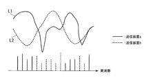
- FIGS. 8A to 8C are conceptual diagrams showing examples of signal arrangement by DSC.
- FIGS. 8A to 8C illustrate an example in which two transmission apparatuses (transmission apparatus a and transmission apparatus b) transmit signals to one reception apparatus.
- FIG. 8A represents an example of a frequency signal transmitted by the transmission apparatus a by a solid line
- FIG. 8B represents an example of a frequency signal transmitted by the transmission apparatus b by a dotted line.
- FIG. 8C shows an example of assignment of discrete spectrum units when the transmission apparatus a and the transmission apparatus b transmit signals to the same reception apparatus by DSC.
- the horizontal axis represents frequency
- the vertical axis represents the intensity of these signal spectra.
- L1 represents a frequency response (propagation path characteristic) of a frequency signal propagation path from the transmission apparatus a to the reception apparatus
- L2 represents a frequency response of a frequency signal propagation path from the transmission apparatus b to the reception apparatus.
- L1 and L2 indicate that the higher the value in the vertical axis direction, the better the channel characteristics at that frequency.
- each transmitting device (transmitting device a and transmitting device b) generates a modulation symbol corresponding to the number of discrete spectrums allocated to the own device, and converts this into a frequency signal by discrete Fourier transform (DFT). Convert.
- each transmission apparatus arranges frequency signals in discrete spectrum units according to the magnitude of the frequency response of the propagation path from the respective transmission apparatus to the reception apparatus.
- a frequency signal is preferentially arranged with respect to a discrete spectrum having a high frequency response of a propagation path in each transmission apparatus, and a plurality of transmission apparatuses (in this case, transmission apparatus a and The frequency signals are arranged in discrete spectral units so that the transmitting device b) does not allocate frequency signals.
- a high frequency selection diversity effect is obtained.
- the signal arrangement in other transmission devices also becomes a limitation on the allocation of discrete spectra.
- the transmission device a cannot arrange the frequency signal in the discrete spectrum and realizes the optimum arrangement. There are things that cannot be done.
- the frequency selection diversity effect may be reduced depending on the signal arrangement in other transmission apparatuses.
- Non-Patent Document 1 on the premise that turbo equalization technology is applied to signal detection processing by a receiving device, by allowing the discrete spectrum of each transmitting device to overlap with the discrete spectrum of another transmitting device,
- SORM spectrum-overlapped resource management
- FIG. 9A to 9C are conceptual diagrams showing examples of signal arrangement by SORM.
- FIG. 9A shows an example of a frequency signal in the transmission apparatus a.
- FIG. 9B shows an example of a frequency signal in the transmission apparatus b.
- FIG. 9C shows an example of assignment of discrete spectrum units when the transmission device a and the transmission device b transmit signals to the same reception device by SORM.
- L1 represents the frequency response of the propagation path in the transmission apparatus a
- L2 represents the frequency response of the propagation path in the transmission apparatus b.
- the turbo equalization technique is applied to the signal detection processing by the receiving device, so that the transmission signal of the transmission device a and the transmission signal of the transmission device b are separated even in the overlapping discrete spectrum. It is possible. For this reason, it is possible to assign a discrete spectrum according to only the transmission path condition, regardless of whether or not signal assignments overlap with other transmission apparatuses in the same discrete spectrum. Therefore, the maximum frequency selection diversity is obtained in the transmittable system band, and the throughput is improved.
- an object of the present invention is to provide a radio communication system and a radio communication method that can reduce the amount of information of allocation information related to frequency signals transmitted and received between each of a plurality of transmission apparatuses and a reception apparatus.
- One embodiment of the present invention is a wireless communication system including a plurality of transmission devices that wirelessly transmit signals and a reception device that wirelessly receives signals from the plurality of transmission devices, wherein the transmission device includes: A coding unit that performs error correction coding on the data to be transmitted and generates code bits; a modulation unit that performs modulation processing on the code bits and generates a plurality of modulation symbols; and the plurality of modulation symbols as frequency signals.
- a DFT unit that converts the frequency signal into a plurality of frequency signals, a cluster dividing unit that divides the plurality of frequency signals into clusters including a plurality of frequency signals, and generates a smaller number of clusters than the total number of the plurality of frequency signals, and resource block allocation information And a cluster placement unit for placing the clusters in resource blocks including a plurality of discrete spectra, and each cluster is placed in each resource block.
- An IDFT unit that converts a frequency signal into a time signal, a reference signal multiplexing unit that multiplexes a reference signal for estimating propagation path characteristics with respect to the time signal, and a signal in which the reference signal is multiplexed is increased to a radio frequency.
- a radio transmission unit that performs radio transmission after conversion, and the reception device includes a radio reception unit that receives a signal from each transmission device and generates a reception signal by down-conversion from a radio frequency, and is included in the reception signal
- a propagation path estimator that estimates propagation path characteristics in each transmission apparatus based on a reference signal of each transmission apparatus, an equalization section that compensates for distortion due to the propagation path, and a decoding section that performs error correction processing on the received signal
- the same resource block is allocated to a plurality of transmission apparatuses in the turbo equalization processing unit that detects the data before encoding by repeating the process of Regardless of whether or not, based on the estimation result of the propagation path characteristic by the propagation path estimation unit, each transmission apparatus allocates the resource block that can be used for signal transmission to each transmission apparatus, and represents the resource block
- a scheduling unit that generates allocation information and transmits the allocation information to each transmission device.
- the reception device includes the same number of turbo equalization processing units as the number of the plurality of transmission devices, and each turbo equalization processing unit is received from a different transmission device.
- the reception signal may be processed.
- the reception apparatus includes a smaller number of antennas than the number of the plurality of transmission apparatuses, and the scheduling unit transmits the same resource block more than the number of antennas. Regardless of whether or not it is assigned to a device, based on the estimation result of propagation path characteristics by the propagation path estimation unit, each transmission device allocates the resource block that can be used for signal transmission to each transmission device, and It may be configured to generate resource block allocation information representing allocation contents and transmit the generated resource block allocation information to each transmitting apparatus.
- One aspect of the present invention is a wireless communication method performed by a wireless communication system including a plurality of transmission devices that wirelessly transmit signals and a reception device that wirelessly receives signals from the plurality of transmission devices.
- the transmission apparatus performs error correction coding on data to be transmitted and generates code bits; performs modulation processing on the code bits to generate a plurality of modulation symbols; and A DFT step for converting to a modulation symbol frequency signal, a cluster division step for dividing the plurality of frequency signals into clusters including a plurality of frequency signals, and generating a number of clusters smaller than the total number of the plurality of frequency signals;
- An IDFT step for converting a frequency signal in which each cluster is arranged in each resource block into a time signal; a reference signal multiplexing step for multiplexing a reference signal for estimating a propagation path characteristic with respect to the time signal; and the
- each transmission device transmits a signal based on the estimation result of the propagation channel characteristics by the propagation channel estimation unit. And a scheduling step of allocating the resource blocks that can be used to each transmitting apparatus, generating resource block allocation information representing the allocation contents, and transmitting the resource block allocation information to each transmitting apparatus.
- One aspect of the present invention is a transmission method for wirelessly transmitting a signal from a plurality of transmission devices to a single reception device, and each transmission device is more than the total number of a plurality of frequency signals to be transmitted.
- a small number of clusters are generated, and the clusters are arranged in a resource block including a plurality of discrete spectra. In this case, the arrangement is performed based only on propagation path characteristics in each transmitting apparatus.
- the allocation information related to the frequency signal transmitted / received between each of the plurality of transmission devices and the reception device is expressed in cluster units (resource block units) including a plurality of discrete spectra. Therefore, it is possible to reduce the information amount of the allocation information compared to the case where the allocation information is expressed in discrete spectrum units.
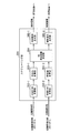
- FIG. 3 is a schematic block diagram illustrating a functional configuration of a scheduling unit in FIG. 2. 4 is a flowchart showing the processing of the scheduling unit. It is a figure showing the concept of the system at the time of applying the multiuser MIMO of 2nd embodiment of this invention.
- a cluster includes a predetermined number (two or more) of frequency signals and is created in each transmission device.
- the cluster size represents the number of frequency signals included in each cluster.
- Information regarding the cluster size is shared by being determined in advance or transmitted and received as control information in the transmission device and the reception device.
- a resource block (hereinafter referred to as “RB”) represents a group of discrete spectra that can be allocated at the time of transmission, and an RB size represents the number of discrete spectra included in each RB.
- the cluster size and the RB size coincide with each other and are 12 (that is, each cluster and each RB includes 12 discrete spectra), but are not limited thereto.
- the transmission method may be a single carrier transmission method or a multicarrier transmission method.
- FIG. 1A to 1C are conceptual diagrams showing the concept of clusters.
- FIG. 1A shows an example of a cluster in the transmission device a.
- FIG. 1B shows an example of a cluster in the transmission apparatus b.
- 1A to 1C a cluster to which a frequency signal is assigned in the transmission device a is represented by a white rectangle, and a cluster to which the frequency signal is assigned in the transmission device b is represented by a hatched rectangle.
- FIG. 1C shows an example of cluster assignment for each RB when the transmission device a and the transmission device b transmit signals to the same reception device by SORM. 1A, 1B, and 1C, the horizontal axis indicates the frequency.
- FIG. 1A, 1B, and 1C the horizontal axis indicates the frequency.
- L1 represents the frequency response of the propagation path in the transmission apparatus a
- L2 represents the frequency response of the propagation path in the transmission apparatus b
- L1 and L2 represent values such as a signal-to-interference noise power ratio (signal to interference plus noise power ratio (SINR)), and the higher the value in the vertical axis direction, the higher the value. It shows that the characteristics of the propagation path at the frequency are good.
- SINR signal-to-interference noise power ratio
- the transmitting apparatus a clusters a plurality of frequency signals obtained by DFT into clusters C1-1 to C4-1.
- Each of the clusters C1-1 to C4-1 includes 12 frequency signals.
- the transmission apparatus b clusters a plurality of frequency signals obtained by DFT into clusters C1-2 to C4-2.
- each transmitting apparatus divides the entire system band (the entire band that can be used by the transmitting apparatus a and the transmitting apparatus b) by the RB size, and the cluster of each transmitting apparatus has a good propagation path condition for each transmitting apparatus. Place in RB.
- clusters are overlapped by the transmission device a and the transmission device b.
- turbo equalization processing is applied in the receiving apparatus, even if a plurality of transmitting apparatuses arrange and transmit signals overlapping the same cluster in this way, each transmitting apparatus It becomes possible to detect the signal transmitted from the receiver.
- FIG. 2 is a schematic block diagram showing the functional configuration of the transmission apparatus.
- the transmission apparatus includes an encoding unit 101, an interleaving unit 102, a modulating unit 103, a DFT unit 104, a cluster dividing unit 105, a cluster allocation detecting unit 106, a cluster arranging unit 107, an IDFT (Inverse DFT) unit 108, a reference signal generating unit 109, A reference signal multiplexing unit 110, a CP (Cyclic Prefix) insertion unit 111, a radio unit 112, a transmission antenna 113, a reception unit 114, and a reception antenna 115 are provided.
- CP Common DFT
- the encoding unit 101 performs error correction encoding on an information bit string that is data to be transmitted, and generates a code bit.
- Interleaving section 102 rearranges the code bits in time order.
- Modulation section 103 performs modulation by mapping the information of code bits in which the time order is rearranged to amplitude and phase, and generates a plurality of modulation symbols.
- the DFT unit 104 performs a discrete Fourier transform on the plurality of modulation symbols to generate a frequency signal.
- the transmission device includes a DFT unit 104 that receives input of modulation symbols by the number of symbols to be transmitted in one transmission.
- the cluster dividing unit 105 clusters frequency signals according to the cluster size. In other words, the cluster dividing unit 105 generates a cluster shown in FIG. 1A and FIG. 1B by setting the frequency signals equal to the cluster size as one cluster.
- the cluster allocation detection unit 106 detects cluster allocation information from the control information notified from the receiving device.
- the cluster allocation information is information determined by the receiving device, and is information indicating resource blocks that can be used by each transmitting device during transmission. That is, each transmission device detects the frequency of a resource block that can be used by itself by referring to the cluster allocation information.
- the cluster placement unit 107 places each cluster generated by the cluster partitioning unit 105 in the RB based on the cluster allocation information as shown in FIG. 1C.
- the control information is a base station corresponding to the receiving apparatus in this embodiment. It is included in a signal called PDCCH (Physical Downlink Control Channel) transmitted from the apparatus to the mobile station apparatus corresponding to the transmitting apparatus.
- PDCCH Physical Downlink Control Channel
- the IDFT unit 108 converts the frequency signal of the cluster arranged in the RB into a time signal by IDFT.
- the reference signal generation unit 109 generates a reference signal for estimating propagation path characteristics.
- the reference signal multiplexing unit 110 multiplexes the reference signal with the time signal obtained by the IDFT unit 108.
- CP insertion section 111 inserts a CP into the signal multiplexed with the reference signal.
- CP Cyclic Prefix
- the radio unit 112 up-converts the signal with the CP inserted into a radio frequency and transmits it from the transmission antenna 113.
- the reception unit 114 receives a control information signal including allocation information from the reception device via the reception antenna 115, performs down-conversion, demodulation processing, decoding processing, and the like on the signal to generate control information,
- the data is output to the cluster allocation detection unit 106.
- the receiving antenna 115 receives a control information signal including allocation information from the receiving apparatus.
- FIG. 3 is a schematic block diagram showing the functional configuration of the receiving apparatus.
- the receiving device shown in FIG. 3 has a configuration for simultaneously receiving signals from two transmitting devices (transmitting device a and transmitting device b).
- the reception apparatus includes a reception antenna 201, a radio unit 202, a CP removal unit 203, a reference signal separation unit 204, a propagation path estimation unit 205-1 and 205-2, a first DFT unit 206, a soft cancellation unit 207, and a cluster extraction unit 208.
- the units 217-1 and 217-2, the cluster division units 218-1 and 218-2, the cluster placement units 219-1 and 219-2, and the propagation path product units 220-1 and 220-2 correspond to the receiving devices, respectively. As many transmission devices as possible are provided in the reception device.
- each of the functional units is provided in two.
- those with “-1” added to the reference numerals of the functional units operate corresponding to the transmission apparatus a, and those with “ ⁇ 2” attached to the transmission apparatus b. Operate.
- the receiving antenna 201 receives a signal transmitted from each transmitting device.
- Radio section 202 down-converts the received signal from a radio frequency to a baseband frequency and outputs it.
- CP removing section 203 removes the CP from the received signal obtained from radio section 202.
- the reference signal separation unit 204 separates the reference signal of each transmission device from the reception signal from which the CP has been removed.
- the propagation path estimators 205-1 and 205-2 estimate propagation path characteristics representing the frequency response of the propagation path from each transmission apparatus based on the reference signal of each transmission apparatus from which the reference signal is separated.
- the propagation path estimators 205-1 and 205-2 notify the scheduling section 221 of the propagation path characteristics estimated by each.
- the first DFT unit 206 converts the received signal from which the reference signal is separated into a frequency signal. Then, turbo equalization processing is performed on the frequency signal by the functional units from the soft cancel unit 207 to the propagation path product units 220-1 and 220-2.
- the soft cancellation unit 207 cancels the soft replica input from the propagation path product units 220-1 and 220-2 from the frequency signal, and outputs the result. However, since the soft replica is not created in the first iteration of the turbo equalization process, the frequency signal input from the first DFT unit 206-1 is output as it is.
- the cluster extraction unit 208 inserts zeros into a signal in a frequency band other than the frequency band used by each transmission device for the output signal from the soft cancellation unit 207, and an equalization unit 209-1 corresponding to each transmission device, Output to 209-2. That is, the cluster extraction unit 208 outputs to the equalization unit 209-1 a signal in which only the frequency signal in the frequency band used by the transmission device a is left and the remaining zeros are inserted. Further, the cluster extraction unit 208 outputs to the equalization unit 209-2 a signal in which only the frequency signal in the frequency band used by the transmission apparatus b is left and the remaining zeros are inserted.
- the equalization units 209-1 and 209-2 perform equalization processing for compensating for the distortion of the propagation path based on the propagation path characteristics estimated by the propagation path estimation units 205-1 and 205-2 for the respective signals.
- Cluster combining sections 210-1 and 210-2 perform a process opposite to the arrangement of clusters for RBs, that is, a combination process for combining clusters arranged in each RB in order with respect to the frequency signals after equalization processing. To obtain the same number of frequency signals as the transmission signals generated by the DFT unit 104 of the transmission apparatus. In the first iteration of the turbo equalization process, there is no input from the second DFT units 217-1 and 217-2 to the cluster combining units 210-1 and 210-2.
- IDFT units 211-1 and 211-2 perform inverse discrete Fourier transform on the frequency signal to convert it into a time signal.
- the demodulating units 212-1 and 212-2 demodulate the time signal and decompose it into code bits.
- the deinterleaving units 213-1 and 213-2 rearrange the order of time rearranged by the interleaving unit 102 and restore it.
- the decoding units 214-1 and 214-2 decode the error correction code into the code bits output from the deinterleave units 213-1 and 213-2 after the turbo equalization processing is completed, The decoded bit is output to the illustrated data processing unit.
- the decoding units 214-1 and 214-2 perform error correction processing using error correction codes on the interleaving units 215-1 and 215-2, and calculate the calculated code bits.
- a log likelihood ratio (LLR) is output.
- Interleave sections 215-1 and 215-2 perform rearrangement in the time order on the LLRs of the respective code bits in the same manner as the rearrangement in time order performed by interleave section 102 of the transmission apparatus.
- Soft replica generation units 216-1 and 216-2 generate soft replicas of modulation symbols proportional to the reliability obtained from the LLRs in which the time order is rearranged.
- the modulation scheme by the modulation unit 103 of the transmission apparatus is quadrature phase modulation (QPSK: Quadrature Phase Shift Keying), and the LLRs of the first and second bits of the code bits constituting the QPSK symbol are ⁇ 1 and ⁇ 2, respectively.
- QPSK Quadrature Phase Shift Keying
- the second DFT units 217-1 and 217-2 perform DFT on the soft replica to generate a frequency signal soft replica.
- Cluster division units 218-1 and 218-2 and cluster arrangement units 219-1 and 219-2 perform processing similar to that performed by cluster division unit 105 and cluster arrangement unit 107 of each transmission device.
- the propagation path product units 220-1 and 220-2 multiply the propagation path characteristics estimated by the propagation path estimation units 205-1 and 205-2 on the frequency signal soft replicas in which the clusters are arranged. Thus, a received signal replica is generated.
- the soft cancellation unit 207 cancels the frequency signal replicas of all transmission apparatuses from the reception signal.
- the function units from the cluster extraction unit 208, equalization units 209-1 and 209-2, IDFT units 211-1 and 211-2 to propagation path product units 220-1 and 220-2 are used for the first iteration process. Perform the same process as The cluster combining units 210-1 and 210-2 execute the combining process, and reconfigure the soft replica obtained by the second DFT units 217-1 and 217-2.
- the reason why this processing is performed is that the soft cancellation unit 207 cancels all received signals including not only the interference signal but also the desired signal (transmission signal).
- equalization processing generally involves an inverse matrix operation, canceling all soft replicas once can be handled in common when detecting signals from all transmitters, and interference signals This is because the inverse matrix calculation needs to be performed only once when the cancellation and equalization processing are performed.
- the receiving apparatus repeats the above iterative process in the turbo equalization process an arbitrary number of times (for example, a predetermined number of times or until there is no error), and finally, from the decoding units 214-1 and 214-2, respectively, The decoded bit of the transmission signal by the apparatus b is output.
- the reception apparatus performs the turbo equalization process, even when a cluster of a plurality of transmission apparatuses is arranged in a part of some RBs, it is possible to separate the transmission signals. Therefore, since a plurality of transmission devices can arrange clusters in the same RB, each transmission device is optimally suited to its own propagation path characteristics regardless of the cluster arrangement of other transmission devices. Cluster arrangement can be realized, and a high frequency selection diversity effect can be obtained.
- FIG. 4 is a schematic block diagram showing a functional configuration of the scheduling unit 221 of the receiving device.
- Scheduling section 221 includes reception SINR calculation sections 302-1 and 302-2, RB quality calculation sections 303-1 and 303-2, RB allocation information determination section 304, and control information generation sections 305-1 and 305-2.
- the propagation path characteristics of the respective transmission devices estimated by the propagation path estimation sections 205-1 and 205-2 are input to the reception SINR calculation sections 302-1 and 302-2, respectively.
- Reception SINR calculation sections 302-1 and 302-2 calculate the reception signal-to-interference noise power ratio (SINR) of each discrete spectrum based on the input propagation path characteristics.
- SINR reception signal-to-interference noise power ratio
- RB quality calculation sections 303-1 and 303-2 calculate the reception SINR of each RB in the entire transmittable band based on the reception SINR calculated by reception SINR calculation sections 302-1 and 302-2.
- the reception SINR value of each RB calculated by the RB quality calculation units 303-1 and 303-2 may be an average value in the RB, a minimum value, or a sum. May be.
- the value calculated by RB quality calculation sections 303-1 and 303-2 is an average value of received SINR of each discrete spectrum included in each RB.
- the RB allocation information determination unit 304 determines the RB allocation information so as to allocate an RB having a high reception SINR to each transmission apparatus, regardless of whether or not they overlap, based on the reception SINR value of each RB.
- the RB allocation information is information representing an RB that can be used by each transmitting apparatus during signal transmission.
- the RB allocation information is represented using a frequency value of each RB, identification information allocated in advance to each RB, or the like.
- Control signal generation sections 305-1 and 305-2 generate control signals including RB allocation information of each transmission apparatus, and convert them into a signal format (for example, PDCCH) notified to each transmission apparatus. Each signal after conversion is output to transmission section 222 (FIG. 3). The transmission unit 222 up-converts the control signal and transmits it to the reception device via the transmission antenna 223.
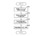
- FIG. 5 is a flowchart showing the processing of the scheduling unit 221.
- each received SINR calculation unit 302-1 and 302-2 calculates the received SINR of each discrete spectrum based on the propagation path characteristics (step S101).
- the RB quality calculation units 303-1 and 303-2 calculate the reception SINR in units of RBs based on the reception SINR of each discrete spectrum (step S102).
- the RB allocation information determination unit 304 allocates RBs that can be used by each transmission apparatus at the time of transmission to each transmission apparatus based on the reception SINR in units of RBs (step S103), and RB allocation information indicating the contents of this allocation Create Then, a radio unit (not shown) transmits a signal including RB allocation information to each transmission device (step S104).
- the allocation information transmitted and received between each transmitting apparatus and receiving apparatus is expressed not in discrete spectral units but in cluster units.
- control information can be reduced. For example, when the cluster size matches the RB size and the RB size is 12 as in the present embodiment, the amount of control information can be reduced to about 1/12.
- the transmitting device described above is applied not only to a fixed communication network but also to, for example, a mobile station device (more specifically, a mobile phone) in a mobile communication network system, and the receiving device described above is applied to, for example, a base station device. It is possible to apply.
- the cluster size and the RB size do not need to be 12, and may be less than 12 or larger than 12.
- reception SINR calculation sections 302-1 and 302-2 need not be limited to the reception SINR of each discrete spectrum, and may be other values as long as the quality of each discrete spectrum can be evaluated. May be.
- the above-described embodiments need not be limited to SORM.
- OFDM Orthogonal Frequency Division Multiplexing
- MC-CDM Multi-Carrier Code Division Multiplexing
- uplink communication (communication from the mobile station apparatus to the base station apparatus) is targeted, but the same technique is applied to downlink communication (communication from the base station apparatus to the mobile station apparatus). ) May be applied. In that case, the transmitting apparatus becomes a base station apparatus, and the receiving apparatus becomes a mobile station apparatus.
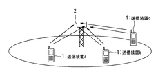
- FIG. 6 is a conceptual diagram showing a concept when multi-user MIMO (Multiple-Input Multiple-Output) is applied.
- MIMO Multiple-Input Multiple-Output
- the receiving device 2 includes a plurality of receiving antennas and signals of a plurality of transmitting devices 1 (transmitting device a to transmitting device c) are spatially multiplexed
- the receiving device includes two receiving antennas.
- Ordinary multi-user MIMO cannot spatially multiplex more than a number of receiving antennas. Therefore, in the case of FIG. 6, for example, only the signals of the transmission device a and the transmission device b can be multiplexed.
- the configuration of the receiving device 2 in this case is basically the same as the configuration shown in FIG. 3, and functional units (propagation path estimating units 205-1 and 205-2 that increase or decrease depending on the number of compatible transmitting devices.
- Equalization units 209-1, 209-2, cluster combining units 210-1, 210-2, IDFT units 211-1, 211-2, demodulation units 212-1, 212-2, deinterleaving unit 213-1, 213-2, decoding units 214-1, 214-2, interleaving units 215-1, 215-2, soft replica generation units 216-1, 216-2, second DFT units 217-1, 217-2, cluster division Sections 218-1 and 218-2, cluster placement sections 219-1 and 219-2, propagation path product sections 220-1 and 220-2) are respectively provided to correspond to the three transmission apparatuses a to c.
- equalization units 209-1 to 209-3 have two receiving antennas, a desired signal (for example, signal of transmission apparatus a if equalization unit 109-1) is synthesized with the same phase. Equalization processing (receive diversity method such as maximum ratio combining) is performed.
- FIG. 7 is a schematic diagram illustrating an example of RB allocation to each transmission device 1.
- three clusters of the transmission device a, the transmission device b, and the transmission device c are multiplexed on the RB3. That is, the cluster to which the frequency signal is assigned in the transmission apparatus a is arranged in the resource blocks RB1, RB3, RB4, and RB6, and the cluster to which the frequency signal is assigned in the transmission apparatus b is arranged in the resource blocks RB1, RB2, RB3, and RB5. Then, the cluster to which the frequency signal is allocated in the transmission apparatus c is arranged in the resource blocks RB2, RB3, RB5, and RB6.
- RB3 is overlapped by the transmission device a, the transmission device b, and the transmission device c.
- the signal of the transmission device c is arranged in the free spectrum of the transmission device a and the transmission device b.
- the transmission device c places a signal in an empty band that is not used by the transmission device a and the transmission device b, and thus the transmission device c has good reception quality. There is a problem that a signal cannot be selected because the correct frequency cannot be selected.
- the transmission device c can independently perform the arrangement according to the propagation path characteristics without considering the cluster arrangement on the RB in the transmission device a and the transmission device b. As a result, the signals of all the transmission devices including the transmission device c can acquire frequency selection diversity, and good transmission characteristics can be obtained.
- the function of the scheduling unit 221 in the above-described embodiment may be realized by a computer. In that case, it may be realized by recording a program for realizing the function of the scheduling unit 221 on a computer-readable recording medium, causing the computer system to read the program recorded on the recording medium, and executing the program. good.
- the “computer system” includes an OS and hardware such as peripheral devices.
- the “computer-readable recording medium” refers to a storage device such as a flexible medium, a magneto-optical disk, a portable medium such as a ROM or a CD-ROM, and a hard disk incorporated in a computer system.
- the “computer-readable recording medium” dynamically holds a program for a short time like a communication line when transmitting a program via a network such as the Internet or a communication line such as a telephone line.
- a volatile memory inside a computer system serving as a server or a client in that case may be included and a program that holds a program for a certain period of time.
- the program may be a program for realizing a part of the functions described above, and may be a program capable of realizing the functions described above in combination with a program already recorded in a computer system.
- the present invention is suitable for application to both fixed wireless communication and mobile communication.
- Equalization part 210 ... Cluster combination part, 211 ... IDFT part, 212 ... Demodulation part, 213 ... Deinterleave part, 214 ... decoding part, 215 ... interleaving part, 216 ... software Preca generator, 217 ... second DFT, 218 ... cluster partition, 219 ... cluster placement, 220 ... propagation product, 221 ... schedule, 302 ... receive SINR calculator, 303 ... RB quality calculator, 304: RB allocation information determination unit, 305: Control signal generation unit
Landscapes
- Engineering & Computer Science (AREA)
- Signal Processing (AREA)
- Computer Networks & Wireless Communication (AREA)
- Mobile Radio Communication Systems (AREA)
- Radio Transmission System (AREA)
Abstract
複数の送信装置から単一の受信装置に対して信号を無線にて送信する際に、各送信装置は送信する複数の周波数信号の総数よりも少ない数のクラスタを生成して、前記クラスタを複数の離散スペクトルを含むリソースブロックに配置し、その際に、前記配置は各送信装置における伝搬路特性にのみ基づいて行う。
Description
本発明は、複数の送信装置が同一の受信装置に対して無線送信を行う無線通信システム、無線通信方法及び送信方法に関する。
本願は、2008年12月16日に、日本に出願された特願2008-319732号に基づき優先権を主張し、その内容をここに援用する。
本願は、2008年12月16日に、日本に出願された特願2008-319732号に基づき優先権を主張し、その内容をここに援用する。
無線通信におけるシングルキャリア伝送方式において、さらに周波数利用効率を高める手法として、ダイナミックスペクトル制御(Dynamic Spectrum Control;以下「DSC」と称する)と呼ばれる技術が提案されている(例えば、非特許文献1)。
図8A~Cは、DSCによる信号の配置例を表す概念図である。図8A~Cは、二台の送信装置(送信装置a、送信装置b)が一台の受信装置に対して信号を送信する場合の例を表す。図8Aは、送信装置aの送信する周波数信号の例を実線で表し、図8Bは、送信装置bの送信する周波数信号の例を点線で表す。図8Cは、送信装置a及び送信装置bが同一の受信装置に対してDSCにより信号を送信する場合の離散スペクトル単位の割り当て例を表す。図8A、8B、8Cにおいて、横軸は周波数であり、縦軸はこれら信号スペクトルの強度を示す。また、L1は送信装置aから受信装置への周波数信号の伝搬路の周波数応答(伝搬路特性)を表し、L2は送信装置bから受信装置への周波数信号の伝搬路の周波数応答を表す。図8Cにおいて、L1及びL2は、縦軸方向に値が高いほど、その周波数における伝搬路の特性が良いことを示す。
以下、図8A~Cを用いてDSCによる信号の配置処理について説明する。まず、各送信装置(送信装置a及び送信装置b)は、自装置に割り当てられる離散スペクトルの数に応じた変調シンボルを生成し、これを離散フーリエ変換(Discrete Fourier Transform;DFT)により周波数信号に変換する。次に、各送信装置は、それぞれの送信装置から受信装置までの伝搬路の周波数応答の大きさに応じて、周波数信号を離散スペクトル単位で配置する。具体的には、各送信装置における伝搬路の周波数応答が高い離散スペクトルに対して優先的に周波数信号を配置し、同一の離散スペクトルに重複して複数の送信装置(この場合は送信装置aと送信装置b)が周波数信号を割り当てないように、周波数信号を離散スペクトル単位で配置する。これにより、高い周波数選択ダイバーシチ効果が得られる。
しかしながら、上述したように複数の送信装置を多重するDSCでは、他の送信装置における信号配置も離散スペクトルの割り当ての制限となってしまう。例えば、送信装置aが周波数信号を配置しようとした離散スペクトルが送信装置bと重複してしまった場合、送信装置aがこの離散スペクトルに周波数信号を配置することができず、最適な配置を実現できないことがある。このように、DSCでは、他の送信装置における信号配置に応じて周波数選択ダイバーシチ効果が低減してしまうことがあるという問題があった。
そこで非特許文献1では、受信装置による信号検出処理にターボ等化技術を適用することを前提に、各送信装置の離散スペクトルを他の送信装置の離散スペクトルと重複することを許容することによって、各送信装置が他の送信装置に関わらず自装置にとって最も受信品質の良好な周波数に配置するスペクトル重複リソースマネジメント(Spectrum-Overlapped Resource Management;以下「SORM」と称する)が提案されている。
図9A~Cは、SORMによる信号の配置例を表す概念図である。図9Aは、送信装置aにおける周波数信号の例を表す。図9Bは、送信装置bにおける周波数信号の例を表す。図9Cは、送信装置a及び送信装置bが同一の受信装置に対してSORMにより信号を送信する場合の離散スペクトル単位の割り当て例を表す。また、図9Cにおいて、L1は送信装置aにおける伝搬路の周波数応答を表し、L2は送信装置bにおける伝搬路の周波数応答を表す。
以下、図9A~Cを用いてSORMによる信号の配置処理について説明する。SORMでは、DSCと異なり、各送信装置の信号を配置する離散スペクトルを各送信装置の伝搬路状況のみに基づいて決定する。そのため、図9Cの符号X(2箇所)のように、一部の離散スペクトルにおいて信号割り当ての重複が生じてしまう。則ち、SORMでは、複数の送信装置(図9A~Cにおいては送信装置a及び送信装置b)が、同一の離散スペクトル(符号X)に周波数信号を配置する。しかしながら、SORMでは、上述したように受信装置による信号検出処理にターボ等化技術が適用されるため、重複した離散スペクトルにおいても、送信装置aの送信信号と送信装置bの送信信号とを分離することが可能である。そのため、同一の離散スペクトルに他の送信装置と信号割り当てが重複するか否かに関わらず、伝送路状況のみに応じて離散スペクトルの割り当てが可能となる。よって、伝送可能なシステム帯域で最大の周波数選択ダイバーシチが得られ、スループットが改善する。
横枕一成、外7名,「ダイナミックスペクトル制御を用いたスペクトル重複リソースマネジメント」,電子情報通信学会2008年総合大会,2008年3月
しかしながら、SORMでは離散スペクトル単位で制御する必要がある。そのため、各送信装置と受信装置との間で送受信される割当情報(各送信装置に対して割り当てられた周波数に関する情報)の情報量が多くなってしまうという問題があった。
そこで本発明は、複数の送信装置の各々と受信装置との間で送受信される周波数信号に関する割当情報の情報量を削減することを可能とする無線通信システム及び無線通信方法を提供することを目的とする。
[1]本発明の一態様は、無線で信号を送信する複数の送信装置と、前記複数の送信装置から信号を無線で受信する受信装置とを含む無線通信システムであって、前記送信装置は、送信するデータに誤り訂正符号化を行い、符号ビットを生成する符号化部と、前記符号ビットに変調処理を行い、複数の変調シンボルを生成する変調部と、前記複数の変調シンボルを周波数信号に変換するDFT部と、前記複数の周波数信号を、複数の周波数信号を含むクラスタに分割し、前記複数の周波数信号の総数よりも少ない数のクラスタを生成するクラスタ分割部と、リソースブロック割当情報に基づいて、複数の離散スペクトルを含むリソースブロックに前記クラスタを配置するクラスタ配置部と、前記各クラスタが各リソースブロックに配置された周波数信号を時間信号に変換するIDFT部と、前記時間信号に対し、伝搬路特性を推定するための参照信号を多重する参照信号多重部と、前記参照信号が多重された信号を無線周波数にアップコンバートし無線送信する無線送信部と、を備え、前記受信装置は、前記各送信装置から信号を受信し、無線周波数からダウンコンバートし受信信号を生成する無線受信部と、前記受信信号に含まれる各送信装置の参照信号に基づいて、各送信装置における伝搬路特性を推定する伝搬路推定部と、前記受信信号に対し、伝搬路による歪みを補償する等化部及び誤り訂正処理を行う復号部による処理を繰り返すことによって、符号化前のデータの検出を行うターボ等化処理部と、同一の前記リソースブロックが複数の送信装置に割り当てられているか否かにかかわらず、前記伝搬路推定部による伝搬路特性の推定結果に基づいて、各送信装置が信号の送信に使用可能な前記リソースブロックを各送信装置に割り当て、当該割り当て内容を表すリソースブロック割当情報を生成し各送信装置に送信するスケジューリング部と、を備えることを特徴とする。
[2]本発明の上記態様における前記受信装置は、前記複数の送信装置の数と同数の前記ターボ等化処理部を備え、各ターボ等化処理部は、それぞれ異なる前記送信装置から受信された前記受信信号について処理を行うように構成されても良い。
[3]本発明の上記態様における前記受信装置は、前記複数の送信装置の数よりも少ない本数のアンテナを備え、前記スケジューリング部は、同一の前記リソースブロックが前記アンテナの本数よりも多くの送信装置に割り当てられているか否かにかかわらず、前記伝搬路推定部による伝搬路特性の推定結果に基づいて、各送信装置が信号の送信に使用可能な前記リソースブロックを各送信装置に割り当て、当該割り当て内容を表すリソースブロック割当情報を生成し各送信装置に送信するように構成されても良い。
[4]本発明の一態様は、無線で信号を送信する複数の送信装置と、前記複数の送信装置から信号を無線で受信する受信装置とを含む無線通信システムが行う無線通信方法であって、前記送信装置が、送信するデータに誤り訂正符号化を行い、符号ビットを生成する符号化ステップと、前記符号ビットに変調処理を行い、複数の変調シンボルを生成する変調ステップと、前記複数の変調シンボル周波数信号に変換するDFTステップと、前記複数の周波数信号を、複数の周波数信号を含むクラスタに分割し、前記複数の周波数信号の総数よりも少ない数のクラスタを生成するクラスタ分割ステップと、リソースブロック割当情報に基づいて、複数の離散スペクトルを含むリソースブロックに前記クラスタを配置するクラスタ配置ステップと、前記各クラスタが各リソースブロックに配置された周波数信号を時間信号に変換するIDFTステップと、前記時間信号に対し、伝搬路特性を推定するための参照信号を多重する参照信号多重ステップと、前記参照信号が多重された信号を無線周波数にアップコンバートし無線送信する無線送信ステップと、を実行し、前記受信装置が、前記各送信装置から信号を受信し、無線周波数からダウンコンバートし受信信号を生成する無線受信ステップと、前記受信信号に含まれる各送信装置の参照信号に基づいて、各送信装置における伝搬路特性を推定する伝搬路推定ステップと、前記受信信号に対し、伝搬路による歪みを補償する等化部及び誤り訂正処理を行う復号部による処理を繰り返すことによって、符号化前のデータの検出を行うターボ等化処理ステップと、同一の前記リソースブロックが複数の送信装置に割り当てられているか否かにかかわらず、前記伝搬路推定部による伝搬路特性の推定結果に基づいて、各送信装置が信号の送信に使用可能な前記リソースブロックを各送信装置に割り当て、当該割り当て内容を表すリソースブロック割当情報を生成し各送信装置に送信するスケジューリングステップと、を実行することを特徴とする。
[5]本発明の一態様は、複数の送信装置から単一の受信装置に対して信号を無線にて送信する送信方法であって、各送信装置は送信する複数の周波数信号の総数よりも少ない数のクラスタを生成して、前記クラスタを複数の離散スペクトルを含むリソースブロックに配置し、その際に、前記配置は各送信装置における伝搬路特性にのみ基づいて行うことを特徴とする。
本発明によれば、複数の送信装置の各々と受信装置との間で送受信される周波数信号に関する割当情報は、複数の離散スペクトルを含むクラスタ単位(リソースブロック単位)で表される。そのため、離散スペクトル単位で割当情報が表された場合に比べて、割当情報の情報量を削減することが可能となる。
[第一実施形態]
本実施形態では、各送信装置と受信装置との間で送受信される割当情報の情報量を削減するために、複数の周波数信号をクラスタ化してクラスタ単位で周波数信号を配置する。以下の説明において、クラスタは、所定の数(2以上の数)の周波数信号を含み、各送信装置において作成される。クラスタサイズは、各クラスタに含まれる周波数信号の数を表す。クラスタサイズに関する情報は、送信装置及び受信装置において予め決定されるか制御情報として送受信されることにより共有される。リソースブロック(Resourc Block;以下「RB」と称する)は、送信時に割り当て可能な離散スペクトルのまとまりを表し、RBサイズは各RBに含まれる離散スペクトルの数を表す。また、以下の説明において、クラスタサイズとRBサイズとは一致し、12である(則ち、各クラスタ及び各RBには12の離散スペクトルが含まれる)ものとするが、これに限定されない。また、以下の説明では、一例として二台の送信装置(送信装置a、送信装置b)が一台の受信装置に対して信号を送信する場合の例について説明する。なお、以下の説明において、伝送方式はシングルキャリア伝送方式であっても良いし、マルチキャリア伝送方式であっても良い。
本実施形態では、各送信装置と受信装置との間で送受信される割当情報の情報量を削減するために、複数の周波数信号をクラスタ化してクラスタ単位で周波数信号を配置する。以下の説明において、クラスタは、所定の数(2以上の数)の周波数信号を含み、各送信装置において作成される。クラスタサイズは、各クラスタに含まれる周波数信号の数を表す。クラスタサイズに関する情報は、送信装置及び受信装置において予め決定されるか制御情報として送受信されることにより共有される。リソースブロック(Resourc Block;以下「RB」と称する)は、送信時に割り当て可能な離散スペクトルのまとまりを表し、RBサイズは各RBに含まれる離散スペクトルの数を表す。また、以下の説明において、クラスタサイズとRBサイズとは一致し、12である(則ち、各クラスタ及び各RBには12の離散スペクトルが含まれる)ものとするが、これに限定されない。また、以下の説明では、一例として二台の送信装置(送信装置a、送信装置b)が一台の受信装置に対して信号を送信する場合の例について説明する。なお、以下の説明において、伝送方式はシングルキャリア伝送方式であっても良いし、マルチキャリア伝送方式であっても良い。
図1A~Cは、クラスタの概念を表す概念図である。図1Aは、送信装置aにおけるクラスタの例を表す。図1Bは、送信装置bにおけるクラスタの例を表す。図1A~Cでは、送信装置aにおいて周波数信号が割り当てられたクラスタを白抜きの矩形で表し、送信装置bにおいて周波数信号が割り当てられたクラスタを斜線でハッチングした矩形で表す。図1Cは、送信装置a及び送信装置bが同一の受信装置に対してSORMにより信号を送信する場合の各RBに対するクラスタの割り当て例を表す。図1A、1B、1Cにおいて、横軸は周波数を示す。また、図1Cにおいて、L1は送信装置aにおける伝搬路の周波数応答を表し、L2は送信装置bにおける伝搬路の周波数応答を表す。図1Cにおいて、L1及びL2は、信号対干渉雑音電力比(受信信号対干渉雑音電力比(Signal to Interference plus Noise power Ratio;SINR))などの値を表し、縦軸方向に値が高いほどその周波数における伝搬路の特性が良いことを示す。
図1A~Cにおいて、送信装置aはDFTにより得られた複数の周波数信号をクラスタC1-1~C4-1にクラスタ化する。各クラスタC1-1~C4-1には、それぞれ12つの周波数信号が含まれる。送信装置bも同様に、DFTにより得られた複数の周波数信号をクラスタC1-2~C4-2にクラスタ化する。
次に、各送信装置は、システム帯域全体(送信装置a及び送信装置bが使用可能な帯域全体)をRBサイズで分割し、各送信装置のクラスタを、各送信装置にとって伝搬路状況の良好なRBに配置する。図1Cの場合、符号Xで示されるRBには、送信装置a及び送信装置bによってクラスタが重複して配置されている。しかしながら、後述するように、受信装置においてターボ等化処理が適用されているため、このように同一のクラスタに重複して複数の送信装置が信号を配置して送信しても、それぞれの送信装置から送信された信号を受信装置において検出することが可能となる。
図2は、送信装置の機能構成を表す概略ブロック図である。送信装置は、符号部101、インターリーブ部102、変調部103、DFT部104、クラスタ分割部105、クラスタ割当検出部106、クラスタ配置部107、IDFT(Inverse DFT)部108、参照信号生成部109、参照信号多重部110、CP(Cyclic Prefix)挿入部111、無線部112、送信アンテナ113、受信部114、受信アンテナ115を備える。
符号部101は、送信するデータである情報ビット列に対し誤り訂正符号化を実行し、符号ビットを生成する。インターリーブ部102は、符号ビットに対し時間順の並び替えを行う。変調部103は、時間順が並び替えられた符号ビットの情報を振幅や位相にマッピングする変調を行い、複数の変調シンボルを生成する。DFT部104は、複数の変調シンボルを離散フーリエ変換して周波数信号を生成する。送信装置は、1回の伝送で送信するシンボル数分の数だけ変調シンボルの入力を受け付けるDFT部104を備える。クラスタ分割部105は、クラスタサイズに応じて周波数信号をクラスタ化する。則ち、クラスタ分割部105は、クラスタサイズに等しい数の周波数信号を一つのクラスタとし、図1Aや図1Bに表されるクラスタを生成する。
クラスタ割当検出部106は、受信装置より通知された制御情報からクラスタ割当情報を検出する。クラスタ割当情報は、受信装置によって決定される情報であり、各送信装置が送信時に使用可能なリソースブロックを示す情報である。即ち、各送信装置は、クラスタ割当情報を参照することによって、自装置が使用可能なリソースブロックの周波数を検知する。クラスタ配置部107は、クラスタ分割部105によって生成された各クラスタを、図1Cに表されるように、クラスタ割当情報に基づいてRBに配置する。制御情報とは、例えば、第3.9世代のLTE(Long Term Evolution;3G長期進化版)や第4世代のLTE-A(LTE-Advanced)では、本実施形態における受信装置に相当する基地局装置から送信装置に相当する移動局装置に送信されるPDCCH(Physical Downlink Control Channel;下りリンク制御チャネル)と呼ばれる信号に含まれる。
IDFT部108は、DFT部104とは逆に、RBに配置されたクラスタの周波数信号をIDFTにより時間信号に変換する。参照信号生成部109は、伝搬路特性を推定するための参照信号を生成する。参照信号多重部110は、IDFT部108で得られた時間信号に参照信号を多重する。CP挿入部111は、参照信号が多重された信号に対しCPを挿入する。CP(Cyclic Prefix)とは、想定される伝搬路における遅延波の最大遅延時間に応じてシステムレベルで設定される参照信号が多重された信号の所定の長さ分の波形の後方のコピーである。無線部112は、CPが挿入された信号を無線周波数にアップコンバートし、送信アンテナ113から送信する。
受信部114は、受信装置から割当情報を含む制御情報の信号を、受信アンテナ115を介して受信し、この信号に対しダウンコンバート、復調処理、復号処理などを実行して制御情報を生成し、クラスタ割当検出部106に出力する。受信アンテナ115は、受信装置から割当情報を含む制御情報の信号を受信する。
図3は、受信装置の機能構成を表す概略ブロック図である。図3に表される受信装置は、2つの送信装置(送信装置a及び送信装置b)からの信号を同時に受信するための構成を備える。受信装置は、受信アンテナ201、無線部202、CP除去部203、参照信号分離部204、伝搬路推定部205-1、205-2、第一DFT部206、ソフトキャンセル部207、クラスタ抽出部208、等化部209-1、209-2、クラスタ結合部210-1、210-2、IDFT部211-1、211-2、復調部212-1、212-2、デインターリーブ部213-1、213-2、復号部214-1、214-2、インターリーブ部215-1、215-2、ソフトレプリカ生成部216-1、216-2、第二DFT部217-1、217-2、クラスタ分割部218-1、218-2、クラスタ配置部219-1、219-2、伝搬路乗積部220-1、220-2、スケジューリング部221、送信部222、送信アンテナ223を備える。
伝搬路推定部205-1、205-2、等化部209-1、209-2、クラスタ結合部210-1、210-2、IDFT部211-1、211-2、復調部212-1、212-2、デインターリーブ部213-1、213-2、復号部214-1、214-2、インターリーブ部215-1、215-2、ソフトレプリカ生成部216-1、216-2、第二DFT部217-1、217-2、クラスタ分割部218-1、218-2、クラスタ配置部219-1、219-2、伝搬路乗積部220-1、220-2は、それぞれ受信装置が対応可能な送信装置の台数分だけ、受信装置において備えられる。本実施形態では、受信装置は2台の送信装置に対応可能であるため、上記各機能部はそれぞれ二つずつ備えられる。なお、以下の説明において、各機能部の符号に“-1”が付されたものは送信装置aに対応して動作し、“-2”が付されたものは送信装置bに対応して動作する。
受信アンテナ201は、各送信装置から送信された信号を受信する。無線部202は、受信信号を無線周波数からベースバンド周波数にダウンコンバートして出力する。CP除去部203は、無線部202から得られた受信信号からCPを除去する。参照信号分離部204は、CPが除去された受信信号から各送信装置の参照信号を分離する。伝搬路推定部205-1、205-2は、参照信号が分離された各送信装置の参照信号に基づいて、各送信装置からの伝搬路の周波数応答を表す伝搬路特性を推定する。伝搬路推定部205-1、205-2は、それぞれが推定した伝搬路特性をスケジューリング部221に通知する。
第一DFT部206は、参照信号が分離された受信信号を周波数信号に変換する。そして、この周波数信号に対し、ソフトキャンセル部207から伝搬路乗積部220-1、220-2までの各機能部によってターボ等化処理が行われる。
ソフトキャンセル部207は、伝搬路乗積部220-1、220-2から入力されたソフトレプリカを周波数信号からキャンセルして出力する。ただし、ターボ等化処理における繰り返し処理の1回目では、ソフトレプリカが作成されていないため、第一DFT部206-1から入力された周波数信号をそのまま出力する。
クラスタ抽出部208は、ソフトキャンセル部207からの出力信号に対し、各送信装置が使用した周波数帯域以外の周波数帯域の信号にゼロを挿入し、送信装置毎に対応する等化部209-1、209-2に出力する。則ち、クラスタ抽出部208は、送信装置aが使用した周波数帯域の周波数信号のみを残して残りにゼロを挿入した信号を、等化部209-1に出力する。また、クラスタ抽出部208は、送信装置bが使用した周波数帯域の周波数信号のみを残して残りにゼロを挿入した信号を、等化部209-2に出力する。
等化部209-1、209-2は、それぞれの信号に対して伝搬路推定部205-1、205-2により推定された伝搬路特性に基づき、伝搬路の歪みを補償する等化処理を施す。クラスタ結合部210-1、210-2は、等化処理後の周波数信号に対し、RBに対するクラスタの配置とは逆の処理、則ち各RBに配置されたクラスタを順序に従って結合する結合処理を行い、送信装置のDFT部104が生成した送信信号と同じ個数の周波数信号を得る。なお、ターボ等化処理における繰り返し処理の1回目では、クラスタ結合部210-1、210-2に対する第二DFT部217-1、217-2からの入力はない。
IDFT部211-1、211-2は、周波数信号を逆離散フーリエ変換して時間信号に変換する。復調部212-1、212-2は、時間信号を復調して符号ビット単位に分解する。デインターリーブ部213-1、213-2は、インターリーブ部102により並べ替えられた時間順を並び替えて元に戻す。復号部214-1、214-2は、後述するように、ターボ等化処理が終了した後に、デインターリーブ部213-1、213-2から出力される符号ビットに誤り訂正符号を復号し、不図示のデータ処理部へ復号ビットを出力する。また、復号部214-1、214-2は、ターボ等化処理の最中は、インターリーブ部215-1、215-2に対し、誤り訂正符号による誤り訂正処理を行い、算出した各符号ビットの対数尤度比(LLR:Log Likelihood Ratio)を出力する。
インターリーブ部215-1、215-2は、送信装置のインターリーブ部102が行う時間順の並び替えと同様に、各符号ビットのLLRに対し時間順の並び替えを行う。ソフトレプリカ生成部216-1、216-2は、時間順が並び替えられたLLRから得られる信頼性に比例した変調シンボルのソフトレプリカを生成する。例えば、送信装置の変調部103による変調方式が四相位相変調(QPSK:Quadrature Phase Shift Keying)であり、QPSKシンボルを構成する符号ビットの1ビット目と2ビット目のLLRをそれぞれλ1、λ2とすると、ソフトレプリカSsoftは以下の式1のように表される。

ただし、式1において、jはj2=-1を満たす虚数単位、tanh(x)は双曲線正接関数であり、LLRの絶対値が大きいほど送信信号の完全なレプリカに近づく。
第二DFT部217-1、217-2は、ソフトレプリカに対しDFTを行い周波数信号のソフトレプリカを生成する。クラスタ分割部218-1、218-2及びクラスタ配置部219-1、219-2は、それぞれ各送信装置のクラスタ分割部105、クラスタ配置部107で行った処理と同様の処理を行う。
伝搬路乗積部220-1、220-2は、伝搬路推定部205-1、205-2によって推定された伝搬路特性を、クラスタ配置がなされた周波数信号のソフトレプリカに対して乗積することによって、受信信号レプリカを生成する。
次に、ターボ等化処理における繰り返し処理の2回目以降の各機能部の処理について説明する。ソフトキャンセル部207は、伝搬路乗積部220-1、220-2から受信信号レプリカ(ソフトレプリカ)が入力されると、受信信号から全送信装置の周波数信号のレプリカをキャンセルする。クラスタ抽出部208、等化部209-1、209-2、IDFT部211-1、211-2から伝搬路乗積部220-1、220-2までの各機能部は、繰り返し処理の1回目と同じ処理を行う。クラスタ結合部210-1、210-2は、結合処理を実行し、第二DFT部217-1、217-2によって得られたソフトレプリカを再構成する。この処理が行われる理由は、ソフトキャンセル部207において干渉信号だけでなく希望信号(送信信号)も含めて全ての受信信号をキャンセルしているためである。言い換えれば、一般に等化処理は逆行列演算を伴うことから、一度全てのソフトレプリカをキャンセルすることによって、全ての送信装置の信号を検出する際に共通して扱うことが可能であり、干渉信号のキャンセルと等化処理とを行う際に逆行列演算が1回で済むためである。受信装置は、以上のターボ等化処理における繰り返し処理を任意の回数(例えば、所定の回数もしくは誤りがなくなるまで)繰り返し、最後に復号部214-1、214-2から、それぞれ送信装置a及び送信装置bによる送信信号の復号ビットを出力する。
このように、受信装置がターボ等化処理を行うことにより、複数の送信装置のクラスタが一部のRBに重複して配置されたとしても、それぞれの送信信号を分離することが可能となる。そのため、複数の送信装置が同一のRBに重複してクラスタを配置することが可能であるため、各送信装置は他の送信装置のクラスタ配置に関わらず自装置の伝搬路特性に応じた最適なクラスタ配置を実現することが可能であり、高い周波数選択ダイバーシチ効果が得られる。
図4は、受信装置のスケジューリング部221の機能構成を表す概略ブロック図である。スケジューリング部221は、受信SINR計算部302-1、302-2、RB品質計算部303-1、303-2、RB割当情報決定部304、制御情報生成部305-1、305-2を備える。
伝搬路推定部205-1、205-2によって推定された各送信装置の伝搬路特性は、それぞれ受信SINR計算部302-1、302-2に入力される。受信SINR計算部302-1、302-2は、入力された伝搬路特性に基づいて、各離散スペクトルの受信信号対干渉雑音電力比(SINR)を計算する。
RB品質計算部303-1、303-2は、受信SINR計算部302-1、302-2によって計算された受信SINRに基づいて、伝送可能な帯域全体における各RBの受信SINRを計算する。このとき、RB品質計算部303-1、303-2が計算する各RBの受信SINRの値は、RB内の平均値であってもよいし、最小値であっても良いし、和であっても良い。なお、以下の説明では、RB品質計算部303-1、303-2が計算する値は、各RBに含まれる各離散スペクトルの受信SINRの平均値であるものとする。
RB割当情報決定部304は、各RBの受信SINRの値に基づいて、重複するか否かにかかわらず、各送信装置に対して受信SINRの高いRBを割り当てるようにRB割当情報を決定する。RB割当情報は、各送信装置が信号送信時に使用可能なRBを表す情報であり、例えば各RBの周波数の値や、各RBに予め割り当てられている識別情報などを用いて表される。
制御信号生成部305-1、305-2は、各送信装置のRB割当情報を含む制御信号を生成し、各送信装置へ通知する信号形式(例えば、PDCCHなど)に変換する。変換後の各信号は、送信部222(図3)に出力される。
送信部222は、制御信号の信号をアップコンバートし送信アンテナ223を介して受信装置へ送信する。
送信部222は、制御信号の信号をアップコンバートし送信アンテナ223を介して受信装置へ送信する。
図5は、スケジューリング部221の処理を表すフローチャートである。まず、各受信SINR計算部302-1、302-2が、伝搬路特性に基づいて、各離散スペクトルの受信SINRを計算する(ステップS101)。次に、RB品質計算部303-1、303-2が、各離散スペクトルの受信SINRに基づいて、RB単位の受信SINRを算出する(ステップS102)。次に、RB割当情報決定部304が、RB単位の受信SINRに基づいて、各送信装置が送信時に使用可能なRBを各送信装置に割り当て(ステップS103)、この割り当ての内容を表すRB割当情報を作成する。そして、不図示の無線部がRB割当情報を含む信号を各送信装置に送信する(ステップS104)。
このように、SORMにおける周波数信号の配置の最小単位をクラスタ化することによって、各送信装置と受信装置との間で送受信される割当情報を、離散スペクトル単位で表すのではなくクラスタ単位で表すことが可能となり、制御情報を削減することが可能となる。例えば、本実施形態のようにクラスタサイズがRBサイズと一致し、RBサイズが12である場合には、制御情報量を約1/12に削減することができる。
[第二実施形態]
上述した送信装置は、固定通信網のみならず、例えば移動体通信網システムにおける移動局装置(さらに具体的には携帯電話機など)に適用し、また、上述した受信装置は、例えば基地局装置に適用することが可能である。
上述した送信装置は、固定通信網のみならず、例えば移動体通信網システムにおける移動局装置(さらに具体的には携帯電話機など)に適用し、また、上述した受信装置は、例えば基地局装置に適用することが可能である。
また、クラスタサイズ及びRBサイズは12である必要はなく、12未満であっても良いし、12よりも大きくても良い。
また、受信SINR計算部302-1、302-2が計算する値は、各離散スペクトルの受信SINRに限定される必要はなく、各離散スペクトルの品質を評価できる値であれば他の値であっても良い。
上述した実施形態は、SORMに限られる必要はなく、例えばマルチキャリア方式であるOFDM(Orthogonal Frequency Division Multiplexing;直交分割多重)方式やMC-CDM(Multi-Carrier Code Division Multiplexing;マルチキャリア-符号分割多重)などの伝送方式に適用されても良い。さらに、上述した実施形態では上り回線の通信(移動局装置から基地局装置への通信)が対象となっているが、同一の手法を下り回線の通信(基地局装置から移動局装置への通信)に適用されても良い。その場合は、送信装置が基地局装置となり、受信装置が移動局装置となる。
図6は、マルチユーザMIMO(Multiple-Input Multiple-Output)を適用した場合の概念を表す概念図である。以下、第二実施形態として、受信装置2が複数の受信アンテナを具備し、複数の送信装置1(送信装置a~送信装置c)の信号を空間的に多重する場合の処理について説明する。図6では、受信装置が2本の受信アンテナを具備している。通常のマルチユーザMIMOは、受信アンテナ本数以上の送信装置を空間多重できない。そのため、図6の場合には、例えば送信装置aと送信装置bの信号しか多重できない。しかしながら、上述したようにSORMを適用し、例えば送信装置cの信号を空間多重することによって、一部のRBに受信アンテナ本数以上のクラスタが重複して多重されていても送受信を行うことが可能となる。言い換えれば、このような場合であっても、受信アンテナ本数以上に多重されたクラスタのレプリカを生成することができるため、各送信装置から送信された信号をそれぞれ分離することが可能である。
この場合の受信装置2の構成は、図3に示される構成と基本的に同一であり、対応可能な送信装置の数に応じて増減する機能部(伝搬路推定部205-1、205-2、等化部209-1、209-2、クラスタ結合部210-1、210-2、IDFT部211-1、211-2、復調部212-1、212-2、デインターリーブ部213-1、213-2、復号部214-1、214-2、インターリーブ部215-1、215-2、ソフトレプリカ生成部216-1、216-2、第二DFT部217-1、217-2、クラスタ分割部218-1、218-2、クラスタ配置部219-1、219-2、伝搬路乗積部220-1、220-2)は、三台の送信装置a~cに対応すべくそれぞれ三つずつ備えられる。また、等化部209-1~209-3は、受信アンテナが2本であるため、所望の信号(例えば、等化部109-1であれば送信装置aの信号)を同じ位相で合成する等化処理(最大比合成などの受信ダイバーシチ法)を行う。
図7は、各送信装置1に対するRBの割当例を表す概略図である。図7では、RB3には、送信装置a、送信装置b、送信装置cによる三つのクラスタが多重されている。すなわち、送信装置aにおいて周波数信号が割り当てられたクラスタはリソースブロックRB1、RB3、RB4、RB6に配置され、送信装置bにおいて周波数信号が割り当てられたクラスタはリソースブロックRB1、RB2、RB3、RB5に配置され、送信装置cにおいて周波数信号が割り当てられたクラスタはリソースブロックRB2、RB3、RB5、RB6に配置される。したがって、RB3には、送信装置a、送信装置b、送信装置cによって重複して配置がなされる。従来は、このような状態になることを防ぐために、送信装置cの信号は送信装置a及び送信装置bの空きスペクトルに配置されていた。しかしながら、このように従来の処理が行われた場合、送信装置cは送信装置a及び送信装置bが使用していない空き帯域に信号を配置することになるため、送信装置cは受信品質の良好な周波数を選択できず、信号が劣化してしまうという問題があった。
これに対し、本実施形態では、受信装置2においてターボ等化処理を実行することにより、一部のRBにおいて受信アンテナ本数以上のクラスタの重複配置を許容する。そのため、例えば送信装置cは、従来とは異なり送信装置a及び送信装置bにおけるRBへのクラスタ配置を考慮することなく、独立に伝搬路特性に応じた配置を行うことができる。これにより、送信装置cを含む全ての送信装置の信号が周波数選択ダイバーシチを獲得でき、良好な伝送特性が得ることが可能となる。
なお、上述した実施形態におけるスケジューリング部221の機能をコンピュータで実現するようにしても良い。その場合、このスケジューリング部221の機能を実現するためのプログラムをコンピュータ読み取り可能な記録媒体に記録して、この記録媒体に記録されたプログラムをコンピュータシステムに読み込ませ、実行することによって実現しても良い。なお、ここでいう「コンピュータシステム」とは、OSや周辺機器等のハードウェアを含むものとする。また、「コンピュータ読み取り可能な記録媒体」とは、フレキシブルディスク、光磁気ディスク、ROM、CD-ROM等の可搬媒体、コンピュータシステムに内蔵されるハードディスク等の記憶装置のことをいう。さらに「コンピュータ読み取り可能な記録媒体」とは、インターネット等のネットワークや電話回線等の通信回線を介してプログラムを送信する場合の通信線のように、短時間の間、動的にプログラムを保持するもの、その場合のサーバやクライアントとなるコンピュータシステム内部の揮発性メモリのように、一定時間プログラムを保持しているものも含んでも良い。また上記プログラムは、前述した機能の一部を実現するためのものであっても良く、さらに前述した機能をコンピュータシステムにすでに記録されているプログラムとの組み合わせで実現できるものであっても良い。
以上、この発明の実施形態について図面を参照して詳述してきたが、具体的な構成はこの実施形態に限られるものではなく、この発明の要旨を逸脱しない範囲の設計等も含まれる。
本発明は、無線による固定通信および移動体通信の双方に適用して好適である。
101…符号部, 102…インターリーブ部, 103…変調部, 104…DFT部, 105…クラスタ分割部, 106…クラスタ割当検出部, 107…クラスタ配置部, 108…IDFT部, 109…参照信号生成部, 110…参照信号多重部, 111…CP挿入部, 112…無線部, 113…アンテナ, 201…アンテナ, 202…無線部, 203…CP除去部, 204…参照信号分離部, 205…伝搬路推定部, 206…第一DFT部, 207…ソフトキャンセル部, 208…クラスタ抽出部, 209…等化部, 210…クラスタ結合部, 211…IDFT部, 212…復調部, 213…デインターリーブ部, 214…復号部, 215…インターリーブ部, 216…ソフトレプリカ生成部, 217…第二DFT部, 218…クラスタ分割部, 219…クラスタ配置部, 220…伝搬路乗積部, 221…スケジューリング部, 302…受信SINR計算部, 303…RB品質計算部, 304…RB割当情報決定部, 305…制御信号生成部
Claims (5)
- 無線で信号を送信する複数の送信装置と、前記複数の送信装置から信号を無線で受信する受信装置とを含む無線通信システムであって、
前記送信装置は、
送信するデータに誤り訂正符号化を行い、符号ビットを生成する符号化部と、
前記符号ビットに変調処理を行い、複数の変調シンボルを生成する変調部と、
前記複数の変調シンボルを周波数信号に変換するDFT部と、
前記複数の周波数信号を、複数の周波数信号を含むクラスタに分割し、前記複数の周波数信号の総数よりも少ない数のクラスタを生成するクラスタ分割部と、
リソースブロック割当情報に基づいて、複数の離散スペクトルを含むリソースブロックに前記クラスタを配置するクラスタ配置部と、
前記各クラスタが各リソースブロックに配置された周波数信号を時間信号に変換するIDFT部と、
前記時間信号に対し、伝搬路特性を推定するための参照信号を多重する参照信号多重部と、
前記参照信号が多重された信号を無線周波数にアップコンバートし無線送信する無線送信部と、を備え、
前記受信装置は、
前記各送信装置から信号を受信し、無線周波数からダウンコンバートし受信信号を生成する無線受信部と、
前記受信信号に含まれる各送信装置の参照信号に基づいて、各送信装置における伝搬路特性を推定する伝搬路推定部と、
前記受信信号に対し、伝搬路による歪みを補償する等化部及び誤り訂正処理を行う復号部による処理を繰り返すことによって、符号化前のデータの検出を行うターボ等化処理部と、
同一の前記リソースブロックが複数の送信装置に割り当てられているか否かにかかわらず、前記伝搬路推定部による伝搬路特性の推定結果に基づいて、各送信装置が信号の送信に使用可能な前記リソースブロックを各送信装置に割り当て、当該割り当て内容を表すリソースブロック割当情報を生成し各送信装置に送信するスケジューリング部と、を備えることを特徴とする無線通信システム。 - 前記受信装置は、前記複数の送信装置の数と同数の前記ターボ等化処理部を備え、
各ターボ等化処理部は、それぞれ異なる前記送信装置から受信された前記受信信号について処理を行うことを特徴とする請求項1に記載の無線通信システム。 - 前記受信装置は、前記複数の送信装置の数よりも少ない本数のアンテナを備え、
前記スケジューリング部は、同一の前記リソースブロックが前記アンテナの本数よりも多くの送信装置に割り当てられているか否かにかかわらず、前記伝搬路推定部による伝搬路特性の推定結果に基づいて、各送信装置が信号の送信に使用可能な前記リソースブロックを各送信装置に割り当て、当該割り当て内容を表すリソースブロック割当情報を生成し各送信装置に送信することを特徴とする請求項1又は2に記載の無線通信システム。 - 無線で信号を送信する複数の送信装置と、前記複数の送信装置から信号を無線で受信する受信装置とを含む無線通信システムが行う無線通信方法であって、
前記送信装置が、
送信するデータに誤り訂正符号化を行い、符号ビットを生成する符号化ステップと、
前記符号ビットに変調処理を行い、複数の変調シンボルを生成する変調ステップと、
前記複数の変調シンボルを周波数信号に変換するDFTステップと、
前記複数の周波数信号を、複数の周波数信号を含むクラスタに分割し、前記複数の周波数信号の総数よりも少ない数のクラスタを生成するクラスタ分割ステップと、
リソースブロック割当情報に基づいて、複数の離散スペクトルを含むリソースブロックに前記クラスタを配置するクラスタ配置ステップと、
前記各クラスタが各リソースブロックに配置された周波数信号を時間信号に変換するIDFTステップと、
前記時間信号に対し、伝搬路特性を推定するための参照信号を多重する参照信号多重ステップと、
前記参照信号が多重された信号を無線周波数にアップコンバートし無線送信する無線送信ステップと、を実行し、
前記受信装置が、
前記各送信装置から信号を受信し、無線周波数からダウンコンバートし受信信号を生成する無線受信ステップと、
前記受信信号に含まれる各送信装置の参照信号に基づいて、各送信装置における伝搬路特性を推定する伝搬路推定ステップと、
前記受信信号に対し、伝搬路による歪みを補償する等化部及び誤り訂正処理を行う復号部による処理を繰り返すことによって、符号化前のデータの検出を行うターボ等化処理ステップと、
同一の前記リソースブロックが複数の送信装置に割り当てられているか否かにかかわらず、前記伝搬路推定部による伝搬路特性の推定結果に基づいて、各送信装置が信号の送信に使用可能な前記リソースブロックを各送信装置に割り当て、当該割り当て内容を表すリソースブロック割当情報を生成し各送信装置に送信するスケジューリングステップと、を実行することを特徴とする無線通信方法。 - 複数の送信装置から単一の受信装置に対して信号を無線にて送信する送信方法であって、
各送信装置は送信する複数の周波数信号の総数よりも少ない数のクラスタを生成して、前記クラスタを複数の離散スペクトルを含むリソースブロックに配置し、
その際に、前記配置は各送信装置における伝搬路特性にのみ基づいて行うことを特徴とする送信方法。
Applications Claiming Priority (2)
| Application Number | Priority Date | Filing Date | Title |
|---|---|---|---|
| JP2008-319732 | 2008-12-16 | ||
| JP2008319732A JP2010147564A (ja) | 2008-12-16 | 2008-12-16 | 無線通信システム、無線通信方法及び送信方法 |
Publications (1)
| Publication Number | Publication Date |
|---|---|
| WO2010070852A1 true WO2010070852A1 (ja) | 2010-06-24 |
Family
ID=42268534
Family Applications (1)
| Application Number | Title | Priority Date | Filing Date |
|---|---|---|---|
| PCT/JP2009/006795 Ceased WO2010070852A1 (ja) | 2008-12-16 | 2009-12-11 | 無線通信システム、無線通信方法及び送信方法 |
Country Status (2)
| Country | Link |
|---|---|
| JP (1) | JP2010147564A (ja) |
| WO (1) | WO2010070852A1 (ja) |
Cited By (1)
| Publication number | Priority date | Publication date | Assignee | Title |
|---|---|---|---|---|
| WO2011162051A1 (ja) * | 2010-06-25 | 2011-12-29 | シャープ株式会社 | 通信システム、通信装置および通信方法 |
-
2008
- 2008-12-16 JP JP2008319732A patent/JP2010147564A/ja active Pending
-
2009
- 2009-12-11 WO PCT/JP2009/006795 patent/WO2010070852A1/ja not_active Ceased
Non-Patent Citations (3)
Cited By (2)
| Publication number | Priority date | Publication date | Assignee | Title |
|---|---|---|---|---|
| WO2011162051A1 (ja) * | 2010-06-25 | 2011-12-29 | シャープ株式会社 | 通信システム、通信装置および通信方法 |
| US9277556B2 (en) | 2010-06-25 | 2016-03-01 | Sharp Kabushiki Kaisha | Permitting a plurality of transmit antennas to transmit the same data to improve the reception quality through transmit diversity |
Also Published As
| Publication number | Publication date |
|---|---|
| JP2010147564A (ja) | 2010-07-01 |
Similar Documents
| Publication | Publication Date | Title |
|---|---|---|
| JP5064560B2 (ja) | Ofdmシステムにおけるチャンネルインタリービングのための方法及び装置 | |
| US20180220305A1 (en) | Broadcast control channel for shared spectrum | |
| EP3288203A1 (en) | Terminal device and base station device | |
| CA2687803A1 (en) | Methods and apparatus for mapping modulation symbols to resources in ofdm systems | |
| CN111418178B (zh) | 用于在集成接入和回程及非地面网络中进行改进以及与集成接入和回程及非地面网络相关的方法和装置 | |
| US11044130B2 (en) | Device, method, and program | |
| WO2008150124A2 (en) | Methods and apparatus for mapping control channels to resources in ofdm systems | |
| US20140286461A1 (en) | Communication system, communication device and communication method that can improve frequency use efficiency | |
| US8867461B2 (en) | Method of transmitting or receiving uplink signals and equipment therefor | |
| CN104205717A (zh) | 对码块至物理层映射的控制 | |
| JP2011078019A (ja) | 移動局装置、基地局装置、無線通信システム、通信方法、および制御プログラム | |
| JP6035539B2 (ja) | 移動局装置および通信方法 | |
| WO2013084908A1 (ja) | 基地局装置、無線通信システム、無線通信装置、周波数帯域割り当て方法およびプログラム | |
| WO2011052280A1 (ja) | 送信装置、無線通信システム、移動局装置の制御プログラムおよび基地局装置の制御プログラム | |
| CN113366793A (zh) | 用于毫米波无线通信系统中的单载波传输的方法和装置 | |
| EP3625908A1 (en) | Access point, station, methods and computer programs | |
| JP2017208586A (ja) | 基地局装置、端末装置 | |
| CN107210838B (zh) | 基站装置及终端装置 | |
| JP5704555B2 (ja) | 無線通信システム、及び受信装置 | |
| WO2010070852A1 (ja) | 無線通信システム、無線通信方法及び送信方法 | |
| JP5441811B2 (ja) | 受信装置、基地局装置、無線通信システム、伝搬路推定方法、制御プログラムおよび集積回路 | |
| JP5797299B2 (ja) | 基地局装置、送信装置、送信方法および受信方法 | |
| JP5947749B2 (ja) | 無線通信方式、無線通信装置、及び無線通信方法 | |
| WO2016171106A1 (ja) | 端末装置および基地局装置 | |
| JP2011254355A (ja) | 無線通信システム、移動局装置および基地局装置 |
Legal Events
| Date | Code | Title | Description |
|---|---|---|---|
| 121 | Ep: the epo has been informed by wipo that ep was designated in this application |
Ref document number: 09833161 Country of ref document: EP Kind code of ref document: A1 |
|
| NENP | Non-entry into the national phase |
Ref country code: DE |
|
| 122 | Ep: pct application non-entry in european phase |
Ref document number: 09833161 Country of ref document: EP Kind code of ref document: A1 |