WO2010061610A1 - Portable electronic device - Google Patents
Portable electronic device Download PDFInfo
- Publication number
- WO2010061610A1 WO2010061610A1 PCT/JP2009/006396 JP2009006396W WO2010061610A1 WO 2010061610 A1 WO2010061610 A1 WO 2010061610A1 JP 2009006396 W JP2009006396 W JP 2009006396W WO 2010061610 A1 WO2010061610 A1 WO 2010061610A1
- Authority
- WO
- WIPO (PCT)
- Prior art keywords
- housing
- antenna
- state
- loop
- electronic device
- Prior art date
Links
- 238000004891 communication Methods 0.000 claims description 25
- 230000006870 function Effects 0.000 description 18
- 230000001413 cellular effect Effects 0.000 description 13
- 238000000034 method Methods 0.000 description 8
- 238000010586 diagram Methods 0.000 description 6
- 229910052751 metal Inorganic materials 0.000 description 6
- 239000002184 metal Substances 0.000 description 6
- 238000003825 pressing Methods 0.000 description 6
- 239000000758 substrate Substances 0.000 description 6
- 238000010168 coupling process Methods 0.000 description 4
- 230000000694 effects Effects 0.000 description 4
- 230000008878 coupling Effects 0.000 description 3
- 238000005859 coupling reaction Methods 0.000 description 3
- 230000005674 electromagnetic induction Effects 0.000 description 3
- 239000004973 liquid crystal related substance Substances 0.000 description 3
- 230000008569 process Effects 0.000 description 3
- 230000005672 electromagnetic field Effects 0.000 description 2
- 230000006698 induction Effects 0.000 description 2
- 230000007246 mechanism Effects 0.000 description 2
- 238000005192 partition Methods 0.000 description 2
- 230000002093 peripheral effect Effects 0.000 description 2
- 229920000139 polyethylene terephthalate Polymers 0.000 description 2
- 239000005020 polyethylene terephthalate Substances 0.000 description 2
- 230000003014 reinforcing effect Effects 0.000 description 2
- HBBGRARXTFLTSG-UHFFFAOYSA-N Lithium ion Chemical compound [Li+] HBBGRARXTFLTSG-UHFFFAOYSA-N 0.000 description 1
- 230000009471 action Effects 0.000 description 1
- 230000002411 adverse Effects 0.000 description 1
- 239000004020 conductor Substances 0.000 description 1
- 230000005611 electricity Effects 0.000 description 1
- 239000010408 film Substances 0.000 description 1
- 229910001416 lithium ion Inorganic materials 0.000 description 1
- 239000000463 material Substances 0.000 description 1
- -1 polyethylene terephthalate Polymers 0.000 description 1
- 239000011347 resin Substances 0.000 description 1
- 229920005989 resin Polymers 0.000 description 1
- 229920002379 silicone rubber Polymers 0.000 description 1
- 230000007480 spreading Effects 0.000 description 1
- 230000003068 static effect Effects 0.000 description 1
- 239000010409 thin film Substances 0.000 description 1
Images


Classifications
-
- H—ELECTRICITY
- H01—ELECTRIC ELEMENTS
- H01Q—ANTENNAS, i.e. RADIO AERIALS
- H01Q7/00—Loop antennas with a substantially uniform current distribution around the loop and having a directional radiation pattern in a plane perpendicular to the plane of the loop
- H01Q7/02—Collapsible antennas; Retractable antennas
-
- H—ELECTRICITY
- H01—ELECTRIC ELEMENTS
- H01Q—ANTENNAS, i.e. RADIO AERIALS
- H01Q1/00—Details of, or arrangements associated with, antennas
- H01Q1/12—Supports; Mounting means
- H01Q1/22—Supports; Mounting means by structural association with other equipment or articles
- H01Q1/24—Supports; Mounting means by structural association with other equipment or articles with receiving set
- H01Q1/241—Supports; Mounting means by structural association with other equipment or articles with receiving set used in mobile communications, e.g. GSM
- H01Q1/242—Supports; Mounting means by structural association with other equipment or articles with receiving set used in mobile communications, e.g. GSM specially adapted for hand-held use
- H01Q1/243—Supports; Mounting means by structural association with other equipment or articles with receiving set used in mobile communications, e.g. GSM specially adapted for hand-held use with built-in antennas
-
- G—PHYSICS
- G06—COMPUTING; CALCULATING OR COUNTING
- G06K—GRAPHICAL DATA READING; PRESENTATION OF DATA; RECORD CARRIERS; HANDLING RECORD CARRIERS
- G06K19/00—Record carriers for use with machines and with at least a part designed to carry digital markings
- G06K19/06—Record carriers for use with machines and with at least a part designed to carry digital markings characterised by the kind of the digital marking, e.g. shape, nature, code
- G06K19/067—Record carriers with conductive marks, printed circuits or semiconductor circuit elements, e.g. credit or identity cards also with resonating or responding marks without active components
- G06K19/07—Record carriers with conductive marks, printed circuits or semiconductor circuit elements, e.g. credit or identity cards also with resonating or responding marks without active components with integrated circuit chips
-
- H—ELECTRICITY
- H01—ELECTRIC ELEMENTS
- H01Q—ANTENNAS, i.e. RADIO AERIALS
- H01Q1/00—Details of, or arrangements associated with, antennas
- H01Q1/12—Supports; Mounting means
- H01Q1/22—Supports; Mounting means by structural association with other equipment or articles
- H01Q1/24—Supports; Mounting means by structural association with other equipment or articles with receiving set
-
- H—ELECTRICITY
- H01—ELECTRIC ELEMENTS
- H01Q—ANTENNAS, i.e. RADIO AERIALS
- H01Q7/00—Loop antennas with a substantially uniform current distribution around the loop and having a directional radiation pattern in a plane perpendicular to the plane of the loop
-
- H—ELECTRICITY
- H04—ELECTRIC COMMUNICATION TECHNIQUE
- H04B—TRANSMISSION
- H04B1/00—Details of transmission systems, not covered by a single one of groups H04B3/00 - H04B13/00; Details of transmission systems not characterised by the medium used for transmission
- H04B1/38—Transceivers, i.e. devices in which transmitter and receiver form a structural unit and in which at least one part is used for functions of transmitting and receiving
-
- H—ELECTRICITY
- H04—ELECTRIC COMMUNICATION TECHNIQUE
- H04M—TELEPHONIC COMMUNICATION
- H04M1/00—Substation equipment, e.g. for use by subscribers
- H04M1/02—Constructional features of telephone sets
- H04M1/0202—Portable telephone sets, e.g. cordless phones, mobile phones or bar type handsets
- H04M1/0206—Portable telephones comprising a plurality of mechanically joined movable body parts, e.g. hinged housings
- H04M1/0208—Portable telephones comprising a plurality of mechanically joined movable body parts, e.g. hinged housings characterized by the relative motions of the body parts
- H04M1/021—Portable telephones comprising a plurality of mechanically joined movable body parts, e.g. hinged housings characterized by the relative motions of the body parts using combined folding and rotation motions
Definitions
- the present invention relates to a portable electronic device such as a cellular phone.
- the present invention includes a loop antenna, and the external device and the loop antenna are inductively coupled to perform information reading and information writing, and the relative positions of the housings are in the first state and the second state, respectively.
- a portable electronic device that can be transformed into a state and associates each state with the availability of a loop antenna.
- the present invention includes a first housing, a second housing, a connecting portion that connects the first housing and the second housing so as to be deformable into a first state and a second state
- the present invention relates to a portable electronic device comprising: an antenna disposed in a first housing and the second housing, wherein the antenna is deformed so as to form a loop in the first state and not form a loop in the second state.
- the present invention also includes a first housing having a first surface, a second housing having a second surface, and an open state in which the first surface and the second surface are arranged apart from each other;
- the first housing and the second housing can be opened / closed about an opening / closing axis so as to be deformable to a closed state in which the first surface and the second surface are stacked and arranged in a state of being close to each other.
- a portable electronic device comprising: a coupling portion to be coupled; and an antenna that is disposed in the first housing and the second housing and is deformed so as to form a loop in the open state and not form a loop in the closed state.
- a first housing having a first surface, a second housing stacked on the first surface side of the first housing, and a predetermined region on the first surface are exposed to the outside.
- a connecting portion that slidably connects the first housing and the second housing so that the first housing and the second housing can be deformed into an open state and a closed state that covers the predetermined region, and the first housing and the second housing.
- the present invention relates to a portable electronic device comprising: an antenna that is disposed in a housing and is deformed so as to form a loop in the open state and not form a loop in the closed state.
- a portable electronic device that can be deformed into a first state and a second state, the portable electronic device including an antenna that forms a loop in the first state and does not form a loop in the second state. Can be provided.
- FIG. 6 is an exploded perspective view of members built in the operation unit side body 2.
- FIG. 5 is an exploded perspective view of members built in the display unit side body 3. It is a top view explaining the loop antenna 100 in the cellular phone 1 in an open state.
- FIG. 3 is a cross-sectional view taken along line AA illustrating the loop antenna 100 when the mobile phone 1 is in an open state.
- FIG. 3 is a cross-sectional view of the loop antenna 100 taken along the line AA when the mobile phone 1 is closed.
- 3 is a block diagram illustrating a circuit configuration in the mobile phone 1.
- FIG. It is a side view of 1 A of mobile telephones in a 1st open state.
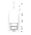
- FIG. 1 shows an external perspective view of the cellular phone 1 in an opened state.
- a mobile phone 1 as a portable electronic device includes an operation unit side case 2 as a first case and a display unit side case 3 as a second case.
- the operation unit side body 2 includes an operation unit side inner surface 2A as a first surface and an operation unit side outer surface 2B as a third surface opposite to the operation unit side inner surface 2A.
- the display unit side body 3 includes a display unit side inner surface 3A as a second surface and a display unit side outer surface 3B as a fourth surface opposite to the display unit side inner surface 3A.
- the operation unit side body 2 and the display unit side body 3 are connected to each other via a connection unit 4 having a hinge mechanism. Specifically, the upper end portion of the operation unit side body 2 and the lower end portion of the display unit side body 3 are connected via a connecting portion 4.
- the display unit side body 3 is disposed at a closed position as a first relative position with respect to the operation unit side body 2, and the operation unit side inner surface 2A and the display unit side inner surface 3A are spaced apart from each other. And the display unit side body 3 is disposed at the open position as the second relative position with respect to the operation unit side body 2 and the operation unit side inner surface 2A and the display unit side inner surface 3A are close to each other.
- the operation unit side body 2 and the display unit side body 3 are connected so as to be openable and closable around an opening / closing axis R so as to be deformable into a closed state where they are stacked and arranged.
- the mobile phone 1 is configured to be able to relatively move the operation unit side body 2 and the display unit side body 3 connected via the connection unit 4. That is, in the mobile phone 1, the operation unit side body 2 and the display unit side body 3 are opened (open state), and the operation unit side body 2 and the display unit side body 3 are folded. It can be changed to (closed state) (deformable).
- the closed state as viewed from the housing is a state in which both housings are arranged so as to overlap each other
- the open state means a state in which both housings are arranged so as not to overlap each other.
- the outer surface of the operation unit side body 2 is composed of a front case 2a and a rear case 2b.
- the operation unit side body 2 includes an operation key group 11 on the front case 2a side (operation unit side inner surface 2A side), and a microphone 12 as a microphone to which a voice uttered by the user of the mobile phone 1 is input. Are configured to be exposed.
- the operation key group 11 includes a function setting operation key 13 for operating various functions such as various settings, a telephone book function, and a mail function, and an input operation key 14 for inputting a telephone number and characters such as mail. And a determination operation key 15 as an operation member for performing determination in various operations, scrolling in the vertical and horizontal directions, and the like.
- Each key constituting the operation key group 11 has a predetermined function according to the open / close state of the operation unit side body 2 and the display unit side body 3, various modes, or the type of the activated application. Assigned (key assignment). Then, when the user presses each key, an operation corresponding to the function assigned to each key is executed.
- the microphone 12 is disposed on the outer end side opposite to the connecting portion 4 side in the longitudinal direction of the operation unit side body 2. That is, the microphone 12 is disposed on one outer end side when the mobile phone 1 is in the open state.
- An interface (not shown) for communicating with an external device is disposed on one side surface of the operation unit side body 2.
- a side key to which a predetermined function is assigned and an interface (not shown) through which an external memory is inserted and removed are arranged on the other side surface of the operation unit side body 2.
- the interface is covered with a cap. Each interface is covered with a cap when not in use.
- the outer surface of the display unit side body 3 includes a front panel 3a, a front case 3b, a rear case 3c, and a rear panel 3d.
- a display unit 21 for displaying various kinds of information on the display unit side inner surface 3A and a speaker 22 as a receiver for outputting the voice of the other party of the call are exposed to the outside. Be placed.
- the display unit 21 includes a liquid crystal panel, a drive circuit that drives the liquid crystal panel, and a light source unit such as a backlight that emits light from the back side of the liquid crystal panel.
- FIG. 2 is an exploded perspective view of members built in the operation unit side body 2.
- FIG. 3 is an exploded perspective view of members built in the display unit side body 3.
- FIG. 4 is a plan view illustrating the loop antenna 100 when the mobile phone 1 is in the open state.
- FIG. 5 is a cross-sectional view taken along line AA illustrating the loop antenna 100 when the mobile phone 1 is in the open state.
- FIG. 6 is a cross-sectional view taken along the line AA illustrating the loop antenna 100 when the mobile phone 1 is in the closed state.
- the operation unit side body 2 includes a front case 2a, a key structure 40, a key substrate 50, a case body 60, a reference potential pattern layer 75, and RF (Radio Frequency for cellular phones).
- a circuit board 70 including various electronic components such as modules, a main antenna unit 90 for wireless communication via an external base station, a loop antenna 100 that forms a loop in an open state, and a rear including a battery lid 2c. Case 2b and battery 80 are provided.
- the front case 2a and the rear case 2b are arranged so that their concave inner surfaces face each other, and are joined so that their outer peripheral edges overlap. Further, the key structure portion 40, the key substrate 50, the case body 60, the circuit board 70, the main antenna portion 90, and the loop antenna 100 are sandwiched between the front case 2a and the rear case 2b. Built in.
- key holes 13a, 14a, and 15a are formed on the inner side surface (the operation unit side inner surface 2A) facing the display unit 21 of the display unit side body 3 in the closed state in which the cellular phone 1 is folded. .
- the pressing surface of the function setting operation key member 13b constituting the function setting operation key 13 the pressing surface of the input operation key member 14b constituting the input operation key 14, and the determination operation key 15
- the pressing surface of the determination operation key member 15b that constitutes is exposed.
- the metal dome described later is provided in each corresponding key switch 51, 52, 53. The apex of (saddle-like shape) is pressed and comes into electrical contact with the switch terminal.
- the key structure unit 40 includes an operation member 40A, a key frame 40B as a reinforcing member, and a key sheet 40C as a sheet member.
- the operation member 40A is composed of a plurality of key operation members. Specifically, it is configured by a function setting operation key member 13b, an input operation key member 14b, and a determination operation key member 15b. Each operation key member constituting the operation member 40A is bonded to the key sheet 40C with a key frame 40B described later interposed therebetween. As described above, the pressing surface of each operation key member bonded to the key sheet 40C is disposed so as to be exposed to the outside from each of the key holes 13a, 14a, 15a.
- the key frame 40B is a metallic plate-like member having a plurality of holes 14c.
- the key frame 40B is a reinforcing member for preventing adverse effects on the circuit board 70 and the like due to the pressing of the input operation key member 14b.
- the key frame 40B is a conductive member, and also functions as a member for releasing static electricity from the input operation key member 14b.
- the plurality of holes 14c formed in the key frame 40B are arranged so that convex portions 14d formed in the key sheet 40C described later are fitted.
- the input operation key member 14b is bonded to the convex portion 14d.
- the key sheet 40C is a flexible sheet-like member made of silicon rubber. As described above, a plurality of convex portions 14d are formed on the key sheet 40C. The plurality of convex portions 14d are formed on the surface of the key sheet 40C on the side where the key frame 40B is disposed. Each of the plurality of convex portions 14d is formed at a position corresponding to a key switch 52 described later.
- the key substrate 50 has a plurality of key switches 51, 52, 53 arranged on the first surface 50a that is the surface on the key sheet 40C side.
- the plurality of key switches 51, 52, 53 are arranged at positions corresponding to the respective operation members 40A.
- the key switches 51, 52 and 53 arranged on the key substrate 50 have a structure having a metal dome of a metal plate which is curved in a bowl shape and is three-dimensionally formed.
- the metal dome is configured to be electrically connected to a switch terminal formed on an electric circuit (not shown) printed on the surface of the key substrate 50 when the apex of the bowl-shaped shape is pressed. Is done.
- a plurality of electrode wirings are formed on the second surface 50 b side of the key substrate 50.
- the case body 60 is a conductive member having a shape in which one wide surface of a thin rectangular parallelepiped is opened.
- the case body 60 includes ribs 62 that are formed substantially perpendicular to the opening-side surface of the flat plate portion 61.
- the rib 62 is formed to be equal to or sufficiently higher than the height of the tallest electronic component among the various electronic components mounted on the circuit board 70.
- the rib 62 is formed so as to correspond to the reference potential pattern layer 75 constituting the reference potential portion on the periphery and inside of the flat plate portion 61. Specifically, the rib 62 is formed so as to be disposed on the reference potential pattern layer 75 in a state where the case body 60 is placed on the circuit board 70.
- the case body 60 may be formed of a metal, a skeleton formed of a resin, and a conductor film formed on the surface thereof.
- the case body 60 is electrically connected to the reference potential pattern layer 75 by contacting the bottom surface of the rib with the reference potential pattern layer 75.
- the case body 60 is electrically connected to the reference potential pattern layer 75 and has the same potential as the reference potential pattern layer 75. That is, the case body 60 functions as a shield case.
- the case body 60 serves as a shield case to suppress external noise such as high frequency from acting on various electronic components disposed on the circuit board 70 and to emit from an RF (Radio Frequency) circuit, a CPU circuit, a power supply circuit, and the like. This prevents the generated noise from acting on other electronic components, a receiving circuit connected to the main antenna unit 90, and the like.
- RF Radio Frequency
- the bottom surface of the rib 62 in the case body 60 is disposed on the reference potential pattern layer 75, so that each circuit described later is surrounded by the rib 62 and covered with a part of the flat plate portion 61.
- the rib 62 functions as a partition wall in each circuit, and shields each circuit together with a part of the flat plate portion 61.
- various electronic components and circuits including a signal processing unit that processes signals transmitted and received by the main antenna unit 90 are arranged on the circuit board 70.
- Various electronic components form a plurality of circuit blocks by a predetermined combination.
- various circuit blocks including an RF (Radio Frequency) circuit, a power supply circuit, and the like are formed.
- RF Radio Frequency
- a reference potential pattern layer 75 constituting a reference potential portion is formed on the first surface 70a of the circuit board 70 on the case body 60 side, in addition to the above-described various electronic components.
- the reference potential pattern layer 75 is formed so as to partition each circuit block described above.
- the reference potential pattern layer 75 is formed by printing a conductive member in a predetermined pattern on the surface of the first surface 70a of the circuit board 70.
- An RFID chip 110 connected to the loop antenna 100 is disposed on the battery-side second surface 70 b of the circuit board 70. The RFID chip 110 is read and written by an external reader / writer device via the loop antenna 100.
- the main antenna unit 90 is configured by arranging an antenna element having a predetermined shape on a base.
- the main antenna unit 90 is disposed on the end side opposite to the connection unit 4 side in the mobile phone 1.
- the antenna element of the main antenna unit 90 is formed of a strip-shaped sheet metal.
- the main antenna unit 90 is supplied with power from the circuit board 70 via a power supply terminal (not shown). As a result, the antenna element is fed from the circuit board 70 via the feed terminal and is connected to the RF module and the like of the circuit board 70.
- the loop antenna 100 is disposed across the operation unit side body 2 and the display unit side body 3. As shown in FIG. 4, the loop antenna 100 includes a sheet unit 102 and a coil unit 104 disposed on the sheet unit 102.
- the sheet part 102 is a sheet-like member made of a PET (polyethylene terephthalate) material, and is a member that can be flexibly deformed.
- the coil portion 104 is formed such that a thin film conductive member is spiral.
- the loop antenna 100 communicates with a reader / writer device (not shown) in a predetermined use frequency band (for example, 13.56 Hz).
- a predetermined use frequency band for example, 13.56 Hz.
- the loop antenna 100 includes at least a part of a first part 100a disposed on the operation unit side body 2 side and a second part 100b disposed on the display unit side body 3 side. It is comprised by the 3rd parts 100c and 100c arrange
- the first part 100 a is disposed on the operation unit side outer surface 2 ⁇ / b> B side of the operation unit side body 2.
- the second part 100b is disposed on the display unit side outer surface 3B side in the display unit side body 3.
- the loop antenna 100 forms a loop.
- the loop antenna 100 forms a loop that spreads in a planar shape.
- the loop antenna 100 has an annular shape spreading in a plane.
- the loop antenna 100 can receive a magnetic field and generate an electromotive force by electromagnetic induction.
- the loop antenna 100 can communicate with a reader / writer device arranged outside.
- the loop antenna 100 is deformed along with the deformation of the mobile phone 1 and does not form a loop.
- the loop antenna 100 is in a state in which the third parts 100c and 100c are curved, and the first part 100a and the second part 100b are arranged to face each other.
- the loop antenna 100 is displayed with the first part 100a disposed on the operation unit side body 2 side in the stacking direction of the operation unit side body 2 and the display unit side body 3. It arrange
- the loop antenna 100 that forms a loop does not form a planar loop when the loop antenna 100 is folded.
- the portion of the first portion 100a of the loop antenna 100 can be seen on the plane as viewed from above in FIG.
- the coil portion 104 (a U-shaped portion) in the first portion 100a can be seen on the plane.
- the connecting portion When the cellular phone 1 in the closed state is brought close to the reader / writer device arranged outside, the connecting portion may be placed close to the operation portion side outer surface 2B or the display portion side outer surface 3B. Even if the four antennas are close to each other, the loop antenna 100 does not form a loop when viewed from the reader / writer device. That is, when the mobile phone 1 is in the closed state, the loop antenna 100 cannot communicate with the reader / writer device arranged outside.
- a detachable battery lid 2c is provided on one end side (in FIG. 2) of the rear case 2b.
- the battery lid 2c is attached to the rear case 2b after storing the battery 80 from the outside of the rear case 2b.
- a microphone 12 (not shown) for inputting the user's voice is accommodated at one end side of the rear case 2b.
- the display unit side body 3 includes a front panel 3a, a speaker 22, a front case 3b, a speaker 22, a display unit 21, and a printed circuit board 85 to which the display unit 21 is connected.
- a rear case 3c and a rear panel 3d are provided.
- the display unit side body 3 includes a front panel 3a, a front case 3b, a display unit 21, a printed circuit board 85, a rear case 3c, and a rear panel 3d that are stacked.
- the front case 3b and the rear case 3c are arranged so that the inner surfaces of the concave shapes face each other, and are joined so that the outer peripheral edges thereof overlap each other.
- the printed circuit board 85 to which the display unit 21 is connected is sandwiched between the front case 3b and the rear case 3c.
- a speaker connected to an amplifier (not shown) is connected to the printed board 85.
- FIG. 7 is a block diagram illustrating a circuit configuration in the mobile phone 1.
- the mobile phone 1 includes a wireless communication unit 200 disposed in the operation unit side body 2, an operation unit 101 as an input unit, a microphone 12, an LCD control unit 42, and a voice processing unit. 43, a memory 44 as a storage unit, a CPU 45, a power supply unit 46, a control IC 47, a loop antenna 100, an RFID chip 110, a display unit 21 arranged in the display unit side body 3, and a speaker 22 And a driver IC 25.
- the wireless communication unit 200 includes a main antenna unit 90 that communicates with an external device in a predetermined use frequency band, and a communication processing unit 201 that performs signal processing such as modulation processing or demodulation processing.
- the main antenna unit 90 communicates with a base station (not shown) in a predetermined use frequency band (for example, 800 MHz).
- the main antenna unit 90 communicates with an external communication device via a base station in a predetermined use frequency band.
- the predetermined use frequency band is 800 MHz, but other frequency bands may be used.
- the main antenna unit 90 may have a so-called dual-band compatible configuration that can support a second used frequency band (for example, 2 GHz) in addition to a predetermined used frequency band (first used frequency band). Furthermore, it may be configured by a multi-band compatible type that can also correspond to the third use frequency band.
- the communication processing unit 201 modulates a signal supplied from a predetermined functional unit, transmits the signal to the base station via the main antenna unit 90, and demodulates a signal received by the main antenna unit 90 to perform a predetermined functional unit. To supply.
- the operation unit 101 includes an operation key group 11.
- the LCD control unit 42 performs predetermined image processing on the input image data under the control of the CPU 45 and outputs the image processed image data to the driver IC 25.
- the driver IC 25 stores the image data input from the LCD control unit 42 in the frame memory, and outputs the image data stored in the frame memory to the display unit 21 at a predetermined timing.
- the display unit 21 displays predetermined characters and images based on data input from the driver IC 25.
- the memory 44 stores predetermined data. Specifically, the memory 44 stores application programs for operating various functions, profile information, address information used for the address book function, and the like.
- CPU 45 controls the entire mobile phone 1. In particular, the CPU 45 performs predetermined control on the wireless communication unit 200, the LCD control unit 42, and the audio processing unit 43.
- the sound processing unit 43 performs predetermined sound processing on the signal supplied from the communication processing unit 201 and outputs the sound-processed signal to the speaker 22 under the control of the CPU 45.
- the speaker 22 emits sound (outputs) to the outside based on the signal supplied from the sound processing unit 43.
- the audio processing unit 43 performs predetermined processing on the signal input from the microphone 12 and outputs the processed signal to the communication processing unit 201 according to the control of the CPU 45.
- the communication processing unit 201 performs predetermined processing on the signal input from the audio processing unit 43 and outputs the processed signal to the main antenna unit 90.
- the power supply unit 46 includes a battery 80.
- the battery 80 is a lithium ion battery having a predetermined capacity.
- the control IC 47 converts the power supply voltage supplied from the power supply unit 46 into a predetermined power supply voltage, and supplies the converted power supply voltage to each unit (for example, the CPU 45) in the mobile phone 1.
- the loop antenna 100 is modulated with respect to a magnetic field (carrier frequency (for example, 13.56 MHz) transmitted from the reader / writer device when approaching a predetermined distance to the reader / writer device arranged outside. ).
- carrier frequency for example, 13.56 MHz
- the RFID chip 110 includes a power supply circuit that generates a predetermined voltage based on power induced by a signal received by the loop antenna 100, and a signal such as a modulation process or a demodulation process for a signal communicated by the loop antenna 100.
- An RF circuit that performs processing, a CPU that performs predetermined arithmetic processing, and a memory that stores predetermined data are provided.
- the power supply circuit is constituted by, for example, a DC-DC converter.
- the power supply circuit generates a predetermined power supply voltage from the electromotive force generated by the electromagnetic induction action when the magnetic field is received by the loop antenna 100, and supplies the power supply voltage to the RF circuit, the CPU, and the memory.
- the RF circuit, the CPU, and the memory shift from the stopped state to the activated state when a predetermined power supply voltage is supplied from the power supply circuit.
- the RF circuit performs signal processing such as demodulation on the signal supplied via the loop antenna 100, and supplies the processed signal to the CPU.
- the RF circuit performs signal processing such as modulation on the data read from the memory and transmits the data to an external reader / writer device via the loop antenna 100.
- the CPU writes data to the memory or reads data from the memory based on the signal supplied from the RF circuit.
- the CPU reads data from the memory, the CPU supplies the data to the RF circuit.
- the loop antenna 100 forms a loop.
- the loop antenna 100 is connected to a reader / writer device arranged outside. Communication is possible. That is, in the open state, the mobile phone 1 is in a state where data can be read from the RFID chip 110 and data can be written to the RFID chip 110.
- the loop antenna 100 does not form a loop, so that the loop antenna 100 cannot communicate with the reader / writer device as described above. . That is, in the closed state, the mobile phone 1 is in a state in which reading of data from the RFID chip 110 and writing of data to the RFID chip 110 are impossible.
- the mobile phone 1 according to the present embodiment can be in a state where communication by the loop antenna 100 is possible / impossible by changing the form (opening / closing state).
- the mobile phone 1 is in a state in which communication by the loop antenna 100 is impossible in a closed state that is a state where the user carries around without using a communication function or the like.
- a mobile phone 1 including a loop antenna 100 that forms a loop when the mobile phone 1 is opened and does not form a loop when the mobile phone 1 is closed is provided.
- a mobile phone 1 is provided in which communication by the loop antenna 100 is possible in the open state and communication by the loop antenna 100 is impossible in the closed state.
- the present embodiment it is possible to switch to a state where communication by the loop antenna 100 is possible or impossible only by changing the open / close state of the mobile phone 1. Thereby, the user can switch to a state where communication by the loop antenna 100 is possible or impossible by a simple operation. Further, since it is possible to switch to a state where communication by the loop antenna 100 is possible or impossible by a simple operation, it is possible to suppress neglecting to switch to a state where communication is not possible due to the conventional reason that the switching work is complicated. The Thereby, reading of information from the RFID chip 110 unintended by the user and writing of information to the RFID chip 110 are suppressed. For example, it is suppressed that charged electronic money is withdrawn without permission.
- the mobile phone 1 since the mobile phone 1 cannot communicate with the loop antenna 100 in the closed state, which is a normal carrying state, the above-described unintended reading / writing of information can be suitably suppressed. . That is, the mobile phone 1 with improved security is provided.
- the mobile phone 1 is described as a mobile electronic device.
- the present invention is not limited to this, but the PHS (registered trademark; Personal Handyphone System), PDA (Personal Digital Assistant), portable navigation device, notebook A personal computer etc. may be sufficient.
- the loop antenna 100 is configured to include a sheet portion 102 and a coil portion 104 in which a thin film-like conductive member disposed on the sheet portion 102 is formed in a spiral shape. It is not limited to this, For example, you may comprise with the coil part by which conducting wire was wound.
- the loop antenna 100 has been described as a passive induction electromagnetic field method (electromagnetic induction method) that does not have a power supply unit. It is not limited.
- the loop antenna 100 (RFID chip 110) may be, for example, a passive mutual induction method (electromagnetic coupling method) or a radiated electromagnetic field method (radio wave method).
- the loop antenna 100 (RFID chip 110) may be, for example, an active type having a power supply unit.
- the external device may be a read only type, a write once type, or the like.
- the cellular phone 1 that can be folded (opened and closed) by the connecting portion 4 is described, but the present invention is not limited to this.
- the display unit side body 3 is disposed at the first relative position with respect to the operation unit side body 2, and the display unit side body 3 is located with respect to the operation unit side body 2.
- What is necessary is just to be comprised so that it can deform
- a slide type in which one housing is slid in one direction from a state in which the body 2 and the display unit side housing 3 are overlapped may be used.
- FIG. 8 is a side view of the mobile phone 1A in the first open state.
- FIG. 9 is a diagram illustrating the arrangement and state of the loop antenna 100 in the first open state.
- FIG. 10 is a side view of the mobile phone 1A in the second open state.
- FIG. 11 is a diagram illustrating the arrangement and state of the loop antenna 100 in the second open state.
- the first open state refers to an open state in which the operation unit side inner surface 2A and the display unit side inner surface 3A face the same side (left side in FIG. 8) in the open state.
- the second open state refers to an open state in which the operation unit side inner surface 2A and the display unit side inner surface 3A face different sides (left side and right side in FIG. 10) in the open state.
- the description of the same configuration as that of the above-described mobile phone 1 opening / closing type
- a description will be given focusing on different configurations.
- the mobile phone 1 ⁇ / b> A includes an operation unit side body 2 and a display unit side body 3.
- the operation unit side body 2 and the display unit side body 3 are coupled via a coupling unit 4 having a biaxial hinge mechanism. Accordingly, the mobile phone 1 can be deformed into an open state and a closed state, and can be switched between the front side state and the back side state in the open state and the closed state.
- the closed state and the open state are as described in the mobile phone 1 described above.
- the mobile phone 1A can be modified so as to switch the front and back of the display unit side body 3 in the open state.
- the operation unit side inner surface 2A and the display unit side inner surface 3A are from the first open state in which the operation unit side inner surface 2A and the display unit side inner surface 3A face the same side (left side in FIG. 8).
- the connecting unit 4 connects the operation unit side body 2 and the display unit side body 3 so as to be openable and closable, and can reverse the front and back of the display unit side body 3 with respect to the operation unit side body 2. Connect as follows. In the open state, the connection unit 4 is configured to be rotatable about the rotation axis S (see FIG. 11) where the display unit side body 3 intersects the opening / closing axis R with respect to the operation unit side body 2. 2 and the display unit side body 3 are connected.
- the loop antenna 100 includes at least one of a first part 100a arranged in the operation unit side body 2 and a second part 100b arranged on the display unit side body 3 side. And a third A portion 100c arranged in the connecting portion 4.
- the third part A100c in the loop antenna 100 is formed to be narrower than the first part 100a and the second part 100b.
- the loop antenna 100 forms a loop.
- the loop antenna 100 forms a loop whose center in the longitudinal direction is recessed (narrowed) inward when viewed from the front in FIG.
- the coil portion 104 constituting the loop antenna 100 forms a loop that is recessed (constricted) in the center in the longitudinal direction when viewed from the front in FIG.
- the loop antenna 100 is twisted in the third A portion 100c.
- the portion disposed in the third portion A100c has a twisted position relationship.
- the loop antenna 100 enters a state in which no loop is formed.
- the coil unit 104 constituting the loop antenna 100 is in a state where no loop is formed.
- the cellular phone 1 ⁇ / b> A is impossible from the state in which communication by the loop antenna 100 is possible by rotating the display unit side body 3 so as to be reversed upside down with respect to the operation unit side body 2. Can be switched to a different state.
- the mobile phone 1A is in a state where communication by the loop antenna 100 is possible only in the first open state.
- the present embodiment it is possible to obtain the same effect as that of the mobile phone 1 described above. Further, according to the present embodiment, communication by the loop antenna 100 is possible only in the first open state, so that security is further improved.
- loop antenna 100 and other forms of the external device type are the same as those of the mobile phone 1.
- FIG. 12 is a side view of the mobile phone 1B in the open state.
- FIG. 13 is a diagram illustrating the arrangement and state of the loop antenna 100 in the open state.
- FIG. 14 is a side view of the mobile phone 1B in the closed state.
- FIG. 15 is a diagram illustrating the arrangement and state of the loop antenna 100 in the closed state.
- the mobile phone 1 ⁇ / b> B includes an operation unit side body 2 and a display unit side body 3 that is stacked on the operation unit side inner surface 2 ⁇ / b> A side of the operation unit side body 2. Is provided.
- the display unit side body 3 is coupled to the operation unit side body 2 so as to be slidable on the operation unit side inner surface 2A.
- the mobile phone 1B includes a connecting unit that connects the operation unit side body 2 and the display unit side body 3 so that the relative positions of the operation unit side body 2 and the display unit side body 3 can be slid. 4B is provided.
- the connection unit 4B connects the operation unit side body 2 and the display unit side body 3 so that the cellular phone 1B can be deformed into an open state and a closed state.
- the display unit side body 3 is disposed at an open position as a first relative position with respect to the operation unit side body 2, and a predetermined region on the operation unit side inner surface 2A is exposed to the outside.
- An open state see FIGS. 12 and 13
- a closed state in which the display unit side body 3 is disposed at a closed position as the second position with respect to the operation unit side body 2 and covers a predetermined region on the operation unit side inner surface 2A.
- the operation unit side body 2 and the display unit side body 3 are slidably coupled so as to be deformable (see FIGS. 14 and 15).
- the loop antenna 100 includes a first part 100 f arranged inside the operation unit side body 2 and a second part 100 g attached to the outer surface of the display unit side body 3. Prepare.
- the loop antenna 100 forms a loop. Specifically, when mobile phone 1B is in the open state, loop antenna 100 forms a loop when viewed from the front in FIG. Specifically, when the cellular phone 1B is in an open state, the coil portion 104 constituting the loop antenna 100 forms a loop when viewed from the front in FIG.
- the loop antenna 100 is arranged so that the first part 100f and the second part 100g overlap each other in the stacking direction of the operation unit side body 2 and the display unit side body 3. In this case, as shown in FIG. 15, the loop antenna 100 does not form a loop. Specifically, in the closed state, the coil unit 104 constituting the loop antenna 100 is in a state where no loop is formed.
- loop antenna 100 and other forms of the external device type are the same as those of the mobile phone 1.
Abstract
Description
例えば、ループアンテナを有し、外部装置とループアンテナとが誘導結合されることにより、情報の読み出しや書き込みが行われる携帯電話機が提案されている(例えば、特許文献1参照)。 In recent years, some mobile phones as portable electronic devices have the same functions as non-contact IC cards.
For example, a mobile phone that has a loop antenna and reads and writes information by inductively coupling an external device and the loop antenna has been proposed (for example, see Patent Document 1).
まず、図1により、携帯電話機1における基本構造を説明する。図1は、携帯電話機1を開いた状態における外観斜視図を示す。 The best mode for carrying out the present invention will be described below with reference to the drawings.
First, the basic structure of the
表示部21は、液晶パネルと、この液晶パネルを駆動する駆動回路と、この液晶パネルの背面側から光を照射するバックライト等の光源部とから構成される。 The outer surface of the display
The
図2は、操作部側筐体2に内蔵される部材の分解斜視図である。図3は、表示部側筐体3に内蔵される部材の分解斜視図である。図4は、携帯電話機1が開状態におけるループアンテナ100を説明する平面図である。図5は、携帯電話機1が開状態におけるループアンテナ100を説明するA-A断面図である。図6は、携帯電話機1が閉状態におけるループアンテナ100を説明するA-A断面図である。 Next, the internal structure of the operation
FIG. 2 is an exploded perspective view of members built in the operation
図4に示すように、ループアンテナ100は、シート部102と、シート部102に配置されるコイル部104と備える。 As shown in FIGS. 4 to 6, the
As shown in FIG. 4, the
コイル部104は、薄膜状の導電性部材が渦巻状になるようにして形成される。 The
The
つまり、携帯電話機1が閉状態の場合において、ループアンテナ100は外部に配置されるリーダ・ライタ装置との通信が不可能である。 When the
That is, when the
図7は、携帯電話機1における回路構成を説明するブロック図である。
図7に示すように、携帯電話機1は、操作部側筐体2に配置される無線通信部200と、入力部としての操作部101と、マイク12と、LCD制御部42と、音声処理部43と、記憶部としてのメモリ44と、CPU45と、電源部46と、制御IC47と、ループアンテナ100と、RFIDチップ110と、表示部側筐体3に配置される表示部21と、スピーカ22と、ドライバIC25とを備える。 Next, the circuit configuration of the
FIG. 7 is a block diagram illustrating a circuit configuration in the
As shown in FIG. 7, the
操作部101は、操作キー群11を含んで構成される。 The communication processing unit 201 modulates a signal supplied from a predetermined functional unit, transmits the signal to the base station via the
The
表示部21は、ドライバIC25から入力されたデータに基づいて、所定の文字や画像を表示する。 The
The
電源回路は、ループアンテナ100により磁界が受信されることで電磁誘導作用により発生した起電力から所定の電源電圧を生成し、RF回路と、CPUと、メモリとに供給する。RF回路と、CPUと、メモリとは、電源回路から所定の電源電圧が供給されることにより停止状態から起動状態に移行する。 The power supply circuit is constituted by, for example, a DC-DC converter.
The power supply circuit generates a predetermined power supply voltage from the electromotive force generated by the electromagnetic induction action when the magnetic field is received by the
RF回路は、メモリから読み出されたデータに対して変調等の信号処理を行い、ループアンテナ100を介して外部のリーダ・ライタ装置に送信する。 The RF circuit performs signal processing such as demodulation on the signal supplied via the
The RF circuit performs signal processing such as modulation on the data read from the memory and transmits the data to an external reader / writer device via the
また、外部装置は、リード・ライト型のほか、リードオンリー型や、ライトワンス型等であってもよい。 In the present embodiment, the loop antenna 100 (RFID chip 110) has been described as a passive induction electromagnetic field method (electromagnetic induction method) that does not have a power supply unit. It is not limited. The loop antenna 100 (RFID chip 110) may be, for example, a passive mutual induction method (electromagnetic coupling method) or a radiated electromagnetic field method (radio wave method). The loop antenna 100 (RFID chip 110) may be, for example, an active type having a power supply unit.
In addition to the read / write type, the external device may be a read only type, a write once type, or the like.
まず、図8から図11により、携帯電話機が2軸ヒンジタイプである場合の実施形態について説明する。
図8は、第1開状態における携帯電話機1Aの側面図である。図9は、第1開状態におけるループアンテナ100の配置及び状態を説明する図である。図10は、第2開状態における携帯電話機1Aの側面図である。図11は、第2開状態におけるループアンテナ100の配置及び状態を説明する図である。ここで、第1開状態とは、開状態において操作部側内面2Aと表示部側内面3Aとが同じ側(図8において左側)を向く開状態をいう。第2開状態とは、開状態において操作部側内面2Aと表示部側内面3Aとが異なる側(図10において左側と右側)を向く開状態をいう。
以下、上述した携帯電話機1(開閉タイプ)と同様の構成については説明を省略し、異なる構成を中心に説明をする。 Hereinafter, biaxial hinge type and slide type embodiments will be described.
First, an embodiment when the mobile phone is of a biaxial hinge type will be described with reference to FIGS.
FIG. 8 is a side view of the
Hereinafter, the description of the same configuration as that of the above-described mobile phone 1 (opening / closing type) will be omitted, and a description will be given focusing on different configurations.
ここで、閉状態及び開状態は、上述の携帯電話機1における説明の通りである。 As shown in FIGS. 8 to 11, the
Here, the closed state and the open state are as described in the
連結部4は、開状態において、操作部側筐体2に対して表示部側筐体3が開閉軸Rと交差する回転軸S(図11参照)を中心に回転可能に操作部側筐体2と表示部側筐体3とを連結する。 The connecting
In the open state, the
また、携帯電話機1Aは、第1開状態においてのみ、ループアンテナ100による通信が可能な状態となる。 As described above, in the open state, the
In addition, the
また、本実施形態によれば、第1開状態においてのみ、ループアンテナ100による通信が可能となるので、セキュリティがより向上される。 According to the present embodiment, it is possible to obtain the same effect as that of the
Further, according to the present embodiment, communication by the
図12は、開状態における携帯電話機1Bの側面図である。図13は、開状態におけるループアンテナ100の配置及び状態を説明する図である。図14は、閉状態における携帯電話機1Bの側面図である。図15は、閉状態におけるループアンテナ100の配置及び状態を説明する図である。
以下、上述した携帯電話機1(開閉タイプ)と同様の構成については説明を省略し、異なる構成を中心に説明をする。 Next, an embodiment in which the mobile phone is a slide type will be described with reference to FIGS.
FIG. 12 is a side view of the
Hereinafter, the description of the same configuration as that of the above-described mobile phone 1 (opening / closing type) will be omitted, and a description will be given focusing on different configurations.
2 操作部側筐体
2A 操作部側内面
3 表示部側筐体
3A 表示部側内面
4 連結部
100 ループアンテナ
100a 第1部
100b 第2部
100c 第3部、第3A部
102 シート部
104 コイル部
S 開閉軸
R 回転軸 DESCRIPTION OF
Claims (13)
- 第1筐体と、
第2筐体と、
第1状態及び第2状態に変形可能となるように前記第1筐体と前記第2筐体とを連結する連結部と、
前記第1筐体及び前記第2筐体に配置され、前記第1状態においてループを形成すると共に前記第2状態においてループを形成しないように変形されるアンテナと、を備える
携帯電子機器。 A first housing;
A second housing;
A connecting portion that connects the first housing and the second housing so as to be deformable into a first state and a second state;
A portable electronic device comprising: an antenna that is disposed in the first housing and the second housing and is deformed so as to form a loop in the first state and not form a loop in the second state. - 前記第2状態は、前記第1筐体と前記第2筐体とが互いに積層された状態であり、
前記アンテナは、前記第1筐体に配置される第1部と、前記第2筐体に配置される第2部とを有し、
前記第2状態において、前記アンテナが湾曲するように変形して、前記第1部と前記第2部とは、前記第1筐体と前記第2筐体との積層方向において互いに重なるように配置される
請求項1に記載の携帯電子機器。 The second state is a state in which the first housing and the second housing are stacked on each other,
The antenna has a first part arranged in the first casing and a second part arranged in the second casing,
In the second state, the antenna is deformed so as to be bent, and the first part and the second part are arranged to overlap each other in the stacking direction of the first casing and the second casing. The portable electronic device according to claim 1. - 第1面を有する第1筐体と、
第2面を有する第2筐体と、
前記第1面と前記第2面とが互いに離間して配置される開状態と、前記第1面と前記第2面とが互いに近接した状態で積層して配置される閉状態とに変形可能に前記第1筐体と前記第2筐体とを開閉軸を中心に開閉可能に連結する連結部と、
前記第1筐体及び前記第2筐体に配置され、前記開状態においてループを形成すると共に前記閉状態においてループを形成しないように変形されるアンテナと、を備える
携帯電子機器。 A first housing having a first surface;
A second housing having a second surface;
Deformable into an open state in which the first surface and the second surface are spaced apart from each other, and a closed state in which the first surface and the second surface are stacked and disposed in proximity to each other A connecting portion that connects the first housing and the second housing so as to be openable and closable around an opening and closing shaft;
A portable electronic device comprising: an antenna that is disposed in the first housing and the second housing and is deformed so as to form a loop in the open state and not form a loop in the closed state. - 前記アンテナは、前記第1筐体に配置される第1部と、前記第2筐体に配置される第2部とを有し、
前記閉状態において、前記アンテナが湾曲するように変形して、前記第1部と前記第2部とは、前記第1筐体と前記第2筐体との積層方向において互いに重なるように配置される
請求項3に記載の携帯電子機器。 The antenna has a first part arranged in the first casing and a second part arranged in the second casing,
In the closed state, the antenna is deformed so as to be bent, and the first part and the second part are arranged to overlap each other in the stacking direction of the first casing and the second casing. The portable electronic device according to claim 3. - 前記アンテナは、前記第1部と前記第2部とをつなぐように形成されると共に、前記湾曲するように変形する部分である第3部を有する
請求項4に記載の携帯電子機器。 5. The portable electronic device according to claim 4, wherein the antenna is formed so as to connect the first part and the second part, and has a third part that is a part that is deformed so as to be bent. - 前記アンテナは、
前記第1部が前記第1面側に配置されると共に前記第2部が前記第2面側に配置されるか、又は、
前記第1部が前記第1筐体における前記第1面と反対側の第3面側に配置されると共に前記第2部が前記第2筐体における前記第2面と反対側の第4面側に配置される
請求項4に記載の携帯電子機器。 The antenna is
The first part is disposed on the first surface side and the second part is disposed on the second surface side, or
The first part is disposed on a third surface side opposite to the first surface in the first housing, and the second part is a fourth surface opposite to the second surface in the second housing. The portable electronic device of Claim 4 arrange | positioned at the side. - 前記連結部は、前記第1筐体に対して前記第2筐体が前記開閉軸と交差する回転軸を中心に回転可能に前記第1筐体と前記第2筐体を連結し、
前記第2筐体が前記回転軸を中心に回転され前記第2面が反対側を向くように回転された場合、前記アンテナは、捩れるように変形して、前記開状態であってもループを形成しない
請求項3に記載の携帯電子機器。 The connecting portion connects the first housing and the second housing so that the second housing can rotate around a rotation axis intersecting the opening / closing axis with respect to the first housing,
When the second casing is rotated around the rotation axis and rotated so that the second surface faces the opposite side, the antenna is deformed to be twisted and loops even in the open state. The portable electronic device according to claim 3, wherein the portable electronic device is not formed. - 前記アンテナは、前記第1部と前記第2部とをつなぐように形成されると共に、前記捩れるように変形する部分である第3A部を有する
請求項7に記載の携帯電子機器。 8. The portable electronic device according to claim 7, wherein the antenna is formed so as to connect the first part and the second part, and has a third A part that is a part that deforms so as to be twisted. 9. - 前記第3A部は、前記第1部及び前記第2部より幅が狭くなるよう形成される
請求項8に記載の携帯電子機器。 The portable electronic device according to claim 8, wherein the third A part is formed to be narrower than the first part and the second part. - 第1面を有する第1筐体と、
前記第1筐体における前記第1面側に積層して配置される第2筐体と、
前記第1面における所定領域を外部に露出させる開状態及び前記所定領域を覆う閉状態に変形可能となるように前記第1筐体と前記第2筐体とをスライド移動可能に連結する連結部と、
前記第1筐体及び前記第2筐体に配置され、前記開状態においてループを形成すると共に前記閉状態においてループを形成しないように変形されるアンテナと、を備える
携帯電子機器。 A first housing having a first surface;
A second housing disposed in a stacked manner on the first surface side of the first housing;
A connecting portion that slidably connects the first housing and the second housing so as to be deformed into an open state in which a predetermined region on the first surface is exposed to the outside and a closed state that covers the predetermined region. When,
A portable electronic device comprising: an antenna that is disposed in the first housing and the second housing and is deformed so as to form a loop in the open state and not form a loop in the closed state. - 前記アンテナは、前記第1筐体に配置される第1部と、前記第2筐体に配置される第2部とを有し、
前記閉状態において、前記アンテナが湾曲するように変形して、前記第1部と前記第2部とは、前記第1筐体と前記第2筐体との積層方向において互いに重なるように配置される
請求項10に記載の携帯電子機器。 The antenna has a first part arranged in the first casing and a second part arranged in the second casing,
In the closed state, the antenna is deformed so as to be bent, and the first part and the second part are arranged to overlap each other in the stacking direction of the first casing and the second casing. The portable electronic device according to claim 10. - 前記アンテナは、
前記第1部が前記第1筐体における内部に配置され、
前記第2部が前記第2筐体における外面に取り付けられる
請求項11に記載の携帯電子機器。 The antenna is
The first part is disposed inside the first housing;
The portable electronic device according to claim 11, wherein the second part is attached to an outer surface of the second housing. - 前記アンテナが、前記ループを形成したときに、前記アンテナを介しての外部装置との通信が行われ、
前記アンテナが、前記ループを形成しないときに、前記アンテナを介しての外部装置との通信が不可能となる請求項1に記載の携帯電子機器。 When the antenna forms the loop, communication with an external device via the antenna is performed,
The portable electronic device according to claim 1, wherein communication with an external device via the antenna becomes impossible when the antenna does not form the loop.
Priority Applications (3)
| Application Number | Priority Date | Filing Date | Title |
|---|---|---|---|
| CN200980146637.9A CN102224635B (en) | 2008-11-26 | 2009-11-26 | Portable electronic device |
| KR1020117014524A KR101276412B1 (en) | 2008-11-26 | 2009-11-26 | Portable electronic device |
| US13/131,567 US8791870B2 (en) | 2008-11-26 | 2009-11-26 | Portable electronic device |
Applications Claiming Priority (2)
| Application Number | Priority Date | Filing Date | Title |
|---|---|---|---|
| JP2008-301189 | 2008-11-26 | ||
| JP2008301189A JP5027784B2 (en) | 2008-11-26 | 2008-11-26 | Portable electronic devices |
Publications (1)
| Publication Number | Publication Date |
|---|---|
| WO2010061610A1 true WO2010061610A1 (en) | 2010-06-03 |
Family
ID=42225495
Family Applications (1)
| Application Number | Title | Priority Date | Filing Date |
|---|---|---|---|
| PCT/JP2009/006396 WO2010061610A1 (en) | 2008-11-26 | 2009-11-26 | Portable electronic device |
Country Status (5)
| Country | Link |
|---|---|
| US (1) | US8791870B2 (en) |
| JP (1) | JP5027784B2 (en) |
| KR (1) | KR101276412B1 (en) |
| CN (1) | CN102224635B (en) |
| WO (1) | WO2010061610A1 (en) |
Cited By (1)
| Publication number | Priority date | Publication date | Assignee | Title |
|---|---|---|---|---|
| JP2012129975A (en) * | 2010-11-26 | 2012-07-05 | Kyocera Corp | Portable electronic apparatus |
Families Citing this family (3)
| Publication number | Priority date | Publication date | Assignee | Title |
|---|---|---|---|---|
| US20140227969A1 (en) * | 2013-02-11 | 2014-08-14 | Lsi Corporation | Indium tin oxide loop antenna for near field communication |
| KR20150004521A (en) * | 2013-07-03 | 2015-01-13 | 삼성전자주식회사 | Portable electronic device with antenna device |
| CN116368686A (en) * | 2020-10-12 | 2023-06-30 | 三星电子株式会社 | Electronic device and method for improving antenna efficiency |
Citations (4)
| Publication number | Priority date | Publication date | Assignee | Title |
|---|---|---|---|---|
| JP2004005494A (en) * | 2002-03-25 | 2004-01-08 | Hitachi Kokusai Electric Inc | Ic card and ic card system |
| JP2005217917A (en) * | 2004-01-30 | 2005-08-11 | Toshiba Corp | Portable radio communication device and antenna |
| JP2006148462A (en) * | 2004-11-18 | 2006-06-08 | Nec Corp | Rfid tag |
| JP2007006029A (en) * | 2005-06-22 | 2007-01-11 | Sony Corp | Electronic equipment with built-in rfid |
Family Cites Families (7)
| Publication number | Priority date | Publication date | Assignee | Title |
|---|---|---|---|---|
| US6011519A (en) * | 1998-11-11 | 2000-01-04 | Ericsson, Inc. | Dipole antenna configuration for mobile terminal |
| US20030129950A1 (en) * | 2002-01-10 | 2003-07-10 | Min-Woo Kwak | Antenna of wireless phone |
| EP1445821A1 (en) * | 2003-02-06 | 2004-08-11 | Matsushita Electric Industrial Co., Ltd. | Portable radio communication apparatus provided with a boom portion |
| JP2005341027A (en) * | 2004-05-25 | 2005-12-08 | Nec Saitama Ltd | Mobile communication terminal and forming method thereof |
| JP4331072B2 (en) | 2004-08-27 | 2009-09-16 | パナソニック株式会社 | Portable radio |
| US7362275B2 (en) * | 2006-02-14 | 2008-04-22 | Palm, Inc. | Internal antenna and motherboard architecture |
| JP4722774B2 (en) | 2006-06-19 | 2011-07-13 | 京セラ株式会社 | Electronics |
-
2008
- 2008-11-26 JP JP2008301189A patent/JP5027784B2/en not_active Expired - Fee Related
-
2009
- 2009-11-26 WO PCT/JP2009/006396 patent/WO2010061610A1/en active Application Filing
- 2009-11-26 KR KR1020117014524A patent/KR101276412B1/en active IP Right Grant
- 2009-11-26 CN CN200980146637.9A patent/CN102224635B/en not_active Expired - Fee Related
- 2009-11-26 US US13/131,567 patent/US8791870B2/en not_active Expired - Fee Related
Patent Citations (4)
| Publication number | Priority date | Publication date | Assignee | Title |
|---|---|---|---|---|
| JP2004005494A (en) * | 2002-03-25 | 2004-01-08 | Hitachi Kokusai Electric Inc | Ic card and ic card system |
| JP2005217917A (en) * | 2004-01-30 | 2005-08-11 | Toshiba Corp | Portable radio communication device and antenna |
| JP2006148462A (en) * | 2004-11-18 | 2006-06-08 | Nec Corp | Rfid tag |
| JP2007006029A (en) * | 2005-06-22 | 2007-01-11 | Sony Corp | Electronic equipment with built-in rfid |
Cited By (1)
| Publication number | Priority date | Publication date | Assignee | Title |
|---|---|---|---|---|
| JP2012129975A (en) * | 2010-11-26 | 2012-07-05 | Kyocera Corp | Portable electronic apparatus |
Also Published As
| Publication number | Publication date |
|---|---|
| JP2010130201A (en) | 2010-06-10 |
| CN102224635A (en) | 2011-10-19 |
| US20110273346A1 (en) | 2011-11-10 |
| US8791870B2 (en) | 2014-07-29 |
| CN102224635B (en) | 2014-09-10 |
| KR20110096133A (en) | 2011-08-29 |
| KR101276412B1 (en) | 2013-06-19 |
| JP5027784B2 (en) | 2012-09-19 |
Similar Documents
| Publication | Publication Date | Title |
|---|---|---|
| JP4937989B2 (en) | Portable electronic devices | |
| JP5150467B2 (en) | Portable electronic devices | |
| JP5027784B2 (en) | Portable electronic devices | |
| JP5166070B2 (en) | Electronics | |
| JP5524670B2 (en) | Portable wireless terminal device | |
| JP5675499B2 (en) | Portable electronic devices | |
| JP4335066B2 (en) | Communication terminal | |
| WO2006043543A1 (en) | Noncontact communication antenna and portable mobile terminal | |
| JP5009128B2 (en) | Portable electronic devices | |
| JP2008211598A (en) | Communication equipment | |
| JPWO2010061641A1 (en) | Mobile device | |
| JP4819773B2 (en) | Portable device | |
| JP5361654B2 (en) | Electronics | |
| JP2009239683A (en) | Communication equipment | |
| JP4926904B2 (en) | Communication equipment | |
| JP2008182592A (en) | Portable terminal device | |
| JP2010199252A (en) | Circuit device and electronic apparatus | |
| JP2010232903A (en) | Mobile electronic apparatus | |
| JP2009246548A (en) | Electronic device |
Legal Events
| Date | Code | Title | Description |
|---|---|---|---|
| WWE | Wipo information: entry into national phase |
Ref document number: 200980146637.9 Country of ref document: CN |
|
| 121 | Ep: the epo has been informed by wipo that ep was designated in this application |
Ref document number: 09828860 Country of ref document: EP Kind code of ref document: A1 |
|
| NENP | Non-entry into the national phase |
Ref country code: DE |
|
| ENP | Entry into the national phase |
Ref document number: 20117014524 Country of ref document: KR Kind code of ref document: A |
|
| WWE | Wipo information: entry into national phase |
Ref document number: 13131567 Country of ref document: US |
|
| 122 | Ep: pct application non-entry in european phase |
Ref document number: 09828860 Country of ref document: EP Kind code of ref document: A1 |