WO2010058530A1 - Sliding member and process for producing same - Google Patents
Sliding member and process for producing same Download PDFInfo
- Publication number
- WO2010058530A1 WO2010058530A1 PCT/JP2009/005896 JP2009005896W WO2010058530A1 WO 2010058530 A1 WO2010058530 A1 WO 2010058530A1 JP 2009005896 W JP2009005896 W JP 2009005896W WO 2010058530 A1 WO2010058530 A1 WO 2010058530A1
- Authority
- WO
- WIPO (PCT)
- Prior art keywords
- carbon
- lubricating film
- sliding
- sliding member
- fullerene
- Prior art date
Links
Images


Classifications
-
- F—MECHANICAL ENGINEERING; LIGHTING; HEATING; WEAPONS; BLASTING
- F16—ENGINEERING ELEMENTS AND UNITS; GENERAL MEASURES FOR PRODUCING AND MAINTAINING EFFECTIVE FUNCTIONING OF MACHINES OR INSTALLATIONS; THERMAL INSULATION IN GENERAL
- F16C—SHAFTS; FLEXIBLE SHAFTS; ELEMENTS OR CRANKSHAFT MECHANISMS; ROTARY BODIES OTHER THAN GEARING ELEMENTS; BEARINGS
- F16C33/00—Parts of bearings; Special methods for making bearings or parts thereof
- F16C33/02—Parts of sliding-contact bearings
- F16C33/04—Brasses; Bushes; Linings
- F16C33/043—Sliding surface consisting mainly of ceramics, cermets or hard carbon, e.g. diamond like carbon [DLC]
-
- C—CHEMISTRY; METALLURGY
- C01—INORGANIC CHEMISTRY
- C01B—NON-METALLIC ELEMENTS; COMPOUNDS THEREOF; METALLOIDS OR COMPOUNDS THEREOF NOT COVERED BY SUBCLASS C01C
- C01B32/00—Carbon; Compounds thereof
- C01B32/05—Preparation or purification of carbon not covered by groups C01B32/15, C01B32/20, C01B32/25, C01B32/30
-
- C—CHEMISTRY; METALLURGY
- C10—PETROLEUM, GAS OR COKE INDUSTRIES; TECHNICAL GASES CONTAINING CARBON MONOXIDE; FUELS; LUBRICANTS; PEAT
- C10M—LUBRICATING COMPOSITIONS; USE OF CHEMICAL SUBSTANCES EITHER ALONE OR AS LUBRICATING INGREDIENTS IN A LUBRICATING COMPOSITION
- C10M103/00—Lubricating compositions characterised by the base-material being an inorganic material
- C10M103/02—Carbon; Graphite
-
- C—CHEMISTRY; METALLURGY
- C23—COATING METALLIC MATERIAL; COATING MATERIAL WITH METALLIC MATERIAL; CHEMICAL SURFACE TREATMENT; DIFFUSION TREATMENT OF METALLIC MATERIAL; COATING BY VACUUM EVAPORATION, BY SPUTTERING, BY ION IMPLANTATION OR BY CHEMICAL VAPOUR DEPOSITION, IN GENERAL; INHIBITING CORROSION OF METALLIC MATERIAL OR INCRUSTATION IN GENERAL
- C23C—COATING METALLIC MATERIAL; COATING MATERIAL WITH METALLIC MATERIAL; SURFACE TREATMENT OF METALLIC MATERIAL BY DIFFUSION INTO THE SURFACE, BY CHEMICAL CONVERSION OR SUBSTITUTION; COATING BY VACUUM EVAPORATION, BY SPUTTERING, BY ION IMPLANTATION OR BY CHEMICAL VAPOUR DEPOSITION, IN GENERAL
- C23C14/00—Coating by vacuum evaporation, by sputtering or by ion implantation of the coating forming material
- C23C14/06—Coating by vacuum evaporation, by sputtering or by ion implantation of the coating forming material characterised by the coating material
- C23C14/0605—Carbon
-
- C—CHEMISTRY; METALLURGY
- C23—COATING METALLIC MATERIAL; COATING MATERIAL WITH METALLIC MATERIAL; CHEMICAL SURFACE TREATMENT; DIFFUSION TREATMENT OF METALLIC MATERIAL; COATING BY VACUUM EVAPORATION, BY SPUTTERING, BY ION IMPLANTATION OR BY CHEMICAL VAPOUR DEPOSITION, IN GENERAL; INHIBITING CORROSION OF METALLIC MATERIAL OR INCRUSTATION IN GENERAL
- C23C—COATING METALLIC MATERIAL; COATING MATERIAL WITH METALLIC MATERIAL; SURFACE TREATMENT OF METALLIC MATERIAL BY DIFFUSION INTO THE SURFACE, BY CHEMICAL CONVERSION OR SUBSTITUTION; COATING BY VACUUM EVAPORATION, BY SPUTTERING, BY ION IMPLANTATION OR BY CHEMICAL VAPOUR DEPOSITION, IN GENERAL
- C23C16/00—Chemical coating by decomposition of gaseous compounds, without leaving reaction products of surface material in the coating, i.e. chemical vapour deposition [CVD] processes
- C23C16/22—Chemical coating by decomposition of gaseous compounds, without leaving reaction products of surface material in the coating, i.e. chemical vapour deposition [CVD] processes characterised by the deposition of inorganic material, other than metallic material
- C23C16/26—Deposition of carbon only
-
- F—MECHANICAL ENGINEERING; LIGHTING; HEATING; WEAPONS; BLASTING
- F16—ENGINEERING ELEMENTS AND UNITS; GENERAL MEASURES FOR PRODUCING AND MAINTAINING EFFECTIVE FUNCTIONING OF MACHINES OR INSTALLATIONS; THERMAL INSULATION IN GENERAL
- F16C—SHAFTS; FLEXIBLE SHAFTS; ELEMENTS OR CRANKSHAFT MECHANISMS; ROTARY BODIES OTHER THAN GEARING ELEMENTS; BEARINGS
- F16C33/00—Parts of bearings; Special methods for making bearings or parts thereof
- F16C33/02—Parts of sliding-contact bearings
- F16C33/04—Brasses; Bushes; Linings
- F16C33/06—Sliding surface mainly made of metal
- F16C33/10—Construction relative to lubrication
- F16C33/1095—Construction relative to lubrication with solids as lubricant, e.g. dry coatings, powder
-
- C—CHEMISTRY; METALLURGY
- C10—PETROLEUM, GAS OR COKE INDUSTRIES; TECHNICAL GASES CONTAINING CARBON MONOXIDE; FUELS; LUBRICANTS; PEAT
- C10M—LUBRICATING COMPOSITIONS; USE OF CHEMICAL SUBSTANCES EITHER ALONE OR AS LUBRICATING INGREDIENTS IN A LUBRICATING COMPOSITION
- C10M2201/00—Inorganic compounds or elements as ingredients in lubricant compositions
- C10M2201/04—Elements
- C10M2201/041—Carbon; Graphite; Carbon black
- C10M2201/0413—Carbon; Graphite; Carbon black used as base material
-
- C—CHEMISTRY; METALLURGY
- C10—PETROLEUM, GAS OR COKE INDUSTRIES; TECHNICAL GASES CONTAINING CARBON MONOXIDE; FUELS; LUBRICANTS; PEAT
- C10N—INDEXING SCHEME ASSOCIATED WITH SUBCLASS C10M RELATING TO LUBRICATING COMPOSITIONS
- C10N2030/00—Specified physical or chemical properties which is improved by the additive characterising the lubricating composition, e.g. multifunctional additives
- C10N2030/06—Oiliness; Film-strength; Anti-wear; Resistance to extreme pressure
-
- C—CHEMISTRY; METALLURGY
- C10—PETROLEUM, GAS OR COKE INDUSTRIES; TECHNICAL GASES CONTAINING CARBON MONOXIDE; FUELS; LUBRICANTS; PEAT
- C10N—INDEXING SCHEME ASSOCIATED WITH SUBCLASS C10M RELATING TO LUBRICATING COMPOSITIONS
- C10N2030/00—Specified physical or chemical properties which is improved by the additive characterising the lubricating composition, e.g. multifunctional additives
- C10N2030/12—Inhibition of corrosion, e.g. anti-rust agents or anti-corrosives
-
- C—CHEMISTRY; METALLURGY
- C10—PETROLEUM, GAS OR COKE INDUSTRIES; TECHNICAL GASES CONTAINING CARBON MONOXIDE; FUELS; LUBRICANTS; PEAT
- C10N—INDEXING SCHEME ASSOCIATED WITH SUBCLASS C10M RELATING TO LUBRICATING COMPOSITIONS
- C10N2040/00—Specified use or application for which the lubricating composition is intended
- C10N2040/25—Internal-combustion engines
Definitions
- the present invention relates to a sliding member having a sliding surface that slides on a mating member and a method of manufacturing the same, and more particularly to improvement of the sliding surface for reducing friction with the mating member.
- a lubricating film is formed on the sliding surface that slides with the other member, and the carbon-based molecule having a hollow structure capable of rolling is formed on the lubricating film as a single substance or a group of single substances It is characterized by being contained.
- the sliding member of the present invention when local solid contact occurs at the sliding interface due to the application of high surface pressure between the members, microscopic abrasion occurs on the sliding surface of the sliding member.
- carbon-based molecules having a rollable hollow structure are contained as a single substance or an aggregate of the single substance. Therefore, carbon-based molecules are supplied to the sliding interface by being exposed from the lubricating film by the above-mentioned microscopic wear and part of which is released therefrom. Since such carbon-based molecules have a rollable hollow structure, they act as molecular level ball bearings at the sliding interface.
- the sliding member of the present invention can use various configurations.
- the lubricating film is preferably a DLC film.
- DLC has low friction of its material itself, high hardness (good wear resistance), high chemical stability (good corrosion resistance), weak adhesion (good seizure resistance) Since it is), the sliding characteristic becomes good.
- DLC is composed of harmless carbon and hydrogen as main components, it can satisfy environmental compatibility, and the amount of the raw material (hydrocarbon gas or graphite) is large and stable.
- At least one of fullerene, carbon nanotube, adamantane, a hydrogen compound of fullerene, a hydrogen compound of carbon nanotube, and a hydrogen compound of adamantane can be used.
- fullerene C 60 fullerene can be used.
- the sliding member of the present invention When the sliding member of the present invention is applied to, for example, an engine, it can be used as a sliding member in a cylinder bore or a piston.
- the mating member When a cylinder bore is used as the sliding member, the mating member is a piston, and when using a piston as the sliding member, the mating member is a cylinder bore.
- the lubricating film of the present invention may be applied not only to the sliding member but also to the other member.
- the method of manufacturing a sliding member according to the present invention includes a lubricating film forming step of forming a lubricating film on a sliding surface sliding on a mating member by plasma treatment of a raw material of the lubricating film, and in the lubricating film forming step, A carbon-based molecule gas containing at least one of a carbon-based molecule having a movable hollow structure and a hydrogenated carbon-based molecule is introduced into the raw material plasma to ionize the carbon-based molecule gas, and At the time of deposition of the raw material on the sliding surface, it is characterized in that the ionized carbon-based molecular gas is taken into the lubricating film to be molecularized.
- the manufacturing method of the sliding member of the present invention can obtain the same effect as the sliding member of the present invention.
- carbon-based molecules having a rollable hollow structure are supplied from the lubricating film to the sliding interface due to microscopic wear with the other member, and there Act as a ball bearing.
- FIG. 1 represents the state near the sliding interface of the sliding member of FIG. 1 sliding with the other member
- (A) is a fluid lubrication state where lubricating oil intervenes at the sliding interface
- (B) is a local solid at the sliding interface
- FIG. (A) represents the state near the sliding interface of the sliding member of FIG. 1 sliding with the other member
- (A) is a fluid lubrication state where lubricating oil intervenes at the sliding interface
- (B) is a local solid at the sliding interface
- FIG. 1 is a side sectional view showing a schematic configuration of a sliding member 1 according to an embodiment of the present invention.
- the sliding member 1 includes a main body 10, and a lubricating film 11 is formed on the surface of the main body 10. Inside the lubricating film 11, carbon-based molecules 12 having a rollable hollow structure are contained in a dispersed manner.
- the lubricating film 11 is a DLC film made of, for example, Diamond-Like Carbon (DLC), and its film thickness is, for example, 3 ⁇ m.
- the lubricating film 11 is not limited to the DLC film, and various modifications are possible.
- a dry coating film made of CrN, TiCN, TiAlN or the like, or a plating film of Ni or the like may be used.
- DLC has low friction of the material itself, high hardness (good wear resistance), high chemical stability (good corrosion resistance) and weak adhesion (good seizure resistance). Moreover, since DLC is composed of harmless carbon and hydrogen as main components, it can satisfy environmental compatibility, and the amount of the raw material (hydrocarbon gas or graphite) is large and stable. Specifically, DLC has lower friction than CrN having the same corrosion resistance as compared to the other materials. In addition, DLC is superior to Ni plating in any of the above characteristics.
- DLC is preferable because it has various merits as a lubricating film as compared with the other materials described above.
- fullerene is used as the carbon-based molecule 12
- the DLC film acts as a nanoscale gear (nanogear) at the contact point with the fullerene, Contribute to low friction.
- the carbon-based molecule 12 is released from the lubricating film 11 to the sliding surface at the time of local solid contact with the partner member (not shown) of the lubricating film 11, and acts as a molecular bearing there.
- the carbon-based molecule 12 may be present as a single molecule as shown in FIG. 6 (A), or as shown in FIG. 6 (B), the carbon-based molecule 12 is present as an aggregate composed of plural molecules. It may be In FIG. 6, the molecule of the carbon-based molecule 12 is shown in a simplified manner for the convenience of illustration.
- the carbon-based molecule 12 contained in the lubricating film 11 is an allotrope of carbon synthesized by a large number of carbon atoms, and is a spherical molecule (eg, C-like molecule having no anisotropy in the rolling direction with respect to external load) 60 fullerene) or its hydrogen compound is most desirable.
- it may be a pseudo-spherical body having a closed structure (for example, higher fullerenes such as C 70 , C 74 and C 76 , adamantane (Adamantane, C 10 H 16 ), or a hydrogen compound thereof).
- they may be molecules (for example, carbon nanotubes) having a circular cross section in at least one direction or hydrogen compounds thereof.
- C 60 fullerene is spherical with a diameter of about 0.7 nm and has high hardness, so the spherical shape is maintained even under high load conditions. Further, since the liberation of the carbon-based molecule 12 is due to a part of the surface of the lubricating film 11, the deposition in the lubricating oil between the lubricating film 11 and the other member is prevented, and As the lubricating oil passes through the filter, its clogging by the carbon-based molecules 12 is prevented.
- the carbon-based molecule 12 preferably has a spherical shape like C 60 fullerene as described above from the viewpoint of ease of rolling, but higher-order fullerenes such as C 70 fullerene, carbon nanotubes, adamantane (Adamantane)
- C 70 fullerene fullerene
- carbon nanotubes carbon nanotubes
- adamantane Adamantane
- the diameter in the rolling direction is larger than the above value, the rolling operation becomes difficult.
- adamantane since adamantane is smaller than fullerene, it can enter into the clearance of the sliding interface where it is difficult for fullerenes to enter, whereby the sliding characteristics are improved.
- the carbon-based molecules 12 do not form a spherical shape (for example, when forming a cylindrical shape like a carbon nanotube), the carbon nanotube rolls in the sliding direction when released from the surface (sliding surface) of the lubricating film 11 It is desirable to be easy. In order to realize this, it is preferable to orient carbon nanotubes in advance when the lubricating film 11 is formed.
- the carbon-based molecule 12 When configured as described above, it is important for the carbon-based molecule 12 to have rollability and a nanoscale size in order to function as a molecular bearing.
- a carbon-based molecule gas containing at least one of a carbon-based molecule and a hydrogenated carbon-based molecule is introduced into the plasma of the raw material, the carbon-based molecule gas is dehydrogenated Ionize.
- the raw material plasma collides with the surface of the main body 10, it is deposited there to form the lubricating film 11.
- the ionized carbon-based molecular gas also collides with the surface of the main body 10, it is taken into the lubricating film 11, and carbon is received therein to be molecularized.
- the ionized carbon-based molecule in the high-speed collision to the main body 10 to which the voltage is applied, the ionized carbon-based molecule rapidly loses energy by the collision. At this time, since the ionized carbon-based molecules and hydrogen ions are to be stabilized, the ionized carbon-based molecules receive hydrogen ions, and as a result, some of the carbon-based molecules exist as hydrogenated fullerenes. is there.
- the lubricating film 11 is formed on the surface of the main body 10 of the sliding member 1, and the carbon-based molecules 12 are dispersed in the lubricating film 11.
- CVD method CVD method or PVD method.
- the main body 10 of the sliding member 1 is set in the vacuum furnace of the CVD apparatus.
- DC pulse voltage is applied to the main body 10.
- a reducing gas for example, argon gas
- a raw material gas of the lubricating film 11 in the case of DLC film formation, a hydrocarbon gas (for example, butane, acetylene or the like) and a carbon molecule ball partially hydrogenated (for example, fullerene) are introduced into a vacuum furnace.
- a hydrocarbon gas for example, butane, acetylene or the like
- a carbon molecule ball partially hydrogenated for example, fullerene
- the amount of gas inflow, pressure, temperature, voltage value of bias, pulse duty value (ratio of one cycle of rectangular wave to the width of high pulse side) are always adjusted within a range where the optimum plasma state can be continued.
- the lubricating film 11 is formed on the surface of the main body 10, and the carbon-based molecules 12 are dispersed in the lubricating film 11.
- the main body 10 of the sliding member 1 is set in the vacuum furnace of the PVD apparatus.
- a DC pulse voltage is applied to the main body 10.
- a reducing gas for example, argon gas
- argon gas for example, argon gas
- the cleanliness of the surface of the main body 10 is improved by the ion bombardment effect.
- a solid material for example, graphite
- a carbon-based molecule for example, fullerene
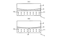
- FIG. 2 shows the state in the vicinity of the sliding interface of the sliding member 1 sliding with the mating member 2
- A shows a fluid lubrication state in which the lubricating oil 3 intervenes in the sliding interface
- FIG. 6 is a side sectional view showing a schematic configuration of boundary lubrication state in which local solid contact has occurred.
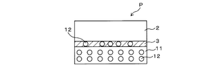
- FIG. 3 is a partially enlarged view of a portion (indicated by a point P) where the local solid contact has occurred in FIG. 2 (B).
- the lubricating oil 3 is interposed between the members 1 and 2, and the carbon-based molecules 12 present in the lubricating film 11 cause the sliding member 1 to slide. Does not contribute.
- the boundary lubrication state shown in FIG. 2 (B) is brought about by the application of high surface pressure between the members 1 and 2, local solid contact occurs at the sliding interface and the sliding surface of the sliding member There is microscopic wear.
- carbon-based molecules 12 having a rollable hollow structure are contained as a single substance or an aggregate of the single substance. Therefore, the carbon-based molecules 12 are exposed from the lubricating film 11 by the microscopic abrasion, and part of the carbon-based molecules 12 are supplied therefrom to the sliding interface. Since such carbon-based molecules 12 have a rollable hollow structure, they act as molecular level ball bearings at the sliding interface, as shown in FIG. In this case, when at least one carbon-based molecule 12 is present, local friction can be reduced compared to when it is not present. In particular, in this case, since the carbon-based molecule 12 can move in the lubricating oil 3, it can enter a necessary place, whereby the reduction effect can be effectively obtained.
- the friction can be significantly reduced at the sliding interface, the energy loss due to the friction can be reduced.
- Fuel consumption of an internal combustion engine such as an engine can be improved.
- the above effect can be obtained by the simple configuration in which the lubricating film 11 of the sliding member 1 contains the carbon-based molecule 12 having a hollow structure capable of rolling, mass production becomes possible, and the manufacturing cost Can be reduced.
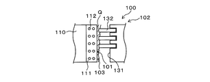
- FIG. 4 is a view showing a part of a schematic configuration of an internal combustion engine 100 (for example, an engine) using a cylinder bore 101 as a specific application example of the sliding member 1.
- FIG. 5 is a partially enlarged view of a point (indicated by point Q) at which local solid contact has occurred in internal combustion engine 100.
- the piston 102 slides along the inner circumferential surface (sliding surface) inside the cylinder bore 101.
- the piston 102 has a skirt portion (not shown) formed at the lower portion, a land portion 131 formed at the upper portion, and a ring portion 132 provided in a groove between the lands 131.
- the cylinder bore 101 corresponds to the sliding member 1
- a part of the cylinder block 110 corresponds to the main body 10
- the piston ring 132 corresponds to the mating member.
- a lubricating film 111 is formed on the inner peripheral surface of the cylinder bore 101, and carbon-based molecules 112 having a rollable structure are dispersedly contained in the lubricating film 111.
- the lubricant film 111 and the carbon-based molecule 112 correspond to the lubricant film 11 and the carbon-based molecule 12 and have the same configuration as them.
- the diameter d of the carbon-based molecule 112 (for example, the diameter of a spherical shape such as fullerene, for example, the diameter of the circular bottom of a cylindrical shape such as a nanotube) has a lubricating oil
- the aspect set smaller than the minimum oil film thickness t of 103 is preferable from the viewpoint of air tightness.
- the piston 102 rotates when sliding in the vertical direction with respect to the cylinder bore 101, in the embodiment using the carbon nanotube, the orientation direction of the carbon nanotube is aligned in the sliding direction according to the sliding.
Landscapes
- Chemical & Material Sciences (AREA)
- Engineering & Computer Science (AREA)
- Organic Chemistry (AREA)
- General Engineering & Computer Science (AREA)
- Mechanical Engineering (AREA)
- Chemical Kinetics & Catalysis (AREA)
- Materials Engineering (AREA)
- General Chemical & Material Sciences (AREA)
- Inorganic Chemistry (AREA)
- Metallurgy (AREA)
- Ceramic Engineering (AREA)
- Oil, Petroleum & Natural Gas (AREA)
- Lubricants (AREA)
- Physical Vapour Deposition (AREA)
- Carbon And Carbon Compounds (AREA)
- Chemical Vapour Deposition (AREA)
Abstract
When a high areal pressure is applied to the interface between a member (1) and a member (2), a local solid contact takes place at the sliding interface to cause microscopic wear on the sliding surface of the sliding member. The sliding member (1) has a lubricating film (11), in which carbon-based molecules (12) are contained as separate molecules or as aggregates of the molecules. Due to the microscopic wear, carbon-based molecules (12) are exposed on the lubricating film (11), and part of the exposed carbon-based molecules are released therefrom and supplied to the sliding interface. Such carbon-based molecules (12) have a rollable hollow structure and hence function as a ball bearing of a molecular size at the sliding interface. The presence of at least one carbon-based molecule in this case can reduce the local friction as compared with the case where no carbon-based molecule is present. Consequently, not only a significant reduction in friction can be attained, but also mass-production is possible and a reduction in production cost can be attained.
Description
本発明は、相手部材と摺動する摺動面を有する摺動部材およびその製造方法に係り、特に、相手部材とのフリクションの低減のための摺動面の改良に関する。
The present invention relates to a sliding member having a sliding surface that slides on a mating member and a method of manufacturing the same, and more particularly to improvement of the sliding surface for reducing friction with the mating member.
摺動部材の分野では、自動車のエンジン等のように相手部材との間に潤滑油が介在する環境下において、相手部材とのフリクションの低減化や耐摩耗性の向上が図られており、それらを実現するために、ボールベアリングが用いられることが多い。
In the field of sliding members, in an environment where lubricating oil intervenes with the other member, such as an automobile engine, etc., friction with the other member is reduced and wear resistance is improved. Ball bearings are often used to achieve this.
ところが、たとえばエンジン内部における多くの摺動部にボールベアリングを適用した場合、軽量化が困難となり、設置スペースが狭くなるため、ボールベアリングの使用の代わりに、PTFE〔テフロン(登録商標)〕や二硫化モリブデンからなる潤滑膜を摺動面に被覆している。このようにして固体潤滑特性の向上が図られることが多いが、その効果は、ボールベアリングの効果には及ばない。
However, for example, when a ball bearing is applied to many sliding parts inside the engine, it is difficult to reduce the weight and the installation space becomes narrow, so PTFE (Teflon (registered trademark)) or 2 is used instead of using a ball bearing. A sliding surface is coated with a lubricating film made of molybdenum sulfide. Thus, although the improvement of solid lubricating characteristics is often achieved, the effect does not reach the effect of the ball bearing.
以上のような背景から、摺動面でのフリクションの大幅な低減化のために、種々の技術が提案されている。たとえば特許文献1の技術は、ナノメータスケールの構造物への適用を目的として、2枚のグラファイト基板の互いの摺動面にフラーレンあるいはカーボンナノチューブを蒸着し、グラファイト基板の間に配置されたそれら分子を、分子ベアリングとして作用させることを提案している。
From the above background, various techniques have been proposed to significantly reduce friction on the sliding surface. For example, in the technology of Patent Document 1, fullerenes or carbon nanotubes are deposited on the sliding surfaces of two graphite substrates for application to a nanometer scale structure, and those molecules disposed between the graphite substrates are deposited. Is proposed to act as a molecular bearing.
しかしながら、この技術では、フリクションのゼロ化という高効果が期待されるものの、2枚のグラファイトの摺動面にフラーレンやカーボンナノチューブを、蒸着法により正確に配置する必要がある。このため、その製造が難しく、量産化への適用が非常に困難であり、しかも、その製造コストは、自動車部品に見合ったものではない。
However, in this technology, although a high effect of zeroing the friction is expected, it is necessary to accurately arrange fullerenes and carbon nanotubes on the sliding surfaces of two sheets of graphite by a vapor deposition method. Therefore, its production is difficult, its application to mass production is very difficult, and its production cost is not suitable for automobile parts.
したがって、本発明は、大幅な低フリクション化を図ることができるのはもちろんのこと、量産化を可能とするとともに、製造コストを低減することができる摺動部材およびその製造方法を提供することを目的とする。
Therefore, it is possible to provide a sliding member that can be mass-produced as well as being capable of mass production, as well as being capable of significantly reducing friction, and a method of manufacturing the same. To aim.
本発明の摺動部材は、相手部材と摺動する摺動面に潤滑膜が形成され、潤滑膜には、転動可能な中空構造を有する炭素系分子が、単体あるいはその単体の集合体として含有されていることを特徴としている。
In the sliding member of the present invention, a lubricating film is formed on the sliding surface that slides with the other member, and the carbon-based molecule having a hollow structure capable of rolling is formed on the lubricating film as a single substance or a group of single substances It is characterized by being contained.
本発明の摺動部材では、部材間への高面圧の印加により局所的固体接触が摺動界面で起こったとき、摺動部材の摺動面で微視的摩耗が生じる。ここで、摺動部材の摺動面に形成された潤滑膜には、転動可能な中空構造を有する炭素系分子が、単体あるいはその単体の集合体として含有されている。したがって、炭素系分子は、上記微視的摩耗によって、潤滑膜から露出し、その一部がそこから遊離することにより、摺動界面に供給される。そのような炭素系分子は、転動可能な中空構造を有するから、摺動界面で分子レベルのボールベアリングとして作用する。
In the sliding member of the present invention, when local solid contact occurs at the sliding interface due to the application of high surface pressure between the members, microscopic abrasion occurs on the sliding surface of the sliding member. Here, in the lubricating film formed on the sliding surface of the sliding member, carbon-based molecules having a rollable hollow structure are contained as a single substance or an aggregate of the single substance. Therefore, carbon-based molecules are supplied to the sliding interface by being exposed from the lubricating film by the above-mentioned microscopic wear and part of which is released therefrom. Since such carbon-based molecules have a rollable hollow structure, they act as molecular level ball bearings at the sliding interface.
この場合、炭素系分子が少なくとも一つ存在すると、存在しない場合と比較して、局所的フリクションを低減することができるので、摺動界面で大幅な低フリクション化を図ることができる。その結果、フリクションによるエネルギ損失の低減を図ることができるので、摺動部材が適用される自動車のエンジン等の内燃機関の燃費改善を図ることができる。また、摺動部材の摺動面の潤滑膜に転動可能な中空構造を有する炭素系分子を含有させるという簡単な構成によって上記効果を得ることができるので、 量産化が可能となるとともに、製造コストを低減することができる。
In this case, when at least one carbon-based molecule is present, local friction can be reduced as compared with the case where no carbon-based molecule is present, so that significant reduction in friction can be achieved at the sliding interface. As a result, energy loss due to friction can be reduced, and fuel efficiency of an internal combustion engine such as an automobile engine to which the sliding member is applied can be improved. In addition, since the above-described effect can be obtained by the simple configuration in which the lubricating film on the sliding surface of the sliding member contains carbon-based molecules having a hollow structure that can be rolled, mass production becomes possible, and manufacturing becomes possible. Cost can be reduced.
本発明の摺動部材は種々の構成を用いることができる。たとえば、潤滑膜は、DLC膜であることが好適である。この態様では、DLCは、その材質自体のフリクションが低く、硬度が高く(耐磨耗性が良好)、化学的安定性が高く(耐食性が良好)、凝着性が弱い(耐焼付き性が良好)であるから、摺動特性が良好となる。しかも、DLCは無害な炭素と水素を主成分としてから環境調和性を満足することができ、原料(炭化水素ガスまたはグラファイト)の存在量が多くて安定的である。
The sliding member of the present invention can use various configurations. For example, the lubricating film is preferably a DLC film. In this embodiment, DLC has low friction of its material itself, high hardness (good wear resistance), high chemical stability (good corrosion resistance), weak adhesion (good seizure resistance) Since it is), the sliding characteristic becomes good. Moreover, since DLC is composed of harmless carbon and hydrogen as main components, it can satisfy environmental compatibility, and the amount of the raw material (hydrocarbon gas or graphite) is large and stable.
炭素系分子としては、フラーレン、カーボンナノチューブ、アダマンタン、フラーレンの水素化合物、カーボンナノチューブの水素化合物、および、アダマンタンの水素化合物の少なくとも1つを用いることができる。フラーレンとしては、C60フラーレンを用いることができる。
As the carbon-based molecule, at least one of fullerene, carbon nanotube, adamantane, a hydrogen compound of fullerene, a hydrogen compound of carbon nanotube, and a hydrogen compound of adamantane can be used. As the fullerene, C 60 fullerene can be used.
本発明の摺動部材を、たとえばエンジンに適用する場合、摺動部材としてシリンダボアあるいはピストンに用いることができる。摺動部材としてシリンダボアを用いる場合、相手部材はピストンであり、摺動部材としてピストンを用いる場合、相手部材はシリンダボアである。また、摺動部材だけでなく相手部材にも、本発明の潤滑膜を適用してもよい。
When the sliding member of the present invention is applied to, for example, an engine, it can be used as a sliding member in a cylinder bore or a piston. When a cylinder bore is used as the sliding member, the mating member is a piston, and when using a piston as the sliding member, the mating member is a cylinder bore. Further, the lubricating film of the present invention may be applied not only to the sliding member but also to the other member.
本発明の摺動部材の製造方法は、潤滑膜の原材料へのプラズマ処理によって、相手部材と摺動する摺動面に潤滑膜を形成する潤滑膜形成工程を含み、潤滑膜形成工程では、転動可能な中空構造を有する炭素系分子、および、炭素系分子を水素化したものの少なくとも一方を含有する炭素系分子ガスを、原材料のプラズマに導入し、炭素系分子ガスをイオン化し、潤滑膜の原材料の摺動面への堆積時、イオン化された炭素系分子ガスを潤滑膜中に取り込ませて分子化することを特徴としている。
The method of manufacturing a sliding member according to the present invention includes a lubricating film forming step of forming a lubricating film on a sliding surface sliding on a mating member by plasma treatment of a raw material of the lubricating film, and in the lubricating film forming step, A carbon-based molecule gas containing at least one of a carbon-based molecule having a movable hollow structure and a hydrogenated carbon-based molecule is introduced into the raw material plasma to ionize the carbon-based molecule gas, and At the time of deposition of the raw material on the sliding surface, it is characterized in that the ionized carbon-based molecular gas is taken into the lubricating film to be molecularized.
本発明の摺動部材の製造方法は、本発明の摺動部材と同様な効果を得ることができる。
The manufacturing method of the sliding member of the present invention can obtain the same effect as the sliding member of the present invention.
本発明の摺動部材あるいはその製造方法によれば、相手部材との微視的摩耗によって、転動可能な中空構造を有する炭素系分子が潤滑膜から摺動界面に供給され、そこで分子レベルのボールベアリングとして作用する。これにより、大幅な低フリクション化を図ることができるのはもちろんのこと、量産化が可能となるとともに、製造コストを低減することができる等の効果を得ることができる。
According to the sliding member of the present invention or the method of manufacturing the same, carbon-based molecules having a rollable hollow structure are supplied from the lubricating film to the sliding interface due to microscopic wear with the other member, and there Act as a ball bearing. As a result, not only can the mass reduction be achieved, but also effects such as reduction of manufacturing costs can be obtained.
1…摺動部材、2…相手部材、12,112…炭素系分子、101…シリンダボア(摺動部材)、102…ピストン(相手部材)、132…リング部(相手部材)
DESCRIPTION OF SYMBOLS 1 ... Sliding member, 2 ... Counterpart member, 12,112 ... Carbon-based molecule | numerator, 101 ... Cylinder bore (sliding member) 102 ... Piston (parting member), 132 ... Ring part (parting member)
(1)摺動部材の基本構成
以下、本発明の一実施形態について図面を参照して説明する。図1は、本発明に係る一実施形態の摺動部材1の概略構成を表す側断面図である。摺動部材1は本体部10を備え、本体部10の表面に潤滑膜11が形成されている。潤滑膜11の内部には、転動可能な中空構造を有する炭素系分子12が分散して含有されている。 (1) Basic Configuration of Sliding Member Hereinafter, an embodiment of the present invention will be described with reference to the drawings. FIG. 1 is a side sectional view showing a schematic configuration of a sliding member 1 according to an embodiment of the present invention. The sliding member 1 includes amain body 10, and a lubricating film 11 is formed on the surface of the main body 10. Inside the lubricating film 11, carbon-based molecules 12 having a rollable hollow structure are contained in a dispersed manner.
以下、本発明の一実施形態について図面を参照して説明する。図1は、本発明に係る一実施形態の摺動部材1の概略構成を表す側断面図である。摺動部材1は本体部10を備え、本体部10の表面に潤滑膜11が形成されている。潤滑膜11の内部には、転動可能な中空構造を有する炭素系分子12が分散して含有されている。 (1) Basic Configuration of Sliding Member Hereinafter, an embodiment of the present invention will be described with reference to the drawings. FIG. 1 is a side sectional view showing a schematic configuration of a sliding member 1 according to an embodiment of the present invention. The sliding member 1 includes a
潤滑膜11は、たとえばダイヤモンド・ライク・カーボン(Diamond-Like Carbon(DLC))からなるDLC膜であり、その膜厚はたとえば3μmである。潤滑膜11としては、DLC膜に限定されず、種々の変形が可能である。たとえば、CrNや、TiCN、TiAlN等からなるドライコーティング膜、あるいは、Ni等のめっき膜でもよい。
The lubricating film 11 is a DLC film made of, for example, Diamond-Like Carbon (DLC), and its film thickness is, for example, 3 μm. The lubricating film 11 is not limited to the DLC film, and various modifications are possible. For example, a dry coating film made of CrN, TiCN, TiAlN or the like, or a plating film of Ni or the like may be used.
DLCは、その材質自体のフリクションが低く、硬度が高く(耐磨耗性が良好)、化学的安定性が高く(耐食性が良好)、凝着性が弱い(耐焼付き性が良好)。しかも、DLCは無害な炭素と水素を主成分としてから環境調和性を満足することができ、原料(炭化水素ガスまたはグラファイト)の存在量が多くて安定的である。具体的には、上記他の材質と比較した場合、DLCは、同等の耐食性を有するCrNより、フリクションが低い。また、DLCは、上記いずれの特性においても、Niめっきより優れている。
DLC has low friction of the material itself, high hardness (good wear resistance), high chemical stability (good corrosion resistance) and weak adhesion (good seizure resistance). Moreover, since DLC is composed of harmless carbon and hydrogen as main components, it can satisfy environmental compatibility, and the amount of the raw material (hydrocarbon gas or graphite) is large and stable. Specifically, DLC has lower friction than CrN having the same corrosion resistance as compared to the other materials. In addition, DLC is superior to Ni plating in any of the above characteristics.
このようにDLCは、上記他の材質と比較して、潤滑膜として種々のメリットがあるから、好適である。また、炭素系分子12としてフラーレンを用いた場合、DLC膜の表面が摺動時のエネルギによりグラファイト化した際、DLC膜は、フラーレンとの接触点においてナノスケールのギア(ナノギア)として作用し、低フリクション化に寄与する。
As described above, DLC is preferable because it has various merits as a lubricating film as compared with the other materials described above. When fullerene is used as the carbon-based molecule 12, when the surface of the DLC film is graphitized by the energy at the time of sliding, the DLC film acts as a nanoscale gear (nanogear) at the contact point with the fullerene, Contribute to low friction.
炭素系分子12では、その一部が、潤滑膜11の相手部材(図示略)との局所的固体接触時に、潤滑膜11から摺動面へ遊離して、そこで分子ベアリングとして作用する。また、炭素系分子12は、図6(A)に示すように分子単体で存在していてもよく、あるいは、図6(B)に示すように、その分子が複数からなる集合体で存在していてもよい。なお、図6では、図示の便宜のため、炭素系分子12の分子を単純化して示している。
A part of the carbon-based molecule 12 is released from the lubricating film 11 to the sliding surface at the time of local solid contact with the partner member (not shown) of the lubricating film 11, and acts as a molecular bearing there. In addition, the carbon-based molecule 12 may be present as a single molecule as shown in FIG. 6 (A), or as shown in FIG. 6 (B), the carbon-based molecule 12 is present as an aggregate composed of plural molecules. It may be In FIG. 6, the molecule of the carbon-based molecule 12 is shown in a simplified manner for the convenience of illustration.
潤滑膜11中に含有される炭素系分子12としては、多数個の炭素原子によって合成される炭素の同素体で、外部からの荷重に対する転がり方向に異方性を持たない球形状分子分子(たとえばC60フラーレン)あるいはその水素化合物が最も望ましい。また、閉構造の擬似球形体(たとえばC70、C74、C76等の高次フラーレン、アダマンタン(Adamantane、C10H16)、あるいは、それらの水素化合物)でもよい。さらに、それらと比較してフリクション性能が劣るが、少なくとも一方向に円形断面を持つ分子(たとえばカーボンナノチューブ)あるいはその水素化合物でもよい。
The carbon-based molecule 12 contained in the lubricating film 11 is an allotrope of carbon synthesized by a large number of carbon atoms, and is a spherical molecule (eg, C-like molecule having no anisotropy in the rolling direction with respect to external load) 60 fullerene) or its hydrogen compound is most desirable. In addition, it may be a pseudo-spherical body having a closed structure (for example, higher fullerenes such as C 70 , C 74 and C 76 , adamantane (Adamantane, C 10 H 16 ), or a hydrogen compound thereof). Furthermore, although they have inferior friction performance as compared with them, they may be molecules (for example, carbon nanotubes) having a circular cross section in at least one direction or hydrogen compounds thereof.
具体的には、C60フラーレンは、直径0.7nm程度の球状をなし、高硬度を有するから、その球形状は、高荷重条件下でも維持される。また、炭素系分子12の上記遊離は、潤滑膜11表面における極一部によるものであるから、潤滑膜11と相手部材との間の潤滑油中への堆積が防止されるとともに、装置内のフィルタを潤滑油が通過する時、炭素系分子12によるその目詰まりが防止される。
Specifically, C 60 fullerene is spherical with a diameter of about 0.7 nm and has high hardness, so the spherical shape is maintained even under high load conditions. Further, since the liberation of the carbon-based molecule 12 is due to a part of the surface of the lubricating film 11, the deposition in the lubricating oil between the lubricating film 11 and the other member is prevented, and As the lubricating oil passes through the filter, its clogging by the carbon-based molecules 12 is prevented.
炭素系分子12は、転動容易性の観点から、上記のようにC60フラーレンのように球形状をなすのが望ましいが、C70フラーレン等の高次フラーレンや、カーボンナノチューブ、アダマンタン(Adamantane)等を用いる場合、転動動作を起こし(転動可能性を有すること)、かつ転動方向の直径が数nm以下と非常に小さいものであればよい。それら材質を用いる場合、転動方向の直径が上記値よりも大きくなると、転動動作が困難となる。アダマンタンを用いる場合、アダマンタンはフラーレンよりも小さいから、フラーレンが入り込むことが困難な摺動界面のクリアランスにも入り込むことができ、これにより摺動特性が良好となる。
The carbon-based molecule 12 preferably has a spherical shape like C 60 fullerene as described above from the viewpoint of ease of rolling, but higher-order fullerenes such as C 70 fullerene, carbon nanotubes, adamantane (Adamantane) In the case of using or the like, it is sufficient if the rolling operation is caused (having the rollability) and the diameter in the rolling direction is as small as several nm or less. In the case of using these materials, when the diameter in the rolling direction is larger than the above value, the rolling operation becomes difficult. In the case of using adamantane, since adamantane is smaller than fullerene, it can enter into the clearance of the sliding interface where it is difficult for fullerenes to enter, whereby the sliding characteristics are improved.
炭素系分子12が球形状をなさない場合(たとえば、カーボンナノチューブのように円柱状をなす場合)、潤滑膜11の表面(摺動面)からの遊離時にカーボンナノチューブが摺動方向に転動し易いことが望ましい。これを実現するために、潤滑膜11の形成時にカーボンナノチューブを予め配向させておくことが好適である。
When the carbon-based molecules 12 do not form a spherical shape (for example, when forming a cylindrical shape like a carbon nanotube), the carbon nanotube rolls in the sliding direction when released from the surface (sliding surface) of the lubricating film 11 It is desirable to be easy. In order to realize this, it is preferable to orient carbon nanotubes in advance when the lubricating film 11 is formed.
炭素系分子12は、以上のような構成とする場合、転動可能性およびナノスケールのサイズを有することが、分子ベアリングとしての機能を発揮するために重要である。
When configured as described above, it is important for the carbon-based molecule 12 to have rollability and a nanoscale size in order to function as a molecular bearing.
(2)摺動部材の製造方法
本発明の一実施形態に係る摺動部材1の製造方法について説明する。摺動部材1の製造方法では、プラズマ処理によって、潤滑膜11の原材料からなる原材料へのプラズマ処理によって、本体部10の表面(摺動面)に潤滑膜11を形成する(潤滑膜形成工程)。 (2) Method of Manufacturing Sliding Member A method of manufacturing the sliding member 1 according to an embodiment of the present invention will be described. In the method of manufacturing the sliding member 1, the lubricatingfilm 11 is formed on the surface (sliding surface) of the main body 10 by plasma processing to a raw material consisting of the raw material of the lubricating film 11 (lubricating film forming step) .
本発明の一実施形態に係る摺動部材1の製造方法について説明する。摺動部材1の製造方法では、プラズマ処理によって、潤滑膜11の原材料からなる原材料へのプラズマ処理によって、本体部10の表面(摺動面)に潤滑膜11を形成する(潤滑膜形成工程)。 (2) Method of Manufacturing Sliding Member A method of manufacturing the sliding member 1 according to an embodiment of the present invention will be described. In the method of manufacturing the sliding member 1, the lubricating
このような潤滑膜形成工程では、炭素系分子、および、炭素系分子を水素化したものの少なくとも一方を含有する炭素系分子ガスを原材料のプラズマに導入すると、炭素系分子ガスは、脱水素化されてイオン化する。原材料のプラズマが本体部10の表面に衝突することより、そこに堆積して潤滑膜11が形成される。このとき、イオン化された炭素系分子ガスも本体部10の表面に衝突することより、潤滑膜11に取り込まれて、その内部で炭素を受け取って分子化する。
In such a lubricating film forming step, when a carbon-based molecule gas containing at least one of a carbon-based molecule and a hydrogenated carbon-based molecule is introduced into the plasma of the raw material, the carbon-based molecule gas is dehydrogenated Ionize. As the raw material plasma collides with the surface of the main body 10, it is deposited there to form the lubricating film 11. At this time, since the ionized carbon-based molecular gas also collides with the surface of the main body 10, it is taken into the lubricating film 11, and carbon is received therein to be molecularized.
なお、この場合、電圧が印加された本体部10への高速衝突では、イオン化された炭素系分子は、衝突によって急激にエネルギを失う。このとき、イオン化された炭素系分子および水素イオンは安定化しようとすることから、イオン化された炭素系分子は、水素イオンを受け取り、その結果、炭素系分子中で水素化フラーレンとして存在するものもある。
In this case, in the high-speed collision to the main body 10 to which the voltage is applied, the ionized carbon-based molecule rapidly loses energy by the collision. At this time, since the ionized carbon-based molecules and hydrogen ions are to be stabilized, the ionized carbon-based molecules receive hydrogen ions, and as a result, some of the carbon-based molecules exist as hydrogenated fullerenes. is there.
以上のようにして、摺動部材1の本体部10の表面に、潤滑膜11が形成され、潤滑膜11内部には炭素系分子12が分散した状態となる。このようなプラズマ処理を用いた潤滑膜形成工程の具体的手法として、次のようなCVD法あるいはPVD法がある。
As described above, the lubricating film 11 is formed on the surface of the main body 10 of the sliding member 1, and the carbon-based molecules 12 are dispersed in the lubricating film 11. As a specific method of the lubricating film formation step using such plasma processing, there are the following CVD method or PVD method.
CVD法を用いる場合について説明する。まず、CVD装置の真空炉内に摺動部材1の本体部10をセットする。次いで、真空炉の真空度をたとえば10-2~10-3Pa程度に、温度をたとえば50~150℃程度に調整した後、本体部10にDCパルス電圧を負荷する。
The case of using the CVD method will be described. First, the main body 10 of the sliding member 1 is set in the vacuum furnace of the CVD apparatus. Next, after adjusting the degree of vacuum of the vacuum furnace to, for example, about 10 −2 to 10 −3 Pa and the temperature to, for example, about 50 to 150 ° C., DC pulse voltage is applied to the main body 10.
続いて、還元性ガス(たとえばアルゴンガス)を導入し、プラズマ化すると、イオンボンバードメント効果により本体部10の表面の清浄性が向上する。次いで、潤滑膜11の原料ガス(DLC膜形成の場合、炭化水素ガス(たとえばブタンやアセチレン等)、および、一部が水素化された炭素分子ボール(たとえばフラーレン)を真空炉内に導入する。
Subsequently, when a reducing gas (for example, argon gas) is introduced and turned into plasma, the cleanliness of the surface of the main body 10 is improved by the ion bombardment effect. Next, a raw material gas of the lubricating film 11 (in the case of DLC film formation, a hydrocarbon gas (for example, butane, acetylene or the like) and a carbon molecule ball partially hydrogenated (for example, fullerene) are introduced into a vacuum furnace.
この場合、ガス流入量、圧力、温度、バイアスの電圧値、パルスDuty値(矩形波の1周期とHighパルス側の幅の比率)は、最適なプラズマ状態を継続できる範囲に常時調整される。これにより、本体部10の表面上に潤滑膜11が形成され、潤滑膜11内部には炭素系分子12が分散した状態となる。
In this case, the amount of gas inflow, pressure, temperature, voltage value of bias, pulse duty value (ratio of one cycle of rectangular wave to the width of high pulse side) are always adjusted within a range where the optimum plasma state can be continued. As a result, the lubricating film 11 is formed on the surface of the main body 10, and the carbon-based molecules 12 are dispersed in the lubricating film 11.
PVD法を用いる場合について説明する。まず、PVD装置の真空炉内に摺動部材1の本体部10をセットする。次いで、真空炉内の真空度をたとえば10-2~10-3Pa程度、温度をたとえば50~150℃程度に調整した後、本体部10にDCパルス電圧を負荷する。
The case of using the PVD method will be described. First, the main body 10 of the sliding member 1 is set in the vacuum furnace of the PVD apparatus. Next, after adjusting the degree of vacuum in the vacuum furnace to, for example, about 10 −2 to 10 −3 Pa and the temperature to, for example, about 50 to 150 ° C., a DC pulse voltage is applied to the main body 10.
続いて、真空炉内に還元性ガス(たとえばアルゴンガス)を導入し、それをプラズマ化すると、イオンボンバードメント効果により本体部10の表面の清浄性が向上する。次に、真空炉内に設置された潤滑膜11の固体材料(たとえばグラファイト)をアーク放電や電子線照射等の手法によりプラズマ化すると同時に、一部が水素化された炭素系分子(たとえばフラーレン)を導入してプラズマ化する。すると、本体部10の表面上に潤滑膜11が形成され、潤滑膜11内部には炭素系分子12が分散した状態となる。
Subsequently, when a reducing gas (for example, argon gas) is introduced into the vacuum furnace and it is plasmatized, the cleanliness of the surface of the main body 10 is improved by the ion bombardment effect. Next, a solid material (for example, graphite) of the lubricating film 11 placed in a vacuum furnace is plasmatized by a method such as arc discharge or electron beam irradiation, and at the same time a carbon-based molecule (for example, fullerene) partially hydrogenated To make it plasma. Then, the lubricating film 11 is formed on the surface of the main body 10, and the carbon-based molecules 12 are dispersed in the lubricating film 11.
(3)摺動部材の動作
摺動部材1の動作について、図2,3を参照して説明する。図2は、相手部材2と摺動する摺動部材1の摺動界面近傍の状態を表し、(A)は摺動界面に潤滑油3が介在する流体潤滑状態、(B)は摺動界面で局所的固体接触が起こった境界潤滑状態の概略構成を表す側断面図である。図3は、図2(B)で局所的固体接触が起こった箇所(点Pで示される箇所)の部分拡大図である。 (3) Operation of Sliding Member The operation of the sliding member 1 will be described with reference to FIGS. FIG. 2 shows the state in the vicinity of the sliding interface of the sliding member 1 sliding with themating member 2, (A) shows a fluid lubrication state in which the lubricating oil 3 intervenes in the sliding interface, (B) shows the sliding interface FIG. 6 is a side sectional view showing a schematic configuration of boundary lubrication state in which local solid contact has occurred. FIG. 3 is a partially enlarged view of a portion (indicated by a point P) where the local solid contact has occurred in FIG. 2 (B).
摺動部材1の動作について、図2,3を参照して説明する。図2は、相手部材2と摺動する摺動部材1の摺動界面近傍の状態を表し、(A)は摺動界面に潤滑油3が介在する流体潤滑状態、(B)は摺動界面で局所的固体接触が起こった境界潤滑状態の概略構成を表す側断面図である。図3は、図2(B)で局所的固体接触が起こった箇所(点Pで示される箇所)の部分拡大図である。 (3) Operation of Sliding Member The operation of the sliding member 1 will be described with reference to FIGS. FIG. 2 shows the state in the vicinity of the sliding interface of the sliding member 1 sliding with the
図2(A)に示す流体潤滑状態では、部材1,2間に潤滑油3が介在しており、潤滑膜11中に存在している炭素系分子12は、摺動部材1の摺動には寄与しない。一方、部材1,2間への高面圧の印加によって、図2(B)に示す境界潤滑状態となったとき、局所的固体接触が摺動界面で起こり、摺動部材の摺動面で微視的摩耗が生じる。
In the fluid lubrication state shown in FIG. 2A, the lubricating oil 3 is interposed between the members 1 and 2, and the carbon-based molecules 12 present in the lubricating film 11 cause the sliding member 1 to slide. Does not contribute. On the other hand, when the boundary lubrication state shown in FIG. 2 (B) is brought about by the application of high surface pressure between the members 1 and 2, local solid contact occurs at the sliding interface and the sliding surface of the sliding member There is microscopic wear.
ここで、摺動部材1の潤滑膜11には、転動可能な中空構造を有する炭素系分子12が、単体あるいはその単体の集合体として含有されている。したがって、上記微視的摩耗によって、炭素系分子12が潤滑膜11から露出し、その一部がそこから遊離することにより、摺動界面に供給される。そのような炭素系分子12は、転動可能な中空構造を有するから、図3に示すように、摺動界面で分子レベルのボールベアリングとして作用する。この場合、炭素系分子12が少なくとも一つ存在すると、存在しない場合と比較して、局所的フリクションを低減することができる。特に、この場合、炭素系分子12は、潤滑油3の中を移動することができるから、必要な箇所に入り込むことができ、これにより、その低減効果を効果的に得ることができる。
Here, in the lubricating film 11 of the sliding member 1, carbon-based molecules 12 having a rollable hollow structure are contained as a single substance or an aggregate of the single substance. Therefore, the carbon-based molecules 12 are exposed from the lubricating film 11 by the microscopic abrasion, and part of the carbon-based molecules 12 are supplied therefrom to the sliding interface. Since such carbon-based molecules 12 have a rollable hollow structure, they act as molecular level ball bearings at the sliding interface, as shown in FIG. In this case, when at least one carbon-based molecule 12 is present, local friction can be reduced compared to when it is not present. In particular, in this case, since the carbon-based molecule 12 can move in the lubricating oil 3, it can enter a necessary place, whereby the reduction effect can be effectively obtained.
以上のことから本実施形態では、摺動界面で大幅な低フリクション化を図ることができるので、フリクションによるエネルギ損失の低減を図ることができ、その結果、摺動部材1が適用される自動車のエンジン等の内燃機関の燃費改善を図ることができる。また、摺動部材1の潤滑膜11に転動可能な中空構造を有する炭素系分子12を含有させるという簡単な構成によって上記効果を得ることができるので、 量産化が可能となるとともに、製造コストを低減することができる。
From the above, in the present embodiment, since the friction can be significantly reduced at the sliding interface, the energy loss due to the friction can be reduced. As a result, in the automobile to which the sliding member 1 is applied Fuel consumption of an internal combustion engine such as an engine can be improved. In addition, since the above effect can be obtained by the simple configuration in which the lubricating film 11 of the sliding member 1 contains the carbon-based molecule 12 having a hollow structure capable of rolling, mass production becomes possible, and the manufacturing cost Can be reduced.
(4)摺動部材の適用例
摺動部材の具体的な適用例について図4,5を参照して説明する。図4は、摺動部材1の具体的な適用例としてのシリンダボア101を用いた内燃機関100(たとえばエンジン)の概略構成の一部を表す図である。図5は、内燃機関100において局所的固体接触が起こった箇所(点Qで示される箇所)の部分拡大図である。内燃機関100では、ピストン102がシリンダボア101の内部において、その内周面(摺動面)に沿って摺動する。ピストン102は、下部に形成されたスカート部(図示略)、上部に形成されたランド部131、および、ランド131部間の溝に設けられたリング部132を有する。 (4) Application Example of Sliding Member A specific application example of the sliding member will be described with reference to FIGS. FIG. 4 is a view showing a part of a schematic configuration of an internal combustion engine 100 (for example, an engine) using acylinder bore 101 as a specific application example of the sliding member 1. FIG. 5 is a partially enlarged view of a point (indicated by point Q) at which local solid contact has occurred in internal combustion engine 100. As shown in FIG. In the internal combustion engine 100, the piston 102 slides along the inner circumferential surface (sliding surface) inside the cylinder bore 101. The piston 102 has a skirt portion (not shown) formed at the lower portion, a land portion 131 formed at the upper portion, and a ring portion 132 provided in a groove between the lands 131.
摺動部材の具体的な適用例について図4,5を参照して説明する。図4は、摺動部材1の具体的な適用例としてのシリンダボア101を用いた内燃機関100(たとえばエンジン)の概略構成の一部を表す図である。図5は、内燃機関100において局所的固体接触が起こった箇所(点Qで示される箇所)の部分拡大図である。内燃機関100では、ピストン102がシリンダボア101の内部において、その内周面(摺動面)に沿って摺動する。ピストン102は、下部に形成されたスカート部(図示略)、上部に形成されたランド部131、および、ランド131部間の溝に設けられたリング部132を有する。 (4) Application Example of Sliding Member A specific application example of the sliding member will be described with reference to FIGS. FIG. 4 is a view showing a part of a schematic configuration of an internal combustion engine 100 (for example, an engine) using a
シリンダボア101が摺動部材1に対応し、シリンダブロック110の一部が本体部10に対応し、ピストンリング132が相手部材に対応している。シリンダボア101の内周面には、潤滑膜111が形成され、潤滑膜111の内部に転動可能な構造を有する炭素系分子112が分散して含有されている。潤滑膜111および炭素系分子112は、潤滑膜11および炭素系分子12に対応し、それらと同様な構成を有している。
The cylinder bore 101 corresponds to the sliding member 1, a part of the cylinder block 110 corresponds to the main body 10, and the piston ring 132 corresponds to the mating member. A lubricating film 111 is formed on the inner peripheral surface of the cylinder bore 101, and carbon-based molecules 112 having a rollable structure are dispersedly contained in the lubricating film 111. The lubricant film 111 and the carbon-based molecule 112 correspond to the lubricant film 11 and the carbon-based molecule 12 and have the same configuration as them.
このような内燃機関100では、次のような態様を用いると、摺動部材1による上記効果を効果的に得ることができる。たとえば、図5に示すように、炭素系分子112の直径d(たとえばフラーレンのように球形状の場合はその直径、たとえばナノチューブのように円柱状の場合は円形状底面の直径)が、潤滑油103の最小油膜厚tよりも小さく設定する態様は、気密性の観点から好適である。また、ピストン102は、シリンダボア101に対する上下方向への摺動時に回転するから、カーボンナノチューブを用いる態様では、その摺動に従ってカーボンナノチューブの配向方向が摺動方向に揃ってくる。
In the internal combustion engine 100 as described above, the above-described effect of the sliding member 1 can be effectively obtained by using the following aspect. For example, as shown in FIG. 5, the diameter d of the carbon-based molecule 112 (for example, the diameter of a spherical shape such as fullerene, for example, the diameter of the circular bottom of a cylindrical shape such as a nanotube) has a lubricating oil The aspect set smaller than the minimum oil film thickness t of 103 is preferable from the viewpoint of air tightness. Further, since the piston 102 rotates when sliding in the vertical direction with respect to the cylinder bore 101, in the embodiment using the carbon nanotube, the orientation direction of the carbon nanotube is aligned in the sliding direction according to the sliding.
Claims (8)
- 相手部材と摺動する摺動面に潤滑膜が形成され、
前記潤滑膜には、転動可能な中空構造を有する炭素系分子が、単体あるいはその単体の集合体として含有されていることを特徴とする摺動部材。 A lubricating film is formed on the sliding surface that slides with the mating member,
A sliding member characterized in that the lubricating film contains carbon-based molecules having a rollable hollow structure as a single substance or an aggregate of the single substance. - 前記潤滑膜は、DLC膜であることを特徴とする請求項1に記載の摺動部材。 The sliding member according to claim 1, wherein the lubricating film is a DLC film.
- 前記炭素系分子は、フラーレン、カーボンナノチューブ、アダマンタン、フラーレンの水素化合物、カーボンナノチューブの水素化合物、および、アダマンタンの水素化合物の少なくとも1つであることを特徴とする請求項1または2に記載の摺動部材。 The slide according to claim 1 or 2, wherein the carbon-based molecule is at least one of fullerene, carbon nanotube, adamantane, a hydrogen compound of fullerene, a hydrogen compound of carbon nanotube, and a hydrogen compound of adamantane. Moving member.
- 前記フラーレンは、C60フラーレンであることを特徴とする請求項1~3のいずれかに記載の摺動部材。 The sliding member according to any one of claims 1 to 3, wherein the fullerene is a C 60 fullerene.
- 潤滑膜の原材料へのプラズマ処理によって、相手部材と摺動する摺動面に前記潤滑膜を形成する潤滑膜形成工程を含み、
前記潤滑膜形成工程では、
転動可能な中空構造を有する炭素系分子、および、前記炭素系分子を水素化したものの少なくとも一方を含有する炭素系分子ガスを、前記原材料のプラズマに導入し、
前記炭素系分子ガスをイオン化し、
前記潤滑膜の原材料の前記摺動面への堆積時、前記イオン化された炭素系分子ガスを前記潤滑膜中に取り込ませて分子化することを特徴とする摺動部材の製造方法。 Including a lubricating film forming step of forming the lubricating film on a sliding surface which slides on a mating member by plasma treatment of a raw material of the lubricating film,
In the lubricating film forming step,
Introducing a carbon-based molecule gas containing at least one of a carbon-based molecule having a rollable hollow structure and a hydrogenated one of the carbon-based molecules into the plasma of the raw material;
Ionize the carbon-based molecular gas,
A method of manufacturing a sliding member, wherein the ionized carbon-based molecular gas is taken into the lubricating film to be molecularized when the raw material of the lubricating film is deposited on the sliding surface. - 前記潤滑膜は、DLC膜であることを特徴とする請求項5に記載の摺動部材の製造方法。 The method according to claim 5, wherein the lubricating film is a DLC film.
- 前記炭素系分子は、フラーレン、カーボンナノチューブ、アダマンタン、フラーレンの水素化合物、カーボンナノチューブの水素化合物、および、アダマンタンの水素化合物の少なくとも1つであることを特徴とする請求項5または6に記載の摺動部材の製造方法。 The slide according to claim 5 or 6, wherein the carbon-based molecule is at least one of fullerene, carbon nanotube, adamantane, a hydrogen compound of fullerene, a hydrogen compound of carbon nanotube, and a hydrogen compound of adamantane. Method of manufacturing moving member.
- 前記フラーレンは、C60フラーレンであることを特徴とする請求項5~7のいずれかに記載の摺動部材の製造方法。 The method for producing a sliding member according to any one of claims 5 to 7, wherein the fullerene is a C 60 fullerene.
Priority Applications (2)
| Application Number | Priority Date | Filing Date | Title |
|---|---|---|---|
| EP09827311A EP2361881A4 (en) | 2008-11-19 | 2009-11-06 | Sliding member and process for producing same |
| US13/127,689 US20110249920A1 (en) | 2008-11-19 | 2009-11-06 | Sliding member and process for producing the same |
Applications Claiming Priority (2)
| Application Number | Priority Date | Filing Date | Title |
|---|---|---|---|
| JP2008295399A JP2010120806A (en) | 2008-11-19 | 2008-11-19 | Sliding member and method of manufacturing the same |
| JP2008-295399 | 2008-11-19 |
Publications (1)
| Publication Number | Publication Date |
|---|---|
| WO2010058530A1 true WO2010058530A1 (en) | 2010-05-27 |
Family
ID=42197973
Family Applications (1)
| Application Number | Title | Priority Date | Filing Date |
|---|---|---|---|
| PCT/JP2009/005896 WO2010058530A1 (en) | 2008-11-19 | 2009-11-06 | Sliding member and process for producing same |
Country Status (4)
| Country | Link |
|---|---|
| US (1) | US20110249920A1 (en) |
| EP (1) | EP2361881A4 (en) |
| JP (1) | JP2010120806A (en) |
| WO (1) | WO2010058530A1 (en) |
Cited By (4)
| Publication number | Priority date | Publication date | Assignee | Title |
|---|---|---|---|---|
| CN103982548A (en) * | 2014-05-19 | 2014-08-13 | 金迪荣 | Bimetallic balance bearing |
| CN104061231A (en) * | 2014-05-18 | 2014-09-24 | 金迪荣 | Double-metal balancing bearing of automobile |
| US9926968B2 (en) * | 2013-08-21 | 2018-03-27 | Mag Ias Gmbh | Sliding surface |
| CN112940824A (en) * | 2021-02-06 | 2021-06-11 | 中国科学院兰州化学物理研究所 | Application and preparation method of lubricating oil additive, high-temperature lubricating oil, preparation method and application |
Families Citing this family (8)
| Publication number | Priority date | Publication date | Assignee | Title |
|---|---|---|---|---|
| JP5669042B2 (en) * | 2011-02-10 | 2015-02-12 | 勝義 近藤 | Sliding member and manufacturing method thereof |
| FR2985739B1 (en) * | 2012-01-12 | 2014-02-28 | Centre Nat Rech Scient | STRENGTHENING THE ADHESION OR FIXATION OF CARBON NANOTUBES TO THE SURFACE OF A MATERIAL BY A CARBON LAYER |
| DE102013202121A1 (en) * | 2013-02-08 | 2014-08-14 | Ks Gleitlager Gmbh | Metal / plastic sliding bearing composite material and slide bearing element produced therefrom |
| GB2513867A (en) * | 2013-05-07 | 2014-11-12 | Mahle Int Gmbh | Sliding engine component |
| CN103982549A (en) * | 2014-05-19 | 2014-08-13 | 金迪荣 | Multilayered composite wear-resistant balance bearing |
| CN103982546A (en) * | 2014-05-20 | 2014-08-13 | 金迪荣 | Multilayer wear-resistant automobile balance bearing |
| CN113151785B (en) * | 2020-01-22 | 2022-02-08 | 中国工程物理研究院激光聚变研究中心 | Film preparation assembly, film preparation method and application thereof |
| WO2023063286A1 (en) * | 2021-10-13 | 2023-04-20 | 株式会社レゾナック | Structure, sliding member, and methods for manufacturing these |
Citations (2)
| Publication number | Priority date | Publication date | Assignee | Title |
|---|---|---|---|---|
| JP2001261318A (en) * | 2000-03-23 | 2001-09-26 | Kobe Steel Ltd | Diamond-like carbon hard multi-layered film and member excellent in wear resistance and excellent sliding characteristic |
| JP2003062799A (en) | 2001-08-27 | 2003-03-05 | Japan Science & Technology Corp | Lubrication system using carbon ball molecule or carbon tube molecule |
Family Cites Families (8)
| Publication number | Priority date | Publication date | Assignee | Title |
|---|---|---|---|---|
| US5374463A (en) * | 1991-10-22 | 1994-12-20 | International Business Machines Corporation | Magnetic recording disk having a contiguous fullerene film and a protective overcoat |
| US7132936B1 (en) * | 1999-04-20 | 2006-11-07 | Peter Norton | Angular rate sensor |
| JP5168744B2 (en) * | 2000-07-31 | 2013-03-27 | オイレス工業株式会社 | Lubricating coating composition and sliding member coated with the composition |
| DE10254368B3 (en) * | 2002-11-21 | 2004-06-17 | Daimlerchrysler Ag | Lubricating sliding system consists of a smooth and hard base member and an opposing member with an elastic friction surface |
| EP1735376B1 (en) * | 2004-04-15 | 2017-01-11 | Showa Denko K.K. | Method of producing a conductive resin composition |
| US20070249507A1 (en) * | 2006-04-24 | 2007-10-25 | Nissan Motor Co., Ltd. | Hard carbon film and hard carbon film sliding member |
| JP2009133408A (en) * | 2007-11-30 | 2009-06-18 | Nsk Ltd | Rolling slide member, and rolling device and pulley device using this member |
| JP2009167512A (en) * | 2008-01-21 | 2009-07-30 | Kobe Steel Ltd | Diamond-like carbon film for sliding component and method for manufacturing the same |
-
2008
- 2008-11-19 JP JP2008295399A patent/JP2010120806A/en active Pending
-
2009
- 2009-11-06 EP EP09827311A patent/EP2361881A4/en not_active Withdrawn
- 2009-11-06 US US13/127,689 patent/US20110249920A1/en not_active Abandoned
- 2009-11-06 WO PCT/JP2009/005896 patent/WO2010058530A1/en active Application Filing
Patent Citations (2)
| Publication number | Priority date | Publication date | Assignee | Title |
|---|---|---|---|---|
| JP2001261318A (en) * | 2000-03-23 | 2001-09-26 | Kobe Steel Ltd | Diamond-like carbon hard multi-layered film and member excellent in wear resistance and excellent sliding characteristic |
| JP2003062799A (en) | 2001-08-27 | 2003-03-05 | Japan Science & Technology Corp | Lubrication system using carbon ball molecule or carbon tube molecule |
Non-Patent Citations (3)
| Title |
|---|
| MASATO BAN: "Nano Kozoka ni yoru DLC-maku no Taikyusei Kojo", THE JOURNAL OF THE SURFACE FINISHING SOCIETY OF JAPAN, vol. 58, no. 1, 1 January 2007 (2007-01-01), pages 23 - 27, XP008164380 * |
| S. SHIMIZU ET AL.: "Development of nanoparticle dispersive diamond- like carbon film", SYNOPSES OF THE INTERNATIONAL TRIBOLOGY CONFERENCE KOBE, 2 June 2005 (2005-06-02), pages 379 * |
| See also references of EP2361881A4 |
Cited By (4)
| Publication number | Priority date | Publication date | Assignee | Title |
|---|---|---|---|---|
| US9926968B2 (en) * | 2013-08-21 | 2018-03-27 | Mag Ias Gmbh | Sliding surface |
| CN104061231A (en) * | 2014-05-18 | 2014-09-24 | 金迪荣 | Double-metal balancing bearing of automobile |
| CN103982548A (en) * | 2014-05-19 | 2014-08-13 | 金迪荣 | Bimetallic balance bearing |
| CN112940824A (en) * | 2021-02-06 | 2021-06-11 | 中国科学院兰州化学物理研究所 | Application and preparation method of lubricating oil additive, high-temperature lubricating oil, preparation method and application |
Also Published As
| Publication number | Publication date |
|---|---|
| EP2361881A4 (en) | 2012-05-09 |
| EP2361881A1 (en) | 2011-08-31 |
| JP2010120806A (en) | 2010-06-03 |
| US20110249920A1 (en) | 2011-10-13 |
Similar Documents
| Publication | Publication Date | Title |
|---|---|---|
| WO2010058530A1 (en) | Sliding member and process for producing same | |
| Wang et al. | Structure effects of sp2-rich carbon films under super-low friction contact | |
| Moriguchi et al. | History and applications of diamond-like carbon manufacturing processes | |
| Liu et al. | Origin of low friction in hydrogenated diamond-like carbon films due to graphene nanoscroll formation depending on sliding mode: Unidirection and reciprocation | |
| Wang et al. | Nanocomposite microstructure and environment self-adapted tribological properties of highly hard graphite-like film | |
| CN108048160B (en) | Carbon structure film and graphene additive solid-liquid composite friction-reducing and wear-resisting method | |
| CN1967000A (en) | Friction system and valve provided with the system for controlling fluid | |
| JP2010120806A5 (en) | ||
| US11047478B2 (en) | Piston ring and method of manufacture | |
| Li et al. | Role of nanoparticles in achieving macroscale superlubricity of graphene/nano-SiO2 particle composites | |
| JP2024506966A (en) | low friction coating | |
| CN107035564A (en) | Sliding members | |
| JP5077629B2 (en) | Hard carbon coating | |
| Oohira | Characteristics and Applications of DLC films | |
| CN106605043B (en) | Roller type rocker arm | |
| Piazzoni et al. | Tribological coatings for complex mechanical elements produced by supersonic cluster beam deposition of metal dichalcogenide nanoparticles | |
| Shi et al. | Tribological properties and bearing application of Mo-based films in space environment | |
| Jao et al. | Formation and characterization of DLC: Cr: Cu multi-layers coating using cathodic arc evaporation | |
| Ma et al. | The low-temperature ion sulfurizing technology and its applications | |
| CN101397666B (en) | Zn/ZnS composite solid lubrication film and preparation method thereof | |
| Rahman et al. | Carbon nanomaterial-based lubricants: review of recent developments. Lubricants. 2022; 10: 281 | |
| JP2008031011A (en) | Hard carbon coating film | |
| JP4968619B2 (en) | Hard carbon coating | |
| JP2007291430A (en) | Hard carbon film | |
| JP4968620B2 (en) | Hard carbon coating |
Legal Events
| Date | Code | Title | Description |
|---|---|---|---|
| 121 | Ep: the epo has been informed by wipo that ep was designated in this application |
Ref document number: 09827311 Country of ref document: EP Kind code of ref document: A1 |
|
| WWE | Wipo information: entry into national phase |
Ref document number: 13127689 Country of ref document: US |
|
| WWE | Wipo information: entry into national phase |
Ref document number: 2009827311 Country of ref document: EP |
|
| NENP | Non-entry into the national phase |
Ref country code: DE |