WO2010055642A1 - 水質シミュレーション方法及び装置 - Google Patents
水質シミュレーション方法及び装置 Download PDFInfo
- Publication number
- WO2010055642A1 WO2010055642A1 PCT/JP2009/005993 JP2009005993W WO2010055642A1 WO 2010055642 A1 WO2010055642 A1 WO 2010055642A1 JP 2009005993 W JP2009005993 W JP 2009005993W WO 2010055642 A1 WO2010055642 A1 WO 2010055642A1
- Authority
- WO
- WIPO (PCT)
- Prior art keywords
- concentration
- component
- cod
- dissolved oxygen
- sulfur
- Prior art date
- Legal status (The legal status is an assumption and is not a legal conclusion. Google has not performed a legal analysis and makes no representation as to the accuracy of the status listed.)
- Ceased
Links
Images



Classifications
-
- C—CHEMISTRY; METALLURGY
- C02—TREATMENT OF WATER, WASTE WATER, SEWAGE, OR SLUDGE
- C02F—TREATMENT OF WATER, WASTE WATER, SEWAGE, OR SLUDGE
- C02F3/00—Biological treatment of water, waste water, or sewage
- C02F3/006—Regulation methods for biological treatment
-
- C—CHEMISTRY; METALLURGY
- C02—TREATMENT OF WATER, WASTE WATER, SEWAGE, OR SLUDGE
- C02F—TREATMENT OF WATER, WASTE WATER, SEWAGE, OR SLUDGE
- C02F3/00—Biological treatment of water, waste water, or sewage
- C02F3/02—Aerobic processes
- C02F3/12—Activated sludge processes
-
- C—CHEMISTRY; METALLURGY
- C02—TREATMENT OF WATER, WASTE WATER, SEWAGE, OR SLUDGE
- C02F—TREATMENT OF WATER, WASTE WATER, SEWAGE, OR SLUDGE
- C02F3/00—Biological treatment of water, waste water, or sewage
- C02F3/02—Aerobic processes
-
- G—PHYSICS
- G01—MEASURING; TESTING
- G01N—INVESTIGATING OR ANALYSING MATERIALS BY DETERMINING THEIR CHEMICAL OR PHYSICAL PROPERTIES
- G01N33/00—Investigating or analysing materials by specific methods not covered by groups G01N1/00 - G01N31/00
- G01N33/18—Water
-
- C—CHEMISTRY; METALLURGY
- C02—TREATMENT OF WATER, WASTE WATER, SEWAGE, OR SLUDGE
- C02F—TREATMENT OF WATER, WASTE WATER, SEWAGE, OR SLUDGE
- C02F2209/00—Controlling or monitoring parameters in water treatment
- C02F2209/001—Upstream control, i.e. monitoring for predictive control
-
- C—CHEMISTRY; METALLURGY
- C02—TREATMENT OF WATER, WASTE WATER, SEWAGE, OR SLUDGE
- C02F—TREATMENT OF WATER, WASTE WATER, SEWAGE, OR SLUDGE
- C02F2209/00—Controlling or monitoring parameters in water treatment
- C02F2209/003—Downstream control, i.e. outlet monitoring, e.g. to check the treating agents, such as halogens or ozone, leaving the process
-
- C—CHEMISTRY; METALLURGY
- C02—TREATMENT OF WATER, WASTE WATER, SEWAGE, OR SLUDGE
- C02F—TREATMENT OF WATER, WASTE WATER, SEWAGE, OR SLUDGE
- C02F2209/00—Controlling or monitoring parameters in water treatment
- C02F2209/08—Chemical Oxygen Demand [COD]; Biological Oxygen Demand [BOD]
-
- C—CHEMISTRY; METALLURGY
- C02—TREATMENT OF WATER, WASTE WATER, SEWAGE, OR SLUDGE
- C02F—TREATMENT OF WATER, WASTE WATER, SEWAGE, OR SLUDGE
- C02F2209/00—Controlling or monitoring parameters in water treatment
- C02F2209/22—O2
- C02F2209/225—O2 in the gas phase
-
- Y—GENERAL TAGGING OF NEW TECHNOLOGICAL DEVELOPMENTS; GENERAL TAGGING OF CROSS-SECTIONAL TECHNOLOGIES SPANNING OVER SEVERAL SECTIONS OF THE IPC; TECHNICAL SUBJECTS COVERED BY FORMER USPC CROSS-REFERENCE ART COLLECTIONS [XRACs] AND DIGESTS
- Y02—TECHNOLOGIES OR APPLICATIONS FOR MITIGATION OR ADAPTATION AGAINST CLIMATE CHANGE
- Y02W—CLIMATE CHANGE MITIGATION TECHNOLOGIES RELATED TO WASTEWATER TREATMENT OR WASTE MANAGEMENT
- Y02W10/00—Technologies for wastewater treatment
- Y02W10/10—Biological treatment of water, waste water, or sewage
Definitions
- the present invention relates to the treatment of wastewater including industrial wastewater and industrial wastewater, and more particularly, to a method and apparatus for simulating the water quality in the process of bioaerobic treatment of wastewater containing biodegradable compound components.
- Priority is claimed on Japanese Patent Application No. 2008-292519, filed November 14, 2008, the content of which is incorporated herein by reference.
- an activated sludge model (ASM) proposed by IWA (International Water Association) has been proposed as a water quality prediction and operation support tool that does not depend on the manager's experience.
- the activated sludge model consists of the following major steps: (1) The COD concentration of influent wastewater is fractionated according to the properties of soluble inert organic matter, easily degradable organic matter, floating inactive organic matter, slow-degradable organic matter, etc., and set as COD concentration based variables respectively; (2) Set the stoichiometry between the variables and the reaction rate equation of the process for each process such as growth and autolysis of heterotrophs; (3) Determine the parameters of stoichiometry coefficient and reaction rate constant by calibration from oxygen consumption rate test or measured data of water quality; (4) The simulation is executed to calculate the COD concentration of the biological treatment tank and the treated water.
- the activated sludge model is proposed as a management tool, and a sewage treatment management system using the activated sludge model has been proposed (see Patent Document 1 below).
- industrial wastewater and factory wastewater are also treated by biological treatment processes for industrial wastewater and factory wastewater having components different from sewage.
- no activated sludge model has been applied to the water quality simulation method for these wastewaters.
- the wastewater generated from the coke factory in the iron and steel works is called Ansui and is mainly composed of phenol, thiosulfuric acid and thiocyanic acid, but these are components not contained in the sewage, and the applicability of the activated sludge model There are no cases considered.
- the activated sludge model is generally used as a water quality simulation method in biological aerobic treatment, but there is no case where it is applied to biological aerobic treatment of industrial wastewater and industrial wastewater. The following two points are mentioned as this cause. (1) In the activated sludge model, only the COD concentration of influent wastewater and treated water at the time of biological aerobic treatment of wastewater mixed with multiple components such as sewage is predicted, but the concentration of the compound component having biodegradability Is unpredictable.
- phenol contained in Answater is one of the wastewater standard items, and it is necessary to predict the phenol concentration by simulation, but in the activated sludge model, it is especially The significance of applying the activated sludge model to industrial wastewater and industrial wastewater was small, because it is difficult to predict the concentration of phenol in the treated water after biological aerobic treatment of wastewater in which multiple components are mixed.
- Industrial wastewater and industrial wastewater contain soluble and slowly degradable organic substances (surfactants such as linear alkyl benzene sulfonic acid etc.) or inorganic substances (such as thiosulfuric acid and thiocyanic acid).
- the urban sewage treated in the activated sludge model did not contain so much soluble and slowly degradable components with very slow decomposition rate, and did not consider the influence on the oxygen balance of the model. That is, it was difficult to apply the activated sludge model to industrial wastewater and industrial wastewater because the concept of the soluble and slowly degradable component was not originally included in the activated sludge model.
- the present invention constructs a new activated sludge model in the process of biologically aerobically treating wastewater such as industrial wastewater and industrial wastewater containing compound components having biodegradability in a biological reaction tank, It is an object of the present invention to provide a water quality simulation method and apparatus capable of estimating how the concentration of the compound changes after biological aerobic treatment.
- the present invention simulates a biological aerobic treatment process using an activated sludge model by fractionating the components in the wastewater and setting the types and variables of the bacteria that decompose the components and the reaction process.
- To determine the concentration of components in treated water, and to use the concept of soluble slow-degradable components to fractionate each component in the waste water even if it is a wastewater containing soluble slow-degradable components Aims to provide a water quality simulation method applicable to industrial wastewater and industrial wastewater containing biodegradable compound components that enables simulation of biological aerobic treatment process using activated sludge model without I assume.
- the present invention is the following [1] to [6]:
- [1] A method of simulating water quality in a process of treating a wastewater containing a compound component having biodegradability with biological and aerobic treatment in a biological reaction tank, Analyzing the concentration of each component of the compound component in the wastewater flowing into the biological reaction tank;
- the concentration of each component, COD Cr based on the correlation between a COD concentration selected from COD Mn and theoretical oxygen demand, COD conversion for converting the analytical values of the concentration of each component in the COD concentration of each component Process
- a dissolved oxygen concentration measurement step of measuring the dissolved oxygen concentration of the biological reaction tank; Using the COD concentration of each component, the growth yield, the saturation constant, the maximum specific growth rate, and the type and concentration of bacteria that degrade the compound
- Calculating the COD concentration of each component in the treated water after the biological aerobic treatment in the biological reaction tank Based on the correlation between each component concentration and one COD concentration selected from COD Cr , COD Mn and theoretical oxygen consumption, the calculated COD concentration of each component of the biologically treated water is A water quality simulation method including a component concentration conversion step of converting each component concentration.
- the parameter setting process (A) In the inflowing waste water and treated water, a method of determining by calibration using the concentration of each compound component having biodegradability and the concentration of dissolved oxygen separately separately collected in time series in advance; (A) The biological aerobic treatment is performed for each of the components individually, the dissolved oxygen concentration is continuously measured, and the oxygen consumption rate is calculated from the measured values, and the calculation is performed.
- the water quality simulation method according to the above [1], wherein the stoichiometry parameter and the reaction rate parameter are set using any method of determining from data of oxygen consumption rate.
- the above waste water is an ammonium produced in the coke production process, and among the above compound components, the organic component is phenol, and the inorganic component is thiosulfuric acid and thiocyanic acid, and the simulation of thiosulfuric acid and thiocyanic acid
- a water quality simulation apparatus for use in a process for treating a wastewater containing a compound component having biodegradability in a biological aerobic treatment in a biological reaction tank, Analysis means for analyzing each component concentration of the compound component in the wastewater flowing into the biological reaction tank; Wherein the concentration of each component, COD Cr, based on the correlation between a COD concentration selected from COD Mn and theoretical oxygen demand, COD conversion for converting the analytical values of the concentration of each component in the COD concentration of each component Means, A parameter setting means for setting the type of bacteria, which is a stoichiometry parameter, the growth yield which is a stoichiometry parameter, the saturation constant which is a reaction rate parameter, the maximum specific growth rate, and the bacteria which decomposes the compound component; Dissolved oxygen concentration measuring means for measuring the dissolved oxygen concentration of the biological reaction tank, Using the COD concentration of each component, the growth yield, the saturation constant, the maximum specific growth rate, and the concentration of bacteria that decomposes the compound component and
- the parameter setting means (A) means for determining by calibration using the concentration of the compound component having biodegradability and the concentration of dissolved oxygen, which are collected in time series in advance, in the inflowing wastewater and treated water; (A) The biological aerobic treatment is performed for each of the components individually, the dissolved oxygen concentration is continuously measured, and the oxygen consumption rate is calculated from the measured values, and the calculation is performed.
- the water quality simulation device according to the above [4], wherein the stoichiometry parameter and the reaction rate equation parameter are set using any means of determining from oxygen consumption rate data.
- the above waste water is an ammonium produced in the coke production process, and among the above compound components, the organic component is phenol, and the inorganic component is thiosulfuric acid and thiocyanic acid, and the simulation of thiosulfuric acid and thiocyanic acid
- a sulfur conversion unit for converting the concentrations of thiosulfuric acid and thiocyanic acid into sulfur, instead of the above COD conversion unit;
- a sulfur calculation means for calculating the sulfur concentration of each component in the treated water after the biological aerobic treatment in the biological reaction tank;
- the water quality simulation device according to the above [4] or [5], comprising: sulfur reconversion means for reconverting the calculated sulfur concentration of each component of the biologically treated water into thiosulfuric acid concentration and thiocyanic acid concentration .
- the concentration of each component of treated water can be predicted by converting the concentration of each component in inflow wastewater to COD concentration and applying the activated sludge model to industrial wastewater and industrial wastewater containing compound components having biodegradability . Moreover, it is possible to calculate the component concentration of treated water by setting the kind of bacteria which decomposes the soluble slow decomposable component which was not the object in the activated sludge model. Further, the concentration of each component, COD Cr, when determining the correlation between a COD concentration selected from COD Mn and theoretical oxygen consumption, since it is possible to use the analysis results of the COD Mn, the COD Cr It is not necessary to conduct analysis using drugs that are dangerous and harmful.
- the components contained in the waste water are divided into suspended components which are not soluble in water and soluble components. This is performed, for example, by separation using filter paper, and the remaining matter on the filter paper can be obtained as the floating component and the filtrate as the soluble component.
- the present invention is a simulation method for biodegradation of a soluble component that is closely related to biodegradation. Suspended components are not subject to the present invention because they are hardly biodegradable and are eventually removed by sedimentation. Soluble components are divided into biodegradable components and non-biodegradable components that are hardly degradable. Refractory components are inherently difficult to biodegrade and are small in concentration.
- FIG. 1 is a diagram illustrating the flow of the method for simulating the quality of wastewater according to the present invention. Moreover, each "process" in a figure can be changed to each "means”, and is also a figure which illustrated the water quality simulation device of waste water.
- Anshui generated from a coke plant in a steelmaking plant is shown as an example, but the wastewater to which the present invention is applied is not limited to Anshui, and may be food industry, chemical industry, medicine industry, coating industry, fiber
- the present invention is also applicable to industrial wastewaters such as industrial and dyeing industries and industrial wastewaters as long as they contain compound components having biodegradability.
- ammonium sulfate contains phenol as an organic component having biodegradability, and thiosulfuric acid and thiocyanic acid as inorganic components.
- the treated water in FIG. 1 refers to effluent water after biological aerobic treatment in the case of continuous treatment, and in-tank water after a predetermined time has elapsed in the case of batch treatment.
- biological aerobic treatment refers to mixing and agitation while supplying dissolved oxygen by performing aeration in a reaction vessel having a substrate and bacteria and having an aeration apparatus. The substrate is decomposed by contacting and reacting with
- the water quality simulation method 1 comprises an analysis step 2 for analyzing the concentration of components of industrial wastewater and industrial wastewater flowing into a biological aerobic treatment process, and the concentration of each component and COD concentration.
- COD conversion process 4 in which each component is converted to COD concentration 9 using correlation 3, stoichiometry parameters (growth yield) and kinetic equation parameters (saturation constant and maximum specific growth rate), and decomposition of compound components
- the parameter setting step 6 for setting the parameter 5 of the type and concentration of bacteria to be used, the dissolved oxygen concentration measurement step 8 for measuring the dissolved oxygen concentration 7 in the biological reaction tank, the parameter 5, the dissolved oxygen concentration 7 and the COD concentration 9
- Calculation step 10 for calculating the COD concentration 11 of each component of biologically treated water according to the above-mentioned arithmetic expression (1), and the correlation between each component concentration and the COD concentration
- the analysis step 2 does not designate the method of analyzing the component concentration, it is desirable to use the same analysis method each time.
- the phenol concentration can be analyzed by JIS K 0102 spectrophotometry
- the thiosulfuric acid and thiocyanic acid concentrations can be analyzed by ion chromatography
- the MLSS concentration can be analyzed by the non-patent document 1 described above.
- Correlation 3 is obtained from each component concentration and COD concentration.
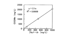
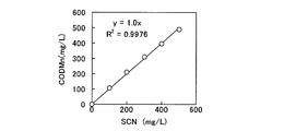
- FIG. 2A to FIG. 2C show the correlation based on the measured values of phenol concentration, thiosulfuric acid, thiocyanate and COD Mn concentration.
- oxygen consumption per 1 mg of phenol, thiosulfuric acid and thiocyanic acid was 2.1 mg, 0.48 mg and 1.0 mg, respectively.
- the known component concentrations when determining the correlation between the COD concentration without using a COD Cr, it is possible to use the analysis results of the COD Mn, risk and hazard as COD Cr There is an advantage that it is not necessary to perform analysis using a certain drug.
- theoretical oxygen consumption per mg of phenol, thiosulfuric acid and thiocyanic acid can be expressed by the following chemical reaction formulas (1) to (3): Is calculated to be 2.38 mg, 0.57 mg and 1.1 mg, respectively.
- the COD conversion step 4 is to convert the concentration of each component obtained in the analysis step 2 into a COD concentration by using the correlation 3.
- the reason for converting into COD concentration is because it is adopted as the most excellent scale in the activated sludge model. That is, as described in Non-Patent Document 1 described above, it is possible to express the relationship of a series of electron equivalents such as organic matter, living things or used oxygen by COD alone, and to obtain an oxygen balance. is there. Although it is possible to calculate each component concentration without converting it to the COD concentration, it is not practical because the above advantages can not be utilized.
- a sulfur compound such as thiosulfuric acid or thiocyanic acid can be converted to sulfur here for simulation, and can be reconverted to each component concentration in component concentration conversion step 12 described later.
- thiosulfuric acid and thiocyanic acid as sulfur components, it is possible to calculate sulfate ion components and the like which are not counted as COD. This makes it possible to track the mass balance of sulfur and to understand the behavior of the sulfur component. However, even if the mass balance of sulfur is obtained by sulfur conversion, since the mass balance of oxygen is obtained, it does not affect the simulation.
- bacteria that decompose sulfur compounds are generally considered to be sulfur-oxidizing bacteria, which are different from heterotrophic bacteria that decompose organic substances and are considered not to interact with each other.
- the accuracy is improved by separating and considering other components.
- the sulfur conversion value of 1 mg of thiosulfuric acid and thiocyanic acid is calculated to be 0.57 mg and 0.55 mg, respectively, from the chemical reaction formulas (2) to (3).
- conversion of the component concentration to COD is the same as the component concentration conversion step 12 described later by consistently using any one of theoretical oxygen consumption or COD Cr or COD Mn .
- parameter 5 the growth yield which is a stoichiometry parameter of each component and the saturation constant which is a kinetic equation parameter, the maximum specific growth rate, and the type and concentration of bacteria which degrade the compound component are used.
- the relative in vivo respiration rate of the organism under aerobic conditions to the reaction rate parameter, but since the effect is usually small, You do not have to set it.
- the parameter setting step 6 is roughly divided into (A) conducting experiments and analyzing experimental data under certain conditions, and (B) picking up literature values. It is preferable to set parameters according to the former. .
- the method (A) is described below. This method is determined by calibration using (a) the concentration of the compound component having biodegradability and the concentration of dissolved oxygen separately separately collected in time series in the inflowing wastewater and treated water. (A) The biological aerobic treatment is performed for each of the components individually, the dissolved oxygen concentration is continuously measured, and the oxygen consumption rate is calculated from the measured values, and the calculation is performed.
- the parameters are set in advance using any of the methods (a) or (b) of the methods determined from the data of oxygen consumption rate.
- time-series measured value data of (A) time-series data is obtained so that changes in concentration can be recognized.
- time-series data is obtained so that changes in concentration can be recognized.
- the time-series actual measurement data be stable.
- data in which the component concentration of the inflowing anssui, the composition, etc. fluctuate significantly during one week is not desirable.
- the fluctuation magnitude of the component concentration of Anshui inflowing at the time interval of simulation biological treatment time (residence time) is 5% The thing within the limits can be used.
- the method of determining by the calibration of the above (A) is not particularly specified, but for example, from the time series actual measurement value, the calculated value and the standard deviation of the time series actual measurement using the commercially available simulation software AQUASIM, the following arithmetic expression (2) : ⁇ Wherein ⁇ 2 (p) is the value of ⁇ 2 of the target model parameter p, and y meas, m is the measured value (component concentration or oxygen consumption rate) of the m th time series data, , Y m (p) are calculated values (component concentration or oxygen consumption rate) of the m-th time-series data when assuming the value of the model parameter p, ⁇ meas, m is the m-th time series The standard deviation of the actual value of the data or the standard deviation of the entire actual value, and n is the number of data points.
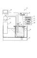
- the method of determining the parameters from the oxygen consumption rate data of the oxygen consumption rate test in the above (i) uses the test apparatus of FIG.
- a microbial sludge 22 used in a biological treatment process and a nitrification inhibitor 23 are added to the oxygen consumption rate test device 21 to suppress oxygen consumption when ammonia nitrogen is nitrified to nitrate nitrogen
- the liquid of the oxygen consumption rate test device 21 is mixed by a stirrer 24.
- the nutrient salt 25 may be added to prevent the decrease of the activity of the microorganism due to the deficiency of the nutrient salt.
- the target component 26 is added to the oxygen consumption rate test device 21, and the change with time of the dissolved oxygen concentration is measured by the dissolved oxygen concentration meter 27.
- Recording of the dissolved oxygen concentration may be performed by the data recording device 28.
- air may be supplied by the air supply device 29 when it falls below the control value.
- the pH may be measured with a pH meter 30, and an acid or alkali may be supplied and controlled by an acid / alkali supply device 31.
- a thermostatic water bath 33 provided with a heater 32 may be used.
- component A The method for determining the parameters from the change over time of the dissolved oxygen concentration and the oxygen consumption rate obtained by adding the target component (hereinafter referred to as component A) is not specified, but for example, the component for the growth yield From the COD conversion concentration of A and the oxygen consumption, the following arithmetic expression (3): ⁇ Wherein Y A is the growth yield of the bacteria that degrades component A, S A, COD is the COD equivalent concentration of component A, and O 2 meas is the actual value of oxygen consumption. Can be determined by
- the oxygen consumption rate by endogenous respiration is obtained in advance, and the oxygen consumption rate by endogenous respiration is subtracted from the measured value of the oxygen consumption, and the oxygen used for proliferation is determined.
- the consumption rate can be determined, the present invention does not particularly specify the method.
- the method of determining the value of the maximum specific growth rate and the saturation constant is not particularly specified, it can be determined, for example, by the method described in Non-Patent Document 2 described above. That is, after aeration of the microbial sludge used in the oxygen consumption rate test for 1 hour, the microbial sludge is mixed with the wastewater at various dilution rates, and the oxygen consumption rate is measured. Aeration control is performed to keep the dissolved oxygen concentration constant during measurement. Next, the specific oxygen consumption rate is determined by dividing the measured oxygen consumption rate by the sludge concentration, and the specific oxygen consumption rate minus the oxygen consumption rate due to endogenous respiration (specific substrate oxidation rate) is determined.
- the specific endogenous respiration rate is the oxygen consumption rate by endogenous respiration at the time of the organism's own decomposition, and how to obtain it is from the oxygen consumption rate when the component A is not added in the oxygen consumption rate test. Desired.
- ⁇ A is the specific growth rate of the bacteria that degrades component A
- Y A is the growth yield of the bacteria that degrades component A
- r OX is the specific substrate oxidation rate. The relationship shown in ⁇ holds.
- the value of S O2 / (K O2 + S O2 ) can be regarded as approximately 1 in order to maintain the dissolved oxygen concentration at a high concentration. Therefore, the specific growth rate can be regarded as a function of only the component concentration. From the above, a plot of the value of the specific growth rate ⁇ A obtained by the arithmetic expression (4) and the component concentration is obtained, and fitting the expression of the arithmetic expression (5) to the plot allows the maximum relative growth of the microorganism. The saturation constants for velocity and component A are determined.
- the method for determining the type and concentration of bacteria that degrades the compound component is not particularly specified, but it is desirable that the type basically corresponds to one type of bacteria for one component. Furthermore, if there is a possibility that one type of bacteria may decompose multiple components from experimental data and knowledge of literature, one type of bacteria may be added to the multiple components to improve calculation prediction and calculation prediction accuracy according to the actual phenomenon. May be set to correspond. However, although one type of component may be decomposed by multiple types of bacteria, they often exhibit the same type of decomposition action, and the amount of calculation increases by increasing the number of types of bacteria, so It is desirable to make one type of bacteria correspond.
- the oxygen consumption rate using the compound component is calculated by the following equation (6): Where OUR is the oxygen consumption rate, and X A is the concentration of bacteria that degrades component A, and Y A is the growth yield of bacteria that degrades component A, and K A is And S A is the saturation constant for the COD conversion value of the component A concentration, S A is the COD conversion concentration of the component A, K O 2 is the saturation constant for the dissolved oxygen concentration, and S O 2 is the dissolved oxygen concentration. In many cases, it is represented by ⁇ , and there is a method using this formula.
- the maximum specific growth rate, saturation constant for component A are determined by the aforementioned method, since the oxygen consumption rate test to maintain the dissolved oxygen concentration to a high concentration, S O2 / (K O2 The value of + S O2 ) can be regarded as approximately one. From this, the oxygen consumption rate is expressed only as a function of the concentration of bacteria which degrades component A. Therefore, X A can be determined by substituting the OUR actual value obtained in the oxygen consumption rate test into the equation (6).
- dissolved oxygen concentration 7 For dissolved oxygen concentration 7, install a dissolved oximeter in the biological treatment process, and use the value obtained by measuring the dissolved oxygen concentration in the biological reaction tank, or treat the dissolved oxygen concentration as a parameter in parameter setting step 6, Any method using values determined by calibration may be used.
- the COD concentration 11 of each component of the treated water is determined using the COD concentration 9, the dissolved oxygen concentration 7 and the parameter 5.
- the model used for the calculation calculates the COD concentration 11 of each component of the treated water according to the above-described arithmetic expression (1) based on the IWA activated sludge model.
- the COD concentration 11 of each component of the treated water can be reconverted to the component concentration value 13 of each component of the treated water by using the correlation 3 in the component concentration conversion step 12.
- a simulation including the effects of pH, alkalinity, ammonia concentration and the like may be performed.
- the calculation method is not specified, for example, hydrogen ion concentration, dissolved carbon dioxide concentration, ammonia concentration etc. are added to C i , stoichiometry parameters such as hydrogen ion concentration, dissolved carbon dioxide concentration, ammonia concentration etc. to P ij
- the reaction rate equation may be added to j j to perform the calculation.
- FIG. 1 is a block diagram showing the configuration and calculation flow of a water quality simulation method of a biological treatment process.
- a simulation method of a batch test for phenol, thiosulfuric acid, and thiocyanic acid as compound components having biodegradability will be described.
- the batch test added components to a 1 L reaction vessel so as to have a phenol concentration of 100 mg / L, a thiosulfuric acid concentration of 100 mg / L, and a thiocyanic acid concentration of 10 mg / L, and an MLSS concentration of 5000 mg / L.
- the dissolved oxygen concentration was measured by a dissolved oxygen meter, and the pH was measured by a pH meter. Further, the dissolved oxygen concentration was controlled to 3.25 mg / L and pH 7.5.
- the analysis step 2 is a step of analyzing the concentration of the component in the wastewater flowing into the biological treatment process, but here is the initial component concentration in the above-mentioned batch test apparatus, and it is calculated from the addition amount of each component
- the phenol concentration was confirmed by JIS K 0102 spectrophotometry, the concentration of thiosulfuric acid and thiocyanic acid was analyzed by ion chromatography, and the MLSS concentration was confirmed by the centrifugal separation method of Non-Patent Document 1 described above.
- the COD conversion process 4 is a COD conversion process which converts the concentration of phenol, thiosulfuric acid, and thiocyanic acid obtained in the analysis process 2 into a COD concentration.
- COD conversion conversion is performed according to the correlation 3 between phenol concentration, thiosulfuric acid concentration, and thiocyanic acid concentration and COD Mn concentration shown in FIG. 2A to FIG. 2C.
- the COD concentration of each component was converted to 11.
- the parameter setting step 6 sets parameters used in the calculation step 10.
- the parameter 5 set the growth yield, the maximum specific growth rate, the saturation constant, and the concentration of phenol-degrading bacteria, thiosulfate-decomposing bacteria and thiocyanate-decomposing bacteria used in the calculation step 10 described later.
- As a setting method as a result of examining the method of determining from the oxygen consumption rate data of the oxygen consumption rate test and the method by calibration, although the appropriate value was obtained in either case, it is obtained from the oxygen consumption rate test in this case. Since some variations were observed in the parameter values, a calibration method was used. The commercially available simulation software AQUASIM was used for calibration.
- the value of ⁇ 2 shown in the arithmetic expression (2) was determined, and the value of the parameter when the value of ⁇ 2 became the minimum was calculated. .
- the measured values were obtained as changes over time in component concentrations from batch tests for each component performed in advance.
- the calculated value was obtained by the method of calculation step 10 described later.
- the dissolved oxygen concentration 7 used the control value 3.25 mg / L of the batch test.
- the calculation process 10 simulates the time-dependent change of phenol, thiosulfuric acid, and thiocyanic acid concentration of a batch test using COD concentration 9 of each component of wastewater, dissolved oxygen concentration 7 and parameter 5 to calculate each component of treated water
- the COD concentration 11 was determined.
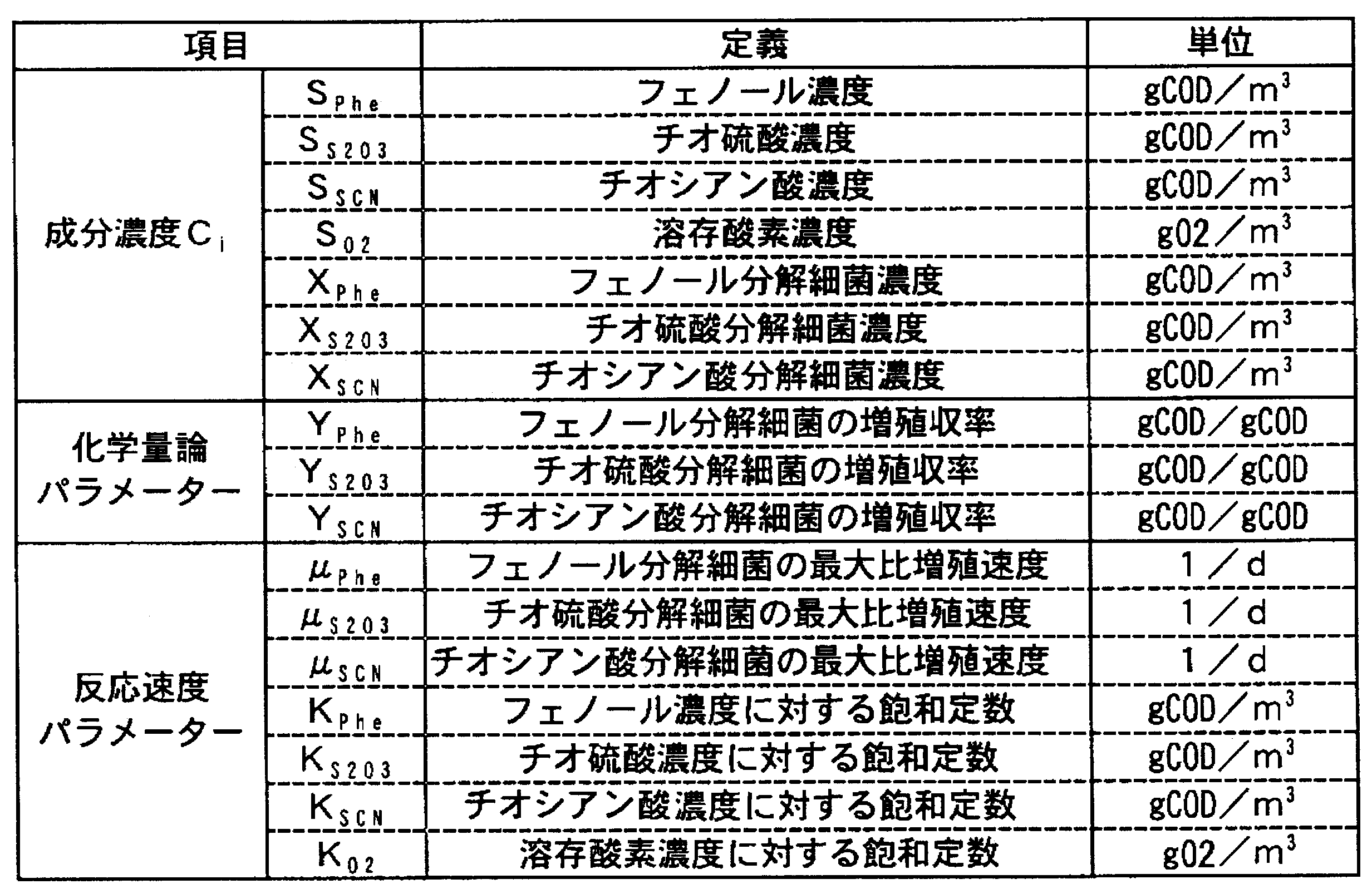
- the above-mentioned operation formula (1) was used. Table 1 below shows the concentration C i of each component, the stoichiometry parameter, and the reaction rate parameter used for the calculation.
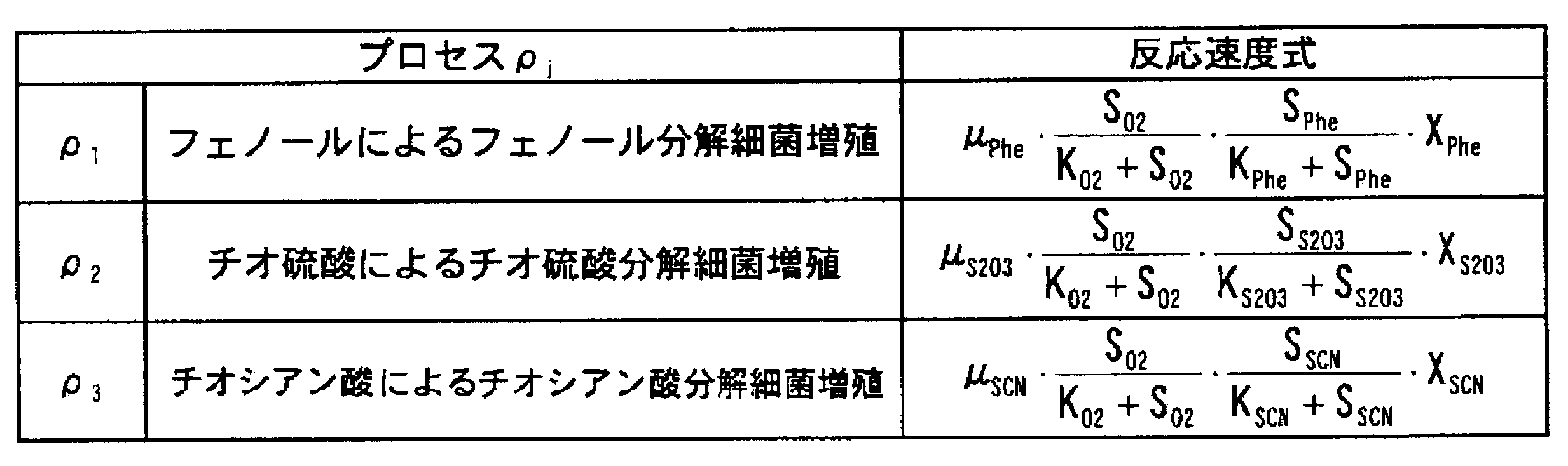
- the rate of increase of the phenol concentration is calculated by the following equation (7): ⁇
- S Phe is a phenol concentration
- t is a time
- S O 2 is a dissolved oxygen concentration
- K O 2 is a saturation constant for the dissolved oxygen concentration
- K Phe is for the phenol concentration
- the saturation constant is X Phe is the concentration of phenol degrading bacteria
- ⁇ Phe is the maximum specific growth rate of phenol degrading bacteria
- Y Phe is the growth yield of phenol degrading bacteria. It is represented by ⁇ .
- the component concentration conversion step 12 uses the correlation 3 between the concentrations of phenol, thiosulfuric acid, and thiocyanic acid and the COD concentration shown in FIGS. It reconverted to component concentration.
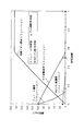
- FIG. 4 shows the time-dependent change of each component concentration in the batch test.
- the concentration of each component of the treated water is predicted by applying the activated sludge model in the biological aerobic treatment process of the waste water containing the biodegradable compound component. it can.
- the concentration of each component of treated water can be predicted whether it is a single component or a combination of two components.
- Example 2 Simulation of a batch test for phenol, thiosulfuric acid and thiocyanic acid (when one type of bacteria decomposes two components)
- a simulation method will be described when it is set that one type of bacteria (sulfur component-degrading bacteria) decomposes two components of thiosulfuric acid and thiocyanic acid in Example 1.
- sulfur component-degrading bacteria the reason for using thiosulfuric acid- and thiocyanate-degrading bacteria as sulfur component-degrading bacteria is that in actual processing, it was assumed that sulfur-component-degrading bacteria correspond to sulfur-oxidizing bacteria.
- the simulation is performed in the same flow as in FIG. 1, and the biodegradable compound components, batch test method, analysis step 2, parameter setting step 6, dissolved oxygen concentration 7 and component concentration conversion step 12 are performed in the same manner as in Example 1.
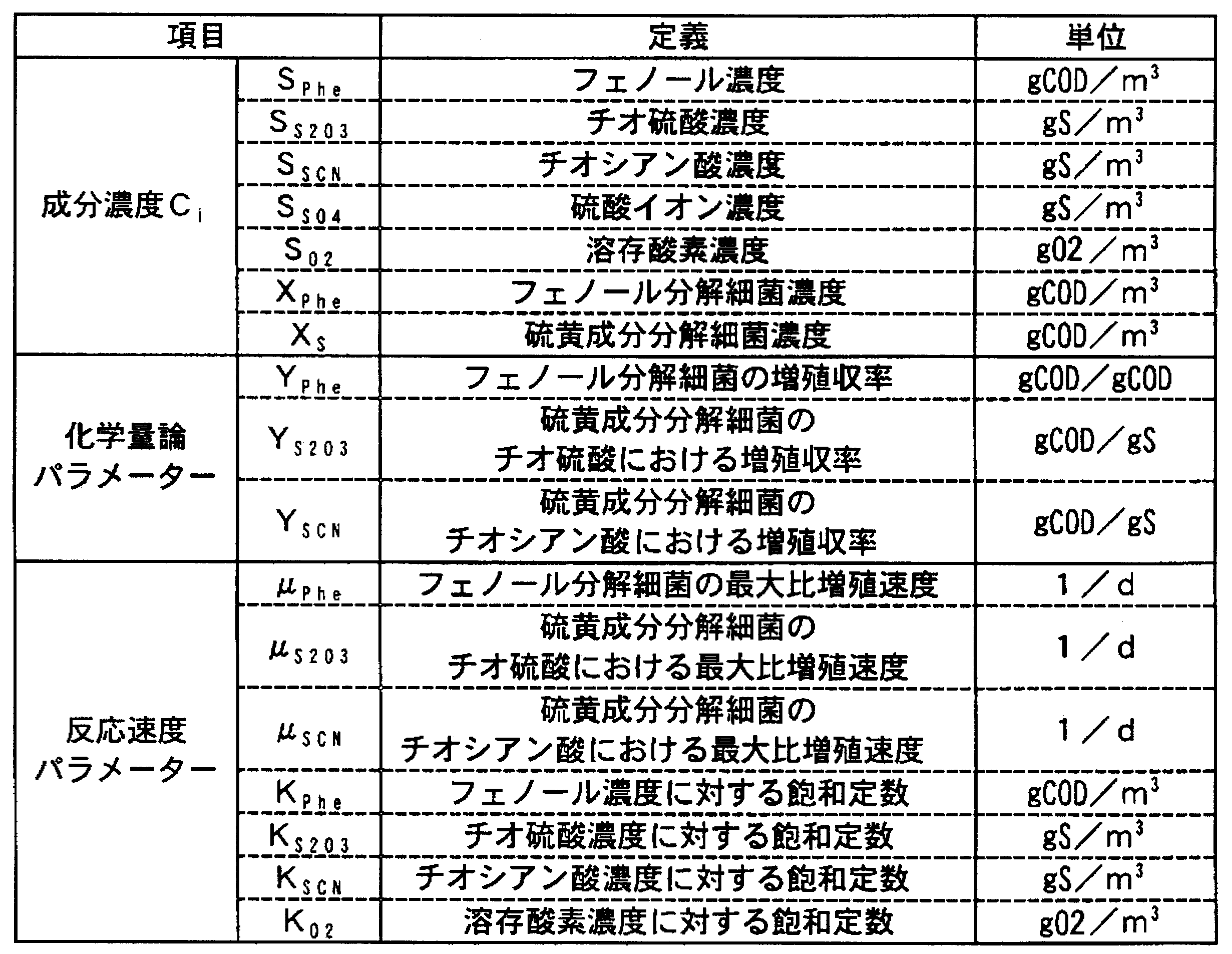
- the COD conversion process 4 and the component concentration conversion process 12 are changed to a sulfur conversion process, and the component concentration, the stoichiometry parameter and the reaction rate parameter of Table 1 are set as shown in Table 4 below.
- step 10 the thiosulfate degrading bacteria concentration and the thiocyanate degrading bacteria concentration are summarized in the sulfur component degrading bacteria concentration and are shown in Table 4 below:
- FIG. 5 shows the time-dependent change of each component concentration in the batch test.
- the degradation rate was increased for thiosulfate as compared to FIG. It has been calculated degrading bacteria concentration of each Example 1, thiosulfate degrading bacteria and (X S2O3) divided thiocyanate degrading bacteria (X SCN), in the present embodiment the two components of thiosulfate and thiocyanate because it sets decomposed with sulfur components decomposition bacteria one, mainly because the growth was concentrated in sulfur components decomposition bacterial concentration (X S) of thiosulfate degrading bacteria (X S2O3) and thiocyanate-degrading bacteria (X SCN) It is.
- one type of bacteria is used to degrade one component.
- one type of bacteria may be set to correspond to a plurality of components.
- concentration of thiosulfuric acid and thiocyanic acid it becomes possible to track the mass balance of sulfur, and it becomes possible to grasp the behavior of the sulfur component.
- calculation was performed taking into account the specific internal respiration rate, the result was in a negligible range, and no clear difference was seen.
- Example 3 Simulation of Oxygen Consumption Rate Test for Cresol
- the components were added to a 1 L reaction vessel so that the o-cresol concentration was 15 mg / L, and the MLSS concentration was 330 mg / L.
- the dissolved oxygen concentration was measured by a dissolved oxygen meter, and the pH was measured by a pH meter. Further, the dissolved oxygen concentration was controlled to 3.25 mg / L and pH 7.5.
- the analysis step 2 is a step of analyzing the concentration of components in the wastewater flowing into the biological treatment process.
- the concentration of the initial component in the above-mentioned oxygen consumption rate test device was checked, but the o-cresol concentration was confirmed by the JIS K 0102 absorptiometric method.
- the COD conversion step 4 is a COD conversion step of converting the concentration of o-cresol obtained in the analysis step 2 into a COD concentration.
- the parameter setting step 6 sets parameters used in the calculation step 10.
- the parameter 5 set the growth yield, the maximum specific growth rate, the saturation constant, and the concentration of cresol-degrading bacteria used in the calculation step 10 described later.
- the growth yield was determined by the operation equation (3) from the COD equivalent concentration of o-cresol and the oxygen consumption obtained from the oxygen consumption rate test. Specifically, since o-cresol was added to be 13 mg / L, the COD concentration is 3 to 32.7 mg / L in correlation.
- the rate of oxygen consumption during aeration was determined by performing linear approximation from the value of the rate of oxygen consumption during aeration and before and after aeration.
- the oxygen consumption rate 10 mg / L / hr at time t 1 the rate of oxygen consumption at time t 2 and 7.5 mg / L / hr, between the time t 1 of time t 2, when the aeration has been
- the oxygen consumption rate at time T between them the following arithmetic expression (8): ⁇ Wherein OUR T is the oxygen consumption rate at time T, t 1 is the time before aeration, t 2 is the time after aeration, and T is in the aeration period, It is the time you want to determine the rate of oxygen consumption. It asked using ⁇ . However, not only this but another approximation method may be used.
- the degrading bacteria corresponded to cresol degrading bacteria.
- the maximum specific growth rate, saturation constant, and cresol-degrading bacterial concentration are determined by a calibration method, and the value of ⁇ 2 shown in the equation (2) is determined from the measured value, the calculated value and the standard deviation of the measured value.
- the value of the parameter was calculated when the value of ⁇ 2 became the minimum.
- the measured values of the oxygen consumption rate and the component concentration were measured and determined during the oxygen consumption rate test in this example. The calculated value was obtained by the method of calculation step 10 described later.
- the dissolved oxygen concentration 7 used the control value 3.25 mg / L of the batch test.
- the calculation process 10 performed simulation about the time-dependent change of o-cresol concentration using COD concentration 9, dissolved oxygen concentration 7, and parameter 5, and determined COD concentration 11 of o-cresol of treated water.
- an arithmetic expression (1) was used as a calculation method. Table 7 below shows the concentrations and parameters of each component used in the calculation:
- the component concentration conversion step 12 converts the o-cresol COD concentration 11 of the treated water back into the o-cresol concentration 13 according to the correlation 3 between the o-cresol concentration and the COD concentration as in the COD conversion step 4.
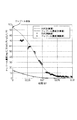
- the results of the above simulation are shown in FIG. FIG. 6 shows the time course of o-cresol concentration.
- the present invention is also applicable to components other than phenol, thiosulfuric acid and thiocyanic acid, and the component concentration can be determined even if correlation 3 is used for theoretical oxygen consumption. be able to.
- the present invention it is possible to calculate the component concentration of treated water by setting the type of bacteria that decomposes the soluble slow-decomposable component that was not the target in the activated sludge model. Yes, it is industrially useful.
Landscapes
- Life Sciences & Earth Sciences (AREA)
- Chemical & Material Sciences (AREA)
- Engineering & Computer Science (AREA)
- Biodiversity & Conservation Biology (AREA)
- Organic Chemistry (AREA)
- Health & Medical Sciences (AREA)
- Water Supply & Treatment (AREA)
- Environmental & Geological Engineering (AREA)
- Hydrology & Water Resources (AREA)
- Microbiology (AREA)
- Medicinal Chemistry (AREA)
- Immunology (AREA)
- Pathology (AREA)
- General Physics & Mathematics (AREA)
- General Health & Medical Sciences (AREA)
- Biochemistry (AREA)
- Analytical Chemistry (AREA)
- Physics & Mathematics (AREA)
- Food Science & Technology (AREA)
- Molecular Biology (AREA)
- Activated Sludge Processes (AREA)
- Purification Treatments By Anaerobic Or Anaerobic And Aerobic Bacteria Or Animals (AREA)
- Measuring Or Testing Involving Enzymes Or Micro-Organisms (AREA)
Abstract
Description
(1)流入廃水のCOD濃度を、溶解性不活性有機物、易分解性有機物、浮遊不活性有機物、遅分解性有機物等の性質によって分画し、それぞれCOD濃度ベースの変数と設定する;
(2)従属栄養生物の増殖や自己分解等のプロセスごとに、変数間の化学量論及びプロセスの反応速度式を設定する;
(3)化学量論係数及び反応速度定数のパラメーターを、酸素消費速度試験又は水質の実測データからのキャリブレーションにより決定する;
(4)シミュレーションを実行し、生物処理槽、処理水のCOD濃度等が算出される。
一方で、下水と異なる成分をもつ産業廃水や工場廃水等についても、生物学的処理プロセスによる産業廃水や工場廃水の処理が行われている。しかしながら、これらの廃水に対して、水質シミュレーション方法に活性汚泥モデルが適用された事例はない。
特に、製鉄所コークス工場から発生する廃水は安水と呼ばれ、フェノール、チオ硫酸、チオシアン酸を主成分とするが、これらは下水には含まれない成分であり、活性汚泥モデルの適用性について検討した事例は見られない。
味埜俊、活性汚泥モデル、日本、株式会社環境新聞社、2005年1月31日 J.S.Cech、J.Chudoba and P.Grau、Determination of Kinetic Constants of Activated Sludge Microorganisms、Water Science and Technology、Vol.17、pp.259-272、1984
前記したように、生物学的好気処理における水質シミュレーション方法として活性汚泥モデルが一般的であるが、産業廃水や工場廃水の生物学的好気処理に適用された事例はない。この原因として、以下の2点が挙げられる。
(1)活性汚泥モデルでは、下水のような複数成分が混合した廃水を生物学的好気処理する際の流入廃水と処理水のCOD濃度のみ予測するが、生物分解性を有する化合物成分の濃度は予測できないことが挙げられる。例えば、コークス製造過程で発生する安水では、安水中に含まれるフェノールが廃水基準項目の一つであり、フェノール濃度をシミュレーションにより予測する必要があるが、活性汚泥モデルでは特に安水のような複数成分が混合した廃水を生物学的好気処理した後の処理水中フェノール濃度を予測することが困難であるため、産業廃水や工場廃水に活性汚泥モデルを適用する意義は小さかった。
(2)産業廃水や工場廃水には、溶解性遅分解性の有機物(界面活性剤、例えば、直鎖アルキルベンゼンスルホン酸等)、または、無機物(例えば、チオ硫酸、チオシアン酸)が含まれる。しかしながら、活性汚泥モデルで対象としている都市下水中には分解速度の非常に遅い溶解性遅分解性成分はそれほど含まれておらず、モデルの酸素収支に与える影響を考慮していなかった。すなわち、そもそも溶解性遅分解性成分の概念が活性汚泥モデルには含まれていなかったため、産業廃水や工場廃水に活性汚泥モデルを適用することは困難であった。
本発明は、廃水中の成分ごとに分画し、成分ごとに成分を分解する細菌の種類および変数および反応プロセスを設定することで、活性汚泥モデルを利用した生物学的好気処理プロセスのシミュレーションが可能となり、処理水中の成分濃度を求め、さらに、溶解性遅分解性成分を含む廃水であっても、廃水中の成分ごとに分画するため、溶解性遅分解性成分という概念を用いること無しに、活性汚泥モデルを利用した生物学的好気処理プロセスのシミュレーションが可能となる、生物分解性のある化合物成分を含む産業廃水や工場廃水に適用可能な水質シミュレーション方法を提供することを目的とする。
[1]生物分解性を有する化合物成分を含む廃水を生物反応槽内で生物学的好気処理するプロセスにおける水質シミュレーション方法であって、
前記生物反応槽に流入する前記廃水中の前記化合物成分の各成分濃度を分析する分析工程と、
前記各成分濃度と、CODCr、CODMn及び理論的酸素消費量から選ばれる一つのCOD濃度との相関関係をもとに、各成分濃度の分析値を各成分のCOD濃度に換算するCOD換算工程と、
化学量論パラメーターである増殖収率、反応速度式パラメーターである飽和定数、最大比増殖速度、並びに前記化合物成分を分解する細菌の種類および濃度を設定するパラメーター設定工程と、
前記生物反応槽の溶存酸素濃度を測定する溶存酸素濃度測定工程と、
前記各成分のCOD濃度、前記増殖収率、前記飽和定数、前記最大比増殖速度、並びに前記化合物成分を分解する細菌の種類及び濃度、並びに溶存酸素濃度を用いて、下記演算式(1):

前記各成分濃度と、CODCr、CODMn及び理論的酸素消費量から選ばれる一つのCOD濃度との相関関係をもとに、当該算出された生物学的処理水の各成分のCOD濃度を、各成分濃度に換算する成分濃度換算工程とを、含む水質シミュレーション方法。
(ア)前記流入する廃水及び処理水において、事前に時系列的に別途採取したそれぞれの生物分解性を有する化合物成分濃度と溶存酸素濃度を用いて、キャリブレーションによって決定する方法、
(イ)前記各成分それぞれに対して、各成分単独で前記生物学的好気処理を行って連続的に溶存酸素濃度を測定し、当該測定値から酸素消費速度を算出し、当該算出された酸素消費速度のデータから決定する方法、のいずれかの方法を用いて、前記化学量論パラメーター及び前記反応速度パラメーターを設定する、前記[1]に記載の水質シミュレーション方法。
上記生物学的反応槽で上記生物学的好気処理した後の処理水における各成分の硫黄濃度を算出する硫黄計算工程と、
当該算出された生物学的処理水の各成分の硫黄濃度を、チオ硫酸濃度及びチオシアン酸濃度に再換算する硫黄再換算工程と
を有する、前記[1]又は[2]に記載の水質シミュレーション方法。
前記生物反応槽に流入する前記廃水中の前記化合物成分の各成分濃度を分析する分析手段と、
前記各成分濃度と、CODCr、CODMn及び理論的酸素消費量から選ばれる一つのCOD濃度との相関関係をもとに、各成分濃度の分析値を各成分のCOD濃度に換算するCOD換算手段と、
化学量論パラメーターである増殖収率、反応速度式パラメーターである飽和定数、最大比増殖速度、並びに前記化合物成分を分解する細菌の種類および濃度を設定するパラメーター設定手段と、
前記生物反応槽の溶存酸素濃度を測定する溶存酸素濃度測定手段と、
前記各成分のCOD濃度、前記増殖収率、前記飽和定数、前記最大比増殖速度、並びに前記化合物成分を分解する細菌の濃度及び溶存酸素濃度を用いて、下記演算式(1):

前記各成分濃度と、CODCr、CODMn及び理論的酸素消費量から選ばれる一つのCOD濃度との相関関係をもとに、当該算出された生物学的処理水の各成分のCOD濃度を、各成分濃度に換算する成分濃度換算手段とを、含む水質シミュレーション装置。
(ア)前記流入する廃水及び処理水において、事前に時系列的に採取したそれぞれの生物分解性を有する化合物成分濃度と溶存酸素濃度を用いて、キャリブレーションによって決定する手段、
(イ)前記各成分それぞれに対して、各成分単独で前記生物学的好気処理を行って連続的に溶存酸素濃度を測定し、当該測定値から酸素消費速度を算出し、当該算出された酸素消費速度のデータから決定する手段、のいずれかの手段を用いて、前記化学量論パラメーター及び前記反応速度式パラメーターを設定する、前記[4]に記載の水質シミュレーション装置。
上記生物学的反応槽で上記生物学的好気処理した後の処理水における各成分の硫黄濃度を算出する硫黄計算手段と、
当該算出された生物学的処理水の各成分の硫黄濃度を、チオ硫酸濃度及びチオシアン酸濃度に再換算する硫黄再換算手段と
を有する、前記[4]又は[5]に記載の水質シミュレーション装置。
本発明の奏する効果は以下のとおりである。
生物分解性を有する化合物成分を含む産業廃水や工場廃水に対して、流入廃水中の各成分濃度をCOD濃度に変換し、活性汚泥モデルを適用することで、処理水の各成分濃度が予測できる。また、活性汚泥モデルでは対象外であった溶解性遅分解性成分についても、その成分を分解する細菌の種類を設定することで、処理水の成分濃度を計算することが可能である。また、各成分濃度と、CODCr、CODMn及び理論的酸素消費量から選ばれる一つのCOD濃度との相関関係を求める際には、CODMnの分析結果を用いることができるので、CODCrのように危険かつ有害性のある薬品を用いた分析を行わなくてもよい。
溶解性成分は、生物分解性成分及び生物分解性がほとんど無い難分解性成分に分けられる。難分解性成分は、もともと生物分解が困難であり、濃度としても小さい。さらに、生物分解性成分は、分析による定性、定量が困難な未知成分が含まれるが、廃水中の割合として少量なため無視しても構わない。例えば安水では、フェノール、チオ硫酸、チオシアン酸以外の成分がこれに相当する。以上のことから、廃水における難分解性成分、及び、未知成分は無視しても、本発明の生物分解性を有する化合物成分の予測は可能である。
図1は、本発明による廃水の水質シミュレーション方法のフローを例示した図である。また、図中の各「工程」は各「手段」に替えることができ、廃水の水質シミュレーション装置を例示した図でもある。
また、生物学的好気処理とは、基質と細菌が存在し、ばっ気装置を有する反応槽において、ばっ気を行うことで溶存酸素を供給しながら、混合・撹拌を行うことで基質と細菌を接触・反応させることで、基質を分解処理する方法である。
このように、既知成分濃度と、COD濃度との相関関係を求める際には、CODCrを用いなくとも、CODMnの分析結果を用いることができるので、CODCrのように危険かつ有害性のある薬品を用いた分析を行わなくても良いという利点がある。
また、この他にも、各成分濃度とCOD濃度の相関関係を簡易に得る方法として、成分の理論的酸素消費量を化学反応式から算出する方法もある。たとえば、フェノール、チオ硫酸、チオシアン酸1mgあたりの理論的酸素消費量は、以下の化学反応式(1)~(3):



パラメーター5としては、各成分の化学量論パラメーターである増殖収率及び反応速度式パラメーターである飽和定数、最大比増殖速度並びに前記化合物成分を分解する細菌の種類及び濃度を用いる。
また、生物学的処理において生物自身の自己分解が与える影響を加味するため、反応速度パラメーターに好気条件下における生物の比内生呼吸速度を設定しても良いが、通常は影響が少ないので、設定しなくてもよい。
上記(A)の方法について以下に述べる。この方法は、(ア)前記流入する廃水及び処理水において、事前に時系列的に別途採取したそれぞれの生物分解性を有する化合物成分濃度と溶存酸素濃度を用いて、キャリブレーションによって決定する方法、(イ)前記各成分それぞれに対して、各成分単独で前記生物学的好気処理を行って連続的に溶存酸素濃度を測定し、当該測定値から酸素消費速度を算出し、当該算出された酸素消費速度のデータから決定する方法のうち(ア)又は(イ)のいずれかの方法を用いて、事前にパラメーターを設定する。




以下、本発明の実施の形態を図に基づいて説明する。図1は、生物学的処理プロセスの水質シミュレーション方法の構成と計算の流れを示したブロック図である。
以下、生物分解性のある化合物成分としてフェノール、チオ硫酸、チオシアン酸を対象としたバッチ試験のシミュレーション方法について説明する。バッチ試験は、1Lの反応容器に、フェノール濃度100mg/L、チオ硫酸濃度100mg/L、チオシアン酸濃度10mg/Lとなるよう成分を添加し、MLSS濃度は5000mg/Lで行った。試験中は、溶存酸素濃度計により溶存酸素濃度を測定し、pH計によりpHを測定した。また、溶存酸素濃度を3.25mg/L、pH7.5に制御した。
パラメーター5は、増殖収率、最大比増殖速度、飽和定数、及び後述する計算工程10で用いるフェノール分解細菌濃度、チオ硫酸分解細菌濃度及びチオシアン酸分解細菌濃度を設定した。設定方法は、酸素消費速度試験の酸素消費速度データから決定する方法、及び、キャリブレーションによる方法を検討した結果、いずれも妥当な値が得られたが、今回のケースでは酸素消費速度試験から得られたパラメーター値に多少のばらつきが見られたため、キャリブレーションによる方法を用いた。キャリブレーションには市販のシミュレーションソフトAQUASIMを用いた。具体的には、実測値、計算値及び実測値の標準偏差から、演算式(2)に示されるχ2の値を求め、χ2の値が最小となったときのパラメーターの値を算出した。実測値は、事前に行った成分ごとのバッチ試験から、成分濃度の経時変化を得た。計算値は、後述する計算工程10の方法により求めた。
計算工程10は、廃水の各成分のCOD濃度9、溶存酸素濃度7及びパラメーター5を用いて、バッチ試験のフェノール、チオ硫酸、チオシアン酸濃度の経時変化のシミュレーションを行い、処理水の各成分のCOD濃度11を求めた。計算方法は、前記演算式(1)を用いた。以下の表1に、計算に用いる各成分濃度Ci及び化学量論パラメーター、反応速度パラメーターを示す。


以下、実施例1においてチオ硫酸、チオシアン酸の2成分を1種類の細菌(硫黄成分分解細菌)が分解すると設定した時のシミュレーション方法について説明する。ここで、チオ硫酸、チオシアン酸分解細菌を硫黄成分分解細菌としたのは、実際の処理では、硫黄成分分解細菌は硫黄酸化細菌が相当すると推測されたためである。

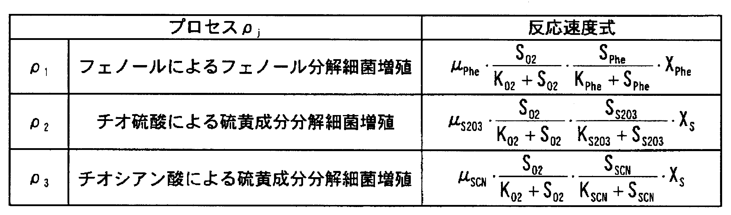
ここで、実施例1と本実施例のいずれが良いかは、実験値と計算値との比較や、実際の現象に近い反応が計算できているか等によって判断し、選択することが望ましい。本実施例においては、計算値の精度向上が可能となったと考えられた。
以下、生物分解性のある有機物成分としてo-クレゾールを対象とした酸素消費速度試験のシミュレーション方法について説明する。
酸素消費速度試験は、1Lの反応容器に、o-クレゾール濃度15mg/Lとなるよう成分を添加し、MLSS濃度は330mg/Lで行った。試験中は、溶存酸素濃度計により溶存酸素濃度を測定し、pH計によりpHを測定した。また、溶存酸素濃度を3.25mg/L、pH7.5に制御した。

パラメーター5は、増殖収率、最大比増殖速度、飽和定数、及び後述する計算工程10で用いるクレゾール分解細菌濃度を設定した。設定方法は、増殖収率をo-クレゾールのCOD換算濃度と、酸素消費速度試験から得られた酸素消費量から演算式(3)によって求めた。具体的には、o-クレゾールを13mg/Lとなるよう添加したので、COD濃度は相関関係3から32.7mg/Lとなる。

計算工程10は、COD濃度9、溶存酸素濃度7及びパラメーター5を用いて、o-クレゾール濃度の経時変化についてシミュレーションを行い、処理水のo-クレゾールのCOD濃度11を求めた。計算方法は、演算式(1)を用いた。以下の表7は、計算に用いる各成分濃度及びパラメーターを示す:
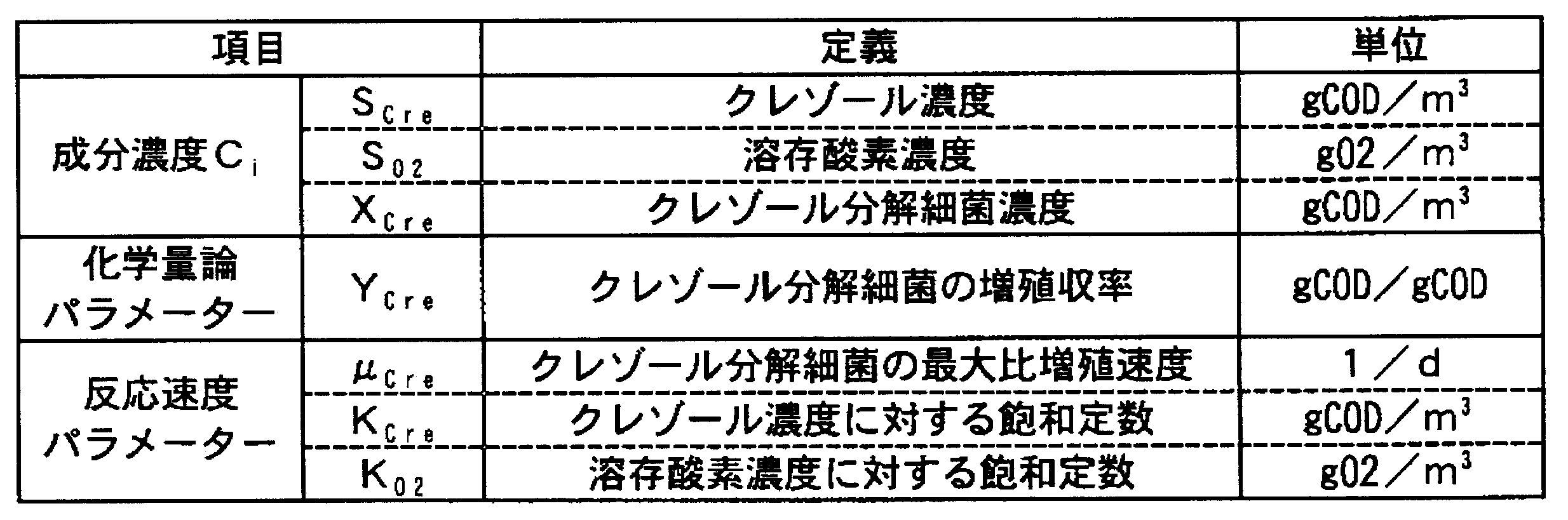


上記のシミュレーションの結果を図6に示す。図6は、o-クレゾール濃度の経時変化を示す。以上述べたように、本実施例によれば、フェノール、チオ硫酸、チオシアン酸以外の成分にも本発明が適用可能であり、相関関係3に理論的酸素消費量を用いても成分濃度を求めることができる。
本発明によれば、活性汚泥モデルでは対象外であった溶解性遅分解性成分についても、その成分を分解する細菌の種類を設定することで、処理水の成分濃度を計算することが可能であり、産業上有用である。
1 水質シミュレーション方法の概要図
2 分析工程
3 各成分とCOD濃度との相関関係
4 COD換算工程
5 パラメーター
6 パラメーター設定工程
7 溶存酸素濃度
8 溶存酸素濃度測定工程
9 COD濃度
10 計算工程
11 処理水の各成分COD濃度
12 成分濃度換算工程
13 処理水の各成分濃度
21 酸素消費速度試験装置
22 微生物汚泥
23 硝化阻害剤
24 撹拌装置
25 栄養塩
26 対象成分
27 溶存酸素濃度計
28 データ記録装置
29 空気供給装置
30 pH計
31 酸・アルカリ供給装置
32 ヒーター 33 恒温水槽
Claims (6)
- 生物分解性を有する化合物成分を含む廃水を生物反応槽内で生物学的好気処理するプロセスにおける水質シミュレーション方法であって、
前記生物反応槽に流入する前記廃水中の前記化合物成分の各成分濃度を分析する分析工程と、
前記各成分濃度と、CODCr、CODMn及び理論的酸素消費量から選ばれる一つのCOD濃度との相関関係をもとに、各成分濃度の分析値を各成分のCOD濃度に換算するCOD換算工程と、
化学量論パラメーターである増殖収率、反応速度式パラメーターである飽和定数、最大比増殖速度、並びに前記化合物成分を分解する細菌の種類および濃度を設定するパラメーター設定工程と、
前記生物反応槽の溶存酸素濃度を測定する溶存酸素濃度測定工程と、
前記各成分のCOD濃度、前記増殖収率、前記飽和定数、前記最大比増殖速度、並びに前記化合物成分を分解する細菌の種類及び濃度、並びに溶存酸素濃度を用いて、下記演算式(1):

前記各成分濃度と、CODCr、CODMn及び理論的酸素消費量から選ばれる一つのCOD濃度との相関関係をもとに、当該算出された生物学的処理水の各成分のCOD濃度を、各成分濃度に換算する成分濃度換算工程とを、含む水質シミュレーション方法。 - 前記パラメーター設定工程は、
(ア)前記流入する廃水及び処理水において、事前に時系列的に別途採取したそれぞれの生物分解性を有する化合物成分濃度と溶存酸素濃度を用いて、キャリブレーションによって決定する方法、
(イ)前記各成分それぞれに対して、各成分単独で前記生物学的好気処理を行って連続的に溶存酸素濃度を測定し、当該測定値から酸素消費速度を算出し、当該算出された酸素消費速度のデータから決定する方法、のいずれかの方法を用いて、前記化学量論パラメーター及び前記反応速度式パラメーターを設定する、請求項1に記載の水質シミュレーション方法。 - 上記廃水が、コークス製造工程で発生する安水であり、上記化合物成分のうち、有機物成分はフェノール、並びに、無機物成分はチオ硫酸及びチオシアン酸であり、
チオ硫酸、チオシアン酸のシミュレーションについては、上記COD換算工程の代わりにチオ硫酸及びチオシアン酸濃度を硫黄換算する硫黄換算工程と、
上記生物学的反応槽で上記生物学的好気処理した後の処理水における各成分の硫黄濃度を算出する硫黄計算工程と、
当該算出された生物学的処理水の各成分の硫黄濃度を、チオ硫酸濃度及びチオシアン酸濃度に再換算する硫黄再換算工程と
を有する、請求項1又は2に記載の水質シミュレーション方法。 - 生物分解性を有する化合物成分を含む廃水を生物反応槽内で生物学的好気処理するプロセスで用いる水質シミュレーション装置であって、
前記生物反応槽に流入する前記廃水中の前記化合物成分の各成分濃度を分析する分析手段と、
前記各成分濃度と、CODCr、CODMn及び理論的酸素消費量から選ばれる一つのCOD濃度との相関関係をもとに、各成分濃度の分析値を各成分のCOD濃度に換算するCOD換算手段と、
化学量論パラメーターである増殖収率、反応速度式パラメーターである飽和定数、最大比増殖速度、並びに前記化合物成分を分解する細菌の種類および濃度を設定するパラメーター設定手段と、
前記生物反応槽の溶存酸素濃度を測定する溶存酸素濃度測定手段と、
前記各成分のCOD濃度、前記増殖収率、前記飽和定数、前記最大比増殖速度、並びに前記化合物成分を分解する細菌の種類及び濃度、並びに溶存酸素濃度を用いて、下記演算式(1):

前記各成分濃度と、CODCr、CODMn及び理論的酸素消費量から選ばれる一つのCOD濃度との相関関係をもとに、当該算出された生物学的処理水の各成分のCOD濃度を、各成分濃度に換算する成分濃度換算手段と
を、含む水質シミュレーション装置。 - 前記パラメーター設定手段は、
(ア)前記流入する廃水及び処理水において、事前に時系列的に別途採取したそれぞれの生物分解性を有する化合物成分濃度と溶存酸素濃度を用いて、キャリブレーションによって決定する手段、
(イ)前記各成分それぞれに対して、各成分単独で前記生物学的好気処理を行って連続的に溶存酸素濃度を測定し、当該測定値から溶存酸素濃度を算出し、当該算出された酸素消費速度のデータから決定する手段、のいずれかの手段を用いて、前記化学量論パラメーター及び前記反応速度式パラメーターを設定する、請求項4に記載の水質シミュレーション装置。 - 上記廃水が、コークス製造工程で発生する安水であり、上記化合物成分のうち、有機物成分はフェノール、並びに、無機物成分はチオ硫酸及びチオシアン酸であり、
チオ硫酸、チオシアン酸のシミュレーションについては、上記COD換算手段の代わりにチオ硫酸及びチオシアン酸濃度を硫黄換算する硫黄換算手段と、
上記生物学的反応槽で上記生物学的好気処理した後の処理水における各成分の硫黄濃度を算出する硫黄計算手段と、
当該算出された生物学的処理水の各成分の硫黄濃度を、チオ硫酸濃度及びチオシアン酸濃度に再換算する硫黄再換算手段と
を有する、請求項4又は5に記載の水質シミュレーション装置。
Priority Applications (4)
| Application Number | Priority Date | Filing Date | Title |
|---|---|---|---|
| JP2010537685A JP5435658B2 (ja) | 2008-11-14 | 2009-11-10 | 水質シミュレーション方法及び装置 |
| KR1020117010511A KR101233623B1 (ko) | 2008-11-14 | 2009-11-10 | 수질 시뮬레이션 방법 및 장치 |
| BRPI0921825A BRPI0921825A2 (pt) | 2008-11-14 | 2009-11-10 | processo e dispositivo para simular a qualidade da água |
| CN2009801447683A CN102209688B (zh) | 2008-11-14 | 2009-11-10 | 水质模拟方法和装置 |
Applications Claiming Priority (2)
| Application Number | Priority Date | Filing Date | Title |
|---|---|---|---|
| JP2008-292519 | 2008-11-14 | ||
| JP2008292519 | 2008-11-14 |
Publications (1)
| Publication Number | Publication Date |
|---|---|
| WO2010055642A1 true WO2010055642A1 (ja) | 2010-05-20 |
Family
ID=42169788
Family Applications (1)
| Application Number | Title | Priority Date | Filing Date |
|---|---|---|---|
| PCT/JP2009/005993 Ceased WO2010055642A1 (ja) | 2008-11-14 | 2009-11-10 | 水質シミュレーション方法及び装置 |
Country Status (5)
| Country | Link |
|---|---|
| JP (1) | JP5435658B2 (ja) |
| KR (1) | KR101233623B1 (ja) |
| CN (1) | CN102209688B (ja) |
| BR (1) | BRPI0921825A2 (ja) |
| WO (1) | WO2010055642A1 (ja) |
Cited By (5)
| Publication number | Priority date | Publication date | Assignee | Title |
|---|---|---|---|---|
| JP2011045872A (ja) * | 2009-07-31 | 2011-03-10 | Nippon Steel Corp | 安水の生物学的好気処理におけるcod濃度シミュレーション方法及び装置 |
| CN111125936A (zh) * | 2020-01-09 | 2020-05-08 | 广州市市政工程设计研究总院有限公司 | 污水设计水质与模型水质的转换方法、系统及存储介质 |
| CN114047228A (zh) * | 2021-11-09 | 2022-02-15 | 同济大学 | 一种沉积物耗氧污染物的解析装置及方法 |
| CN114112593A (zh) * | 2021-12-02 | 2022-03-01 | 中国科学院生态环境研究中心 | 指示水中cod值的测试方法 |
| CN119430509A (zh) * | 2024-11-21 | 2025-02-14 | 金剑环保集团有限公司 | 一种可提升式曝气装置及污水处理系统 |
Families Citing this family (4)
| Publication number | Priority date | Publication date | Assignee | Title |
|---|---|---|---|---|
| CN105300751B (zh) * | 2014-07-16 | 2018-02-27 | 鞍钢股份有限公司 | 一种废水化学需氧量检测前预处理系统及方法 |
| KR101662736B1 (ko) * | 2015-01-28 | 2016-10-06 | 한국지질자원연구원 | 시간에 따른 광산배수 수질 특성 변화 예측방법 |
| US20210355007A1 (en) * | 2018-12-13 | 2021-11-18 | Sembcorp Industries Ltd. | System and method for predicting a parameter associated with a wastewater treatment process |
| CN110451661B (zh) * | 2019-09-12 | 2021-07-30 | 南京大学 | 一种污水中微生物类溶解性有机氮的预测模型及其应用 |
Citations (2)
| Publication number | Priority date | Publication date | Assignee | Title |
|---|---|---|---|---|
| JP2001334253A (ja) * | 2000-05-30 | 2001-12-04 | Toshiba Corp | 水質シミュレータ |
| JP2008142704A (ja) * | 2006-11-15 | 2008-06-26 | Kobelco Eco-Solutions Co Ltd | 生物学的水処理のシミュレーション方法およびシミュレーション装置 |
Family Cites Families (4)
| Publication number | Priority date | Publication date | Assignee | Title |
|---|---|---|---|---|
| CN1257118C (zh) * | 2004-05-19 | 2006-05-24 | 天津大学 | 气井采出废水达标排放的集成化处理工艺 |
| JP5255818B2 (ja) | 2007-11-05 | 2013-08-07 | 株式会社神鋼環境ソリューション | シミュレーション方法 |
| JP4278701B1 (ja) | 2007-06-19 | 2009-06-17 | 株式会社神鋼環境ソリューション | シミュレーション方法、シミュレーション装置、生物処理方法、ならびに、生物処理装置 |
| CN101269896A (zh) * | 2008-05-08 | 2008-09-24 | 南京大学 | 一种工业园区综合废水达标处理的方法 |
-
2009
- 2009-11-10 CN CN2009801447683A patent/CN102209688B/zh not_active Expired - Fee Related
- 2009-11-10 KR KR1020117010511A patent/KR101233623B1/ko not_active Expired - Fee Related
- 2009-11-10 WO PCT/JP2009/005993 patent/WO2010055642A1/ja not_active Ceased
- 2009-11-10 BR BRPI0921825A patent/BRPI0921825A2/pt not_active Application Discontinuation
- 2009-11-10 JP JP2010537685A patent/JP5435658B2/ja not_active Expired - Fee Related
Patent Citations (2)
| Publication number | Priority date | Publication date | Assignee | Title |
|---|---|---|---|---|
| JP2001334253A (ja) * | 2000-05-30 | 2001-12-04 | Toshiba Corp | 水質シミュレータ |
| JP2008142704A (ja) * | 2006-11-15 | 2008-06-26 | Kobelco Eco-Solutions Co Ltd | 生物学的水処理のシミュレーション方法およびシミュレーション装置 |
Non-Patent Citations (1)
| Title |
|---|
| TAKASHI MINO: "IWA Kassei Odei Model Dai 3 Kai Ryunyusui Bunkaku to Calibration", EICA, vol. 8, no. 1, 15 June 2003 (2003-06-15), pages 61 - 68 * |
Cited By (8)
| Publication number | Priority date | Publication date | Assignee | Title |
|---|---|---|---|---|
| JP2011045872A (ja) * | 2009-07-31 | 2011-03-10 | Nippon Steel Corp | 安水の生物学的好気処理におけるcod濃度シミュレーション方法及び装置 |
| CN111125936A (zh) * | 2020-01-09 | 2020-05-08 | 广州市市政工程设计研究总院有限公司 | 污水设计水质与模型水质的转换方法、系统及存储介质 |
| CN111125936B (zh) * | 2020-01-09 | 2024-01-30 | 广州市市政工程设计研究总院有限公司 | 污水设计水质与模型水质的转换方法、系统及存储介质 |
| CN114047228A (zh) * | 2021-11-09 | 2022-02-15 | 同济大学 | 一种沉积物耗氧污染物的解析装置及方法 |
| CN114047228B (zh) * | 2021-11-09 | 2023-08-04 | 同济大学 | 一种沉积物耗氧污染物的解析装置及方法 |
| CN114112593A (zh) * | 2021-12-02 | 2022-03-01 | 中国科学院生态环境研究中心 | 指示水中cod值的测试方法 |
| CN114112593B (zh) * | 2021-12-02 | 2023-08-25 | 中国科学院生态环境研究中心 | 指示水中cod值的测试方法 |
| CN119430509A (zh) * | 2024-11-21 | 2025-02-14 | 金剑环保集团有限公司 | 一种可提升式曝气装置及污水处理系统 |
Also Published As
| Publication number | Publication date |
|---|---|
| CN102209688B (zh) | 2013-01-23 |
| JPWO2010055642A1 (ja) | 2012-04-12 |
| BRPI0921825A2 (pt) | 2016-01-12 |
| JP5435658B2 (ja) | 2014-03-05 |
| CN102209688A (zh) | 2011-10-05 |
| KR101233623B1 (ko) | 2013-02-14 |
| KR20110074577A (ko) | 2011-06-30 |
Similar Documents
| Publication | Publication Date | Title |
|---|---|---|
| JP5435658B2 (ja) | 水質シミュレーション方法及び装置 | |
| Sepehri et al. | Activity enhancement of ammonia-oxidizing bacteria and nitrite-oxidizing bacteria in activated sludge process: metabolite reduction and CO2 mitigation intensification process | |
| Wang et al. | Enhanced biological nitrogen removal under low dissolved oxygen in an anaerobic-anoxic-oxic system: Kinetics, stoichiometry and microbial community | |
| Wu et al. | Simulation and optimization of a coking wastewater biological treatment process by activated sludge models (ASM) | |
| Wett et al. | The role of inorganic carbon limitation in biological nitrogen removal of extremely ammonia concentrated wastewater | |
| Tallec et al. | Nitrous oxide emissions from secondary activated sludge in nitrifying conditions of urban wastewater treatment plants: effect of oxygenation level | |
| Blackburne et al. | Kinetic characterisation of an enriched Nitrospira culture with comparison to Nitrobacter | |
| Blackburne et al. | Determination of growth rate and yield of nitrifying bacteria by measuring carbon dioxide uptake rate | |
| Lotti et al. | Physiological and kinetic characterization of a suspended cell anammox culture | |
| Liu et al. | Probing the stoichiometry of the nitrification process using the respirometric approach | |
| Vadivelu et al. | Effect of free ammonia and free nitrous acid concentration on the anabolic and catabolic processes of an enriched Nitrosomonas culture | |
| Li et al. | Long-term partial nitrification in an intermittently aerated sequencing batch reactor (SBR) treating ammonium-rich wastewater under controlled oxygen-limited conditions | |
| Jiménez et al. | Effect of pH and nitrite concentration on nitrite oxidation rate | |
| Tang et al. | Nitrification at full-scale municipal wastewater treatment plants: Evaluation of inhibition and bioaugmentation of nitrifiers | |
| Domingo-Felez et al. | Modelling N2O dynamics of activated sludge biomass: uncertainty analysis and pathway contributions | |
| Rodríguez et al. | Monitoring the removal of nitrogen by applying a nitrification–denitrification process in a Sequencing Batch Reactor (SBR) | |
| Pala-Ozkok et al. | Characteristics of mixed microbial culture at different sludge ages: effect on variable kinetics for substrate utilization | |
| Ciudad et al. | Differential kinetics of ammonia-and nitrite-oxidizing bacteria: a simple kinetic study based on oxygen affinity and proton release during nitrification | |
| Wu et al. | Effect of nitrifiers enrichment and diffusion on their oxygen half-saturation value measurements | |
| Liwarska-Bizukojc et al. | A new approach to determine the kinetic parameters for nitrifying microorganisms in the activated sludge systems | |
| Gapes et al. | Online titrimetric and off-gas analysis for examining nitrification processes in wastewater treatment | |
| Di Trapani et al. | Attached and suspended biomass kinetics in an IFAS-MBR system operated under intermittent aeration: Long-term monitoring under SRT variation | |
| JP5175647B2 (ja) | 水質予測方法及び生物処理方法 | |
| Zhang et al. | NOB suppression by organic pollutants in mainstream single-stage partial nitrification/anammox (PN/A) process: Experimental evidence and modelling investigation | |
| JP4922214B2 (ja) | 水処理方法及び水処理装置 |
Legal Events
| Date | Code | Title | Description |
|---|---|---|---|
| WWE | Wipo information: entry into national phase |
Ref document number: 200980144768.3 Country of ref document: CN |
|
| 121 | Ep: the epo has been informed by wipo that ep was designated in this application |
Ref document number: 09825896 Country of ref document: EP Kind code of ref document: A1 |
|
| ENP | Entry into the national phase |
Ref document number: 2010537685 Country of ref document: JP Kind code of ref document: A |
|
| ENP | Entry into the national phase |
Ref document number: 20117010511 Country of ref document: KR Kind code of ref document: A |
|
| NENP | Non-entry into the national phase |
Ref country code: DE |
|
| WWE | Wipo information: entry into national phase |
Ref document number: 3683/DELNP/2011 Country of ref document: IN |
|
| 122 | Ep: pct application non-entry in european phase |
Ref document number: 09825896 Country of ref document: EP Kind code of ref document: A1 |
|
| ENP | Entry into the national phase |
Ref document number: PI0921825 Country of ref document: BR Kind code of ref document: A2 Effective date: 20110510 |