WO2010052778A1 - レーザ駆動装置、信号処理回路及び情報記録装置 - Google Patents
レーザ駆動装置、信号処理回路及び情報記録装置 Download PDFInfo
- Publication number
- WO2010052778A1 WO2010052778A1 PCT/JP2008/070206 JP2008070206W WO2010052778A1 WO 2010052778 A1 WO2010052778 A1 WO 2010052778A1 JP 2008070206 W JP2008070206 W JP 2008070206W WO 2010052778 A1 WO2010052778 A1 WO 2010052778A1
- Authority
- WO
- WIPO (PCT)
- Prior art keywords
- signal
- order
- trigger
- transition
- change
- Prior art date
- Legal status (The legal status is an assumption and is not a legal conclusion. Google has not performed a legal analysis and makes no representation as to the accuracy of the status listed.)
- Ceased
Links
Images






Classifications
-
- G—PHYSICS
- G11—INFORMATION STORAGE
- G11B—INFORMATION STORAGE BASED ON RELATIVE MOVEMENT BETWEEN RECORD CARRIER AND TRANSDUCER
- G11B7/00—Recording or reproducing by optical means, e.g. recording using a thermal beam of optical radiation by modifying optical properties or the physical structure, reproducing using an optical beam at lower power by sensing optical properties; Record carriers therefor
- G11B7/12—Heads, e.g. forming of the optical beam spot or modulation of the optical beam
- G11B7/125—Optical beam sources therefor, e.g. laser control circuitry specially adapted for optical storage devices; Modulators, e.g. means for controlling the size or intensity of optical spots or optical traces
- G11B7/126—Circuits, methods or arrangements for laser control or stabilisation
-
- G—PHYSICS
- G11—INFORMATION STORAGE
- G11B—INFORMATION STORAGE BASED ON RELATIVE MOVEMENT BETWEEN RECORD CARRIER AND TRANSDUCER
- G11B7/00—Recording or reproducing by optical means, e.g. recording using a thermal beam of optical radiation by modifying optical properties or the physical structure, reproducing using an optical beam at lower power by sensing optical properties; Record carriers therefor
- G11B7/004—Recording, reproducing or erasing methods; Read, write or erase circuits therefor
- G11B7/0045—Recording
- G11B7/00456—Recording strategies, e.g. pulse sequences
Definitions
- the present invention is provided in an information recording apparatus that records information by irradiating an information recording medium such as an optical disk with laser light, and controls the laser driving apparatus that controls irradiation while changing the output of the laser light,
- the present invention belongs to a technical field of a signal processing circuit provided in a laser driving device and an information recording device provided with the laser driving device.
- a recording mark or a recording pit is formed on the optical disc by irradiating a laser beam from the laser diode toward the optical disc.
- a constant power supply voltage is supplied from the power supply to the laser diode so that an operation voltage necessary for the operation of the laser diode is applied.
- the waveform and power of the laser light emitted from the laser diode are controlled by the operation of a laser driver circuit including a transistor and the like.
- the waveform and power pattern of laser light that has been multi-leveled and pulse-divided are referred to as a write strategy.
- a plurality of current sources for supplying a current for irradiating a laser diode with laser light having a plurality of powers are provided, and current supply from the current source is directly switched by a control input corresponding to each current source.
- a so-called conventional method in which the current supplied to the laser diode is changed to change the power of the laser light of the laser diode.
- an NRZI (Non Return to Zero Inversion) signal indicating a mark length and a clock signal serving as a reference of the NRZI signal are transmitted to the laser driving device.
- a configuration including a strategy block that generates an internal clock with a sufficiently short interval by multiplying the clock and reproduces the strategy pattern by counting the internal clock.
- the control signal for switching the supply of current from the current source also needs to be a narrow pulse. Therefore, there is a technical problem that signal transmission becomes relatively difficult.
- the supply of current from one current source is turned off and the supply of current from another current source is started. It may be required to switch the current supply.
- signal transmission needs to be strictly managed. For example, a technical problem has been pointed out that when a time shift occurs in the control to a plurality of current sources, an excess or loss of power occurs in the laser light.
- the strategy block built-in type has a configuration that generates a narrow pulse signal and a configuration that changes the current based on the pulse signal both inside the laser drive device, so timing management is relatively easy There is an advantage that can be done.
- the frequency of the internal clock signal generated by multiplication processing or the like is increased (that is, increased in speed) based on the external clock signal, and a high-speed clock is generated.
- the circuit that generates the internal pulse signal according to the signal also becomes large. For this reason, the processing amount of the entire laser driving device increases, and as a result, the amount of heat generation increases and the chip area increases.
- the present invention has been made in view of, for example, the above-described conventional problems. For example, various powers of laser light can be obtained by a relatively small circuit configuration while keeping a pulse width of a control signal at a predetermined length or more. It is an object of the present invention to provide a laser driving device capable of realizing a write strategy corresponding to a change.
- a laser driving apparatus includes an irradiation unit that irradiates laser light having a power corresponding to a set value, a storage unit that holds a plurality of preset values that are set in advance, and the setting Order defining means for defining the order of transition between values, trigger means for obtaining a trigger signal indicating a timing of transition from one set value to another set value among the plurality of set values; Order change means for obtaining an order change signal for instructing the advancing direction of the order of transition between set values, and at a timing according to a change in the signal level of the trigger signal, is set according to the signal level of the order change signal Output determining means for determining the set value to be output based on the order of transition between the set values, and converting the determined set value into an analog signal for output to the irradiation means. And a DA converter circuit.
- a signal processing circuit is connected to the above-described laser driving device, and includes a trigger signal supply unit that supplies the trigger signal to the trigger unit, and a sequence change unit. The order change signal is supplied.
- an information recording apparatus of the present invention includes the above-described laser driving device.
- FIG. 1 is a block diagram conceptually showing a basic configuration example of an LD driver according to an embodiment. It is a figure which shows an example of the write strategy by LD driver concerning a present Example. It is a figure which shows an example of the write strategy by LD driver concerning a present Example. It is a figure which shows an example of the write strategy by LD driver concerning a present Example. It is a figure which shows an example of the write strategy by LD driver concerning a present Example. It is a figure which shows an example of the write strategy by LD driver concerning a present Example. It is a figure which shows an example of the write strategy by LD driver concerning a present Example. It is a figure which shows an example of the write strategy by LD driver concerning a present Example. It is a figure which shows an example of the write strategy by LD driver concerning a present Example. It is a figure which shows an example of the write strategy by LD driver concerning a present Example. It is a figure which shows an example of the write strategy by LD driver concerning a present
- 1 Information recording device 10 LD driver, 11 Trigger signal determination unit, 12 Order change signal processing unit, 13 Sequencer, 14 selector, 15 Power value holding unit, 16 DAC, 17 output buffer, 18 output selector, 20 signal processing circuit, 21 trigger signal generator, 22 order change signal generator, 30 host computer, 40 Laser diode
- An embodiment according to the laser driving device of the present invention includes an irradiation unit that irradiates a laser beam having a power corresponding to a setting value, a storage unit that holds a plurality of setting values that are set in advance, and a transition between the setting values.
- order defining means for defining the order
- a trigger means for obtaining a trigger signal indicating a timing of transition from one set value to another set value among the plurality of set values
- Order change means for obtaining an order change signal for instructing the traveling direction of the transition order, and the set value set in accordance with the signal level of the order change signal at a timing according to a change in the signal level of the trigger signal
- Output determining means for determining the set value to be output based on the order of transitions between them, and DA conversion for converting the determined set value into an analog signal and outputting the analog signal to the irradiation means.
- the order of transitions between is defined.
- the setting value is changed from one set value to another set value.
- the set value of the laser beam power is changed in accordance with the order of transition.
- the changed set value of the laser beam power is input to the irradiation means through the DA conversion circuit, and the laser beam is irradiated with the power corresponding to the set value.
- the set value of the power of the laser beam is a set value set in advance corresponding to each of the plurality of powers and stored in the storage unit in order to cause the irradiation unit to irradiate the laser beam with a plurality of powers.
- a setting value that is output based on the order of transition between setting values to be described later is determined (in other words, read) by the output determining means, and is output to the DA converter circuit.
- the order of transition between setting values is a meaning indicating the order of transition when transitioning from one setting value to another setting value among the plurality of setting values described above, and preferably the order
- the defining means uniquely defines each of the plurality of setting values.
- the same set values may be set in different orders in an overlapping manner.
- the order of transition between the setting values is in addition to the order of A ⁇ B ⁇ C ⁇ A or C ⁇ B ⁇ A ⁇ C.
- the order in which the same set value appears a plurality of times in a series of flows such as A ⁇ B ⁇ A ⁇ C ⁇ A, may also be defined.
- the output set value changes according to the order of transition between the above set values.
- a set value indicating the power of a new laser beam is output to the DA converter circuit, and as a result, the power of the irradiated laser beam transitions.
- the trigger signal is, for example, a pulse-like signal having a binary signal level indicating the timing of executing the laser beam power transition (that is, the transition of the set value).
- the transition of the set value is executed in accordance with the rising or falling timing of the trigger signal. Therefore, a desired write strategy can be realized by adjusting the preset setting value and the order of transition between the set values.
- the power of the laser light can be changed in accordance with a predetermined order of transition in accordance with a change in the signal level of the trigger signal that is, for example, pulsed.
- the order of transition of setting values corresponding to various write strategies can be defined in advance by adjusting the order of transition between setting values. Compared with a conventional LDD having a built-in block, a write strategy with a smaller logic can be realized.
- the order of transition between the set values is changed based on the state (for example, signal level) of the order change signal acquired by the order changing unit.
- the reordering signal is typically a signal having a binary signal level, and is typically allowed to change its state over a long span as compared to the trigger signal described above.
- the forward direction of the transition order between set values is designated as one of forward or reverse feed Control is performed such as skipping and jumping to a predetermined order.
- a so-called sequence abort control may be performed in which a series of set value transitions are aborted and a predetermined set value is set.
- the order change can be performed by setting the order of transition between set values to be treated as reverse feed.
- the above-described effect can be obtained without setting the mode of change of the signal level of the signal as strictly as the mode of change of the signal level of the trigger signal.
- the set value is transitioned by the previous trigger signal (that is, forward feed).
- the order changing means may be configured, for example, to be able to acquire a plurality of order changing signals.
- each control described above can be performed according to a combination of states such as signal levels of the plurality of order changing signals. It may be configured to be implemented. With this configuration, more complicated transition order change control can be realized, and more various write strategies can be realized by using a transition order composed of fewer setting values.
- the trigger unit that controls the timing of the transition of the set value and the order change unit that controls the change of the order of the transition between the set values By the operation, it is possible to realize a transition between a relatively large number of setting values by using a transition order constituted by a relatively small number of setting values set in advance. Accordingly, various write strategies can be realized even with a relatively small logic configuration.
- the output determination means is output based on the order of transition between the set values only at the timing when the signal level of the trigger signal changes. Determine the setting value.
- the set value transition described above is performed only at the timing when the signal level of the trigger signal changes (for example, when the trigger signal rises or when the trigger signal falls). In other words, the transition of the set value is not performed, for example, due to a change in the state of the order change signal.
- the order change signal includes: (i) a signal that instructs one of forward and reverse feeds in the direction of progress of the transition between the set values; and (ii) including a signal instructing to abort the transition, which temporarily applies the predetermined set value and starts the next series of laser beam irradiation at the predetermined set value.
- the order of transition of the set values can be designated as forward or backward by control using the order change signal acquired by the order change means.
- the order change signal acquired by the order change means for example, if it is configured to control whether the progress of the transition sequence is forward or backward according to a change in the state of the sequence change signal, the transition of a specific set value in the sequence of transitions is repeated. The operation can be instructed relatively easily.
- the setting value is A ⁇ B ⁇ A ⁇ B.
- the setting value is changed in the order of A ⁇ B ⁇ C ⁇ B ⁇ A.
- the order change signal it is possible to repeatedly use the power setting value while widening the interval of state change of the order change means. For this reason, it is possible to reduce the register set for temporarily storing the power setting value necessary for the configuration of the multi-pulse waveform (in other words, for switching from the low power setting value to the high power setting value). Therefore, a desired write strategy can be realized with a relatively small circuit configuration.
- the order change signal may be configured to perform control such that the order of transition of set values is skipped to a predetermined set value.
- a certain power setting value can be inserted only in a specific mark length.
- the predetermined setting value to be skipped to the state before the start of the mark portion, the series of laser light irradiation is finished, and the setting value is determined to the predetermined value without following the normal transition order. In other words (in other words, the order of transition is skipped to a predetermined value), a so-called abort operation can be realized.
- a series of laser light irradiations means, for example, laser light irradiations for forming each data mark portion defined according to a signal recorded on a recording medium, and is also referred to as a sequence. (Hereinafter referred to as a sequence).
- the irradiation unit is configured to irradiate the laser beam with a predetermined power.
- it may be configured to hold the set value before the abort and to perform the transition of the set value from the held set value at the start of the next sequence. This also makes it possible to realize a variety of write strategies with a small circuit configuration.
- the order change signal includes (i) a signal that instructs the traveling direction of the order of the transition to one of the forward feed and the reverse feed, and (ii) a signal that instructs the abort of the transition.
- the output determining means may be configured to apply the order change signal at a predetermined timing set in advance after the order change signal reaches a predetermined signal level.
- the signal level of the trigger signal that first changes in signal level after the order change signal is turned on (specifically, for example, the signal level of the order change signal becomes high).
- the control by the order change signal is executed after a predetermined timing after the order change signal is turned on. For example, after the signal level of the trigger signal is changed in a state where the order change of the set value is instructed by the order change signal, in fact, at the timing when the signal level of the second trigger signal changes, Control is performed so that the order of transition of setting values is changed.
- control timing designation by the order change signal may be configured to be performed only for the order change signal indicating a predetermined instruction (for example, sequence termination).
- the timing may be specified only for an arbitrary order change signal, and the timing may be specified for all the order change signals.
- an order change signal indicating sequence interruption is input so as to be executed at a timing when the signal level of the trigger signal after several changes, after the signal level change of the trigger signal in which the sequence interruption is recognized,
- the state of the sequence change signal may be ignored until the next sequence start. If comprised in this way, it can suppress suitably that the state of the order change signal after an abort instruction
- the current sequence is completed regardless of the state of the reordering signal at the time of the relatively fast and continuous power change in response to the abort instruction specified in the wide power change interval.
- it does not affect the next sequence there is enough time for the sequence change signal to change from the end state to the initial state, and therefore a relatively low-speed sequence change signal can be used.
- the output determining unit is configured to change the transition between the set values according to the signal level of the order change signal at the start of a series of laser light irradiation. Change the order.
- the setting value determined at the start of the sequence and the order of transition of the set value determined next are changed.
- the value that the set value can take is the first set value in the order of transition of the set value.
- the value that the set value can take is the next set value in the order of transition of the set value. That is, when the sequence is in the initial state, there is no need to control the change of the order of the set value transition by the order change signal.
- the interpretation of the order change signal at the start of the sequence for example, the first set value at the start of the sequence and the order of transition of the subsequent set values can be specified in advance. I can do it. More specifically, for example, the sequence can be changed to start from a desired set value by skipping the order of transition of the set value.
- the storage means holds the order of transition between the plurality of set values
- the output determining means is adapted to change the signal level of the trigger signal.
- the set value to be output is determined based on any one of the order of transition between the plurality of set values.
- a desired write strategy can be realized by using the order of transition between a plurality of setting values set in advance.
- a write strategy waveform that is actually used can be classified into several types according to the state of power transition in one sequence.
- waveforms for example, multi-pulse type, L type, and castle type write strategies are known.
- the outline of the waveform differs depending on the mark length of the mark portion where data is recorded. For example, even for a castle type write strategy, a relatively short mark mark portion is recorded with a monopulse, and a long mark portion is recorded with a so-called castle type.
- sequence pattern the sequence of transitions between a plurality of set values corresponding to the expected state of power transition (hereinafter referred to as a sequence pattern) is stored in the storage means in advance, and the sequence pattern used at the start of the sequence Therefore, a suitable write strategy can be realized relatively easily (for example, by simply changing the set value in accordance with the change in the signal level of the trigger signal).
- a plurality of types of sequence patterns may be prepared according to each mark length so as to be applied from the start to the end of one sequence.
- the sequence is automatically ended (that is, the laser beam is irradiated with a predetermined power). Setting value to be determined).
- various write strategies can be realized by the order change control by the order change signal even if only a relatively small number of sequence patterns are prepared. For example, for a multi-pulse type write strategy or the like, it is possible to cope with write strategies having different mark lengths by repeating the transition of predetermined set values by order change control. Conversely, terminating the sequence by the above-described aborting operation or the like during the sequence pattern also leads to the realization of various write strategies.
- the selection of the sequence pattern may be performed based on an order change signal acquired by the order change means, for example, as part of the order change of the set value transition, or under some other control. May be.
- sequence pattern may be configured to select a preset setting value, and may be configured such that a setting value to be determined can be selected in the order in which the signal level of a predetermined trigger signal changes. May be.
- the plurality of DA conversion circuits and the plurality of analog signals respectively output from the plurality of DA conversion circuits are actually supplied to the irradiation unit.
- Output selection means for selecting the analog signal to be output is further provided, and the output determination means may be determined at a timing when the next trigger signal changes for the plurality of DA conversion circuits. While the set value is input, the output selection unit is actually output to the irradiation unit based on the order of transition between the set values at the timing when the signal level of the next trigger signal changes. Select an analog signal.
- a set value that may be determined at the timing when the signal level of the next trigger signal changes based on the order of transition between the set values is input in advance to each of a plurality of DA conversion circuits. Is done.
- the trigger signal signal level changes depending on the time required for signal processing (for example, settling time) in the DA converter circuit. It is possible to favorably reduce the time lag that occurs before the set value is applied to.
- a setting value that may be determined next is input in advance to each of a plurality of DA converter circuits, and signal processing in each DA converter circuit is advanced. I can do it. If comprised in this way, based on the state of a subsequent order change signal and a trigger signal, by selecting and outputting the analog signal which shows the setting value actually output to an irradiation means, it is suitable for a trigger signal. It is possible to suppress time lag from the acquisition until the set value is actually applied. As described above, since the order change signal is acquired sufficiently ahead of the trigger signal to which the order change signal is actually applied, it is actually output even after checking the state of the order change signal. Can be selected.
- the trigger unit acquires the plurality of trigger signals, and the setting is performed based on at least one of the trigger signals. The timing at which the value transitions is indicated.
- the transition of the set value is performed at each timing when the signal levels of the plurality of trigger signals change. More specifically, a plurality of trigger signals output from a plurality of signal circuits are transmitted through corresponding signal lines. Then, the set value is determined at a timing determined by determination of a signal level such as edge extraction in each trigger signal.
- the transition timing of the set values adjacent in order is set. Since the trigger signals can be indicated by different trigger signals, it is possible to relax the strictness of changes in the signal level of each trigger signal. Specifically, for example, even in a write strategy that requires output of a trigger signal at an interval of a pulse width of 0.2T, another change occurs at a timing after 0.2T following a change in the signal level of one trigger signal. This can be suitably handled by changing the signal level of the trigger signal. Furthermore, in this case, it is not necessary to suppress the pulse width of each trigger signal to, for example, 0.2 T or less. Therefore, a desired write strategy can be realized even with a relatively low speed circuit.
- the trigger means acquires a slice level signal used for determination of the trigger signal in addition to the trigger signal.
- a slice level signal indicating a threshold value for determining the signal level of the trigger signal is acquired together with the trigger signal which is a pulse signal. More specifically, in addition to a signal line for transmitting a trigger signal, a signal line for transmitting a slice level signal is provided. For example, a slice level signal for determining a trigger signal at a timing synchronized with the trigger signal. Is transmitted.
- the single-ended transmission method that specifies the timing of transition of the set value of the optical power has a technical problem that the accuracy of the write strategy is lowered. This phenomenon is caused by a difference in the level to be sliced between the pulse signal sending side and the receiving side.
- the slice level signal on the signal sending side is transmitted together with the trigger signal. Then, at the timing when the signal level of the trigger signal exceeds or falls below the signal level of the slice level (that is, the timing at which the waveforms of the trigger signal and the slice level signal intersect), the setting value determination process is performed. At this time, both the trigger signal level and the slice level are determined on the signal sender side, so even if there is a difference in power supply voltage or ground level between the sender side and the receiver side, Therefore, it is possible to perform slicing at a level that satisfies the above-described condition, and it is possible to suppress fluctuations in the pulse width due to the above-described time shift of the trigger signal. As a result, a desired write strategy can be suitably realized.
- the level of the trigger signal sent from a single sender is the same, so a single slice level using only one signal line. If the signal is transmitted, the above-described effects can be enjoyed. For this reason, compared with the differential transmission mode described in detail later, fluctuations in the pulse width due to the above-described time lag of the trigger signal can be suppressed with a configuration using fewer signal lines. As a result, a desired write strategy can be suitably realized.
- the output determination means is output at a timing when any one of a rising edge and a falling edge in a waveform of the trigger signal exceeds a slice level. Determine the setting value.
- the signal level at the rising edge of the waveform exceeds (that is, exceeds) the slice level, and the signal level at the falling edge of the waveform is sliced.
- the set value to be output is determined at any one of the timing of exceeding (that is, decreasing) the level.
- differential signals such as LVDS (Low voltage differential) have been used for transmission of signals that transition at a relatively high speed. More specifically, in an operation signal such as LVDS, two signal lines that transmit signals of opposite phases are used, and the signal level of one signal line exceeds the signal level of the other signal line. It is set to be “1” and “0” when below.
- LVDS Low voltage differential
- By using such a differential signal it is possible to eliminate fluctuations in the pulse width due to the time shift of signal detection in the single-end signal described above.
- the above-described temporal deviation appears only in one direction, so that fluctuations in pulse width can be suitably eliminated while using a single-ended transmission method.
- two signal lines in differential transmission, it is necessary to transmit the pulse signal itself in order to transmit the pulse signal. Is needed.
- the differential transmission mode is not used and two signal lines are used (that is, when the above-described mode including a plurality of trigger means is used)
- the signal determination timing is set as in this mode.
- the start and end of the pulse signal can be expressed by the rise or fall of the signal on each independent signal line, the pulse width of each signal is affected if attention is paid to the timing of signal input. Restrictions are relatively relaxed.
- the embodiment of the signal processing circuit of the present invention is connected to the above-described embodiment of the laser driving apparatus of the present invention (including various aspects thereof), and the trigger supplies the trigger signal to the trigger means.
- a signal supply means and the order change signal are supplied to the order change means.
- the above-described trigger signal and order change signal can be suitably supplied. If comprised in this way, each effect of the laser drive device mentioned above can be enjoyed suitably.
- Embodiments according to the information recording apparatus of the present invention include the above-described embodiments according to the laser driving apparatus of the present invention (including various aspects thereof).
- the information recording apparatus of the present invention it is possible to suitably record information on an information recording medium such as an optical disk while enjoying the effects of the laser driving apparatus described above.
- the irradiation unit, the storage unit, the order defining unit, the trigger unit, the order changing unit, the output determining unit, and the DA converter circuit Prepare.
- the signal processing circuit according to the present embodiment includes trigger signal supply means and order change signal supply means.
- the information recording apparatus according to the present embodiment includes the laser driving apparatus according to the present embodiment. Therefore, it is possible to realize a write strategy corresponding to various power changes of the laser light with a relatively small circuit configuration while keeping the pulse width in the control signal at a predetermined length or more.
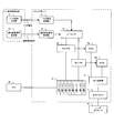
- FIG. 1 is a block diagram conceptually showing the structure of an LD driver 10 which is an example of the laser driving device in this embodiment.
- the LD driver 10 is typically provided inside the optical pickup 52 (see FIG. 10), and is connected to a laser diode (LD) 40 that is also provided in the optical pickup 52. Therefore, the LD driver 10 can control the irradiation power and timing of the laser light in the LD 40 according to the write strategy, as will be described in detail later.
- LD laser diode
- the LD driver 10 is typically connected to a signal processing circuit 20 provided on a main board on which the optical pickup 52 is provided. For this reason, as described in detail later, it is possible to receive an input of a trigger signal or an order change signal using an external clock or the like. As shown in FIG. 1, the LD driver 10 receives an input of an external trigger signal and processes the trigger signal, and receives an input of an order change signal from the outside.
- the sequence change signal processing unit 12 that processes the change signal, the sequencer 13 for controlling the change in the power value of the laser beam LB emitted from the laser diode 40 based on the trigger signal and the sequence change signal, and the sequencer 13 Under the control of, a selector 14 that selects the power value of the selected laser beam LB, and a power value holding unit 15 that stores a setting value corresponding to the power value and for setting each of a plurality of power values.
- a DAC (Digital Analog Converter) 16 for receiving the power value from the selector 14 and outputting the power value to the laser diode 40, and an output buffer Configured with a 17.
- the trigger signal processing unit 11 is a specific example of “trigger means” in the present embodiment, and is connected to a trigger signal generation unit 21 that generates a trigger signal in the signal processing circuit 20 and receives an input of the trigger signal. . Therefore, the trigger signal processing unit 11 performs signal processing such as edge extraction using a predetermined slice level, for example, on the input trigger signal, which is typically a pulse-like signal. Get the timing of the change.
- the transmission of the trigger signal is preferably performed using, for example, a known differential transmission method using two signal lines for one trigger signal. On the other hand, it may be configured to be performed by a single end method using one signal line for one trigger signal.
- the trigger signal generation unit 21 may be configured to generate a plurality of trigger signals each specifying individual timing.
- the trigger signal processing unit 11 is configured to receive each input of a plurality of trigger signals and acquire the timing of power change by performing signal processing on each individual trigger signal. Preferably it is.
- a plurality of trigger signal generation units 21 each generating a single trigger signal and a plurality of trigger signal processing units 11 each processing a single trigger signal are provided. It may be provided.
- the trigger signal generation unit 21 may be configured to generate a slice level signal used for signal processing such as edge extraction of the trigger signal together with the trigger signal.
- a signal line for transmitting a slice level signal corresponding to or common to a signal line for transmitting one or a plurality of trigger signals is provided. It is preferable.
- the trigger signal processing unit 11 performs a rising edge of the trigger signal when performing signal processing such as edge extraction on the input trigger signal, which is typically a pulse signal.
- signal processing such as edge extraction on the input trigger signal, which is typically a pulse signal.
- it may be configured to detect only at least one of the falling edges.
- the power value is changed only at the timing when the signal level exceeds the slice level at one of the rising edge and the falling edge with respect to the input of the trigger signal.
- the rise and fall (that is, power value change) timing of the monopulse waveform is specified by the rise or fall of two trigger signals. Just do it. At this time, it is not necessary to generate a trigger signal having a pulse width equal to that of the monopulse signal.
- the power value change timing is specified by a larger number of trigger signals as described above, the trigger signal pulse can be applied to a write strategy in which the power value changes relatively rapidly. The write strategy can be realized while keeping the width constant.
- the order change signal processing unit 12 is a specific example of the “order change unit” in the present embodiment, and is connected to the order change signal generation unit 22 that generates the order change signal in the signal processing circuit 20. Receives signal input. Therefore, the order change signal processing unit 12 performs signal processing such as detecting the signal level of the input order change signal, which is typically a pulse-like signal, so that the power value change order (to be described later) Hereinafter, a control signal for controlling (described as a sequence pattern) is input to the sequencer 13.
- an instruction to indicate the progress of a sequence pattern of power values set in advance in the sequencer 13 (for example, progress including forward feed, reverse feed, and skip of order), on an optical disc Instructing the determination of the initial power value of the laser beam at the start of irradiation in the irradiation (that is, the sequence) of the laser beam to one mark portion, and instructing the abort of the change in the power value in one sequence, etc.
- the transmission of the order change signal is preferably performed by using, for example, a known differential transmission method using two signal lines for one trigger signal. On the other hand, it may be configured to be performed by a single end method using one signal line for one trigger signal.
- the sequencer 13 is a specific example of a part constituting each of the “order defining unit” and the “output determining unit” in the present embodiment.
- the sequencer 13 defines the sequence pattern of the power value, and from the trigger signal processing unit 11. Based on the input trigger signal and the control signal input from the order change signal processing unit 12, the selector 14 described later is instructed to change the power value. More specifically, a sequence pattern of one or a plurality of power values is preliminarily defined and stored in an information storage unit such as a memory provided inside, and the trigger signal acquired by the trigger signal processing unit 11 is stored in the information storage unit. At the timing of the power change shown, the selector 14 is instructed to select the power value along the sequence pattern or along the sequence pattern to which control by the order change signal is added.
- the information storage means for storing the sequence pattern may be in any form as long as the sequence pattern can be referred to by the sequencer 13 and the selector 14 can be instructed to change the power. Is.
- the sequencer 13 may be configured to define and store a plurality of different sequence patterns. When configured in this way, the sequencer 13 may be configured to determine a sequence pattern to be applied in the sequence based on, for example, the state of the order change signal at the start of one sequence.
- it may be configured to include a plurality of sequencers 13 that define and store different sequence patterns.
- the selector 14 is a specific example of a portion constituting the “output determining means” in the present embodiment, and receives a power value change instruction from the sequencer 13 and determines one power value from a plurality of power values. Output to the DAC 16.
- the power value holding unit 15 is typically a storage element such as a register in which a plurality of power values are stored in advance.
- the DAC 16 is a specific example of the “DA conversion circuit” in the present embodiment.
- the DAC 16 receives a drive signal indicating a power value from the selector 14, converts the signal into an analog signal, and then outputs the laser diode via the output buffer 17. It is the structure which outputs to 40.
- the power value predicted to be determined at the timing indicated by the next trigger signal based on the sequence pattern stored in the sequencer 13 is transferred from the selector 14 to the DAC 16 at least before the actual trigger signal is input. It may be configured to be input.
- the LD driver 10 of the present embodiment it is possible to perform power control of laser light applied to a wider variety of write strategies while having a relatively small circuit configuration.
- the write strategy when recording data can be classified into several types according to the state of change of the power value in one sequence.
- write strategies for example, L-type, multi-pulse type, and castle type write strategies are known.
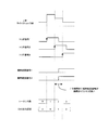
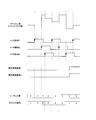
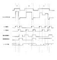
- FIGS. 2 to 4 respectively show the L-type, multi-pulse type, and castle type write strategy waveforms, the trigger signal by the LD driver 10 according to the present embodiment for realizing the write strategy waveforms, and It is a figure which shows an example of the aspect of an order change signal.
- the timing of the change in the power value of the laser beam is specified using three individual trigger signals 1 to 3. .
- the progress of the power value sequence pattern is controlled by using the two order change signals 1 and 2 individually and in combination.
- the change in the signal level of the trigger signals 1 to 3 (specifically, , The sequence value indicating the order of the power values in the sequence pattern is added one by one by the rising edge), while the signal level of the order change signal 1 is high and the signal level of the order change signal 2 is low.
- the sequence value is controlled to be subtracted one by one by the change in the signal level of the trigger signals 1 to 3.
- FIGS. 2 to 4 when the signal levels of the trigger signals 1 to 3 change while both the signal levels of the order change signals 1 and 2 are both high, the sequence value is changed.
- Control is performed so that a so-called censoring operation is performed. That is, in this embodiment, the mode of the power value change due to the change in the signal level of each of the trigger signals 1 to 3 is changed according to the state of the order change signals 1 and 2. Therefore, as shown in the figure, the target trigger signals 1 to 3 (that is, the trigger signal that rises at the timing when the sequence value is set to 0, the trigger signal 3 in FIG. 2, the trigger signal 2 in FIG. 3, and the trigger signal 2 in FIG. The trigger signal 1) immediately before the trigger signal (specifically, the trigger signal 2 in FIG. 2, the trigger signal 1 in FIG. 3, the trigger signal 3 in FIG. 4) is changed at the latest after the signal level has changed.
- the target trigger signals 1 to 3 that is, the trigger signal that rises at the timing when the sequence value is set to 0, the trigger signal 3 in FIG. 2, the trigger signal 2 in FIG. 3, and the trigger signal 2 in FIG.
- the trigger signal 1 immediately before the trigger signal is changed at the latest after the signal level has changed.
- the order change signals 1 and 2 Since the signal level of each of the order change signals 1 and 2 only needs to change until the signal level of the trigger signal is changed, the reception time can be made relatively long. For this reason, the order change signals 1 and 2 do not require strict timing management or a high-speed circuit configuration as compared with the trigger signals 1 to 3.
- the trigger signal processing unit 11 detects the trigger signals 1 to 3 by extracting only the rising edges of the trigger signals 1 to 3 as described above. ing.
- the LD driver 10 irradiates an optical disc with laser light in a sequence represented by such a write strategy.
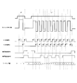
- an operation when data is recorded on a plurality of mark portions will be described with reference to FIGS.
- FIG. 5 is a diagram illustrating a write strategy when data is recorded on continuous mark portions having lengths of 2T, 3T, and 4T, respectively.
- the state of the power value change by the trigger signal depends on the state of each of the reordering signals 1 and 2 and their combination, and whether or not the current sequence is in the initial state. It may be configured to change.
- the sequence being in the initial state is intended to indicate a state after the end of recording of one mark portion and before the start of recording of the next mark portion.
- the interpretation mode of the order change signal is changed, and the power value at the start of the sequence and the state of the sequence pattern are changed according to the state of the order change signal.
- Control may be performed. More specifically, the power value that is a predetermined sequence value in the sequence pattern may be controlled by the first trigger signal at the start of the sequence, and the power value is determined by the subsequent trigger signal. In the above, it may be controlled to change the traveling direction of the sequence pattern.
- the sequence value is a change in the signal level of the trigger signals 1 and 2 when the signal levels of both the reordering signals 1 and 2 are at the low level. Is incremented by one. Further, when the signal levels of the order change signals 1 and 2 are both high (sequence values are 2, 4, and 8), the sequence is aborted.
- the sequence value at the start of the sequence is changed by the combination of the order change signals.
- the sequence for the mark portion is started, if the signal level of the order change signal 1 is at a low level and the signal level of the order change signal 2 is at a high level, the sequence pattern is traced backward.
- control is performed such that the power value changes (that is, the sequence value is subtracted by 1 by the change in the signal level of the trigger signals 1 to 3).
- FIG. 9 is a block diagram conceptually showing the structure of the first modification of the LD driver 10 in the present embodiment.
- the LD driver 10 includes a plurality of selectors (that is, the selector a14a and the selector b14b) instead of the selector 14, and a plurality of DACs (that is, the DACa16a and the DACb16b) instead of the DAC16. Is provided with an output selection section 18 for selecting one analog signal to be input to the output buffer 17 from among a plurality of analog signals output from.
- the power value that may be determined at the timing indicated by the next trigger signal by the operation of the sequencer 13 based on the sequence pattern and the control signal input from the order change signal processing unit 12. are determined by a plurality of selectors at least before the input of the actual trigger signal, and each power value is input to the DAC 15.
- the power value that can be determined is, for example, the power value set in the next order in the sequence pattern (that is, the power value that is one larger sequence value), and the sequence pattern progress by the order change signal.
- the sequence pattern sequence skipping or truncation operation by the above-described order change signal, etc. Any power value that can be determined based on the control by the pattern and the order change signal may be used.
- a plurality of selectors and DACs may be provided in addition to the above-described example, for example, three or more. At least a part of the power values that may be determined at a timing supported by the next trigger signal by a reordering signal such as forward feed, reverse feed, or truncation among a plurality of power values on the sequence pattern, or It is only necessary to determine all of them at least before the trigger signal is input and to perform signal processing in the DAC.
- a reordering signal such as forward feed, reverse feed, or truncation among a plurality of power values on the sequence pattern, or It is only necessary to determine all of them at least before the trigger signal is input and to perform signal processing in the DAC.
- a power value that may be determined in advance is output to the DAC 16 prior to the timing of the trigger signal change to perform signal processing. I can do it.
- signal processing in the DAC 16 such as a settling time suitably reduces a time lag that occurs from the timing of the trigger signal change to the timing of the actual laser light power change. I can do it. Therefore, the write strategy can be realized with higher accuracy.
- FIG. 10 is a block diagram conceptually showing the structure of the second modification example of the LD driver 10 in the present embodiment.
- the LD driver 10 includes a plurality of sequencers (that is, a sequencer a13a and a sequencer b13b) that define different sequence patterns. Further, a sequence selector 19 for selecting a sequencer to be applied from the plurality of sequencers a13a and b13b is further provided.
- a sequencer used in the sequence is selected based on the input of the order change signal in the initial state of the sequence.
- sequencers may be provided, for example, three or more in addition to the example described above.
- a plurality of sequencers that define a plurality of sequence patterns are provided.
- a suitable write strategy can be realized by appropriately selecting a sequencer corresponding to the write strategy at the start of the sequence.
- the processing of the order change signal in the sequence can be reduced according to the sequence pattern defined by the sequencer, and the processing amount during data recording can be reduced.
- FIG. 10 is a block diagram conceptually showing the basic structure of the information recording apparatus 1 in the example.
- the information recording apparatus 1 includes the optical pickup 52 including the above-described LD driver 10 and has at least a function of recording data on the mounted optical disc 100.
- the information recording apparatus 1 includes a disk drive 50 on which an optical disk 100 is actually loaded and data is recorded, and a host computer 30 such as a personal computer that controls data recording on the disk drive 50. And.
- the disk drive 50 includes an optical disk 100, a spindle motor 51, an optical pickup (PU) 52, a signal recording / reproducing unit 53, a memory 54, a CPU 55, an input / output control unit 56, and a bus 57.
- the host computer 30 includes an operation / display control unit, an operation button, a display panel, a CPU, a memory, an input / output control unit, a bus, and the like (not shown).
- the spindle motor 51 rotates and stops the optical disc 100, and operates when accessing the optical disc 100. More specifically, the spindle motor 51 is configured to rotate and stop the optical disc 100 at a predetermined speed while receiving spindle servo from a servo unit or the like (not shown).
- the optical pickup 52 includes, for example, a laser diode (LD) 40, the LD driver 10 described above, a photo detector (PD) 41, a collimator lens and an objective lens (not shown). It is prepared for. More specifically, at the time of data recording, the laser diode 40 irradiates the optical disc 100 with the laser beam LB while changing the power under the control of the LD driver 10. At this time, the LD driver 10 generates a drive signal, for example, for realizing the write strategy as described above, and drives the laser diode 40. As a result, a data pattern corresponding to the data is formed on the recording surface of the optical disc 100.
- a drive signal for example, for realizing the write strategy as described above
- the signal recording / reproducing unit 53 performs recording on the optical disc 100 by controlling the operations of the spindle motor 51 and the optical pickup 52 under the control of the CPU 54. More specifically, the signal recording / reproducing unit 53 is configured by, for example, a head amplifier. The head amplifier amplifies the output signal of the photodetector 41 provided in the optical pickup 52 (that is, a signal indicating the reflected light of the laser light and the read signal), and outputs the amplified signal. Further, the signal recording / reproducing unit 53 receives input of information and recording data related to the optical disc 100 from the host computer 30 described later, and outputs the information to the LD driver 10.
- the CPU 54 is connected to the signal recording / reproducing unit 53, the memory 55, and the input / output control unit 56 via the bus 57, and gives instructions to the signal recording / reproducing unit 53, the memory 55, and the input / output control unit 56, so 50 overall control.
- software or firmware for operating the CPU 54 is stored in the memory 55.
- the memory 55 is a buffer area for data used for recording operations and the like, and an area used as an intermediate buffer for conversion into data that can be used by the signal recording / reproducing unit 53.
- the memory 55 is used in general data processing in the disk drive 50. Is done.
- the memory 55 stores a ROM area in which a program (that is, firmware) for operating the information recording apparatus 1 is stored, and data used for a recording operation is temporarily stored, and is necessary for the operation of the firmware and the like.
- RAM area for storing various variables and the like.
- the input / output control unit 56 controls data input / output from the outside to the disk drive 50.
- a drive control command issued from an external host computer 30 connected to the disk drive 50 via an interface such as SCSI or ATAPI is transmitted to the CPU 54 via the input / output control unit 56.
- data used for the recording operation is exchanged with the host computer 30 via the input / output control unit 56.
- a specific example of the information recording apparatus 1 described above is a disk drive that records data under the control of a host computer 30 such as a known personal computer or workstation.
- a host computer 30 such as a known personal computer or workstation.
- it is a household device such as a recorder device that records video.
- the recorder device includes a disk drive unit and a control unit for controlling the disk drive unit, and the control unit corresponds to the host computer shown in FIG.
- the circuit configuration of the LD driver 10 can be simplified, and the amount of processing and the amount of heat radiation can be suitably reduced.
Landscapes
- Physics & Mathematics (AREA)
- Optics & Photonics (AREA)
- Optical Recording Or Reproduction (AREA)
- Optical Head (AREA)
- Semiconductor Lasers (AREA)
Abstract
レーザ駆動装置(10)は、レーザ光を照射する照射手段(40)と、あらかじめ設定される複数の設定値及び設定値間の遷移の順序を保持する記憶手段(15)と、複数の設定値のうち、一の設定値から他の設定値へと遷移するタイミングを示すトリガ信号を取得するトリガ手段(11)と、設定値間の遷移の順序の進行方向を指示する順序変更信号を取得する順序変更手段(12)と、トリガ信号の信号レベルの変化に応じたタイミングにおいて、設定値間の遷移の順序に基づいて、出力される設定値を決定する出力決定手段(13)と、決定された設定値をアナログ信号へと変換し、照射手段へと出力するDA変換回路(16)とを備える。
Description
本発明は、光ディスクなどの情報記録媒体に対しレーザ光を照射することで情報の記録を行う情報記録装置に備えられ、レーザ光の出力を変動させつつ照射を行うよう制御するレーザ駆動装置、該レーザ駆動装置に備えられる信号処理回路及び該レーザ駆動装置が備えられる情報記録装置の技術分野に属する。
例えば光ディスクなどの情報記録媒体においては、レーザダイオードから光ディスクに向けてレーザ光が照射されることで、該光ディスク上に記録マークないしは記録ピットが形成される。これにより、光ディスクにデータが記録される。レーザダイオードには、該レーザダイオードが動作するために必要な動作電圧が印加されるように、電源から一定の電源電圧が供給されている。そして、レーザダイオードから照射されるレーザ光は、トランジスタ等を含むレーザドライバ回路の動作により、その波形やパワーが制御される。特に、多値レベル化及びパルス分割されたレーザ光の波形やパワーのパターンをライトストラテジと言う。
このような、ライトストラテジを実現するためには、高速且つ連続的に変化するパルス化されたレーザ光の波形及びパワーを制御することが必要であり、従来、幾つかの手法が用いられている。
例えば、レーザダイオードに対し、複数通りのパワーのレーザ光を照射させるための電流を供給する複数の電流源を備え、その電流源にそれぞれ対応するコントロール入力により電流源からの電流の供給を直接切り替えることでレーザダイオードへの供給電流を変化させ、レーザダイオードのレーザ光のパワーを変化させる、所謂コンベンショナル型と呼ばれる手法がある。
また、特許文献1には、レーザ駆動装置に対して、マーク長を指示するNRZI(Non Return to Zero Inversion)信号と、該NRZI信号の基準となるクロック信号を伝送し、レーザ駆動装置の内部でクロックを逓倍することで十分短い間隔の内部クロックを生成し、これをカウントすることでストラテジパターンを再現する、ストラテジブロックを内蔵する構成が開示されている。
しかしながら、上述したコンベンショナル型の方法によれば、幅の細いパルス信号が必要とされるライトストラテジにおいては、電流源からの電流の供給を切り替えるための制御信号も幅の細いパルスである必要があるため、信号伝送が比較的困難になるという技術的問題がある。また、レーザ光のパワーを変化させるために、例えば一の電流源からの電流の供給をオフにするとともに、他の電流源からの電流の供給を開始するなど、同タイミングで複数の電流源からの電流の供給を切り替えることが求められることがある。このような場合、複数の電流源への制御を同期させる必要があるため、信号伝送は厳密にタイミング管理される必要がある。例えば、複数の電流源への制御に時間的なズレが生じる場合、レーザ光においてパワーの超過や欠落などが生じるという技術的な問題が指摘されている。
他方で、ストラテジブロック内蔵タイプは、幅の細いパルス信号を生成する構成と、該パルス信号に基づいて電流を変化させる構成とが、ともにレーザ駆動装置内部にあるため、タイミングの管理が比較的容易に行うことが出来るという利点がある。
しかしながら、十分に幅の細いパルス信号を生成するためには、外部クロック信号に基づいて、逓倍処理などによって生成される内部クロック信号の周波数が高くなり(つまり、高速化し)、また、高速のクロック信号に従って内部パルス信号を生成する回路も大規模となってしまう。このため、レーザ駆動装置全体での処理量が増加することとなり、結果として発熱量の増大、チップ面積の増大などに繋がってしまう。
本発明は、例えば上述した従来の問題点に鑑みなされたものであり、例えば制御信号におけるパルス幅を所定の長さ以上に保ちつつ、比較的小規模の回路構成によって、レーザ光の多様なパワー変化に対応したライトストラテジを実現し得るレーザ駆動装置を提供することを課題とする。
上記課題を解決するために、本発明のレーザ駆動装置は、設定値に応じたパワーのレーザ光を照射する照射手段と、あらかじめ設定される複数の前記設定値を保持する記憶手段と、前記設定値間の遷移の順序を規定する順序規定手段と、複数の前記設定値のうち、一の前記設定値から他の前記設定値へと遷移するタイミングを示すトリガ信号を取得するトリガ手段と、前記設定値間の遷移の順序の進行方向を指示する順序変更信号を取得する順序変更手段と、前記トリガ信号の信号レベルの変化に応じたタイミングにおいて、前記順序変更信号の信号レベルに応じて設定される前記設定値間の遷移の順序に基づいて、出力される前記設定値を決定する出力決定手段と、決定された前記設定値をアナログ信号へと変換し、前記照射手段へと出力するDA変換回路とを備える。
上記課題を解決するために、本発明の信号処理回路は、上述のレーザ駆動装置に接続され、前記トリガ手段に対して前記トリガ信号を供給するトリガ信号供給手段と、前記順序変更手段に対して前記順序変更信号を供給する。
上記課題を解決するために、本発明の情報記録装置は、上述のレーザ駆動装置を備える。
本発明の作用及び他の利得は次に説明する実施の形態から明らかにされよう。
1 情報記録装置、
10 LDドライバ、
11 トリガ信号判定部、
12 順序変更信号処理部、
13 シーケンサ、
14 セレクタ、
15 パワー値保持部、
16 DAC、
17 出力バッファ、
18 出力選択部、
20 信号処理回路、
21 トリガ信号生成部、
22 順序変更信号生成部、
30 ホストコンピュータ、
40 レーザダイオード
10 LDドライバ、
11 トリガ信号判定部、
12 順序変更信号処理部、
13 シーケンサ、
14 セレクタ、
15 パワー値保持部、
16 DAC、
17 出力バッファ、
18 出力選択部、
20 信号処理回路、
21 トリガ信号生成部、
22 順序変更信号生成部、
30 ホストコンピュータ、
40 レーザダイオード
本発明のレーザ駆動装置に係る実施形態は、設定値に応じたパワーのレーザ光を照射する照射手段と、あらかじめ設定される複数の前記設定値を保持する記憶手段と、前記設定値間の遷移の順序を規定する順序規定手段と、複数の前記設定値のうち、一の前記設定値から他の前記設定値へと遷移するタイミングを示すトリガ信号を取得するトリガ手段と、前記設定値間の遷移の順序の進行方向を指示する順序変更信号を取得する順序変更手段と、前記トリガ信号の信号レベルの変化に応じたタイミングにおいて、前記順序変更信号の信号レベルに応じて設定される前記設定値間の遷移の順序に基づいて、出力される前記設定値を決定する出力決定手段と、決定された前記設定値をアナログ信号へと変換し、前記照射手段へと出力するDA変換回路とを備える。
本発明のレーザ駆動装置に係る実施形態によれば、順序規定手段によって、記憶手段にあらかじめ保持される複数のレーザ光パワーの設定値の一の値から他の値へと遷移する際の設定値間の遷移の順序が規定される。そして、出力決定手段によって、トリガ手段が取得するトリガ信号により示されるタイミング(より具体的には、トリガ信号の信号レベルの変化に応じたタイミング)において、一の設定値から他の設定値へと、遷移の順序に従ってレーザ光のパワーの設定値が変更される。変更されたレーザ光のパワーの設定値は、DA変換回路を通じて照射手段へと入力され、該設定値に応じたパワーでレーザ光の照射が実施される。
ここに、レーザ光のパワーの設定値とは、照射手段に複数のパワーのレーザ光を照射させるために、複数のパワー夫々に対応してあらかじめ設定され、記憶手段に格納される設定値である。このような複数の設定値のうち、後述する設定値間の遷移の順序に基づいて出力される設定値が出力決定手段により決定され(言い換えれば、読み取られ)、DA変換回路へと出力される。
また、設定値間の遷移の順序とは、前述した複数の設定値のうち、一の設定値から他の設定値へと遷移する際の遷移の順序を示す趣旨であり、好適には、順序規定手段によって複数の設定値の夫々を網羅するように一意に規定される。このとき、設定値間の遷移の順序においては、同一の設定値が重複して異なる順番で設定されていても良い。例えば、A、B、Cという3つの相異なる設定値が設定されている場合、設定値間の遷移の順序として、A→B→C→AやC→B→A→Cなどの順序に加えて、A→B→A→C→Aなどのように、一連の流れの中で同一の設定値が複数回登場する順序もまた規定されて良い。
本発明のレーザ駆動装置に係る実施形態によれば、トリガ手段により取得されるトリガ信号の信号レベルが変化するたびに、上述の設定値間の遷移の順序に従って、出力される設定値が遷移する。言い換えれば、トリガ信号の信号レベルが変化するたびに、新しいレーザ光のパワーを示す設定値がDA変換回路へと出力され、結果として照射されるレーザ光のパワーが遷移する。
ここに、トリガ信号は、レーザ光のパワーの遷移(つまりは、設定値の遷移)を実行するタイミングを示す、例えば、2値的な信号レベルを有するパルス状の信号である。このようなトリガ信号の信号波形を監視することによって、例えば、該トリガ信号の立ち上がりや立ち下がりのタイミングに応じて、設定値の遷移が実行される。従って、予め設定される設定値と設定値間の遷移の順序を調整することで、所望のライトストラテジを実現することが出来る。
また、このようなトリガ信号によれば、例えばパルス状である該トリガ信号の信号レベルの変化に応じてレーザ光のパワーを所定の遷移の順序に従って遷移させられる。また、或る一つのタイミングにおいて、単一のトリガ信号による遷移のみが行われるよう設定することで、例えば、コンベンショナル型のレーザダイオードドライバに見られるような、複数のコントロール入力信号間のスキューなどに起因するパワーの過剰出力や欠落などが発生する技術的問題を好適に解消することが出来る。また、順序規定手段の動作によれば、設定値間の遷移の順序を調整することで、多様なライトストラテジに対応する設定値の遷移の順序をあらかじめ規定しておくことが出来、例えば、ストラテジブロックを内蔵する従来型のLDDに比較して、より小規模なロジックでのライトストラテジを実現できる。
また、本発明のレーザ駆動装置に係る実施形態によれば、特に、順序変更手段により取得される順序変更信号の状態(例えば、信号レベル)に基づいて、設定値間の遷移の順序が変更される。ここに、順序変更信号は、典型的には、二値的な信号レベルを有する信号であって、典型的には、上述のトリガ信号に比較して長いスパンでの状態の変化が許容される。このような順序変更信号による制御として、例えば、設定値間の遷移の順序の進行方向を順送りまたは逆送りの一方に指定したり、遷移の順序において次に設定される一つあるいは複数の設定値をスキップしたり、所定の順番へとジャンプするような制御が実施される。更に、後に詳述するように、一連の設定値の遷移を打ち切り、所定の設定値を設定するような所謂シーケンスの打ち切り制御が実施されても良い。このような順序変更信号による設定値の遷移の順序の制御を行うことで、記憶手段に格納される設定値の数をより少なく抑えた上で、多様なライトストラテジを実現することが出来るため、記憶手段の、ひいては当該レーザ駆動装置の回路構成をより小規模とすることが出来る。
更に、例えば、該順序変更信号の信号レベルが所定レベルである期間に、トリガ信号の信号レベルが変化した場合に、設定値間の遷移の順序を逆送りとして扱うように設定すれば、順序変更信号の信号レベルの変化の態様をトリガ信号の信号レベルの変化の態様ほど厳密に設定しなくとも上述の効果を享受することが出来る。例えば、設定値間の遷移の順序を逆送りに変更されるタイミングを示すトリガ信号の信号レベルが変化するタイミング以前であって、一つ前のトリガ信号(つまり、順送りで設定値の遷移を行うための信号)の信号レベルが変化するタイミング以降の任意のタイミングにおいて順序変更信号の信号レベルの制御を実施することで、好適に所望のトリガ信号における遷移の順序を変更することが出来る。
また、順序変更手段は、例えば、複数の順序変更信号を取得出来るよう構成されていても良く、このとき、複数の順序変更信号の夫々の信号レベルなどの状態の組み合わせにより、上述した各制御が実施されるよう構成されても良い。このように構成すれば、より複雑な遷移の順序変更制御を実現することが出来、より少ない設定値より構成される遷移の順序を用いて、より多様なライトストラテジを実現することが出来る。
以上、説明したように、本発明のレーザ駆動装置に係る実施形態によれば、設定値の遷移のタイミングを制御するトリガ手段と、設定値間の遷移の順序の変更を制御する順序変更手段の動作によって、あらかじめ設定される比較的少ない数の設定値から構成される遷移の順序を用いて、比較的多くの設定値間の遷移を実現出来る。従って、比較的小規模なロジック構成であっても、多様なライトストラテジを実現することが出来る。
本発明のレーザ駆動装置に係る実施形態の一の態様は、前記出力決定手段は、前記トリガ信号の信号レベルが変化するタイミングのみにおいて、前記設定値間の遷移の順序に基づいて出力される前記設定値を決定する。
この態様によれば、トリガ信号の信号レベルが変化するタイミング(例えば、トリガ信号が立ち上がるタイミングや、トリガ信号が立ち下がるタイミング等)のみにおいて、上述した設定値の遷移が実施される。言い換えれば、例えば、順序変更信号の状態の変更などによっては、設定値の遷移は実施されない。
このように構成すれば、厳密なタイミングの管理が要求されるライトストラテジを実現するためには、典型的には、トリガ信号の状態の変更のタイミングのみを厳密に管理すれば良く、従って、その他の、例えば順序変更信号の状態の変更などのタイミング管理の厳密さを比較的緩和することが出来る。このことから、トリガ手段及びトリガ信号の伝送系に比較して、その他の例えば順序変更信号の伝送系が低速な回路構成であっても、所望のライトストラテジを実現出来る。
本発明のレーザ駆動装置に係る実施形態の他の態様は、前記順序変更信号は、(i)前記設定値間の遷移の順序の進行方向を、順送り及び逆送りの一方に指示する信号、及び(ii)一時的に所定の前記設定値を適用させるとともに、次の一連のレーザ光の照射を所定の前記設定値において開始させる、遷移の打ち切りを指示する信号を含む。
この態様によれば、順序変更手段が取得する順序変更信号を用いた制御により、設定値の遷移の順序を順送り、または逆送りに指定することが出来る。また、例えば、順序変更信号の状態の変化によって、遷移の順序の進行を順送り及び逆送りのいずれにするかを制御するよう構成すれば、一連の遷移の順序における特定の設定値の遷移の繰返し動作などを比較的簡単に指示することが出来る。
上述した特定の設定値の遷移の繰返し動作の例として、典型的には、所定の間隔でパルス状に低パワー状態と高パワー状態とを繰り返すマルチパルス波形のライトストラテジなどがある。このとき、本態様によれば、例えば、低パワー設定値A→高パワー設定値B→低パワー設定値A、というように設定される遷移の順序において、設定値がA→B→A→B→Aの順序で遷移するよう順序変更信号を設定することで、マルチパルス波形のライトストラテジが実現出来る。更に、同じ波形を構成する場合に、例えば、低パワー設定値Aと同一設定値である低パワー設定値Cを利用することによって、設定値がA→B→C→B→Aの順序で遷移するよう順序変更信号を設定することで、順序変更手段の状態変化の間隔を広げつつ、パワー設定値を繰り返し利用することが出来る。このため、マルチパルス波形の構成に必要なパワーの設定値を一時保存するための(言い換えれば、低パワー設定値から高パワー設定値へ切り替えるための)レジスタセットを減少させることが出来る。従って、比較的小規模な回路構成で、所望のライトストラテジを実現出来る。
更に、順序変更信号は、設定値の遷移の順序を所定の設定値までスキップさせるような制御を行うよう構成されていても良い。このように構成することで、特定のマーク長にのみ、あるパワー設定値を挿入することができる。また、スキップする所定の設定値を、マーク部の開始以前の状態とすることで、一連のレーザ光の照射を終了し、設定値を、通常の遷移の順序に従うことなく、所定の値に決定する(言い換えれば、所定の値にまで遷移の順序をスキップする)、所謂打ち切り動作を実現することが出来る。
ここに、一連のレーザ光の照射とは、例えば、記録媒体に記録される信号に応じて規定される各データマーク部を形成するためのレーザ光の照射を示す趣旨であって、シーケンスとも称される(以下、シーケンスと記載する)。典型的に、記録マークにより規定されるマーク部外の領域(つまり、マーク部とマーク部との間)では、照射手段は、所定のパワーでレーザ光を照射するよう構成されている。
従って、このように構成すれば、異なるマーク長を有するマーク部の夫々に対して、任意の位置でシーケンスを終了させることで、比較的小規模な回路構成で、所望のライトストラテジを実現出来る。
また、打ち切り前の設定値を保持しておき、次回のシーケンス開始時に、保持されている設定値から設定値の遷移を実施するよう構成されていても良い。これによっても、小規模な回路構成でより多様なライトストラテジを実現することが出来る。
上述の如く順序変更信号が(i)遷移の順序の進行方向を、順送り及び逆送りの一方に指示する信号、及び(ii)遷移の打ち切りを指示する信号を含むレーザ駆動装置の態様では、前記出力決定手段は、前記順序変更信号が所定の信号レベルとなった後、予め設定される所定のタイミングにおいて前記順序変更信号を適用するように構成してもよい。
このように構成すれば、例えば、順序変更信号がonとなった(具体的には、例えば順序変更信号の信号レベルがハイレベルとなった)後に最初に信号レベルが変化するトリガ信号の信号レベルが変化するタイミングにおいて、順序変更信号による制御を実施する代わりに、順序変更信号がonとなってから所定のタイミングの後において順序変更信号による制御が実施される。例えば、順序変更信号によって、設定値の遷移の順序変更が指示されている状態でトリガ信号の信号レベルが変化した後、実際には、2つ目のトリガ信号の信号レベルが変化するタイミングにおいて、設定値の遷移の順序が変更されるよう制御される。
ライトストラテジのパターンによっては、例えば、シーケンスの終了間際に比較的高速且つ連続的にパワーの変化が必要となる場合がある。このような場合に、最後のパワー変化を指定するトリガ信号に対してシーケンスの打ち切りを指示する順序変更信号を入力するためには、順序変更信号にも厳密なタイミング管理が必要となる。このため、高速且つ厳密なタイミング管理のされた順序変更手段が必要となるため、回路構成が複雑となったり、伝送路の構成が比較的困難となってしまうという技術的な問題が生じる。
他方で、一般的に、このような立て続けにパワー変化が要求される領域は限られており、その前の部分にはいずれのマーク長に対してもパワー変化の間隔が広い部分が存在することが普通である。従って、このようなパワー変化の間隔の広い部分において、タイミングを指定しつつシーケンスの打ち切りを指定する順序変更信号を用いれば、順序変更手段における厳密なタイミング管理を行う必要がなくなる。このような順序変更信号による制御のタイミング指定は、例えば、所定の指示(例えば、シーケンスの打ち切りなど)を示す順序変更信号に対してのみ行われるよう構成されていても良い。その他、任意の順序変更信号に対してのみタイミングの指定を行うよう構成しても良く、他方で、全ての順序変更信号に対してタイミングの指定を行っても良い。
更に、シーケンスの打ち切りを示す順序変更信号が、幾つか後のトリガ信号の信号レベルが変化するタイミングにおいて実施されるよう入力された場合、シーケンスの打ち切りが認識されたトリガ信号の信号レベル変化以降は、次のシーケンス開始時まで順序変更信号の状態を無視するよう構成しても良い。このように構成すれば、打ち切り指示後の順序変更信号の状態が、次のシーケンスに影響することを好適に抑制することが出来る。この結果、パワー変化の間隔が広い部分で指示された打ち切りの指示に対し、その後の比較的高速かつ連続的なパワー変化の時点で、順序変更信号がいかなる状態であっても現在のシーケンスは終了し、次のシーケンスに影響を与えないため、順序変更信号が終了状態から初期状態へと変化する時間に余裕ができ、よって比較的低速の順序変更信号を使用することができるのである。
本発明のレーザ駆動装置に係る実施形態の他の態様は、前記出力決定手段は、一連のレーザ光照射の開始時において、前記順序変更信号の信号レベルに応じて、前記設定値間の遷移の順序を変更する。
この態様によれば、シーケンスの開始時の順序変更信号の状態に基づいて、シーケンス開始時に決定される設定値や、次に決定される設定値の遷移の順序が変更される。
典型的に、シーケンスが初期状態にある場合、シーケンスの開始時の最初のトリガ信号の変化のタイミングにおいては、設定値がとり得る値は、設定値の遷移の順序における最初の設定値である。また、シーケンス開始後の二つ目のトリガ信号の変化のタイミングにおいては、設定値がとり得る値は、設定値の遷移の順序における次の設定値である。つまり、シーケンスが初期状態にある場合、順序変更信号による設定値の遷移の順序の変更制御の必要がない。
そこで、このような態様によれば、シーケンスの開始時における順序変更信号の解釈を変更することで、例えば、シーケンス開始時の最初の設定値や、続く設定値の遷移の順序をあらかじめ指定することが出来る。より具体的には、例えば、設定値の遷移の順序をスキップさせるなどによって、所望の設定値からシーケンスを開始するよう変更することが出来る。
また、シーケンス開始から、シーケンスの終了までの設定値の遷移の順序をすべて変更するよう制御しても良く、他方で、シーケンスの開始時にのみ遷移の順序の態様の変更を適用させても良い。このように構成すれば、小規模な回路構成でより多様なライトストラテジを実現することが出来る。
本発明のレーザ駆動装置に係る実施形態の他の態様は、前記記憶手段は、複数の前記設定値間の遷移の順序を保持し、前記出力決定手段は、前記トリガ信号の信号レベルの変化に応じたタイミングにおいて、複数の前記設定値間の遷移の順序のうちのいずれか一つに基づいて出力される前記設定値を決定する。
この態様によれば、あらかじめ設定される複数の設定値間の遷移の順序を用いることで、所望のライトストラテジを実現出来る。一般的に、データの記録を行う情報記録装置においては、実際に使用されるライトストラテジの波形は、一つのシーケンスにおけるパワーの遷移の様子によって幾つかのタイプに分類することが出来る。このような波形の例として、例えば、マルチパルス型、L型、キャッスル型のライトストラテジが知られている。また、各タイプの波形においては、データが記録されるマーク部のマーク長に応じて、波形の概形が異なる態様が存在する。例えばキャッスル型のライトストラテジであっても、比較的短マークなマーク部に対しては、モノパルスで記録を行い、長マーク部に対しては、所謂キャッスル型で記録を行うものなどがある。
しかしながら、このような概形の変化を考慮したとしても、実際のデータの記録に用いられるライトストラテジの波形のタイプはそれほど多くはない。そこで、予想されるパワーの遷移の様子に対応した複数の設定値間の遷移の順序(以降、シーケンスパターンと記載する)をあらかじめ記憶手段に格納しておき、シーケンスの開始時に、用いられるシーケンスパターンを決定することで、比較的簡単に(例えば、トリガ信号の信号レベルの変化に応じて順次設定値を遷移させるだけで)好適なライトストラテジの実現が出来る。
このようなシーケンスパターンは、一つのシーケンスの開始から終了に対して適用されるよう、例えば各マーク長に合わせて複数種類用意されていても良い。このように構成すれば、一つのマーク部に対し、そのマーク長に対応したシーケンスパターンでの記録が行われた後、自動的にシーケンスが終了される(つまり、所定のパワーでレーザ光を照射する設定値が決定される)。
また、シーケンスパターンと順序変更信号による制御とを組み合わせることで、比較的少数のシーケンスパターンを用意しているだけでも、順序変更信号による順序変更制御によって多様なライトストラテジを実現することが出来る。例えば、マルチパルス型のライトストラテジなどに対して、所定の設定値の遷移を順序変更制御によって繰り返させることで、マーク長の夫々異なるライトストラテジにも対応することが出来る。逆に、シーケンスパターンの最中に上述した打ち切り動作などによってシーケンスを終了させることでも、多様なライトストラテジの実現につながる。
尚、シーケンスパターンの選択は、例えば、設定値の遷移の順序変更の一環として、順序変更手段により取得される順序変更信号に基づいて行われても良く、また、その他何らかの制御のもと行われても良い。
また、シーケンスパターンはあらかじめ固定された設定値の選択を行うよう構成されていても良く、また、所定のトリガ信号の信号レベルが変化する順に、決定する設定値が選択可能であるよう構成されていても良い。
本発明のレーザ駆動装置に係る実施形態の他の態様は、複数の前記DA変換回路と、複数の前記DA変換回路から夫々出力される複数の前記アナログ信号のうち、前記照射手段へと実際に出力される前記アナログ信号を選択する出力選択手段を更に備え、前記出力決定手段は、複数の前記DA変換回路に対して、次の前記トリガ信号が変化するタイミングにおいて決定される可能性のある前記設定値を入力するとともに、前記出力選択手段は、次の前記トリガ信号の信号レベルが変化するタイミングにおいて、前記設定値間の遷移の順序に基づいて、前記照射手段へと実際に出力される前記アナログ信号を選択する。
この態様によれば、複数備えられるDA変換回路の夫々に対し、設定値間の遷移の順序に基づく次回のトリガ信号の信号レベルが変化するタイミングにおいて決定される可能性のある設定値があらかじめ入力される。このように構成すれば、比較的スルーレートが低いDA変換回路を用いたとしても、DA変換回路における信号処理に要する時間(例えば、セトリングタイム)によってトリガ信号の信号レベルが変化してから、実際に設定値が適用されるまでの間に生じる時間的なズレを好適に軽減することが出来る。
尚、設定値間の遷移の順序は、順序変更信号の入力に従って変動する可能性がある。そこで、本態様によれば、複数のDA変換回路の夫々に対して、次に決定される可能性のある設定値をあらかじめ入力しておき、夫々のDA変換回路における信号処理を進めておくことが出来る。このように構成すれば、その後の順序変更信号やトリガ信号の状態に基づいて、実際に照射手段へと出力される設定値を示すアナログ信号を選択して出力することで、好適にトリガ信号の取得から、実際に設定値が適用されるまでの時間的なズレを抑制することが出来る。上述のように、順序変更信号は、該順序変更信号が実際に適用されるトリガ信号に対して十分先立って取得されるため、順序変更信号の状態を確認した後であっても、実際に出力されるアナログ信号を選択することが出来る。
本発明のレーザ駆動装置に係る実施形態の他の態様は、前記トリガ手段は、複数の前記トリガ信号を取得し、複数の前記トリガ信号のうち、少なくとも一つの前記トリガ信号に基づいて、前記設定値が遷移するタイミングが示される。
この態様によれば、複数のトリガ信号の信号レベルが変化するタイミングの夫々において、設定値の遷移が実施される。より具体的には、複数の信号回路により出力される複数のトリガ信号が、夫々対応する信号線により伝送される。そして、夫々のトリガ信号におけるエッジ抽出などの信号レベルの判定などによって決定されたタイミングにおいて、設定値の決定が実施される。
このように構成すれば、一つのトリガ手段がトリガ信号を取得する場合に比較して、ごく短い時間で設定値を複数回遷移するような場合において、順序的に隣接する設定値の遷移タイミングを相異なるトリガ信号によって示すことができるため、各トリガ信号の信号レベルの変化の態様の厳密さを緩和することが出来る。具体的には、例えば、パルス幅0.2Tという間隔でのトリガ信号の出力が要求されるライトストラテジにおいても、一のトリガ信号の信号レベルの変化に続いて、0.2T後のタイミングにおいて他のトリガ信号の信号レベルを変化させることで好適に対応出来る。更に、この場合、個々のトリガ信号のパルス幅を、例えば0.2T以下に抑える必要もない。従って、比較的低速の回路を用いても、所望のライトストラテジを実現することが出来る。
本発明のレーザ駆動装置に係る実施形態の他の態様は、前記トリガ手段は、前記トリガ信号に加えて、前記トリガ信号の判定に用いられるスライスレベル信号をも取得する。
この態様によれば、例えば、パルス状の信号であるトリガ信号とともに、該トリガ信号の信号レベルの判定のための閾値を示すスライスレベル信号が取得される。より具体的には、トリガ信号を伝送する信号線に加えて、スライスレベル信号を伝送するための信号線が設けられ、例えば、トリガ信号と同期したタイミングなどでトリガ信号判定のためのスライスレベル信号が伝送される。
一般的に、シングルエンドのパルス信号の場合、信号レベルの時間的な変化にはある程度の傾きが存在するため、信号レベルに変化が生じたタイミングから、信号レベルがスライスレベルを超えたと判定されるまでには多少の時間的なズレが生じる。このとき、スライスレベルが信号レベルに対してどのような比率にあるかによって、このような時間的なズレは変化するが、例えば、スライスレベルが信号レベルの1/2より増加した場合、パルス信号の立ち上がり時には、変化が生じたタイミングからスライスレベルを上回るまでの時間的なズレは増大する一方で、パルス信号の立ち下がり時には、変化が生じたタイミングからスライスレベルを下回るまでの時間的なズレは減少する。従って、信号レベルの判定を波形の立ち上がり時と立ち下がり時の両方で行う場合、上述したとおり立ち上がり時と立ち下がり時とで逆方向に生じる時間的なズレが加算されるため、パルス幅によってレーザ光のパワーの設定値の遷移のタイミングを指定するシングルエンドの伝送方法においては、ライトストラテジの精度が低下してしまうという技術的な問題がある。この現象はパルス信号の送り側と受け手側においてスライスすべきレベルが異なってしまうことが原因となる。
本態様によれば、トリガ信号とともに、信号の送り側のスライスレベル信号が伝送される。そして、トリガ信号の信号レベルがスライスレベルの信号レベルを上回る、または下回るタイミング(つまり、トリガ信号とスライスレベル信号の夫々の波形が交差するタイミング)において、設定値の決定処理が実施される。このとき、トリガ信号のレベルと、スライスレベルのいずれも信号の送り手側で決定されるため、送り手側と受け手側に電源電圧やグランドレベルの差異があったとしても、送り手側の意図するレベルでのスライスが可能となり、上述したトリガ信号の時間的なズレに起因するパルス幅の変動を抑制することが出来る。結果、好適に所望のライトストラテジを実現することが出来る。
また、上述したように複数のトリガ信号を用いる場合であっても、単一の送り手から送られるトリガ信号のレベルは同一であるため、一本の信号線だけを用いて一通りのスライスレベル信号の伝送を行えば、上述した効果を享受出来る。このため、後に詳述する差動伝送の態様と比較して、より少ない信号線を用いる構成で、上述したトリガ信号の時間的なズレに起因するパルス幅の変動を抑制することが出来る。結果、好適に所望のライトストラテジを実現することが出来る。
本発明のレーザ駆動装置に係る実施形態の他の態様は、前記出力決定手段は、前記トリガ信号の波形における立ち上がりエッジ及び立ち下がりエッジのいずれか一方がスライスレベルを超えるタイミングにおいて、出力される前記設定値を決定する。
この態様によれば、例えば、パルス状の信号であるトリガ信号において、波形の立ち上がりの際の信号レベルがスライスレベルを超える(つまり、上回る)タイミングと、波形の立ち下がりの際の信号レベルがスライスレベルを超える(つまり、下回る)タイミングとのいずれか一方のタイミングにおいて、出力される設定値が決定される。
従来、比較的高速で遷移する信号の伝送には、例えば、LVDS(Low voltage differential signaling)などの差動信号が用いられてきた。より具体的には、LVDSなどの作動信号においては、互いに逆位相の信号を伝送する2本の信号線を用い、一方の信号線における信号レベルが、他方の信号線の信号レベルを上回る場合に「1」、下回る場合に「0」となるよう設定される。このような差動信号を用いれば、上述したシングルエンド信号における信号検出の時間的なズレに起因するパルス幅の変動を排除することが出来る。他方で、信号線の数が2倍に増えることと、比較的短いパルス幅のトリガ信号を伝送するためには、夫々の信号線において高速な応答をすることなどが必要となる。
そこで、本態様のように構成することで、上述した時間的なズレが一方向のみに現れることから、シングルエンドの伝送方法を用いつつも、パルス幅の変動を好適に排除することが出来る。また、2本の信号線を用いる場合、差動伝送においては、パルス信号の伝送のために、該パルス信号そのものを伝送する必要があるため、比較的短いパルス信号の伝送には、高速な応答が必要とされる。他方で、差動伝送の態様を採らず、2本の信号線を用いる場合(つまり、上述の、複数のトリガ手段を備える態様を採る場合)、本態様のように信号の判定タイミングを設定することで、パルス信号の開始と終了を夫々独立した信号線における信号の立ち上がり、または立ち下がりによって表すことが出来るため、信号入力のタイミングにさえ注意していれば、個々の信号のパルス幅が受ける制限が比較的に緩和される。
本発明の信号処理回路に係る実施形態は、上述した本発明のレーザ駆動装置に係る実施形態(但し、その各種態様を含む)に接続され、前記トリガ手段に対して前記トリガ信号を供給するトリガ信号供給手段と、前記順序変更手段に対して前記順序変更信号を供給する。
本発明の信号処理回路に係る実施形態によれば、上述したトリガ信号及び順序変更信号を好適に供給することが出来る。このように構成すれば、好適に上述したレーザ駆動装置の各効果を享受することが出来る。
本発明の情報記録装置に係る実施形態は、上述した本亜発明のレーザ駆動装置に係る実施形態(但し、その各種態様を含む)を備える。
本発明の情報記録装置に係る実施形態によれば、上述したレーザ駆動装置の各効果を享受しながら、例えば光ディスクなどの情報記録媒体に対し、好適に情報の記録を行うことが出来る。
以上説明したように、本実施形態に係るレーザ駆動装置によれば、照射手段と、記憶手段と、順序規定手段と、トリガ手段と、順序変更手段と、出力決定手段と、DA変換回路とを備える。本実施形態に係る信号処理回路によれば、トリガ信号供給手段と、順序変更信号供給手段とを備える。本実施形態に係る情報記録装置は、本実施形態に係るレーザ駆動装置を備える。従って、制御信号におけるパルス幅を所定の長さ以上に保ちつつ、比較的小規模の回路構成によって、レーザ光の多様なパワー変化に対応したライトストラテジを実現することができる。
以下、本発明を実施するための最良の形態について図面を参照して説明する。
(1)基本構成例
始めに、図1を参照して、本発明の実施例に係るLDドライバ(Laser Diode Driver)10の基本的な構成について説明しながら、該LDドライバ10の基本的な動作について説明する。ここに、図1は、本実施例におけるレーザ駆動装置の一例であるLDドライバ10の構成を概念的に表すブロック図である。尚、LDドライバ10は、典型的には、光ピックアップ52(図10参照)の内部に設けられ、同じく光ピックアップ52内に設けられるレーザダイオード(LD)40に接続される。このため、LDドライバ10は後に詳述するように、ライトストラテジに応じてLD40におけるレーザ光の照射パワーやタイミングを制御することが出来る。また、LDドライバ10は、典型的には、光ピックアップ52が設けられる本体基板上に備えられる信号処理回路20と接続されている。このため、後に詳述するように、外部クロックなどを利用したトリガ信号や順序変更信号などの入力を受けることが出来る。 図1に示されるように、LDドライバ10は、外部からのトリガ信号の入力を受けて該トリガ信号の処理を行うトリガ信号処理部11と、外部からの順序変更信号の入力を受けて該順序変更信号の処理を行う順序変更信号処理部12と、トリガ信号及び順序変更信号に基づいて、レーザダイオード40において照射されるレーザ光LBのパワー値の変化を制御するためのシーケンサ13と、シーケンサ13による制御のもと、選択されるレーザ光LBのパワー値を選択するセレクタ14と、パワー値に対応し、複数のパワー値の夫々を設定するための設定値が格納されるパワー値保持部15と、セレクタ14からのパワー値の入力を受け、該パワー値をレーザダイオード40に出力するためのDAC(Digital Analog Convertor)16と、出力バッファ17とを備えて構成される。
始めに、図1を参照して、本発明の実施例に係るLDドライバ(Laser Diode Driver)10の基本的な構成について説明しながら、該LDドライバ10の基本的な動作について説明する。ここに、図1は、本実施例におけるレーザ駆動装置の一例であるLDドライバ10の構成を概念的に表すブロック図である。尚、LDドライバ10は、典型的には、光ピックアップ52(図10参照)の内部に設けられ、同じく光ピックアップ52内に設けられるレーザダイオード(LD)40に接続される。このため、LDドライバ10は後に詳述するように、ライトストラテジに応じてLD40におけるレーザ光の照射パワーやタイミングを制御することが出来る。また、LDドライバ10は、典型的には、光ピックアップ52が設けられる本体基板上に備えられる信号処理回路20と接続されている。このため、後に詳述するように、外部クロックなどを利用したトリガ信号や順序変更信号などの入力を受けることが出来る。 図1に示されるように、LDドライバ10は、外部からのトリガ信号の入力を受けて該トリガ信号の処理を行うトリガ信号処理部11と、外部からの順序変更信号の入力を受けて該順序変更信号の処理を行う順序変更信号処理部12と、トリガ信号及び順序変更信号に基づいて、レーザダイオード40において照射されるレーザ光LBのパワー値の変化を制御するためのシーケンサ13と、シーケンサ13による制御のもと、選択されるレーザ光LBのパワー値を選択するセレクタ14と、パワー値に対応し、複数のパワー値の夫々を設定するための設定値が格納されるパワー値保持部15と、セレクタ14からのパワー値の入力を受け、該パワー値をレーザダイオード40に出力するためのDAC(Digital Analog Convertor)16と、出力バッファ17とを備えて構成される。
トリガ信号処理部11は、本実施例における「トリガ手段」の一具体例であって、信号処理回路20内においてトリガ信号の生成を行うトリガ信号生成部21に接続され、トリガ信号の入力を受ける。そこで、トリガ信号処理部11は、入力された典型的にはパルス状の信号であるトリガ信号に対して、例えば所定のスライスレベルを用いたエッジ抽出などの信号処理を行うことによって、後述するパワー変化のタイミングを取得する。
尚、トリガ信号の伝送は、好適には、一のトリガ信号に対し二本の信号線を用いて、例えば、公知の差動伝送方式で行われるよう構成されている。他方で、一のトリガ信号に対し一本の信号線を用いたシングルエンド方式で行われるよう構成されていても良い。
また、トリガ信号生成部21は、夫々個別のタイミングを指定する複数のトリガ信号を生成するよう構成されていても良い。これに対応して、トリガ信号処理部11は、複数のトリガ信号の夫々の入力を受けるとともに、個別のトリガ信号に対して夫々信号処理を行うことによってパワー変化のタイミングを取得するよう構成されていることが好ましい。
また、このような複数のトリガ信号を用いるために、夫々単一のトリガ信号を生成する複数のトリガ信号生成部21と、夫々単一のトリガ信号を信号処理する複数のトリガ信号処理部11を備えていても良いものである。
また、トリガ信号生成部21は、該トリガ信号とともに、該トリガ信号のエッジ抽出などの信号処理に用いられるスライスレベル信号を生成するよう構成されていても良い。このように構成によれば、例えば、一本または複数本のトリガ信号の伝送用の信号線に対して、夫々対応するまたは共通するスライスレベル信号の伝送用の信号線を備えて、構成されることが好ましい。
また、本実施例に係るトリガ信号処理部11は、入力される典型的にはパルス状の信号であるトリガ信号に対して、エッジ抽出などの信号処理を行う際に、該トリガ信号の立ち上がりエッジ及び立ち下がりエッジの少なくとも一方のみを検出するよう構成されていても良い。
このような構成によれば、トリガ信号の入力に対し、立ち上がり及び立ち下がりのいずれか一方において、信号レベルがスライスレベルを超えるタイミングのみにおいて、パワー値の変化が実施されるようになる。このため、例えば、一つのモノパルス波形のライトストラテジを実現するためには、該モノパルス波形の立ち上がり及び立ち下がり(つまり、パワー値の変化)のタイミングを、2つのトリガ信号の立ち上がりまたは立ち下がりによって指定すれば良い。このとき、該モノパルス信号と等しいパルス幅となるトリガ信号を生成する必要はなくなる。また、更に、上述したように更に多数のトリガ信号によってパワー値の変化のタイミングを指定するよう構成すれば、比較的高速且つ連続でパワー値が変化するライトストラテジに対しても、トリガ信号のパルス幅を一定に保ちつつ、ライトストラテジを実現することが出来る。
順序変更信号処理部12は、本実施例における「順序変更手段」の一具体例であって、信号処理回路20内において順序変更信号の生成を行う順序変更信号生成部22に接続され、順序変更信号の入力を受ける。そこで、順序変更信号処理部12は、入力された典型的にはパルス状の信号である順序変更信号の信号レベルを検出するなどの信号処理を行うことによって、後述するパワー値の変化の順序(以下、シーケンスパターンと記載)を制御するための制御信号をシーケンサ13に対し入力する。このような制御信号の具体例として、シーケンサ13においてあらかじめ設定されているパワー値のシーケンスパターンの進行(例えば、順送りや逆送り、及び順序のスキップなども含めた進行)を指示するもの、光ディスク上の一つのマーク部に対するレーザ光の照射(つまり、シーケンス)における、照射開始時のレーザ光の初期パワー値の決定を指示するもの、及び一つのシーケンスにおけるパワー値の変化の打ち切りを指示するものなどがある。尚、順序変更信号の伝送は、好適には、一のトリガ信号に対し二本の信号線を用いて、例えば、公知の差動伝送方式で行われるよう構成されている。他方で、一のトリガ信号に対し一本の信号線を用いたシングルエンド方式で行われるよう構成されていても良い。
シーケンサ13は、本実施例における「順序規定手段」及び「出力決定手段」の夫々を構成する部位の一具体例であって、パワー値のシーケンスパターンを規定するとともに、、トリガ信号処理部11より入力されるトリガ信号及び順序変更信号処理部12より入力される制御信号などに基づいて、後述するセレクタ14にパワー値を変化させるよう指示する。より具体的には、内部に設けられるメモリなどの情報記憶手段に、一つまたは複数のパワー値のシーケンスパターンがあらかじめ規定され、格納されており、トリガ信号処理部11において取得されたトリガ信号が示すパワー変化のタイミングにおいて、該シーケンスパターンに沿って、または、順序変更信号による制御を加えたシーケンスパターンに沿って、パワー値の選択を行うようセレクタ14に指示する。
尚、シーケンスパターンが格納される情報記憶手段は、少なくとも、シーケンサ13によってシーケンスパターンを参照可能且つセレクタ14へのパワー変化の指示が実施可能な構成であればどのような態様であっても構わないものである。
また、シーケンサ13は、複数の夫々異なるシーケンスパターンを規定し、格納するよう構成されていても良い。このように構成された場合、シーケンサ13は、例えば、一のシーケンスの開始時における順序変更信号の状態などに基づいて、該シーケンスにおいて適用するシーケンスパターンを決定するよう構成されていても良い。
また、後述するように、夫々異なるシーケンスパターンを規定し、格納する複数のシーケンサ13を備えるよう構成されていても良いものである。
セレクタ14は、本実施例における「出力決定手段」を構成する部位の一具体例であって、シーケンサ13によるパワー値変化の指示を受け、複数通りのパワー値から、一つのパワー値を決定してDAC16へと出力する。
パワー値保持部15は、あらかじめ複数通りのパワー値が格納される、典型的にはレジスタなどの記憶素子である。
DAC16は、本実施例における「DA変換回路」の一具体例であって、セレクタ14からパワー値を指示する駆動信号の入力を受け、該信号をアナログ変換した後に出力バッファ17を介してレーザダイオード40へと出力する構成である。
尚、シーケンサ13に格納されるシーケンスパターンに基づき、次のトリガ信号によって指示されるタイミングにおいて決定されると予測されるパワー値を、少なくとも実際のトリガ信号の入力の以前にセレクタ14からDAC16へと入力されるよう構成されていても良い。
以上、説明したように、本実施例のLDドライバ10によれば、比較的小規模な回路構成でありながら、より多様なライトストラテジに適用するレーザ光のパワー制御を行うことが出来る。
(2)基本効果例
続いて、図2から図4を参照して、本実施例に係るLDドライバ10を用いた具体的な効果について説明する。一般的に、データの記録を行う際のライトストラテジは、一つのシーケンスにおけるパワー値の変化の様子によって幾つかのタイプに分類することが出来る。このようなライトストラテジの例として、例えば、L型、マルチパルス型、キャッスル型のライトストラテジが知られている。ここに、図2から図4は、夫々、L型、マルチパルス型、キャッスル型のライトストラテジの波形と、該ライトストラテジの波形を実現するための本実施例に係るLDドライバ10によるトリガ信号及び順序変更信号の態様の一例を示す図である。
続いて、図2から図4を参照して、本実施例に係るLDドライバ10を用いた具体的な効果について説明する。一般的に、データの記録を行う際のライトストラテジは、一つのシーケンスにおけるパワー値の変化の様子によって幾つかのタイプに分類することが出来る。このようなライトストラテジの例として、例えば、L型、マルチパルス型、キャッスル型のライトストラテジが知られている。ここに、図2から図4は、夫々、L型、マルチパルス型、キャッスル型のライトストラテジの波形と、該ライトストラテジの波形を実現するための本実施例に係るLDドライバ10によるトリガ信号及び順序変更信号の態様の一例を示す図である。
図2から図4にそれぞれ示されるように、本実施例に係るLDドライバ10においては、3つの個別のトリガ信号1から3を用いて、レーザ光のパワー値の変化のタイミングが指定されている。また、本実施例に係るLDドライバ10においては、2つの順序変更信号1及び2を個別に、及び組み合わせて用いて、パワー値のシーケンスパターンの進行が制御されている。
本実施例においては、このような順序変更信号1及び2が出力されている間に出力されたトリガ信号1から3により指定されるタイミングでのパワー値の変化に対して、特別な制御を行うよう構成されている。
このような制御の一例として、例えば、図3に示される例では、順序変更信号1及び2の双方の信号レベルがローレベルである間は、トリガ信号1から3の信号レベルの変化(具体的には、立ち上がりエッジ)によってシーケンスパターンにおけるパワー値の順序を示すシーケンス値が一つずつ加算される一方で、順序変更信号1の信号レベルがハイレベル且つ、順序変更信号2の信号レベルがローレベルである間は、トリガ信号1から3の信号レベルの変化によってシーケンス値が一つずつ減算されるよう制御される。また、図2から図4の夫々に示される例では、順序変更信号1及び2の双方の信号レベルがともにハイレベルである間にトリガ信号1から3の信号レベルが変化した場合、シーケンス値を0にする、所謂打ち切り動作が行われるよう制御されている。つまり、本実施例においては、順序変更信号1及び2の状態により、トリガ信号1から3の夫々の信号レベルの変化によるパワー値の変化の態様が変更される。従って、図に示される通り、対象となるトリガ信号1から3(つまり、シーケンス値を0にするタイミングで立ち上がるトリガ信号であり、図2ではトリガ信号3、図3ではトリガ信号2、図4ではトリガ信号1)の一つ前のトリガ信号(具体的には、図2ではトリガ信号2、図3ではトリガ信号1、図4ではトリガ信号3)の信号レベルが変化した後から、遅くとも対象とされるトリガ信号の信号レベルが変化するまでの間において、順序変更信号1及び2の夫々の信号レベルが変化していれば良いため、比較的受付時間を長く取ることが可能となる。このため、順序変更信号1及び2に対しては、トリガ信号1から3に比して厳密なタイミング管理や、高速の回路構成などを必要としない。
尚、図2から図4の夫々に示される例では、トリガ信号処理部11は、上述したようにトリガ信号1から3の立ち上がりエッジのみを抽出することで、トリガ信号1から3の検出を行っている。
本実施例に係るLDドライバ10によれば、光ディスクに対して、このようなライトストラテジに代表されるシーケンスでのレーザ光の照射が行われる。以下に、図5から図8を参照しながら、複数のマーク部に対してデータを記録する際の動作について説明する。
図5は、夫々2T、3T及び4Tの長さを有する連続するマーク部に対してデータの記録を行う際のライトストラテジが示す図である。
このとき、各図に示される通り、順序変更信号1及び2の夫々の状態及びそれらの組み合わせ、及び、現在のシーケンスが初期状態にあるか否かによって、トリガ信号によるパワー値の変化の態様が変化するよう構成されていても良い。ここに、シーケンスが初期状態であるとは、一のマーク部の記録終了後であって、次のマーク部の記録開始前の状態を示す趣旨である。本実施例においては、通常、シーケンスが初期状態にある場合、シーケンスの開始時の最初のトリガ信号によって、シーケンスパターンにおける最初のパワー値は常にシーケンス値=1であるパワー値に決定される。つまり、シーケンスが初期状態にある場合、順序変更信号によるシーケンスパターンの進行の変更制御の必要がない。
本実施例においては、シーケンスが初期状態にある場合には、順序変更信号の解釈の態様を変更し、順序変更信号の状態によって、シーケンスの開始時のパワー値やシーケンスパターンの状態を変更するよう制御が行われても良い。より具体的には、シーケンスの開始時の最初のトリガ信号によって、シーケンスパターンにおける所定のシーケンス値であるパワー値が決定されるよう制御されても良く、また、その後のトリガ信号によるパワー値の決定において、シーケンスパターンの進行方向を変更するよう制御されても良い。
このようなシーケンスの開始時のパワー値の決定について、図5を参照して、シーケンスの開始時の順序変更信号の状態に着目して説明する。シーケンスが初期状態である場合(すなわちシーケンス値=0である場合)、順序変更信号1及び2の双方の信号レベルがローレベルにある場合、シーケンスパターン通り、シーケンス値が1の状態からシーケンスが開始されるよう構成されている。また、シーケンスの開始時に、順序変更信号1の信号レベルがハイレベルにあるとともに、順序変更信号2の信号レベルがローレベルにある場合には、シーケンス値が3のパワー値からシーケンスが開始されている。また、順序変更信号1の信号レベルがローレベルにあるとともに、順序変更信号2の信号レベルがハイレベルにある場合には、シーケンス値が5のパワー値からシーケンスが開始されている。
図5を参照すると、一旦、マーク部に対するシーケンスが開始された後には、順序変更信号1及び2の双方の信号レベルがローレベルにある場合、シーケンス値はトリガ信号1乃至2の信号レベルの変化によって1ずつ加算される。また、順序変更信号1及び2の夫々の信号レベルがともにハイレベルにある場合(シーケンス値が2、4及び8の状態)、シーケンスの打ち切り動作が実行されている。
図6から図8に示される例においても同様に、シーケンスが初期状態では順序変更信号の組み合わせによってシーケンス開始時のシーケンス値が変更されている。また、一旦、マーク部に対するシーケンスが開始された後には、順序変更信号1の信号レベルがローレベルにあるとともに、順序変更信号2の信号レベルがハイレベルにある場合、シーケンスパターンを逆送りにたどってパワー値が変化するよう(つまり、トリガ信号1から3の信号レベルの変化によって、シーケンス値が1ずつ減算されるよう)制御されている。
特に、図6から図8に示す例では、所謂マルチパルス型のライトストラテジにおいて、2種類のパルス(具体的には、トップパルス及びバイアスパルス)が繰り返し現れる場合には、隣接する2つのパルスを2つのシーケンス値のみを用いて規定することに代えて、隣接するパルスを3つ以上のシーケンス値を用いて規定している。このため、順序変更信号1及び2の信号レベルを、1T以下のパルス幅で変化させる必要がなくなる。言い換えれば、順序変更信号1及び2の信号レベルを、1T以上のパルス幅で変化させれば足りる。これにより、順序変更信号1及び2に対しては、トリガ信号1から3に比して厳密なタイミング管理や、高速の回路構成などを必要としないという効果をより好適に享受することができる。
このように複数の順序変更信号を組み合わせることで、シーケンスパターンに基づくパワー値の変化の態様に対し、複数通りの複雑な制御を実施することが出来る。従って、比較的少数のパワー値のみが設定されるシーケンスパターンを用いたとしても、多様なライトストラテジを実現させることが出来る。
(3)第1変形例
次に、図9を参照して、本発明の実施例に係るLDドライバ10の第1変形例の構成について説明する。ここに、図9は、本実施例におけるLDドライバ10の第1変形例の構成を概念的に表すブロック図である。
次に、図9を参照して、本発明の実施例に係るLDドライバ10の第1変形例の構成について説明する。ここに、図9は、本実施例におけるLDドライバ10の第1変形例の構成を概念的に表すブロック図である。
第1変形例のLDドライバ10は、セレクタ14の代わりに複数のセレクタ(すなわち、セレクタa14a及びセレクタb14b)、DAC16の代わりに複数のDAC(すなわち、DACa16a及びDACb16b)を備えるとともに、該複数のDACから出力された複数のアナログ信号のうち、出力バッファ17へと入力されるアナログ信号を一つ選択するための出力選択部18を備えて構成されている。
第1変形例においては、シーケンスパターン及び順序変更信号処理部12より入力される制御信号などに基づくシーケンサ13の動作により、次のトリガ信号によって指示されるタイミングにおいて決定される可能性のあるパワー値が、少なくとも実際のトリガ信号の入力の以前に複数のセレクタによって決定され、各パワー値がDAC15へと入力される。ここに、決定される可能性のあるパワー値は、例えば、シーケンスパターンにおいて次の順序に設定されるパワー値(つまり、シーケンス値が一つ大きいパワー値)、順序変更信号によって、シーケンスパターンの進行方向が逆送りになった場合に次に決定されるパワー値(つまり、シーケンス値が一つ小さいパワー値)などの他、上述した順序変更信号によるシーケンスパターンの順序のスキップや打ち切り動作など、シーケンスパターンと順序変更信号による制御に基づき決定される可能性のあるパワー値であればどのようなものであっても良い。
尚、複数備えられるセレクタ及びDACは、上述した例以外にも、例えば、3つ以上備えられていても良い。少なくとも、シーケンスパターン上の複数のパワー値のうち、順送り、逆送り、または打ち切りなどの順序変更信号によって、次のトリガ信号によって支持されるタイミングにおいて決定される可能性のあるパワー値の一部または全部を、少なくともトリガ信号の入力以前に決定し、DACにおいて信号処理が行えるよう構成されていれば良い。
以上、説明したように、第1変形例のLDドライバ10によれば、あらかじめ決定される可能性のあるパワー値を、トリガ信号の変化のタイミングに先駆けてDAC16へ出力し、信号処理を行わせることが出来る。このような構成によれば、例えば、セトリングタイムなどのDAC16における信号処理によって、トリガ信号の変化のタイミングから、実際のレーザ光のパワーの変化のタイミングまでに生じる時間的なずれを好適に軽減することが出来る。従って、より高精度でライトストラテジを実現することが出来る。
(4)第2変形例
次に、図10を参照して、本発明の実施例に係るLDドライバ10の第2変形例の構成について説明する。ここに、図10は、本実施例におけるLDドライバ10の第2変形例の構成を概念的に表すブロック図である。
次に、図10を参照して、本発明の実施例に係るLDドライバ10の第2変形例の構成について説明する。ここに、図10は、本実施例におけるLDドライバ10の第2変形例の構成を概念的に表すブロック図である。
第2変形例のLDドライバ10は、夫々異なるシーケンスパターンを規定する複数のシーケンサ(すなわち、シーケンサa13a及びシーケンサb13b)を備えて構成されている。また、該複数のシーケンサa13a及びシーケンサb13bより、適用するシーケンサを選択するためのシーケンスセレクタ19を更に備えて構成されている。
このように構成された場合、好適には、例えば、シーケンスの初期状態における順序変更信号の入力に基づいて、該シーケンスにおいて用いるシーケンサが選択される。
尚、複数備えられるシーケンサは、上述した例以外にも、例えば、3つ以上備えられていても良い。
以上、説明したように、第2変形例のLDドライバ10によれば、複数通りのシーケンスパターンを規定する複数のシーケンサが備えられる。このような構成によれば、例えば、シーケンスの開始時などに、ライトストラテジに対応したシーケンサを適宜選択することで、好適なライトストラテジの実現が出来る。このとき、シーケンサにより規定されるシーケンスパターンに応じて、例えば、シーケンス中の順序変更信号の処理を軽減させることが出来、データ記録中の処理量の軽減を実現することも出来る。
(5)情報記録装置の構成例
次に、図10を参照して、本実施例に係る情報記録装置1の基本構成について説明する。ここに、図10は、本実施例に係る情報記録装置1の基本的な構成を概念的に示すブロック図である。尚、情報記録装置1は、上述のLDドライバ10を備える光ピックアップ52を備え、少なくとも、マウントされた光ディスク100に対してデータを記録する機能を備える。
次に、図10を参照して、本実施例に係る情報記録装置1の基本構成について説明する。ここに、図10は、本実施例に係る情報記録装置1の基本的な構成を概念的に示すブロック図である。尚、情報記録装置1は、上述のLDドライバ10を備える光ピックアップ52を備え、少なくとも、マウントされた光ディスク100に対してデータを記録する機能を備える。
図10に示すように、情報記録装置1は、実際に光ディスク100がローディングされ且つデータの記録が行なわれるディスクドライブ50と、該ディスクドライブ50に対するデータの記録を制御するパーソナルコンピュータ等のホストコンピュータ30とを備えている。
ディスクドライブ50は、光ディスク100、スピンドルモータ51、光ピックアップ(PU:Pick up)52、信号記録再生部53、メモリ54、CPU55、入出力制御部56及びバス57を備えて構成されている。また、ホストコンピュータ30は、夫々不図示の操作/表示制御手段、操作ボタン、表示パネル、CPU、メモリ、入出力制御手段及びバスなどを備えて構成される。
スピンドルモータ51は光ディスク100を回転及び停止させるもので、光ディスク100へのアクセス時に動作する。より詳細には、スピンドルモータ51は、図示しないサーボユニット等によりスピンドルサーボを受けつつ所定速度で光ディスク100を回転及び停止させるように構成されている。
光ピックアップ52は、光ディスク100への記録を行うために、例えばレーザダイオード(LD:Laser Diode)40、上述したLDドライバ10、フォトディテクタ(PD:Photo Detector)41、図示しないコリメータレンズや対物レンズなどを備えて構成される。より詳細には、データの記録時には、レーザダイオード40は、LDドライバ10の制御のもと、光ディスク100に対してレーザ光LBをパワーを変更させながら照射する。このとき、LDドライバ10は、上述したようにライトストラテジを実現させるための、例えば駆動信号を生成し、レーザダイオード40を駆動する。その結果、光ディスク100の記録面上に、データに応じたデータパターンが形成される。
信号記録再生部53は、CPU54の制御を受けながらスピンドルモータ51及び光ピックアップ52の動作を夫々制御することで、光ディスク100に対して記録を行う。より具体的には、信号記録再生部53は、例えば、ヘッドアンプなどによって構成されている。ヘッドアンプは、光ピックアップ52内に設けられたフォトディテクタ41の出力信号(即ち、レーザ光の反射光を示す信号であって、読取信号)を増幅し、該増幅した信号を出力する。また、信号記録再生部53は、後述するホストコンピュータ30からの光ディスク100に係る情報や記録データなどの入力を受け、LDドライバ10へと出力する。
CPU54は、信号記録再生部53、メモリ55及び入出力制御部56と、バス57を介して接続され、信号記録再生部53、メモリ55及び入出力制御部56に指示を行うことで、ディスクドライブ50全体の制御を行う。通常、CPU54が動作するためのソフトウェア又はファームウェアは、メモリ55に格納されている。
メモリ55は、記録動作などに用いられるデータのバッファ領域や信号記録再生部53で使用できるデータに変換する時の中間バッファとして使用される領域等であって、ディスクドライブ50におけるデータ処理全般において使用される。また、メモリ55は、情報記録装置1の動作を行うためのプログラム(即ち、ファームウェア)が格納されるROM領域と、記録動作などに用いられるデータが一時的に格納されたりファームウェア等の動作に必要な変数等が格納されたりするRAM領域などから構成される。
入出力制御部56は、ディスクドライブ50に対する外部からのデータ入出力を制御する。SCSIやATAPIなどのインタフェースを介してディスクドライブ50と接続されている外部のホストコンピュータ30から発行されるドライブ制御命令は、入出力制御部56を介してCPU54に伝達される。また、記録動作などに用いられるデータも同様に、入出力制御部56を介して、ホストコンピュータ30とやり取りされる。
以上説明した、情報記録装置1の一具体例は、例えば、公知のパーソナルコンピュータやワークステーションなどであるホストコンピュータ30の制御のもと、データの記録を行うディスクドライブである。また、別の具体例では、映像を記録するレコーダ機器等の家庭用機器である。このレコーダ機器は、その内部にディスクドライブ部とそれをコントロールするコントロール部を備えており、このコントロール部が図10のホストコンピュータに相当する。
以上説明したように、比較的小規模な回路により構成されるLDドライバ10を用いても、順序変更信号によるシーケンスパターンの制御を行うことで、比較的多様なライトストラテジを実現することが出来る。このため、このようなLDドライバ10を備える情報記録装置1においては、様々なデータの記録を実現することが出来る。
このことから、LDドライバ10の回路構成の簡易化を実現することが出来、処理量や、放熱量を好適に軽減することが出来る。
本発明は、上述した実施例に限られるものではなく、特許請求の範囲及び明細書全体から読み取れる発明の要旨或いは思想に反しない範囲で適宜変更可能であり、そのような変更を伴うレーザ駆動装置、信号処理回路及び情報記録装置もまた本発明の技術的範囲に含まれるものである。
Claims (12)
- 設定値に応じたパワーのレーザ光を照射する照射手段と、
あらかじめ設定される複数の前記設定値を保持する記憶手段と、
前記設定値間の遷移の順序を規定する順序規定手段と、
複数の前記設定値のうち、一の前記設定値から他の前記設定値へと遷移するタイミングを示すトリガ信号を取得するトリガ手段と、
前記設定値間の遷移の順序の進行方向を指示する順序変更信号を取得する順序変更手段と、
前記トリガ信号の信号レベルの変化に応じたタイミングにおいて、前記順序変更信号の信号レベルに応じて設定される前記設定値間の遷移の順序に基づいて、出力される前記設定値を決定する出力決定手段と、
決定された前記設定値をアナログ信号へと変換し、前記照射手段へと出力するDA変換回路と
を備えることを特徴とするレーザ駆動装置。 - 前記出力決定手段は、前記トリガ信号の信号レベルが変化するタイミングのみにおいて、前記設定値間の遷移の順序に基づいて出力される前記設定値を決定することを特徴とする請求の範囲第1項に記載のレーザ駆動装置。
- 前記順序変更信号は、(i)前記設定値間の遷移の順序の進行方向を、順送り及び逆送りの一方に指示する信号、及び(ii)一時的に所定の前記設定値を適用させるとともに、次の一連のレーザ光の照射を所定の前記設定値において開始させる、遷移の打ち切りを指示する信号を含むことを特徴とする請求の範囲第1項または第2項に記載のレーザ駆動装置。
- 前記出力決定手段は、前記順序変更信号が取得された後、予め設定される所定のタイミングにおいて前記順序変更信号を適用することを特徴とする請求の範囲第3項に記載のレーザ駆動装置。
- 前記出力決定手段は、一連のレーザ光照射の開始時において、前記順序変更信号の信号レベルに応じて、前記設定値間の遷移の順序を変更することを特徴とする請求の範囲第1項から第4項のいずれか一項に記載のレーザ駆動装置。
- 前記順序規定手段は、複数の前記設定値間の遷移の順序を保持し、
前記出力決定手段は、前記トリガ信号の信号レベルの変化に応じたタイミングにおいて、複数の前記設定値間の遷移の順序のうちのいずれか一つに基づいて出力される前記設定値を決定することを特徴とする請求の範囲第1項から第5項のいずれか一項に記載のレーザ駆動装置。 - 複数の前記DA変換回路と、
複数の前記DA変換回路から夫々出力される複数の前記アナログ信号のうち、前記照射手段へと実際に出力される前記アナログ信号を選択する出力選択手段を更に備え、
前記出力決定手段は、複数の前記DA変換回路に対して、次の前記トリガ信号が取得されるタイミングにおいて決定される可能性のある前記設定値を入力するとともに、
前記出力選択手段は、次の前記トリガ信号の信号レベルが変化するタイミングにおいて、前記設定値間の遷移の順序に基づいて、前記照射手段へと実際に出力される前記アナログ信号を選択することを特徴とする請求の範囲第1項から第6項のいずれか一項に記載のレーザ駆動装置。 - 前記トリガ手段は、複数の前記トリガ信号を取得し、
複数の前記トリガ信号のうち、少なくとも一つの前記トリガ信号に基づいて、前記設定値が遷移するタイミングが示されることを特徴とする請求の範囲第1項から第7項のいずれか一項に記載のレーザ駆動装置。 - 前記トリガ手段は、前記トリガ信号に加えて、前記トリガ信号の判定に用いられるスライスレベル信号をも取得することを特徴とする請求の範囲第1項から第8項のいずれか一項に記載のレーザ駆動装置。
- 前記出力決定手段は、前記トリガ信号の波形における立ち上がりエッジ及び立ち下がりエッジのいずれか一方のみにおいて、出力される前記設定値を決定することを特徴とする請求の範囲第1項から第9項のいずれか一項に記載のレーザ駆動装置。
- 請求の範囲第1項から第10項のいずれか一項に記載のレーザ駆動装置に接続され、
前記トリガ手段に対して前記トリガ信号を供給するトリガ信号供給手段と、
前記順序変更手段に対して前記順序変更信号を供給する順序変更信号供給手段と
を備えることを特徴とする信号処理回路。 - 請求の範囲第1項から第10項のいずれか一項に記載のレーザ駆動装置を備えることを特徴とする情報記録装置。
Priority Applications (2)
| Application Number | Priority Date | Filing Date | Title |
|---|---|---|---|
| JP2010536614A JPWO2010052778A1 (ja) | 2008-11-06 | 2008-11-06 | レーザ駆動装置、信号処理回路及び情報記録装置 |
| PCT/JP2008/070206 WO2010052778A1 (ja) | 2008-11-06 | 2008-11-06 | レーザ駆動装置、信号処理回路及び情報記録装置 |
Applications Claiming Priority (1)
| Application Number | Priority Date | Filing Date | Title |
|---|---|---|---|
| PCT/JP2008/070206 WO2010052778A1 (ja) | 2008-11-06 | 2008-11-06 | レーザ駆動装置、信号処理回路及び情報記録装置 |
Publications (1)
| Publication Number | Publication Date |
|---|---|
| WO2010052778A1 true WO2010052778A1 (ja) | 2010-05-14 |
Family
ID=42152594
Family Applications (1)
| Application Number | Title | Priority Date | Filing Date |
|---|---|---|---|
| PCT/JP2008/070206 Ceased WO2010052778A1 (ja) | 2008-11-06 | 2008-11-06 | レーザ駆動装置、信号処理回路及び情報記録装置 |
Country Status (2)
| Country | Link |
|---|---|
| JP (1) | JPWO2010052778A1 (ja) |
| WO (1) | WO2010052778A1 (ja) |
Citations (3)
| Publication number | Priority date | Publication date | Assignee | Title |
|---|---|---|---|---|
| JP2003132571A (ja) * | 2001-10-22 | 2003-05-09 | Ricoh Co Ltd | 光源駆動装置 |
| JP2003346340A (ja) * | 2002-05-27 | 2003-12-05 | Ricoh Co Ltd | 光源駆動装置 |
| WO2006070525A1 (ja) * | 2004-12-28 | 2006-07-06 | Matsushita Electric Industrial Co., Ltd. | 光ディスク装置 |
-
2008
- 2008-11-06 WO PCT/JP2008/070206 patent/WO2010052778A1/ja not_active Ceased
- 2008-11-06 JP JP2010536614A patent/JPWO2010052778A1/ja active Pending
Patent Citations (3)
| Publication number | Priority date | Publication date | Assignee | Title |
|---|---|---|---|---|
| JP2003132571A (ja) * | 2001-10-22 | 2003-05-09 | Ricoh Co Ltd | 光源駆動装置 |
| JP2003346340A (ja) * | 2002-05-27 | 2003-12-05 | Ricoh Co Ltd | 光源駆動装置 |
| WO2006070525A1 (ja) * | 2004-12-28 | 2006-07-06 | Matsushita Electric Industrial Co., Ltd. | 光ディスク装置 |
Also Published As
| Publication number | Publication date |
|---|---|
| JPWO2010052778A1 (ja) | 2012-03-29 |
Similar Documents
| Publication | Publication Date | Title |
|---|---|---|
| US7349316B2 (en) | Information recording apparatus and information recording method | |
| US20070195678A1 (en) | Information recording apparatus and information recording method | |
| EP1615211A1 (en) | Optical disc recording method and apparatus | |
| KR20050062464A (ko) | 광 데이터 기록 방법 및 광 데이터 기록 장치 | |
| US20040008601A1 (en) | Recording apparatus and recording method | |
| CN101667432B (zh) | 激光器驱动装置和光学设备 | |
| EP1359572A2 (en) | Information recording and reproducing apparatus and information recording method | |
| WO2010052778A1 (ja) | レーザ駆動装置、信号処理回路及び情報記録装置 | |
| KR20010086323A (ko) | 기록장치 | |
| JP4197452B2 (ja) | 情報記録装置及び情報記録方法 | |
| CN100437765C (zh) | 信息记录装置以及信息记录方法 | |
| JP2008204518A (ja) | 光ディスク再生方法および光ディスク再生装置 | |
| JP2007095311A (ja) | 記録パルス生成装置、情報記録装置及び情報記録方法 | |
| WO2010070769A1 (ja) | レーザ駆動装置、信号処理回路及び情報記録装置 | |
| JP2007134044A (ja) | 情報記録装置および情報記録方法 | |
| JP4347771B2 (ja) | 光駆動機におけるレーザーダイオードパワー制御装置及び方法 | |
| JP2010165441A (ja) | レーザ駆動装置及び方法、信号処理回路並びに情報記録装置 | |
| JP2007103012A (ja) | 情報記録装置および情報記録方法 | |
| GB2458766A (en) | Recording method using cooling pulse and erase boost pulse | |
| JP2007103013A (ja) | 情報記録装置および情報記録方法 | |
| JP2006048836A (ja) | 情報記録方法とレーザ駆動回路と情報記録装置 | |
| JPH06215377A (ja) | 光ディスク記録装置 | |
| HK1094621B (en) | Information recording apparatus and information recording method | |
| JP2007149208A (ja) | 光ディスク装置 | |
| JP2010152980A (ja) | 光ディスク記録方法および光ディスク記録装置 |
Legal Events
| Date | Code | Title | Description |
|---|---|---|---|
| 121 | Ep: the epo has been informed by wipo that ep was designated in this application |
Ref document number: 08877973 Country of ref document: EP Kind code of ref document: A1 |
|
| WWE | Wipo information: entry into national phase |
Ref document number: 2010536614 Country of ref document: JP |
|
| NENP | Non-entry into the national phase |
Ref country code: DE |
|
| 122 | Ep: pct application non-entry in european phase |
Ref document number: 08877973 Country of ref document: EP Kind code of ref document: A1 |