WO2010050113A1 - 移動体制御装置及び移動体制御方法 - Google Patents
移動体制御装置及び移動体制御方法 Download PDFInfo
- Publication number
- WO2010050113A1 WO2010050113A1 PCT/JP2009/004749 JP2009004749W WO2010050113A1 WO 2010050113 A1 WO2010050113 A1 WO 2010050113A1 JP 2009004749 W JP2009004749 W JP 2009004749W WO 2010050113 A1 WO2010050113 A1 WO 2010050113A1
- Authority
- WO
- WIPO (PCT)
- Prior art keywords
- control
- signal
- control signal
- brain
- moving body
- Prior art date
- Legal status (The legal status is an assumption and is not a legal conclusion. Google has not performed a legal analysis and makes no representation as to the accuracy of the status listed.)
- Ceased
Links
Images



Classifications
-
- G—PHYSICS
- G06—COMPUTING OR CALCULATING; COUNTING
- G06F—ELECTRIC DIGITAL DATA PROCESSING
- G06F3/00—Input arrangements for transferring data to be processed into a form capable of being handled by the computer; Output arrangements for transferring data from processing unit to output unit, e.g. interface arrangements
- G06F3/01—Input arrangements or combined input and output arrangements for interaction between user and computer
- G06F3/011—Arrangements for interaction with the human body, e.g. for user immersion in virtual reality
- G06F3/015—Input arrangements based on nervous system activity detection, e.g. brain waves [EEG] detection, electromyograms [EMG] detection, electrodermal response detection
-
- A—HUMAN NECESSITIES
- A61—MEDICAL OR VETERINARY SCIENCE; HYGIENE
- A61G—TRANSPORT, PERSONAL CONVEYANCES, OR ACCOMMODATION SPECIALLY ADAPTED FOR PATIENTS OR DISABLED PERSONS; OPERATING TABLES OR CHAIRS; CHAIRS FOR DENTISTRY; FUNERAL DEVICES
- A61G5/00—Chairs or personal conveyances specially adapted for patients or disabled persons, e.g. wheelchairs
- A61G5/04—Chairs or personal conveyances specially adapted for patients or disabled persons, e.g. wheelchairs motor-driven
-
- A—HUMAN NECESSITIES
- A61—MEDICAL OR VETERINARY SCIENCE; HYGIENE
- A61G—TRANSPORT, PERSONAL CONVEYANCES, OR ACCOMMODATION SPECIALLY ADAPTED FOR PATIENTS OR DISABLED PERSONS; OPERATING TABLES OR CHAIRS; CHAIRS FOR DENTISTRY; FUNERAL DEVICES
- A61G2203/00—General characteristics of devices
- A61G2203/10—General characteristics of devices characterised by specific control means, e.g. for adjustment or steering
- A61G2203/18—General characteristics of devices characterised by specific control means, e.g. for adjustment or steering by patient's head, eyes, facial muscles or voice
-
- B—PERFORMING OPERATIONS; TRANSPORTING
- B60—VEHICLES IN GENERAL
- B60Y—INDEXING SCHEME RELATING TO ASPECTS CROSS-CUTTING VEHICLE TECHNOLOGY
- B60Y2200/00—Type of vehicle
- B60Y2200/80—Other vehicles not covered by groups B60Y2200/10 - B60Y2200/60
- B60Y2200/84—Wheelchairs
-
- G—PHYSICS
- G06—COMPUTING OR CALCULATING; COUNTING
- G06F—ELECTRIC DIGITAL DATA PROCESSING
- G06F2218/00—Aspects of pattern recognition specially adapted for signal processing
Definitions
- the present invention relates to a moving body control device and a moving body control method for driving and controlling a moving body that travels with a user, and more specifically, a moving body control for driving and controlling a moving body based on user's brain activity information.
- the present invention relates to an apparatus and a moving body control method.
- control using brain activity information is difficult to obtain by conventional control such as control using myoelectric potential, control using an operation system such as a joystick, etc., for example, speed, an interface that does not place a burden on the user, and damage to the limbs. It has the advantage of providing an interface that can be used by those who have it.
- an activity assistance system that drives and controls the electric wheelchair according to the degree of attention of the user based on the change pattern of the user's brain wave intensity and the attention area in the user's visual field based on the brain wave intensity distribution and the line of sight.
- Patent Document 1 a technique for more reliably controlling an electric wheelchair by equipping an electric wheelchair controlled by brain waves with various obstacle sensors and using sensor information from the obstacle sensor as required by the user is disclosed.
- nonpatent literature 1 for example, refer nonpatent literature 1).
- the present invention has been made to solve such problems, and it is a main object of the present invention to provide a mobile control device and a mobile control method capable of realizing high-precision control while simplifying control processing. And
- One aspect of the present invention for achieving the above object is a brain activity detection unit that detects brain activity information of a user, and a brain signal that separates an artifact component from the brain activity information detected by the brain activity detection unit.
- the sampling interval for extracting brain data is slid at predetermined intervals while being overlapped, and each of the slid Based on the control signal generated by the control signal generating unit, the control signal generating unit generating a control signal based on the calculated feature value, and calculating the feature amount for the brain data in the sampling period.
- a driving control unit that controls driving of the moving body on which the user rides. According to this aspect, high-precision control can be realized while simplifying the control process.
- the image processing apparatus further includes a teacher signal generation unit that generates a teacher signal, and the brain signal separation unit performs learning using the teacher signal generated by the teacher signal generation unit, and Artifact components may be separated.
- the apparatus further includes a teacher signal generation unit that generates a teacher signal, and the control signal generation unit uses the teacher signal generated by the teacher signal generation unit to calculate the feature amount and the control signal.
- a correspondence relationship may be calculated, and the control signal may be generated based on the feature amount and the calculated correspondence relationship.
- a myoelectric potential detection unit that detects a myoelectric potential of a user, and a stop determination unit that determines whether to stop the moving body based on the myoelectric potential detected by the myoelectric potential detection unit;
- the drive control unit may perform control to stop the moving body when the stop determining unit determines that the moving body is to be stopped.
- the drive control unit may execute control corresponding to the control signal when the same control signal is continuously received from the control signal generation unit a predetermined number of times or more.
- control signal generation unit continuously generates a control signal corresponding to the feature quantity based on the calculated feature quantity and a preset correspondence relationship between the feature quantity and the control signal.
- the signal generator to be generated automatically and the control signals continuously generated by the signal generator are divided into groups of a predetermined number of control signals, and at least one control signal is selected from each group And a signal selection unit that outputs to the drive control unit.
- the signal selection unit may select the most types of control signals in each group for each group and output the selected control signals to the drive control unit.
- the signal selection unit may constitute the group including a current control signal and a past control signal that is continuous.
- the control signal generation unit generates a control signal based on the myoelectric potential detected by the myoelectric potential detection unit, and the drive control unit generates a control generated based on the myoelectric potential.
- the signal is different from the control signal generated based on the brain activity information, the mobile body is driven or controlled based on the control signal generated based on the myoelectric potential, or stopped. May be.
- this aspect may further include a myoelectric potential detection unit that detects the myoelectric potential of the user.
- the control signal generator may be configured to generate the control signal based on the myoelectric potential detected by the myoelectric potential detection means. Further, the control signal generation unit sends the control signal indicating the control content based on the myoelectric potential to the drive control unit when the control content based on the brain activity information is different from the control content based on the myoelectric potential. It is good to supply.
- control signal generation unit may sequentially perform the determination using the feature amount, and determine one control content by majority vote for a plurality of determination results that are sequentially performed.
- the control signal generation unit may supply the control signal indicating the control content determined by the majority decision to the drive control unit.
- the brain activity detection unit may include at least three sensor groups.
- each of the at least three sensor groups includes at least one sensor for detecting a brain wave signal of the user.
- the control signal generation unit determines one control content by majority vote, and indicates the control content determined by the majority vote
- the control signal may be supplied to the drive control unit.
- the apparatus may further include a perception unit that causes a user to perceive a control result based on the control signal generated by the control signal generation unit. It may be a VISUAL-FEEDBACK unit that visualizes the result.
- a brain activity detection step for detecting a user's brain activity information and an artifact component from the brain activity information detected in the brain activity detection step.
- a sampling interval for extracting brain data is slid at a predetermined interval while overlapping,
- a feature amount calculating step for calculating a feature amount for each of the brain data in each slid sampling period; and a control signal generating step for generating a control signal based on the feature amount calculated in the feature amount calculating step;
- high-precision control can be realized while simplifying the control processing in the mobile control device and the mobile control method.
- FIG. 1 It is a block diagram which shows an example of the system configuration
- FIG. It is a flowchart which shows an example of the control processing flow of the mobile body control apparatus which concerns on 1st Embodiment of this invention.
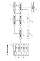
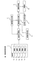
- FIG. 1 is a block diagram showing an example of the system configuration of the mobile control device according to the first embodiment of the present invention.
- the moving body control apparatus 10 controls driving of a moving body (for example, an electric wheelchair) 11 that moves with a user.
- the mobile body control device 10 includes an electroencephalograph 1, a teacher signal generation unit 2, a brain signal separation unit 3, a control signal generation unit 4, a drive control unit 5, and a VISUAL-FEEDBACK unit 6. .
- the mobile control device 10 includes, as main hardware configurations, a CPU (Central Processing Unit) that performs control processing, calculation processing, and the like, and a ROM (Read Read) that stores control programs, calculation programs, and the like executed by the CPU. Only a microcomputer having only (Memory) and RAM (Random Access Memory) that temporarily stores processing data and the like is mainly configured.
- the brain signal separation unit 3, the control signal generation unit 4, the drive control unit 5, the VISUAL-FEEDBACK unit 6, and the stop determination unit 22 described later are realized by software stored in the ROM and executed by the CPU, for example. ing.
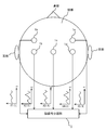
- the electroencephalograph (brain activity detection unit) 1 includes, for example, five electrodes 1a, 1b, 1c, 1d, and 1e arranged on the user's head (FIG. 2), and the primary motion on the user's head. Measure and detect brain activity information around the field.
- the electrodes 1a to 1e can detect brain wave signals such as ⁇ wave (4 to 8 Hz), ⁇ wave (8 to 12 Hz), and ⁇ wave (12 to 40 Hz), which are brain activity information.
- the electrodes 1a to 1e of the electroencephalograph 1 respectively measure the measured user's electroencephalogram signals X1 (t), X2 (t), X3 (t), X4 (t), and X5 (t) (t indicates time) Each is output to the brain signal separation unit 3.
- the teacher signal generator 2 generates a teacher signal for the brain signal separator 3 and the control signal generator 4 as will be described later.
- the teacher signal generation unit 2 includes a posture sensor such as a gyro sensor or an acceleration sensor that can detect the posture value (roll angle, pitch angle, yaw angle, etc.) of the user's head.
- the teacher signal generation unit 2 generates a teacher signal based on the posture value of the user detected by the posture sensor.
- the brain signal separation unit 3 first amplifies the brain wave signals from the electrodes 1a to 1e of the electroencephalograph 1 and converts them into digital signals. Further, the brain signal separation unit 3 executes adaptive processing of a filter that separates and removes artifact components from each amplified and digitized brain wave signal using a blind signal separation algorithm. By removing noise signals (artifacts) induced by the heart, eye muscles, etc. other than brain activity from the electroencephalogram signal, the electroencephalogram signal / noise ratio can be increased and a highly accurate electroencephalogram signal is detected. be able to.
- the blind signal separation algorithm is a well-known signal separation algorithm based on the AMUSE method, and thus detailed description thereof is omitted.
- the brain signal separation unit 3 uses, in advance, an artifact component included in the brain wave signal of the user riding on the moving body 11 based on the teacher signal input from the teacher signal generation unit 2 using a learning algorithm such as a neural network. Learning may be performed to construct an optimum filter for each user. Thereby, according to the characteristic of each user, an artifact component can be separated from an electroencephalogram signal with high accuracy.
- the brain signal separation unit 3 outputs an electroencephalogram signal from which the artifact component is separated to the control signal generation unit 4.
- the control signal generation unit 4 controls the driving of the moving body 11 (for example, forward control, reverse control, right turn control, left turn control, etc.) based on the electroencephalogram signal from the brain signal separation unit 3. (For example, a forward signal, a reverse signal, a right turn signal, a left turn signal, etc.) are generated.
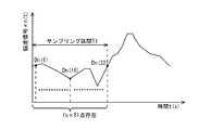
- the control signal generation unit 4 generates the CSP method (Commom Spatial Patterns) based on the electroencephalogram signals X1 (t), X2 (t), X3 (t), X4 (t), and X5 (t), which are short time series
- the feature value fp is continuously calculated by (Method). Then, the control signal generator 4 continuously generates a control signal based on the calculated feature value fp.
- the values (brain data) Dn (1) to Dn (fs ⁇ T1) of the electroencephalogram signal at the point (fs: sampling frequency) are calculated.
- the control signal generation unit 4 uses the electroencephalogram signals X1 (t), X2 (t), X3 (t), X4 (t), and X5 (t) from the electrodes 1a to 1e of the electroencephalograph 1.
- D1 (1) to D1 (fs ⁇ T1), D2 (1) to D2 (fs ⁇ T1), D3 (1) to D3 (fs ⁇ T1), D4 (1) to D4 (fs ⁇ , respectively) T1) and D5 (1) to D5 (fs ⁇ T1) are extracted.
- the control signal generation unit 4 Based on the extracted brain data, the control signal generation unit 4 generates a matrix E composed of 5 (number of electrodes) ⁇ fs ⁇ T1 (number of brain data in the sampling section T1).
- control signal generation unit 4 calculates the feature quantity fp by the following equation (1) based on the generated matrix E and the filters W1 and W2 obtained in advance by the periodic CSP method.
- var (Zp) is a variance of the data string Zp.
- the control signal generation unit 4 performs signal processing with a learning function such as linear SVM (Support Vector Vector Machine) based on the calculated feature value fp, and generates a control signal. Further, the control signal generation unit 4 performs learning by linear SVM using the teacher signal input from the teacher signal generation unit 2 at the time of initial setting in advance, and the feature quantity fp and the control signal (for example, forward signal, reverse signal). , Right turn signal, left turn signal, acceleration signal, deceleration signal, stop signal, etc.).
- a learning function such as linear SVM (Support Vector Vector Machine) based on the calculated feature value fp
- the control signal generation unit 4 performs learning by linear SVM using the teacher signal input from the teacher signal generation unit 2 at the time of initial setting in advance, and the feature quantity fp and the control signal (for example, forward signal, reverse signal). , Right turn signal, left turn signal, acceleration signal, deceleration signal, stop signal, etc.).
- the control signal generation unit 4 uses the linear SVM in an online state automatically or in response to a user operation. Learning may be performed again.
- the control signal generation unit 4 continuously generates a control signal corresponding to the feature quantity fp based on the calculated feature quantity fp and the correspondence relationship between the feature quantity fp and the control signal, and generates the generated control.
- the signals are sequentially output to the drive control unit 5 and the VISUAL-FEEDBACK unit 6.
- the drive control unit 5 sequentially executes the drive control of the moving body 11 in accordance with the continuous control signal from the control signal generation unit 4. For example, the drive control unit 5 advances the moving body 11 in accordance with a forward signal, a reverse signal, a right turn signal, a left turn signal, an acceleration signal, a deceleration signal, and a stop signal from the control signal generation unit 4, respectively. Control, reverse control, right turn control, left turn control, acceleration control, deceleration control, and stop control are executed.
- the drive control unit 5 controls the left and right motors that drive the left and right drive wheels of the electric wheelchair, respectively, so that the forward control, reverse control, right turn control, left turn control, acceleration control, and deceleration of the electric wheelchair are performed. Control and stop control can be executed.
- the drive control unit 5 executes the drive control of the moving body 11 in real time in accordance with the control signal continuously output from the control signal generation unit 4 in a short time. Thereby, highly accurate and smooth drive control of the moving body 11 is realizable at high speed.
- the VISUAL-FEEDBACK unit 6 visually presents the control result to the user according to the continuous control signal from the control signal generation unit 4.
- the VISUAL-FEEDBACK unit 6 represents, for example, right turn, left turn, forward movement, and reverse movement by a right arrow, a left arrow, an up arrow, and a down arrow, respectively.
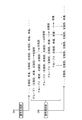
- FIG. 4 is a flowchart illustrating an example of a control processing flow of the mobile control device according to the first embodiment.
- the electrodes 1a to 1e of the electroencephalograph 1 detect the user's brain wave (brain activity detection step) (step S100), and output the detected user's brain wave signal to the brain signal separation unit 3.
- the brain signal separation unit 3 executes adaptive processing of a filter that separates and removes artifact components from the brain wave signals from the respective electrodes 1a to 1e of the electroencephalograph 1 using a blind signal separation algorithm (brain). Signal separation step) (step S101).
- the brain signal separation unit 3 outputs an electroencephalogram signal from which the artifact component is separated to the control signal generation unit 4.
- the drive control part 5 performs drive control of the mobile body 11 according to the continuous control signal from the control signal generation part 4 (drive control process) (step S104).
- the control signal generation unit 4 slides the matrix E by sliding the EEG signals Xn (t) at the predetermined minute time T2 while overlapping the sampling intervals T1. Are continuously generated, and the feature value fp is continuously calculated.
- the drive control part 5 performs the drive control of the mobile body 11 in real time according to the control signal output from the control signal generation part 4 for a short time and continuously.
- the control discrimination in the electroencephalogram signal divided by the sampling interval T1 is continuously repeated in a predetermined minute time T2 while being overlapped, and the macro mobile body 11 is integrated with the control discrimination results for a short time and continuously. Can be controlled. Therefore, high-precision and smooth drive control of the moving body 11 can be realized at high speed (real time).
- the sampling interval T1 is overlapped and slid at a predetermined minute time T2, and the feature quantity fp is continuously calculated to generate a corresponding control signal.
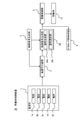
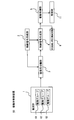
- FIG. 5 is a block diagram showing an example of the system configuration of the mobile control device according to the second embodiment of the present invention.
- the mobile body control device 20 according to the second embodiment further includes a myoelectric potential detection unit 21 and a stop determination unit 22 in addition to the components of the mobile body control device 10 according to the first embodiment. .
- the myoelectric potential detection unit 21 has one or a plurality of myoelectric sensors such as a dry surface electrode, a wet surface electrode, and a silver / silver chloride dish electrode.
- each myoelectric sensor is attached to a part such as a cheek or a neck that can be operated by the user in the heel, and can easily and reliably detect the myoelectric potential of the user.
- Each myoelectric sensor of the myoelectric potential detection unit 21 outputs the detected myoelectric potential as a myoelectric potential signal to the stop determination unit 22.
- the stop determination unit 22 determines whether to stop the moving body 11 based on the myoelectric potential signal from the myoelectric potential detection unit 21. In addition, the stop determination unit 22 outputs a stop signal to the drive control unit 5 when determining that the moving body 11 is to be stopped. When the drive control unit 5 receives the stop signal from the stop determination unit 22, the drive control unit 5 performs stop control of the moving body 11.
- a stop signal is output to the drive control unit 5.
- the drive control unit 5 receives the stop signal from the stop determination unit 22, the drive control unit 5 executes stop control for urgently stopping the moving body 11.
- the stop determination unit 22 determines to stop the mobile body 11 based on the myoelectric signal from the myoelectric sensor of the myoelectric potential detection unit 21, A stop signal is output to the drive control unit 5. And the drive control part 5 will perform stop control of the mobile body 11, if the stop signal from the stop determination part 22 is received. Thereby, the mobile body 11 can be reliably stopped by a user's natural reaction when the mobile body 11 is stopped.
- FIG. 6 is a block diagram showing an example of the system configuration of the mobile control device according to the third embodiment of the present invention.
- the control signal generation unit 34 corresponds to the feature quantity fp based on the calculated feature quantity fp and the correspondence relationship between the feature quantity fp and the control signal.
- the control signal continuously generated by the signal generator 34a that continuously generates the control signal and the signal generator 34a are divided into groups of control signals composed of a predetermined number (for example, three), Each group includes a signal selection unit 34b that selects the most types of control signals in each group.
- the signal selection unit 34b constitutes a group composed of the current control signal and the continuous past control signal.
- the signal selection unit 34b includes the current control signal and the control signals generated one and two times before the control signal as one group.
- the signals and the control signals generated one, two and three times before the control signal may be configured as one group, and any group configuration is applicable. Note that when the number of control signals constituting the group is increased, the accuracy of the generated control signals is increased, and the mobile body 11 can be operated more stably.
- the signal selection part 34b has selected one control signal from each group, it may select not only this but a several control signal.
- the signal selection unit 34 b sequentially outputs the selected control signal to the drive control unit 5 and the VISUAL-FEEDBACK unit 6.
- the signal generation unit 34a continuously generates control signals as “left turn, forward, left turn, left turn, left turn, forward, forward”.
- the signal selection unit 34 b converts the continuous control signals generated by the signal generation unit 34 a into group 1 (left turn, forward, left turn), group 2 (forward, left turn). , Left turn), group 3 (left turn, left turn, left turn), group 4, (left turn, left turn, forward), group 5 (left turn, forward, forward), and so on.
- the signal selection unit 34b selects, for each group, the most frequently used control signal “left turn, left turn, left turn, left turn, left turn” in each group, and sequentially selects the drive control unit 5 and Output to the VISUAL-FEEDBACK unit 6.
- the mobile control device 30 it is possible to improve the accuracy of the control signal generated by the control signal generator 34 and to operate the mobile 11 more stably. It becomes. For example, an unskilled person in the operation of the mobile body 11 may not be able to accurately imagine the operation of the mobile body 11, and thus the electroencephalogram signal may be disturbed. Even in this case, the mobile body control device according to the third embodiment 30 can correct the disturbance of the electroencephalogram and operate the moving body 11 more accurately. It is effective to determine the contents of control based on the above-described majority logic because the disturbance of the brain wave that shows an operation different from the original intention of the user appears instantaneously before the operation is switched.
- the signal selection unit 34b described above selects, for example, a control signal based on a time average, a median value, a statistical value, or the like instead of selecting the most common type of control signal in each group based on the majority logic. Also good.
- the moving body control device 30 according to the third embodiment other configurations are substantially the same as those of the moving body control device 10 according to the first embodiment. Therefore, in the mobile control device 30 according to the third embodiment, the same parts are denoted by the same reference numerals, and detailed description thereof is omitted.
- FIG. 8 is a block diagram showing an example of the system configuration of the mobile control device 40 according to the fourth embodiment of the present invention.
- the mobile control device 40 according to the fourth embodiment further includes a myoelectric potential detection unit 41 in addition to the components of the mobile control device 10 according to the first embodiment.
- the myoelectric potential detection unit 41 generates a myoelectric potential signal indicating a change in the myoelectric potential of the user, like the myoelectric potential detection unit 21 described above.
- the configuration of the myoelectric potential detection unit 41 may be the same as that of the myoelectric potential detection unit 21.
- the generated myoelectric potential signal is supplied to the control signal generation unit 4.
- the control signal generation unit 4 in the present embodiment uses the electroencephalogram signal supplied from the brain signal separation unit 3 and the myoelectric potential signal supplied from the myoelectric potential detection unit 41 in a composite manner, and the drive signal generation unit 5 A control signal to be supplied to is generated. More specifically, the control signal generation unit 4 compares the control content based on the electroencephalogram signal, that is, brain activity information, and the control content based on the myoelectric signal, that is, myoelectric potential. A control signal representing the control content is generated. That is, the operation of the mobile body 11 is controlled using the myoelectric potential preferentially over the brain activity information.
- the control signal generation unit 4 when the brain activity information indicates forward movement and the myoelectric potential indicates stop, the control signal generation unit 4 generates a control signal for causing the moving body 11 to perform a stop operation. In addition, for example, when the brain activity information indicates straight traveling and the myoelectric potential indicates turning to the left or right, the control signal generation unit 4 generates a control signal for causing the moving body 11 to perform a turning operation.
- the present embodiment it is possible to drive and control the moving body 11 more safely.
- the moving body control device 40 according to the present embodiment other configurations are substantially the same as those of the moving body control device 10 according to the first embodiment. Therefore, in the mobile control device 40 according to the fourth embodiment, the same parts are denoted by the same reference numerals, and detailed description thereof is omitted.
- FIG. 9 is a block diagram showing an example of the system configuration of the mobile control device 50 according to the fifth embodiment of the present invention. Electrodes of electroencephalograph 1 of the present embodiment are grouped into a plurality of electrode groups. One electrode group includes at least one electrode. In the example of FIG. 9, the electroencephalograph 1 has three electrode groups G1 to G3.
- the brain signal separation unit 3 digitally samples the analog brain wave signals supplied from the electrodes included in the electrode groups G1 to G3, performs an adaptive filter process using a blind signal separation algorithm, and removes artifact components. A brain wave signal group is generated.
- the signal processing in the brain signal separation unit 3 may be the same as that in the first embodiment.
- the control signal generation unit 4 receives the electroencephalogram signal group from which the artifact component has been removed from the electroencephalogram signal separation unit 3, and uses the electroencephalogram signals for the electrode groups G1 to G3 to move to the electrode groups G1 to G3.
- the control content (for example, forward control, reverse control, right turn control, left turn control, etc.) of the body 11 is determined.
- one control content is determined by majority rating. For example, when the control content determined from the outputs of the electrode groups G1 and G2 is “left turn” and the control content determined from the output of the electrode group 1 is “straight forward”, the control signal generation unit 4 performs “left turn”.
- the control signal shown is supplied to the drive controller 5.
- the brain activity information of the user is detected by the electroencephalograph 1.
- an optical brain measurement device NIRS: Near Infrared Spectroscopy using near infrared light
- NIRS Near Infrared Spectroscopy using near infrared light
- Near-infrared spectroscopy may detect user's brain activity information.
- the electroencephalograph 1 is only an example of a brain activity detection unit.
- the brain activity detection unit any brain measurement device that can detect the brain activity information of the user is applicable.
- a user's brain wave is used as brain activity information, it is not restricted to this, For example, arbitrary brain information, such as hemoglobin oxygenation state information in brain blood, is applicable.
- the electroencephalograph 1 has five electrodes 1a to 1e.
- the present invention is not limited to this.
- one electrode may be used, and the number of configured electrodes may be arbitrary.
- the mounting position on the head may be arbitrary.
- the brain signal separation unit 3 separates the artifact component from each brain wave signal by using a blind signal separation algorithm.
- the present invention is not limited to this, and the artifact component is separated from each brain wave signal. Any signal separation algorithm can be used if are properly separated.
- the drive control unit 5 drives the mobile body 11 corresponding to the control signal only when the same control signal is continuously received from the control signal generation unit 4 a predetermined number of times or more. It may have a limiter function for executing control. Thereby, the moving body 11 can be driven and controlled with higher accuracy.
- an electric wheelchair is applied as the moving body 11, but the present invention is not limited to this, and the present invention can be applied to any moving device that travels with a user. Further, the present invention can be applied to a robot other than a moving device, a cursor on a PC, or the like as a control target.
- control signal generation units 4 and 34 calculate the feature quantity fp by the following equation (1) based on the generated matrix E.
- the present invention is not limited to this.
- the feature quantity of the electroencephalogram signal may be calculated using a calculation method.
- the visual-feedback unit 6 visually presents the control result to the user according to the continuous control signal from the control signal generation unit 4.
- the control result may be presented to the user, and any perceptualization that can be perceived by the user The method can be used.
- the first to fifth embodiments described above may be combined as appropriate.
Landscapes
- Engineering & Computer Science (AREA)
- General Engineering & Computer Science (AREA)
- Theoretical Computer Science (AREA)
- Health & Medical Sciences (AREA)
- General Health & Medical Sciences (AREA)
- Human Computer Interaction (AREA)
- Life Sciences & Earth Sciences (AREA)
- Neurology (AREA)
- Dermatology (AREA)
- Physics & Mathematics (AREA)
- General Physics & Mathematics (AREA)
- Biomedical Technology (AREA)
- Neurosurgery (AREA)
- Animal Behavior & Ethology (AREA)
- Public Health (AREA)
- Veterinary Medicine (AREA)
- Measurement And Recording Of Electrical Phenomena And Electrical Characteristics Of The Living Body (AREA)
- Measurement Of The Respiration, Hearing Ability, Form, And Blood Characteristics Of Living Organisms (AREA)
- Selective Calling Equipment (AREA)
Abstract
Description
この一態様において、前記制御信号生成部は、前記筋電位検出部により検出された前記筋電位に基づいて、制御信号を生成し、前記駆動制御部は、前記筋電位に基づいて生成された制御信号と、前記脳活動情報に基づいて生成された制御信号と、を比較し相違する場合に、前記筋電位に基づいて生成された制御信号に基づいて前記移動体を駆動制御する、若しくは停止させてもよい。
図1は、本発明の第1実施形態に係る移動体制御装置のシステム構成の一例を示すブロック図である。第1実施形態に係る移動体制御装置10は、ユーザを乗せて移動する移動体(例えば、電動車椅子等)11の駆動を制御するものである。移動体制御装置10は、脳波計1と、教師信号生成部2と、脳信号分離部3と、制御信号生成部4と、駆動制御部5と、VISUAL-FEEDBACK部6と、を備えている。


図5は、本発明の第2実施形態に係る移動体制御装置のシステム構成の一例を示すブロック図である。第2実施形態に係る移動体制御装置20は、第1実施形態に係る移動体制御装置10の構成要素に加えて、更に、筋電位検出部21と、停止判断部22と、を備えている。
図6は、本発明の第3実施形態に係る移動体制御装置のシステム構成の一例を示すブロック図である。第3実施形態に係る移動体制御装置30において、制御信号生成部34は、算出された特徴量fpと、上記特徴量fpと制御信号との対応関係と、に基づいて、特徴量fpに対応する制御信号を連続的に生成する信号生成部34aと、信号生成部34aにより連続的に生成される制御信号を、連続する所定個数(例えば、3個)からなる制御信号のグループに分けて、グループ毎に、各グループの中で最も多い種類の制御信号を選択する信号選択部34bと、を有している。
上述した第2実施形態では、筋電位の検出結果を用いて移動体11の停止制御を行う例を示した。しかしながら、筋電位の利用は、停止制御に限られない。本実施形態では、脳活動情報に基づく移動体11の制御と筋電位に基づく移動体11の制御を統合した具体例について説明する。
上述した第2実施形態では、脳波計によって得られる脳波信号の出力をサンプリングし、各サンプルによって表わされる制御内容に対して時間方向での多数決評定を行う例を示した。本実施の形態では、脳波計が有する複数のセンサ(例えば電極)を3つ以上のセンサグループ(例えば電極グループ)に分け、各センサグループの同時刻の出力によって表わされる制御内容が互いに相違する場合に、多数決評定によって1の制御内容を選択する。
1a、1b、1c、1d、1e 電極
2 教師信号生成部
3 脳信号分離部
4、34 制御信号生成部
5 駆動制御部
6 VISUAL-FEEDBACK部
10、20、30、40、50 移動体制御装置
11 移動体
21、41 筋電位検出部
22 停止判断部
34a 信号生成部
34b 信号選択部
G1、G2、G3 電極グループ
Claims (15)
- ユーザの脳活動情報を検出する脳活動検出手段と、
前記脳活動検出手段により検出された前記脳活動情報から、アーチファクト成分を分離する脳信号分離手段と、
前記脳信号分離手段により前記アーチファクト成分が分離された前記脳活動情報において、脳データを抽出するためのサンプリング区間を、オーバーラップさせつつ所定間隔でスライドさせると共に、該スライドさせた各サンプリング区間内の前記脳データに対する特徴量を夫々算出し、該算出された特徴量に基づいて、制御信号を生成する制御信号生成手段と、
前記制御信号生成手段により生成された前記制御信号に基づいて、ユーザが乗る移動体を駆動制御する駆動制御手段と、を備える移動体制御装置。 - 請求項1記載の移動体制御装置であって、
教師信号を生成する教師信号生成手段を更に備え、
前記脳信号分離手段は、前記教師信号生成手段により生成された前記教師信号を用いて、学習を行い、ユーザに応じた前記アーチファクト成分を分離する、移動体制御装置。 - 請求項1又は2記載の移動体制御装置であって、
教師信号を生成する教師信号生成手段を更に備え、
前記制御信号生成手段は、前記教師信号生成手段により生成された前記教師信号を用いて、前記特徴量と前記制御信号との対応関係を算出し、前記特徴量と、前記算出した対応関係とに基づいて、前記制御信号を生成する、移動体制御装置。 - 請求項1乃至3のうちいずれか1項記載の移動体制御装置であって、
ユーザの筋電位を検出する筋電位検出手段と、
前記筋電位検出手段により検出された前記筋電位に基づいて、前記移動体を停止させるか否かを判断する停止判断手段と、を更に備え、
前記停止判断手段により前記移動体を停止させると判断されたとき、前記駆動制御手段は、前記移動体を停止させる制御を行う、移動体制御装置。 - 請求項1乃至4のうちいずれか1項記載の移動体制御装置であって、
前記駆動制御手段は、前記制御信号生成手段から同一の前記制御信号を、所定回数以上連続して受信したとき、該制御信号に対応する制御を実行する、移動体制御装置。 - 請求項1乃至5のうちいずれか1項記載の移動体制御装置であって、
前記脳活動検出手段は、ユーザの脳波信号を検出する複数のセンサを有し、
前記制御信号生成手段は、前記複数のセンサにより夫々検出され、前記アーチファクト成分が分離された複数の前記脳波信号において、脳データを抽出するためのサンプリング区間を、オーバーラップさせつつ所定間隔でスライドさせると共に、該スライドさせた各サンプリング区間内の前記脳データに対する特徴量を夫々算出し、該算出された複数の特徴量に基づいて、複数の制御信号を生成する、移動体制御装置。 - 請求項1乃至6のうちいずれか1項記載の移動体制御装置であって、
前記制御信号生成手段は、
前記算出された特徴量と、予め設定された前記特徴量と制御信号との対応関係と、に基づいて、前記特徴量に対応する制御信号を連続的に生成する信号生成部と、
前記信号生成部により連続的に生成される制御信号を、連続する所定個数からなる制御信号のグループに分けて、各グループの中から少なくとも1つの制御信号を選択し、前記駆動制御手段に対して出力する信号選択部と、
を有する、移動体制御装置。 - 請求項7記載の移動体制御装置であって、
前記信号選択部は、グループ毎に、各グループの中で最も多い種類の制御信号を選択し、前記駆動制御手段に対して出力する、移動体制御装置。 - 請求項7又は8記載の移動体制御装置であって、
前記信号選択部は、現在の制御信号と連続する過去の制御信号とからなる前記グループを構成する、移動体制御装置。 - 請求項1乃至3のうちいずれか1項記載の移動体制御装置であって、
ユーザの筋電位を検出する筋電位検出手段をさらに備え、
前記制御信号生成手段は、
前記筋電位検出手段により検出された前記筋電位に基づいて前記制御信号を生成可能であり、
前記脳活動情報に基づく制御内容と前記筋電位に基づく制御内容とが相違する場合に、前記筋電位に基づく制御内容を示す前記制御信号を前記駆動制御部に供給する、
移動体制御装置。 - 請求項1乃至5のうちいずれか1項記載の移動体制御装置であって、
前記制御信号生成手段は、前記特徴量を用いた判定を逐次行い、逐次行った複数の判定結果に対する多数決によって1の制御内容を決定し、
前記多数決により決定された制御内容を示す前記制御信号を前記駆動制御部に供給する、
移動体制御装置。 - 請求項1乃至5のうちいずれか1項記載の移動体制御装置であって、
前記脳活動検出手段は、少なくとも3つのセンサグループを含み、
前記少なくとも3つのセンサグループの各々は、ユーザの脳波信号を検出する少なくとも1つのセンサを含み、
前記制御信号生成手段は、各センサグループによって検出される脳活動情報に基づく制御内容が相違する場合に多数決によって1の制御内容を決定し、
前記多数決により決定された制御内容を示す前記制御信号を前記駆動制御部に供給する、
移動体制御装置。 - 請求項1乃至12のうちいずれか1項記載の移動体制御装置であって、
前記制御信号生成手段により生成された前記制御信号に基づいて、制御結果をユーザに知覚させる知覚化手段を更に備える、移動体制御装置。 - 請求項13記載の移動体制御装置であって、
前記知覚化手段は、前記制御結果を視覚化するVISUAL-FEEDBACK部である、移動体制御装置。 - ユーザの脳活動情報を検出する脳活動検出工程と、
前記脳活動検出工程で検出された前記脳活動情報から、アーチファクト成分を分離する脳信号分離工程と、
前記脳信号分離工程で前記アーチファクト成分が分離された前記脳活動情報において、脳データを抽出するためのサンプリング区間を、オーバーラップさせつつ所定間隔でスライドさせると共に、該スライドさせた各サンプリング区間内の前記脳データに対する特徴量を夫々算出する特徴量算出工程と、
前記特徴量算出工程で算出された前記特徴量に基づいて、制御信号を生成する制御信号生成工程と、
前記制御信号生成工程で生成された前記制御信号に基づいて、ユーザが乗る移動体を駆動制御する駆動制御工程と、を含む移動体制御方法。
Priority Applications (3)
| Application Number | Priority Date | Filing Date | Title |
|---|---|---|---|
| JP2010535630A JP5167368B2 (ja) | 2008-10-29 | 2009-09-18 | 移動体制御装置及び移動体制御方法 |
| CN200980143412.8A CN102202569B (zh) | 2008-10-29 | 2009-09-18 | 移动体控制装置和移动体控制方法 |
| US13/060,082 US20110152709A1 (en) | 2008-10-29 | 2009-09-18 | Mobile body control device and mobile body control method |
Applications Claiming Priority (2)
| Application Number | Priority Date | Filing Date | Title |
|---|---|---|---|
| JP2008-278348 | 2008-10-29 | ||
| JP2008278348 | 2008-10-29 |
Publications (1)
| Publication Number | Publication Date |
|---|---|
| WO2010050113A1 true WO2010050113A1 (ja) | 2010-05-06 |
Family
ID=42128487
Family Applications (1)
| Application Number | Title | Priority Date | Filing Date |
|---|---|---|---|
| PCT/JP2009/004749 Ceased WO2010050113A1 (ja) | 2008-10-29 | 2009-09-18 | 移動体制御装置及び移動体制御方法 |
Country Status (4)
| Country | Link |
|---|---|
| US (1) | US20110152709A1 (ja) |
| JP (1) | JP5167368B2 (ja) |
| CN (1) | CN102202569B (ja) |
| WO (1) | WO2010050113A1 (ja) |
Cited By (4)
| Publication number | Priority date | Publication date | Assignee | Title |
|---|---|---|---|---|
| JP2013004006A (ja) * | 2011-06-21 | 2013-01-07 | Aisin Seiki Co Ltd | 脳波インターフェースシステム |
| JP2016514022A (ja) * | 2013-03-14 | 2016-05-19 | パーシスト ディベロップメント コーポレーション | qEEGの算出方法およびシステム |
| JP2017202183A (ja) * | 2016-05-12 | 2017-11-16 | 株式会社国際電気通信基礎技術研究所 | 脳波パターン分類装置、脳波パターン分類方法、脳波パターン分類プログラムおよびニューロフィードバックシステム |
| KR20240118557A (ko) * | 2023-01-27 | 2024-08-05 | 국방과학연구소 | 다양한 직관적 뇌-컴퓨터 인터페이스 패러다임 기반 군집 드론 제어 시스템 및 그 방법 |
Families Citing this family (16)
| Publication number | Priority date | Publication date | Assignee | Title |
|---|---|---|---|---|
| KR101031507B1 (ko) * | 2010-07-28 | 2011-04-29 | (주)아이맥스 | 휴대용 뇌파 측정 및 제어 시스템 |
| US20130138248A1 (en) * | 2011-11-30 | 2013-05-30 | Honeywell International Inc. | Thought enabled hands-free control of multiple degree-of-freedom systems |
| CN103150007B (zh) * | 2011-12-06 | 2016-03-30 | 联想(北京)有限公司 | 一种输入方法及装置 |
| CN102880098A (zh) * | 2012-10-07 | 2013-01-16 | 西北农林科技大学 | 一种基于脑电波轮椅控制器 |
| US20150338917A1 (en) * | 2012-12-26 | 2015-11-26 | Sia Technology Ltd. | Device, system, and method of controlling electronic devices via thought |
| JP2014159766A (ja) * | 2013-02-19 | 2014-09-04 | Denso Corp | 移動体用制御システム |
| CN103750845B (zh) * | 2014-01-06 | 2016-05-04 | 西安交通大学 | 一种自动去除近红外光谱信号运动伪迹的方法 |
| CN104665790A (zh) * | 2015-01-26 | 2015-06-03 | 周常安 | 耳戴式生理检测装置 |
| CN105534648A (zh) * | 2016-01-14 | 2016-05-04 | 马忠超 | 基于脑电波结合头部动作的轮椅控制方法及控制装置 |
| EP3510986B1 (en) * | 2016-09-06 | 2024-06-05 | Cyberdyne Inc. | Mobility device and mobility system |
| CN106648080A (zh) * | 2016-12-06 | 2017-05-10 | 青岛海信电器股份有限公司 | 一种基于脑电波的设备控制方法及装置 |
| CN107854127B (zh) * | 2017-10-30 | 2021-04-09 | 苏州大学 | 一种运动状态的检测方法及装置 |
| CN108399006B (zh) * | 2018-02-11 | 2020-06-02 | Oppo广东移动通信有限公司 | 信号处理方法及相关产品 |
| CN108399007B (zh) * | 2018-02-11 | 2021-08-24 | Oppo广东移动通信有限公司 | 脑电波的采样区间调整方法及相关产品 |
| CN110033772B (zh) * | 2019-04-28 | 2021-04-20 | 中国科学院上海高等研究院 | 基于ppg信号的非声学语音信息检测装置 |
| CN114153159B (zh) * | 2020-09-08 | 2024-12-20 | 大金工业株式会社 | 移动体控制方法及装置 |
Citations (10)
| Publication number | Priority date | Publication date | Assignee | Title |
|---|---|---|---|---|
| JPH1119075A (ja) * | 1997-07-04 | 1999-01-26 | Nissan Motor Co Ltd | メンタルストレス判定装置 |
| JPH11318843A (ja) * | 1998-05-21 | 1999-11-24 | Univ Kyoto | 脳波測定方法 |
| US6587713B1 (en) * | 2001-12-14 | 2003-07-01 | Bertha Freeman | Brainwave responsive wheelchair |
| US20030171689A1 (en) * | 2000-05-16 | 2003-09-11 | Jose Millan | System for detecting brain activity |
| JP2004152002A (ja) * | 2002-10-30 | 2004-05-27 | Mitsubishi Electric Corp | 脳波信号を利用した制御装置 |
| US20040117098A1 (en) * | 2002-12-12 | 2004-06-17 | Ryu Chang Su | Apparatus and method for controlling vehicle brake using brain waves |
| JP2005143896A (ja) * | 2003-11-17 | 2005-06-09 | Nissan Motor Co Ltd | 運転者心理状態判定装置 |
| JP2006051343A (ja) * | 2004-07-16 | 2006-02-23 | Semiconductor Energy Lab Co Ltd | 生体信号処理装置、無線メモリ、生体信号処理システム及び被制御装置の制御システム |
| JP2006192105A (ja) * | 2005-01-14 | 2006-07-27 | Nippon Koden Corp | 生体情報表示システム |
| JP2007202882A (ja) * | 2006-02-03 | 2007-08-16 | Advanced Telecommunication Research Institute International | 活動補助システム |
Family Cites Families (8)
| Publication number | Priority date | Publication date | Assignee | Title |
|---|---|---|---|---|
| JPH11198075A (ja) * | 1998-01-08 | 1999-07-27 | Mitsubishi Electric Corp | 行動支援装置 |
| JP4687935B2 (ja) * | 2000-03-13 | 2011-05-25 | 国立大学法人北海道大学 | 個人適応型生体信号被動機器制御システム |
| WO2002100267A1 (en) * | 2001-06-13 | 2002-12-19 | Compumedics Limited | Methods and apparatus for monitoring consciousness |
| AU2004290588A1 (en) * | 2003-11-18 | 2005-06-02 | Vivometrics, Inc. | Method and system for processing data from ambulatory physiological monitoring |
| WO2006121455A1 (en) * | 2005-05-10 | 2006-11-16 | The Salk Institute For Biological Studies | Dynamic signal processing |
| CN101259015B (zh) * | 2007-03-06 | 2010-05-26 | 李小俚 | 一种脑电信号分析监测方法及其装置 |
| WO2009042170A1 (en) * | 2007-09-26 | 2009-04-02 | Medtronic, Inc. | Therapy program selection |
| CN101138495B (zh) * | 2007-10-25 | 2010-11-24 | 中国科学院昆明动物研究所 | 一种电刺激噪声消除仪 |
-
2009
- 2009-09-18 US US13/060,082 patent/US20110152709A1/en not_active Abandoned
- 2009-09-18 CN CN200980143412.8A patent/CN102202569B/zh not_active Expired - Fee Related
- 2009-09-18 JP JP2010535630A patent/JP5167368B2/ja not_active Expired - Fee Related
- 2009-09-18 WO PCT/JP2009/004749 patent/WO2010050113A1/ja not_active Ceased
Patent Citations (10)
| Publication number | Priority date | Publication date | Assignee | Title |
|---|---|---|---|---|
| JPH1119075A (ja) * | 1997-07-04 | 1999-01-26 | Nissan Motor Co Ltd | メンタルストレス判定装置 |
| JPH11318843A (ja) * | 1998-05-21 | 1999-11-24 | Univ Kyoto | 脳波測定方法 |
| US20030171689A1 (en) * | 2000-05-16 | 2003-09-11 | Jose Millan | System for detecting brain activity |
| US6587713B1 (en) * | 2001-12-14 | 2003-07-01 | Bertha Freeman | Brainwave responsive wheelchair |
| JP2004152002A (ja) * | 2002-10-30 | 2004-05-27 | Mitsubishi Electric Corp | 脳波信号を利用した制御装置 |
| US20040117098A1 (en) * | 2002-12-12 | 2004-06-17 | Ryu Chang Su | Apparatus and method for controlling vehicle brake using brain waves |
| JP2005143896A (ja) * | 2003-11-17 | 2005-06-09 | Nissan Motor Co Ltd | 運転者心理状態判定装置 |
| JP2006051343A (ja) * | 2004-07-16 | 2006-02-23 | Semiconductor Energy Lab Co Ltd | 生体信号処理装置、無線メモリ、生体信号処理システム及び被制御装置の制御システム |
| JP2006192105A (ja) * | 2005-01-14 | 2006-07-27 | Nippon Koden Corp | 生体情報表示システム |
| JP2007202882A (ja) * | 2006-02-03 | 2007-08-16 | Advanced Telecommunication Research Institute International | 活動補助システム |
Non-Patent Citations (2)
| Title |
|---|
| MASAHARU MIZUGUCHI: "Powered Wheelchair Steered through Voice Commands", IEICE TECHNICAL REPORT, vol. 108, no. 67, 22 May 2008 (2008-05-22), pages 49 - 50 * |
| YUTAKA ICHINOSE: "Human Interface Using a Wireless Tongue-Palate Contact Pressure Sensor System and Its Application to the Control of an Electric Wheelchair", THE TRANSACTIONS OF THE INSTITUTE OF ELECTRONICS, INFORMATION AND COMMUNICATION ENGINEERS (J86-D-II), vol. 2, 1 February 2003 (2003-02-01), pages 364 - 367 * |
Cited By (5)
| Publication number | Priority date | Publication date | Assignee | Title |
|---|---|---|---|---|
| JP2013004006A (ja) * | 2011-06-21 | 2013-01-07 | Aisin Seiki Co Ltd | 脳波インターフェースシステム |
| JP2016514022A (ja) * | 2013-03-14 | 2016-05-19 | パーシスト ディベロップメント コーポレーション | qEEGの算出方法およびシステム |
| JP2017202183A (ja) * | 2016-05-12 | 2017-11-16 | 株式会社国際電気通信基礎技術研究所 | 脳波パターン分類装置、脳波パターン分類方法、脳波パターン分類プログラムおよびニューロフィードバックシステム |
| KR20240118557A (ko) * | 2023-01-27 | 2024-08-05 | 국방과학연구소 | 다양한 직관적 뇌-컴퓨터 인터페이스 패러다임 기반 군집 드론 제어 시스템 및 그 방법 |
| KR102861163B1 (ko) | 2023-01-27 | 2025-09-17 | 국방과학연구소 | 다양한 직관적 뇌-컴퓨터 인터페이스 패러다임 기반 군집 드론 제어 시스템 및 그 방법 |
Also Published As
| Publication number | Publication date |
|---|---|
| CN102202569A (zh) | 2011-09-28 |
| JP5167368B2 (ja) | 2013-03-21 |
| JPWO2010050113A1 (ja) | 2012-03-29 |
| CN102202569B (zh) | 2014-05-07 |
| US20110152709A1 (en) | 2011-06-23 |
Similar Documents
| Publication | Publication Date | Title |
|---|---|---|
| JP5167368B2 (ja) | 移動体制御装置及び移動体制御方法 | |
| Deng et al. | A bayesian shared control approach for wheelchair robot with brain machine interface | |
| CN109310561B (zh) | 运动示教系统和运动示教方法 | |
| Leeb et al. | Brain–computer communication: motivation, aim, and impact of exploring a virtual apartment | |
| Tomari et al. | Development of smart wheelchair system for a user with severe motor impairment | |
| Han et al. | A novel system of SSVEP-based human–robot coordination | |
| US7963930B2 (en) | Methods and devices of multi-functional operating system for care-taking machine | |
| Yathunanthan et al. | Controlling a wheelchair by use of EOG signal | |
| Villani et al. | A framework for affect-based natural human-robot interaction | |
| KR20120040429A (ko) | 사용자의 생체정보 분석을 통한 감정상태 분석장치 및 방법 | |
| Gergondet et al. | Using brain-computer interface to steer a humanoid robot | |
| CN116561698A (zh) | 一种多源数据融合人机交互任务在线加速方法与系统 | |
| Ogenga et al. | Development of a virtual environment-based electrooculogram control system for safe electric wheelchair mobility for individuals with severe physical disabilities | |
| Satti et al. | Self-paced brain-controlled wheelchair methodology with shared and automated assistive control | |
| JP2009285294A (ja) | 脳訓練支援装置 | |
| WO2024125240A1 (zh) | 一种动作训练方法及采用该方法的训练装置 | |
| Tamura et al. | Mouse cursor control system using electrooculogram signals | |
| KR101539923B1 (ko) | 이중 기계학습 구조를 이용한 생체신호 기반의 안구이동추적 시스템 및 이를 이용한 안구이동추적 방법 | |
| KR20210055424A (ko) | 비정상 근육 시너지 패턴 교정 훈련 장치 및 이를 이용한 피험자의 근육 시너지 패턴 교정 훈련 방법 | |
| Kim-Tien et al. | Using electrooculogram and electromyogram for powered wheelchair | |
| KR101435905B1 (ko) | 안전도와 근전도를 이용한 전자기기 제어 방법 및 장치 | |
| Jaison et al. | Brain-Powered Vehicles for Individuals with Disabilities Leveraging AI | |
| JPH10244480A (ja) | ロボットの制御装置 | |
| CN113688660A (zh) | 计算机实现的方法、数据处理装置、非侵入性脑电接口系统和非暂时性计算机可读介质 | |
| Zaway et al. | Hybrid Wheelchair control method with EEG signal and facial Expression |
Legal Events
| Date | Code | Title | Description |
|---|---|---|---|
| WWE | Wipo information: entry into national phase |
Ref document number: 200980143412.8 Country of ref document: CN |
|
| 121 | Ep: the epo has been informed by wipo that ep was designated in this application |
Ref document number: 09823229 Country of ref document: EP Kind code of ref document: A1 |
|
| WWE | Wipo information: entry into national phase |
Ref document number: 2010535630 Country of ref document: JP |
|
| WWE | Wipo information: entry into national phase |
Ref document number: 13060082 Country of ref document: US |
|
| NENP | Non-entry into the national phase |
Ref country code: DE |
|
| 122 | Ep: pct application non-entry in european phase |
Ref document number: 09823229 Country of ref document: EP Kind code of ref document: A1 |