WO2010050106A1 - 画像符号化方法、画像符号化装置および撮像システム - Google Patents
画像符号化方法、画像符号化装置および撮像システム Download PDFInfo
- Publication number
- WO2010050106A1 WO2010050106A1 PCT/JP2009/004108 JP2009004108W WO2010050106A1 WO 2010050106 A1 WO2010050106 A1 WO 2010050106A1 JP 2009004108 W JP2009004108 W JP 2009004108W WO 2010050106 A1 WO2010050106 A1 WO 2010050106A1
- Authority
- WO
- WIPO (PCT)
- Prior art keywords
- orthogonal transform
- image
- edge
- transform size
- flat part
- Prior art date
Links
Images


Classifications
-
- H—ELECTRICITY
- H04—ELECTRIC COMMUNICATION TECHNIQUE
- H04N—PICTORIAL COMMUNICATION, e.g. TELEVISION
- H04N5/00—Details of television systems
- H04N5/76—Television signal recording
- H04N5/765—Interface circuits between an apparatus for recording and another apparatus
- H04N5/77—Interface circuits between an apparatus for recording and another apparatus between a recording apparatus and a television camera
- H04N5/772—Interface circuits between an apparatus for recording and another apparatus between a recording apparatus and a television camera the recording apparatus and the television camera being placed in the same enclosure
-
- H—ELECTRICITY
- H04—ELECTRIC COMMUNICATION TECHNIQUE
- H04N—PICTORIAL COMMUNICATION, e.g. TELEVISION
- H04N19/00—Methods or arrangements for coding, decoding, compressing or decompressing digital video signals
- H04N19/10—Methods or arrangements for coding, decoding, compressing or decompressing digital video signals using adaptive coding
- H04N19/102—Methods or arrangements for coding, decoding, compressing or decompressing digital video signals using adaptive coding characterised by the element, parameter or selection affected or controlled by the adaptive coding
- H04N19/103—Selection of coding mode or of prediction mode
- H04N19/11—Selection of coding mode or of prediction mode among a plurality of spatial predictive coding modes
-
- H—ELECTRICITY
- H04—ELECTRIC COMMUNICATION TECHNIQUE
- H04N—PICTORIAL COMMUNICATION, e.g. TELEVISION
- H04N19/00—Methods or arrangements for coding, decoding, compressing or decompressing digital video signals
- H04N19/10—Methods or arrangements for coding, decoding, compressing or decompressing digital video signals using adaptive coding
- H04N19/102—Methods or arrangements for coding, decoding, compressing or decompressing digital video signals using adaptive coding characterised by the element, parameter or selection affected or controlled by the adaptive coding
- H04N19/12—Selection from among a plurality of transforms or standards, e.g. selection between discrete cosine transform [DCT] and sub-band transform or selection between H.263 and H.264
- H04N19/122—Selection of transform size, e.g. 8x8 or 2x4x8 DCT; Selection of sub-band transforms of varying structure or type
-
- H—ELECTRICITY
- H04—ELECTRIC COMMUNICATION TECHNIQUE
- H04N—PICTORIAL COMMUNICATION, e.g. TELEVISION
- H04N19/00—Methods or arrangements for coding, decoding, compressing or decompressing digital video signals
- H04N19/10—Methods or arrangements for coding, decoding, compressing or decompressing digital video signals using adaptive coding
- H04N19/134—Methods or arrangements for coding, decoding, compressing or decompressing digital video signals using adaptive coding characterised by the element, parameter or criterion affecting or controlling the adaptive coding
- H04N19/136—Incoming video signal characteristics or properties
- H04N19/14—Coding unit complexity, e.g. amount of activity or edge presence estimation
-
- H—ELECTRICITY
- H04—ELECTRIC COMMUNICATION TECHNIQUE
- H04N—PICTORIAL COMMUNICATION, e.g. TELEVISION
- H04N19/00—Methods or arrangements for coding, decoding, compressing or decompressing digital video signals
- H04N19/10—Methods or arrangements for coding, decoding, compressing or decompressing digital video signals using adaptive coding
- H04N19/169—Methods or arrangements for coding, decoding, compressing or decompressing digital video signals using adaptive coding characterised by the coding unit, i.e. the structural portion or semantic portion of the video signal being the object or the subject of the adaptive coding
- H04N19/17—Methods or arrangements for coding, decoding, compressing or decompressing digital video signals using adaptive coding characterised by the coding unit, i.e. the structural portion or semantic portion of the video signal being the object or the subject of the adaptive coding the unit being an image region, e.g. an object
- H04N19/176—Methods or arrangements for coding, decoding, compressing or decompressing digital video signals using adaptive coding characterised by the coding unit, i.e. the structural portion or semantic portion of the video signal being the object or the subject of the adaptive coding the unit being an image region, e.g. an object the region being a block, e.g. a macroblock
-
- H—ELECTRICITY
- H04—ELECTRIC COMMUNICATION TECHNIQUE
- H04N—PICTORIAL COMMUNICATION, e.g. TELEVISION
- H04N9/00—Details of colour television systems
- H04N9/79—Processing of colour television signals in connection with recording
- H04N9/7921—Processing of colour television signals in connection with recording for more than one processing mode
-
- H—ELECTRICITY
- H04—ELECTRIC COMMUNICATION TECHNIQUE
- H04N—PICTORIAL COMMUNICATION, e.g. TELEVISION
- H04N9/00—Details of colour television systems
- H04N9/79—Processing of colour television signals in connection with recording
- H04N9/80—Transformation of the television signal for recording, e.g. modulation, frequency changing; Inverse transformation for playback
- H04N9/804—Transformation of the television signal for recording, e.g. modulation, frequency changing; Inverse transformation for playback involving pulse code modulation of the colour picture signal components
- H04N9/8042—Transformation of the television signal for recording, e.g. modulation, frequency changing; Inverse transformation for playback involving pulse code modulation of the colour picture signal components involving data reduction
- H04N9/8047—Transformation of the television signal for recording, e.g. modulation, frequency changing; Inverse transformation for playback involving pulse code modulation of the colour picture signal components involving data reduction using transform coding
Definitions
- the present invention provides a plurality of orthogonal transform sizes (for example, 4 ⁇ 4 pixel units and 8 in accordance with the state of an image in order to improve encoding efficiency, perform high-speed processing, and improve image quality degradation in image encoding.
- the present invention relates to a technique for encoding moving images by adaptively switching ( ⁇ 8 pixel units).
- MPEG-4 Part 10 Advanced Video Coding (abbreviated MPEG-4 AVC) developed by ISO / IEC JTC1 MPEG (Moving Picture Experts Group).
- MPEG-4 AVC Advanced Video Coding
- orthogonal transform sizes of 4 ⁇ 4 pixel units and 8 ⁇ 8 pixel units can be selected as the orthogonal transform block size.
- the orthogonal transformation in units of 4 ⁇ 4 pixels has a narrow influence range of noise generated by quantization. Further, the orthogonal transformation in units of 8 ⁇ 8 pixels is easy to reproduce the unevenness in a complicated pattern, but has a wide influence range of noise.
- Patent Document 1 discloses a method for improving the image quality of a block image including a character image such as a caption by switching the orthogonal transform size. Since a block image including a character image includes many edges whose pixel values change sharply, mosquito noise is likely to occur due to image encoding. In Japanese Patent Application Laid-Open No. 2004-228867, by selecting orthogonal transformation in units of 4 ⁇ 4 pixels for a block image including a character image, an area where mosquito noise is diffused is reduced, thereby making it difficult to visually recognize mosquito noise. Make improvements. However, Patent Document 1 only mentions the use of edge detection or the like as a method for selecting an orthogonal transform size, and does not describe a detailed example of the selection method.
- Patent Document 2 discloses a method for selecting an orthogonal transform size by edge detection.
- FIG. 10 shows a flow of the orthogonal transform size selection method of Patent Document 2.
- the orthogonal transform size selection method includes an edge detection step S91 for detecting an edge of the processing target block, an edge determination step S92 for determining whether an edge exists in the processing target block based on the detection result, and an edge exists.
- 4 ⁇ 4 orthogonal transformation selection step S93 for selecting orthogonal transformation in units of 4 ⁇ 4 pixels when determined, and 8 ⁇ 8 orthogonal transformation for selecting orthogonal transformation in units of 8 ⁇ 8 pixels when it is determined that no edge exists.
- a selection step S94 is a selection step S94.
- FIG. 11 shows a block image in which orthogonal transform in units of 4 ⁇ 4 pixels is selected when the orthogonal transform size selection method of Patent Document 2 is applied to an image including a character image such as a caption. It can be seen that 4 ⁇ 4 orthogonal transformation is selected for the block image including the character image at the bottom of the image (a region surrounded by a square with a thick solid line).
- Patent Document 2 has a problem that the code amount greatly increases in a block image in which 4 ⁇ 4 orthogonal transform is selected, particularly when the block image to be processed is an intra prediction mode in which prediction within a frame is performed. is there.
- the reason why the code amount of the block for which 4 ⁇ 4 orthogonal transform is selected increases is that the block size for performing intra prediction differs depending on the orthogonal transform size. Details are as follows.
- the intra prediction method is applied with an 8 ⁇ 8 pixel unit intra prediction method, whereas when the orthogonal transform size is 4 ⁇ 4 pixel units, As the intra prediction method, an intra prediction method in units of 4 ⁇ 4 pixels or an intra prediction method in units of 16 ⁇ 16 pixels is applied.
- intra prediction is performed in units of four 8 ⁇ 8 pixel blocks in a macro block of 16 ⁇ 16 pixels, and each of the four intra prediction modes is encoded. Store in the macroblock header area of the encoded output bitstream.
- the 16 ⁇ 16 pixel macroblock is subjected to intra prediction in units of 16 4 ⁇ 4 pixel blocks, and each of the 16 intra prediction modes is set. Encode and store in the macroblock header of the output bitstream after image encoding. Therefore, the number of intra prediction modes stored in the macroblock header is increased, and the amount of code is significantly increased as compared with the intra prediction method in units of 8 ⁇ 8 pixels.
- the present invention was created in view of such circumstances, and by appropriately selecting an orthogonal transform size for a block including a character image or the like, the mosquito noise of the character image is suppressed while suppressing an increase in the code amount.
- the main purpose is to be able to suppress degradation of image quality due to.
- An image encoding method includes: An image encoding method for performing image encoding on an encoding target block image based on an orthogonal transform with a selected orthogonal transform size after selecting one of a plurality of orthogonal transform sizes in block units, An edge detection step of detecting an edge of the encoding target block image and outputting a detection result as edge information; An edge determination step of determining whether an edge exists in the encoding target block image by comparing the edge information with an edge determination threshold; A flat part detection step of detecting a flat part in the encoding target block image when it is determined that an edge exists in the encoding target block image in the edge determination step, and outputting a detection result as flat part information; A flat portion determination step for determining whether or not a flat portion exists in the encoding target block image by comparing the flat portion information with a flat portion determination threshold;
- the plurality of orthogonal transform sizes are composed of a first orthogonal transform size group composed of one or a plurality of orthogonal transform sizes
- the encoding target block image is included in the first orthogonal transform size group.
- a first orthogonal transform size selection step for selecting one orthogonal transform; When it is determined in the edge determination step that no edge exists in the encoding target block image, or when it is determined in the flat portion determination step that the flat portion does not exist in the encoding target block image.
- the selection conditions are set more finely in selecting the orthogonal transform size. That is, in addition to the determination of the presence of the edge, the determination of the presence of the flat portion is taken into account.
- the processing target block includes an edge and further includes a flat portion
- an orthogonal transform based on one of the first orthogonal transform size groups is selected.
- the processing target block does not include an edge, and when the processing target block includes an edge but does not include a flat portion, the orthogonal transform by one of the second orthogonal transform size groups is selected. Is done.
- the selection of the orthogonal transform size is made more appropriate for a block including a character image and the like, and it is possible to suppress image quality deterioration due to mosquito noise of the character image while suppressing an increase in the code amount.
- the first orthogonal transform size group includes an orthogonal transform size of 4 ⁇ 4 pixels
- the second orthogonal transformation size group includes an orthogonal transformation size of 8 ⁇ 8 pixel units
- In the first orthogonal transform size selection step an orthogonal transform with an orthogonal transform size of the 4 ⁇ 4 pixel unit is selected
- In the second orthogonal transform size selection step an orthogonal transform with an orthogonal transform size of the 8 ⁇ 8 pixel unit is selected.
- There is a mode For example, for block images such as tree branches and leaves, edges are detected, but flat portions are not detected, so orthogonal transform by one of the first orthogonal transform groups (4 ⁇ 4 pixel units, etc.) is selected.
- one of the second orthogonal transform size groups (8 ⁇ 8 pixel unit or the like) is selected.
- an orthogonal size by one of the first orthogonal transform groups is selected. In this way, it is possible to suppress deterioration in image quality due to mosquito noise of character images while suppressing an increase in code amount.
- the edge detection step a difference absolute value of pixels adjacent in the horizontal direction and the vertical direction in the encoding target block image is calculated, and when the calculated difference absolute value is larger than an edge detection threshold, the edge and Edge detection is performed, and the number of detected edges is output as the edge information. There is a mode. According to this configuration, since edge detection is performed based on the absolute difference value between adjacent pixels in the horizontal and vertical directions, it is possible to perform high-speed edge detection with a reduced calculation processing amount.
- the flat part detecting step a difference absolute value of pixels adjacent in the horizontal direction and the vertical direction in the encoding target block image is calculated, and if the calculated difference absolute value is smaller than a flat part detection threshold value, the flat part is detected.
- the flat part detection is performed, and the number of detected flat parts is output as the flat part information. There is a mode. According to this configuration, since the flat portion detection is performed based on the absolute difference value of adjacent pixels in the horizontal and vertical directions, it is possible to perform high-speed flat portion detection with a reduced calculation processing amount.
- An image encoding device includes: An image encoding device that performs image encoding on a block image to be encoded based on orthogonal transform based on a selected orthogonal transform size after selecting orthogonal transforms based on a plurality of orthogonal transform sizes, An edge detection unit that detects an edge of the encoding target block image and outputs a detection result as edge information; An edge determination unit that determines whether or not the encoding target block image includes an edge by comparing the edge information with an edge determination threshold; A flat part detecting unit that detects a flat part of the encoding target block image and outputs a detection result as flat part information; A flat part determination unit that determines whether or not the encoding target block image includes the flat part by comparing the flat part information with a flat part determination threshold; An orthogonal transform size selection unit for selecting an orthogonal transform size; With The orthogonal transform size selection unit includes a first orthogonal transform size group composed of one or a plurality of orthogonal transform sizes and
- the edge determination unit determines that the edge is included in the encoding target block image and the flat portion determination unit If it is determined that the flat part is included in the encoding target block image in step 1, select one of the first orthogonal transform size group, The orthogonal transform size selection unit determines that the edge determination unit determines that the edge is not included in the encoding target block image, or the flat part determination unit includes the flat portion in the encoding target block. If it is determined that it is not, one of the second orthogonal transform size groups is selected.
- the selection condition is set more finely by performing the selection by adding the determination of the presence of the flat portion in addition to the determination of the presence of the edge. Therefore, the selection of the orthogonal transform size is made more appropriate for blocks containing character images, etc., and image quality deterioration due to mosquito noise in character images can be suppressed while suppressing an increase in code amount, which is a great improvement in subjective image quality. effective.
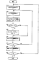
- FIG. 1 is a flowchart showing an operation of selecting an orthogonal transform size in the image coding method according to Embodiment 1 of the present invention.
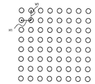
- FIG. 2 is a diagram showing the positional relationship between adjacent pixels for calculating the absolute difference value of the image coding method according to Embodiment 1 of the present invention.
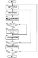
- FIG. 3 is a flowchart showing an edge detection operation in the horizontal direction in the image coding method according to Embodiment 1 of the present invention.
- FIG. 4 is a flowchart showing an edge detection operation in the vertical direction in the image coding method according to Embodiment 1 of the present invention.
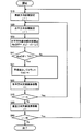
- FIG. 5 is a flowchart showing an operation of detecting a flat portion in the horizontal direction in the image coding method according to Embodiment 1 of the present invention.
- FIG. 6 is a flowchart showing an operation of detecting a flat portion in the vertical direction in the image coding method according to Embodiment 1 of the present invention.
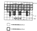
- FIG. 7 is a diagram showing a 4 ⁇ 4 orthogonal transform selection result when the orthogonal transform size selection method of the image coding method according to Embodiment 1 of the present invention is applied to an image.
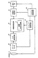
- FIG. 8 is a block diagram showing the configuration of the image coding apparatus according to Embodiment 2 of the present invention.
- FIG. 9 is a block diagram illustrating a configuration of an imaging system according to Embodiment 3 of the present invention.
- FIG. 10 is a flowchart showing a conventional orthogonal transform size selection operation.
- FIG. 11 is a diagram illustrating a 4 ⁇ 4 orthogonal transform selection result when the conventional method is applied to an image.
- FIG. 12 is a diagram illustrating a 4 ⁇ 4 orthogonal transform selection result when the conventional method is applied to an image.
- FIG. 1 is a flowchart of orthogonal transform size selection in the image coding method according to Embodiment 1 of the present invention.
- the orthogonal transform size selection method of the image coding method in Embodiment 1 includes an edge detection step S1, an edge determination step S2, a flat portion detection step S3, a flat portion determination step S4, a 4 ⁇ 4 orthogonal transform selection step S5, and An 8 ⁇ 8 orthogonal transform selection step S6 is included.
- edge detection step S1 an edge where the pixel value changes sharply is detected.
- edge determination step S2 it is determined whether an edge is included in the processing target block based on the detection result in the edge detection step S1.
- flat part detection step S3 when it is determined in the edge determination step S2 that the processing target block includes an edge, a flat part in which the pixel value gradually changes is detected in the processing target block.
- the flat part determination step S4 it is determined whether or not the processing target block includes a flat part based on the detection result in the flat part detection step S3.
- 4 ⁇ 4 orthogonal transform selection step S5 when it is determined in the flat portion determination step S4 that a flat portion is included, orthogonal transform in units of 4 ⁇ 4 pixels is selected.
- the 8 ⁇ 8 orthogonal transform selection step S6 when it is determined in the edge determination step S2 that the processing target block does not include an edge, and in the flat portion determination step S4, it is determined that the processing target block does not include a flat portion.
- an orthogonal transformation in units of 8 ⁇ 8 pixels is selected.
- the 4 ⁇ 4 pixel unit is one of the orthogonal transform sizes constituting the first orthogonal transform size group, and the 8 ⁇ 8 pixel unit has a larger orthogonal transform size size than the first orthogonal transform size group. This is one of the orthogonal transform sizes constituting the two orthogonal transform size groups.
- the first and second orthogonal transform size groups are each composed of one, but the first and second orthogonal transform size groups may be composed of a plurality.
- an edge where the pixel value changes sharply with respect to the processing target block is detected.
- an edge detection method there is a method of detecting using an absolute difference value between adjacent pixels.
- the difference absolute value of adjacent pixels is calculated, and when the calculated difference absolute value is larger than the edge detection threshold (Th1), it is determined as an edge and the number of detected edges (Cnt1) is counted.
- FIG. 2 shows the positional relationship between adjacent pixels for calculating the absolute difference value.
- H1 indicates the positional relationship between adjacent pixels referred to when calculating the absolute difference value in the horizontal direction
- V1 indicates the positional relationship between adjacent pixels referred to when the absolute difference value is calculated in the vertical direction.
- step S1 absolute difference values in the horizontal direction and the vertical direction are calculated. If the adjacent pixel calculation target pixel is x (i, j), the edge detection flow in the horizontal direction is as shown in FIG. The details of the horizontal edge detection flow will be described below with reference to FIG.
- the horizontal edge detection flow includes a vertical initial setting step S10 for initial setting of the vertical pixel position, a horizontal initial setting step S20 for initial setting of the horizontal pixel position, and a horizontal difference absolute value.
- Horizontal difference absolute value calculation step S30 for calculating (AbsDiff), difference absolute value comparison step S40 for comparing the difference absolute value (AbsDiff) with the edge detection threshold (Th1), and the difference absolute value (AbsDiff) being an edge
- the detection threshold (Th1) is greater, the edge count step S50 for increasing the number of edges (Cnt1) by 1, the horizontal target pixel moving step S60 for moving the target pixel by one pixel in the horizontal direction, and the horizontal component Horizontal pixel position determination step S for determining whether the macro block size is smaller than “16” 0, a vertical target pixel moving step S80 for moving the target pixel one pixel in the vertical direction, and a vertical pixel position determining step S90 for determining whether the vertical component is smaller than “16” which is the block size of the processing target block.
- the flow of edge detection in the vertical direction is as shown in FIG.
- the details of the edge detection flow in the vertical direction will be described below with reference to FIG.
- the vertical difference absolute value for calculating the vertical difference absolute value is calculated.
- a calculation step S31 is provided.
- edge determination step S2 when the number of edges (Cnt1) counted in the edge detection step S1 is larger than the edge determination threshold (Th2), it is determined that the processing target block includes an edge, and edge determination is performed. When the threshold value (Th2) or less, it is determined that the processing target block does not include an edge.
- a flat portion in which the pixel value gently changes with respect to the processing target block is detected.
- a method for detecting a flat portion there is a method using an absolute difference value of adjacent pixels as in edge detection. The difference absolute value of adjacent pixels is calculated, and when the calculated difference absolute value is larger than the flat part detection threshold (Th3), it is determined as a flat part, and the number of flat parts (Cnt2) detected by this determination is calculated. Count.
- the horizontal flat portion detection flow includes a vertical direction initial setting step S10 for initial setting of a vertical pixel position, a horizontal direction initial setting step S20 for initial setting of a horizontal pixel position, and an absolute difference in the horizontal direction.
- a vertical target pixel moving step S80 for moving the target pixel by one pixel in the vertical direction
- a vertical pixel position determining step S90 for determining whether the vertical component is smaller than “16” which is the block size of the processing target block.
- the flow of detecting the flat portion in the vertical direction is as shown in FIG.
- the flow of detecting the flat portion in the vertical direction will be described with reference to FIG.
- the vertical direction difference is calculated in the vertical direction flat part detection flow.
- An absolute value calculating step S31 is provided.
- the flat portion determination step S4 when the number of flat portions counted in the flat portion detection step S3 is larger than the flat portion determination threshold value (Th4), it is determined that the processing target block includes a flat portion, and the flat portion is flat. When it is equal to or less than the part determination threshold (Th4), it is determined that the flat block is not included in the processing target block.
- the 4 ⁇ 4 pixel unit which is one of the first orthogonal transform size groups, is selected only when the processing target block includes an edge and further includes a flat portion.
- 8 ⁇ which is one of the second orthogonal transform size groups
- An 8-pixel unit is selected. This is a feature of the present embodiment in comparison with the prior art.
- the selection of the pixel unit described above selects an arbitrary pixel unit in each of the first and second orthogonal transform size groups. Just do it.
- the first orthogonal transform size group (4 ⁇ 4 orthogonal transform size, etc.) is selected. There is no. Further, for a block image including a character image, an edge is detected and a flat portion is also detected, so that the first orthogonal transform size group (4 ⁇ 4 orthogonal transform size or the like) can be selected.
- FIG. 7 shows the result of the orthogonal transform size using the orthogonal transform size selection method of the first embodiment.
- the orthogonal transform size selection method of the present embodiment in a block including only edges such as tree branches and leaves, one of the second orthogonal transform size groups (8 ⁇ 8 orthogonal transform size, etc.) is selected, It can be seen that one block (4 ⁇ 4 orthogonal transform size, etc.) in the first orthogonal transform size group is selected as a block including a character image in which both edges and flat portions exist.
- the first orthogonal transform size group (4 ⁇ 4 orthogonal transform size) is also selected for the trunk portion of the tree. In the tree portion, the region where the first orthogonal transform size group is selected is greatly reduced as compared with FIG. 11 of the prior art, and the code amount is reduced.
- the method of using the adjacent pixel difference absolute value is described as the method of edge detection and flat portion detection.
- the present invention is not limited to this.
- FIG. 8 is a block diagram showing the configuration of the image coding apparatus A according to Embodiment 2 of the present invention.
- the image coding apparatus A according to Embodiment 3 includes a block division unit 1, an edge detection unit 2, an edge determination unit 3, a flat portion detection unit 4, a flat portion determination unit 5, and an orthogonal transform size selection unit 6.
- the block division unit 1 performs division for each block in the input image.
- the edge detection unit 2 detects edges in the block image (encoding target block) obtained by the block division unit 1 and outputs the detection results as edge information.
- the edge detection performed by the edge detection unit 2 is performed by the same method as the edge detection described in the first embodiment.
- the edge determination unit 3 determines whether or not an edge is included in the block image by comparing the edge information output from the edge detection unit 2 with an edge determination threshold value.
- the flat part detecting unit 4 detects a flat part in the block image obtained by the block dividing unit 1 and outputs the detection result as flat part information.
- the flat part detection performed by the flat part detection unit 4 is performed by the same method as the flat part detection described in the first embodiment.
- the flat part determination unit 5 determines whether or not the block image includes a flat part by comparing the flat part information output from the flat part detection unit 4 with a flat part determination threshold value.
- the orthogonal transform size selection unit 6 performs size selection for orthogonal transform based on the determination results of the edge determination unit 3 and the flat portion determination unit 5.
- the selector 7 receives an instruction from the orthogonal transform size selection unit 6 and switches between 4 ⁇ 4 orthogonal transform size and 8 ⁇ 8 orthogonal transform size.
- the 4 ⁇ 4 orthogonal transform size is an example in the first orthogonal transform size group
- the 8 ⁇ 8 orthogonal transform size is an example in the second orthogonal transform size group. Needless to say.
- the first orthogonal transform unit 8 performs 4 ⁇ 4 orthogonal transform.
- the first quantization unit 9 quantizes the transform coefficient obtained by the first orthogonal transform unit 8.
- the second orthogonal transform unit 10 performs 8 ⁇ 8 orthogonal transform.
- the second quantization unit 11 performs quantization on the transform coefficient obtained by the second orthogonal transform unit 10.
- the selector 12 switches the outputs of the first quantization unit 9 and the second quantization unit 11 based on an instruction from the orthogonal transform size selection unit 6.
- the entropy encoding unit 13 encodes the quantized coefficient output from the selector 12.
- the inverse quantization unit 14 performs inverse quantization on the quantization coefficient output from the selector 12.
- the inverse orthogonal transform unit 15 performs inverse orthogonal transform on the transform coefficient obtained by the inverse quantization unit 14.
- the first frame memory 16 stores image data obtained by adding predicted image data to the image data obtained by the inverse orthogonal transform unit 15.
- the intra prediction unit 17 performs intra prediction using the pixels in the frame stored in the first frame memory 16.
- the loop filter 18 applies a deblocking filter that removes block distortion in the image data obtained by adding the image data obtained by the inverse orthogonal transform unit 15 and the predicted image data.
- the second frame memory 19 stores the image data that has been deblocked by the loop filter 18.
- the inter prediction unit 20 performs inter-frame prediction with reference to the image data stored in the second frame memory 19.
- the intra / inter determination unit 21 performs an intra / inter determination from the information obtained by the intra prediction unit 17 and the information obtained by the inter prediction unit 20.
- the selector 22 selects one of the predicted image data obtained by the intra prediction unit 17 and the predicted image data obtained by the inter prediction unit 20 based on the determination result by the intra / inter determination unit 21.
- the orthogonal transform size selection unit 6 is configured to perform orthogonal transform size selection by the method of the first embodiment. Therefore, according to the present embodiment, only one of the first orthogonal transform size groups (such as 4 ⁇ 4 orthogonal transform size) is selected only for a character image or the like where mosquito noise is conspicuous, and the code amount The increase can be suppressed.
- the image encoding device A is typically realized as an LSI which is a semiconductor integrated circuit. These may be individually made into one chip, or may be made into one chip so as to include a part or all of them.
- the name used here is LSI, but it may also be called IC, system LSI, super LSI, or ultra LSI depending on the degree of integration.
- the method of circuit integration is not limited to LSI, and implementation with a dedicated circuit or a general-purpose processor is also possible.
- An FPGA Field Programmable Gate Array
- a reconfigurable processor that can reconfigure the connection and setting of circuit cells inside the LSI may be used.
- the present embodiment shows an example of an imaging system (video system) such as a digital still camera or a video conference system camera using the moving image encoding method described above.
- an imaging system video system
- video system such as a digital still camera or a video conference system camera using the moving image encoding method described above.
- FIG. 9 is a block diagram showing the configuration of the imaging system according to the third embodiment of the present invention.
- the image light incident through the optical system 31 is imaged on the image sensor 32 and subjected to photoelectric conversion.
- the electrical signal obtained by the photoelectric conversion is converted into a digital value by the A / D conversion circuit 33, and then supplied to the image processing circuit 34 including the image encoding device A shown in FIG. 8, for example.
- the image processing circuit 34 performs signal processing such as Y / C processing, edge processing, image enlargement / reduction, image compression / expansion processing such as MPEG / JPEG (Joint Photographic Experts Group), and control of an image compressed stream. Is done.
- the image encoding device A has the same configuration as the image encoding device A described in the second embodiment.
- the signal subjected to image processing by this imaging system is recorded on a medium or transmitted via the Internet or the like in the recording / transfer system 35.
- the recorded or transferred signal is reproduced by the reproduction system 36.
- the image sensor 32 and the image processing circuit 34 are controlled by a timing control circuit 37, and the optical system 31, the recording / transfer system 35, the reproduction system 36, and the timing control circuit 37 are each controlled by a system control circuit 38.
- the camera device or the like in which the image light from the optical system 31 is photoelectrically converted by the image sensor 32 and input to the A / D conversion circuit 33 has been described, but the present invention is not limited to this.
- analog video input from an AV device such as a television may be directly input to the A / D conversion circuit 33.
- the determination of the presence of a flat portion is taken into account, and the selection conditions are set more finely.
- the orthogonal transform size can be selected more appropriately for blocks including the above, and image quality degradation due to mosquito noise in the character image can be suppressed while suppressing an increase in the amount of code, so the image quality performance of the character image is required. This is useful as an image encoding technique for a video conference system.
Abstract
Description
複数の直交変換サイズの中から一つをブロック単位で選択したうえで、選択した直交変換サイズによる直交変換に基づいて、符号化対象ブロック画像に画像符号化を行う画像符号化方法であって、
前記符号化対象ブロック画像のエッジを検出し、検出結果をエッジ情報として出力するエッジ検出ステップと、
前記エッジ情報をエッジ判定しきい値と比較することにより前記符号化対象ブロック画像にエッジが存在するか否かを判定するエッジ判定ステップと、
前記エッジ判定ステップにおいて前記符号化対象ブロック画像にエッジが存在すると判定した場合に前記符号化対象ブロック画像に平坦な部分を検出し、検出結果を平坦部情報として出力する平坦部検出ステップと、
前記平坦部情報を平坦部判定しきい値と比較することにより前記符号化対象ブロック画像に平坦部が存在するか否かを判定する平坦部判定ステップと、
前記複数の直交変換サイズを一つまたは複数の直交変換サイズからなる第1の直交変換サイズ群と、一つまたは複数の直交変換サイズからなり前記第1の直交変換サイズ群より直交変換サイズが大きい第2の直交変換サイズ群とに区分したうえで、前記平坦部判定ステップにおいて前記平坦部が存在すると判定した場合に、前記符号化対象ブロック画像に、前記第1の直交変換サイズ群の中の一つによる直交変換を選択する第1直交変換サイズ選択ステップと、
前記エッジ判定ステップにおいて前記符号化対象ブロック画像にエッジが存在しないと判定した場合、または前記平坦部判定ステップにおいて前記符号化対象ブロック画像に前記平坦部が存在しないと判定した場合に、前記符号化対象ブロック画像に、前記第2の直交変換サイズ群の中の一つによる直交変換を選択する第2直交変換サイズ選択ステップと、
を含むものである。
前記第1の直交変換サイズ群は、4×4画素単位の直交変換サイズを含み、
前記第2の直交変換サイズ群は、8×8画素単位の直交変換サイズを含み、
前記第1直交変換サイズ選択ステップでは、前記4×4画素単位の直交変換サイズによる直交変換を選択し、
前記第2直交変換サイズ選択ステップでは、前記8×8画素単位の直交変換サイズによる直交変換を選択する、
という態様がある。例えば、木の枝葉などのブロック画像に対しては、エッジは検出されるが平坦部は検出されないので、第1の直交変換群の一つ(4×4画素単位等)による直交変換が選択されることはなく、第2の直交変換サイズ群の一つ(8×8画素単位等)の直交変換を選択することになる。また、文字画像を含むブロック画像に対しては、エッジを検出するとともに平坦部も検出するので、第1の直交変換群の一つによる直交サイズが選択される。このようにして、符号量の増加を抑えつつ文字画像のモスキートノイズによる画質劣化を抑えることが可能となる。
前記エッジ検出ステップでは、前記符号化対象ブロック画像内の水平方向および垂直方向に隣接する画素の差分絶対値を算出し、算出した前記差分絶対値がエッジ検出しきい値より大きい場合に前記エッジと判定するエッジ検出を行い、検出した前記エッジの数を前記エッジ情報として出力する、
という態様がある。この構成によれば、エッジ検出を水平・垂直方向の隣接画素の差分絶対値に基づいて行うので、算出処理量を抑えて高速なエッジ検出を行うことが可能となる。
前記平坦部検出ステップでは、前記符号化対象ブロック画像内の水平方向および垂直方向に隣接する画素の差分絶対値を算出し、算出した差分絶対値が平坦部検出しきい値より小さい場合に平坦部とする平坦部検出を行い、検出した平坦部の数を前記平坦部情報として出力する、
という態様がある。この構成によれば、平坦部検出を水平・垂直方向の隣接画素の差分絶対値に基づいて行うので、算出処理量を抑えて高速な平坦部検出を行うことが可能となる。
複数の直交変換サイズによる直交変換をブロック単位で選択したうえで、選択した直交変換サイズによる直交変換に基づいて、符号化対象ブロック画像に画像符号化を行う画像符号化装置であって、
前記符号化対象ブロック画像のエッジを検出し、検出結果をエッジ情報として出力するエッジ検出部と、
前記エッジ情報をエッジ判定しきい値と比較することにより前記符号化対象ブロック画像にエッジが含まれているか否かを判定するエッジ判定部と、
前記符号化対象ブロック画像の平坦部を検出し、検出結果を平坦部情報として出力する平坦部検出部と、
前記平坦部情報を平坦部判定しきい値と比較することにより前記符号化対象ブロック画像に前記平坦部が含まれているか否かを判定する平坦部判定部と、
直交変換サイズを選択する直交変換サイズ選択部と、
を備え、
前記直交変換サイズ選択部は、前記複数の直交変換サイズを一つまたは複数の直交変換サイズからなる第1の直交変換サイズ群と、一つまたは複数の直交変換サイズからなり前記第1の直交変換サイズ群より直交変換サイズが大きい第2の直交変換サイズ群とに区分したうえで、前記エッジ判定部において前記符号化対象ブロック画像に前記エッジが含まれていると判定しかつ前記平坦部判定部において前記符号化対象ブロック画像に前記平坦部が含まれていると判定した場合には、前記第1の直交変換サイズ群の中の一つを選択し、
前記直交変換サイズ選択部は、前記エッジ判定部において前記符号化対象ブロック画像に前記エッジが含まれていないと判定した場合または前記平坦部判定部において前記符号化対象ブロックに前記平坦部が含まれていないと判定した場合には、前記第2の直交変換サイズ群の中の一つを選択する。
図1は本発明の実施の形態1における画像符号化方法の直交変換サイズ選択のフローチャートである。実施の形態1における画像符号化方法の直交変換サイズ選択方法は、エッジ検出ステップステップS1,エッジ判定ステップS2,平坦部検出ステップS3,平坦部判定ステップS4,4×4直交変換選択ステップS5,および8×8直交変換選択ステップS6を含む。
図8は本発明の実施の形態2における画像符号化装置Aの構成を示すブロック図である。実施の形態3における画像符号化装置Aは、ブロック分割部1と、エッジ検出部2と、エッジ判定部3と、平坦部検出部4と、平坦部判定部5と、直交変換サイズ選択部6と、セレクタ7と、第1直交変換部8と、第1量子化部9と、第2直交変換部10と、第2量子化部11と、セレクタ12と、エントロピー符号化部13と、逆量子化部14と、逆直交変換部15と、第1フレームメモリ16と、イントラ予測部17と、ブロッキングフィルタをかけるループフィルタ18と、第2フレームメモリ19と、インター予測部20と、イントラ・インター判定部21と、セレクタ22とを備える。
次に、本発明の実施の形態3を説明する。本実施の形態は、以上で説明した動画像符号化方法を利用した例えばデジタルスチルカメラやテレビ会議システム用カメラ等の撮像システム(映像システム)の一例を示す。
1 ブロック分割部
2 エッジ検出部
3 エッジ判定部
4 平坦部検出部
5 平坦部判定部
6 直交変換サイズ選択部
7 セレクタ
8 第1直交変換部
9 第1量子化部
10 第2直交変換部
11 第2量子化部
12 セレクタ
13 エントロピー符号化部
14 逆量子化部
15 逆直交変換部
16 第1フレームメモリ
17 イントラ予測部
18 ループフィルタ
19 第2フレームメモリ
20 インター予測部
21 イントラ・インター判定部
22 セレクタ
31 光学系
32 イメージセンサ
33 A/D変換回路
34 画像処理回路
35 記録系/転送系
36 再生系
37 タイミング制御回路
38 システム制御回路
S1 エッジ検出ステップ
S2 エッジ判定ステップ
S3 平坦部検出ステップ
S4 平坦部判定ステップ
S5 4×4直交変換選択ステップ
S6 8×8直交変換選択ステップ
S10 垂直方向初期設定ステップ
S20 水平方向初期設定ステップ
S30 水平方向差分絶対値算出ステップ
S31 垂直方向差分絶対値算出ステップ
S40 差分絶対値比較ステップ
S41 差分絶対値比較ステップ
S50 エッジ数カウントステップ
S51 平坦部数カウントステップ
S60 水平方向対象画素移動ステップ
S70 水平画素位置判定ステップ
S80 垂直方向対象画素移動ステップ
S90 垂直画素位置判定ステップ
Claims (10)
- 複数の直交変換サイズの中から一つをブロック単位で選択したうえで、選択した直交変換サイズによる直交変換に基づいて、符号化対象ブロック画像に画像符号化を行う画像符号化方法であって、
前記符号化対象ブロック画像のエッジを検出し、検出結果をエッジ情報として出力するエッジ検出ステップと、
前記エッジ情報をエッジ判定しきい値と比較することにより前記符号化対象ブロック画像にエッジが存在するか否かを判定するエッジ判定ステップと、
前記エッジ判定ステップにおいて前記符号化対象ブロック画像にエッジが存在すると判定した場合に前記符号化対象ブロック画像に平坦な部分を検出し、検出結果を平坦部情報として出力する平坦部検出ステップと、
前記平坦部情報を平坦部判定しきい値と比較することにより前記符号化対象ブロック画像に平坦部が存在するか否かを判定する平坦部判定ステップと、
前記複数の直交変換サイズを一つまたは複数の直交変換サイズからなる第1の直交変換サイズ群と、一つまたは複数の直交変換サイズからなり前記第1の直交変換サイズ群より直交変換サイズが大きい第2の直交変換サイズ群とに区分したうえで、前記平坦部判定ステップにおいて前記平坦部が存在すると判定した場合に、前記符号化対象ブロック画像に、前記第1の直交変換サイズ群の中の一つによる直交変換を選択する第1直交変換サイズ選択ステップと、
前記エッジ判定ステップにおいて前記符号化対象ブロック画像にエッジが存在しないと判定した場合、または前記平坦部判定ステップにおいて前記符号化対象ブロック画像に前記平坦部が存在しないと判定した場合に、前記符号化対象ブロック画像に、前記第2の直交変換サイズ群の中の一つによる直交変換を選択する第2直交変換サイズ選択ステップと、
を含む画像符号化方法。 - 前記第1の直交変換サイズ群は、4×4画素単位の直交変換サイズを含み、
前記第2の直交変換サイズ群は、8×8画素単位の直交変換サイズを含み、
前記第1直交変換サイズ選択ステップでは、前記4×4画素単位の直交変換サイズによる直交変換を選択し、
前記第2直交変換サイズ選択ステップでは、前記8×8画素単位の直交変換サイズによる直交変換を選択する、
請求項1の画像符号化方法。 - 前記エッジ検出ステップでは、前記符号化対象ブロック画像内の水平方向および垂直方向に隣接する画素の差分絶対値を算出し、算出した前記差分絶対値がエッジ検出しきい値より大きい場合に前記エッジと判定するエッジ検出を行い、検出した前記エッジの数を前記エッジ情報として出力する、
請求項1の画像符号化方法。 - 前記平坦部検出ステップでは、前記符号化対象ブロック画像内の水平方向および垂直方向に隣接する画素の差分絶対値を算出し、算出した差分絶対値が平坦部検出しきい値より小さい場合に平坦部とする平坦部検出を行い、検出した平坦部の数を前記平坦部情報として出力する、
請求項1の画像符号化方法。 - 複数の直交変換サイズによる直交変換をブロック単位で選択したうえで、選択した直交変換サイズによる直交変換に基づいて、符号化対象ブロック画像に画像符号化を行う画像符号化装置であって、
前記符号化対象ブロック画像のエッジを検出し、検出結果をエッジ情報として出力するエッジ検出部と、
前記エッジ情報をエッジ判定しきい値と比較することにより前記符号化対象ブロック画像にエッジが含まれているか否かを判定するエッジ判定部と、
前記符号化対象ブロック画像の平坦部を検出し、検出結果を平坦部情報として出力する平坦部検出部と、
前記平坦部情報を平坦部判定しきい値と比較することにより前記符号化対象ブロック画像に前記平坦部が含まれているか否かを判定する平坦部判定部と、
直交変換サイズを選択する直交変換サイズ選択部と、
を備え、
前記直交変換サイズ選択部は、前記複数の直交変換サイズを一つまたは複数の直交変換サイズからなる第1の直交変換サイズ群と、一つまたは複数の直交変換サイズからなり前記第1の直交変換サイズ群より直交変換サイズが大きい第2の直交変換サイズ群とに区分したうえで、前記エッジ判定部において前記符号化対象ブロック画像に前記エッジが含まれていると判定しかつ前記平坦部判定部において前記符号化対象ブロック画像に前記平坦部が含まれていると判定した場合には、前記第1の直交変換サイズ群の中の一つを選択し、
前記直交変換サイズ選択部は、前記エッジ判定部において前記符号化対象ブロック画像に前記エッジが含まれていないと判定した場合または前記平坦部判定部において前記符号化対象ブロックに前記平坦部が含まれていないと判定した場合には、前記第2の直交変換サイズ群の中の一つを選択する、
画像符号化装置。 - 前記第1の直交変換サイズ群は、4×4画素単位の直交変換サイズを含み、
前記第2の直交変換サイズ群は、8×8画素単位の直交変換サイズを含み、
前記直交変換サイズ選択部は、前記第1の直交変換サイズ群の中の一つによる直交変換として、前記4×4画素単位の直交変換サイズを選択し、前記第2の直交変換サイズ群の中の一つによる直交変換として、前記8×8画素単位の直交変換サイズを選択する、
請求項5の画像符号化装置。 - 前記エッジ検出部は、前記符号化対象ブロック画像内の水平方向および垂直方向に隣接する画素の差分絶対値を算出し、算出した差分絶対値がエッジ検出しきい値より大きい場合に前記エッジとするエッジ検出を行い、検出した前記エッジの数を前記エッジ情報として前記エッジ判定部に出力する、
請求項5の画像符号化装置。 - 前記平坦部検出部は、前記符号化対象ブロック画像内の水平方向および垂直方向に隣接する画素の差分絶対値を算出し、算出した前記差分絶対値が平坦部検出しきい値より小さい場合に前記平坦部とする平坦部検出を行い、検出した平坦部の数を前記平坦部情報として前記平坦部判定部に出力する、
請求項5の画像符号化装置。 - 請求項1の画像符号化方法に基づいて画像符号化処理を行う画像処理回路と、
前記画像処理回路に画像信号を出力するイメージセンサと、
前記イメージセンサへ被写体の光学像を結像する光学系と、
を備える、
撮像システム。 - 請求項5の画像符号化装置を含んで画像処理を行う画像処理回路と、
前記画像処理回路に画像信号を出力するイメージセンサと、
前記イメージセンサへ被写体の光学像を結像する光学系と、
を備える、
撮像システム。
Priority Applications (3)
| Application Number | Priority Date | Filing Date | Title |
|---|---|---|---|
| CN2009801425129A CN102197650A (zh) | 2008-10-27 | 2009-08-26 | 图像编码方法、图像编码装置以及摄像系统 |
| JP2010535628A JPWO2010050106A1 (ja) | 2008-10-27 | 2009-08-26 | 画像符号化方法、画像符号化装置および撮像システム |
| US13/095,457 US8224105B2 (en) | 2008-10-27 | 2011-04-27 | Method for coding image, image coding device and image pickup system |
Applications Claiming Priority (2)
| Application Number | Priority Date | Filing Date | Title |
|---|---|---|---|
| JP2008-275345 | 2008-10-27 | ||
| JP2008275345 | 2008-10-27 |
Related Child Applications (1)
| Application Number | Title | Priority Date | Filing Date |
|---|---|---|---|
| US13/095,457 Continuation US8224105B2 (en) | 2008-10-27 | 2011-04-27 | Method for coding image, image coding device and image pickup system |
Publications (1)
| Publication Number | Publication Date |
|---|---|
| WO2010050106A1 true WO2010050106A1 (ja) | 2010-05-06 |
Family
ID=42128480
Family Applications (1)
| Application Number | Title | Priority Date | Filing Date |
|---|---|---|---|
| PCT/JP2009/004108 WO2010050106A1 (ja) | 2008-10-27 | 2009-08-26 | 画像符号化方法、画像符号化装置および撮像システム |
Country Status (4)
| Country | Link |
|---|---|
| US (1) | US8224105B2 (ja) |
| JP (1) | JPWO2010050106A1 (ja) |
| CN (1) | CN102197650A (ja) |
| WO (1) | WO2010050106A1 (ja) |
Cited By (2)
| Publication number | Priority date | Publication date | Assignee | Title |
|---|---|---|---|---|
| WO2011102074A1 (ja) * | 2010-02-19 | 2011-08-25 | パナソニック株式会社 | 画像符号化方法、画像符号化装置及び撮像システム |
| JP2016007055A (ja) * | 2010-05-14 | 2016-01-14 | トムソン ライセンシングThomson Licensing | 複数のグループに割り当てられた画素を有するブロックをイントラ符号化する方法および装置 |
Families Citing this family (4)
| Publication number | Priority date | Publication date | Assignee | Title |
|---|---|---|---|---|
| JP2012169762A (ja) | 2011-02-10 | 2012-09-06 | Sony Corp | 画像符号化装置と画像復号化装置およびその方法とプログラム |
| US20160173906A1 (en) * | 2014-12-11 | 2016-06-16 | Intel Corporation | Partition mode and transform size determination based on flatness of video |
| KR20230143623A (ko) * | 2016-03-28 | 2023-10-12 | 로즈데일 다이나믹스 엘엘씨 | 인터 예측 모드 기반 영상 처리 방법 및 이를 위한 장치 |
| CN110662048A (zh) * | 2018-06-28 | 2020-01-07 | 华为技术有限公司 | 一种图像编码方法以及设备 |
Citations (2)
| Publication number | Priority date | Publication date | Assignee | Title |
|---|---|---|---|---|
| JP2003317096A (ja) * | 2002-04-25 | 2003-11-07 | Sharp Corp | 画像処理方法および画像処理装置、それを備える画像形成装置ならびにプログラムおよび記録媒体 |
| JP2008004983A (ja) * | 2006-06-20 | 2008-01-10 | Sony Corp | 画像理装置および方法、プログラム、並びに記録媒体 |
Family Cites Families (7)
| Publication number | Priority date | Publication date | Assignee | Title |
|---|---|---|---|---|
| EP0387051B1 (en) * | 1989-03-10 | 1997-08-06 | Canon Kabushiki Kaisha | Method and apparatus for coding image information |
| US5241395A (en) * | 1989-08-07 | 1993-08-31 | Bell Communications Research, Inc. | Adaptive transform coding using variable block size |
| US5048112A (en) * | 1990-04-25 | 1991-09-10 | Hughes Aircraft Company | Data decompression system and method |
| JP2006157481A (ja) * | 2004-11-30 | 2006-06-15 | Canon Inc | 画像符号化装置及びその方法 |
| JP2007110568A (ja) | 2005-10-14 | 2007-04-26 | Matsushita Electric Ind Co Ltd | 画像符号化装置 |
| KR100977101B1 (ko) * | 2005-11-30 | 2010-08-23 | 가부시끼가이샤 도시바 | 화상 부호화/화상 복호화 방법 및 화상 부호화/화상 복호화장치 |
| BRPI0813904B1 (pt) * | 2007-06-29 | 2020-12-08 | Velos Media International Limited | dispositivo de codificação de imagem para codificar imagens de entrada e dispositivo de decodificação de imagem para decodificar dados de imagens codificados |
-
2009
- 2009-08-26 CN CN2009801425129A patent/CN102197650A/zh active Pending
- 2009-08-26 JP JP2010535628A patent/JPWO2010050106A1/ja active Pending
- 2009-08-26 WO PCT/JP2009/004108 patent/WO2010050106A1/ja active Application Filing
-
2011
- 2011-04-27 US US13/095,457 patent/US8224105B2/en active Active
Patent Citations (2)
| Publication number | Priority date | Publication date | Assignee | Title |
|---|---|---|---|---|
| JP2003317096A (ja) * | 2002-04-25 | 2003-11-07 | Sharp Corp | 画像処理方法および画像処理装置、それを備える画像形成装置ならびにプログラムおよび記録媒体 |
| JP2008004983A (ja) * | 2006-06-20 | 2008-01-10 | Sony Corp | 画像理装置および方法、プログラム、並びに記録媒体 |
Cited By (7)
| Publication number | Priority date | Publication date | Assignee | Title |
|---|---|---|---|---|
| WO2011102074A1 (ja) * | 2010-02-19 | 2011-08-25 | パナソニック株式会社 | 画像符号化方法、画像符号化装置及び撮像システム |
| US9118917B2 (en) | 2010-02-19 | 2015-08-25 | Panasonic Intellectual Property Management Co., Ltd. | Image coding method, image coding apparatus, and imaging system |
| JP2016007055A (ja) * | 2010-05-14 | 2016-01-14 | トムソン ライセンシングThomson Licensing | 複数のグループに割り当てられた画素を有するブロックをイントラ符号化する方法および装置 |
| US10080024B2 (en) | 2010-05-14 | 2018-09-18 | Thomson Licensing | Methods and apparatus for intra coding a block having pixels assigned to groups |
| US10805610B2 (en) | 2010-05-14 | 2020-10-13 | Interdigital Vc Holdings, Inc. | Methods and apparatus for intra coding a block having pixels assigned to groups |
| US11212534B2 (en) | 2010-05-14 | 2021-12-28 | Interdigital Vc Holdings, Inc. | Methods and apparatus for intra coding a block having pixels assigned to groups |
| US11871005B2 (en) | 2010-05-14 | 2024-01-09 | Interdigital Vc Holdings, Inc. | Methods and apparatus for intra coding a block having pixels assigned to groups |
Also Published As
| Publication number | Publication date |
|---|---|
| JPWO2010050106A1 (ja) | 2012-03-29 |
| US8224105B2 (en) | 2012-07-17 |
| US20110222792A1 (en) | 2011-09-15 |
| CN102197650A (zh) | 2011-09-21 |
Similar Documents
| Publication | Publication Date | Title |
|---|---|---|
| JP5513740B2 (ja) | 画像復号化装置、画像符号化装置、画像復号化方法、画像符号化方法、プログラムおよび集積回路 | |
| JP4847890B2 (ja) | 符号化方式変換装置 | |
| CA2614016C (en) | Moving image encoding device, moving image decoding device, moving image encoding method, and moving image decoding method | |
| JP4844305B2 (ja) | 撮像装置 | |
| JP5261376B2 (ja) | 画像符号化装置および画像復号化装置 | |
| KR101879890B1 (ko) | 화상 처리 장치, 화상 처리 방법 및 기록 매체 | |
| TWI684351B (zh) | 解碼裝置、解碼方法、編碼裝置,以及編碼方法 | |
| JP2009004920A (ja) | 画像符号化装置および画像符号化方法 | |
| WO2010050106A1 (ja) | 画像符号化方法、画像符号化装置および撮像システム | |
| JPWO2011080925A1 (ja) | 画像符号化装置および方法 | |
| US9118917B2 (en) | Image coding method, image coding apparatus, and imaging system | |
| JP2006229411A (ja) | 画像復号化装置及び画像復号化方法 | |
| JP2006197557A (ja) | 画像符号化装置、画像符号化方法及びそのプログラム | |
| KR20090078494A (ko) | 영상 데이터의 디블록킹 필터링 방법 및 디블록킹 필터 | |
| JP2007134755A (ja) | 動画像符号化装置及び画像記録再生装置 | |
| JP2011250400A (ja) | 動画像符号化装置及び動画像符号化方法 | |
| JP5396302B2 (ja) | 映像信号符号化装置及び映像信号符号化方法 | |
| JP2008244993A (ja) | トランスコーディングのための装置および方法 | |
| WO2011074189A1 (ja) | 画像符号化方法及び画像符号化装置 | |
| JP5507702B2 (ja) | 動画像符号化方法および動画像符号化装置 | |
| RU2783348C1 (ru) | Кодер, декодер и соответствующие способы получения граничной мощности фильтра деблокинга | |
| JP2007020123A (ja) | 動き検出装置、および動き検出方法 | |
| JP2009010586A (ja) | トランスコーダおよびトランスコード方法 | |
| JP2006060267A (ja) | 符号化装置、撮像装置、復号化装置及び画像データの処理方法 | |
| JP2006050471A (ja) | 符号化装置、撮像装置、撮像素子の集積回路、復号化装置及び画像データの処理方法 |
Legal Events
| Date | Code | Title | Description |
|---|---|---|---|
| WWE | Wipo information: entry into national phase |
Ref document number: 200980142512.9 Country of ref document: CN |
|
| 121 | Ep: the epo has been informed by wipo that ep was designated in this application |
Ref document number: 09823223 Country of ref document: EP Kind code of ref document: A1 |
|
| ENP | Entry into the national phase |
Ref document number: 2010535628 Country of ref document: JP Kind code of ref document: A |
|
| NENP | Non-entry into the national phase |
Ref country code: DE |
|
| 122 | Ep: pct application non-entry in european phase |
Ref document number: 09823223 Country of ref document: EP Kind code of ref document: A1 |