WO2010044357A1 - Acceleration and deceleration device - Google Patents
Acceleration and deceleration device Download PDFInfo
- Publication number
- WO2010044357A1 WO2010044357A1 PCT/JP2009/067409 JP2009067409W WO2010044357A1 WO 2010044357 A1 WO2010044357 A1 WO 2010044357A1 JP 2009067409 W JP2009067409 W JP 2009067409W WO 2010044357 A1 WO2010044357 A1 WO 2010044357A1
- Authority
- WO
- WIPO (PCT)
- Prior art keywords
- rotating shaft
- input
- rolling
- output
- bearing
- Prior art date
Links
Images


Classifications
-
- F—MECHANICAL ENGINEERING; LIGHTING; HEATING; WEAPONS; BLASTING
- F16—ENGINEERING ELEMENTS AND UNITS; GENERAL MEASURES FOR PRODUCING AND MAINTAINING EFFECTIVE FUNCTIONING OF MACHINES OR INSTALLATIONS; THERMAL INSULATION IN GENERAL
- F16H—GEARING
- F16H13/00—Gearing for conveying rotary motion with constant gear ratio by friction between rotary members
- F16H13/06—Gearing for conveying rotary motion with constant gear ratio by friction between rotary members with members having orbital motion
- F16H13/08—Gearing for conveying rotary motion with constant gear ratio by friction between rotary members with members having orbital motion with balls or with rollers acting in a similar manner
-
- F—MECHANICAL ENGINEERING; LIGHTING; HEATING; WEAPONS; BLASTING
- F16—ENGINEERING ELEMENTS AND UNITS; GENERAL MEASURES FOR PRODUCING AND MAINTAINING EFFECTIVE FUNCTIONING OF MACHINES OR INSTALLATIONS; THERMAL INSULATION IN GENERAL
- F16C—SHAFTS; FLEXIBLE SHAFTS; ELEMENTS OR CRANKSHAFT MECHANISMS; ROTARY BODIES OTHER THAN GEARING ELEMENTS; BEARINGS
- F16C19/00—Bearings with rolling contact, for exclusively rotary movement
- F16C19/54—Systems consisting of a plurality of bearings with rolling friction
- F16C19/541—Systems consisting of juxtaposed rolling bearings including at least one angular contact bearing
- F16C19/542—Systems consisting of juxtaposed rolling bearings including at least one angular contact bearing with two rolling bearings with angular contact
-
- F—MECHANICAL ENGINEERING; LIGHTING; HEATING; WEAPONS; BLASTING
- F16—ENGINEERING ELEMENTS AND UNITS; GENERAL MEASURES FOR PRODUCING AND MAINTAINING EFFECTIVE FUNCTIONING OF MACHINES OR INSTALLATIONS; THERMAL INSULATION IN GENERAL
- F16H—GEARING
- F16H13/00—Gearing for conveying rotary motion with constant gear ratio by friction between rotary members
- F16H13/06—Gearing for conveying rotary motion with constant gear ratio by friction between rotary members with members having orbital motion
-
- F—MECHANICAL ENGINEERING; LIGHTING; HEATING; WEAPONS; BLASTING
- F16—ENGINEERING ELEMENTS AND UNITS; GENERAL MEASURES FOR PRODUCING AND MAINTAINING EFFECTIVE FUNCTIONING OF MACHINES OR INSTALLATIONS; THERMAL INSULATION IN GENERAL
- F16C—SHAFTS; FLEXIBLE SHAFTS; ELEMENTS OR CRANKSHAFT MECHANISMS; ROTARY BODIES OTHER THAN GEARING ELEMENTS; BEARINGS
- F16C19/00—Bearings with rolling contact, for exclusively rotary movement
- F16C19/02—Bearings with rolling contact, for exclusively rotary movement with bearing balls essentially of the same size in one or more circular rows
- F16C19/14—Bearings with rolling contact, for exclusively rotary movement with bearing balls essentially of the same size in one or more circular rows for both radial and axial load
- F16C19/16—Bearings with rolling contact, for exclusively rotary movement with bearing balls essentially of the same size in one or more circular rows for both radial and axial load with a single row of balls
- F16C19/163—Bearings with rolling contact, for exclusively rotary movement with bearing balls essentially of the same size in one or more circular rows for both radial and axial load with a single row of balls with angular contact
-
- F—MECHANICAL ENGINEERING; LIGHTING; HEATING; WEAPONS; BLASTING
- F16—ENGINEERING ELEMENTS AND UNITS; GENERAL MEASURES FOR PRODUCING AND MAINTAINING EFFECTIVE FUNCTIONING OF MACHINES OR INSTALLATIONS; THERMAL INSULATION IN GENERAL
- F16C—SHAFTS; FLEXIBLE SHAFTS; ELEMENTS OR CRANKSHAFT MECHANISMS; ROTARY BODIES OTHER THAN GEARING ELEMENTS; BEARINGS
- F16C19/00—Bearings with rolling contact, for exclusively rotary movement
- F16C19/22—Bearings with rolling contact, for exclusively rotary movement with bearing rollers essentially of the same size in one or more circular rows, e.g. needle bearings
- F16C19/34—Bearings with rolling contact, for exclusively rotary movement with bearing rollers essentially of the same size in one or more circular rows, e.g. needle bearings for both radial and axial load
- F16C19/36—Bearings with rolling contact, for exclusively rotary movement with bearing rollers essentially of the same size in one or more circular rows, e.g. needle bearings for both radial and axial load with a single row of rollers
- F16C19/364—Bearings with rolling contact, for exclusively rotary movement with bearing rollers essentially of the same size in one or more circular rows, e.g. needle bearings for both radial and axial load with a single row of rollers with tapered rollers, i.e. rollers having essentially the shape of a truncated cone
-
- F—MECHANICAL ENGINEERING; LIGHTING; HEATING; WEAPONS; BLASTING
- F16—ENGINEERING ELEMENTS AND UNITS; GENERAL MEASURES FOR PRODUCING AND MAINTAINING EFFECTIVE FUNCTIONING OF MACHINES OR INSTALLATIONS; THERMAL INSULATION IN GENERAL
- F16C—SHAFTS; FLEXIBLE SHAFTS; ELEMENTS OR CRANKSHAFT MECHANISMS; ROTARY BODIES OTHER THAN GEARING ELEMENTS; BEARINGS
- F16C2240/00—Specified values or numerical ranges of parameters; Relations between them
- F16C2240/30—Angles, e.g. inclinations
- F16C2240/34—Contact angles
-
- F—MECHANICAL ENGINEERING; LIGHTING; HEATING; WEAPONS; BLASTING
- F16—ENGINEERING ELEMENTS AND UNITS; GENERAL MEASURES FOR PRODUCING AND MAINTAINING EFFECTIVE FUNCTIONING OF MACHINES OR INSTALLATIONS; THERMAL INSULATION IN GENERAL
- F16C—SHAFTS; FLEXIBLE SHAFTS; ELEMENTS OR CRANKSHAFT MECHANISMS; ROTARY BODIES OTHER THAN GEARING ELEMENTS; BEARINGS
- F16C2361/00—Apparatus or articles in engineering in general
- F16C2361/61—Toothed gear systems, e.g. support of pinion shafts
Definitions
- the present invention relates to an acceleration / deceleration device.
- a traction drive is known as an acceleration / deceleration device that transmits power and changes the rotational speed input from the input shaft and outputs it from the output shaft (see, for example, Patent Document 1 and Non-Patent Document 1). .
- the present invention has been made to solve the above-described problems, and an object thereof is to provide an acceleration / deceleration device capable of realizing a wide reduction ratio while suppressing the occurrence of vibration, noise, and slip. .
- the housing is provided via the second rolling bearing and the first rolling bearing. It is received by the pressure receiving part. At this time, since both the preload portion and the pressure receiving portion are provided in the housing, the preload is surely applied to the second rolling bearing and the first rolling bearing, and sufficient preload is applied for torque transmission.
- the second rolling bearing is provided with a second outer rolling surface having a surface inclined at least radially inward from the first rotating shaft toward the second rotating shaft, and the transmission
- a second outer ring connected to the preload portion so that the preload can be transmitted,
- At least a second inner rolling surface having a surface inclined radially inward from the first rotating shaft toward the second rotating shaft is provided, and is connected to the first rolling bearing so that the preload can be transmitted.
- the second inner ring and a plurality of second rolling elements arranged to roll between the second inner rolling surface and the second outer rolling surface are desirable.
- a reaction force acting in a direction opposite to the preload is transmitted from the pressure receiving portion to the first inner ring. Therefore, the first rolling element is pressed in the direction compressed between the first inner ring and the first outer ring. In other words, the first rolling element is pressed between the first inner rolling surface and the first outer rolling surface, and preload is applied.
- a reaction force is transmitted to the second inner ring from the pressure receiving portion via the first rolling bearing. Therefore, the second rolling element is pressed in the direction compressed between the second inner ring and the second outer ring. In other words, the second rolling element is pressed between the second inner rolling surface and the second outer rolling surface, and a preload is applied.
- the rotation speed ratio i between the rotation speed n1 of the first rotation shaft and the rotation speed n5 of the second rotation shaft is the track diameter F1 of the first inner rolling surface, the track of the first outer rolling surface.
- At least one of the first rolling element and the second rolling element is substantially spherical.
- the contact between the first rolling element and the first inner ring and the first outer ring, and the contact between the second rolling element and the second inner ring and the second outer ring are point contacts.
- the stirring loss when the first rolling element and the second rolling element roll is reduced.
- At least one of the first rolling element and the second rolling element has a substantially conical roller shape.
- the contact between the first rolling element and the first inner ring and the first outer ring, and the contact between the second rolling element and the second inner ring and the second outer ring are line contacts.
- the rotational torque transmission area between the first rotating shaft and the second rotating shaft is increased.
- the third rolling bearing and the fourth rolling bearing that rotatably support the second rotating shaft are provided side by side in the rotating axis direction between the second rotating shaft and the housing. It is desirable that
- the second rotation shaft rotates stably around the rotation axis.
- the fourth rolling bearing is a roller bearing, the moment acting in the direction in which the rotation axis of the second rotation shaft swings can be received more reliably, and the second rotation shaft is stable around the rotation axis. Then rotate.
- the pre-pressure is transmitted from the fourth outer ring to the third rolling bearing and from the third rolling bearing to the second rotating shaft. At this time, even if the fourth outer ring moves relative to the rolling element of the fourth rolling bearing in the rotation axis direction, the fourth rolling bearing is the second rotating shaft because the rolling element is a substantially cylindrical roller bearing. Can be supported rotatably.
- FIG. 1 is a schematic diagram illustrating the configuration of the speed increasing / decreasing apparatus according to the present embodiment.
- the speed increasing / decreasing device 1 of the present invention is applied to an example in which the rotational speed of the input rotational driving force is reduced.
- the speed increasing speed may be increased and is not particularly limited.
- the speed increasing / decreasing device 1 includes an input shaft (first rotating shaft) 2 that is driven to rotate at a predetermined rotational speed by an external drive source (not shown), and a predetermined rotational speed ratio i. From the output shaft (second rotation shaft) 3 rotated at a rotational speed reduced based on the input shaft 2, the input shaft 2 and the housing 4 that rotatably supports the output shaft 3 around the rotation axis L, and the input shaft 2 An input-side angular ball bearing (first rolling bearing) 5, an output-side angular ball bearing (second rolling bearing) 6, and a holding portion 7 that transmit rotation to the output shaft 3 are provided.
- traction oil can be used as the lubricating oil of the speed increasing / decelerating device 1 of the present embodiment.
- traction oil can be used, a larger force can be transmitted as compared with the case where other lubricating oil is used.
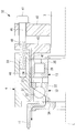
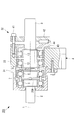
- FIG. 2 is a partially enlarged view illustrating the configuration around the input shaft of FIG.
- the input shaft 2 is a substantially cylindrical member that is rotationally driven by an external drive source, and transmits a rotational driving force to the input-side angular ball bearing 5, the output-side angular ball bearing 6, and the like.
- the input shaft 2 extends along the rotation axis L, and the output shaft 3 side (the right side in FIG. 1) is disposed inside the housing 4. Furthermore, the end of the input shaft 2 on the output shaft 3 side is disposed inside the outer ring support portion 11 of the output shaft 3.
- An output-side angular ball bearing 6 is provided between the input shaft 2 and the outer ring support portion 11, and an input-side angular ball bearing 5 is provided between the input shaft 2 and the housing 4. Further, between the output-side angular ball bearing 6 and the input-side angular ball bearing 5 in the input shaft 2, it projects radially outward from the circumferential surface of the input shaft 2, and the output-side inner ring 61 of the output-side angular ball bearing 6. And the collar part 2A which contacts the input side inner ring
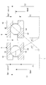
- FIG. 3 is a partially enlarged view for explaining the configuration around the output shaft of FIG.
- the output shaft 3 is a substantially cylindrical member that is rotationally driven at a rotational speed reduced by the input-side angular ball bearing 5, the output-side angular ball bearing 6, and the like.
- the output shaft 3 extends along the rotation axis L, and the input shaft 2 side (left side in FIG. 1) is disposed inside the housing 4.
- a substantially cylindrical outer ring support portion (support portion) 11 having the rotation axis L as the rotation axis, and a preload on the inner peripheral surface side of the outer ring support portion 11. Is transmitted to the output-side angular contact ball bearing 6.
- the transmission surface 11 ⁇ / b> A is a substantially ring-shaped surface extending in a direction perpendicular to the rotation axis L, and is a surface that contacts the output-side outer ring 62 of the output-side angular ball bearing 6.
- an output-side angular ball bearing 6 is provided between the outer ring support portion 11 and the input shaft 2, and between the output shaft 3 and the housing 4, as shown in FIG. 3.
- a first support bearing (third rolling bearing) 12 and a second supporting bearing (fourth rolling bearing) 13 are provided in this order from the input shaft 2 side.
- the output side outer ring 62 is provided on the inner peripheral surface of the outer ring support portion 11, and the first support inner ring 22 and the second support inner ring 25 are sequentially provided on the circumferential surface of the output shaft 3 from the input shaft 2 side. Is provided.
- the first support bearing 12 and the second support bearing 13 are bearings that are arranged side by side in the rotation axis L direction and that support the output shaft 3 so as to be rotatable around the rotation axis L. By doing so, the moment acting in the direction in which the rotation axis L of the output shaft 3 swings is received by the first support bearing 12 and the second support bearing 13, so that the output shaft 3 can be stably moved around the rotation axis L. Can be rotated.
- the first support bearing 12 is provided with a first support outer ring 21, a first support inner ring 22, and a first support rolling element 23.
- the second support bearing 13 is provided with a second support outer ring (fourth outer ring) 24, a second support inner ring 25, and a second support rolling element 26.
- the first support inner ring 22 is disposed in contact with a step portion 3A that protrudes radially outward from the output shaft 3 toward the input shaft 2 side.
- the first support outer ring 21 and the second support outer ring 24 are provided so as to be movable in a direction along the rotation axis L with respect to the housing 4.
- a second A preload ring 27 for transmitting the preload applied to the support outer ring 24 to the first support outer ring 21 is disposed.
- the first support bearing 12 is applied to an angular ball bearing
- the second support bearing 13 is applied to a cylindrical roller bearing.
- the moment acting in the direction in which the rotation axis L of the output shaft 3 swings can be received more reliably, and the output shaft 3 can be rotated around the rotation axis L stably.
- the preload is transmitted from the second support outer ring 24 to the first support bearing 12 and is transmitted from the first support bearing 12 to the output shaft 3.
- the second support bearing 13 is a roller bearing having a substantially cylindrical rolling element. Therefore, the output shaft 3 can be supported rotatably.
- the housing 4 supports the input shaft 2 and the output shaft 3 so as to be rotatable around the rotation axis L.
- the housing 4 includes a lid portion 31 in which the input side angular ball bearing 5 and the output side angular ball bearing 6 are accommodated, and a preload portion that applies preload to the input side angular ball bearing 5 and the output side angular ball bearing 6. 32 and a housing body 33 to which the lid portion 31 and the preload portion 32 are attached.
- the lid 31 is attached to the housing body 33 on the input shaft 2 side, thereby forming a cylindrical space between the lid body 31 and the formed space.
- the outer ring support portion 11, the input side angular ball bearing 5, the output side angular ball bearing 6, and the like are accommodated.
- the lid portion 31 is a bottomed cylindrical member having an opening on the output shaft 3 side, and a through hole through which the input shaft 2 is inserted is formed on the end surface on the input shaft 2 side.
- An input-side angular ball bearing 5 is provided between the lid portion 31 and the input shaft 2, and a gap is provided between the lid portion 31 and the outer ring support portion 11.
- the input-side outer ring 52 is provided on the inner peripheral surface of the lid part 31, and a gap is formed between the outer ring support part 11 and the outer ring support part 11 so as to be rotatable.
- the lid portion 31 is provided with a pressure receiving surface (pressure receiving portion) 31A that contacts the input outer ring 52 of the input side angular ball bearing 5 and receives a preload.
- the pressure receiving surface 31A is a ring-shaped stepped surface that extends radially outward toward the output shaft 3 side.
- the preload portion 32 is connected to the input-side angular ball bearing 5 and the output-side angular ball bearing 6 via the first support bearing 12, the second support bearing 13, and the output shaft 3. Preload is applied and preload is applied.
- the preload portion 32 is provided with a preload bolt 41 for generating preload, a first pressing portion 42 and a second pressing portion 43, and a load cell 44 for measuring the preload.
- the first pressing part 42 presses the first supporting outer ring 21 and the second supporting outer ring 24 together with the preload bolt 41 and the second pressing part 43 to the input shaft 2 side, and the input side angular ball bearing 5 and the output side angular ball bearing 6. It generates a preload to be applied.
- the first pressing portion 42 is a plate-like member having a hole through which the output shaft 3 is inserted, and is disposed on the output shaft 3 side (right side in FIG. 3) with respect to the second pressing portion 43.
- a first insertion hole 45 through which the preload bolt 41 is inserted is formed in the first pressing portion 42, and a load cell 44 is disposed on a surface facing the second pressing portion 43.
- the second pressing portion 43 presses the first supporting outer ring 21 and the second supporting outer ring 24 together with the preload bolt 41 and the first pressing portion 42 to the input shaft 2 side, and the input side angular ball bearing 5 and the output side angular ball bearing 6. It generates a preload to be applied.
- the second pressing portion 43 is a plate-like member having a hole through which the output shaft 3 is inserted, and is disposed between the first pressing portion 42 and the housing body 33.
- a second insertion hole 46 through which the preload bolt 41 is inserted is formed in the second pressing portion 43, and a cylindrical portion 47 that presses the second support outer ring 24 is formed on the surface facing the housing body 33. Yes.
- the load cell 44 is disposed between the first pressing portion 42 and the second pressing portion 43, and measures the preload transmitted to the input side angular ball bearing 5 and the like.
- a well-known thing can be used as the load cell 44, It does not specifically limit.
- the preload is measured using the load cell 44.
- an elastic member such as a coil spring is disposed between the preload bolt 41 and the first pressing portion 42, and the coil spring
- the preload may be measured based on the amount of compression, and is not particularly limited.
- the housing body 33 is attached with the lid portion 31 and the preload portion 32, and supports the input shaft 2 and the output shaft 3 so as to be rotatable around the rotation axis L. As shown in FIGS. 1 and 3, a bolt hole 48 into which the preload bolt 41 is screwed is formed in the housing body 33. Further, a first support bearing 12 and a second support bearing 13 are provided between the housing body 33 and the output shaft 3, and a preload ring is provided between the first support bearing 12 and the second support bearing 13. 27 is provided.
- the input-side angular ball bearing 5 is an angular ball bearing provided between the lid portion 31 and the input shaft 2, together with the output-side angular ball bearing 6 and the holding portion 7. , The rotational speed of the input shaft 2 is decelerated and transmitted to the output shaft 3.
- the input-side angular ball bearing 5 is provided with an input-side inner ring (first inner ring) 51, an input-side outer ring (first outer ring) 52, and an input-side ball (first rolling element) 53.
- the input side inner ring 51 is a ring-shaped member provided on the circumferential surface of the input shaft 2.
- an input side inner rolling surface (first inner rolling surface) 54 on which the input side ball 53 rolls is provided on the radially outer side of the input side inner ring 51.
- the input-side inner rolling surface 54 is provided with a surface that is inclined radially outward from the input shaft 2 toward the output shaft 3, in other words, a surface that receives a preload.
- the input-side outer ring 52 is a ring-shaped member provided on the inner peripheral surface of the lid portion 31, and is tightened against the inner peripheral surface of the lid portion 31, for example.
- An input side outer rolling surface (first outer rolling surface) 55 on which the input side ball 53 rolls is provided on the radially inner side of the input side outer ring 52.
- the input-side outer rolling surface 55 is provided with a surface that is inclined radially outward from the input shaft 2 toward the output shaft 3, in other words, a surface that receives a preload.
- the output-side angular ball bearing 6 is an angular ball bearing provided between the outer ring support portion 11 and the input shaft 2, and includes an input-side angular ball bearing 5 and a holding portion 7. At the same time, the rotational speed of the input shaft 2 is reduced and transmitted to the output shaft 3.
- the output side angular ball bearing 6 is provided with an output side inner ring (second inner ring) 61, an output side outer ring (second outer ring) 62, and an output side ball (second rolling element) 63.
- the output side inner ring 61 is a ring-shaped member provided on the circumferential surface of the input shaft 2, and on the radially outer side of the output side inner ring 61, the output side inner ring 63 on which the output side ball 63 rolls.
- a surface (second inner rolling surface) 64 is provided.
- the output-side inner rolling surface 64 is provided with a surface that is inclined radially inward from the input shaft 2 toward the output shaft 3, in other words, a surface that receives a preload.
- the output-side outer ring 62 is a ring-shaped member provided on the inner peripheral surface of the outer ring support part 11, and is tightened against the outer ring support part 11, for example.
- An output side outer rolling surface (second outer rolling surface) 65 on which the output side ball 63 rolls is provided on the radially inner side of the output side outer ring 62.
- the output-side outer rolling surface 65 is provided with a surface that is inclined radially inward from the input shaft 2 toward the output shaft 3, in other words, a surface that receives a preload.
- the contact angle (second contact angle) ⁇ 2 of the output side angular ball bearing 6 is about 40 °.
- the contact angle ⁇ 2 is a line connecting the contact point between the output side ball 63 and the output side inner rolling surface 64 and the contact point between the output side ball 63 and the output side outer rolling surface 65. The angle between the line and the radial plane.
- the output side angular ball bearing 6 is disposed so that the action line is inclined toward the rotation axis L toward the input shaft 2.
- the holding portion 7 is a substantially cylindrical member formed of a material such as a copper alloy, and holds the input side ball 53 and the output side ball 63.
- a copper alloy By forming the holding portion 7 using a copper alloy, the life of the holding portion 7 is increased and the torque that can be transmitted is increased as compared with the case where other materials are used.
- a resin having lubricity for example, polytetrafluoroethylene (Teflon (registered trademark)) or the like is disposed on the sliding surface of the holding unit 7 with the input side ball 53 and the output side ball 63.
- Teflon polytetrafluoroethylene
- the like is disposed on the sliding surface of the holding unit 7 with the input side ball 53 and the output side ball 63.
- the preload transmitted to the second pressing portion 43 is transmitted from the cylindrical portion 47 of the second pressing portion 43 to the first supporting outer ring 21 via the second supporting outer ring 24 and the preloading ring 27. Since the first support outer ring 21, the preload ring 27, and the second support outer ring 24 are arranged to be movable in the direction of the rotation axis L with respect to the housing body 33, the preload is transmitted to the first support outer ring 21. Is done. Further, since the second support bearing 13 is a cylindrical roller bearing, transmission of the preload is not hindered.
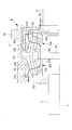
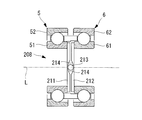
- FIG. 4 is a partially enlarged view illustrating the configuration of the input side angular contact ball bearing and the output side angular contact ball bearing in FIG. 1.
- n5 ((E2F1-E1F2) / E2 (F1 + E1)) n1 (6)
- the rotational speed ratio i between the input shaft 2 and the output shaft 3, that is, the reduction ratio i is expressed by the following equation (7) based on the above equation (6).
- various values of the rotational speed ratio i can be realized by adjusting the track diameters F1, E1, F2, and E2.
- Examples of the value of the rotational speed ratio i include values such as 2.5, 10, 50, and 100.
- by adjusting the sign of (E2F1-E1F2) in Expression (7) it is controlled whether the input shaft 2 and the output shaft 3 are rotated in the same direction or in the reverse direction.
- the orbital diameters F2 and E2 and the contact angle ⁇ 2 have the relationship of the following expressions (10) and (11).
- F2 Dpw2 + (Dw2 ⁇ cos ⁇ 2) / 2 (10)
- E2 Dpw2- (Dw2 ⁇ cos ⁇ 2) / 2 (11)
- Dpw2 is a pitch circle diameter in the output-side angular ball bearing 6
- Dw2 is a diameter of the output-side ball 63.
- the pitch circle diameters Dpw1, Dpw2, the diameter Dw1 of the input side ball 53, and the diameter Dw2 of the output side ball 63 do not change from the above formulas (8) to (11), the contact angle ⁇ 1 and the contact angle ⁇ 2 It can be seen that the values of the track diameters F1, E1 and the track diameters F2, E2 are adjusted by adjusting.
- the preload applied to the output shaft 3 from the preload portion 32 is transmitted to the output angular ball bearing 6 via the transmission surface 11A, and then the output angular ball bearing 6 and the input angular contact. It is received by the pressure receiving surface 31 ⁇ / b> A of the housing 4 through the ball bearing 5. At this time, since both the preload portion 32 and the pressure receiving surface 31A are provided in the housing 4, the preload is reliably applied to the output side angular ball bearing 6 and the input side angular ball bearing 5, and a preload sufficient for torque transmission is obtained. Can be applied.
- the input side angular contact ball bearing 6 is mounted on the outer ring support portion 11 and the input shaft 2 and the input side angular contact ball bearing 5 is mounted on the housing 4 and the input shaft 2 by a method that cannot be relatively moved, the input side angular contact ball bearing. 5 and the output-side angular ball bearing 6 are applied with sufficient preload for torque transmission, and slippage in the input-side angular ball bearing 5 and the second rolling bearing can be prevented.
- the preload applied from the preload portion 32 to the output shaft 3 is transmitted to the output side outer ring 62 of the output side angular ball bearing 6 through the transmission surface 11A.
- the preload transmitted to the output-side outer ring 62 is transmitted to the output-side inner ring 61 via the output-side outer rolling surface 65, the output-side ball 63, and the output-side inner rolling surface 64, and further to the input-side angular ball bearing. 5 to the input side inner ring 51.
- the preload transmitted to the input side inner ring 51 is transmitted to the input side outer ring 52 via the input side inner rolling surface 54, the input side ball 53 and the input side outer rolling surface 55.
- the preload transmitted to the input side outer ring 52 is received by the pressure receiving surface 31 ⁇ / b> A of the housing 4.
- a reaction force acting in the direction opposite to the preload is transmitted from the pressure receiving surface 31A to the input side inner ring 51. Therefore, the input side ball 53 is pressed in the direction compressed between the input side inner ring 51 and the input side outer ring 52. In other words, the input-side ball 53 is pressed between the input-side inner rolling surface 54 and the input-side outer rolling surface 55, and preload is applied.
- a reaction force is transmitted from the pressure receiving surface 31 ⁇ / b> A to the output side inner ring 61 via the input side angular ball bearing 5. Therefore, the output side ball 63 is pressed in the direction compressed between the output side inner ring 61 and the output side outer ring 62. In other words, the output-side ball 63 is pressed between the output-side inner rolling surface 64 and the output-side outer rolling surface 65, and preload is applied.
- the contact angle ⁇ 1 of the input side angular ball bearing 5 or the contact angle ⁇ 2 of the output side angular ball bearing 6 is adjusted to adjust the values of the respective track diameters F1, E1, F2, E2, so that substantially the same physique.
- the rotational speed ratio i can be adjusted using the input side angular contact ball bearing 5 or the output side angular contact ball bearing 6.
- the rotation speed ratio i is adjusted by adjusting the contact angle ⁇ 1 and the contact angle ⁇ 2. Can do. Furthermore, since the revolution radius of the input side ball 53 and the output side ball 63 can be made substantially equal, the holding portion 7 can be formed in a substantially cylindrical shape that can be easily formed.
- the speed device 1 can be used for acceleration / deceleration in a region where the rotational speed is high.
- the present invention is not limited to this.
- the description is applied to an example in which the rotation speed ratio i is adjusted by adjusting the contact angle ⁇ 1 and the contact angle ⁇ 2.
- the ball diameter Dw1 of the input side ball 53 and the output side are described.
- the rotational speed ratio i may be adjusted by selecting the ball diameter Dw2 of the ball 63, or the rotational speed ratio i may be adjusted by selecting the track diameter F1 or the track diameter F2, which is particularly limited. is not.
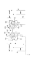
- FIG. 5 is a schematic diagram illustrating the configuration of the speed increasing / decreasing device according to the present embodiment.
- symbol is attached
- the speed increasing / decreasing device 101 is decelerated based on an input shaft 2 that is driven to rotate at a predetermined rotational speed by an external drive source (not shown) and a predetermined rotational speed ratio i.
- a bearing (first rolling bearing) 105, an output side conical roller bearing (second rolling bearing) 106, and a holding portion 107 are provided.
- FIG. 6 is a partially enlarged view for explaining the configuration of the input side conical roller bearing and the output side conical roller bearing of FIG. 5.
- the input side conical roller bearing 105 is a conical roller bearing provided between the lid portion 31 and the input shaft 2, and includes the output side conical roller bearing 106 and the holding portion 107. , The rotational speed of the input shaft 2 is decelerated and transmitted to the output shaft 3.
- the input side conical roller bearing 105 is provided with an input side inner ring (first inner ring) 151, an input side outer ring (first outer ring) 152, and an input side conical roller (first rolling element) 153.
- the input side inner ring 151 is a ring-shaped member provided on the circumferential surface of the input shaft 2, and is an inclined surface on the radially outer side of the input side inner ring 151 on which the input side conical roller 153 rolls.
- An input-side inner rolling surface (first inner rolling surface) 154 is provided.
- the input-side outer ring 152 is a ring-shaped member provided on the inner peripheral surface of the lid portion 31.
- the input-side outer ring 152 is an inclined surface on the radially inner side of the input-side outer ring 152 on which the input-side conical roller 153 rolls.
- a side outer rolling surface (first outer rolling surface) 155 is provided.
- the output side conical roller bearing 106 is a conical roller bearing provided between the outer ring support portion 11 and the input shaft 2, and includes an input side conical roller bearing 105 and a holding portion 107. At the same time, the rotational speed of the input shaft 2 is reduced and transmitted to the output shaft 3.
- the output side conical roller bearing 106 is provided with an output side inner ring (second inner ring) 161, an output side outer ring (second outer ring) 162, and an output side conical roller (second rolling element) 163.
- the output-side inner ring 161 is a ring-shaped member provided on the circumferential surface of the input shaft 2, and is an inclined surface on which the output-side conical roller 163 rolls on the radially outer side of the output-side inner ring 161.
- An output side inner rolling surface (second inner rolling surface) 164 is provided.
- the output side outer ring 162 is a ring-shaped member provided on the inner peripheral surface of the outer ring support portion 11, and is an inclined surface on the radially inner side of the output side outer ring 162 on which the output side conical roller 163 rolls.
- An output-side outer rolling surface (second outer rolling surface) 165 is provided.
- the holding unit 107 is a substantially cylindrical member, and holds the input-side cone roller 153 and the output-side cone roller 163.
- the holding portion 107 is a substantially cylindrical member extending along the rotation axis L, and the end on the input shaft 2 side is inclined toward the rotation axis L in the input shaft 2 direction (left direction in FIG. 6).
- the end portion on the output shaft 3 side has an inclined surface that approaches the rotation axis in the direction of the output shaft 3 (the right direction in FIG. 6).
- FIG. 7 is a partially enlarged view illustrating the configuration of the input side conical roller bearing and the output side conical roller bearing in FIG. 6.
- the track diameter F1 is a diameter related to a contact point between the central portion of the input-side cone roller 153 and the input-side inner rolling surface 154, and is a diameter of a circle that is a set of the contact points. is there.
- the track diameter E ⁇ b> 1 is a diameter related to a contact point between the central portion of the input side conical roller 153 and the input side outer rolling surface 155.
- the track diameter F2 is a diameter related to a contact point between the central portion of the output side conical roller 163 and the output side inner rolling surface 164, and is a diameter of a circle that is a set of the contact points.
- the track diameter E ⁇ b> 2 is a diameter related to a contact point between the center portion of the output-side conical roller 163 and the output-side outer rolling surface 165.
- Dpw1 is a pitch circle diameter at the center of the input-side cone roller 153
- Dw1 is a diameter at the center section of the input-side cone roller 153
- Dpw2 is the pitch circle diameter at the center of the output-side cone roller 163
- Dw2 is the diameter at the center section of the output-side cone roller 163.
- the speed increasing / decreasing device 101 of the present embodiment has a larger rotational torque transmission area between the input shaft 2 and the output shaft 3 than when the contact between the rolling element and the rolling surface is a point contact. Therefore, a large torque can be transmitted.
- the speed increasing / decreasing device 201 is decelerated based on an input shaft 2 that is driven to rotate at a predetermined rotational speed by an external drive source (not shown) and a predetermined rotational speed ratio i.
- An output shaft 3 that is rotated at a rotational speed
- a housing 4 that rotatably supports the input shaft 2 and the output shaft 3 around the rotation axis L, and an input side angular ball that transmits rotation from the input shaft 2 to the output shaft 3
- a bearing 5, an output-side angular ball bearing 6, and a holding unit 7, and a torque cam 208 that adjusts a preload applied to the input-side angular ball bearing 5 and the output-side angular ball bearing 6 are provided.
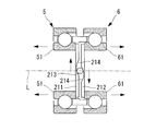
- FIG. 9 is a partially enlarged view illustrating the configuration of the torque cam of FIG.
- the torque cam 208 is disposed between the input-side angular ball bearing 5 and the output-side angular ball bearing 6, and applies a preload to the input-side angular ball bearing 5 and the output-side angular ball bearing 6.
- the torque cam 208 is provided with an input cam portion 211, an output cam portion 212, and a guide roller 213.
- the input cam portion 211 is a substantially disk-shaped member that generates a force acting in the direction along the rotation axis L together with the output cam portion 212 and the guide roller 213.
- the input cam portion 211 has a central axis substantially coincident with the rotational axis L and is disposed in contact with the input inner ring 51 of the input angular ball bearing 5.
- a guide groove 214 that contacts the guide roller 213 is formed on a surface of the input side cam portion 211 that faces the output side cam portion 212.
- the guide groove 214 is formed with an inclined surface that approaches the output side cam portion 212 from the center toward both ends.
- the output cam portion 212 is a substantially disk-shaped member that generates a force acting in the direction along the rotation axis L together with the input cam portion 211 and the guide roller 213.
- the output side cam portion 212 has a central axis substantially coincident with the rotation axis L, and is disposed in contact with the output side inner ring 61 of the output side angular ball bearing 6.
- a guide groove 214 that contacts the guide roller 213 is formed on a surface of the output side cam portion 212 that faces the output side cam portion 212.
- the guide groove 214 is formed with an inclined surface that approaches the output side cam portion 212 from the center toward both ends.
- the guide roller 213 is a roller that, together with the input side cam portion 211 and the input side cam portion 211, generates a force that acts in the direction along the rotation axis L.
- the guide roller 213 is disposed between the guide groove 214 of the input side cam portion 211 and the guide groove 214 of the input side cam portion 211, and can roll with respect to the input side cam portion 211 and the input side cam portion 211. Has been.
- FIG. 10 is a partially enlarged view for explaining a state when the preload by the torque cam of FIG. 9 is increased. Thereafter, when a torque around the rotation axis L is applied to the torque cam 208, the phase between the input side cam portion 211 and the output side cam portion 212 is shifted as shown in FIG. That is, a phase difference is generated between the guide groove 214 of the input side cam portion 211 and the guide groove 214 of the output side cam portion 212.
- the guide roller 213 rolls with respect to the input side cam portion 211 and the output side cam portion 212 and comes into contact with the inclined surface of the guide groove 214.
- the preload applied to the input side angular ball bearing 5 and the output side angular ball bearing 6 by the torque cam 208 is substantially proportional to the magnitude of the torque applied to the torque cam 208.
- the preload applied to the input-side angular ball bearing 5 and the output-side angular ball bearing 6 is automatically adjusted according to the magnitude of the value of torque applied to the speed increasing / decreasing device 201. Therefore, compared with the method of adjusting the preload applied to the input side angular contact ball bearing 5 and the output side angular contact ball bearing 6 only by the preload portion 32, the slippage and the like in the input side angular contact ball bearing 5 and the output side angular contact ball bearing 6 are ensured. Can be prevented.
- FIG. 11 is a schematic view for explaining another embodiment of the speed increasing / decreasing device of FIG.
- the example in which the torque cam 208 is applied to the speed increasing / decreasing device 201 including the input side angular ball bearing 5 and the output side angular ball bearing 6 has been described.
- the torque cam 208 may be applied to the speed increasing / decreasing device 201 provided with the roller bearing 105 and the output side conical roller bearing 106, and is not particularly limited.
- FIG. 12 is a schematic diagram illustrating the configuration of the speed increasing / decreasing device according to the present embodiment.
- symbol is attached
- the speed increasing / decreasing device 301 is decelerated based on the input shaft 2 rotated at a predetermined rotational speed by an external drive source (not shown) and a predetermined rotational speed ratio i.
- An output shaft 3 that is rotated at a rotational speed
- a housing 4 that rotatably supports the input shaft 2 and the output shaft 3 around the rotation axis L
- an input-side planetary roller that transmits rotation from the input shaft 2 to the output shaft 3
- a part 305, an output side planetary roller part 306, and a planetary pin (holding part) 307 are provided.
- FIG. 13 is a partially enlarged view illustrating the configuration of the input planetary roller unit and the output planetary roller unit of FIG.
- the input side planetary roller unit 305 is a planetary roller provided between the housing 4 and the input shaft 2, and together with the output side planetary roller unit 306 and the planetary pin 307, Some of them reduce the rotational speed of the input shaft 2 and transmit it to the output shaft 3.
- the input-side planetary roller 353 is a substantially cylindrical member that transfers between the input-side inner rolling surface 354 and the input-side outer rolling surface 355, and is connected to the output-side planetary roller 363 via the planetary pin 307. It is what.
- the output-side planetary roller portion 306 is a planetary roller provided between the outer ring support portion 11 and the input shaft 2, and includes the input-side planetary roller portion 305 and the planetary pin 307. The rotational speed of the input shaft 2 is reduced and transmitted to the output shaft 3.
- the output-side planetary roller portion 306 includes an output-side inner rolling surface (second inner rolling surface) 364 provided on the circumferential surface of the input shaft 2 and an output-side outer rolling surface (second outer rolling surface). ) 365 and an output side outer ring 362 formed with an output side planetary roller (second rolling element) 363.
- the output side inner rolling surface 164 is a surface provided on the circumferential surface of the input shaft 2 and is a surface on which the output side planetary roller 363 rolls.
- the output-side outer rolling surface 365 is a surface provided on the inner peripheral surface of the output-side outer ring 362 and is a surface on which the output-side planetary roller 363 rolls.
- the output-side outer ring 362 is disposed on the outer ring support portion 11.
- the planetary pin 307 is a substantially columnar member, and holds the input-side planetary roller 353 and the output-side planetary roller 363.
- the planetary pin 307 extends along the rotation axis L, the input planetary roller 353 is disposed at the end on the input shaft 2 side, and the output planetary roller 363 is disposed on the end on the output shaft 3 side.
- the input-side planetary roller 353 and the output-side planetary roller 363 are arranged so as to revolve around the rotation axis L together with the planetary pin 307.
- the operation of the speed increasing / decreasing device 301 having the above configuration will be described.
- a rotation transmission path from the input shaft 2 to the output shaft 3 will be described.
- the rotation of the input shaft 2 is transmitted to the input side planetary roller 353 via the input side inner rolling surface 354 of the input side planetary roller unit 305 as shown in FIGS. 12 and 13, and the input side planetary roller 353 rotates. Revolves around the axis L.
- the revolution of the input side planetary roller 353 is transmitted to the output side planetary roller 363 of the output side planetary roller unit 306 via the planetary pin 307.
- the output-side planetary roller 363 revolves around the rotation axis L, the rotation is transmitted to the output-side outer ring 362, and the rotation is transmitted from the output-side outer ring 362 to the output shaft 3 through the outer ring support portion 11.
- the orbital diameter F1 is a diameter related to a contact portion between the input-side planetary roller 353 and the input-side inner rolling surface 354, and is the diameter of the input-side inner rolling surface 354.
- the track diameter E1 is the diameter of the input-side outer rolling surface 355.
- the orbital diameter F2 is a diameter related to a contact portion between the output side planetary roller 363 and the output side inner rolling surface 364, and is a diameter of the output side inner rolling surface 364.
- the track diameter E2 is the diameter of the output side outer rolling surface 365.
- Dpw1 is the pitch circle diameter of the input planetary roller 353, and Dw1 is the diameter of the input planetary roller 353.
- Dpw2 is the pitch circle diameter of the output planetary roller 363, and Dw2 is the diameter of the output planetary roller 363.
- the pitch circle diameters of the input planetary roller 353 and the output planetary roller 363 are substantially equal.
Abstract
Description
つまり、非特許文献1に記載された構成では、アンギュラ軸受の外輪を筐体に対して軸方向に移動させることにより予圧をかけている。この構成では、外輪は筐体との間に働く摩擦力により静止しているため、出力トルクが増加すると、外輪に働く回転力が摩擦力を上回り、外輪と筐体との間で滑りが生じる(滑り率が増加する)可能性があると考えられる。 On the other hand, in the case of the traction drive (bearing diversion type speed reducer) described in
That is, in the configuration described in Non-Patent
本発明の増減速装置は、回転軸線まわりに回転可能に配置された第1回転軸と、前記回転軸線まわりに回転可能に配置され、前記第1回転軸の端部を覆う円筒状の支持部を有する第2回転軸と、前記第1回転軸および前記第2回転軸を支持する筐体と、前記第1回転軸と前記筐体との間に配置され、前記第1回転軸を回転可能に支持する第1転がり軸受と、前記支持部と前記第1回転軸との間に配置され、前記第1回転軸および前記第2回転軸を相対回転可能に支持する第2転がり軸受と、前記筐体に設けられ、前記第2回転軸を前記第1回転軸側に押圧する予圧力を付加する予圧部と、前記第2回転軸に付加された前記予圧力を、前記第2転がり軸受に伝達する前記第2回転軸の伝達部と、前記第2転がり軸受から前記第1転がり軸受に伝達された前記予圧力を受け止める前記筐体の受圧部と、を含む。 In order to achieve the above object, the present invention provides the following means.
The speed increasing / decreasing device of the present invention includes a first rotating shaft that is rotatably arranged around a rotation axis, and a cylindrical support portion that is rotatably arranged around the rotating axis and covers an end of the first rotating shaft. A second rotating shaft having a first housing, a housing supporting the first rotating shaft and the second rotating shaft, and being disposed between the first rotating shaft and the housing, the first rotating shaft being rotatable A first rolling bearing that supports the first rotating shaft, and a second rolling bearing that is disposed between the support portion and the first rotating shaft and supports the first rotating shaft and the second rotating shaft so as to be relatively rotatable, and A preload portion that is provided in a housing and applies a preload that presses the second rotation shaft toward the first rotation shaft, and the preload applied to the second rotation shaft is applied to the second rolling bearing. The transmission part of the second rotating shaft to be transmitted and the second rolling bearing to the first rolling bearing. It has been including a pressure receiving portion of the housing for receiving the preload force.
第1内輪に伝達された予圧力は、第1内側転走面、第1転動体および第1外側転送面を介して第1外輪に伝達される。第1外輪に伝達された予圧力は筐体の受圧部に受け止められる。 According to the present invention, the preload applied from the preload portion to the second rotating shaft is transmitted to the second outer ring of the second rolling bearing via the transmission portion. The preload transmitted to the second outer ring is transmitted to the second inner ring via the second outer rolling surface, the second rolling element and the second inner rolling surface, and further to the first inner ring of the first rolling bearing. Communicated.
The preload transmitted to the first inner ring is transmitted to the first outer ring via the first inner rolling surface, the first rolling element, and the first outer transfer surface. The preload transmitted to the first outer ring is received by the pressure receiving portion of the housing.
第2内輪には、第1転がり軸受を介して受圧部から反力が伝達される。そのため、第2転動体は第2内輪および第2外輪との間で圧縮される方向に押圧される。言い換えると、第2転動体は第2内側転走面および第2外側転走面の間で押圧され、予圧がかけられる。 A reaction force acting in a direction opposite to the preload is transmitted from the pressure receiving portion to the first inner ring. Therefore, the first rolling element is pressed in the direction compressed between the first inner ring and the first outer ring. In other words, the first rolling element is pressed between the first inner rolling surface and the first outer rolling surface, and preload is applied.
A reaction force is transmitted to the second inner ring from the pressure receiving portion via the first rolling bearing. Therefore, the second rolling element is pressed in the direction compressed between the second inner ring and the second outer ring. In other words, the second rolling element is pressed between the second inner rolling surface and the second outer rolling surface, and a preload is applied.
i=n1/n5
=E2(F1+F2)/(E2F1-E1F2) ・・・(1) In the above invention, the rotation speed ratio i between the rotation speed n1 of the first rotation shaft and the rotation speed n5 of the second rotation shaft is the track diameter F1 of the first inner rolling surface, the track of the first outer rolling surface. The diameter E1, the orbital diameter F2 of the second inner rolling surface, and the orbital diameter E2 of the second outer rolling surface are desirably represented by the following formula (1).
i = n1 / n5
= E2 (F1 + F2) / (E2F1-E1F2) (1)
上記発明においては、前記第2転がり軸受における第2接触角を変更することにより、前記第2内側転走面の軌道径F2、および、前記第2外側転走面の軌道径E2が調整されことが望ましい。 In the above invention, the track diameter F1 of the first inner rolling surface and the track diameter E1 of the first outer rolling surface are adjusted by changing the first contact angle in the first rolling bearing. It is desirable.
In the above invention, the track diameter F2 of the second inner rolling surface and the track diameter E2 of the second outer rolling surface are adjusted by changing the second contact angle in the second rolling bearing. Is desirable.
言い換えると、回転軸線を中心とした第1転動体および第2転動体の公転半径を略等しくしても、第1接触角または第2接触角を調節することにより、回転速度比iを調節することができる。
さらに、第1転動体および第2転動体の公転半径を略等しくできるため、保持部を、形成が比較的容易な略円筒状とすることができる。 According to the present invention, the rotation speed ratio i between the rotation speed n1 of the first rotation shaft and the rotation speed n2 of the second rotation shaft is adjusted using the first rolling bearing and the second rolling bearing having substantially the same physique. be able to.
In other words, the rotational speed ratio i is adjusted by adjusting the first contact angle or the second contact angle even if the revolution radii of the first rolling element and the second rolling element about the rotation axis are substantially equal. be able to.
Furthermore, since the revolution radius of a 1st rolling element and a 2nd rolling element can be made substantially equal, a holding | maintenance part can be made into a substantially cylindrical shape comparatively easy to form.
以下、本発明の第1の実施形態に係る増減速装置ついて図1から図4を参照して説明する。
図1は、本実施形態に係る増減速装置の構成を説明する模式図である。
本実施形態では、本発明の増減速装置1を、入力される回転駆動力の回転速度を減速する例に適用して説明するが、増速するものとしてもよく、特に限定するものではない。 [First Embodiment]
The speed increasing / decreasing apparatus according to the first embodiment of the present invention will be described below with reference to FIGS.
FIG. 1 is a schematic diagram illustrating the configuration of the speed increasing / decreasing apparatus according to the present embodiment.
In the present embodiment, the speed increasing / decreasing
入力軸2は、外部の駆動源によって回転駆動される略円柱状の部材であって、回転駆動力を入力側アンギュラ玉軸受5および出力側アンギュラ玉軸受6などに伝達するものである。
入力軸2は、図1および図2に示すように、回転軸線Lに沿って延びるとともに、その出力軸3側(図1の右側)は筐体4の内部に配置されている。さらに、入力軸2における出力軸3側の端部は、出力軸3の外輪支持部11の内側に配置されている。 FIG. 2 is a partially enlarged view illustrating the configuration around the input shaft of FIG.
The
As shown in FIGS. 1 and 2, the
言い換えると、入力軸2における出力軸3側の端部(図1の右側端部)には、左側に向かって順に、出力側アンギュラ玉軸受6の入力側内輪51と、鍔部2Aと、入力側アンギュラ玉軸受5の入力側内輪51と、が設けられている。 An output-side
In other words, at the end of the
出力軸3は、入力側アンギュラ玉軸受5や出力側アンギュラ玉軸受6などにより減速された回転速度で回転駆動される略円柱状の部材である。
出力軸3は、図1および図3に示すように、回転軸線Lに沿って延びるとともに、その入力軸2側(図1の左側)は筐体4の内部に配置されている。さらに、出力軸3における入力軸2側の端部には、回転軸線Lを回転軸線とする略円筒状の外輪支持部(支持部)11と、外輪支持部11の内周面側に予圧力を出力側アンギュラ玉軸受6に伝達する伝達面(伝達部)11Aが設けられている。
伝達面11Aは、回転軸線Lに対して垂直方向に延びる略リング状の面であり、出力側アンギュラ玉軸受6の出力側外輪62と接触する面である。 FIG. 3 is a partially enlarged view for explaining the configuration around the output shaft of FIG.
The
As shown in FIGS. 1 and 3, the
The
言い換えると、外輪支持部11の内周面には出力側外輪62が設けられ、出力軸3の円周面には、入力軸2側から順に、第1支持内輪22および第2支持内輪25が設けられている。 As shown in FIG. 2, an output-side
In other words, the output side
このようにすることで、出力軸3の回転軸線Lが振れる方向に働くモーメントは、第1支持軸受12および第2支持軸受13により受け止められるため、出力軸3を回転軸線Lまわりに安定して回転させることができる。 The first support bearing 12 and the second support bearing 13 are bearings that are arranged side by side in the rotation axis L direction and that support the
By doing so, the moment acting in the direction in which the rotation axis L of the
第1支持外輪21および第2支持外輪24は、筐体4に対して回転軸線Lに沿う方向に移動可能に設けられ、第1支持外輪21および第2支持外輪24の間には、第2支持外輪24に付加された予圧力を第1支持外輪21に伝達する予圧用リング27が配置されている。 The first support
The first support
第2支持軸受13を円筒コロ軸受に適用することで、出力軸3の回転軸線Lが振れる方向に働くモーメントをより確実に受け止めることができ、出力軸3を回転軸線Lまわりに安定して回転させることができる。
さらに、予圧力は、第2支持外輪24から第1支持軸受12に伝達され、第1支持軸受12から出力軸3に伝達される。このとき、第2支持外輪24が、第2支持軸受13の転動体に対して回転軸線L方向に相対移動しても、第2支持軸受13は、転動体が略円筒状のコロ軸受であるため出力軸3を回転可能に支持し続けることができる。 In the present embodiment, the first support bearing 12 is applied to an angular ball bearing, and the second support bearing 13 is applied to a cylindrical roller bearing.
By applying the second support bearing 13 to the cylindrical roller bearing, the moment acting in the direction in which the rotation axis L of the
Further, the preload is transmitted from the second support
筐体4には、内部に入力側アンギュラ玉軸受5および出力側アンギュラ玉軸受6等が収納される蓋部31と、入力側アンギュラ玉軸受5および出力側アンギュラ玉軸受6に予圧を与える予圧部32と、蓋部31および予圧部32が取付けられる筐体本体33と、が設けられている。 As shown in FIGS. 1 to 3, the
The
蓋部31と入力軸2との間には、入力側アンギュラ玉軸受5が設けられ、蓋部31と外輪支持部11との間には、隙間が設けられている。言い換えると、蓋部31の内周面には、入力側外輪52が設けられ、外輪支持部11との間に外輪支持部11を回転可能とする隙間が形成されている。 The
An input-side
予圧ボルト41は、第1押圧部42および第2押圧部43に形成された第1挿通孔45および第2挿通孔46に挿通され、筐体本体33のボルト孔48に螺合されるものである。 The
The
第1押圧部42は、出力軸3が挿通される孔が形成された板状の部材であって、第2押圧部43よりも出力軸3側(図3の右側)に配置されている。
第1押圧部42には、予圧ボルト41が挿通される第1挿通孔45が形成され、第2押圧部43との対向面にロードセル44が配置されている。 The first
The first
A
第2押圧部43は、出力軸3が挿通される孔が形成された板状の部材であって、第1押圧部42と筐体本体33との間に配置されている。
第2押圧部43には、予圧ボルト41が挿通される第2挿通孔46が形成され、筐体本体33との対向面には、第2支持外輪24を押圧する円筒部47が形成されている。 The second
The second
A
なお、ロードセル44としては公知のものを用いることができ、特に限定されるものではない。 The
In addition, a well-known thing can be used as the
筐体本体33には、図1および図3に示すように、予圧ボルト41が螺合されるボルト孔48が形成されている。さらに、筐体本体33と出力軸3との間には、第1支持軸受12および第2支持軸受13が設けられ、第1支持軸受12と第2支持軸受13との間には予圧用リング27が設けられている。 The
As shown in FIGS. 1 and 3, a
入力側内輪51は、入力軸2の円周面上に設けられたリング状の部材である。
入力側内輪51における径方向外側には、入力側玉53が転走する入力側内側転走面(第1内側転走面)54が設けられている。入力側内側転走面54には、入力軸2から出力軸3に向かって径方向外側に傾斜する面、言い換えると予圧力を受ける面が設けられている。 The input-side
The input side
On the radially outer side of the input side
入力側外輪52における径方向内側には、入力側玉53が転走する入力側外側転走面(第1外側転走面)55が設けられている。入力側外側転走面55には、入力軸2から出力軸3に向かって径方向外側に傾斜する面、言い換えると予圧力を受ける面が設けられている。 The input-side
An input side outer rolling surface (first outer rolling surface) 55 on which the
ここで、接触角α1は、入力側玉53と入力側内側転走面54との接触点と、入力側玉53と入力側外側転走面55との接触点とを結んだ線である作用線と、ラジアル平面とのなす角である。
入力側アンギュラ玉軸受5は、作用線が回転軸線Lに向かって出力軸3側に傾斜するように配置されている。 In the present embodiment, description will be made by applying to the case where the contact angle (first contact angle) α1 of the input side
Here, the contact angle α1 is a line that connects a contact point between the
The input-side
出力側内輪61は、入力軸2の円周面上に設けられたリング状の部材であって、出力側内輪61における径方向外側には、出力側玉63が転走する出力側内側転走面(第2内側転走面)64が設けられている。出力側内側転走面64には、入力軸2から出力軸3に向かって径方向内側に傾斜する面、言い換えると予圧力を受ける面が設けられている。 The output side
The output side
出力側外輪62における径方向内側には、出力側玉63が転走する出力側外側転走面(第2外側転走面)65が設けられている。出力側外側転走面65には、入力軸2から出力軸3に向かって径方向内側に傾斜する面、言い換えると予圧力を受ける面が設けられている。 The output-side
An output side outer rolling surface (second outer rolling surface) 65 on which the
ここで、接触角α2は、出力側玉63と出力側内側転走面64との接触点と、出力側玉63と出力側外側転走面65との接触点とを結んだ線である作用線と、ラジアル平面とのなす角である。
出力側アンギュラ玉軸受6は、作用線が回転軸線Lに向かって入力軸2側に傾斜するように配置されている。 In the present embodiment, description will be made by applying to the case where the contact angle (second contact angle) α2 of the output side
Here, the contact angle α2 is a line connecting the contact point between the
The output side
銅合金を用いて保持部7を形成することにより、他の材料を用いた場合と比較して、保持部7の寿命が長くなり、伝達できるトルクが大きくなる。 As shown in FIGS. 1 and 2, the holding
By forming the holding
まず、入力軸2から出力軸3への回転の伝達経路について説明する。
入力軸2の回転は、図1および図2に示すように、入力側アンギュラ玉軸受5の入力側内輪51を介して入力側玉53に伝達され、入力側玉53は回転軸線Lを中心として公転する。入力側玉53の公転は、保持部7を介して出力側アンギュラ玉軸受6の出力側玉63に伝達される。出力側玉63が回転軸線Lを中心として公転することにより、出力側外輪62に回転が伝達され、出力側外輪62から外輪支持部11を介して出力軸3に回転が伝達される。 Next, the operation of the speed increasing / decreasing
First, a rotation transmission path from the
1 and 2, the rotation of the
予圧を与える場合には、図1および図3に示すように、予圧ボルト41を回転させることにより、第1押圧部42に対して入力軸2側(図3の左側)に働く力、(以下、「予圧力」と表記する。)を作用させる。予圧力は、第1押圧部42からロードセル44を介して第2押圧部43に伝達され、ロードセル44によってその大きさが測定される。
このようにすることで、入力側アンギュラ玉軸受5および出力側アンギュラ玉軸受6にかかる予圧の大きさを知ることができる。 Next, a method for applying a preload to the input side
When preload is applied, as shown in FIGS. 1 and 3, by rotating the
By doing in this way, the magnitude | size of the preload concerning the input side angular
さらに、予圧力は、出力側アンギュラ玉軸受6の作用線に沿って入力軸2の鍔部2Aに伝達された後、鍔部2Aから入力側アンギュラ玉軸受5の入力側内輪51に伝達され、入力側アンギュラ玉軸受5に予圧が働くことになる。 As shown in FIGS. 1 and 2, the preload transmitted to the
Further, the preload is transmitted to the
図4は、図1における入力側アンギュラ玉軸受および出力側アンギュラ玉軸受の構成を説明する部分拡大図である。 Next, the reduction of the rotational speed in the input side angular
FIG. 4 is a partially enlarged view illustrating the configuration of the input side angular contact ball bearing and the output side angular contact ball bearing in FIG. 1.
n3=(F1・n1+E1・n2)/(F1+E1) ・・・(2)
ここで、n1は入力側内輪51の回転速度であり、n2は入力側外輪52の回転速度であり、n3は入力側玉53の公転方向の回転速度である。一方、F1は入力側内輪51の軌道径であり、E1は入力側外輪52の軌道径である(図4参照。)。
軌道径F1は、入力側内側転走面54と入力側玉53との接触点に関する直径であって、この接触点の集合である円の直径である。同様に、軌道径E1は入力側外側転走面55と入力側玉53との接触点に関する直径である。 First, the rotational speed in the revolution direction of the
n3 = (F1 · n1 + E1 · n2) / (F1 + E1) (2)
Here, n1 is the rotational speed of the input-side
The track diameter F1 is a diameter related to a contact point between the input-side inner rolling
n3=(F1・n1)/(F1+E1) ・・・(3) Since the input side
n3 = (F1 · n1) / (F1 + E1) (3)
n6=(F2・n4+E2・n5)/(F2+E2) ・・・(4)
ここで、n4は出力側内輪61の回転速度であり、n5は出力側外輪62の回転速度であり、n6は出力側玉63の公転方向の回転速度である。一方、F2は出力側内輪61の軌道径であり、E2は出力側外輪62の軌道径である(図4参照。)。
軌道径F2は、出力側内側転走面64と出力側玉63との接触点に関する直径であって、この接触点の集合である円の直径である。同様に、軌道径E2は出力側外側転走面65と出力側玉63との接触点に関する直径である。 On the other hand, the rotational speed in the revolution direction of the
n6 = (F2 · n4 + E2 · n5) / (F2 + E2) (4)
Here, n4 is the rotational speed of the output side
The track diameter F2 is a diameter related to a contact point between the output-side inner rolling
n5=((F2+E2)n6+F2・n4)/E2 ・・・(5) Therefore, the rotational speed of the output side
n5 = ((F2 + E2) n6 + F2 · n4) / E2 (5)
n5=((E2F1-E1F2)/E2(F1+E1))n1 ・・・(6) Since the input-
n5 = ((E2F1-E1F2) / E2 (F1 + E1)) n1 (6)
i=n1/n5
=E2(F1+E1)/(E2F1-E1F2) ・・・(7) The rotational speed ratio i between the
i = n1 / n5
= E2 (F1 + E1) / (E2F1-E1F2) (7)
さらに、式(7)における(E2F1-E1F2)の符号を調節することにより、入力軸2および出力軸3を同方向に回転させるか、逆方向に回転させるかが制御される。 Therefore, various values of the rotational speed ratio i can be realized by adjusting the track diameters F1, E1, F2, and E2. Examples of the value of the rotational speed ratio i include values such as 2.5, 10, 50, and 100.
Further, by adjusting the sign of (E2F1-E1F2) in Expression (7), it is controlled whether the
F1=Dpw1+(Dw1・cosα1)/2 ・・・(8)
E1=Dpw1-(Dw1・cosα1)/2 ・・・(9)
ここで、Dpw1は、入力側アンギュラ玉軸受5におけるピッチ円径であり、Dw1は、入力側玉53の直径である。 As shown in FIG. 4, each orbital diameter F1, E1 and the contact angle α1 have the relationship of the following expressions (8) and (9).
F1 = Dpw1 + (Dw1 · cos α1) / 2 (8)
E1 = Dpw1- (Dw1 · cos α1) / 2 (9)
Here, Dpw1 is the pitch circle diameter in the input-side
F2=Dpw2+(Dw2・cosα2)/2 ・・・(10)
E2=Dpw2-(Dw2・cosα2)/2 ・・・(11)
ここで、Dpw2は、出力側アンギュラ玉軸受6におけるピッチ円径であり、Dw2は、出力側玉63の直径である。 Similarly, the orbital diameters F2 and E2 and the contact angle α2 have the relationship of the following expressions (10) and (11).
F2 = Dpw2 + (Dw2 · cos α2) / 2 (10)
E2 = Dpw2- (Dw2 · cos α2) / 2 (11)
Here, Dpw2 is a pitch circle diameter in the output-side
入力側内輪51に伝達された予圧力は、入力側内側転走面54、入力側玉53および入力側外側転走面55を介して入力側外輪52に伝達される。入力側外輪52に伝達された予圧力は筐体4の受圧面31Aに受け止められる。 Specifically, the preload applied from the
The preload transmitted to the input side
出力側内輪61には、入力側アンギュラ玉軸受5を介して受圧面31Aから反力が伝達される。そのため、出力側玉63は出力側内輪61および出力側外輪62との間で圧縮される方向に押圧される。言い換えると、出力側玉63は出力側内側転走面64および出力側外側転走面65の間で押圧され、予圧がかけられる。 A reaction force acting in the direction opposite to the preload is transmitted from the
A reaction force is transmitted from the
そのため、転動体と転走面との接触が線接触である場合と比較して、入力側玉53や出力側玉63が転動する際の攪拌損失が小さくなることから、本実施形態の増減速装置1を、回転速度が高い領域おける増減速に用いることができる。 By using the input-side
Therefore, compared with the case where the contact between the rolling element and the rolling surface is a line contact, the stirring loss when the
In addition, as the specifications of the speed increasing / decreasing
次に、本発明の第2の実施形態について図5から図7を参照して説明する。
本実施形態の増減速装置の基本構成は、第1の実施形態と同様であるが、第1の実施形態とは、増減速に係る軸受の構成が異なっている。よって、本実施形態においては、図5から図7を用いて軸受周辺のみを説明し、その他の構成要素等の説明を省略する。
図5は、本実施形態に係る増減速装置の構成を説明する模式図である。
なお、第1の実施形態と同一の構成要素には、同一の符号を付してその説明を省略する。 [Second Embodiment]
Next, a second embodiment of the present invention will be described with reference to FIGS.
The basic configuration of the acceleration / deceleration device of this embodiment is the same as that of the first embodiment, but the configuration of the bearing related to acceleration / deceleration is different from that of the first embodiment. Therefore, in the present embodiment, only the periphery of the bearing will be described with reference to FIGS. 5 to 7 and description of other components will be omitted.
FIG. 5 is a schematic diagram illustrating the configuration of the speed increasing / decreasing device according to the present embodiment.
In addition, the same code | symbol is attached | subjected to the component same as 1st Embodiment, and the description is abbreviate | omitted.
入力側円すいコロ軸受105は、図5および図6に示すように、蓋部31と入力軸2との間に設けられた円すいコロ軸受であって、出力側円すいコロ軸受106および保持部107とともに、入力軸2の回転速度を減速して出力軸3に伝達するものある。 FIG. 6 is a partially enlarged view for explaining the configuration of the input side conical roller bearing and the output side conical roller bearing of FIG. 5.
As shown in FIGS. 5 and 6, the input side
入力側内輪151は、入力軸2の円周面上に設けられたリング状の部材であって、入力側内輪151における径方向外側には、入力側円すいコロ153が転走する傾斜面である入力側内側転走面(第1内側転走面)154が設けられている。
入力側外輪152は、蓋部31の内周面に設けられたリング状の部材であって、入力側外輪152における径方向内側には、入力側円すいコロ153が転走する傾斜面である入力側外側転走面(第1外側転走面)155が設けられている。 The input side
The input side
The input-side
出力側内輪161は、入力軸2の円周面上に設けられたリング状の部材であって、出力側内輪161における径方向外側には、出力側円すいコロ163が転走する傾斜面である出力側内側転走面(第2内側転走面)164が設けられている。
出力側外輪162は、外輪支持部11の内周面に設けられたリング状の部材であって、出力側外輪162における径方向内側には、出力側円すいコロ163が転走する傾斜面である出力側外側転走面(第2外側転走面)165が設けられている。 The output side
The output-side
The output side
保持部107は、回転軸線Lに沿って延びる略円筒状の部材であって、入力軸2側の端部は、入力軸2方向(図6の左方向)に向かって回転軸線Lに近づく傾斜面を有し、出力軸3側の端部は、出力軸3方向(図6の右方向)に向かって回転軸線に近づく傾斜面を有するものである。 As shown in FIGS. 5 and 6, the holding
The holding
まず、入力軸2から出力軸3への回転の伝達経路について説明する。
入力軸2の回転は、図5および図6に示すように、入力側円すいコロ軸受105の入力側内輪151を介して入力側円すいコロ153に伝達され、入力側円すいコロ153は回転軸線Lを中心として公転する。入力側円すいコロ153の公転は、保持部107を介して出力側円すいコロ軸受106の出力側円すいコロ163に伝達される。出力側円すいコロ163が回転軸線Lを中心として公転することにより、出力側外輪162に回転が伝達され、出力側外輪162から外輪支持部11を介して出力軸3に回転が伝達される。 The operation of the speed increasing / decreasing
First, a rotation transmission path from the
5 and 6, the rotation of the
図7は、図6における入力側円すいコロ軸受および出力側円すいコロ軸受の構成を説明する部分拡大図である。 Next, rotation speed reduction in the input side
FIG. 7 is a partially enlarged view illustrating the configuration of the input side conical roller bearing and the output side conical roller bearing in FIG. 6.
Dpw2は、出力側円すいコロ163の中央におけるピッチ円径であり、Dw2は、出力側円すいコロ163の中央断面における直径である。 Dpw1 is a pitch circle diameter at the center of the input-
Dpw2 is the pitch circle diameter at the center of the output-
次に、本発明の第3の実施形態について図8から図11を参照して説明する。
本実施形態の増減速装置の基本構成は、第1の実施形態と同様であるが、第1の実施形態とは、増減速に係る軸受の周辺構成が異なっている。よって、本実施形態においては、図8から図11を用いて増減速に係る軸受の周辺構成のみを説明し、その他の構成要素等の説明を省略する。
図8は、本実施形態に係る増減速装置の構成を説明する模式図である。
なお、第1の実施形態と同一の構成要素には、同一の符号を付してその説明を省略する。 [Third Embodiment]
Next, a third embodiment of the present invention will be described with reference to FIGS.
The basic configuration of the speed increasing / decreasing apparatus of this embodiment is the same as that of the first embodiment, but the peripheral configuration of the bearing related to speed increasing / decreasing is different from that of the first embodiment. Therefore, in the present embodiment, only the peripheral configuration of the bearing related to acceleration / deceleration will be described using FIGS. 8 to 11, and description of other components and the like will be omitted.
FIG. 8 is a schematic diagram illustrating the configuration of the speed increasing / decreasing device according to the present embodiment.
In addition, the same code | symbol is attached | subjected to the component same as 1st Embodiment, and the description is abbreviate | omitted.
トルクカム208は、図8および図9に示すように、入力側アンギュラ玉軸受5および出力側アンギュラ玉軸受6の間に配置され、入力側アンギュラ玉軸受5および出力側アンギュラ玉軸受6に与える予圧を調節するものである。
トルクカム208には、図9に示すように、入力側カム部211と、出力側カム部212と、ガイドコロ213と、が設けられている。 FIG. 9 is a partially enlarged view illustrating the configuration of the torque cam of FIG.
As shown in FIGS. 8 and 9, the
As shown in FIG. 9, the
入力側カム部211における出力側カム部212と対向する面には、ガイドコロ213と接触するガイド溝214が形成されている。ガイド溝214には、その中央から両端部に向かって出力側カム部212に近づく傾斜面が形成されている。 The
A
出力側カム部212における出力側カム部212と対向する面には、ガイドコロ213と接触するガイド溝214が形成されている。ガイド溝214には、その中央から両端部に向かって出力側カム部212に近づく傾斜面が形成されている。 The
A
ガイドコロ213は、入力側カム部211のガイド溝214と、入力側カム部211のガイド溝214との間に配置され、入力側カム部211および入力側カム部211に対して転動可能とされている。 The
The
トルクカム208に回転軸線Lまわりのトルクが付加されていない場合には、図9に示すように、予圧部32により予圧が与えられているため、ガイドコロ213はガイド溝214における溝深さが最も深い位置に移動する。
言い換えると、入力側カム部211と出力側カム部212とが最も接近した位置となる。 Next, a preload adjustment method using a torque cam will be described.
When the torque around the rotation axis L is not applied to the
In other words, the input
その後、トルクカム208に対して回転軸線Lまわりのトルクが付加されると、図10に示すように、入力側カム部211と出力側カム部212との間の位相がずれる。つまり、入力側カム部211のガイド溝214と、出力側カム部212のガイド溝214との間に位相差が発生する。ガイドコロ213は、入力側カム部211および出力側カム部212に対して転動し、ガイド溝214の傾斜面と接することになる。 FIG. 10 is a partially enlarged view for explaining a state when the preload by the torque cam of FIG. 9 is increased.
Thereafter, when a torque around the rotation axis L is applied to the
言い換えると、入力側カム部211には、回転軸線Lに沿って入力軸2側(図10の左側)に向かう力が働き、この力は入力側アンギュラ玉軸受5の入力側内輪51に伝達される。出力側カム部212には、回転軸線Lに沿って出力軸3側(図10の右側)に向かう力が働き、この力は出力側アンギュラ玉軸受6の出力側内輪61に伝達される。 Due to the
In other words, a force directed toward the
トルクカム208により入力側アンギュラ玉軸受5および出力側アンギュラ玉軸受6に与えられる予圧は、トルクカム208与えられるトルクの値の大きさに略比例する。 In this manner, forces in directions away from each other act on the input-side
The preload applied to the input side
なお、上述の実施形態では、入力側アンギュラ玉軸受5および出力側アンギュラ玉軸受6を備えた増減速装置201にトルクカム208を適用した例について説明したが、図11に示すように、入力側円すいコロ軸受105および出力側円すいコロ軸受106を備えた増減速装置201にトルクカム208を適用してもよく、特に限定するものではない。 FIG. 11 is a schematic view for explaining another embodiment of the speed increasing / decreasing device of FIG.
In the above-described embodiment, the example in which the
次に、本発明の第4の実施形態について図12および図13を参照して説明する。
本実施形態の増減速装置の基本構成は、第1の実施形態と同様であるが、第1の実施形態とは、複合遊星式の構成を採用している点が異なっている。よって、本実施形態においては、図12および図13を用いて異なる構成要素のみを説明し、その他の構成要素等の説明を省略する。
図12は、本実施形態に係る増減速装置の構成を説明する模式図である。
なお、第1の実施形態と同一の構成要素には、同一の符号を付してその説明を省略する。 [Fourth Embodiment]
Next, a fourth embodiment of the present invention will be described with reference to FIGS.
The basic configuration of the speed increasing / decreasing device of this embodiment is the same as that of the first embodiment, but is different from the first embodiment in that a compound planetary configuration is adopted. Therefore, in the present embodiment, only different components will be described using FIG. 12 and FIG. 13, and description of other components will be omitted.
FIG. 12 is a schematic diagram illustrating the configuration of the speed increasing / decreasing device according to the present embodiment.
In addition, the same code | symbol is attached | subjected to the component same as 1st Embodiment, and the description is abbreviate | omitted.
入力側遊星コロ部305は、図12および図13に示すように、筐体4と入力軸2との間に設けられた遊星コロであって、出力側遊星コロ部306および遊星ピン307とともに、入力軸2の回転速度を減速して出力軸3に伝達するものある。 FIG. 13 is a partially enlarged view illustrating the configuration of the input planetary roller unit and the output planetary roller unit of FIG.
As shown in FIGS. 12 and 13, the input side
遊星ピン307は回転軸線Lに沿って延び、入力軸2側の端部に入力側遊星コロ353が配置され、出力軸3側の端部に出力側遊星コロ363が配置されている。入力側遊星コロ353および出力側遊星コロ363は、遊星ピン307とともに回転軸線Lのまわりを公転可能に配置されている。 As shown in FIGS. 12 and 13, the
The
まず、入力軸2から出力軸3への回転の伝達経路について説明する。
入力軸2の回転は、図12および図13に示すように、入力側遊星コロ部305の入力側内側転走面354を介して入力側遊星コロ353に伝達され、入力側遊星コロ353は回転軸線Lを中心として公転する。入力側遊星コロ353の公転は、遊星ピン307を介して出力側遊星コロ部306の出力側遊星コロ363に伝達される。出力側遊星コロ363が回転軸線Lを中心として公転することにより、出力側外輪362に回転が伝達され、出力側外輪362から外輪支持部11を介して出力軸3に回転が伝達される。 The operation of the speed increasing / decreasing
First, a rotation transmission path from the
The rotation of the
入力側遊星コロ部305および出力側遊星コロ部306における回転速度の減速を説明する式は、第1の実施形態における説明で用いた式において、接触角α1および接触角α2がゼロである場合(α1=0,α2=0)と同様であるので、ここでは、各数値の定義についてのみ説明する。 Next, the reduction of the rotational speed in the input side
The expression for explaining the reduction of the rotational speed in the input side
Dpw2は、出力側遊星コロ363のピッチ円径であり、Dw2は、出力側遊星コロ363の直径である。ここでは、入力側遊星コロ353と出力側遊星コロ363とのピッチ円径は略等しくなっている。 Dpw1 is the pitch circle diameter of the input
Dpw2 is the pitch circle diameter of the output
2 入力軸(第1回転軸)
3 出力軸(第2回転軸)
4 筐体
5,105 入力側アンギュラ玉軸受(第1転がり軸受)
6,106 出力側アンギュラ玉軸受(第2転がり軸受)
7,107 保持部
11 外輪支持部(支持部)
11A 伝達面(伝達部)
12 第1支持軸受(第3転がり軸受)
13 第2支持軸受(第4転がり軸受)
24 第2支持外輪(第4外輪)
31A 受圧面(受圧部)
32 予圧部
51,151 入力側内輪(第1内輪)
52,152 入力側外輪(第1外輪)
53 入力側玉(第1転動体)
54,154,354 入力側内側転走面(第1内側転走面)
55,155,355 入力側外側転走面(第1外側転走面)
61,161 出力側内輪(第2内輪)
62,162 出力側外輪(第2外輪)
63 出力側玉(第2転動体)
64,164,364 出力側内側転走面(第2内側転走面)
65,165,365 出力側外側転走面(第2外側転走面)
153 入力側円すいコロ(第1転動体)
163 出力側円すいコロ(第2転動体)
307 遊星ピン(保持部)
353 入力側遊星コロ(第1転動体)
363 出力側遊星コロ(第2転動体)
L 回転軸線
α1 接触角(第1接触角)
α2 接触角(第2接触角) 1, 101, 201, 301 Booster /
3 Output shaft (second rotary shaft)
4 Housing 5,105 Input side angular contact ball bearing (first rolling bearing)
6,106 Output side angular contact ball bearing (second rolling bearing)
7,107
11A Transmission surface (transmission part)
12 1st support bearing (3rd rolling bearing)
13 Second support bearing (fourth rolling bearing)
24 Second support outer ring (fourth outer ring)
31A pressure receiving surface (pressure receiving part)
32
52,152 Input side outer ring (first outer ring)
53 Input side ball (first rolling element)
54,154,354 Input side inner rolling surface (first inner rolling surface)
55, 155, 355 Input side outer rolling surface (first outer rolling surface)
61,161 Output side inner ring (second inner ring)
62,162 Output side outer ring (second outer ring)
63 Output side ball (second rolling element)
64,164,364 Output side inner rolling surface (second inner rolling surface)
65,165,365 Output side outer rolling surface (second outer rolling surface)
153 Input side conical roller (first rolling element)
163 Output side conical roller (second rolling element)
307 Planetary pin (holding part)
353 Input side planetary roller (first rolling element)
363 Output side planetary roller (second rolling element)
L Rotation axis α1 Contact angle (first contact angle)
α2 contact angle (second contact angle)
Claims (9)
- 回転軸線まわりに回転可能に配置された第1回転軸と、
前記回転軸線まわりに回転可能に配置され、前記第1回転軸の端部を覆う円筒状の支持部を有する第2回転軸と、
前記第1回転軸および前記第2回転軸を支持する筐体と、
前記第1回転軸と前記筐体との間に配置され、前記第1回転軸を回転可能に支持する第1転がり軸受と、
前記支持部と前記第1回転軸との間に配置され、前記第1回転軸および前記第2回転軸を相対回転可能に支持する第2転がり軸受と、
前記筐体に設けられ、前記第2回転軸を前記第1回転軸側に押圧する予圧力を付加する予圧部と、
前記第2回転軸に付加された前記予圧力を、前記第2転がり軸受に伝達する前記第2回転軸の伝達部と、
前記第2転がり軸受から前記第1転がり軸受に伝達された前記予圧力を受け止める前記筐体の受圧部と、
を含む増減速装置。 A first rotation shaft arranged to be rotatable about a rotation axis;
A second rotating shaft that is arranged rotatably around the rotating axis and has a cylindrical support portion that covers an end of the first rotating shaft;
A housing that supports the first rotating shaft and the second rotating shaft;
A first rolling bearing disposed between the first rotating shaft and the housing and rotatably supporting the first rotating shaft;
A second rolling bearing disposed between the support portion and the first rotating shaft and supporting the first rotating shaft and the second rotating shaft so as to be relatively rotatable;
A preloading portion that is provided in the housing and adds a preload that presses the second rotation shaft toward the first rotation shaft;
A transmission portion of the second rotating shaft that transmits the pre-pressure applied to the second rotating shaft to the second rolling bearing;
A pressure receiving portion of the housing for receiving the pre-pressure transmitted from the second rolling bearing to the first rolling bearing;
Acceleration / deceleration device including - 前記第1転がり軸受は、
少なくとも前記第1回転軸から前記第2回転軸に向かって径方向外側に傾斜する面を有する第1内側転走面が設けられ、前記第2転がり軸受と前記予圧力が伝達可能に接続される第1内輪と、
少なくとも前記第1回転軸から前記第2回転軸に向かって径方向外側に傾斜する面を有する第1外側転走面が設けられ、前記受圧部と前記予圧力が伝達可能に接続される第1外輪と、
前記第1内側転走面および前記第1外側転走面との間を転動可能に配置された複数の第1転動体と、を含み、
前記第2転がり軸受は、
少なくとも前記第1回転軸から前記第2回転軸に向かって径方向内側に傾斜する面を有する第2外側転走面が設けられ、前記伝達部と前記予圧力が伝達可能に接続される第2外輪と、
少なくとも前記第1回転軸から前記第2回転軸に向かって径方向内側に傾斜する面を有する第2内側転走面が設けられ、前記第1転がり軸受と前記予圧力が伝達可能に接続される第2内輪と、
前記第2内側転走面および前記第2外側転走面との間を転動可能に配置された複数の第2転動体と、を含む請求項1記載の増減速装置。 The first rolling bearing is
A first inner rolling surface having at least a surface inclined radially outward from the first rotating shaft toward the second rotating shaft is provided, and is connected to the second rolling bearing so that the preload can be transmitted. A first inner ring;
A first outer rolling surface having a surface inclined at least radially outward from the first rotating shaft toward the second rotating shaft is provided, and is connected to the pressure receiving portion and the preload so as to be transmitted. Outer ring,
A plurality of first rolling elements arranged to roll between the first inner rolling surface and the first outer rolling surface,
The second rolling bearing is
A second outer rolling surface having a surface inclined at least radially inward from the first rotating shaft toward the second rotating shaft is provided, and is connected to be able to transmit the preload to the transmitting portion. Outer ring,
A second inner rolling surface having a surface inclined at least radially inward from the first rotating shaft toward the second rotating shaft is provided, and is connected to the first rolling bearing so that the preload can be transmitted. A second inner ring,
The speed increasing / decelerating device according to claim 1, further comprising: a plurality of second rolling elements arranged to roll between the second inner rolling surface and the second outer rolling surface. - 前記第1回転軸の回転速度n1と、前記第2回転軸の回転速度n5との回転速度比iは、前記第1内側転走面の軌道径F1、前記第1外側転走面の軌道径E1、前記第2内側転走面の軌道径F2および前記第2外側転走面の軌道径E2を用いて以下の式で表される請求項2記載の増減速装置。
i=n1/n5
=E2(F1+F2)/(E2F1-E1F2) The rotation speed ratio i between the rotation speed n1 of the first rotation shaft and the rotation speed n5 of the second rotation shaft is determined by the track diameter F1 of the first inner rolling surface and the track diameter of the first outer rolling surface. The speed increasing / decelerating device according to claim 2, which is expressed by the following formula using E1, the track diameter F2 of the second inner rolling surface and the track diameter E2 of the second outer rolling surface.
i = n1 / n5
= E2 (F1 + F2) / (E2F1-E1F2) - 前記第1転がり軸受における第1接触角を変更することにより、前記第1内側転走面の軌道径F1、および、前記第1外側転走面の軌道径E1が調整される請求項3記載の増減速装置。 The track diameter F1 of the first inner rolling surface and the track diameter E1 of the first outer rolling surface are adjusted by changing a first contact angle in the first rolling bearing. Booster / decelerator.
- 前記第2転がり軸受における第2接触角を変更することにより、前記第2内側転走面の軌道径F2、および、前記第2外側転走面の軌道径E2が調整される請求項3記載の増減速装置。 The track diameter F2 of the second inner rolling surface and the track diameter E2 of the second outer rolling surface are adjusted by changing a second contact angle in the second rolling bearing. Booster / decelerator.
- 前記第1転動体および前記第2転動体の少なくとも一方は略球状である請求項2から5のいずれかに記載の増減速装置。 6. The speed increasing / decelerating device according to claim 2, wherein at least one of the first rolling element and the second rolling element is substantially spherical.
- 前記第1転動体および前記第2転動体の少なくとも一方は、略円すいコロ状である請求項2から5のいずれかに記載の増減速装置。 6. The speed increasing / decelerating device according to claim 2, wherein at least one of the first rolling element and the second rolling element has a substantially conical roller shape.
- 前記第2回転軸と前記筐体との間に、前記第2回転軸を回転可能に支持する第3転がり軸受および第4転がり軸受が、前記回転軸線方向に並んで設けられている請求項1から7のいずれかに記載の増減速装置。 The 3rd rolling bearing and the 4th rolling bearing which support the said 2nd rotating shaft rotatably are provided between the said 2nd rotating shaft and the said housing | casing along with the said rotating shaft direction. To 7. The speed increasing / decreasing device according to any one of 7 to 7.
- 前記第4転がり軸受は、略円筒状の転動体を有するコロ軸受であり、
前記予圧部は、前記第4転がり軸受の第4外輪を介して前記第3転がり軸受に予圧力を付加し、
前記第3転がり軸受は、前記第2回転軸に前記予圧力を伝達する請求項8記載の増減速装置。 The fourth rolling bearing is a roller bearing having a substantially cylindrical rolling element,
The preload portion applies a preload to the third rolling bearing via a fourth outer ring of the fourth rolling bearing,
The speed increasing / decelerating device according to claim 8, wherein the third rolling bearing transmits the preload to the second rotating shaft.
Priority Applications (4)
| Application Number | Priority Date | Filing Date | Title |
|---|---|---|---|
| KR1020117002048A KR101248306B1 (en) | 2008-10-14 | 2009-10-06 | Acceleration and deceleration device |
| US13/003,724 US8672792B2 (en) | 2008-10-14 | 2009-10-06 | Speed increasing/decreasing apparatus |
| EP09820535.4A EP2336600B1 (en) | 2008-10-14 | 2009-10-06 | Friction type transmission |
| CN200980129582.0A CN102112779B (en) | 2008-10-14 | 2009-10-06 | Acceleration and deceleration device |
Applications Claiming Priority (2)
| Application Number | Priority Date | Filing Date | Title |
|---|---|---|---|
| JP2008265333A JP5138535B2 (en) | 2008-10-14 | 2008-10-14 | Booster / decelerator |
| JP2008-265333 | 2008-10-14 |
Publications (1)
| Publication Number | Publication Date |
|---|---|
| WO2010044357A1 true WO2010044357A1 (en) | 2010-04-22 |
Family
ID=42106521
Family Applications (1)
| Application Number | Title | Priority Date | Filing Date |
|---|---|---|---|
| PCT/JP2009/067409 WO2010044357A1 (en) | 2008-10-14 | 2009-10-06 | Acceleration and deceleration device |
Country Status (6)
| Country | Link |
|---|---|
| US (1) | US8672792B2 (en) |
| EP (1) | EP2336600B1 (en) |
| JP (1) | JP5138535B2 (en) |
| KR (1) | KR101248306B1 (en) |
| CN (1) | CN102112779B (en) |
| WO (1) | WO2010044357A1 (en) |
Families Citing this family (8)
| Publication number | Priority date | Publication date | Assignee | Title |
|---|---|---|---|---|
| US20130035199A1 (en) * | 2011-08-03 | 2013-02-07 | Rino Mechanical Components Inc. | Apparatus and method for transferring torque |
| KR20160105841A (en) * | 2014-01-07 | 2016-09-07 | 모드보트 피티와이 엘티디 | Transmission and components thereof |
| EP3001051A1 (en) * | 2014-09-29 | 2016-03-30 | Aktiebolaget SKF | Bearing unit for pinions |
| US10145454B2 (en) * | 2015-07-25 | 2018-12-04 | Wieslaw Julian Oledzki | Sliding friction-free gear |
| JP2017180687A (en) * | 2016-03-30 | 2017-10-05 | 株式会社 神崎高級工機製作所 | Rolling bearing-type transmission mechanism |
| US10415676B1 (en) * | 2016-10-06 | 2019-09-17 | X Development Llc | Roller traction drive |
| JP6825326B2 (en) * | 2016-11-18 | 2021-02-03 | 株式会社ジェイテクト | Planetary roller derailleur |
| CN108679180B (en) * | 2018-07-12 | 2023-11-24 | 关云龙 | Right-angle output steel ball speed reducer |
Citations (6)
| Publication number | Priority date | Publication date | Assignee | Title |
|---|---|---|---|---|
| JPS5364881U (en) * | 1976-10-29 | 1978-05-31 | ||
| JPH0454359A (en) * | 1990-06-20 | 1992-02-21 | Harmonic Drive Syst Ind Co Ltd | Friction transmission type harmonic change gear |
| US6406399B1 (en) * | 2000-07-28 | 2002-06-18 | The Timken Company | Planetary traction drive transmission |
| JP2002243011A (en) | 2001-02-16 | 2002-08-28 | Nissan Motor Co Ltd | Rolling body for traction drive |
| JP2003278866A (en) * | 2002-03-25 | 2003-10-02 | Mitsubishi Heavy Ind Ltd | Micro traction-drive |
| JP2003336705A (en) * | 2002-05-17 | 2003-11-28 | Mitsubishi Heavy Ind Ltd | Micro-traction drive |
Family Cites Families (8)
| Publication number | Priority date | Publication date | Assignee | Title |
|---|---|---|---|---|
| US3955661A (en) * | 1972-06-28 | 1976-05-11 | Lsb Industries, Inc. | Apparatus for opening and closing door members and the like |
| JPS5364881A (en) * | 1976-11-22 | 1978-06-09 | Honda Motor Co Ltd | Apparatus for producing wheels |
| CN2051318U (en) * | 1989-05-15 | 1990-01-17 | 武汉工业大学 | Rolling-bearing two-speed planetary speed-reducing machine |
| CN1080699A (en) * | 1992-06-27 | 1994-01-12 | 大连理工大学 | Differential speed reduction bearing |
| JPH0694092A (en) * | 1992-09-09 | 1994-04-05 | Hitoshi Nakamura | Speed reducer |
| JP3888482B2 (en) | 1997-05-13 | 2007-03-07 | 株式会社ハーモニック・ドライブ・システムズ | Booster / decelerator |
| US6409399B1 (en) * | 2000-12-21 | 2002-06-25 | Eastman Kodak Company | Photographic processor having a roller cam replenishment system |
| SE532061C2 (en) * | 2006-01-16 | 2009-10-13 | Gustav Rennerfelt | friction Gear |
-
2008
- 2008-10-14 JP JP2008265333A patent/JP5138535B2/en active Active
-
2009
- 2009-10-06 CN CN200980129582.0A patent/CN102112779B/en active Active
- 2009-10-06 EP EP09820535.4A patent/EP2336600B1/en active Active
- 2009-10-06 KR KR1020117002048A patent/KR101248306B1/en active IP Right Grant
- 2009-10-06 WO PCT/JP2009/067409 patent/WO2010044357A1/en active Application Filing
- 2009-10-06 US US13/003,724 patent/US8672792B2/en active Active
Patent Citations (6)
| Publication number | Priority date | Publication date | Assignee | Title |
|---|---|---|---|---|
| JPS5364881U (en) * | 1976-10-29 | 1978-05-31 | ||
| JPH0454359A (en) * | 1990-06-20 | 1992-02-21 | Harmonic Drive Syst Ind Co Ltd | Friction transmission type harmonic change gear |
| US6406399B1 (en) * | 2000-07-28 | 2002-06-18 | The Timken Company | Planetary traction drive transmission |
| JP2002243011A (en) | 2001-02-16 | 2002-08-28 | Nissan Motor Co Ltd | Rolling body for traction drive |
| JP2003278866A (en) * | 2002-03-25 | 2003-10-02 | Mitsubishi Heavy Ind Ltd | Micro traction-drive |
| JP2003336705A (en) * | 2002-05-17 | 2003-11-28 | Mitsubishi Heavy Ind Ltd | Micro-traction drive |
Non-Patent Citations (2)
| Title |
|---|
| MASAHITO NIWA; HIROAKI SEKI; YOSHITSUGU KAMIYA; MASATOSHI HIKIZU: "yusei kikou wo riyou shita jikuuke tenyougata gensokuki", PROCEEDINGS OF 2007 SPRING MEETING OF THE JAPAN SOCIETY OF PRECISION ENGINEERING, 2007, pages 979 - 980 |
| See also references of EP2336600A4 |
Also Published As
| Publication number | Publication date |
|---|---|
| CN102112779A (en) | 2011-06-29 |
| JP2010096209A (en) | 2010-04-30 |
| EP2336600A4 (en) | 2012-07-04 |
| KR20110031356A (en) | 2011-03-25 |
| US20110136619A1 (en) | 2011-06-09 |
| US8672792B2 (en) | 2014-03-18 |
| EP2336600B1 (en) | 2013-12-11 |
| JP5138535B2 (en) | 2013-02-06 |
| CN102112779B (en) | 2014-11-05 |
| EP2336600A1 (en) | 2011-06-22 |
| KR101248306B1 (en) | 2013-03-27 |
Similar Documents
| Publication | Publication Date | Title |
|---|---|---|
| JP5138535B2 (en) | Booster / decelerator | |
| JP4215508B2 (en) | Planetary wheel and its use | |
| JPWO2011067814A1 (en) | Continuously variable transmission | |
| JP7207628B2 (en) | transmission | |
| US8517881B2 (en) | Micro-traction drive | |
| JP3692330B2 (en) | Micro traction drive | |
| JP3617645B2 (en) | Micro traction drive | |
| JP2020094668A (en) | Friction transmission-type reduction gear | |
| CN105084181B (en) | Planetary roller reductor and use its elevator | |
| KR100991515B1 (en) | Roll down ball type high speed reducer | |
| JP7274079B2 (en) | Roller type differential reducer | |
| JP2014015975A (en) | Planetary roller type power transmission device | |
| US20230405805A1 (en) | Internally Meshing Planetary Gear Apparatus and Joint Apparatus for Robot | |
| US20230398682A1 (en) | Internally Engaged Planetary Gear Device and Robot Joint Device | |
| JP4576263B2 (en) | Traction drive device | |
| JP2016200218A (en) | Planetary roller type power transmission device | |
| JP2021001648A (en) | Multi-stage planetary roller type power transmission device | |
| JP2019210943A (en) | Transmission with electric motor and bogie drive unit | |
| JPH06280953A (en) | Traction transmission device with variable preload | |
| JP2007071350A (en) | Continuously variable transmission | |
| JP2004100927A (en) | Transmission | |
| CS227848B1 (en) | Drive conversion equipment | |
| JP2000257684A (en) | Frictional transmission | |
| JP2008008477A (en) | Planetary roller transmission | |
| JP2006002881A (en) | Power transmission device |
Legal Events
| Date | Code | Title | Description |
|---|---|---|---|
| WWE | Wipo information: entry into national phase |
Ref document number: 200980129582.0 Country of ref document: CN |
|
| 121 | Ep: the epo has been informed by wipo that ep was designated in this application |
Ref document number: 09820535 Country of ref document: EP Kind code of ref document: A1 |
|
| WWE | Wipo information: entry into national phase |
Ref document number: 13003724 Country of ref document: US |
|
| WWE | Wipo information: entry into national phase |
Ref document number: 2009820535 Country of ref document: EP |
|
| ENP | Entry into the national phase |
Ref document number: 20117002048 Country of ref document: KR Kind code of ref document: A |
|
| NENP | Non-entry into the national phase |
Ref country code: DE |