WO2010044262A1 - Wideband antenna - Google Patents
Wideband antenna Download PDFInfo
- Publication number
- WO2010044262A1 WO2010044262A1 PCT/JP2009/005360 JP2009005360W WO2010044262A1 WO 2010044262 A1 WO2010044262 A1 WO 2010044262A1 JP 2009005360 W JP2009005360 W JP 2009005360W WO 2010044262 A1 WO2010044262 A1 WO 2010044262A1
- Authority
- WO
- WIPO (PCT)
- Prior art keywords
- antenna
- antenna element
- leg
- axis
- symmetry
- Prior art date
Links
Images


Classifications
-
- H—ELECTRICITY
- H01—ELECTRIC ELEMENTS
- H01Q—ANTENNAS, i.e. RADIO AERIALS
- H01Q1/00—Details of, or arrangements associated with, antennas
- H01Q1/12—Supports; Mounting means
- H01Q1/1271—Supports; Mounting means for mounting on windscreens
-
- H—ELECTRICITY
- H01—ELECTRIC ELEMENTS
- H01Q—ANTENNAS, i.e. RADIO AERIALS
- H01Q1/00—Details of, or arrangements associated with, antennas
- H01Q1/27—Adaptation for use in or on movable bodies
- H01Q1/32—Adaptation for use in or on road or rail vehicles
- H01Q1/325—Adaptation for use in or on road or rail vehicles characterised by the location of the antenna on the vehicle
- H01Q1/3291—Adaptation for use in or on road or rail vehicles characterised by the location of the antenna on the vehicle mounted in or on other locations inside the vehicle or vehicle body
-
- H—ELECTRICITY
- H01—ELECTRIC ELEMENTS
- H01Q—ANTENNAS, i.e. RADIO AERIALS
- H01Q9/00—Electrically-short antennas having dimensions not more than twice the operating wavelength and consisting of conductive active radiating elements
- H01Q9/04—Resonant antennas
- H01Q9/16—Resonant antennas with feed intermediate between the extremities of the antenna, e.g. centre-fed dipole
- H01Q9/28—Conical, cylindrical, cage, strip, gauze, or like elements having an extended radiating surface; Elements comprising two conical surfaces having collinear axes and adjacent apices and fed by two-conductor transmission lines
- H01Q9/285—Planar dipole
Definitions
- the present invention relates to a broadband antenna.
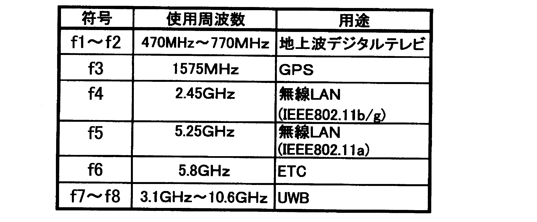
- a plurality of different target frequencies such as AM / FM radio, VICS (Vehicle Information and Communication System), GPS, TV (VHF / UHF band), ETC (Electronic Toll Collection System), etc. It was necessary to install the antenna inside or outside the car.
- VICS Vehicle Information and Communication System
- GPS GPS
- TV VHF / UHF band
- ETC Electronic Toll Collection System
- antennas are desirably arranged as compact as possible. However, when the antennas are brought close to each other, the antennas interfere with each other by electromagnetic coupling. Due to the influence of this interference, these antennas may not function normally. Therefore, in order to avoid interference between antennas, it is necessary to consider an appropriate interval and layout for each antenna.
- the antenna and related equipment are connected by a cable. For this reason, when a plurality of wireless devices using different antennas coexist, there is a problem that the cable handling becomes complicated.
- the corners of the planar antenna elements having corners such as two rhombuses, squares, rectangles, and the like are placed close to each other and arranged symmetrically. Connect the cable so that the corner is the feeding point. The other end of this cable is connected to an electronic circuit such as a receiver.
- the frequency band that realizes a return loss of ⁇ 10 dB or less (corresponding to a voltage standing wave ratio of 2.0 or less) generally required for an antenna covers up to 470 MHz of terrestrial digital television. Experiments have shown that it is not wide enough.
- FIG. 6A is a front view of an antenna 40A having a square (25 mm square) antenna element 30 having a side of 25 mm.
- FIG. 6B is a front view of an antenna 40B having a square (50 mm square) antenna element 30 having a side of 50 mm.
- the two square thin metal plates constituting the antenna elements 30 and 30 are arranged symmetrically with respect to the straight line 31.
- the corner portions 32 and 32 of the antenna elements 30 and 30 are arranged close to each other.
- the strip-shaped leg portions 33 and the flanges 33 extend in parallel from the corner portions 32 and the flanges 32 so as to form a minute gap K along the straight line 31.
- a lead wire 35 is connected to the outer end 33 a of the leg portion 33. In other words, the outer end 33a functions as a feeding point Q.
- Cable 36 connects antenna 40A to associated electronic circuitry (such as a receiver).
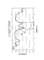
- FIG. 7 is a graph showing the actual measurement results of the return loss amounts of the antennas 40A and 40B shown in FIGS. 6A and 6B, respectively.
- the horizontal axis indicates the frequency (GHz), and the vertical axis indicates the return loss (dB).
- the frequency bands WA and WB in which the return loss of ⁇ 10 dB or less can be obtained are narrow and lack practicality.
- An object of the present invention is to provide a wideband antenna with a simple shape and structure that can provide a sufficiently practical return loss as an antenna in a frequency band sufficiently wider than the conventional frequency band.
- another object of the antenna according to the present invention is to integrate many antennas required for each of a plurality of wireless communication systems as in the prior art. Furthermore, this invention aims at simplifying wiring of a complicated cable by this integration.
- the broadband antenna of the present invention includes a pair of flat and conductive antenna elements and a pair of flat and conductive strip-shaped feeding legs, and the antenna elements are arranged in line symmetry with respect to the symmetry axis.
- the belt-like feeding legs are arranged in line symmetry with respect to the symmetry axis with a minute gap between them, and the belt-like feeding legs are connected to the antenna element in the adjacent parts where the antenna elements are closest to each other.
- the width of each of the connected belt-shaped power supply legs increases as the distance from the connection increases.
- an outer edge portion farthest from the connection portion of the antenna element forms a part of an arc
- the adjacent portion includes a part of a virtual arc
- the adjacent portion includes A joint portion is formed by joining the leg portion to the antenna element along a tangential direction in contact with a virtual arc.
- the antenna element forms a closed ring having a window at the center.
- the antenna element is substantially elliptical, and an angle at which the major axis of the ellipse intersects the symmetry axis is 40 ° to 100 °.
- the angle at which the major axis of the ellipse intersects the symmetry axis is about 90 °.
- the antenna element and the leg can be seen through with the naked eye by having a visible light transmittance of 70% to 95%.
- the antenna element and the leg are provided on a glass surface of an automobile.
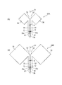
- FIG. 1 is a front view showing a first embodiment of the present invention.
- FIG. 2 is a front view showing a second embodiment of the present invention.
- FIG. 3 is a graph showing the actual measurement results of the embodiment corresponding to FIG. 1 of the present invention.
- FIG. 4 is a front view showing a third embodiment of the present invention.
- FIG. 5 is a front view showing a fourth embodiment of the present invention.
- 6A is a front view showing a conventional antenna having a 25 mm square element
- FIG. 6B is a front view showing a conventional antenna having a 50 mm square element.
- FIG. 7 is a graph showing the measurement results of the conventional example.
- FIG. 1 is a front view of a first embodiment according to the present invention.
- FIG. 2 is a front view of a second embodiment according to the present invention.
- the pair of flat and conductive antenna elements 1 and 1 are arranged symmetrically with respect to a straight line L that is an axis of line symmetry.
- a pair of flat and conductive belt-like feed legs 2, 2 protrude from adjacent portions 5, 5 of the antenna elements 1, 1.
- the antenna elements 1 and 1 and the leg portions 2 and 2 are integrally formed.
- the pair of leg portions 2 and 2 are arranged symmetrically with respect to the straight line L, are adjacent to each other, and have a minute gap G therebetween.
- the feeding legs 2 and 2 are connected to the antenna elements 1 and 1 at adjacent portions where the antenna elements 1 and 1 are closest to each other.
- each of the leg portions 2 and 2 gradually increases in the width dimension W along the outer end direction C, that is, along the direction away from the connection portion S.
- the leg portion 2 and the antenna element 1 having a shape spreading outward are configured by a single metal thin plate.
- the antenna element 1 and the leg portion 2 are made of a metal thin plate (metal foil) such as Cu, Al, Ag, Au or the like having a thickness dimension T (not shown) of 100 ⁇ m or less or a metal oxide film (ITO or It can be realized by stretching it on a glass or an electronic substrate.
- the antenna elements 1, 1 and the legs 2, 2 can be seen through with the human eye, particularly when the visible light transmittance is set to 70% to 95%. Therefore, the antenna elements 1 and 1 and the legs 2 and 2 can be realized by a mesh-type or extremely thin (for example, 0.05 ⁇ m) metal thin film or metal oxide film.
- an adhesive or an adhesive may be applied on the glass.
- the antenna elements 1, 1 and the leg portions 2, 2 may be baked and laminated on glass.
- the antenna elements 1, 1 and the legs 2, 2 are sandwiched between glass layers and fixed. All these cases are within the scope of the present invention.
- the minute gap G between the pair of leg portions 2 and 2 is formed in a tapered shape that gradually increases from the outer end 2A side toward the proximity portion 5 side of the antenna element 1. In other words, the minute gap G gradually decreases in the outer end direction C from the proximity portion 5 side.
- the shape of the antenna element 1 is substantially elliptical, but in FIG. 1, a substantially elliptical window portion 3 having a similar shape is formed in the central region, forming a closed ring. In FIG. 2, this window 3 does not exist.
- Cable 6 couples the antenna to an electronic circuit (such as an amplifier or filter).
- the cable 6 is connected to the outer end 2 ⁇ / b> A of the leg 2 at a feeding point E by a conducting wire (that is, a lead wire) 7.
- the feeding point E is preferably provided at a position close to the minute gap G, that is, at the corners of the legs 2 and 2.
- the outer end 8 of the leg 2 is formed in a concave arc shape with a large radius of curvature.
- the outermost end 10 farthest from the adjacent portion 5 of the antenna element 1 has a smooth arc shape, and the adjacent portion 5 also has a smooth arc shape.
- the outer shape of the antenna element 1 is substantially elliptical, it can be said that the outermost end portion 10 and the adjacent portion 5 are also formed in an arc shape.
- a junction S (indicated by a dotted line) is formed.
- the antenna element 1 is substantially elliptical, and the angle ⁇ at which the major axis L1 intersects the symmetry axis L is 90 °. Therefore, the leg portion 2 is joined to the adjacent portion 5 of the antenna element 1 from the direction orthogonal to the long axis L1 to form a smooth joined portion S.
- the length of the arc of the joint S is sufficiently larger than the minimum value of the width W of the leg 2.
- the antenna element 1 has a substantially elliptical outer shape, which is the same as that of the above-described embodiment.
- the embodiment of FIGS. 4 and 5 differs from the first and second embodiments shown in FIGS. 1 and 2 in that the angle ⁇ at which the major axis L1 intersects the straight line L is 45 °.
- the angle formed between the straight line L extending from the outer end 2A side of the leg 2 toward the antenna element 1 and the long axis L1 is represented by ⁇ , 40 ° ⁇ ⁇ ⁇ 100 ° is set. It is preferable that when ⁇ is less than the lower limit value or exceeds the upper limit value, the characteristics in the low frequency region are drastically deteriorated in any case.
- each leg 2 is substantially a low triangle whose width W suddenly increases as it goes in the outer end direction C.
- 4 and 5 are the same as those shown in FIGS. 1 and 2 except for those described above. 4 and 5, the adjacent portion 5 and the outermost end portion 10 are located away from the long axis L1, but have an arc shape, that is, a shape having no corners, which is the same as in FIGS. is there.
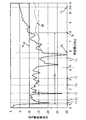
- the graph shown in FIG. 3 shows the actually measured frequency characteristics of the embodiment shown in FIG.
- the horizontal axis represents frequency (GHz), and the vertical axis represents return loss (dB).
- the material is Cu
- the thickness dimension is 35 ⁇ m
- the length dimension along the major axis L1 of the antenna element 1 is 100 mm
- the minor axis dimension is 70 mm
- Dimension is 70mm
- minor axis dimension is 40mm
- S3 / S0 33%
- distance from major axis L1 to outer end 2A of leg 2 is 50mm
- side length of outer end 2A is 35mm
- curvature of outer end 8 The radius is 50 mm
- the value near the outer end 2A of the minute gap G is 0.5 mm.
- the present invention realizes a single integrated broadband antenna that covers terrestrial digital television, GPS, wireless LAN, ETC, and the like.
- the broadband antenna of the present invention is attached to a windshield of an automobile, it is extremely useful.
- the graph of FIG. 7 showing the conventional example it can be seen how the graph of FIG. 3 showing the embodiment of the present invention covers a wide frequency band.
- an antenna having a broadband characteristic that can be applied to UWB communication as indicated by a two-dot chain line M in FIG.
- the pair of thin-sided antenna elements 1 and 1 are arranged symmetrically with respect to the straight line L.
- a pair of planar feed legs 2 and 2 are formed so as to project from the mutually adjacent portions 5 and 5 of the antenna elements 1 and 1 so as to be close to each other with a minute gap G as being symmetrical with respect to the straight line L.
- each of the legs 2 and 2 has an outwardly widened shape in which the width dimension W gradually increases in the outer end direction C. Therefore, the legs 2 and 2 constitute a broadband impedance matching circuit whose characteristic impedance gradually changes. As a result, a sufficiently wide frequency band can be handled, and the antennas of a plurality of wireless communication systems can be integrated.
- the outermost end portion 10 farthest from the adjacent portion 5 of the antenna element 1 has a smooth circular arc shape, and the adjacent portion 5 of the antenna element 1 has a smooth circular arc shape in the circular arc virtual arc. Since the leg portion 2 is joined to form the joined portion S from the tangential direction in contact with each other, only a part of the return loss curve below the ⁇ 10 dB line is steep as illustrated in FIG. Draws a mountain and does not show the characteristic of penetrating above the -10 dB line. Therefore, a stable reflection attenuation characteristic is shown in a wide frequency band.
- the antenna element 1 has a closed ring shape in which the window portion 3 is formed in the central region, and thus exhibits excellent reflection attenuation characteristics in a wide frequency band.
- the antenna element 1 is substantially elliptical, and the angle ⁇ at which the major axis L1 intersects the straight line L is set to 40 ° to 100 °. Therefore, the antenna element 1 has a simple shape and is stable. Excellent return loss characteristics over a wide frequency band.
- the antenna element 1 is substantially elliptical, and has a simple configuration with a configuration in which the angle ⁇ is about 90 ° and the major axis L1 is arranged so as to be orthogonal to the straight line L. It has an excellent reflection attenuation characteristic in a very wide frequency band with a simple shape, and can be applied to communications that require a very wide frequency band such as UWB communications.
- the antenna elements 1 and 1 and the legs 2 and 2 have a visible light transmittance of 70% to 95%, and can be seen through with the naked eye. Therefore, it can be stretched and used on transparent glass surfaces such as automobiles and windows.
- the antenna is stretched on the glass surface of the automobile, even if the antenna is made of a thin metal piece (foil), the antenna is sufficiently reinforced and durability is obtained.
- various communication essential for automobiles such as ETC, GPS, and wireless LAN can be realized by an inconspicuous antenna.
- the present invention is useful in that an antenna having an excellent frequency in a wide band can be provided.
Abstract
Description
0%≦S3/S0≦35% --(1) In FIG. 1, when the area of the
0% ≦ S3 / S0 ≦ 35% --- (1)
(fH-fL)/f0≧1.0 --(2) As can be seen from FIG. 3, the frequency band Wc showing the attenuation (dB) below the −10 dB line N −10 is sufficiently wide. That is, a return loss of −10 dB or less of the line N −10 was obtained in a wide band from the frequency f L to the high frequency f H. Specifically, f L = 0.4 GHz and f H = 7.9 GHz. Assuming that the center frequency (ie, average frequency) of both is f 0 , in the present invention, a case where the following
(F H −f L ) / f 0 ≧ 1.0 −− (2)
2 脚部
2A 外端
5 隣接部
10 最外端部
C 外端方向
G 微小間隙
L 対称軸
L1 長軸
S 接合部
θ 角度 DESCRIPTION OF
Claims (7)
- 平坦で導電性を有する1対のアンテナ素子と、
平坦で導電性を有する1対の帯状給電脚部と
を備える広帯域アンテナであって、
前記アンテナ素子は、対称軸について線対称に配置され、
前記帯状給電脚部は、互いの間に微小間隙を有して、前記対称軸について線対称に配置され、
前記帯状給電脚部は、前記アンテナ素子が互いに最も近づく隣接部において前記アンテナ素子に接続され、
前記帯状給電脚部のそれぞれの幅は、前記接続部から遠くなるにつれて大きくなる
広帯域アンテナ。 A pair of flat and conductive antenna elements;
A broadband antenna comprising a pair of flat and conductive strip-like feed legs,
The antenna elements are arranged line-symmetrically with respect to an axis of symmetry;
The belt-shaped feeding legs are arranged in line symmetry with respect to the symmetry axis, with a minute gap between them.
The belt-shaped feeding leg is connected to the antenna element at an adjacent portion where the antenna elements are closest to each other,
A wide band antenna in which the width of each of the belt-shaped feeding legs increases as the distance from the connecting portion increases. - 前記アンテナ素子の前記接続部から最も離れた外縁部は、円弧の一部を構成し、
前記隣接部は、仮想的な円弧の一部を含み、
前記隣接部における前記仮想的な円弧に接する接線方向に沿って、前記脚部が前記アンテナ素子に接合されることによって、接合部が形成される請求項1に記載の広帯域アンテナ。 The outer edge part farthest from the connection part of the antenna element constitutes a part of an arc,
The adjacent portion includes a part of a virtual arc,
The broadband antenna according to claim 1, wherein a joint portion is formed by joining the leg portion to the antenna element along a tangential direction in contact with the virtual arc in the adjacent portion. - 前記アンテナ素子は、中央に窓部を有する閉じた円環をなす請求項1に記載の広帯域アンテナ。 The broadband antenna according to claim 1, wherein the antenna element forms a closed ring having a window portion at a center.
- 前記アンテナ素子は、実質的に楕円形であり、
前記楕円の長軸が前記対称軸と交わる角度は、40°~100°である請求項1に記載の広帯域アンテナ。 The antenna element is substantially elliptical;
The broadband antenna according to claim 1, wherein an angle at which the major axis of the ellipse intersects the axis of symmetry is 40 ° to 100 °. - 前記楕円の長軸が前記対称軸と交わる角度は、約90°である請求項4に記載の広帯域アンテナ。 The wide-band antenna according to claim 4, wherein an angle at which the major axis of the ellipse intersects the axis of symmetry is about 90 °.
- 前記アンテナ素子および前記脚部は、可視光線の透過率が70%~95%であることによって、肉眼で透視可能である請求項1に記載の広帯域アンテナ。 The wide-band antenna according to claim 1, wherein the antenna element and the leg portion are visible with the naked eye when the visible light transmittance is 70% to 95%.
- 前記アンテナ素子および前記脚部は、自動車のガラス面上に設けられる請求項1に記載の広帯域アンテナ。 The broadband antenna according to claim 1, wherein the antenna element and the leg are provided on a glass surface of an automobile.
Priority Applications (3)
| Application Number | Priority Date | Filing Date | Title |
|---|---|---|---|
| CN200980138600.1A CN102171890B (en) | 2008-10-17 | 2009-10-14 | Wideband antenna |
| EP09820440.7A EP2352205A4 (en) | 2008-10-17 | 2009-10-14 | Wideband antenna |
| US13/124,267 US8599079B2 (en) | 2008-10-17 | 2009-10-14 | Wideband antenna |
Applications Claiming Priority (2)
| Application Number | Priority Date | Filing Date | Title |
|---|---|---|---|
| JP2008-268242 | 2008-10-17 | ||
| JP2008268242A JP4394732B1 (en) | 2008-10-17 | 2008-10-17 | Broadband antenna |
Publications (1)
| Publication Number | Publication Date |
|---|---|
| WO2010044262A1 true WO2010044262A1 (en) | 2010-04-22 |
Family
ID=41591542
Family Applications (1)
| Application Number | Title | Priority Date | Filing Date |
|---|---|---|---|
| PCT/JP2009/005360 WO2010044262A1 (en) | 2008-10-17 | 2009-10-14 | Wideband antenna |
Country Status (7)
| Country | Link |
|---|---|
| US (1) | US8599079B2 (en) |
| EP (1) | EP2352205A4 (en) |
| JP (1) | JP4394732B1 (en) |
| KR (1) | KR101616592B1 (en) |
| CN (1) | CN102171890B (en) |
| TW (1) | TWI524597B (en) |
| WO (1) | WO2010044262A1 (en) |
Cited By (1)
| Publication number | Priority date | Publication date | Assignee | Title |
|---|---|---|---|---|
| CN101982901A (en) * | 2010-09-29 | 2011-03-02 | 厦门大学 | Elliptical double-sided dipole antenna for vehicle-mounted digital television |
Families Citing this family (16)
| Publication number | Priority date | Publication date | Assignee | Title |
|---|---|---|---|---|
| JP4922339B2 (en) * | 2009-04-17 | 2012-04-25 | 三菱電線工業株式会社 | Broadband antenna |
| JP2012244267A (en) * | 2011-05-17 | 2012-12-10 | Mitsubishi Cable Ind Ltd | Antenna |
| CN102694253B (en) * | 2012-06-11 | 2014-02-12 | 哈尔滨工业大学 | Balance microstrip line feed ultra-wideband dipole antenna |
| KR101574495B1 (en) * | 2013-08-13 | 2015-12-04 | 주식회사 에이스테크놀로지 | Wideband Base Station Antenna Radiator |
| US9954280B1 (en) * | 2013-09-19 | 2018-04-24 | Mano D. Judd | Dipole antenna with parasitic elements |
| CN103579768B (en) * | 2013-11-07 | 2015-06-03 | 中国计量学院 | Bean-sprout-shaped single-frequency narrow-band micro-strip antenna |
| USD849722S1 (en) * | 2017-05-22 | 2019-05-28 | Shenzhen Antop Technology Limited | Antenna |
| USD847798S1 (en) * | 2017-05-22 | 2019-05-07 | Shenzhen Antop Technology Limited | Antenna |
| USD872712S1 (en) * | 2017-05-22 | 2020-01-14 | Shenzhen Antop Technology Limited | Antenna |
| USD850425S1 (en) * | 2017-05-22 | 2019-06-04 | Shenzhen Antop Technology Limited | Antenna |
| US11271303B2 (en) * | 2019-01-03 | 2022-03-08 | Boe Technology Group Co., Ltd. | Antenna, smart window, and method of fabricating antenna |
| USD909999S1 (en) * | 2019-08-16 | 2021-02-09 | Zhicheng Zhou | TV antenna |
| USD910606S1 (en) * | 2019-08-20 | 2021-02-16 | Zhicheng Zhou | TV antenna |
| USD956726S1 (en) * | 2019-10-12 | 2022-07-05 | Shenzhen Antop Technology Co. Ltd. | Antenna |
| USD956724S1 (en) * | 2019-10-12 | 2022-07-05 | Shenzhen Antop Technology Co. Ltd. | Antenna |
| USD956725S1 (en) * | 2019-10-12 | 2022-07-05 | Shenzhen Antop Technology Co. Ltd. | Antenna |
Citations (8)
| Publication number | Priority date | Publication date | Assignee | Title |
|---|---|---|---|---|
| JPS554109A (en) * | 1978-06-23 | 1980-01-12 | Enu Isumeiru Fuaami Musutaafua | Elliptical antenna of sheet shape for wide band |
| JPH088628A (en) * | 1994-06-22 | 1996-01-12 | Kubota Corp | Antenna |
| US20030090436A1 (en) * | 2001-11-13 | 2003-05-15 | Schantz Hans G. | Ultra wideband antenna having frequency selectivity |
| JP2005130292A (en) * | 2003-10-24 | 2005-05-19 | Ykc:Kk | Ultra-wideband antenna and ultra-wideband high-frequency module |
| JP2005277501A (en) | 2004-03-23 | 2005-10-06 | Amplet:Kk | Uwb antenna |
| JP2005539417A (en) * | 2002-07-15 | 2005-12-22 | フラクトゥス・ソシエダッド・アノニマ | Antenna with one or more holes |
| JP2007243908A (en) * | 2005-09-29 | 2007-09-20 | Matsushita Electric Ind Co Ltd | Antenna device and electronic apparatus using the same |
| US20080252543A1 (en) * | 2007-04-11 | 2008-10-16 | Vubiq, Incorporated, A Nevada Corporation | Full-wave di-patch antenna |
Family Cites Families (14)
| Publication number | Priority date | Publication date | Assignee | Title |
|---|---|---|---|---|
| JP2845334B2 (en) | 1990-01-29 | 1999-01-13 | 日本電信電話株式会社 | Invisible object detection antenna |
| JPH06268433A (en) | 1991-07-31 | 1994-09-22 | Mitsubishi Electric Corp | Printed dipole antenna with reflecting board |
| US5774859A (en) * | 1995-01-03 | 1998-06-30 | Scientific-Atlanta, Inc. | Information system having a speech interface |
| US20050231426A1 (en) * | 2004-02-02 | 2005-10-20 | Nathan Cohen | Transparent wideband antenna system |
| DE19734595A1 (en) | 1997-08-09 | 1999-02-11 | Bosch Gmbh Robert | Procedure for determining segment times |
| FR2779276B1 (en) | 1998-05-28 | 2000-07-13 | Alsthom Cge Alcatel | RADIO COMMUNICATION DEVICE AND LOOP SLOT ANTENNA |
| JP2002139737A (en) | 2000-07-31 | 2002-05-17 | Matsushita Electric Ind Co Ltd | Liquid crystal display device and its manufacturing method |
| EP1542314A1 (en) * | 2003-12-11 | 2005-06-15 | Sony International (Europe) GmbH | Three-dimensional omni-directional monopole antenna designs for ultra- wideband applications |
| TW200644333A (en) * | 2005-06-03 | 2006-12-16 | Coretronic Corp | Ultra-wideband directional antenna |
| US7365693B2 (en) | 2005-09-29 | 2008-04-29 | Matsushita Electric Industrial Co., Ltd. | Antenna device, electronic apparatus and vehicle using the same antenna device |
| KR100828780B1 (en) * | 2005-10-26 | 2008-05-09 | 현대자동차주식회사 | A broadband glass antenna for vehicle |
| US20070097009A1 (en) * | 2005-11-01 | 2007-05-03 | Torres Alfonso R | Planar slot antenna design using optically transmissive materials |
| JP2008166856A (en) | 2006-11-14 | 2008-07-17 | Ykc:Kk | Antenna structure |
| WO2009048428A1 (en) * | 2007-10-09 | 2009-04-16 | Agency For Science, Technology & Research | Antennas for diversity applications |
-
2008
- 2008-10-17 JP JP2008268242A patent/JP4394732B1/en not_active Expired - Fee Related
-
2009
- 2009-10-14 WO PCT/JP2009/005360 patent/WO2010044262A1/en active Application Filing
- 2009-10-14 KR KR1020117010143A patent/KR101616592B1/en active IP Right Grant
- 2009-10-14 CN CN200980138600.1A patent/CN102171890B/en not_active Expired - Fee Related
- 2009-10-14 US US13/124,267 patent/US8599079B2/en not_active Expired - Fee Related
- 2009-10-14 EP EP09820440.7A patent/EP2352205A4/en not_active Withdrawn
- 2009-10-16 TW TW098135041A patent/TWI524597B/en not_active IP Right Cessation
Patent Citations (8)
| Publication number | Priority date | Publication date | Assignee | Title |
|---|---|---|---|---|
| JPS554109A (en) * | 1978-06-23 | 1980-01-12 | Enu Isumeiru Fuaami Musutaafua | Elliptical antenna of sheet shape for wide band |
| JPH088628A (en) * | 1994-06-22 | 1996-01-12 | Kubota Corp | Antenna |
| US20030090436A1 (en) * | 2001-11-13 | 2003-05-15 | Schantz Hans G. | Ultra wideband antenna having frequency selectivity |
| JP2005539417A (en) * | 2002-07-15 | 2005-12-22 | フラクトゥス・ソシエダッド・アノニマ | Antenna with one or more holes |
| JP2005130292A (en) * | 2003-10-24 | 2005-05-19 | Ykc:Kk | Ultra-wideband antenna and ultra-wideband high-frequency module |
| JP2005277501A (en) | 2004-03-23 | 2005-10-06 | Amplet:Kk | Uwb antenna |
| JP2007243908A (en) * | 2005-09-29 | 2007-09-20 | Matsushita Electric Ind Co Ltd | Antenna device and electronic apparatus using the same |
| US20080252543A1 (en) * | 2007-04-11 | 2008-10-16 | Vubiq, Incorporated, A Nevada Corporation | Full-wave di-patch antenna |
Non-Patent Citations (1)
| Title |
|---|
| See also references of EP2352205A4 |
Cited By (1)
| Publication number | Priority date | Publication date | Assignee | Title |
|---|---|---|---|---|
| CN101982901A (en) * | 2010-09-29 | 2011-03-02 | 厦门大学 | Elliptical double-sided dipole antenna for vehicle-mounted digital television |
Also Published As
| Publication number | Publication date |
|---|---|
| JP4394732B1 (en) | 2010-01-06 |
| KR101616592B1 (en) | 2016-04-28 |
| EP2352205A1 (en) | 2011-08-03 |
| CN102171890A (en) | 2011-08-31 |
| JP2010098560A (en) | 2010-04-30 |
| TWI524597B (en) | 2016-03-01 |
| KR20110086019A (en) | 2011-07-27 |
| TW201019539A (en) | 2010-05-16 |
| US20110205132A1 (en) | 2011-08-25 |
| EP2352205A4 (en) | 2013-09-11 |
| US8599079B2 (en) | 2013-12-03 |
| CN102171890B (en) | 2014-07-23 |
Similar Documents
| Publication | Publication Date | Title |
|---|---|---|
| WO2010044262A1 (en) | Wideband antenna | |
| TWI658640B (en) | Antenna structure and electronic device having the same | |
| US7742005B2 (en) | Multi-band strip antenna | |
| CN103633419B (en) | Running gear | |
| TWI594504B (en) | Wireless communication device | |
| US10840592B2 (en) | Electronic device and antenna assembly thereof | |
| TWI668915B (en) | Antenna structure and wireless communication device using the same | |
| US7505004B2 (en) | Broadband antenna | |
| US20110156971A1 (en) | Wide band antenna | |
| TW202010179A (en) | Antenna structure and electronic device | |
| JP4922339B2 (en) | Broadband antenna | |
| TWI619308B (en) | Antenna assembly | |
| US11509041B2 (en) | Antenna of mobile terminal, and mobile terminal | |
| US20140145885A1 (en) | Printed wide band monopole antenna module | |
| JP2011109296A (en) | Composite antenna | |
| WO2017179654A1 (en) | Antenna | |
| TWI727747B (en) | Dipole antenna | |
| JP5563537B2 (en) | antenna | |
| TWI649921B (en) | Multi - frequency antenna module for smart wearable device | |
| US8232927B2 (en) | Antenna element | |
| CN110911824B (en) | Antenna structure | |
| WO2011118170A1 (en) | Antenna | |
| TWM648218U (en) | Compact antenna device | |
| JP5391715B2 (en) | Mobile terminal and substrate structure thereof | |
| TWI550953B (en) | Monopole antenna |
Legal Events
| Date | Code | Title | Description |
|---|---|---|---|
| WWE | Wipo information: entry into national phase |
Ref document number: 200980138600.1 Country of ref document: CN |
|
| 121 | Ep: the epo has been informed by wipo that ep was designated in this application |
Ref document number: 09820440 Country of ref document: EP Kind code of ref document: A1 |
|
| WWE | Wipo information: entry into national phase |
Ref document number: 13124267 Country of ref document: US |
|
| NENP | Non-entry into the national phase |
Ref country code: DE |
|
| ENP | Entry into the national phase |
Ref document number: 20117010143 Country of ref document: KR Kind code of ref document: A |
|
| REEP | Request for entry into the european phase |
Ref document number: 2009820440 Country of ref document: EP |
|
| WWE | Wipo information: entry into national phase |
Ref document number: 2009820440 Country of ref document: EP |