WO2010041683A1 - 超音波診断装置 - Google Patents
超音波診断装置 Download PDFInfo
- Publication number
- WO2010041683A1 WO2010041683A1 PCT/JP2009/067487 JP2009067487W WO2010041683A1 WO 2010041683 A1 WO2010041683 A1 WO 2010041683A1 JP 2009067487 W JP2009067487 W JP 2009067487W WO 2010041683 A1 WO2010041683 A1 WO 2010041683A1
- Authority
- WO
- WIPO (PCT)
- Prior art keywords
- display
- display unit
- unit
- switch information
- control unit
- Prior art date
- Legal status (The legal status is an assumption and is not a legal conclusion. Google has not performed a legal analysis and makes no representation as to the accuracy of the status listed.)
- Ceased
Links
Images




Classifications
-
- A—HUMAN NECESSITIES
- A61—MEDICAL OR VETERINARY SCIENCE; HYGIENE
- A61B—DIAGNOSIS; SURGERY; IDENTIFICATION
- A61B8/00—Diagnosis using ultrasonic, sonic or infrasonic waves
-
- A—HUMAN NECESSITIES
- A61—MEDICAL OR VETERINARY SCIENCE; HYGIENE
- A61B—DIAGNOSIS; SURGERY; IDENTIFICATION
- A61B8/00—Diagnosis using ultrasonic, sonic or infrasonic waves
- A61B8/46—Ultrasonic, sonic or infrasonic diagnostic devices with special arrangements for interfacing with the operator or the patient
- A61B8/461—Displaying means of special interest
- A61B8/465—Displaying means of special interest adapted to display user selection data, e.g. icons or menus
-
- A—HUMAN NECESSITIES
- A61—MEDICAL OR VETERINARY SCIENCE; HYGIENE
- A61B—DIAGNOSIS; SURGERY; IDENTIFICATION
- A61B8/00—Diagnosis using ultrasonic, sonic or infrasonic waves
- A61B8/46—Ultrasonic, sonic or infrasonic diagnostic devices with special arrangements for interfacing with the operator or the patient
- A61B8/467—Ultrasonic, sonic or infrasonic diagnostic devices with special arrangements for interfacing with the operator or the patient characterised by special input means
-
- G—PHYSICS
- G01—MEASURING; TESTING
- G01S—RADIO DIRECTION-FINDING; RADIO NAVIGATION; DETERMINING DISTANCE OR VELOCITY BY USE OF RADIO WAVES; LOCATING OR PRESENCE-DETECTING BY USE OF THE REFLECTION OR RERADIATION OF RADIO WAVES; ANALOGOUS ARRANGEMENTS USING OTHER WAVES
- G01S7/00—Details of systems according to groups G01S13/00, G01S15/00, G01S17/00
- G01S7/52—Details of systems according to groups G01S13/00, G01S15/00, G01S17/00 of systems according to group G01S15/00
- G01S7/52017—Details of systems according to groups G01S13/00, G01S15/00, G01S17/00 of systems according to group G01S15/00 particularly adapted to short-range imaging
- G01S7/52053—Display arrangements
- G01S7/52057—Cathode ray tube displays
- G01S7/52073—Production of cursor lines, markers or indicia by electronic means
-
- G—PHYSICS
- G01—MEASURING; TESTING
- G01S—RADIO DIRECTION-FINDING; RADIO NAVIGATION; DETERMINING DISTANCE OR VELOCITY BY USE OF RADIO WAVES; LOCATING OR PRESENCE-DETECTING BY USE OF THE REFLECTION OR RERADIATION OF RADIO WAVES; ANALOGOUS ARRANGEMENTS USING OTHER WAVES
- G01S7/00—Details of systems according to groups G01S13/00, G01S15/00, G01S17/00
- G01S7/52—Details of systems according to groups G01S13/00, G01S15/00, G01S17/00 of systems according to group G01S15/00
- G01S7/52017—Details of systems according to groups G01S13/00, G01S15/00, G01S17/00 of systems according to group G01S15/00 particularly adapted to short-range imaging
- G01S7/52079—Constructional features
- G01S7/52084—Constructional features related to particular user interfaces
-
- A—HUMAN NECESSITIES
- A61—MEDICAL OR VETERINARY SCIENCE; HYGIENE
- A61B—DIAGNOSIS; SURGERY; IDENTIFICATION
- A61B8/00—Diagnosis using ultrasonic, sonic or infrasonic waves
- A61B8/08—Clinical applications
-
- A—HUMAN NECESSITIES
- A61—MEDICAL OR VETERINARY SCIENCE; HYGIENE
- A61B—DIAGNOSIS; SURGERY; IDENTIFICATION
- A61B8/00—Diagnosis using ultrasonic, sonic or infrasonic waves
- A61B8/46—Ultrasonic, sonic or infrasonic diagnostic devices with special arrangements for interfacing with the operator or the patient
- A61B8/461—Displaying means of special interest
Definitions
- an ultrasonic diagnostic apparatus has a touch panel switch on a screen for displaying an ultrasonic image.
- the touch panel switch is transparent, for example, except for one or more switches constituting the touch panel switch so that the ultrasonic image displayed on the screen can be seen through the background (see, for example, Patent Document 1) ).
- the operator searches for a distance measurement switch from the menu displayed on the touch panel, and touches or touches the switch. Thereby, the first condition for distance measurement is determined.
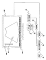
- FIG. 1 is a diagram showing a block configuration of an ultrasonic diagnostic apparatus according to an embodiment of the present invention.
- the probe 10 is brought into contact with the subject and transmits ultrasonic waves to the subject, and receives a reflected echo signal from the subject.
- the ultrasonic image measurement unit 20 performs signal processing such as phasing on the reflected echo signal, and includes a brightness (B) mode image, a motion (M) mode image, a Doppler (D) mode image, and an elasticity (E) mode image.
- An ultrasonic image is measured.
- the first display unit 100 displays the measured ultrasonic image.
- the input unit 50 inputs parameters for controlling the ultrasonic image measurement unit 20 and the first display unit 100.
- the control unit 60 controls the ultrasonic image measurement unit 20 and the first display unit 100 according to the parameters input to the input unit 50.
- the display control unit 80 inputs the first control parameter to the second display unit 70 by the operator and confirms the input of the first control parameter, and the next item of the confirmed first control parameter
- a menu for setting the second control parameter is generated in a part of the first display unit 100, the generated menu is displayed on the first display unit 100, and a switch associated with the menu is set. Display control is performed on the second display unit 70.
- the first control parameter is a measurement desired by the operator, such as various measurement conditions such as a B-mode image, an M-mode image, a D-mode image, and an E-mode image, and applications such as a body mark and a distance measurement.
- the type of analysis execution program is a condition that should be set next to the type of execution program for the desired measurement or analysis, for example, if it is a body mark, whether the site where the ultrasound probe is to be applied is the front or side of the abdomen To choose.
- control parameters are set in two stages such as the first and second control parameters.
- a third control parameter and a fourth control parameter are further provided as in three-dimensional measurement.
- it may be set in a plurality of stages as necessary.
- the first display unit 100 displays, for example, a B-mode image 101 obtained using a convex probe and a gray scale 102 indicating the luminance range of the displayed B-mode image.
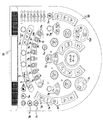
- the display area 103 is a function key display area for displaying the function keys of the touch panel of the present invention, and is referred to as a function key display area 103.
- the first embodiment is an example in which the function key array displayed on the function key display area 103 of the first display unit 100 and the function key array displayed on the second display unit 70 are displayed in a one-to-one correspondence.
- An example in which measurement is set for the first control parameter will be described with reference to FIGS.
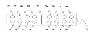
- FIG. 2 is a diagram for explaining an example of the key arrangement of the first embodiment of the ultrasonic diagnostic apparatus of FIG. 2A is a diagram showing the function key display area 103 of the first display unit 100
- FIG. 2B is a diagram showing that the second display unit (touch panel) 70 is disposed on the input unit 50
- FIG. 2C is the diagram of FIG. 2 is an enlarged view of a display 70.
- the function key display area 103 includes a measurement type switch 104 indicating distance measurement, a center line 105 indicating the center of the key arrangement, each of the keys 106a to 106h on the left side of the center line 105, and a center.
- the keys 107a to 107h on the right side from the line 105 are displayed.
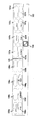
- FIG. 3 is a flowchart for explaining an example of the operation of the first embodiment.
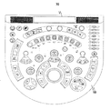
- the operator presses the measurement function execution key of the second display unit 70 (physical operation key linked to the touch panel). Specifically, when the operator presses the measurement key 104 (caliper, trace) on the operation panel when executing the measurement function, the measurement function is executed from the operation panel or touch panel, and then the touch panel display switches to the measurement content. In this step, a measurement button is displayed.
- the control unit 60 sets measurement for the button group ID.
- the control unit 60 acquires button display group data stored in a table on the storage unit 40 such as a memory using the button group ID as a key.
- the display control unit 80 switches and sets buttons on the second display unit 70 (touch panel).
- the display control unit 80 displays on the second display unit 70 measurement-related buttons that are the second condition for measurement setting. (Step 305).
- FIG. 4 is a diagram for explaining an example of a key arrangement of the second embodiment of the ultrasonic diagnostic apparatus of FIG.
- FIG. 4 is a diagram showing the function key display area 103 of the first display unit 100.
- the display control unit 80 performs display control in association with the body mark of the key 106a so that the key 72 a is obtained. Specifically, the key information of the body mark function of the key 106a is read by the control unit 60 to the storage unit 40, and the control unit 60 causes the display control unit 80 to analyze that the key information is the body mark function. 80 displays the analyzed key information on the key 72a. This execution is performed according to the program of the computer constituting the control unit 60 and the display control unit 80 as shown in the procedure of FIG.
- FIG. 5 is a flowchart for explaining an example of the operation of the second embodiment.
- Step 505 the display control unit 80 inputs the first control parameter to the second display unit 70 by the operator, and the first control parameter A menu for setting the second control parameter that is the next item of the confirmed first control parameter is generated in a part of the first display unit 100, and the generated menu Is displayed on the first display unit 100, and the menu and the switch are associated with each other and displayed on the second display unit 70.
- the display control target is a menu for selecting the first control parameter as a body mark and selecting the second control parameter as the type of the body mark.
- the enlarged display setting on the first display unit 100 is also reflected and displayed on the touch panel button of the second display unit 70.
- 16 buttons are displayed to make it easy for the operator to associate the 16 keys on the operation panel.
- the operator can perform the condition setting work more intuitively.
- the third embodiment is an example in which the function key array displayed on the function key display area 103 of the first display unit 100 and the function key array displayed on the second display unit 70 are displayed in a one-to-one correspondence.
- An example in which Doppler measurement is set as the first control parameter will be described with reference to FIGS.
- the display control unit 80 is arranged in conjunction with the arrangement of function keys displayed in the function key display area 103 of the first display unit 100 and the second so as to be interlocked with Doppler measurement. Display control of the arrangement of function keys displayed on the display unit 70 is performed. This execution is performed according to the program of the computer constituting the control unit 60 and the display control unit 80 as shown in the procedure of FIG.
- FIG. 7 is a flowchart for explaining an example of the operation of the third embodiment.
- the Doppler function display on the second display unit 70 is switched in the following steps.
- the control unit 60 sets the Doppler function to the button group ID.
- the control unit 60 acquires button display group data stored in a table on the storage unit 40 such as a memory using the button group ID as a key.
- the display control unit 80 switches and sets buttons on the second display unit 70 (touch panel).
- the display control unit 80 displays on the second display unit 70 measurement-related buttons that are the second condition for Doppler function setting.
- Step 705 the display control unit 80 inputs the first control parameter to the second display unit 70 by the operator, and the first control parameter A menu for setting the second control parameter that is the next item of the confirmed first control parameter is generated in a part of the first display unit 100, and the generated menu Is displayed on the first display unit 100, and the menu and the switch are associated with each other and displayed on the second display unit 70.
- the push type executes a certain function, such as an image left / right reverse button.
- the toggle type is a function that clearly indicates on / off of a switch, such as a moving image continuous playback button.
- the encoder type switches the value of a certain function of the device by operating the encoder of the touch panel, such as a B image gray map switching button.
- the control unit 60 causes the display control unit 80 to display buttons on the second display unit 70 (touch panel).
- the display control unit 80 has a button switch for displaying on the second display unit 70 according to the input condition of the first control parameter. A shape is set, and display control is performed on the second display unit 70 according to the shape of the set button switch.
- the unique effect of the fourth embodiment is that the operator can determine the operation target in accordance with the button shape of the menu, so that the condition setting operation can be performed more intuitively.
- the display unit has been described with the first display unit and the second display unit, the display unit may be divided into two display areas.
- the control unit and the display control unit are described separately, the function of the display control unit may be performed by the control unit.
Landscapes
- Life Sciences & Earth Sciences (AREA)
- Engineering & Computer Science (AREA)
- Health & Medical Sciences (AREA)
- Physics & Mathematics (AREA)
- Heart & Thoracic Surgery (AREA)
- Surgery (AREA)
- Nuclear Medicine, Radiotherapy & Molecular Imaging (AREA)
- Pathology (AREA)
- Radiology & Medical Imaging (AREA)
- Biomedical Technology (AREA)
- Veterinary Medicine (AREA)
- Medical Informatics (AREA)
- Molecular Biology (AREA)
- Biophysics (AREA)
- Animal Behavior & Ethology (AREA)
- General Health & Medical Sciences (AREA)
- Public Health (AREA)
- Human Computer Interaction (AREA)
- Computer Networks & Wireless Communication (AREA)
- General Physics & Mathematics (AREA)
- Radar, Positioning & Navigation (AREA)
- Remote Sensing (AREA)
- Ultra Sonic Daignosis Equipment (AREA)
Abstract
Description
第1の実施形態は、第1表示部100のファンクションキー表示領域103に表示されるファンクションキーの配列と第2表示部70に表示されるファンクションキーの配列が一対一対応で表示される例で、第1の制御パラメータに計測が設定されて例について図2、図3を用いて説明する。
図2Aは第1表示部100のファンクションキー表示領域103を示す図、図2Bは入力部50に上に第2表示部(タッチパネル)70を配置することを示す図、図2Cは図2Bの第2表示部70の拡大図である。
表示制御部80は、キー106 eの計測に連動してキー72eとなるように表示制御を行う。具体的には、キー106 eの計測機能のキー情報を制御部60が記憶部40に読み出し、制御部60がキー情報を計測機能であることを表示制御部80に解析させ、表示制御部80は解析したキー情報をキー72aに反映して表示させる。この実行は制御部60、表示制御部80を構成しているコンピュータのプログラムによって図3の手順のように行われる。
操作者は第2表示部70(タッチパネルに連動した物理操作キー)の計測機能実行キーを押す。具体的には、操作者は計測機能実行時に操作パネルの計測キー104(キャリパ、トレース)を押すと、操作パネルやタッチパネルから計測機能を実行した後、タッチパネル表示が計測用の内容に切り替わり、以下のステップで計測用のボタンが表示されることとなる。(ステップ301)
制御部60は、ボタングループIDに計測を設定する。(ステップ302)
制御部60は、ボタングループIDをキーにしてメモリなどの記憶部40上のテーブルに格納されたボタン表示グループのデータを取得する。(ステップ303)
表示制御部80は、第2表示部70(タッチパネル)上でボタンを切替設定する。(ステップ304)
表示制御部80は、第2表示部70に計測設定の第二条件となる計測関連ボタンを表示する。(ステップ305)。

第2の実施形態は、第1表示部100のファンクションキー表示領域103に表示されるファンクションキーの配列と第2表示部70に表示されるファンクションキーの配列が一対一対応で表示される例で、第1の制御パラメータにボディマークが設定されて例について図4、図5を用いて説明する。
図4は第1表示部100のファンクションキー表示領域103を示す図である。
制御部60は、ボタングループIDにボディマークを設定する。(ステップ502)
制御部60は、ボタングループIDをキーにしてメモリなどの記憶部40上のテーブルに格納されたボタン表示グループのデータを取得する。(ステップ503)
表示制御部80は、第2表示部70(タッチパネル)上でボタンを切替設定する。(ステップ504)
表示制御部80は、第2表示部70にボディマーク設定の第二条件となる計測関連ボタンを表示する。(ステップ505)
以上説明したように、第2の実施形態の超音波診断装置によれば、表示制御部80は、操作者によって第2表示部70に第1の制御パラメータを入力してその第1の制御パラメータの入力を確定させると共に、その確定された第1の制御パラメータの次項目となる第2の制御パラメータを設定するためのメニューを第1表示部100の一部に生成し、該生成されたメニューを前記第1表示部100に表示制御するとともに、前記メニューと前記スイッチとを対応付けて前記第2表示部70に表示制御する。
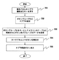
第3の実施形態は、第1表示部100のファンクションキー表示領域103に表示されるファンクションキーの配列と第2表示部70に表示されるファンクションキーの配列が一対一対応で表示される例で、第1の制御パラメータにドプラ計測が設定されて例について図6、図7を用いて説明する。
制御部60は、ボタングループIDにドプラ機能を設定する。(ステップ702)
制御部60は、ボタングループIDをキーにしてメモリなどの記憶部40上のテーブルに格納されたボタン表示グループのデータを取得する。(ステップ703)
表示制御部80は、第2表示部70(タッチパネル)上でボタンを切替設定する。(ステップ704)
表示制御部80は、第2表示部70にドプラ機能設定の第二条件となる計測関連ボタンを表示する。(ステップ705)
以上説明したように、第3の実施形態の超音波診断装置によれば、表示制御部80は、操作者によって第2表示部70に第1の制御パラメータを入力してその第1の制御パラメータの入力を確定させると共に、その確定された第1の制御パラメータの次項目となる第2の制御パラメータを設定するためのメニューを第1表示部100の一部に生成し、該生成されたメニューを前記第1表示部100に表示制御するとともに、前記メニューと前記スイッチとを対応付けて前記第2表示部70に表示制御する。
第4の実施形態は、第1表示部100のファンクションキー表示領域103に表示されるファンクションキーの配列と第2表示部70に表示されるファンクションキーの配列が一対一対応で表示される例で、図8、図9を用いて説明する。
操作者は、第2表示部70(タッチパネル)の表示される対象ボタンを設定する。(ステップ902)
制御部60は、対象ボタンのボタン型がエンコーダ型であるか否かを判定する。判定結果がエンコーダ型であればステップ904に進み、エンコーダ型でなければステップ905に進む。(ステップ903)
制御部60は、記憶部(メモリ)40上に記憶されたエンコーダ型のボタン形状データとそれに付随するデータを取得する。(ステップ904)
制御部60は、対象ボタンのボタン型がトグル型であるか否かを判定する。判定結果がトグル型であればステップ906に進み、エンコーダ型でなければステップ907に進む。(ステップ905)
制御部60は、記憶部(メモリ)40上に記憶されたトグル型のボタン形状データとそれに付随するデータを取得する。(ステップ906)
制御部60は、記憶部(メモリ)40上に記憶されたプッシュ型のボタン形状データとそれに付随するデータを取得する。(ステップ907)
制御部60は、全ての対象ボタンのデータを取得したか否かの判定を行う。判定の結果、全ての対象ボタンのデータを取得していればステップ910に進み、取得していなければステップ909に進む。(ステップ908)
制御部60は、対象ボタンを現在のものから、次のものへ切り替える。(ステップ909)
制御部60は、表示制御部80に第2表示部70(タッチパネル)上にボタンを表示させる。(ステップ910)
以上説明したように、第4の実施形態の超音波診断装置によれば、表示制御部80は、前記第1の制御パラメータの入力条件により、第2表示部70に表示するためのボタンスイッチの形状を設定し、その設定されたボタンスイッチの形状により第2表示部70に表示制御する。
Claims (6)
- 被検体の超音波画像を計測する超音波画像計測部と、
前記超音波画像を表示する表示部と、
前記超音波画像計測部と前記表示部を制御するためのパラメータを入力する入力部と、
前記パラメータにより前記超音波画像計測部と前記表示部を制御する制御部と、を備えた超音波診断装置であって、
前記制御部は、前記パラメータうちの第1の制御パラメータについて入力する第1スイッチ情報を生成し、前記第1スイッチ情報を前記表示部に表示させ、前記第1スイッチ情報から選択して前記第1の制御パラメータを入力し、前記第1の制御パラメータの次項目となる第2の制御パラメータの第2スイッチ情報を生成し、前記第2スイッチ情報を前記表示部に表示させることを特徴とする超音波診断装置。 - 前記表示部は、超音波画像を表示する第1表示部と、
前記第1スイッチ情報又は前記第2スイッチ情報を表示する第2表示部と、を備えたことを特徴とする請求項1に記載の超音波診断装置。 - 前記制御部は、前記第1スイッチ情報を画像中の所定点間の距離、面積、体積を含む計測メニューとすることを特徴とする請求項1に記載の超音波診断装置。
- 前記制御部は、前記第1スイッチ情報をボディマークの種類を選択するメニューとすることを特徴とする請求項1に記載の超音波診断装置。
- 前記制御部は、前記第1スイッチ情報をドプラモードの設定条件を選択するメニューとすることを特徴とする請求項1に記載の超音波診断装置。
- 前記制御部は、前記第1スイッチ情報により異なる形状のボタンスイッチを前記表示部に表示させることを特徴とする請求項1に記載の超音波診断装置。
Priority Applications (3)
| Application Number | Priority Date | Filing Date | Title |
|---|---|---|---|
| JP2010532939A JP5555171B2 (ja) | 2008-10-07 | 2009-10-07 | 超音波診断装置 |
| US13/122,497 US8693280B2 (en) | 2008-10-07 | 2009-10-07 | Ultrasonic diagnostic apparatus |
| CN2009801389620A CN102170831A (zh) | 2008-10-07 | 2009-10-07 | 超声波诊断装置 |
Applications Claiming Priority (2)
| Application Number | Priority Date | Filing Date | Title |
|---|---|---|---|
| JP2008-260372 | 2008-10-07 | ||
| JP2008260372 | 2008-10-07 |
Publications (1)
| Publication Number | Publication Date |
|---|---|
| WO2010041683A1 true WO2010041683A1 (ja) | 2010-04-15 |
Family
ID=42100632
Family Applications (1)
| Application Number | Title | Priority Date | Filing Date |
|---|---|---|---|
| PCT/JP2009/067487 Ceased WO2010041683A1 (ja) | 2008-10-07 | 2009-10-07 | 超音波診断装置 |
Country Status (4)
| Country | Link |
|---|---|
| US (1) | US8693280B2 (ja) |
| JP (1) | JP5555171B2 (ja) |
| CN (1) | CN102170831A (ja) |
| WO (1) | WO2010041683A1 (ja) |
Families Citing this family (6)
| Publication number | Priority date | Publication date | Assignee | Title |
|---|---|---|---|---|
| FR2928257B1 (fr) * | 2008-03-04 | 2011-01-14 | Super Sonic Imagine | Systeme electronique de visualisation a double ecran. |
| CN106462657B (zh) * | 2014-03-14 | 2020-04-07 | B-K医疗公司 | 超声成像系统的图形虚拟控件 |
| WO2016060475A1 (en) * | 2014-10-15 | 2016-04-21 | Samsung Electronics Co., Ltd. | Method of providing information using plurality of displays and ultrasound apparatus therefor |
| EP3784138A1 (en) | 2018-04-24 | 2021-03-03 | Supersonic Imagine | Ultrasound imaging system |
| JP2023170787A (ja) * | 2022-05-20 | 2023-12-01 | 富士フイルムヘルスケア株式会社 | 超音波診断装置および超音波情報処理装置 |
| KR20250076283A (ko) * | 2023-11-22 | 2025-05-29 | 삼성메디슨 주식회사 | 사용자 인터페이스를 제공하는 방법 및 그에 따른 초음파 영상 장치 |
Citations (3)
| Publication number | Priority date | Publication date | Assignee | Title |
|---|---|---|---|---|
| JP2005270317A (ja) * | 2004-03-24 | 2005-10-06 | Toshiba Corp | 超音波画像診断装置 |
| JP2007260188A (ja) * | 2006-03-29 | 2007-10-11 | Hitachi Medical Corp | 超音波診断装置 |
| JP2008026468A (ja) * | 2006-07-19 | 2008-02-07 | Sony Corp | 画像表示装置 |
Family Cites Families (7)
| Publication number | Priority date | Publication date | Assignee | Title |
|---|---|---|---|---|
| US6468212B1 (en) * | 1997-04-19 | 2002-10-22 | Adalberto Vara | User control interface for an ultrasound processor |
| US6674879B1 (en) * | 1998-03-30 | 2004-01-06 | Echovision, Inc. | Echocardiography workstation |
| US6238341B1 (en) * | 1998-12-28 | 2001-05-29 | General Electric Company | Ultrasound probe having integrated user-operable function switch |
| US20020173721A1 (en) * | 1999-08-20 | 2002-11-21 | Novasonics, Inc. | User interface for handheld imaging devices |
| JP2002248099A (ja) | 2001-02-26 | 2002-09-03 | Aloka Co Ltd | 超音波診断装置 |
| US9049979B2 (en) * | 2005-09-30 | 2015-06-09 | Koninklijke Philips N.V. | User interface system and method for creating and managing ultrasound measurement-based calculations in ultrasound imaging system |
| JP5231726B2 (ja) * | 2006-07-27 | 2013-07-10 | 株式会社ニデック | 眼科用超音波診断装置 |
-
2009
- 2009-10-07 CN CN2009801389620A patent/CN102170831A/zh active Pending
- 2009-10-07 WO PCT/JP2009/067487 patent/WO2010041683A1/ja not_active Ceased
- 2009-10-07 JP JP2010532939A patent/JP5555171B2/ja active Active
- 2009-10-07 US US13/122,497 patent/US8693280B2/en active Active
Patent Citations (3)
| Publication number | Priority date | Publication date | Assignee | Title |
|---|---|---|---|---|
| JP2005270317A (ja) * | 2004-03-24 | 2005-10-06 | Toshiba Corp | 超音波画像診断装置 |
| JP2007260188A (ja) * | 2006-03-29 | 2007-10-11 | Hitachi Medical Corp | 超音波診断装置 |
| JP2008026468A (ja) * | 2006-07-19 | 2008-02-07 | Sony Corp | 画像表示装置 |
Also Published As
| Publication number | Publication date |
|---|---|
| JP5555171B2 (ja) | 2014-07-23 |
| CN102170831A (zh) | 2011-08-31 |
| JPWO2010041683A1 (ja) | 2012-03-08 |
| US8693280B2 (en) | 2014-04-08 |
| US20110182137A1 (en) | 2011-07-28 |
Similar Documents
| Publication | Publication Date | Title |
|---|---|---|
| JP5555171B2 (ja) | 超音波診断装置 | |
| CN113768545B (zh) | 一种超声瞬时弹性测量设备及方法 | |
| KR101313218B1 (ko) | 휴대형 초음파 시스템 | |
| JP5737823B2 (ja) | 超音波診断装置 | |
| KR20100110893A (ko) | 초음파 진단 장치 | |
| US8701035B2 (en) | Index image control apparatus | |
| KR101167248B1 (ko) | 터치 인터랙션을 사용하는 초음파 진단 장치 | |
| JP2012019824A (ja) | 超音波診断装置 | |
| JP6063454B2 (ja) | 超音波診断装置及び軌跡表示方法 | |
| CN101721225A (zh) | 超声波诊断装置 | |
| US9289189B2 (en) | Ultrasound diagnostic apparatus | |
| JP5523694B2 (ja) | 超音波診断装置 | |
| CN102626326A (zh) | 触摸屏超声诊断仪的测量点定位方法及系统 | |
| JP5239401B2 (ja) | 超音波診断装置 | |
| US6743176B2 (en) | Ultrasonic image display apparatus and ultrasonic image display method | |
| CN113100832B (zh) | 超声波诊断装置和程序存储介质 | |
| JP5270159B2 (ja) | 画像診断装置 | |
| JPWO2022244552A5 (ja) | ||
| WO2017104263A1 (ja) | 超音波観測装置、処理装置、超音波観測装置の作動方法および超音波観測装置の作動プログラム | |
| JP2012095691A (ja) | 超音波画像処理装置およびプログラム | |
| JP5329857B2 (ja) | 超音波診断装置 | |
| JP6162968B2 (ja) | 超音波診断装置 | |
| JPH0724309U (ja) | 超音波診断装置 | |
| JP2019005430A (ja) | 超音波装置、データ表示装置及びプログラム | |
| KR20130138157A (ko) | 초음파 진단 장치 및 그 제어방법 |
Legal Events
| Date | Code | Title | Description |
|---|---|---|---|
| WWE | Wipo information: entry into national phase |
Ref document number: 200980138962.0 Country of ref document: CN |
|
| 121 | Ep: the epo has been informed by wipo that ep was designated in this application |
Ref document number: 09819217 Country of ref document: EP Kind code of ref document: A1 |
|
| WWE | Wipo information: entry into national phase |
Ref document number: 2010532939 Country of ref document: JP |
|
| WWE | Wipo information: entry into national phase |
Ref document number: 13122497 Country of ref document: US |
|
| NENP | Non-entry into the national phase |
Ref country code: DE |
|
| 122 | Ep: pct application non-entry in european phase |
Ref document number: 09819217 Country of ref document: EP Kind code of ref document: A1 |