WO2010035800A1 - 水浄化システム及び浄化対象水中の溶存酸素濃度の増加方法 - Google Patents
水浄化システム及び浄化対象水中の溶存酸素濃度の増加方法 Download PDFInfo
- Publication number
- WO2010035800A1 WO2010035800A1 PCT/JP2009/066681 JP2009066681W WO2010035800A1 WO 2010035800 A1 WO2010035800 A1 WO 2010035800A1 JP 2009066681 W JP2009066681 W JP 2009066681W WO 2010035800 A1 WO2010035800 A1 WO 2010035800A1
- Authority
- WO
- WIPO (PCT)
- Prior art keywords
- water
- fiber
- dissolved oxygen
- purification
- oxygen concentration
- Prior art date
- Legal status (The legal status is an assumption and is not a legal conclusion. Google has not performed a legal analysis and makes no representation as to the accuracy of the status listed.)
- Ceased
Links
Images

Classifications
-
- C—CHEMISTRY; METALLURGY
- C02—TREATMENT OF WATER, WASTE WATER, SEWAGE, OR SLUDGE
- C02F—TREATMENT OF WATER, WASTE WATER, SEWAGE, OR SLUDGE
- C02F3/00—Biological treatment of water, waste water, or sewage
- C02F3/02—Aerobic processes
- C02F3/10—Packings; Fillings; Grids
- C02F3/101—Arranged-type packing, e.g. stacks, arrays
-
- C—CHEMISTRY; METALLURGY
- C02—TREATMENT OF WATER, WASTE WATER, SEWAGE, OR SLUDGE
- C02F—TREATMENT OF WATER, WASTE WATER, SEWAGE, OR SLUDGE
- C02F3/00—Biological treatment of water, waste water, or sewage
- C02F3/02—Aerobic processes
- C02F3/06—Aerobic processes using submerged filters
-
- C—CHEMISTRY; METALLURGY
- C02—TREATMENT OF WATER, WASTE WATER, SEWAGE, OR SLUDGE
- C02F—TREATMENT OF WATER, WASTE WATER, SEWAGE, OR SLUDGE
- C02F1/00—Treatment of water, waste water, or sewage
- C02F1/28—Treatment of water, waste water, or sewage by sorption
- C02F1/283—Treatment of water, waste water, or sewage by sorption using coal, charred products, or inorganic mixtures containing them
-
- C—CHEMISTRY; METALLURGY
- C02—TREATMENT OF WATER, WASTE WATER, SEWAGE, OR SLUDGE
- C02F—TREATMENT OF WATER, WASTE WATER, SEWAGE, OR SLUDGE
- C02F2103/00—Nature of the water, waste water, sewage or sludge to be treated
- C02F2103/007—Contaminated open waterways, rivers, lakes or ponds
-
- Y—GENERAL TAGGING OF NEW TECHNOLOGICAL DEVELOPMENTS; GENERAL TAGGING OF CROSS-SECTIONAL TECHNOLOGIES SPANNING OVER SEVERAL SECTIONS OF THE IPC; TECHNICAL SUBJECTS COVERED BY FORMER USPC CROSS-REFERENCE ART COLLECTIONS [XRACs] AND DIGESTS
- Y02—TECHNOLOGIES OR APPLICATIONS FOR MITIGATION OR ADAPTATION AGAINST CLIMATE CHANGE
- Y02W—CLIMATE CHANGE MITIGATION TECHNOLOGIES RELATED TO WASTEWATER TREATMENT OR WASTE MANAGEMENT
- Y02W10/00—Technologies for wastewater treatment
- Y02W10/10—Biological treatment of water, waste water, or sewage
-
- Y—GENERAL TAGGING OF NEW TECHNOLOGICAL DEVELOPMENTS; GENERAL TAGGING OF CROSS-SECTIONAL TECHNOLOGIES SPANNING OVER SEVERAL SECTIONS OF THE IPC; TECHNICAL SUBJECTS COVERED BY FORMER USPC CROSS-REFERENCE ART COLLECTIONS [XRACs] AND DIGESTS
- Y02—TECHNOLOGIES OR APPLICATIONS FOR MITIGATION OR ADAPTATION AGAINST CLIMATE CHANGE
- Y02W—CLIMATE CHANGE MITIGATION TECHNOLOGIES RELATED TO WASTEWATER TREATMENT OR WASTE MANAGEMENT
- Y02W10/00—Technologies for wastewater treatment
- Y02W10/30—Wastewater or sewage treatment systems using renewable energies
- Y02W10/37—Wastewater or sewage treatment systems using renewable energies using solar energy
Definitions
- This invention removes pollutants using living organisms from environmental water such as fresh water, brackish water, sea water, etc. existing in rivers, waterways, canals, ponds, lakes, bays, coves, oceans, etc., and industrial wastewater and sewage.
- the present invention relates to a water purification system and a method for increasing dissolved oxygen concentration in water to be purified.
- the progress of water pollution is related to the fact that water is artificially polluted and polluted more than the natural resilience.
- bottom mud containing malodorous substances accumulates on the bottom of rivers, lakes, and other water.
- the bottom mud is generally called sludge.
- dissolved oxygen in water is indispensable for aerobic microorganisms to decompose pollutants and purify water. This is because when there is no dissolved oxygen in the water, the state becomes anaerobic, and the degradation rate of the pollutant by the aerobic microorganisms, that is, the purification rate of water is remarkably reduced.
- cocoon is generally well known.
- useful organisms that live in the bottom mud such as microorganisms and bacteria, are drawn out and discarded.
- plants such as aquatic plants are forcibly removed, the ecosystem will be destroyed.
- Japanese Patent Laid-Open No. 2001-47095 discloses a method of dephosphorizing, denitrifying and deammonizing sludge using iron slag discharged from an ironworks without using soot.
- this method is intended to decompose and remove nitrogen and phosphorus in sludge and not to decompose and remove carbon components, which are the main components of sludge. Low. For this reason, it was necessary to artificially replenish denitrifying bacteria using a mesh bag or the like to decompose the bottom mud.
- the object of the present invention is to artificially trap the bottom mud, or artificially supplement the water bottom with microorganisms, bacteria, etc. to decompose the bottom mud.
- the object is to provide a water purification system that decomposes and removes bottom mud using biological resources existing in nature as it is and a method for increasing the dissolved oxygen concentration in the water to be purified.
- Another object of the present invention is to actively propagate organisms existing in nature in the purification target water, purify the purification target water by decomposing and removing pollutants or pollutants from the purification target water,
- the present invention is to provide a water purification system that positively utilizes water for decomposing and removing bottom mud in the water to be purified and a method for increasing the dissolved oxygen concentration in the water to be purified.
- the present inventor has found that the carbon material is suitable for the propagation and fixation of aerobic bacteria, and by disposing the carbon fiber in the water and the carbon material in the bottom mud, the bottom mud is effectively decomposed, and the environment I came up with water purification.
- aerobic with the ability to decompose the bottom mud by placing the fiber water purification material such as carbon fiber water purification material in the water and burying carbon material such as charcoal and carbon fiber in the bottom mud
- bacteria can be propagated and the bottom mud can be decomposed.
- the water purification system of the present invention that can purify polluted water or contaminated water.
- the aerobic bacteria existing in the water adhere to and propagate on a specific fiber water purification material such as a carbon fiber water purification material immersed in water.
- a specific fiber water purification material such as a carbon fiber water purification material immersed in water.
- a part of the aerobic bacteria grown through the fiber water purification material moves to the bottom of the water, and the aerobic bacteria grow in the carbon material placed on the bottom of the water, so that the aerobic bacteria decompose the bottom mud. It was inferred that the bottom mud would be decomposed by the
- the present inventor generates oxygen gas from plants when aerobic bacteria grow on the bottom of the water and, as a result, phytoplankton and plants grow. It was speculated that the dissolved oxygen concentration in the water increased and the decomposition of bottom mud by aerobic bacteria was further promoted. Then, when this inventor performed various experiments in order to confirm these assumptions, according to the water purification system of this invention, it was reconfirmed that bottom mud decomposes
- the present inventor measured the dissolved oxygen concentration in the water when conducting the experiment on the water purification system capable of decomposing the bottom mud, and found the location where the water purification system was installed and the water purification system. It was found that there was a significant difference in dissolved oxygen concentration in the water from where it was not. Moreover, surprisingly, when there is a difference in dissolved oxygen concentration, only two weeks have passed since the installation of the water purification system, so aquatic plants such as aquatic plants that supply oxygen have hardly propagated. Regardless, the concentration of dissolved oxygen increased significantly at the location of the water purification system. This is because by installing the above water purification system, the dissolved oxygen concentration in the water increases for some reason in connection with the growth of aerobic bacteria from the water to the fiber water purification material and carbon material. It was guessed that it was due to this.
- the present inventor has come up with the method for increasing the dissolved oxygen concentration in the purification target water of the present invention.
- the present invention is characterized by disposing a fiber water purification material in water and embedding a carbon material in the bottom mud, and reducing the dissolved oxygen concentration in the water without destroying the ecosystem.
- the bottom mud is decomposed and removed.
- a fiber water purification material immersed in the purification target water, and the bottom surface of the purification target water and the wall of the purification target water area A carbon material covering at least one part or all of the carbonaceous material, and adhering pollutants and / or organisms that decompose the pollutants contained in the water to be purified to the fiber water purification material,
- a “water purification system” in which the fiber water purification material is disposed so as to be movable to a raw material, and the dissolved oxygen concentration in the purification target water is increased.
- a fiber water purification material is immersed in the purification target water, Cover part or all of at least one of the walls of the water area to be purified with a carbon material, and attach and propagate the pollutants and / or organisms that decompose the pollutants contained in the water to be purified to the water purification material made of fiber.
- a method of increasing the dissolved oxygen concentration in the purification target water wherein the grown organism is moved from the fiber water purification material to the carbon material and the dissolved oxygen concentration in the purification target water is increased.
- the fiber water purification material when the fiber water purification material is immersed in the water to be purified as a structure that rises like aquatic plants or is suspended from a floating body on the water surface, aerobic bacteria adhere to the fiber water purification material and grow. At the same time, the aerobic bacteria grown through the fiber water purification material are transferred to the carbon material covering at least one or all of the upper surface of the bottom of the water to be purified and the wall of the water to be purified, and are propagated thereby.
- the bottom mud can be decomposed and removed.
- a carbon material, carbon fiber, activated carbon fiber, oxidized fiber in which carbon material to be installed on at least one part or all of the bottom surface of the water bottom and the wall of the water area to be purified is made of charcoal pieces, charcoal grains, or charcoal powder solidified with a binder.
- at least one material selected from flame-resistant fibers or a combination of two or more of the above materials an environment in which organisms such as aerobic bacteria can easily grow can be constructed.
- the fiber water purification material may be at least one fiber selected from carbon fiber, activated carbon fiber, oxidized fiber, flame-resistant fiber, para-aramid fiber, nylon fiber, vinylidene chloride fiber, and polyvinyl fiber, or 2 of the fibers.
- a combination of more than two species is preferable because organisms such as aerobic bacteria are likely to adhere to the fiber water purification material.
- a fiber obtained by heat-treating acrylic fiber at 200 to 300 ° C. as the oxidized fiber because organisms such as aerobic bacteria are more likely to adhere.
- the purification target water targeted by the present invention is (1) environmental water existing in dredging rivers, waterways, canals, ponds, lakes, bays, bays, oceans, etc., and (2) industrial wastewater discharged from dredging factories, etc. And / or (3) ⁇ wastewater containing excreta such as humans and livestock.
- the dissolved oxygen concentration in the water is increased.
- the concentration of dissolved oxygen in the water is high as a result of placing the fiber water purification material and carbon material in the water, which causes aerobic bacteria and other organisms in the water to propagate and promote water purification. To do.
- it increases the transparency of water, and sunlight reaches into the water, so that the plant breeds and generates oxygen gas by carbon dioxide assimilation, leading to a secondary increase in dissolved oxygen concentration, There is an especially remarkable effect that water purification is further promoted.
- an environment in which a part of organisms such as aerobic bacteria that have propagated in water are actively transferred to the carbon material installed on the water bottom or wall through the fiber water purification material. For this reason, the bottom mud is decomposed and removed by organisms such as aerobic bacteria that are normally present in nature.
- An important matter in a system and / or method for decomposing bottom mud, a system and / or method for purifying water quality, a system and / or method for growing seafood in water, etc. is the concentration of dissolved oxygen in water.
- the basis of water purification using the water purification system of the present invention is decomposition of bottom mud by aerobic bacteria. This is because the decomposition rate of the bottom mud is higher when it is carried out with aerobic bacteria.
- the degradation of the pollutant or the pollutant can be performed using either anaerobic bacteria or aerobic bacteria. If the degradation is performed by aerobic bacteria, the degradation products are carbon dioxide and water. In the case of decomposition by a sexual bacterium, the decomposition product is methane or the like.
- oxygen gas generated as a result of the growth of aerobic bacteria at the bottom of the water and the propagation of phytoplankton or plants is generated as a single molecule. It is smaller than the nano size, and is more preferable for use in the metabolic action of microorganisms.
- the present invention is also applicable to industrial wastewater, sewage and the like.
- the dissolved oxygen concentration in the water increases, so the decomposition of pollutants is promoted and water purification proceeds.
- the dissolved oxygen concentration in the water is increased, aerobic bacteria living in the water are collected and propagated in the water purification material made of fiber, and the proliferated aerobic bacteria are It can be moved into the carbon material installed in the bottom or bottom mud. Aerobic bacteria that migrated into the carbon material decomposed the bottom mud and mineralized the heavy oily bottom mud. These phenomena were verified by experiments.
- the fiber water purification material made of carbon fiber or the like disposed in the purification target water is preferably made of carbon fiber that rises like aquatic plants by a floating body or the like.
- the fiber water purification material made from these carbon fibers may be a centipede type, tuft type, etc., with the ends open and separated, or a molded body having a planar shape.
- the shape may be a sheet shape, a belt shape, a belt shape, a string shape, a cylinder shape, a pipe shape, a rod shape, a strip shape, a spiral shape, a spiral shape, a lattice shape, a perforated shape, or a net shape.
- the form of the fiber water purification material soaked in water is preferably not only raised in water but also suspended from a floating body on the water surface to a carbon material in the bottom mud.
- a floating body an object made of wood, bamboo, rubber, plastic, or the like, or a squid, a pontoon, a pier, a float, a buoy or the like connecting them can be used.
- a fiber water purification material is fixed to these floating bodies and suspended from there to the bottom mud.
- the fiber water purification material to be suspended can be the same as that used in the case of starting up from the water described above, and has a centipede shape, tuft shape, etc., and the end is open, or has a planar shape.
- a molded body or a woven fabric can also be used.
- the shape may be a sheet shape, a belt shape, a belt shape, a string shape, a cylinder shape, a pipe shape, a rod shape, a strip shape, a spiral shape, a spiral shape, a lattice shape, a perforated shape, or a net shape.
- a water purification material made of fiber a net made of carbon fiber, or a net made of carbon fiber such as charcoal or carbon fiber in a net made of chemical fiber or natural fiber, or charcoal packed You may use what attached carbon fiber to the outer peripheral part of the net so that it may shake in water.
- the carbon material covering at least part of the upper surface of the water bottom (bottom mud) or part or all of the wall of the water area to be purified may be charcoal fragments, charcoal grains, or charcoal powder.
- a molded product obtained by hardening charcoal powder with a binder such as hardened cement, gypsum, glass, plastic, starch, or the like may be used.
- it may be a centipede type or tuft type made of carbon fiber, which has an open end, or a woven shape having a planar shape.
- the shape of the carbon material can be a belt shape, a sheet shape, a belt shape, a string shape, a cylindrical shape, a pipe shape, a rod shape, a strip shape, a spiral shape, a spiral shape, a lattice shape, a perforated shape, a net shape, or the like.
- Such a carbon material embedded in the bottom mud because the effect of decomposing the bottom mud is further promoted.
- Examples of such a carbon material include carbon fiber and charcoal. Besides, bamboo or other biomass carbonized can be used. Coke produced from coal can also be used as a carbon material.
- the carbon material that covers the upper surface of the bottom mud or is embedded in the bottom mud may be an unprocessed thread-like carbon fiber itself or a long-fiber carbon fiber. Furthermore, the thing in which the carbon fiber of the short fiber was intertwined may be used. Even short carbon fibers are dispersed in the bottom mud, so that the decomposition of the bottom mud by aerobic bacteria is promoted.
- Carbonizing biomass with fiber forms such as silkworm, cotton, hemp, wool, silk, etc. has a problem in strength, but it becomes a carbon material, and by placing it in the bottom mud, it functions as a carbon material of the present invention. Demonstrate. Therefore, what carbonized the fiber product etc. which became unnecessary can be used as a carbon material arrange
- the fiber water purification material disposed in the water is in contact with or close to the carbon material covering at least a part of the upper surface of the water bottom (bottom mud) or a part or all of the wall part of the water area to be purified. . If it does in this way, aerobic bacteria adhering to the underwater textile water purification material will move to the carbon material in bottom mud easily, and bottom mud can be decomposed there.
- the proximity means, for example, that the distance is such that the fiber water purification material and the carbon material are in contact or not in contact with the flow of water.
- Examples of pollution sources in water include nitrogen and phosphorus. Microorganisms adhering to carbon fibers actively decompose nitrogen in water. However, since phosphorus does not change into a gaseous substance, removal from water is difficult.
- nitrogen and phosphorus are essential components for plants. Plants actively absorb nitrogen and phosphorus from roots as nutrient sources. Therefore, a water purification method is conceivable in which plants are arranged on the water, plant roots and carbon fibers are arranged in the water, and carbon materials are arranged in the bottom mud (water bottom). Specifically, it is possible to arrange a plant in the upper part of a floating body and arrange
- the carbon fiber to be attached to the lower part of the floating body the carbon fiber rising from the bottom as described above, or the carbon fiber suspended from the floating body, specifically, centipede type, tuft type, etc.
- Loose, flat, molded, sheet, belt, strip, string, tube, pipe, rod, strip, spiral, spiral, grid, perforated Or a net-like material can be used. By doing so, the roots of the grown plant and the carbon fiber are intertwined, so that the plant roots actively absorb phosphorus and nitrogen, thereby promoting the growth of the plant.
- plants absorb nitrogen and phosphorus in water efficiently, they die out in the winter, so that it becomes a problem that accumulated nitrogen and phosphorus are redissolved in water.
- One way to solve this problem is to cut the plants before they die and remove them outside the water environment. Therefore, it is desirable that the plant attached to the floating body is easy to cut. Specific examples include tall, shabu, reed, and kaya.
- the carbon fibers used in the present invention may be PAN-based or pitch-based. In view of price and strength, PAN-based long fibers are desirable as the carbon fibers disposed in water. On the other hand, the carbon fiber disposed in the bottom mud does not particularly require strength, and may be a pitch-based general-purpose fiber. When placed in the bottom mud, the length of the fiber is not particularly problematic.
- the PAN-based carbon fiber may have a different number of filaments, but the present invention is not particularly problematic in practice.
- oxidized fiber In the process of producing the PAN-based carbon fiber, when the acrylic fiber of the raw yarn is heat-treated at about 200 ° C. or more and 300 ° C. or less, oxidized fiber (for example, disclosed in Japanese Patent No. 2184095) or flame-resistant fiber (manufactured by Toho Tenax) , Pyromex TM, etc.). These fibers can also be used for water purification, and these oxidized fibers or flame-resistant fibers may be used in place of the carbon fibers disposed in the water.
- oxidized fiber for example, disclosed in Japanese Patent No. 2184095
- flame-resistant fiber manufactured by Toho Tenax
- Pyromex TM Pyromex
- the purification effect can be achieved by using oxidized fibers or flame-resistant fibers instead of carbon fibers arranged in the bottom mud or in place of part of the carbon fibers.
- the water purification effect is lower than in the case of carbon fiber.
- Carbon fiber surface sizing agent The surface of the carbon fiber is coated with a sizing agent so as to be well bonded to the base material when used as a composite material.
- a sizing agent when used for a composite material having a resin as a base material, an epoxy-based sizing agent is used to increase the bonding strength at the interface between the two.
- an epoxy-based sizing agent is used to increase the bonding strength at the interface between the two.
- One of the effects of the present invention is that the growth of aquatic plants is promoted.
- the transparency of water is improved.
- the degree of water transparency increases, so that sunlight reaches the vicinity of the bottom of the water to be purified, the photosynthetic action becomes active, and the plant grows.
- oxygen gas is generated, the amount of dissolved oxygen in water is further increased, the action of aerobic bacteria in water is activated, and the decomposition of pollutants is further promoted.
- Plant growth is preferable for water purification, and in the present invention, the growth of the plant is promoted by the action of the carbon material disposed in the bottom mud.
- Another effect of the present invention is that fish can grow and the water purification system functions as an algae basin.
- the number of fish increases. This is because the carbon fiber in the water becomes a spawning ground, a hiding place, a breeding ground, a feeding ground, etc. for fish.
- carbon fiber gathers a lot of plankton, and fish that prey on it gather.
- shellfish such as shellfish, shrimp, and crabs increased by placing carbon material on the top and bottom of the bottom mud.
- loaches and eels growing in the mud increased. These organisms prey on nutrients in the bottom mud and live. Such a phenomenon is also caused by an increase in dissolved oxygen concentration in water.
- the carbon material arranged in the bottom mud may be placed on the surface of the bottom mud, placed in the bottom mud, or placed only inside the bottom mud. Basically, it is preferable that the carbon fiber disposed in the water and the carbon material in the bottom mud are in contact with each other.
- the present inventor has discovered that the dissolved oxygen concentration in the water has increased by constructing the arrangement of the fiber water purification material and the carbon material in the environmental water in order to increase the dissolved oxygen concentration in the environmental water.
- the carbon concentration in the water and the carbon material on the top of the bottom mud significantly increased the dissolved oxygen concentration in the bottom.
- the present inventor has noticed that the dissolved oxygen concentration is higher at the place where the carbon fiber is suspended in the water and the carbon material is disposed at the bottom compared to the place where the carbon material is not installed.
- the dissolved oxygen concentration at the bottom of the water where the carbon fiber is placed is even lower than in the vicinity of the water surface. This is because dissolved oxygen is consumed by microorganisms adhering to the carbon fiber or bottom mud deposited on the bottom of the water. However, the dissolved oxygen concentration is higher in the place where the carbon material and the carbon fiber are arranged than in the place where the carbon material and the carbon fiber are not arranged.
- the property of the bottom mud changed.
- organic components were present in the bottom mud, which generated malodor and was viscous.
- fine particles in the bottom mud flowed out due to the decomposition of organic matter, and the pollution of the environmental water disappeared in a short time, causing an early improvement in transparency.
- the number of small fish has increased.
- shellfish were attached to the suspended carbon fiber.
- FIG. 1 is a plan view showing an embodiment of the water purification system of the present invention
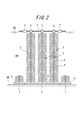
- FIG. 2 is a side view showing a part of the water purification system of the embodiment, as viewed from the direction of arrow A in FIG. is there.
- an experimental water tank 1 (12 m ⁇ 12 m) that is partitioned in a square shape by a wall portion made of a rubber sheet in a water area of a irrigation channel in which accumulated water slightly flows.
- the bottom of the experimental water tank 1 is a riverbed on which the bottom mud BM has accumulated, and water is soaked and exuded without any rubber sheet or the like. There is an inlet for the environmental water EW to the experimental water tank 1, but there is no outlet. The environmental water EW in the experimental water tank 1 oozes out little by little from the periphery of the rubber sheet, although the location is not clear.
- the water depth of the experimental water tank 1 is 1.5 m on average. In the lower part of the experimental water tank 1, about 20 cm of bottom mud BM was deposited, and generation of methane gas was observed before the water purification system was installed.
- a carbon fiber water purification material 2 as a fiber water purification material was suspended from a rope 3 stretched on the water surface WS through a small float 4. Three ropes 3 are stretched per one carbon material 6 (woven carbon fiber) described later. Furthermore, the large float 5 was arrange
- the carbon fiber water purification material 2 used was a centipede shape and a length of 60 cm made by Sobun Textile Joint Stock Company.
- the shape of the carbon fiber 9 (PAN-based, 12K) in the form of strands between the two polyester sheets (width 4 cm) in the central portion 8 is 1 cm apart in the longitudinal direction of the sheet, and the length of each side is 20 cm.
- the carbon fiber weight used for one carbon fiber water purification material 2 was 20 g. Since the water depth of the experimental water tank 1 was 1.5 m, 2.5 carbon fiber water purification materials 2 were connected by a binding band and used as a length of 1.5 m that matched the water depth.
- the carbon material 6 installed on the upper surface of the bottom mud BM of the experimental water tank 1, woven carbon fiber was used.
- This carbon material 6 was a plain weave made by Fukuoka Machine Co., Ltd., and had a length and width of 1 m ⁇ 1 m. In order to set this in the water, it was fixed to a steel mesh 7 (vertical and horizontal 1 m ⁇ 1 m) as a weight using a binding band as shown in FIG. Further, 2.5 carbon centipede-shaped carbon fiber water purification materials 2 connected to each carbon material 6 were arranged in a series of 3 ⁇ 3 in length and width, and a total of 9 were fixed.
- Purification material 2 and carbon material 6 were installed on August 11, 2008.
- the dissolved oxygen concentration at that time was about 10 mg / l near the water surface and about 1 mg / l or less at the bottom of the water.
- the dissolved oxygen concentration was measured using a DO meter (manufactured by Iijima Electronics Co., Ltd., 1D-100). Measurements were made at different locations in the experimental water tank 1, but the values were similar.
- the dissolved oxygen concentration was measured again 14 days after the purification material 2 and the carbon material 6 were installed. In the vicinity of the place where the influent water (environmental water EW) was introduced, it was 10 mg / l near the water surface, 5 mg / l 100 cm below the water surface, and 1 mg / l or less at the bottom. This was the same value as before installation. However, the dissolved oxygen concentration changed in the water area where the purifying material 2 and the carbon material 6 were arranged. It was 10 mg / l near the water surface, which was the same value as the inflow region. However, the value at the bottom of the water was 3 to 4 mg / l, which was different from that before installation. Although the measurement position was changed in the place where the purification material 2 and the carbon material 6 were arranged, the same numerical values were obtained.
- the inflow water flows out from the experimental water tank 1 after passing through the purification material 2 and the carbon material 6. Then, when dissolved oxygen concentration was measured in the water area downstream from the installation area of the purification material 2 and the carbon material 6, it was the same numerical value as the location in which the purification material 2 and the carbon material 6 were installed. From these facts, it was found that the dissolved oxygen concentration in the water is improved by suspending the carbon fiber water purification material 2 in water and disposing the woven carbon material 6 at the bottom.
- the transparency of the water sampled in each basin was measured. Although it was 10 cm in the inflow area, it was 20 cm in the water area where the purifying material 2 and the carbon material 6 were arranged. In the downstream area from here, it was 15 cm between the two.
- the surface water at the center of the water area where the purification material 2 and the carbon material 6 were installed was collected.
- the water collection was performed without attaching the water collection container to the end of a long stick and stirring the surrounding water. Observation of the collected water revealed that five zooplankton, presumably daphnia, were swimming well.
- the surface water of the place where the purifying material 2 and the carbon material 6 are not installed was collected and observed by the same method. In this case, however, the presence of zooplankton was not observed.
- the reason why such a phenomenon occurs is that the zooplankton can grow in the water area where the purification material 2 and the carbon material 6 are installed, and thus the dissolved oxygen concentration is low in the water area where the water is not installed. However, it is thought that zooplankton cannot grow because it is very few.
- the concentration of dissolved oxygen was increased by placing the carbon material in the environmental water.
- the reasons are listed as follows. That is, the adhesive bacteria adhere to the carbon fibers launched in water, and the suspension of the suspended solids adheres to the adhesive bacteria, thereby improving the transparency of water. As a result, phytoplankton grew to near the bottom of the water, and oxygen gas was generated in the water. As a result, the dissolved oxygen concentration increased, aerobic bacteria grew, and the bottom mud was predated and decomposed by them, so that the bottom mud was deodorized and methane was not generated. Furthermore, the amount of oxygen gas generated was increased by improving the transparency and breeding underwater plants.
- adhesive bacteria are bacteria which secrete an adhesive substance, for example, Bacillus natto.
- Example 2 An experiment was conducted in a marsh (area of about 30,000 m 2 ) in the Kanto region, where sludge accumulates at the bottom, and in the summer, a blue sea lion occurs. Specifically, first, a squid (2m ⁇ 2m) made by combining bamboo materials as a floating body is manufactured, and a fiber water purification material formed by connecting three centipede-shaped carbon fibers in the length direction is spaced by 30cm. 49 (7 rows x 7 rows) were attached.
- the squid with the water purification material made of fiber was floated on the water surface at a depth of about 2 m in a part of the swamp, and the water purification material made of fiber was immersed in water and suspended from the squid. Furthermore, a fiber water purification material suspended from the squid by installing a woven carbon fiber (1m x 1m) as a carbon material attached to the iron net below the squid and above the bottom mud. The lower part of the fiber was brought into contact with the woven carbon fiber.
- the dissolved oxygen concentration of water in the lower part of the center of the squid was measured with a DO meter (manufactured by Iijima Electronics Co., Ltd., 1D-100).
- the dissolved oxygen concentration near the water surface was 18.0 mg / l
- the dissolved oxygen concentration 50 cm below the water surface was 17.5 mg / l.
- the dissolved oxygen concentration 1 m below the water surface is 12.0 mg / l
- the dissolved oxygen concentration 1.5 m below the water surface is 8.0 mg / l
- the dissolved oxygen concentration was measured in the same manner even at a location 10 m away from the squid, it was 19.1 mg / l near the water surface, 16.6 mg / l at 50 cm below the water surface, and 12 at 1 m below the water surface. 0.0 mg / l, and 1.6 mg / l 2 m below the water surface.
- the dissolved oxygen concentration before installing the fiber water purification material and the woven carbon fiber is 19.1 mg / l near the water surface, 16.6 mg / l at 50 cm below the water surface, and 1 m below the water surface.
- the bottom mud at the bottom of the squid is collected, and the heat loss rate at 400 ° C and 800 ° C is measured. did. Specifically, first, the bottom mud was filtered with a filter paper, and then dried in a dryer at 105 ° C. to obtain a dried product. Next, after the dried product was put in a crucible and weighed precisely, it was heated to 400 ° C. in an air atmosphere for 4 hours in a square electric furnace. And it heated at 400 degreeC for 3 hours, and obtained the heated material. Thereafter, the crucible was air-cooled in an electric furnace and weighed.
- Example 3 The experiment was conducted in a pond (about 10 m ⁇ 10 m ⁇ 1.3 mH) into which domestic wastewater flows. Specifically, water purification of centipede-shaped para-aramid fibers using para-aramid fibers (Technola T230, thickness: 1670dtex, 2000 filaments) instead of carbon fiber water-purifiers as fiber water-purifiers Water quality purification made of centipede-shaped para-aramid fiber, carbon material, woven carbon fiber as carbon material, and steel mesh size as weight is 0.5m ⁇ 0.5m A water quality purification system having the same configuration as that of Example 1 was installed in the pond except that two materials were connected and arranged in a total of four by arranging two by two in length and width. In addition, the weight of the para-aramid fiber used for one fiber water purification material was 4g.
- the dissolved oxygen concentration at the bottom of the water where the water purification system was installed was measured with a DO meter (manufactured by Iijima Electronics Co., Ltd., 1D-100).
- the dissolved oxygen concentration at the place where the water purification system was installed was 0.16 mg / l before the water purification system was installed, but increased to 4.9 mg / l after 19 days.
- the dissolved oxygen concentration at the bottom of the water after 19 days at a place where nothing was installed was 0.33 mg / l.
- Example 4 The experiment was carried out in the same manner as in Example 3 except that a centipede-shaped flame-resistant fiber water purification material using flame-resistant fibers (manufactured by Toho Tenax, Pyromex (trademark)) was used as the fiber water purification material. It was. In addition, the weight of the flameproof fiber used for one fiber-made water purification material was 12g.
- the dissolved oxygen concentration at the bottom of the water where the water purification system was installed was measured with a DO meter (manufactured by Iijima Electronics Co., Ltd., 1D-100).
- the dissolved oxygen concentration at the place where the water purification system was installed was 0.31 mg / l before the water purification system was installed, and increased to 6.6 mg / l after 19 days.
- the dissolved oxygen concentration at the bottom of the water after 19 days at a place where nothing was installed was 0.33 mg / l.
- Example 3 From Example 3 and Example 4, it is clear that even if para-aramid fiber or flame-resistant fiber is used as the fiber water purification material, the dissolved oxygen concentration in water, particularly near the bottom mud, can be increased. It was.
- the dissolved oxygen concentration in the water where the above (1) to (3) were installed was measured with a DO meter (Iijima Electronics Co., Ltd., 1D-100).
- the dissolved oxygen concentration near the water surface is 19.1 mg / l
- the dissolved oxygen concentration below 50 cm from the water surface is 16.6 mg / l
- the dissolved oxygen concentration below 1 m from the water surface is It was 12.0 mg / l
- the dissolved oxygen concentration at 2 m below the water surface (near the bottom mud) was 1.6 mg / l.
- the dissolved oxygen concentration at the place where the carbon material was not installed was equivalent to the dissolved oxygen concentration at the place where (1) to (3) were installed.
- the pollutant is effectively decomposed without destroying the ecosystem, and the environmental water, industrial wastewater and domestic wastewater are separated. Purification can be performed.
Landscapes
- Life Sciences & Earth Sciences (AREA)
- Biodiversity & Conservation Biology (AREA)
- Microbiology (AREA)
- Hydrology & Water Resources (AREA)
- Engineering & Computer Science (AREA)
- Environmental & Geological Engineering (AREA)
- Water Supply & Treatment (AREA)
- Chemical & Material Sciences (AREA)
- Organic Chemistry (AREA)
- Biological Treatment Of Waste Water (AREA)
Abstract
Description
水中に浸漬して配置する繊維製水質浄化材の形態は、水中に立ち上げるだけでなく、水面上にある浮体から底泥中の炭素材へ吊り下げた態様が好ましい。浮体としては、木材、竹、ゴム、プラスチックなどから作られる物体、あるいはそれらを連結したイカダ、ポンツーン、桟橋、フロート、ブイなどを用いることができる。これらの浮体に繊維製水質浄化材を固定し、そこから底泥まで吊り下げる。
水面から繊維製水質浄化材をロープ等で水中に吊り下げる場合、吊り下げるロープ等の取り付け方法が重要である。例えば川に繊維製水質浄化材を設置する場合、繊維製水質浄化材を吊り下げるロープを取り付ける支持ロープを川の流れに対して直角に水面付近に張り渡して配置することは、取り付け方法としては容易である。しかし、増水時に支持ロープに漂流物が架かるなど、災害を誘発する恐れがある。それに対し、川底から水面付近まで立設した杭等に支持ロープを結び付けて支持ロープを流れと平行に水面付近に張り渡した場合には、増水時でも支持ロープに漂流物がかかるなどの恐れは、少なくなる。
繭、綿、麻、羊毛、絹などの繊維形態を持つバイオマスを炭化すると、強度面では問題があるが、炭素材となり、底泥中に配置することによって、本発明の炭素材としての機能を発揮する。従って、不要となった繊維製品などを炭化したものも、底泥中等に配置する炭素材としては使用できる。その場合に、注意しなければならないのは、繊維長が短いと流出したりしてしまうことである。なお、炭素材の機械的強度が低く、設置後に炭素材が破壊されて粉末状になったとしても、それらが底泥中に分散することで、底泥を分解する機能は発揮される。
水中の汚濁源としては、窒素およびリンなどがある。炭素繊維に付着した微生物は、水中窒素を積極的に分解する。しかし、リンに関しては、気体状物質に変化しないことから、水中からの除去が困難である。
本発明において使用する炭素繊維は、PAN系でも、ピッチ系でも良い。価格面、強度面を考慮するならば、水中に配置する炭素繊維は、PAN系の長繊維が望ましい。一方、底泥中に配置する炭素繊維は、強度は特に要求しないことから、ピッチ系の汎用繊維でも良い。底泥中に配置する場合、繊維の長さも特に問題とはならない。PAN系炭素繊維はフィラメント数が異なる場合があるが、本発明に関しては、実施する上で特に問題とはならない。
PAN系炭素繊維を製造する過程で、原糸のアクリル繊維を200℃以上かつ300℃以下程度で熱処理した際に、酸化繊維(例えば、特許第2184095号に開示)あるいは耐炎化繊維(東邦テナックス製、パイロメックス(商標)など)が製造される。これらの繊維でも水質浄化は可能であり、水中に配置する炭素繊維の代わりに、これらの酸化繊維あるいは耐炎化繊維を用いてもよい。
炭素繊維の表面は、複合材料として使用する場合に母材とよく接合するように、サイジング剤が塗布してある。特に、樹脂を母材とする複合材料に使用する場合には、両者の界面での結合力を高くするために、エポキシ系のサイジング剤が使用されている。本発明では、このようなエポキシ系サイジング剤がついた炭素繊維を水中に入れた場合でも、徐々に開繊し水質浄化効果を発揮する。
本発明による効果の一つは、水草の成長が促進されることである。底泥が炭素材の設置効果で分解除去されることで、水の透視度が向上する。それによって水の透視度が高くなり、太陽光が浄化対象水中の底部付近にまで到達するようになり、光合成作用が活発となり、植物が繁茂する。水中で植物が成長することで、酸素ガスが発生し、水中の溶存酸素量が更に高くなり、水中の好気性細菌の働きは活発となり、汚濁物質の分解はより促進される。植物の成長は、水質浄化にとっては好ましいことであり、本発明では、底泥の中に配置した炭素材の働きにより植物の成長が促進される。
本発明による効果の他の一つは、魚が殖え、水浄化システムが藻場としての機能を示すことである。炭素繊維を水中に配置し、炭素材で底泥の上面を覆ったり、底泥中に炭素材を設置したりすることで、魚が増える。これは、水中の炭素繊維が魚の産卵場、隠れ場、飼育場、餌場などとなるからである。また、炭素繊維にはたくさんのプランクトンが集まり、それを捕食する魚類が集まってくるからである。これらの現象は、水中の溶存酸素濃度が高まったことに起因している。
底泥中に配置する炭素材は、底泥の表面に置く場合、底泥中に配置する場合、底泥内部のみに配置する場合などがある。基本的には、水中に配置する炭素繊維と底泥中の炭素材とが接触していることが好ましい。
本発明者は水槽を使用した以下の実験で、環境水中の溶存酸素濃度が増加することを実証した。図1は、本発明の水浄化システムの一実施例を示す平面図、図2は、図1中の矢印A方向から見た、上記一実施例の水浄化システムの一部を示す側面図である。
この実施例では、図1,2に示すように、溜まった水が僅かに流れている用水路の水域中に、周囲をゴムシートからなる壁部で正方形状に区画した実験水槽1(12m×12m)を設置し、その実験水槽1の中に、ポンプで環境水EWを矢印で示すように単位時間当たり一定量(毎分19リットル)流入させ続けた。この実験水槽1の底部は、底泥BMが堆積した川底であり、特にゴムシートなどを張ることなく、水のしみ込み、しみ出しなどが行われる状態になっている。実験水槽1への環境水EWの流入口はあるが、流出口はない。実験水槽1内の環境水EWは、場所は明確ではないが、ゴムシートの周囲から少しずつしみ出している。実験水槽1の水深は、平均的には1.5mである。実験水槽1の下部には、底泥BMが20cm程度堆積しており、水浄化システムの設置前にはメタンガスの発生が認められた。
採取した底泥の臭いをかいでみた。流入域での底泥は、悪臭を感じた。しかし、浄化材2および炭素材6を配置した水域では、底泥はサラサラになり臭いもなくなった。実験水域の下流域では、臭いはやや感じられたが、流入域とは比較にならないほど僅かであった。悪臭がなくなったということは、水中の溶存酸素濃度が高くなったことで微生物の働きが活性化し、悪臭を発生する底泥中の有機物が分解されたということを示すものである。
関東地方にある、底部にはヘドロが堆積し、夏場にはアオコが発生する沼(面積約3万m2)で実験を行った。
具体的には、まず、浮体として竹材を組み合わせたイカダ(2m×2m)を作製すると共に、ムカデ形炭素繊維を長さ方向に3本連結してなる繊維製水質浄化材を該イカダに30cm間隔で49本(7列×7列)取り付けた。そして、繊維製水質浄化材を取り付けたイカダを沼の一部の水深約2mの場所の水面に浮かべ、繊維製水質浄化材を水中に浸漬してイカダから吊り下げた。更に、イカダの下方かつ底泥(ヘドロ)の上部に、炭素材としての織物状炭素繊維(1m×1m)を鉄網に張り付けたものを設置し、イカダから吊り下げられた繊維製水質浄化材の下部と、織物状の炭素繊維とを接触させた。
なお、イカダから10mはなれた箇所でも同様にして溶存酸素濃度を測定したところ、水面付近では19.1mg/lであり、水面から50cm下部では16.6mg/lであり、水面から1m下部では12.0mg/lであり、水面から2m下部では1.6mg/lであった。因みに、繊維製水質浄化材および織物状炭素繊維を設置する前の溶存酸素濃度は、水面付近では19.1mg/lであり、水面から50cm下部では16.6mg/lであり、水面から1m下部では12.0mg/lであり、水面から2m下部では1.6mg/lであった。
具体的には、まず、底泥をろ紙でろ過した後、105℃の乾燥器中で乾燥して乾燥物を得た。次に、乾燥物をるつぼにいれて精秤した後、角形電気炉中で、空気雰囲気下、4時間かけて400℃まで加熱した。そして、400℃で3時間保持して加熱物を得た。その後、電気炉内でるつぼを空冷し、重量測定を行った。
また、角形電気炉で8時間かけて800℃まで加熱した以外は、400℃まで加熱した場合と同様にして、底泥の乾燥、加熱および重量測定を行った。
そして、400℃および800℃での加熱減量率を、次の式から算出した。結果を表1に示す。
(加熱前の乾燥物重量―加熱物重量)/加熱前の乾燥物重量×100%

生活排水が流れ込む池(約10m×10m×1.3mH)で実験を行った。
具体的には、繊維製水質浄化材として、炭素繊維製水質浄化材に代えてパラ系アラミド繊維(テクノーラT230、太さ:1670dtex、2000フィラメント)を用いたムカデ形のパラ系アラミド繊維製水質浄化材を用いた点、炭素材としての織物状炭素繊維および錘としてのスチールメッシュのサイズを縦横0.5m×0.5mのとした点、炭素材に、ムカデ形のパラ系アラミド繊維製水質浄化材を2本連結して縦横2本×2本並べて合計4本固定した点を除き、他の点では実施例1と同様の構成を有する水質浄化システムを池に設置した。なお、繊維製水質浄化材1本に使用したパラ系アラミド繊維の重量は、4gであった。
繊維製水質浄化材として、耐炎化繊維(東邦テナックス製、パイロメックス(商標))を用いたムカデ形の耐炎化繊維製水質浄化材を用いた以外は、実施例3と同様にして実験を行った。なお、繊維製水質浄化材1本に使用した耐炎化繊維の重量は、12gであった。
実施例2に記載の実験を行った際に、水質浄化システムから30m離れた場所(3箇所)の底泥中に、炭素材として、(1)木炭をプラスチック製の網袋に詰めたもの、(2)織物状炭素繊維(1m×1m)、(3)5本のムカデ形炭素繊維浄化材を横に配列したものを配置した。
Claims (14)
- 浄化対象水中に浸漬した繊維製水質浄化材と、前記浄化対象水の水底上面および浄化対象水域壁部の少なくとも一方の一部または全部を覆う炭素材とを備え、
前記浄化対象水中に含まれる汚濁物質及び/又は汚染物質を分解する生物を前記繊維製水質浄化材に付着させると共に、前記生物が前記炭素材に移動可能なように前記繊維製水質浄化材を配置し、前記浄化対象水中の溶存酸素濃度を増加させることを特徴とする水浄化システム。 - 前記繊維製水質浄化材が、水草のごとく立ち上がる構造、あるいは水表面の浮体から吊り下げた構造を有して前記浄化対象水中に浸漬されていることを特徴とする、請求項1記載の水浄化システム。
- 前記炭素材が、木炭片、木炭粒及び/又は木炭粉をバインダーで固めた成型物、炭素繊維、活性炭繊維、酸化繊維及び耐炎化繊維から選ばれる一つの材料及び/又は前記材料の2種以上の組み合わせからなることを特徴とする、請求項1又は請求項2に記載の水浄化システム。
- 前記炭素材の一部が、水底を形成する底泥中に埋設されていることを特徴とする、請求項1から3までの何れかに記載の水浄化システム。
- 前記繊維製水質浄化材が、炭素繊維、活性炭繊維、酸化繊維、耐炎化繊維、パラ系アラミド繊維、ナイロン繊維、塩化ビニリデン繊維及びポリビニル繊維から選ばれる少なくとも一つの繊維及び/又は前記繊維の2種以上の組み合わせからなることを特徴とする、請求項1から4までの何れかに記載の水浄化システム。
- 前記酸化繊維が、アクリル繊維を200℃以上かつ300℃以下で熱処理をした繊維であることを特徴とする、請求項3から5までの何れかに記載の水浄化システム。
- 前記浄化対象水が、
(1) 河川、水路、運河、池、湖沼、湾、入り江、海洋などに存在する環境水、
(2) 工場などから排出される産業排水、及び/又は
(3) ヒトや家畜などの排泄物を含んだ生活排水
であることを特徴とする、請求項1から6までの何れかに記載の水浄化システム。 - 浄化対象水中に繊維製水質浄化材を浸漬し、
前記浄化対象水の水底上面および浄化対象水域壁部の少なくとも一方の一部または全部を炭素材で覆い、
前記浄化対象水中に含まれる汚濁物質及び/又は汚染物質を分解する生物を前記繊維製水質浄化材に付着させて増殖させ、
増殖した前記生物を前記繊維製水質浄化材から前記炭素材に移動させると共に、前記浄化対象水中の溶存酸素濃度を増加させることを特徴とする、浄化対象水中の溶存酸素濃度の増加方法。 - 繊維製水質浄化材が、水草のごとく立ち上がる構造、あるいは水表面の浮体から吊り下げた構造からなることを特徴とする、請求項8記載の浄化対象水中の溶存酸素濃度の増加方法。
- 前記炭素材が、木炭片、木炭粒もしくは、木炭粉をバインダーで固めた成型物、炭素繊維、活性炭繊維、酸化繊維及び耐炎化繊維から選ばれる少なくとも一つの材料、又は前記材料の2種以上の組み合わせからなることを特徴とする、請求項8又は請求項9に記載の浄化対象水中の溶存酸素濃度の増加方法。
- 前記酸化繊維が、アクリル繊維を200℃以上かつ300℃以下で熱処理をしたものであることを特徴とする、請求項10記載の浄化対象水中の溶存酸素濃度の増加方法。
- 前記浄化対象水中で、前記繊維製水質浄化材と前記炭素材とが接触または近接させられていることを特徴とする、請求項8から11までの何れかに記載の浄化対象水中の溶存酸素濃度の増加方法。
- 前記繊維製水質浄化材が、炭素繊維、活性炭繊維、酸化繊維、耐炎化繊維、パラ系アラミド繊維、ナイロン繊維、塩化ビニリデン繊維及びポリビニル繊維から選ばれる少なくとも一つの繊維及び/又は前記繊維の2種以上の組み合わせからなることを特徴とする、請求項8から12までの何れかに記載の浄化対象水中の溶存酸素濃度の増加方法。
- 前記浄化対象水が、
(1) 河川、水路、運河、池、湖沼、湾、入り江、海洋などに存在する環境水、
(2) 工場などから排出される産業排水、及び/又は
(3) ヒトや家畜などの排泄物を含んだ生活排水
であることを特徴とする、請求項8から13までの何れかに記載の浄化対象水中の溶存酸素濃度の増加方法。
Priority Applications (2)
| Application Number | Priority Date | Filing Date | Title |
|---|---|---|---|
| CN2009801468853A CN102224112B (zh) | 2008-09-26 | 2009-09-25 | 水净化系统以及净化对象水中的溶解氧浓度的增加方法 |
| JP2010530876A JPWO2010035800A1 (ja) | 2008-09-26 | 2009-09-25 | 水浄化システム及び浄化対象水中の溶存酸素濃度の増加方法 |
Applications Claiming Priority (2)
| Application Number | Priority Date | Filing Date | Title |
|---|---|---|---|
| JP2008248832 | 2008-09-26 | ||
| JP2008-248832 | 2008-09-26 |
Publications (1)
| Publication Number | Publication Date |
|---|---|
| WO2010035800A1 true WO2010035800A1 (ja) | 2010-04-01 |
Family
ID=42059795
Family Applications (1)
| Application Number | Title | Priority Date | Filing Date |
|---|---|---|---|
| PCT/JP2009/066681 Ceased WO2010035800A1 (ja) | 2008-09-26 | 2009-09-25 | 水浄化システム及び浄化対象水中の溶存酸素濃度の増加方法 |
Country Status (3)
| Country | Link |
|---|---|
| JP (1) | JPWO2010035800A1 (ja) |
| CN (1) | CN102224112B (ja) |
| WO (1) | WO2010035800A1 (ja) |
Cited By (2)
| Publication number | Priority date | Publication date | Assignee | Title |
|---|---|---|---|---|
| JP2011255249A (ja) * | 2010-06-04 | 2011-12-22 | Akira Kojima | 環境水の水質浄化方法 |
| CN104229981A (zh) * | 2014-09-03 | 2014-12-24 | 嘉兴安立得建设工程有限公司 | 碳纤维水修复生态系统 |
Families Citing this family (2)
| Publication number | Priority date | Publication date | Assignee | Title |
|---|---|---|---|---|
| CN102633320B (zh) * | 2012-03-21 | 2014-03-19 | 余辉 | 一种铁碳微电极及污水的处理方法 |
| CN102627375A (zh) * | 2012-04-01 | 2012-08-08 | 北京工业大学 | 一种受污染河湖水集成处理方法与装置 |
Citations (6)
| Publication number | Priority date | Publication date | Assignee | Title |
|---|---|---|---|---|
| JPH1190472A (ja) * | 1997-09-12 | 1999-04-06 | Toho Rayon Co Ltd | 生物膜用担体、並びに該生物膜用担体を用いた、水浄化装置、藻場、水浄化方法、藻場形成方法、飼料製造方法および肥料製造方法 |
| JP2001047095A (ja) * | 1999-08-18 | 2001-02-20 | Tokyo Jimu Service Kk | ヘドロ水底の脱リン・脱窒素・脱アンモニア装置 |
| JP2001186826A (ja) * | 1999-12-28 | 2001-07-10 | Toho Rayon Co Ltd | 炭素繊維束網状組織体と水浄化および藻場形成の方法 |
| JP2005144371A (ja) * | 2003-11-17 | 2005-06-09 | Sumitomo Osaka Cement Co Ltd | 底質改善材 |
| JP2007237100A (ja) * | 2006-03-09 | 2007-09-20 | Institute Of National Colleges Of Technology Japan | 水質浄化材および人工藻並びにそれらの製造方法 |
| JP2008238120A (ja) * | 2007-03-28 | 2008-10-09 | Institute Of National Colleges Of Technology Japan | 環境水中の底泥の分解除去方法 |
Family Cites Families (5)
| Publication number | Priority date | Publication date | Assignee | Title |
|---|---|---|---|---|
| JPS59116423A (ja) * | 1982-12-22 | 1984-07-05 | Toray Ind Inc | 耐炎化繊維もしくは炭素繊維の製造法 |
| JPS61174423A (ja) * | 1985-01-26 | 1986-08-06 | Asahi Chem Ind Co Ltd | 耐炎化繊維の製造法 |
| JP2005254139A (ja) * | 2004-03-11 | 2005-09-22 | Electric Power Dev Co Ltd | 底泥浄化方法 |
| CN1693236A (zh) * | 2005-04-30 | 2005-11-09 | 杨发明 | 用于大型水体污染治理的微生物挂膜生物浮岛水体修复方法 |
| CN2848844Y (zh) * | 2005-12-19 | 2006-12-20 | 许水源 | 人工生物河床污水处理装置 |
-
2009
- 2009-09-25 CN CN2009801468853A patent/CN102224112B/zh not_active Expired - Fee Related
- 2009-09-25 JP JP2010530876A patent/JPWO2010035800A1/ja active Pending
- 2009-09-25 WO PCT/JP2009/066681 patent/WO2010035800A1/ja not_active Ceased
Patent Citations (6)
| Publication number | Priority date | Publication date | Assignee | Title |
|---|---|---|---|---|
| JPH1190472A (ja) * | 1997-09-12 | 1999-04-06 | Toho Rayon Co Ltd | 生物膜用担体、並びに該生物膜用担体を用いた、水浄化装置、藻場、水浄化方法、藻場形成方法、飼料製造方法および肥料製造方法 |
| JP2001047095A (ja) * | 1999-08-18 | 2001-02-20 | Tokyo Jimu Service Kk | ヘドロ水底の脱リン・脱窒素・脱アンモニア装置 |
| JP2001186826A (ja) * | 1999-12-28 | 2001-07-10 | Toho Rayon Co Ltd | 炭素繊維束網状組織体と水浄化および藻場形成の方法 |
| JP2005144371A (ja) * | 2003-11-17 | 2005-06-09 | Sumitomo Osaka Cement Co Ltd | 底質改善材 |
| JP2007237100A (ja) * | 2006-03-09 | 2007-09-20 | Institute Of National Colleges Of Technology Japan | 水質浄化材および人工藻並びにそれらの製造方法 |
| JP2008238120A (ja) * | 2007-03-28 | 2008-10-09 | Institute Of National Colleges Of Technology Japan | 環境水中の底泥の分解除去方法 |
Cited By (3)
| Publication number | Priority date | Publication date | Assignee | Title |
|---|---|---|---|---|
| JP2011255249A (ja) * | 2010-06-04 | 2011-12-22 | Akira Kojima | 環境水の水質浄化方法 |
| CN104229981A (zh) * | 2014-09-03 | 2014-12-24 | 嘉兴安立得建设工程有限公司 | 碳纤维水修复生态系统 |
| CN104229981B (zh) * | 2014-09-03 | 2015-11-25 | 嘉兴安立得建设工程有限公司 | 碳纤维水修复生态系统 |
Also Published As
| Publication number | Publication date |
|---|---|
| JPWO2010035800A1 (ja) | 2012-02-23 |
| CN102224112A (zh) | 2011-10-19 |
| CN102224112B (zh) | 2013-09-11 |
Similar Documents
| Publication | Publication Date | Title |
|---|---|---|
| CN102531178B (zh) | 一种太阳能生态复合净化塘处理养殖废水的组合装置 | |
| CN107176687B (zh) | 一种立体分区组合生态浮床及其应用 | |
| CN113213710A (zh) | 海水工厂化大棚养殖南美白对虾尾水处理系统和方法 | |
| CN102090353A (zh) | 一种大容积立体式循环水养殖系统 | |
| CN101575146B (zh) | 自锚浸没式生态滤床及其原位净化微污染地表水的方法 | |
| CN107162199B (zh) | 一种节能生态资源回收型生态修复集成系统及其应用 | |
| CN102295394B (zh) | 沙蚕生物滤池内微生物膜的培养方法 | |
| JP4996656B2 (ja) | アオコ抑制材の使用方法ならびにアオコ抑制装置 | |
| JPWO2010035800A1 (ja) | 水浄化システム及び浄化対象水中の溶存酸素濃度の増加方法 | |
| CN101274811B (zh) | 环境水中的底泥的分解除去方法 | |
| CN117164176B (zh) | 一种处理海水养殖尾水的方法 | |
| CN208413988U (zh) | 用于水体黑臭治理及水质提升的索状生态水链 | |
| CN112655643B (zh) | 一种工厂化对虾养殖废水的处理方法 | |
| CN106630163A (zh) | 一种景观水体的漂浮式生物栅净化装置 | |
| CN109987710A (zh) | 用于水体黑臭治理及水质提升的索状生态水链 | |
| CN217148721U (zh) | 一种排口溢流污染原位净化装置 | |
| JP2005169309A (ja) | 閉鎖性水域の水質浄化方法および閉鎖性水域用の水質浄化装置 | |
| CN112299564A (zh) | 一种河道黑臭水体水质净化的方法 | |
| CN108975518B (zh) | 高有机废物含量景观水体的净化装置 | |
| JP4413879B2 (ja) | 水質浄化材および人工藻並びにそれらの製造方法 | |
| CN208632339U (zh) | 一种水体治理强化预处理系统 | |
| JP5052654B2 (ja) | 生物膜形成材 | |
| CN207031070U (zh) | 河道污水处理区及河道生态治理系统 | |
| CN117069318A (zh) | 一种面源污染湖泊生态修复的组合工艺及系统 | |
| CN109231458A (zh) | 一种碳纤维生态基高效泛氧化塘及其构建方法 |
Legal Events
| Date | Code | Title | Description |
|---|---|---|---|
| WWE | Wipo information: entry into national phase |
Ref document number: 200980146885.3 Country of ref document: CN |
|
| 121 | Ep: the epo has been informed by wipo that ep was designated in this application |
Ref document number: 09816214 Country of ref document: EP Kind code of ref document: A1 |
|
| WWE | Wipo information: entry into national phase |
Ref document number: 2010530876 Country of ref document: JP |
|
| NENP | Non-entry into the national phase |
Ref country code: DE |
|
| 122 | Ep: pct application non-entry in european phase |
Ref document number: 09816214 Country of ref document: EP Kind code of ref document: A1 |