WO2010029884A1 - Solar cell module and solar cell array - Google Patents
Solar cell module and solar cell array Download PDFInfo
- Publication number
- WO2010029884A1 WO2010029884A1 PCT/JP2009/065368 JP2009065368W WO2010029884A1 WO 2010029884 A1 WO2010029884 A1 WO 2010029884A1 JP 2009065368 W JP2009065368 W JP 2009065368W WO 2010029884 A1 WO2010029884 A1 WO 2010029884A1
- Authority
- WO
- WIPO (PCT)
- Prior art keywords
- solar cell
- cell module
- cable
- module
- panel
- Prior art date
Links
- 239000004020 conductor Substances 0.000 claims description 42
- 238000010248 power generation Methods 0.000 claims description 7
- WABPQHHGFIMREM-UHFFFAOYSA-N lead(0) Chemical compound [Pb] WABPQHHGFIMREM-UHFFFAOYSA-N 0.000 claims description 4
- 239000010410 layer Substances 0.000 description 69
- 238000006243 chemical reaction Methods 0.000 description 56
- 239000010409 thin film Substances 0.000 description 36
- 239000000463 material Substances 0.000 description 28
- 229910052751 metal Inorganic materials 0.000 description 26
- 239000002184 metal Substances 0.000 description 26
- 230000003014 reinforcing effect Effects 0.000 description 24
- XUIMIQQOPSSXEZ-UHFFFAOYSA-N Silicon Chemical compound [Si] XUIMIQQOPSSXEZ-UHFFFAOYSA-N 0.000 description 16
- 239000004065 semiconductor Substances 0.000 description 16
- 229910052710 silicon Inorganic materials 0.000 description 16
- 239000010703 silicon Substances 0.000 description 16
- 230000004308 accommodation Effects 0.000 description 15
- 239000010408 film Substances 0.000 description 13
- 239000011810 insulating material Substances 0.000 description 12
- 238000000034 method Methods 0.000 description 12
- 239000000758 substrate Substances 0.000 description 12
- 229920005989 resin Polymers 0.000 description 10
- 239000011347 resin Substances 0.000 description 10
- 238000010586 diagram Methods 0.000 description 7
- 238000007789 sealing Methods 0.000 description 6
- 229910052782 aluminium Inorganic materials 0.000 description 5
- XAGFODPZIPBFFR-UHFFFAOYSA-N aluminium Chemical compound [Al] XAGFODPZIPBFFR-UHFFFAOYSA-N 0.000 description 5
- 238000005452 bending Methods 0.000 description 5
- 239000003086 colorant Substances 0.000 description 5
- 238000010276 construction Methods 0.000 description 5
- 239000000428 dust Substances 0.000 description 5
- 239000011521 glass Substances 0.000 description 5
- 238000004519 manufacturing process Methods 0.000 description 5
- 239000011241 protective layer Substances 0.000 description 5
- 229910021417 amorphous silicon Inorganic materials 0.000 description 4
- 230000001747 exhibiting effect Effects 0.000 description 4
- 238000003825 pressing Methods 0.000 description 4
- 238000007740 vapor deposition Methods 0.000 description 4
- 229910000676 Si alloy Inorganic materials 0.000 description 3
- 229910000577 Silicon-germanium Inorganic materials 0.000 description 3
- LEVVHYCKPQWKOP-UHFFFAOYSA-N [Si].[Ge] Chemical compound [Si].[Ge] LEVVHYCKPQWKOP-UHFFFAOYSA-N 0.000 description 3
- 239000012535 impurity Substances 0.000 description 3
- 238000009434 installation Methods 0.000 description 3
- 238000010030 laminating Methods 0.000 description 3
- 239000007769 metal material Substances 0.000 description 3
- HBMJWWWQQXIZIP-UHFFFAOYSA-N silicon carbide Chemical compound [Si+]#[C-] HBMJWWWQQXIZIP-UHFFFAOYSA-N 0.000 description 3
- 229910010271 silicon carbide Inorganic materials 0.000 description 3
- XLYOFNOQVPJJNP-UHFFFAOYSA-N water Substances O XLYOFNOQVPJJNP-UHFFFAOYSA-N 0.000 description 3
- IJGRMHOSHXDMSA-UHFFFAOYSA-N Atomic nitrogen Chemical compound N#N IJGRMHOSHXDMSA-UHFFFAOYSA-N 0.000 description 2
- VGGSQFUCUMXWEO-UHFFFAOYSA-N Ethene Chemical compound C=C VGGSQFUCUMXWEO-UHFFFAOYSA-N 0.000 description 2
- 239000005977 Ethylene Substances 0.000 description 2
- 229920002367 Polyisobutene Polymers 0.000 description 2
- 229910000831 Steel Inorganic materials 0.000 description 2
- 238000007664 blowing Methods 0.000 description 2
- 238000005229 chemical vapour deposition Methods 0.000 description 2
- 229920001577 copolymer Polymers 0.000 description 2
- 229910021419 crystalline silicon Inorganic materials 0.000 description 2
- 238000006073 displacement reaction Methods 0.000 description 2
- 238000009413 insulation Methods 0.000 description 2
- 238000005268 plasma chemical vapour deposition Methods 0.000 description 2
- 229920002037 poly(vinyl butyral) polymer Polymers 0.000 description 2
- 229920000139 polyethylene terephthalate Polymers 0.000 description 2
- 239000005020 polyethylene terephthalate Substances 0.000 description 2
- 230000000630 rising effect Effects 0.000 description 2
- -1 silicon hydride) Chemical compound 0.000 description 2
- 229910052709 silver Inorganic materials 0.000 description 2
- 239000004332 silver Substances 0.000 description 2
- 239000002356 single layer Substances 0.000 description 2
- 238000004544 sputter deposition Methods 0.000 description 2
- 239000010959 steel Substances 0.000 description 2
- ZOXJGFHDIHLPTG-UHFFFAOYSA-N Boron Chemical compound [B] ZOXJGFHDIHLPTG-UHFFFAOYSA-N 0.000 description 1
- OAICVXFJPJFONN-UHFFFAOYSA-N Phosphorus Chemical compound [P] OAICVXFJPJFONN-UHFFFAOYSA-N 0.000 description 1
- BLRPTPMANUNPDV-UHFFFAOYSA-N Silane Chemical compound [SiH4] BLRPTPMANUNPDV-UHFFFAOYSA-N 0.000 description 1
- 229910006404 SnO 2 Inorganic materials 0.000 description 1
- 238000010521 absorption reaction Methods 0.000 description 1
- 230000015572 biosynthetic process Effects 0.000 description 1
- 229910052796 boron Inorganic materials 0.000 description 1
- 238000004140 cleaning Methods 0.000 description 1
- 238000001514 detection method Methods 0.000 description 1
- 239000011888 foil Substances 0.000 description 1
- 230000006872 improvement Effects 0.000 description 1
- 238000003780 insertion Methods 0.000 description 1
- 230000037431 insertion Effects 0.000 description 1
- 238000007689 inspection Methods 0.000 description 1
- 238000005304 joining Methods 0.000 description 1
- 230000031700 light absorption Effects 0.000 description 1
- 230000004048 modification Effects 0.000 description 1
- 238000012986 modification Methods 0.000 description 1
- 229910052757 nitrogen Inorganic materials 0.000 description 1
- 230000002093 peripheral effect Effects 0.000 description 1
- 229910052698 phosphorus Inorganic materials 0.000 description 1
- 239000011574 phosphorus Substances 0.000 description 1
- 229920002620 polyvinyl fluoride Polymers 0.000 description 1
- 230000002265 prevention Effects 0.000 description 1
- 230000009467 reduction Effects 0.000 description 1
- 230000002787 reinforcement Effects 0.000 description 1
- 239000003566 sealing material Substances 0.000 description 1
- 229910052990 silicon hydride Inorganic materials 0.000 description 1
- 229920002050 silicone resin Polymers 0.000 description 1
- 239000010935 stainless steel Substances 0.000 description 1
- 229910001220 stainless steel Inorganic materials 0.000 description 1
- 125000000391 vinyl group Chemical group [H]C([*])=C([H])[H] 0.000 description 1
- 229920002554 vinyl polymer Polymers 0.000 description 1
Images


Classifications
-
- H—ELECTRICITY
- H01—ELECTRIC ELEMENTS
- H01L—SEMICONDUCTOR DEVICES NOT COVERED BY CLASS H10
- H01L31/00—Semiconductor devices sensitive to infrared radiation, light, electromagnetic radiation of shorter wavelength or corpuscular radiation and specially adapted either for the conversion of the energy of such radiation into electrical energy or for the control of electrical energy by such radiation; Processes or apparatus specially adapted for the manufacture or treatment thereof or of parts thereof; Details thereof
- H01L31/04—Semiconductor devices sensitive to infrared radiation, light, electromagnetic radiation of shorter wavelength or corpuscular radiation and specially adapted either for the conversion of the energy of such radiation into electrical energy or for the control of electrical energy by such radiation; Processes or apparatus specially adapted for the manufacture or treatment thereof or of parts thereof; Details thereof adapted as photovoltaic [PV] conversion devices
- H01L31/042—PV modules or arrays of single PV cells
- H01L31/05—Electrical interconnection means between PV cells inside the PV module, e.g. series connection of PV cells
- H01L31/0504—Electrical interconnection means between PV cells inside the PV module, e.g. series connection of PV cells specially adapted for series or parallel connection of solar cells in a module
-
- H—ELECTRICITY
- H02—GENERATION; CONVERSION OR DISTRIBUTION OF ELECTRIC POWER
- H02S—GENERATION OF ELECTRIC POWER BY CONVERSION OF INFRARED RADIATION, VISIBLE LIGHT OR ULTRAVIOLET LIGHT, e.g. USING PHOTOVOLTAIC [PV] MODULES
- H02S20/00—Supporting structures for PV modules
- H02S20/20—Supporting structures directly fixed to an immovable object
- H02S20/22—Supporting structures directly fixed to an immovable object specially adapted for buildings
- H02S20/23—Supporting structures directly fixed to an immovable object specially adapted for buildings specially adapted for roof structures
-
- H—ELECTRICITY
- H02—GENERATION; CONVERSION OR DISTRIBUTION OF ELECTRIC POWER
- H02S—GENERATION OF ELECTRIC POWER BY CONVERSION OF INFRARED RADIATION, VISIBLE LIGHT OR ULTRAVIOLET LIGHT, e.g. USING PHOTOVOLTAIC [PV] MODULES
- H02S40/00—Components or accessories in combination with PV modules, not provided for in groups H02S10/00 - H02S30/00
- H02S40/30—Electrical components
- H02S40/34—Electrical components comprising specially adapted electrical connection means to be structurally associated with the PV module, e.g. junction boxes
-
- H—ELECTRICITY
- H02—GENERATION; CONVERSION OR DISTRIBUTION OF ELECTRIC POWER
- H02S—GENERATION OF ELECTRIC POWER BY CONVERSION OF INFRARED RADIATION, VISIBLE LIGHT OR ULTRAVIOLET LIGHT, e.g. USING PHOTOVOLTAIC [PV] MODULES
- H02S40/00—Components or accessories in combination with PV modules, not provided for in groups H02S10/00 - H02S30/00
- H02S40/30—Electrical components
- H02S40/36—Electrical components characterised by special electrical interconnection means between two or more PV modules, e.g. electrical module-to-module connection
-
- Y—GENERAL TAGGING OF NEW TECHNOLOGICAL DEVELOPMENTS; GENERAL TAGGING OF CROSS-SECTIONAL TECHNOLOGIES SPANNING OVER SEVERAL SECTIONS OF THE IPC; TECHNICAL SUBJECTS COVERED BY FORMER USPC CROSS-REFERENCE ART COLLECTIONS [XRACs] AND DIGESTS
- Y02—TECHNOLOGIES OR APPLICATIONS FOR MITIGATION OR ADAPTATION AGAINST CLIMATE CHANGE
- Y02B—CLIMATE CHANGE MITIGATION TECHNOLOGIES RELATED TO BUILDINGS, e.g. HOUSING, HOUSE APPLIANCES OR RELATED END-USER APPLICATIONS
- Y02B10/00—Integration of renewable energy sources in buildings
- Y02B10/10—Photovoltaic [PV]
-
- Y—GENERAL TAGGING OF NEW TECHNOLOGICAL DEVELOPMENTS; GENERAL TAGGING OF CROSS-SECTIONAL TECHNOLOGIES SPANNING OVER SEVERAL SECTIONS OF THE IPC; TECHNICAL SUBJECTS COVERED BY FORMER USPC CROSS-REFERENCE ART COLLECTIONS [XRACs] AND DIGESTS
- Y02—TECHNOLOGIES OR APPLICATIONS FOR MITIGATION OR ADAPTATION AGAINST CLIMATE CHANGE
- Y02E—REDUCTION OF GREENHOUSE GAS [GHG] EMISSIONS, RELATED TO ENERGY GENERATION, TRANSMISSION OR DISTRIBUTION
- Y02E10/00—Energy generation through renewable energy sources
- Y02E10/50—Photovoltaic [PV] energy
Definitions
- the present invention relates to a solar cell module for constituting a solar cell array installed in a house, and a solar cell array constituted by the solar cell module.
- a solar cell panel is an integrated solar cell, in which a conductive film or a semiconductor film is laminated on a glass substrate, and a plurality of grooves are provided on the glass substrate to form a predetermined number of unit cells (solar cell).
- solar cell are electrically connected in series, and can obtain a voltage of 100 [V] or more.
- Patent Document 1 discloses a method for manufacturing such a solar cell panel.
- the solar cell module as described above can obtain a desired voltage by adjusting the number of solar cells connected in series.
- the size of the solar cell module there is a limit to the size of the solar cell module, and there are certain limitations on the number of solar cells that can be connected in series in a single solar cell module and the output voltage. .
- a single solar cell module does not have a large output current. Therefore, in the prior art, a plurality of solar cell blocks in which a plurality of solar cell modules are electrically connected in parallel are formed, and the solar cell blocks are connected in series with each other to form a solar cell array. The current is adjusted to a practical level.
- the solar cell modules are electrically connected in parallel to form the solar cell block, and when the solar cell array is configured using the solar cell block thus formed, the solar cell modules are connected in series. If the output of each solar cell module is approximately the same, even if some of the solar cell modules are installed in the shade and the output is reduced, the output of the entire solar cell array is not so much reduced.
- patent document 2 has description about the size of a solar cell panel, etc., it is not conscious of mounting a solar cell panel on a roof, and also is conscious of mounting in piles. Not.
- Patent Documents 3 to 9 discloses a configuration in which a conducting wire is extended to the long side of the solar cell panel.
- the solar cell module disclosed in Patent Document 3 has a short conducting wire, and the conducting wire is not extended out of the solar cell module in view of the positional relationship between the solar cell panel and the base material 62.
- the solar cell module shown by patent document 3 has two conducting wires, one is a plus wire and the other is a minus wire.
- Patent Documents 4 and 5 disclose drawings in which two cables protrude from the eaves side of the solar cell module. In the configurations disclosed in Patent Documents 4 and 5, the two cables are both single-core, and the solar cell modules are connected in series.
- Patent Document 4 Even the configuration described in Patent Document 4 is housed on the back surface of its own solar cell module or the back surface of the solar cell module in the same row (same stage) as disclosed in FIGS.
- a solar cell module is arrange
- most of the cables are arranged on the back surface of the own solar cell module.
- Patent Document 6 discloses a configuration in which two cables extend from the ridge side of the solar cell module. In the configuration disclosed in Patent Document 6, the wiring is performed at a site different from the site where the solar cell modules are arranged.
- each of the two cables is a single core, and the solar cell modules are connected in series.
- the invention described in Patent Document 7 is characterized by using a flat connector.
- the main body portion has a flat plate shape, and a flat connector is disposed on the bottom thereof.
- the solar cell module disclosed in Patent Document 7 is rectangular, and the two cables extend outward from the short side.
- Patent Document 8 discloses a configuration in which four cables are connected to a solar cell module. In addition, a configuration is disclosed in which a plurality of solar cell modules are connected in parallel, and the solar cell modules connected in parallel are connected in series. In Patent Document 8, a plurality of adjacent cables are directly connected and connected in parallel. In the configuration described in Patent Document 8, the cable connected as disclosed in FIG. 8 of the same document is housed on the back surface of the own solar cell module or the back surface of the solar cell module in the same row (same stage). .
- Patent Document 9 discloses a configuration in which four cables are connected to a solar cell module. In the configuration disclosed in Patent Document 9, the cable is long or short. Furthermore, it is also disclosed that the cables are different colors.
- the output performance of each solar cell module is similar to the case where the output is reduced due to some solar cell modules being installed in the shade. Even if there is an individual difference, if the output of each solar cell block is approximately the same, the output of the solar cell array as a whole does not decrease so much.
- various conditions such as variations in the output performance of the solar cell module and the sunlight conditions at the installation site act in combination, the output characteristics between the solar cell blocks vary, and the solar cell operating normally There was a problem that the output of the module could not be used effectively, and the output of the entire solar cell array could not be expected.
- the present invention employs a solar cell module having a uniform configuration and capable of exhibiting stable output characteristics and having a size that can be easily handled when laid, and the solar cell module.
- An object of the present invention is to provide a solar cell array capable of exhibiting stable output characteristics.
- the present invention provided to solve the above-mentioned problems is a solar cell module installed on a roof of a house, and a solar cell block formed by electrically connecting the plurality of solar cell modules in parallel.
- the solar cell module of the present invention has a total length in the longitudinal direction of 920 to 1200 [mm] and a total length in the short direction of 240 to 700 [mm].
- the solar cell module includes a solar cell panel, and the solar cell panel has a substantially rectangular shape with a longitudinal length of 900 to 1200 [mm] and a lateral length of 230 to 650 [mm].
- the solar cell panel has a plurality of solar cells, and the solar cells are electrically connected in series so that the open circuit voltage is 100 to 180 [V].
- the solar cell has a strip shape and a short side length of 7 to 12 [mm], the long side faces in the short direction of the solar cell panel, and the short side in the longitudinal direction of the solar cell panel. In a state of facing, it is provided so as to be aligned in the longitudinal direction of the solar cell panel.
- the two plus-side conductors and the two minus-side conductors both extend outward from the longitudinal sides of the solar cell module.
- On the back surface of the solar cell module there is provided a gap that accommodates two plus-side conductors and two minus-side conductors of another solar cell panel.
- a stacking unit for placing a part of another solar cell module is provided on the upper surface of the solar cell module.
- the length of the built-in solar cell panel in the longitudinal direction is 900 to 1200 [mm], and it is easily carried into a place where workability of laying work such as a roof of a house is poor. Can be constructed.
- the total length of the solar cell module itself is 920 to 1200 [mm]
- the total length in the short direction is 240 to 700 [mm]
- the solar cell module of the present invention generally has a length in the longitudinal direction. Since it is about twice the size of roof tiles used, it can be installed in houses with work efficiency that is not much different from that of roofing tiles.
- the total length of the solar cell module does not include the cable length.
- the solar battery panel constituting the solar battery module of the present invention has a width of 7 to 12 [mm] and a plurality of band-like solar battery cells electrically connected in series, and the solar battery cell is the solar battery. They are arranged in the longitudinal direction of the panel, and the configuration is uniform. Moreover, the solar cell module of this invention can suppress the variation in output to the minimum by employ
- the solar cell in a state where the long side of the solar cell faces in the short direction of the solar cell panel and the short side of the solar cell faces in the longitudinal direction of the solar cell panel.
- the cells are provided so as to be arranged in the longitudinal direction of the solar battery panel.
- the solar cell module of the present invention is installed in such a posture that the longitudinal direction of the solar cell panel is directed to the row direction of the house, and the short side direction of the solar cell panel is directed to the row direction of the house.
- two plus-side conductive wires electrically connected to the positive electrode of the solar cell panel and two negative-side conductive wires electrically connected to the negative electrode of the solar cell panel are both extended outward from the longitudinal side of the solar cell module.
- the solar cell module is substantially rectangular, and the four conductors are all extended outward from the sides in the longitudinal direction of the solar cell module. Can be done outside the area.
- the solar cell module of the present invention is provided with a stacking portion on the top surface for mounting a part of another solar cell module.
- the solar cell module of the adjacent stage can be mounted on the cable connected previously by mounting the solar cell module which belongs to the adjacent stage on a loading part.
- the cable connected previously can be accommodated in the space
- the open voltage of the solar cell is 1.2 to 1.5 [V].
- the loading portion is provided at a portion other than the upper surface of the solar cell panel.
- the solar cell may be a tandem type.
- the short-circuit current value of the solar cell panel is preferably 9 to 15 [mA / cm 2 ].
- the solar cell module in which a large number of solar cells are connected in series as described above, when a part of a specific solar cell does not generate power due to being shaded, the electrical resistance of the part increases.
- a phenomenon that generates heat may occur.
- the hot spot phenomenon occurs, there is a possibility that the solar cell module is deteriorated or damaged.
- the output specific to the solar cell module is reduced later, resulting in variations in the output of each solar cell module constituting the solar cell array or solar cell block. There is a possibility that some of the generated electric energy cannot be used effectively.
- the solar cell module of the present invention described above has an effective power generation region in which the solar cell generates power by receiving light, extends in the longitudinal direction of the solar cell module, and the effective power generation of the solar cell. It is desirable that one or more dividing lines for dividing the region are provided.
- the solar cell module is provided with a groove on the back side for inserting the cable in the short direction.
- the solar cell array of the present invention is formed by connecting two solar cell blocks formed by electrically connecting a plurality of the above-described solar cell modules of the present invention in series.
- the solar cell module of the present invention since the solar cell module of the present invention described above is employed, individual differences in output characteristics for each solar cell module are small. Moreover, since the solar cell array of the present invention is formed by connecting a plurality of solar cell blocks by connecting solar cell modules in parallel and connecting them in series, the output of some of the solar cell modules was temporarily reduced. However, energy loss due to this can be minimized and stable output characteristics can be exhibited.
- the solar cell block is formed by electrically connecting 20 or more solar cell modules in parallel.
- a plurality of solar cell modules are arranged in a row and in a plurality of stages and distributed in a plane, and the positive and negative conductors of the solar cell modules adjacent to each other in a row are arranged. It is desirable that the plus-side conductor and the minus-side conductor are connected and accommodated in the gap portion of the adjacent solar cell module.
- the connected cables are well-fitted and construction work can be performed easily.
- the above-described solar cell array is a solar cell module located at the end of a row, and one positive-side conductor of a solar cell module in a stage where one plus-side conductor and one minus-side conductor are adjacent to each other. It is desirable that the positive lead wire and the negative lead wire be accommodated in the gap of the one-stage solar cell module.
- a solar cell module laying structure in which a solar cell module that is substantially rectangular and has a plurality of solar cells formed therein to constitute a single solar cell as a whole, is laid on the structure.
- the solar cell module has two sets of connectors, each of which has two or more independent terminals, and each of the two sets of connectors extends from the longitudinal center of the solar cell module. Connected to a cable having two or more conductors, and one terminal of each connector is connected to the positive electrode of the solar cell, and the other terminal of each connector is connected to the negative electrode of the solar cell.
- the cable connected to one connector of the pair of connectors is shorter than the cable connected to the other connector, and the cable length relationship is
- the connectors to which the short cables are connected are in an insufficient length and cannot be connected.
- the solar cell modules are arranged in a row on the structure. Installed and adjacent solar cell module connectors are joined with a connector to which a long cable is connected and a connector to which a short cable is connected, and in the state where both are joined, the positive side terminals of both connectors and the negative side terminals It is also possible to have a configuration in which a plurality of solar cell modules are electrically connected in parallel.
- the connector of the adjacent solar cell module is joined to the connector to which the long cable is connected and the connector to which the short cable is connected.
- a state where the connector to which the long cable is connected and the connector to which the short cable is connected is joined is a regular joined state.
- the long cable connector and the short cable connector of the adjacent solar cell modules are joined in this way, the positive electrode side terminals and the negative electrode side terminals of both connectors are connected to each other, The solar cell modules are electrically connected in parallel. Further, in the solar cell module laying structure described above, an operator does not erroneously connect the connector.
- a solar cell module having a uniform structure and capable of exhibiting stable output characteristics and having a size that can be easily handled when laid, and the solar cell module.
- a solar cell array capable of exhibiting stable output characteristics can be provided.
- FIG. 2 is a cross-sectional view of a solar cell panel employed in the solar cell module shown in FIG. It is sectional drawing of the connector of the solar cell module of FIG. It is a flowchart which shows the work procedure of the laying structure of a solar cell module.
- (A) is explanatory drawing which shows the roof of a house
- (b) is explanatory drawing which shows the state which laid the solar cell module on the roof of the house.
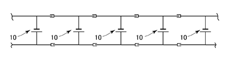
- FIG. 1 It is a conceptual diagram which shows the module stage to which the solar cell module was correctly wired. It is a conceptual diagram which shows the module stage to which the solar cell module was wired accidentally. It is a circuit diagram when a solar cell module is correctly wired. It is a conceptual diagram which shows a solar cell array.
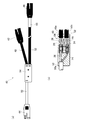
- (A) is a front view of a lead-in cable
- (b) is sectional drawing of the mold part of a lead-in cable.
- (A) is a top view of the connector whose both poles are male pieces
- (b) is a top view of the connector whose both poles are female pieces. It is a perspective view which shows the modification of the solar cell module shown in FIG.
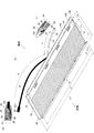
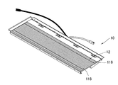
- the solar cell module 10 is provided with a solar cell panel 12, a front cover 102, a hook metal fitting 84, and the like on a base 82 configured by attaching a reinforcing heat insulating material 90 to a base material 70. Configured.
- the solar cell module 10 of the present embodiment is a tile-type solar cell module applied to the roof R of a newly built or already built house. As shown in FIGS. 1 and 2, the solar cell module 10 includes a solar cell panel 12, a terminal box 14 attached to the back surface of the solar cell panel 12, and two cables 16 and 18 extending from the terminal box 14. And connectors 20 and 22 connected to the cables 16 and 18, respectively.
- the solar cell module needs to have a total length in the longitudinal direction of 920 to 1200 [mm] and a total length in the short direction of 240 to 700 [mm].
- the solar cell panel to be mounted needs to have a length in the longitudinal direction of 900 to 1200 [mm] and a length in the short direction of 230 to 650 [mm].
- the solar cell module 10 is formed in a substantially rectangular surface as shown in FIGS. 1 and 2.
- the battery panel 12 occupies most of the area exposed to the outside when laid. Therefore, the size of the solar cell module 10 is approximately the same as the solar cell panel 12 or slightly larger than the solar cell panel 12.
- the total length LT of the solar cell module 10 is longer than the total length L1 of the solar cell panel 12 by the width of the groove-shaped flange portion 80.
- the solar cell module 10 of the present embodiment has a total length LT in the longitudinal direction smaller than 1200 [mm] in consideration of securing workability of installation work in a house while securing output.
- the solar cell module 10 does not include the lengths of the cables 16 and 18.
- the length L1 of the solar cell panel 12 is set to 900 to 1100 [9001] in consideration of the interval between general scaffolds installed at the time of laying the solar cell module 10 and the ease of handling by a construction worker. mm] range.
- the length (width) L4 in the short direction of the solar cell panel 12 is 250 to 320 [mm].
- the solar cell module 10 has a length L2 in the short direction of 240 to 480 [mm] in consideration of the size of a general flat roof tile.
- the length L2 is set to 280 in consideration of improving the photoelectric conversion efficiency by minimizing the shaded portion due to the sunshine condition while being approximately the same as the working width of a general flat roof tile. It is adjusted within the range of ⁇ 360 [mm].
- the solar cell panel 12 is formed in a substantially rectangular surface as shown in FIG. 1 and FIG.
- the solar cell panel 12 is laid in a posture in which the longitudinal direction is directed to the row direction of the house and the short side direction is directed to the ridge direction of the house.
- the solar battery panel 12 is formed by arranging a large number of strip-like solar battery cells 100 (hereinafter also simply referred to as battery cells 100) in a longitudinal direction so as to be in an electrically connected state. A voltage of about 100 [V] can be obtained.
- the solar cell panel 12 is a so-called tandem solar cell in which two or more types of photoelectric conversion layers are combined, and has high photoelectric conversion efficiency.
- a hybrid solar cell that is a tandem system is adopted as the battery panel 12. More specifically, as shown in FIG. 3, the battery panel 12 includes a transparent front electrode layer 104, first and second thin film photoelectric conversion units 106 a and 106 b (hereinafter referred to as amorphous materials) on a transparent substrate 102.
- a transparent front electrode layer 104 first and second thin film photoelectric conversion units 106 a and 106 b (hereinafter referred to as amorphous materials) on a transparent substrate 102.
- This is a so-called hybrid solar cell having a structure in which a metal back electrode layer 108, a sealing resin layer 110, and an organic protective layer 112 are sequentially laminated.
- the transparent substrate 102 is formed of, for example, a light-transmitting material such as a glass plate or a transparent resin film, and constitutes
- the transparent front electrode layer 104 is a single-layer or multilayer structure formed at a position adjacent to the transparent substrate 102.
- the transparent front electrode layer 104 is formed by laminating transparent and conductive oxides such as an ITO film, SnO 2 film, and ZnO film on the transparent substrate 102 in layers.
- the transparent front electrode layer 104 is formed using a conventionally known vapor deposition method, a CVD (Chemical Vapor Deposition) method, an EVD (Electrochemical Vapor Deposition) method, a vapor deposition method represented by a sputtering method, or the like.
- the thin film photoelectric conversion unit 106a includes an amorphous photoelectric conversion layer, and is provided at a position adjacent to the above-described transparent front electrode layer 104 in the light incident direction (downward in FIG. 3).
- the thin film photoelectric conversion unit 106a can have a structure in which, for example, a p-type silicon-based semiconductor layer, an i-type silicon-based amorphous photoelectric conversion layer, and an n-type silicon-based semiconductor layer are sequentially stacked from the transparent front electrode layer 104 side. .
- the thin film photoelectric conversion unit 106a preferably has a thickness of 0.01 ⁇ m to 0.5 ⁇ m, and more preferably has a thickness of 0.1 ⁇ m to 0.3 ⁇ m.
- the thin film photoelectric conversion unit 106b includes a crystalline photoelectric conversion layer, and is adjacent to the above-described thin film photoelectric conversion unit 106a in the light incident direction.
- the thin film photoelectric conversion unit 106b can have a structure in which, for example, a p-type silicon-based semiconductor layer, an i-type silicon-based crystalline photoelectric conversion layer, and an n-type silicon-based semiconductor layer are sequentially stacked from the thin film photoelectric conversion unit 106a side.
- the p-type silicon-based semiconductor layer, the i-type silicon-based crystalline photoelectric conversion layer, and the n-type silicon-based semiconductor layer constituting the thin film photoelectric conversion unit 106b are all formed by plasma CVD. It can be formed by a method or the like.
- the crystalline photoelectric conversion layer constituting the thin film photoelectric conversion unit 106b has a smaller light absorption coefficient than the amorphous photoelectric conversion layer constituting the thin film photoelectric conversion unit 106a described above. Therefore, the thickness of the crystalline thin film photoelectric conversion unit 106b is preferably about several to ten times the thickness of the amorphous thin film photoelectric conversion unit 106a. More specifically, the thin film photoelectric conversion unit 106b preferably has a thickness of 0.1 ⁇ m to 10 ⁇ m, and more preferably has a thickness of 0.1 ⁇ m to 5 ⁇ m.
- the p-type semiconductor layers constituting the photoelectric conversion units 106a and 106b described above are formed, for example, by doping silicon or a silicon alloy such as silicon carbide or silicon germanium with p-conductivity determining impurity atoms such as boron or aluminum. be able to.
- the amorphous photoelectric conversion layer and the crystalline photoelectric conversion layer can be formed of an amorphous silicon semiconductor material and a crystalline silicon semiconductor material, respectively.
- the amorphous photoelectric conversion layer and the crystalline photoelectric conversion layer can be formed of intrinsic semiconductor silicon (such as silicon hydride), silicon alloy such as silicon carbide and silicon germanium, or the like.
- the amorphous photoelectric conversion layer and the crystalline photoelectric conversion layer may have any photoelectric conversion function.
- n-type semiconductor layer of the amorphous photoelectric conversion layer or the crystalline photoelectric conversion layer is formed by doping silicon or a silicon alloy such as silicon carbide or silicon germanium with an n-conductivity determining impurity atom such as phosphorus or nitrogen. be able to.
- the above-described thin film photoelectric conversion units 106a and 106b have different absorption wavelength ranges. Specifically, when the photoelectric conversion layer of the thin film photoelectric conversion unit 106a is made of amorphous silicon, the light component of about 550 nm can be absorbed most efficiently, whereas the thin film photoelectric conversion unit 106b When the photoelectric conversion layer is made of crystalline silicon, a light component of about 900 nm can be absorbed most efficiently.
- the metal back electrode layer 108 is provided at a position adjacent to the thin film photoelectric conversion unit 106b in the traveling direction of incident light.
- the metal back electrode layer 108 is made of silver, aluminum, or the like, and is a layer formed to a thickness of about 200 nm to 400 nm by a conventionally known vapor deposition method, sputtering method, or the like.
- a transparent conductive thin film (not shown) made of a non-metallic material such as ZnO is appropriately disposed between the metal back electrode layer 108 and the thin film photoelectric conversion unit 106b in consideration of improvement in adhesion between them. Can be provided.
- the metal back electrode layer 108 reflects light incident from the transparent substrate 102 and passing through the thin film photoelectric conversion units 106a and 106b, and enters the thin film photoelectric conversion units 106a and 106b. It also has a function as a reflective layer for re-incidence.
- the solar cell module 10 has an organic protective layer via a sealing resin layer 110 at a position adjacent to the metal back electrode layer 108 described above in the traveling direction of incident light, that is, a position on the back side when installed in a house or the like. 112 is formed.
- the sealing resin layer 110 is a layer that bonds the organic protective layer 112 and the metal back electrode layer 108, for example, EVA (ethylene / vinyl acetate copolymer), PVB (polyvinyl butyral), PIB (polyisobutylene). And silicone resin.
- the organic protective layer 112 is a layer that seals the back side of the solar cell module 10.
- the organic protective layer 112 is, for example, a fluororesin film such as a polyvinyl fluoride film, an insulating film excellent in moisture resistance and water resistance, such as a film made of PET (polyethylene terephthalate), or a laminate of these.
- a fluororesin film such as a polyvinyl fluoride film
- an insulating film excellent in moisture resistance and water resistance such as a film made of PET (polyethylene terephthalate), or a laminate of these.
- PET polyethylene terephthalate
- a structure in which a metal foil made of aluminum or the like is sandwiched between these films can be suitably employed.
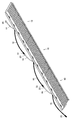
- the solar cell module 10 includes a plurality of thin films formed by laminating as described above by dividing the thin film into first and second divided grooves 114 a and 114 b and connection grooves 116.
- a battery cell 100 is formed. That is, the first and second divided grooves 114a and 114b and the connection groove 116 are formed between the adjacent battery cells 100 with the transparent front electrode layer 104, the thin film photoelectric conversion units 106a and 106b, the metal back electrode layer 108, and the like. It is provided so that the thin film to comprise may be divided
- the first and second divided grooves 114a and 114b and the connection groove 116 are each linear, and are formed so as to extend along the direction perpendicular to the paper surface in FIG. 3, that is, the short direction of the solar cell module 10. Has been.
- the first and second divided grooves 114a and 114b and the connection groove 116 are formed to be substantially parallel to each other.
- the first dividing groove 114 a is provided so as to divide the transparent front electrode layer 104 for each battery cell 100.
- the first dividing groove 114 a is an groove having an opening at the interface between the transparent front electrode layer 104 and the thin film photoelectric conversion unit 106 a and having the surface of the transparent substrate 102 as a bottom surface.
- the transparent front electrode layer 104 of the battery cell 100 is made of another battery cell 100 provided at a position adjacent to the longitudinal direction of the solar battery module 10 by amorphous silicon or the like embedded in the first dividing groove 114a.
- the transparent front electrode layer 104 is electrically insulated.
- the second dividing groove 114b is a groove that defines a boundary between adjacent battery cells 100.
- the second dividing groove 114b is provided at a position away from the first dividing groove 114a in the longitudinal direction of the solar cell module 10.
- the second dividing groove 114 b is formed to divide the thin film photoelectric conversion units 106 a and 106 b and the metal back electrode layer 108 for each battery cell 100.
- the second dividing groove 114 b has an opening at the interface between the metal back electrode layer 108 and the sealing resin layer 110, and the surface of the transparent front electrode layer 104 is the bottom surface.
- a resin constituting the sealing resin layer 110 such as the above-described EVA (ethylene / vinyl acetate copolymer) is embedded in the second dividing groove 114b. Therefore, the metal back electrode layer 108 of the battery cell 100 is electrically insulated from the metal back electrode layer 108 of another battery cell 100 provided at an adjacent position by the resin embedded in the second dividing groove 114b. ing.
- connection groove 116 is provided between the first and second divided grooves 114a and 114b.
- the connection groove 116 is a groove that divides the thin film photoelectric conversion units 106 a and 106 b for each battery cell 100.
- the connection groove 116 has an opening at the interface between the thin film photoelectric conversion unit 106 b and the metal back electrode layer 108, and the surface of the transparent front electrode layer 104 is the bottom surface.
- a metal material constituting the metal back electrode layer 108 such as silver or aluminum is embedded in the connection groove 116, and one metal back electrode layer 108 and the other transparent front electrode layer 104 of the adjacent battery cell 100 are connected.
- Each battery cell 100 has a width (short side) L3 of 7 to 12 [mm] from the viewpoint of balance between power generation area and electrode resistance, accuracy and ease of manufacturing, and minimizing output variations.
- the width L3 is more preferably 8 to 10 [mm].
- each battery cell 100 has a long side length slightly shorter than the length L4 in the short direction of the battery panel 12, and is about 3/4 of the length L2. Therefore, each battery cell 100 has a belt-like appearance when viewed from the transparent substrate 102 side.
- Each battery cell 100 is a tandem (hybrid) solar cell including thin film photoelectric conversion units 106a and 106b, and is configured by one unit by adding the open-circuit voltages of the two units.
- the voltage is higher than that of the solar cell, and the open circuit voltage is in the range of 1.2 to 1.5 [V].
- the battery panel 12 includes about 50 to 150 battery cells 100 connected in series, and is configured to output an open circuit voltage of 100 to 180 [V] as a whole. In the battery panel 12 of this embodiment, a large number of battery cells 100 are connected in series so that an open circuit voltage of about 100 [V] can be output as a whole.
- the battery panel 12 is preferably formed so that the short circuit current value is in the range of 9 to 15 [mA / cm 2 ], and is formed in the range of 10 to 15 [mA / cm 2 ]. It is even more desirable.
- each battery cell 100 faces in the short direction of the battery panel 12, and the short side of each battery cell 100 faces in the long direction of the battery panel 12. Therefore, in the battery panel 12, the area of the part functioning as the connection part of each battery cell 100, specifically, the first and second divided grooves 114a and 114b and the connection groove 116 can be suppressed. Further, by arranging each battery cell 100 in the battery panel 12 as described above, a part of the battery panel 12 may be shaded, or dust or dirt may be deposited on the lower side (eave side) of the battery panel 12 or the like. Even if it is deposited, the so-called hot spot phenomenon can be prevented from occurring.
- the solar cell module 10 has a terminal box 14 and first and second cables 16 and 18 taken out from the terminal box 14 on the back side of the battery panel 12 described above.
- the terminal box 14 includes a positive electrode connection terminal (not shown) to which the positive electrode of the battery panel 12 is connected and a negative electrode connection terminal (not shown) to which the negative electrode of the battery panel 12 is connected. It has been.
- two plus side core wires 24, which are black coated conductors, are connected to the plus side electrode connection terminal, and a minus side core wire 26, which is a white sheathed conductor, is connected to the minus side electrode connection terminal. Are connected.
- the first and second cables 16 and 18 are used for electrical connection with other solar cell modules 10 when the solar cell module 10 is laid and the solar cell array 1 is constructed.
- the first cable 16 includes one plus side core wire 24 of the two plus side core wires 24 and 24 and one minus side core wire of the two minus side core wires 26 and 26. 26 is formed by bundling.
- the second cable 18 is formed by bundling the other plus-side core wire 24 of the two plus-side core wires 24 and 24 and the other minus-side core wire 26 of the two minus-side core wires 26 and 26. It has been done.
- the first cable 16 and the second cable 18 are different in color, and the first cable 16 has a plus-side core wire 24 and a minus-side core wire 26 arranged in a white insulating tube 16a.
- the second cable 18 has a positive core wire 24 and a negative core wire 26 arranged in a black insulating tube 18a.
- first cable 16 and the second cable 18 are long and short, one is long and the other is short. Specifically, the first cable 16 is shorter than the second cable 18.
- the total length of the first cable 16 is less than 50% of the length of the long side of the rectangular battery panel 12, and the total length of the second cable 18 is 50% of the length of the long side of the battery panel 12. That's it.
- the total length of the first cable 16 and the length of the second cable 18 is longer than the length of the long side of the solar cell panel 12.
- the second cable 18 protrudes from the long side (upper side) 150 on the ridge side of the solar cell module 10 toward the ridge side (upper side).
- the more recommended length X is 50% or more of the length L1 of the solar cell panel 12 and is longer than the length L4 in the short direction of the solar cell panel 12, and the length L1 of the solar cell panel 12 Shorter than.
- the length of the portion extended toward the outside of the second cable 18 when the length L1 in the longitudinal direction of the solar cell panel 12 and the length L4 in the short direction of the solar cell panel 12 are used.
- X is longer than (L1 / 2) and longer than L4.
- the more recommended length X of the second cable 18 is longer than the sum of (L1 / 4) and L4, and shorter than the sum of ((L1 / 4) ⁇ 3) and L4.
- the length X of the second cable 18 may be designed to adopt a length L2 instead of the length L4 in consideration of a connection margin.
- the length X of the portion extending toward the outside of the second cable 18 is (L1). / 2) and longer than L2.
- the more recommended length X of the second cable 18 is longer than the sum of (L1 / 4) and L2, and shorter than the sum of ((L1 / 4) ⁇ 3) and L2.
- the length Y of the part extended toward the outer side of the 1st cable 16 is shorter than the length X of the above-mentioned 2nd cable 18, and is shorter than (L1 / 2). Further, the length Y of the portion extending toward the outside of the first cable 16 is shorter than the length L4 of the solar cell panel 12 in the short direction.
- the length X of the first cable 16 may be designed to adopt a length L2 instead of the length L4 in consideration of a connection margin. That is, the length Y of the portion extended toward the outside of the first cable 16 is shorter than the length L2 of the solar cell module 10 in the short direction.
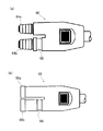
- a first connector 20 and a second connector 22 are provided at the respective ends of the first cable 16 and the second cable 18.
- the colors of the first connector 20 and the second connector are different, the structure is the same.
- the first connector 20 is white and the second connector 22 is black.
- the first connector 20 and the second connector 22 include a pin-shaped terminal 28 and a socket-shaped terminal 30.
- the first connector 20 and the second connector 22 have a female piece 32 and a male piece 34, the pin-like terminal 28 is in the female piece 32, and the socket-like terminal 30 is in the male piece 34. is there.
- a plus-side core wire 24 is joined to the pin-like terminal 28 of the first connector 20, and a minus-side core wire 26 is joined to the socket-like terminal 30 of the first connector 20.
- a minus-side core wire 26 is joined to the pin-like terminal 28 of the second connector 22, and a plus-side core wire 24 is joined to the socket-like terminal 30 of the second connector 22. That is, in the first connector 20, the pin-shaped terminal 28 is a positive electrode and the socket-shaped terminal 30 is a negative electrode. On the other hand, in the second connector 22, the pin-shaped terminal 28 is a negative electrode, and the socket-shaped terminal 30 is a positive electrode. Therefore, the first connector 20 and the second connector 22 are formed by fitting one female piece 32 and the other male piece 34 to connect one pin-like terminal 28 to the other socket-like terminal 30. It is possible to electrically connect the same poles in parallel.
- the base material 70 is a substantially rectangular plate, and is formed by bending one or more metal plates into a predetermined shape.
- the base material 70 is formed of a single metal plate, it can be easily processed and the manufacturing cost can be suppressed, and a structure having no joining portion can be provided, which is advantageous in terms of strength. It becomes. Therefore, considering these advantages, it is desirable that the base material 70 be formed by bending a single metal plate.
- a side fixing portion 76, a solar cell module 10 disposed adjacent to the ridge side (upper stage), and a stacking portion 78 on which an eaves side end of the general roof tile is stacked are formed.
- a groove-shaped flange 80 is formed on the side of the base material 70. It is preferable to use a metal plate such as a steel plate, aluminum, and stainless steel for the base material 70. In this embodiment, a galvalume steel plate is used.
- the cover attachment portion 72 is a portion to which a front cover 102 described later is attached, and is formed by bending the eaves side end portion of the base material 70 to the back surface side at a substantially right angle.
- the solar cell arrangement portion 74 is a planar portion on which the solar cell panel 12 is arranged, and is formed to have approximately the same size as the solar cell panel 12. As shown in FIG. 16, an opening 74 a for inserting the terminal box 14 of the solar cell panel 12 is provided at substantially the center of the solar cell arrangement portion 74.
- the solar cell panel 12 is mounted from the surface side of the substrate 70, and the terminal box 14, the cables 16, 18 and the connectors 20, 22 have openings 74a as shown in FIG. It is disposed on the back side of the base material 70.
- the ridge side fixing portion 76 is a portion that fixes the ridge side of the solar cell panel 12 arranged in the solar cell arrangement portion 74.
- the ridge-side fixing part 76 is formed by bending the base material 70 at a predetermined position to the front surface side at a substantially right angle, and by bending the base material 70 at the predetermined position from the base end of the rising part 76a.
- the rising portion 76a is a portion where the ridge side end surface of the solar cell panel 12 abuts, and the surface pressing portion 76b covers a part of the surface (light receiving surface) of the solar cell panel 12 and applies a pressing force from the surface side. Part.
- the loading portion 78 is a planar portion formed by folding the base material 70 toward the ridge side at a predetermined position from the base end of the surface pressing portion 76b of the ridge side fixing portion 76. As shown in FIG. 16, a through hole 78a for attaching a hook 84 to be described later is provided at a predetermined position of the stacking portion 78, and a solar cell module is provided at a predetermined position on the ridge side of the through hole 78a. A through hole 78b is provided for driving a screw for fixing 10 to the house.
- the loading portion 78 is in a portion excluding the upper surface of the solar cell panel 12.
- the reinforcing heat insulating material 90 is a foamed resin member that is attached to the back surface of the base material 70 in order to ensure the strength and heat insulating properties of the solar cell module 10.
- the reinforcing heat insulating material 90 extends in the eave direction from both ends of the girder direction reinforcing portion 92 extending in the girder direction along the long side of the base material 70 on the ridge side, and the girder direction reinforcing portion 92 along the short side of the base material 70. And an inclination direction reinforcing portion 94.
- the inclination direction reinforcing portion 94 is a portion that is stacked on the stacking portion 78 or the general roof tile of the solar cell module 10 disposed adjacent to the eave side (lower stage), and is formed thinner than the beam direction reinforcing portion 92. Has been.
- the reinforcement heat insulating material 90 is not attached to the whole back surface of the base material 70, but is arrange
- a terminal box 14 is disposed substantially at the center of the accommodation space 96.
- the accommodation space 96 can accommodate the wired cables 16 and 18.
- the cables 16 and 18 protrude from the long side 150 on the ridge side of the solar cell module 10, and the connectors of the cables 16 and 18 of the solar cell module 10 that are on the same row and adjacent to each other as will be described later. 20 and 22 are connected and the solar cell module 10 is connected in parallel.
- the connection work between the connectors 20 and 22 can be performed on the outer upper portion of the solar cell module 10.
- Two cable grooves 98 are provided on the surface of the reinforcing heat insulating material 90 opposite to the surface attached to the base material 70 of the beam direction reinforcing portion 92 as shown in FIG.
- the cable groove 98 penetrates from the ridge side of the reinforcing heat insulating material 90 to the eaves side, and connects the inside and outside of the accommodation space 96.
- One of the cable grooves 98 is a central groove 98a that is disposed substantially at the center of the girder-direction reinforcing portion 92, and the other is a side groove 98b that is disposed on the left and right of the central groove 98a with a predetermined distance from the central groove 98a. , 98b.
- the central groove 98 a and the terminal box 14 are arranged on substantially the same straight line, and the cables 16 and 18 extending from the terminal box 14 pass through the central groove 98 a from the accommodation space 96 to the ridge side. Has been pulled out of.
- the side grooves 98b and 98b are used for wiring with other solar cell modules 10 arranged adjacent to the upper and lower stages.
- step 1 the solar cell array 1 configured using the above-described solar cell module 10 will be described with reference to the work procedure when laying on the roof R of the house shown in FIG.
- step 2 lines, shapes, and dimensions necessary for the progress of the work are displayed on the roof R. Ink out is performed.
- step 2 vertical piers (sink bars) are attached at predetermined intervals, and in step 3, Hiroko Mai (tile) and horizontal piers (tiles) are attached. The horizontal piers are attached at predetermined climb intervals.
- step 4 after the blow-up preventing metal fitting for preventing the solar cell module 10 from blowing up is attached at a predetermined position, the operation shifts to step 5.
- step 5 the solar cell modules 10 are sequentially attached from the eaves side to the ridge side of the roof R, and the adjacent solar cell modules 10 are connected by the first cable 16 and the second cable 18. More specifically, as shown in FIG. 6, the solar cell module 10 is attached by forming the module stage 36 by arranging the short sides of the plurality of solar cell modules 10 next to each other in rows, and using screws or the like. This is performed by fixing each solar cell module 10 to the roof R. In the present embodiment, the module steps 36 are even steps (14 steps in FIG. 6) installed on the roof R.
- the solar cell module 10 is installed in the through-hole 78b of the stacking portion 78 in the construction screw 152 as shown in FIG. Is fixed to the house by being driven. At this time, the cables 16 and 18 of the solar cell module 10 are extended to the ridge side.
- the first connector 20 of one solar cell module 10 and the second connector 22 of the other adjacent solar cell module 10. are connected to each other, the two adjacent solar cell modules 10 and 10 can be electrically connected in parallel. That is, by connecting the white first connector 20 attached to the white first cable 16 and the black second connector 22 attached to the black second cable 18, the adjacent solar cell modules 10, Ten parallel connections are possible. Therefore, the solar cell module 10 of this embodiment connects all the solar cells included in the module stage 36 by connecting the left and right adjacent solar cell modules 10 and 10 using the first cable 16 and the second cable 18.
- the battery modules 10 can be sequentially connected in parallel (FIG. 10).
- the first cable 16 is formed shorter than the second cable 18. Therefore, in the solar cell module 10, the operator confirms the lengths of the first cable 16 and the second cable 18, so that the connectors 20 and 22 attached thereto are the first connector 20 or the second connector 20. Whether it is the connector 22 can be determined instantaneously.
- the total length of the first cable 16 is less than 50% of the length of the long side of the rectangular battery panel 12, and the total length of the second cable 18 is It is 50 percent or more of the length of the long side of the battery panel 12. Therefore, as shown in FIG. 8, the connectors 20, 20 attached to the first cable 16 cannot be connected to each other between the solar cell modules 10, 10 adjacent to each other with their short sides abutted. Therefore, the solar cell module 10 of the present embodiment can reliably prevent erroneous connection between the first connectors 20 and 20 between the adjacent solar cell modules 10 and 10.
- the first cable 16 is white and the second cable 18 is black. Therefore, the solar cell module 10 allows the operator to easily determine the types of the connectors 20 and 22 attached thereto by confirming the colors of the first cable 16 and the second cable 18.
- the solar cell module 10 is formed such that the first connector 20 is white and the second connector 22 is black, and the first connector 20 and the second connector 22 are different in color. Therefore, in the solar cell module 10 of the present embodiment, the operator can quickly determine the types of the connectors 20 and 22 by confirming the colors of the connectors 20 and 22 of the solar cell module 10. Therefore, the solar cell module 10 of the present embodiment allows a worker to select an appropriate connector quickly and has few wiring misconnections and high work efficiency.
- the 1st cable 16 and the 2nd cable 18 have protruded outside from the ridge side center of the solar cell module 10 like FIG. 1 in the solar cell module 10, in the state which fixed the solar cell module 10 to the roof
- the cables 16 and 18 can be connected. That is, even if the solar cell module 10 of this embodiment is fixed to the roof with a nail or the like, the first cable 16 and the second cable 18 are outside the main body portion of the solar cell module 10 as shown in FIGS. Out. Therefore, in this embodiment, after fixing the solar cell module 10 to a roof with a nail etc., it can connect.
- the cables 16 and 18 are connected for each stage.
- the solar cell module 10 since the solar cell module 10 is attached from the eaves side, the solar cell module 10 is first fixed to the eaves or the step in the vicinity of the eaves, and then the cables 16, 18 are sequentially connected. The connection work is performed on the upper side of the solar cell modules 10 arranged in a row of the corresponding stages, and the connected cables 16 and 18 are solar cell modules arranged in a row of the corresponding stages as shown in FIG. 10 is placed on the upper side. Subsequently, the second-stage solar cell module 10 is fixed. Here, the second-stage solar cell module 10 is placed on the stacking portion 78 of the first-stage solar cell module 10 on the eaves side. Therefore, the second-stage solar cell module 10 is covered on the cables 16 and 18 of the first-stage solar cell module 10 as shown in FIG. The cables 16 and 18 of the solar cell module 10 are accommodated.
- the solar battery module 10 is attached to the module stage 36 in the second and subsequent stages by placing the front cover 102 of the solar battery module 10C arranged in the upper stage on the eaves side.
- the locking piece 108 of the front cover 102 of 10C is inserted into a gap 156 formed between the engaging portion 88 of the hook metal fitting 84 of the solar cell module 10D and the surface of the stacking portion 78 of the base material 70, and the solar cell module. It is performed by pulling up the entire 10C to the building side and engaging the solar cell module 10C and the solar cell module 10D.
- the sealing member 154 is attached to the locking piece 108 of the solar cell module 10 ⁇ / b> C, and the locking piece 108 is inserted into the gap 156 between the engaging portion 88 of the hook metal 84 and the base material 70. Since the sealing material 154 is disposed in the gap 156 without a gap, rattling at the engaging portion between the solar cell module 10C and the solar cell module 10D is prevented.
- the cables 16 and 18 of the lower solar cell module 10D are connected to the upper solar cell module 10D.
- the accommodation space 96 FIG. 23.
- the upper solar cell module 10C extends the cables 16 and 18 to the building side.
- the construction screw 152 is driven into the through hole 78b of the stacking portion 78 and fixed to the house.
- the solar cell modules 10 and 10 adjacent to the left and right are connected by cables 16 and 18 in the same procedure as the first module stage 36.
- all the solar cell modules 10 included in the module stage 36 can be connected in parallel.
- the solar cell array 1 formed by laying a large number of solar cell modules 10 includes odd-numbered module levels 36 a and 36 c and even-numbered module levels 36 b from the eaves side (lower side). 36d, the connection order of the first cable 16 and the second cable 18 is reversed left and right. That is, the odd-numbered module stages 36 a and 36 c connect the second connector 22 of the right solar cell module 10 and the first connector 20 of the left solar cell module 10 to connect the second cable 18 and the first The cable 16 is connected.
- the even-numbered module stages 36b and 36d are connected to the first cable 16 by connecting the first connector 20 of the right solar cell module 10 and the second connector 22 of the left solar cell module 10. The second cable 18 is connected.
- the odd-numbered module stages 36a and 36c and the even-numbered module stages 36b and 36d are connected, and the solar cell blocks 38a and 38b (hereinafter simply referred to as the battery block 38a). , 38b).
- the solar battery module 10a, 10c disposed at the left end of the odd-numbered module stages 36a, 36c is a solar cell disposed at the left end of the even-numbered module stages 36b, 36d.
- the second connectors 22 of the solar cell modules 10a and 10c and the first connectors 20 of the solar cell modules 10b and 10d are connected.
- the two cables 18 of the lower solar cell modules 10a and 10c are connected to the first cables 16 of the upper solar cell modules 10b and 10d, as described above,
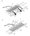
- the two cables 18 are passed through the back surface of the solar cell panel 12.
- the insertion route of the second cable 18 at this time is as shown in FIGS. 23 and 24, and passes through one of the side grooves 98b and 98b through the accommodation space 96 of the solar cell modules 10b and 10d.
- the front end side of the 2nd cable 18 is made to protrude further to the upper stage side of the upper stage side solar cell modules 10b and 10d, and is connected with the first cable 16 of the upper stage side solar cell modules 10b and 10d.
- the longer one of the two cables 16 and 18 (second cable 18) is used for the solar cell. Modules 10 are connected in parallel.
- the second cable 18 when the length X of the longer cable (second cable 18) is longer than the length L4 in the short direction of the solar cell panel 12, the second cable 18 is The solar cell module 10 belonging to the module stage 36 adjacent to the upper side of the roof can be submerged and extended further to the upper side of the solar cell module 10 belonging to the module stage 36 adjacent to the upper side.
- the second cable 18 when the length X of the longer cable (second cable 18) is longer than the length L2 in the short direction of the solar cell module 10, the second cable 18 is connected to the upper side of the roof.
- the solar cell module 10 belonging to the module stage 36 adjacent to the bottom of the solar battery module 10 belongs to the module stage 36, and extends further to the upper side of the solar cell module 10 belonging to the module stage 36 adjacent to the upper side so that it can be easily connected to other cables. Furthermore, in practice, as shown in FIG. 22, the space through which the cable 18 is inserted is limited, and the solar cell modules 10 are arranged in a staggered manner, so that the length X of the second cable 18 is the solar cell. The module 10 needs to be somewhat longer than the length L2 in the short direction. In the configuration shown in FIG. 22, the second cable 18 goes under the solar cell module 10 through the side groove 98 b provided in the reinforcing heat insulating material 90.
- the solar cell modules 10 belonging to the adjacent stages are arranged so as to be shifted by a length a. Furthermore, the length of the overlapping part of the solar cell modules 10 of the adjacent stage placed on the stacking portion 78 of the upper stage solar cell module 10 is b.
- the length of the second cable 18 is (L1 / 4) plus a
- the required length in the vertical direction is L2 minus b. Therefore, the required length of the second cable 18 is ((L1 / 4) plus a) plus (L2 minus b).
- L2 minus b is substantially equal to the length L4 of the solar battery panel 12 in the short direction. Therefore, the required length of the second cable 18 is ((L1 / 4) plus a) plus L4.
- 26 to 28 show the required length of the cable 18 by changing the shift amount a of the solar cell modules 10 belonging to adjacent stages.
- the longer cable 18 is required as the displacement amount a increases, but the longest cable 18 when the displacement amount reaches 3/4 of the total length L1 of the solar cell panel 12.
- Is required, and its length is the sum of ((L1 / 4) ⁇ 3) and L4. Further, considering the connection margin, it is the sum of ((L1 / 4) ⁇ 3) and L2.
- the length of the cable 18 is preferably equal to or less than the sum of ((L1 / 4) ⁇ 3) and L4, and considering the connection allowance, is preferably equal to or less than the sum of ((L1 / 4) ⁇ 3) and L2.
- the length Y of the part extended toward the outer side of the 1st cable 16 is shorter than the length X of the above-mentioned 2nd cable 18, and is shorter than (L1 / 2). Furthermore, the length Y of the part extended toward the outer side of the 1st cable 16 is shorter than the length L4 of the transversal direction of a solar cell panel. Therefore, the first cable 16 cannot pass under the upper solar cell module 10 and is not erroneously connected. In actuality, a margin for connection is necessary, and therefore, when the solar cell module 10 is shorter than the length L2 in the short direction, there is no erroneous connection.
- connection of the two cables 16 and 18 when the solar cell module 10 constituting the solar cell block 38 extends over a plurality of stages can be performed outside the solar cell module 10, workability is improved. high.
- the two connected cables 16 and 18 are accommodated in the accommodation space (gap part) 96 of the solar cell module 10 of one step as shown in FIG.
- all the solar cell modules 10 included in the module stage 36a and the module stage 36b are connected in parallel to form the battery block 38a. Further, all the solar cell modules 10 included in the module stage 36c and the module stage 36d are also connected in parallel to form a battery block 38b.
- the battery blocks 38a and 38b are each formed by electrically connecting 20 or more solar cell modules 10 in parallel. In addition, the battery blocks 38a and 38b have the same number of solar cell modules 10 constituting each.
- the battery blocks 38 a and 38 b formed as described above are electrically connected in series by the lead-in cable 40. Thereby, the solar cell array 1 is constructed.
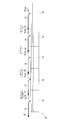
- the lead-in cable 40 includes a first series connector 42, a second series connector 44, an output connector 46, a first outdoor cable 48, a second outdoor cable 50, An inner cable 52 and a mold part 54 are provided.
- the first series connector 42 is connected to the first connector 20 of the solar cell module 10
- the second series connector 44 is connected to the second connector 22 of the solar cell module 10.
- the output connector 46 is connected to an indoor power conductor (not shown) and outputs power converted by the battery panel 12 of the solar cell module 10.
- the first outdoor cable 48 is connected to the first series connector 42
- the second outdoor cable 50 is connected to the second series connector 44.
- the indoor side cable 52 is connected to the output connector 46.
- the first series connector 42, the second series connector 44, and the output connector 46 have the same structure as the first connector 20 and the second connector 22 of the solar cell module 10.
- the first series connector 42 and the output connector 46 are black, and the second series connector 44 is white.
- the first outdoor cable 48, the second outdoor cable 50, and the indoor cable 52 are the plus side core wires 24 in the insulating tubes 48 a, 50 a, 52 a, similarly to the first cable 16 and the second cable 18 of the solar cell module 10. And one minus side core wire 26 is arranged.
- the insulation tubes 48a and 52a of the first outdoor cable 48 and the indoor cable 52 are black, and the insulation tube 50a of the second outdoor cable 50 is white.
- a white vinyl tape 56 is wound around the output connector 46 of the indoor cable 52. As a result, the indoor cable 52 and the output connector 46 can be discriminated instantaneously.
- the first outdoor cable 48, the second outdoor cable 50, and the indoor side cable 52 are connected to the mold portion 54. More specifically, the plus side core wire 24 of the first outdoor cable 48 and the minus side core wire 26 of the second outdoor cable 50 are electrically connected, and the minus side core wire 26 of the first outdoor cable 48 and the indoor side cable 52 are connected. The negative side core wire 26 is electrically connected, and the positive side core wire 24 of the second outdoor cable 50 and the positive side core wire 24 of the indoor side cable 52 are electrically connected.
- the white second series connector 44 of the lead-in cable 40 is a module stage constituting the battery block 38a. It is connected to the black second connector 22 of the solar cell module 10f at the right end of 36b.
- the black first serial connector 42 of the lead-in cable 40 is connected to the white first connector 20 of the solar cell module 10g at the right end of the module stage 36c constituting the battery block 38b.
- connection between the lead-in cable 40 and the battery blocks 38a and 38b it is only necessary to connect connectors of different colors as in the connection of the adjacent solar cell modules 10 and 10, and wiring misconnection is less likely to occur.
- connection of the lead-in cable 40 to the battery blocks 38a, 38b is merely a predetermined combination of the connectors 44, 22, 42, 20 and the work can be easily performed on the roof R. It can be carried out.
- the battery blocks 38a and 38b of the present embodiment are obtained by connecting a plurality of solar cell modules 10 that can obtain a voltage of about 100 [V] in one piece in parallel. Therefore, the voltage obtained from the entire battery blocks 38a and 38b is also about 100 [V].
- the solar cell array 1 is obtained by connecting two battery blocks 38a and 38b in series using a lead-in cable 40, and can output a voltage of about 200 [V], which is a rated voltage of various devices.
- a plurality of solar cell modules 10 are connected in parallel by connecting the solar cell modules 10 defined in the present application using the first cable 16 and the second cable 18 and connecting them with the lead-in cable 40.
- Solar cell solar cell blocks 38a and 38b can be made, and the two sets of solar cell solar cell blocks 38a and 38b can be connected in series.
- the above-described operation is simple and simple, and does not cause erroneous wiring, and many solar cell modules 10 can be laid on the roof.
- An output of approximately 200 [V] can be obtained from the output cable 52 of the lead-in cable 40.
- the wiring work can be carried out without a skilled electrician, for example, the wiring work can be easily completed by the hands of a high-level work expert such as a roof tiler or a carpenter.
- the voltage of 200 [V] or more can be generated by increasing the number of solar cells 100 of the solar cell panel 12 of the solar cell module 10 or the like. For example, a voltage of 200 [V] to 360 [V] can be generated.
- the terminal protection member 58 shown in FIG. 12 is attached to the first connector 20 and the second connector 22.
- the terminal protection member 58 has substantially the same structure as the first connector 20 and the second connector 22 of the solar cell module 10 except that the cable is not connected.
- the terminal protection member 58 is attached to the unused connectors 20 and 22, so that the unused first connector 20 and the terminals 28 and 30 of the second connector 22 are attached. It is possible to prevent dust and water from adhering.
- Step 6 When the work of Step 5 shown in FIG. 5 is completed as described above, the worker pulls the indoor cable 52 of the lead-in cable 40 into the house in Step 6. After that, construction of the surrounding tiles is performed (Step 7), and after the cleaning of the roof R (Step 8) is completed, after the inspection (Step 9) is performed, the lead-in cable 40 is bundled indoors (Step 10).
- the output connector 46 is connected to a connection box of a power conductor (not shown) (step 11), and a series of operations is completed.
- the solar cell module 10 of the present embodiment has a solar cell panel, the length of the solar cell panel in the longitudinal direction is 900 to 1100 [mm], and the short direction of the solar cell module 10
- the length of is 240 to 480 [mm]. That is, the solar cell module 10 has a total length WL in the longitudinal direction of 920 to 1200 [mm] and a total length L2 in the short direction of 240 to 480 [mm].
- the solar cell panel 12 has a longitudinal length L1 of 900 to 1100 [mm] and a lateral length L4 of 230 to 320 [mm]. Therefore, the solar cell module 10 can be easily carried and installed in a place where the workability of the laying work such as a roof of a house is poor.
- the solar cell module 10 of the present embodiment has a length in the longitudinal direction that is about twice as large as that of a general roof tile, and a length in the short side direction is about the same as that of the roof tile. Therefore, the above-described solar cell module 10 can be installed on the roof in a landscape orientation (long in the direction of the rows), and can be installed in the same manner as the tiles are arranged side by side in the lateral direction. Is suitable.
- the battery panel 12 is formed by arranging a plurality of band-shaped battery cells 100 having a width of 7 to 12 [mm] and electrically connecting them in series, and the configuration is uniform. Moreover, by forming in this way, the battery panel 12 has few individual differences in the output. Therefore, when the solar cell array 1 is constructed as described above, it is possible to minimize the output decrease of the entire solar cell array 1 due to individual differences in the output of each battery panel 12.
- each battery cell 100 constituting the solar battery panel 12 has a width of 7 to 12 [mm] and an open circuit voltage of 1.2 to 1.5 [V]. Therefore, when the size of the battery panel 12 or the solar cell module 10 is as described above, the output voltage can be set to a voltage suitable for configuring the solar cell array 1.
- the above-described solar battery cell 100 is a tandem type in which thin film photoelectric conversion units 106a and 106b are stacked, the energy of incident light can be utilized to the maximum extent possible.
- the solar cell 100 is not limited to a tandem type, and may be a single layer provided with only one of the thin film photoelectric conversion units 106a and 106b.
- each of the battery blocks 38a and 38b is configured by electrically connecting 20 or more solar cell modules 10 in parallel. Even if it falls, the influence which it has on the output fall of the whole solar cell array 1 is small. Therefore, the above-described solar cell array 1 can exhibit stable output performance without being substantially affected by a decrease in output in some of the solar cell modules 10.
- 20 or more solar cell modules 10 are connected in parallel to configure the battery blocks 38a and 38b is illustrated, but the present invention is not limited to this, and the battery blocks 38a and 38b are included.
- the number of the solar cell modules 10 to be configured may be less than 20.
- the solar cell array 1 described above was formed by connecting two battery blocks 38 in series.
- the present invention is not limited to this, and more battery blocks 38 are formed. These may be connected in series.
- the solar cell module 10 is not provided with a dividing line that divides the battery cell 100 so as to electrically insulate a region (effective power generation region) that generates power by receiving light, but the present invention is limited to this. Instead of this, as shown in FIG. 14, one or a plurality of dividing lines 118 extending in the longitudinal direction of the solar cell module 10 may be provided. According to such a configuration, even if a part of a specific battery cell 100 is shaded and no longer generates power, the solar cell module 10 can be prevented from being deteriorated or damaged by the hot spot phenomenon.
- the dividing line 118 is provided, individual differences occur in the output performance of each solar cell module 10 due to the hot spot phenomenon after the solar cell array 1 is laid, and as a result, the output balance of the solar cell blocks 38a and 38b is increased. It is possible to prevent the collapse and to effectively use the output of the solar cell module 10 functioning normally.
- the dividing line 118 may be provided so as to pass through any place of the battery cell 100, but the part that becomes the upper end side (building side) of the solar cell module 10 in the installed state in the house, or the lower end side (eave side) ), I.e., at positions located unevenly on the upper and lower ends in the short direction of the solar cell module 10. According to such a configuration, the hot spot phenomenon is prevented from occurring in a portion on the ridge side which is shaded by other solar cell modules 10 or roof tiles arranged on the upper side, or a portion on the eave side where dust or dust tends to accumulate. can do.
- the solar cell module 10 of this embodiment can be constructed by taking out the cables 16 and 18 toward the ridge side. Therefore, the solar cell module 10 can be easily laid from the eaves side of the house to the ridge side as is generally done when roofing tiles in the house. Therefore, the solar cell module 10 can be easily and orderly installed by, for example, an operator who is not familiar with electrical work.
- the solar cell array 100 of the present embodiment employs the solar cell module 10 described above, the cables 16 and 18 can be easily routed at the time of laying, and disconnection due to kinking of the cables 16 and 18 or the like can occur. Hard to happen.
- the solar cell array 100 of this embodiment can be constructed by taking out the cables 16 and 18 of each solar cell module 10 toward the ridge side without particularly handling the cables 16 and 17. Therefore, the solar cell array 100 of the present embodiment has the solar cell module 10 laid from the eave side of the house toward the ridge side, as is generally done when roofing tiles in a house. Thus, the cables 16 and 18 can be easily connected to each other.
- the accommodation space 96 provided in the base 82 is surrounded on three sides by the girder direction reinforcing portion 92 and the inclined direction reinforcing portions 94 and 94 of the reinforcing heat insulating material 90. Therefore, it is difficult for wind and rain to enter the housing space 96 from above (building side) and from the left and right in the state of laying in the house, and the terminal box 14 can be prevented from getting wet.
- the solar cell module 10 of the present embodiment can be ventilated through the open portion because the accommodation space 96 is open toward the eave facing side 162 side. Therefore, even if the terminal box 14 becomes high temperature due to energization, heat does not stay in the accommodation space 96 and the inside of the accommodation space 96 can be maintained at an appropriate temperature condition.
- the solar cell module 10 of the present embodiment is provided with a gap 168 around the terminal box 14 in the accommodation space 96. Therefore, the solar cell module 10 of the present embodiment can reliably prevent problems such as the heat generated in the terminal box 14 being trapped in the accommodation space 96 and the terminal box 14 being damaged or damaged by this heat. it can.
- the beam direction reinforcing portion 92 of the reinforcing heat insulating material 90 is made of foamed resin. Therefore, even if the cables 16 and 18 do not pass through the cable groove 98 provided in the girder direction reinforcing portion 92 and are sandwiched between the upper surface of the house and the girder direction reinforcing portion 92, the cables 16 and 18 An excessively large load can be prevented from acting. Therefore, the solar cell module 10 can reliably prevent inconveniences such as disconnection of the cables 16 and 18.
- FIG. 1 is a perspective view of a tile-type solar cell module employed in an embodiment of the present invention.
- 4 is a cross-sectional view of the connector of the solar cell module of FIG.
- the tile-type solar cell module 10 is an integrated solar cell, and a plurality of solar cells are formed inside to constitute one solar cell as a whole. That is, the tile-type solar cell module 10 is formed by laminating a conductive film or a semiconductor film on a glass substrate, and further providing a plurality of grooves in the glass substrate to divide it into a large number of unit cells (cells), and electrically connecting each cell in series. It is a thing.
- the tile-shaped solar cell module 10 has a rectangular shape as shown in the figure, and two cables 16 and 18 are extended from the central portion in the longitudinal direction. Further, connectors 20 and 22 are connected to the cables 16 and 18, respectively.
- the cables 16 and 18 are long and short, one is long and the other is short. Specifically, the long cable 18 has a total length of 50% or more of the total length of the roof tile-type solar cell module 10, and the short cable 16 has a total length of 50% of the total length of the roof tile-type solar cell module 10. Less than a percent.
- the cables 16 and 18 are different in color.
- Each of the cables 16 and 18 has two systems of electrically conductive wires 24 and 26 (a plus side core wire 24 and a minus side core wire 26). More specifically, it is a cable in which two coated conductors 24 and 26 are arranged in the same insulating tube.
- Connectors 20 and 22 are connected to the two cables 16 and 18, respectively.
- the connectors 20 and 22 are different in color but have the same structure, and have two terminals 28 and 30 (a pin terminal 28 and a socket terminal 30) as shown in FIG.
- one pin-shaped terminal 28 is a pin
- the other socket-shaped terminal 30 is a socket.
- the connectors 20 and 22 have a female piece 32 and a male piece 34, the pin-like terminal 28 is in the female piece 32, and the socket-like terminal 30 is in the male piece 34.
- the connectors 20 and 22 can be connected to each other, and one female piece 32 and the other male piece 34 are joined. At that time, one pin-shaped terminal 28 and the other socket-shaped terminal 30 are connected inside each female piece 32 and male piece 34.
- the two covered conductors 24 and 26 of the two cables 16 and 18 are respectively connected to the positive electrode and the negative electrode of the solar cell (hereinafter referred to as a solar cell) in the roof tile solar cell module 10. Yes. That is, one coated conductor 24 in the cable 18 is connected to the positive electrode of the solar cell, and the other coated conductor 26 is connected to the negative electrode of the solar cell. Similarly, one coated conductor 24 in the cable 16 is connected to the positive electrode of the solar cell, and the other coated conductor 26 is connected to the negative electrode of the solar cell. Therefore, one of the two terminals 28 and 30 of the connector 22 is connected to the positive electrode of the solar cell, and the other coated conductor is connected to the negative electrode of the solar cell.
- one of the two terminals 28 and 30 of the connector 20 is connected to the positive electrode of the solar cell, and the other coated conductor is connected to the negative electrode of the solar cell.
- the polarities of the two terminals 28 and 30 of the connectors 20 and 22 are compared, they are opposite to each other. That is, in one connector 20, the pin-shaped terminal 28 is a positive electrode and the socket-shaped terminal 30 is a negative electrode, whereas in the other connector 22, the pin-shaped terminal 28 is a negative electrode and the socket-shaped terminal 30 is a positive electrode. is there.
- FIG. 7 is a conceptual diagram when the tile-type solar cell module is accurately wired.
- FIG. 8 is a conceptual diagram when the tile-type solar cell module is mistakenly wired.
- FIG. 9 is a circuit diagram when the tile-type solar cell module is correctly wired.
- the tile-type solar cell module 10 described above is arranged side by side on a structure such as a roof. Then, the connectors 20 and 22 of the adjacent tile type solar cell modules 10 are connected. When attention is paid to one tile-type solar cell module 10, the connector 22 of the tile-type solar cell module 10 and the connector 20 of the tile-type solar cell module 10 on the left are connected.
- the connector 20 of the tile-type solar cell module 10 and the connector 22 of the tile-type solar cell module 10 on the right side are connected. If it demonstrates paying attention to the length of a cable, the connector 22 of the long cable 18 of the said tile type solar cell module 10 and the connector 20 of the short cable 16 of the tile type solar cell module 10 on the left side will be connected. Further, the connector 20 of the short cable 16 of the tile-type solar cell module 10 and the connector 22 of the long cable 18 of the tile-type solar cell module 10 on the right side are connected. As a result, the solar cells are connected in parallel as shown in FIG.
- the other connectors 20 cannot be physically connected, so the operator notices the connection error. It becomes. That is, the other connector 20 is connected to a short cable 16, and the short cable 16 is less than half of the total length of the roof tile solar cell module 10. Moreover, since the cables 16 and 18 are extended from the center part of the tile-shaped solar cell module 10, even if it is going to connect the short cables 16, length is not enough and both cannot be connected. Therefore, the tile-type solar cell module 10 of the present embodiment cannot cause wiring errors.
Abstract
Description
特許文献3の図25には、太陽電池パネルの長辺側に導線が延出された構成が開示されている。しかしながら、特許文献3に示された太陽電池モジュールは、導線が短く、且つ太陽電池パネルと基材62の位置関係から考えて、導線が太陽電池モジュールの外に延出されるものではない。
また特許文献3に示された太陽電池モジュールは、導線が2本であり、一方がプラス線であり、他方がマイナス線である。
特許文献4,5には、太陽電池モジュールの軒側から2本のケーブルが出ている図面が開示されている。特許文献4,5に開示された構成は、2本のケーブルはいずれも単芯であって太陽電池モジュール同士を直列接続するものである。
特許文献4に記載された構成でも、同文献の図20,21に開示された様に、自己の太陽電池モジュールの裏面または同列(同段)の太陽電池モジュールの裏面に収納される。
特許文献5では、太陽電池モジュールを平置き状に配置するものであって重ねない。特許文献5についても、大半のケーブルは自己の太陽電池モジュールの裏面に配される。
特許文献6には、太陽電池モジュールの棟側から2本のケーブルが延出した構成が開示されている。特許文献6に開示の構成では、配線は、太陽電池モジュールが配列された部位とは別の部位で行われている。
特許文献7に記載の発明では、太陽電池モジュールの棟側から2本のケーブルが出ており、このケーブルが隣接する段に属する太陽電池モジュールの裏面側で接続された図面が開示されている。特許文献8に開示された構成では、2本のケーブルはいずれも単芯であって太陽電池モジュール同士を直列接続するものである。特許文献7に記載の発明は、偏平な形状のコネクタを使用することを特徴としている。特許文献7に記載された太陽電池モジュールは、本体部分が平板状であり、その底に偏平な形状のコネクタを配置する。
特許文献7に開示された太陽電池モジュールは長方形であり、2本のケーブルはその短手方向の辺から外側に延出されている。 In addition, there are Patent Documents 3 to 9 as prior arts related to the present invention.
FIG. 25 of Patent Document 3 discloses a configuration in which a conducting wire is extended to the long side of the solar cell panel. However, the solar cell module disclosed in Patent Document 3 has a short conducting wire, and the conducting wire is not extended out of the solar cell module in view of the positional relationship between the solar cell panel and the
Moreover, the solar cell module shown by patent document 3 has two conducting wires, one is a plus wire and the other is a minus wire.
Even the configuration described in
In patent document 5, a solar cell module is arrange | positioned flatly and it does not overlap. Also in Patent Document 5, most of the cables are arranged on the back surface of the own solar cell module.
Patent Document 6 discloses a configuration in which two cables extend from the ridge side of the solar cell module. In the configuration disclosed in Patent Document 6, the wiring is performed at a site different from the site where the solar cell modules are arranged.
In the invention described in Patent Document 7, two cables are provided from the ridge side of the solar cell module, and a drawing in which the cables are connected on the back side of the solar cell module belonging to the adjacent stage is disclosed. In the configuration disclosed in Patent Document 8, each of the two cables is a single core, and the solar cell modules are connected in series. The invention described in Patent Document 7 is characterized by using a flat connector. In the solar cell module described in Patent Document 7, the main body portion has a flat plate shape, and a flat connector is disposed on the bottom thereof.
The solar cell module disclosed in Patent Document 7 is rectangular, and the two cables extend outward from the short side.
特許文献9は、太陽電池モジュールに4本のケーブルが接続された構成が開示されている。また特許文献9に開示された構成では、ケーブルに長短がある。さらにケーブルを色違にすることも開示されている。
特許文献9に記載された構成でも、同文献の図7に開示された様に、接続されたケーブルは自己の太陽電池モジュールの裏面または同列(同段)の太陽電池モジュールの裏面に収納される。
Patent Document 9 discloses a configuration in which four cables are connected to a solar cell module. In the configuration disclosed in Patent Document 9, the cable is long or short. Furthermore, it is also disclosed that the cables are different colors.
Even in the configuration described in Patent Document 9, as disclosed in FIG. 7 of the same document, the connected cable is accommodated on the back surface of the own solar cell module or the back surface of the solar cell module in the same row (same stage). .
本発明の太陽電池モジュールは、長手方向の全長が920乃至1200[mm]であって短手方向の全長が240乃至700[mm]である。
そして前記太陽電池モジュールは太陽電池パネルを備え、当該太陽電池パネルは、長手方向の長さが900乃至1200[mm]であって短手方向の長さが230乃至650[mm]の略長方形の面状に形成されたものであり、当該太陽電池パネルの長手方向が家屋の桁行方向に向き、前記太陽電池パネルの短手方向が家屋の棟行方向に向くように設置されるものである。
前記太陽電池パネルは、複数の太陽電池セルを有し、開放電圧が100乃至180[V]となるように前記太陽電池セルを電気的に直列接続したものであり、
前記太陽電池セルが、帯状で短辺の長さが7乃至12[mm]のものであり、前記太陽電池パネルの短手方向に長辺が向き、前記太陽電池パネルの長手方向に短辺が向いた状態で、前記太陽電池パネルの長手方向に並ぶように設けられている。
太陽電池パネルの正極に電気的に導通した二本のプラス側の導線と、前記太陽電池パネルの負極に電気的に導通した二本のマイナス側の導線とを備えている。
また前記二本のプラス側の導線と、前記二本のマイナス側の導線はいずれも太陽電池モジュールの長手方向の辺から外側に向かって延出されている。
前記太陽電池モジュールの裏面には、他の太陽電池パネルの二本のプラス側の導線と二本のマイナス側の導線を収容する空隙部が設けられている。
太陽電池モジュールの上面に、他の太陽電池モジュールの一部を載置する積載部が設けられている。 The present invention provided to solve the above-mentioned problems is a solar cell module installed on a roof of a house, and a solar cell block formed by electrically connecting the plurality of solar cell modules in parallel. A solar cell module for forming a solar cell array formed by connecting a plurality of components in series electrically.
The solar cell module of the present invention has a total length in the longitudinal direction of 920 to 1200 [mm] and a total length in the short direction of 240 to 700 [mm].
The solar cell module includes a solar cell panel, and the solar cell panel has a substantially rectangular shape with a longitudinal length of 900 to 1200 [mm] and a lateral length of 230 to 650 [mm]. It is formed in a planar shape, and is installed so that the longitudinal direction of the solar cell panel is directed to the row direction of the house, and the short direction of the solar cell panel is directed to the row direction of the house.
The solar cell panel has a plurality of solar cells, and the solar cells are electrically connected in series so that the open circuit voltage is 100 to 180 [V].
The solar cell has a strip shape and a short side length of 7 to 12 [mm], the long side faces in the short direction of the solar cell panel, and the short side in the longitudinal direction of the solar cell panel. In a state of facing, it is provided so as to be aligned in the longitudinal direction of the solar cell panel.
Two positive-side conductors electrically connected to the positive electrode of the solar cell panel and two negative-side conductors electrically connected to the negative electrode of the solar cell panel.
The two plus-side conductors and the two minus-side conductors both extend outward from the longitudinal sides of the solar cell module.
On the back surface of the solar cell module, there is provided a gap that accommodates two plus-side conductors and two minus-side conductors of another solar cell panel.
On the upper surface of the solar cell module, a stacking unit for placing a part of another solar cell module is provided.
なお太陽電池モジュールの全長にはケーブルの長さを含まない。 In the solar cell module of the present invention, the length of the built-in solar cell panel in the longitudinal direction is 900 to 1200 [mm], and it is easily carried into a place where workability of laying work such as a roof of a house is poor. Can be constructed. Also, the total length of the solar cell module itself is 920 to 1200 [mm], the total length in the short direction is 240 to 700 [mm], and the solar cell module of the present invention generally has a length in the longitudinal direction. Since it is about twice the size of roof tiles used, it can be installed in houses with work efficiency that is not much different from that of roofing tiles.
The total length of the solar cell module does not include the cable length.
そしてケーブルを接続した後に、隣接する段に属する太陽電池モジュールを積載部に載置することにより、先に接続したケーブルの上に隣接する段の太陽電池モジュールを載置することができる。
また本発明では、ケーブルを接続した後に、隣接する段に属する太陽電池モジュールを設置することにより、先に接続したケーブルを、隣接する段の太陽電池モジュールの空隙部に収容することができる。 In the present invention, the solar cell module is substantially rectangular, and the four conductors are all extended outward from the sides in the longitudinal direction of the solar cell module. Can be done outside the area. In addition, the solar cell module of the present invention is provided with a stacking portion on the top surface for mounting a part of another solar cell module.
And after connecting a cable, the solar cell module of the adjacent stage can be mounted on the cable connected previously by mounting the solar cell module which belongs to the adjacent stage on a loading part.
Moreover, in this invention, after connecting a cable, the cable connected previously can be accommodated in the space | gap part of the solar cell module of an adjacent stage by installing the solar cell module which belongs to an adjacent stage.
また上記した太陽電池モジュールの敷設構造では、作業者がコネクタを誤接続することはない。すなわち上記した太陽電池モジュールの敷設構造では、この様にケーブルの長さに長短があるので、太陽電池モジュールを列状に並べたとき、短いケーブルが接続されたコネクタ同士は長さ不足の状態であって接続させることができない。そのため屋根の上等に太陽電池モジュールを敷設した際に、隣接する太陽電池モジュールの短いケーブル同士を接続することは物理的にできず、作業者がコネクタを誤接続することはない。 In the solar cell module laying structure described above, the connector of the adjacent solar cell module is joined to the connector to which the long cable is connected and the connector to which the short cable is connected. In the laying structure of the solar cell module described above, a state where the connector to which the long cable is connected and the connector to which the short cable is connected is joined is a regular joined state. In the laying structure described above, when the long cable connector and the short cable connector of the adjacent solar cell modules are joined in this way, the positive electrode side terminals and the negative electrode side terminals of both connectors are connected to each other, The solar cell modules are electrically connected in parallel.
Further, in the solar cell module laying structure described above, an operator does not erroneously connect the connector. In other words, in the solar cell module laying structure described above, since the length of the cable is long and short in this way, when the solar cell modules are arranged in a row, the connectors to which the short cables are connected are not sufficiently long. There is no connection. Therefore, when a solar cell module is laid on the roof or the like, short cables of adjacent solar cell modules cannot be physically connected to each other, and an operator does not erroneously connect the connectors.
また搭載される太陽電池パネルは、長手方向の長さが900乃至1200[mm]であって短手方向の長さが230乃至650[mm]であることが必要である。
次に太陽電池モジュール10及び太陽電池パネル12の推奨される大きさについて説明する。以下に説明する太陽電池モジュール10及び太陽電池パネル12の推奨される大きは、図1以下に示す実施例のサイズである。 The solar cell module needs to have a total length in the longitudinal direction of 920 to 1200 [mm] and a total length in the short direction of 240 to 700 [mm].
The solar cell panel to be mounted needs to have a length in the longitudinal direction of 900 to 1200 [mm] and a length in the short direction of 230 to 650 [mm].
Next, the recommended size of the
本実施形態の太陽電池モジュール10は、出力を確保しつつ、家屋への設置作業の作業性を確保することを考慮し、長手方向の全長LTが1200[mm]より小さいものとされている。ただし太陽電池モジュール10にはケーブル16,18の長さを含まない。
本実施形態では、太陽電池モジュール10の敷設施工時に設置される一般的な足場の間隔や、施工作業者の取り回しやすさ等を考慮し、太陽電池パネル12の長さL1が、900~1100[mm]の範囲とされている。
また太陽電池パネル12の短手方向の長さ(幅)L4は、250乃至320[mm]である。
また、太陽電池モジュール10は、一般的な平板瓦のサイズなどを考慮し、短手方向の長さL2が240~480[mm]の範囲とされている。本実施形態では、一般的な平板瓦の働き幅と同程度としつつ、日照条件によって陰になる部分を最小限に抑制することで光電変換効率を向上させることに配慮し、長さL2が280~360[mm]の範囲内に調整されている。 The
The
In the present embodiment, the length L1 of the
The length (width) L4 in the short direction of the
Further, the
またより推奨される長さXは、太陽電池パネル12の長さL1の50パーセント以上であり、且つ太陽電池パネル12の短手方向の長さL4よりも長く、太陽電池パネル12の長さL1よりも短い。
具体的には、太陽電池パネル12の長手方向の長さL1とし、太陽電池パネル12の短手方向の長さL4としたとき第二ケーブル18の外側に向かって延出された部分の長さXは(L1/2)よりも長く且つL4よりも長い。より推奨される第二ケーブル18の長さXは、(L1/4)とL4の合計よりも長く、((L1/4)×3)とL4の合計よりも短いものである。
また第二ケーブル18の長さXは、接続の余裕を考慮し、前記L4に代わってL2を採用した長さに設計してもよい。即ち太陽電池パネル12の長手方向の長さL1とし、太陽電池モジュール10の短手方向の長さL2としたとき第二ケーブル18の外側に向かって延出された部分の長さXは(L1/2)よりも長く且つL2よりも長い。より推奨される第二ケーブル18の長さXは、(L1/4)とL2の合計よりも長く、((L1/4)×3)とL2の合計よりも短いものである。 More specifically, as shown in FIG. 1, the
The more recommended length X is 50% or more of the length L1 of the
Specifically, the length of the portion extended toward the outside of the
The length X of the
さらに第一ケーブル16の外側に向かって延出された部分の長さYは、太陽電池パネル12の短手方向の長さL4よりも短い。
また第一ケーブル16の長さXは、接続の余裕を考慮し、前記L4に代わってL2を採用した長さに設計してもよい。即ち第一ケーブル16の外側に向かって延出された部分の長さYは、太陽電池モジュール10の短手方向の長さL2よりも短い。 Moreover, the length Y of the part extended toward the outer side of the
Further, the length Y of the portion extending toward the outside of the
The length X of the
積載部78は太陽電池パネル12の上面を除く部位にある。 The
The
また補強断熱材90の傾斜方向補強部94と家屋との間には隙間があるので、当該隙間にケーブル16,18が挿通される。 In the present embodiment, the
In addition, since there is a gap between the inclined
ケーブル16,18の接続は、段ごとに行われる。本実施形態では、軒側から太陽電池モジュール10を取り付けるから、最初に軒又は軒近傍の段に太陽電池モジュール10を固定し、その後に、各太陽電池モジュール10の棟側に突出したケーブル16,18を、順次接続する。接続作業は、当該段の列状に並べられた太陽電池モジュール10の上段側で行われ、接続されたケーブル16,18は、図22の様に当該段の列状に並べられた太陽電池モジュール10の上段側に置かれる。
続いて2段目の太陽電池モジュール10を固定する。ここで2段目の太陽電池モジュール10は、軒側を1段目の太陽電池モジュール10の積載部78上に載置される。そのため1段目の太陽電池モジュール10のケーブル16,18上に、図22の様に2段目の太陽電池モジュール10が被さり、2段目の太陽電池モジュール10の収容空間96に1段目の太陽電池モジュール10のケーブル16,18が収容される。 Moreover, since the
The
Subsequently, the second-stage
また接続しろを考慮すると、長い方のケーブル(第二ケーブル18)の長さXが太陽電池モジュール10の短手方向の長さL2よりも長い場合は、第二ケーブル18は、屋根の上部側に隣接するモジュール段36に属する太陽電池モジュール10の下を潜り、上部側に隣接するモジュール段36に属する太陽電池モジュール10のさらに上部側に延出して他のケーブルと容易に接続できる。
さらに実際上は、図22の様に、ケーブル18を挿通させる空間が限定されることと、太陽電池モジュール10が千鳥状に配されることから、第二ケーブル18の長さXは、太陽電池モジュール10短手方向の長さL2よりもある程度長くする必要がある。
図22に示す構成では、第二ケーブル18は、補強断熱材90に設けられたサイド溝98bを経て太陽電池モジュール10の下を潜る。また隣接する段に属する太陽電池モジュール10は、長さaだけずらして配されている。
さらに上部側の段の太陽電池モジュール10の積載部78に載置され、隣接する段の太陽電池モジュール10の重なり部分の長さは、bである。
図22に示す例で説明すると、第二ケーブル18の長さは、横引きされる長さが、(L1/4)プラスaであり、縦方向の必要長さは、L2マイナスbである。
そのため第二ケーブル18の必要長さは、((L1/4)プラスa)プラス(L2マイナスb)である。
ここで本実施形態では、L2マイナスbは、太陽電池バネル12の短手方向の長さL4と略等しい。そのため第二ケーブル18の必要長さは、((L1/4)プラスa)プラスL4である。 Here, in the
In consideration of the connection allowance, when the length X of the longer cable (second cable 18) is longer than the length L2 in the short direction of the
Furthermore, in practice, as shown in FIG. 22, the space through which the
In the configuration shown in FIG. 22, the
Furthermore, the length of the overlapping part of the
Referring to the example shown in FIG. 22, the length of the
Therefore, the required length of the
Here, in the present embodiment, L2 minus b is substantially equal to the length L4 of the
従ってケーブル18の長さは、((L1/4)×3)とL4の合計以下であり、接続しろを考慮すると((L1/4)×3)とL2の合計以下であることが望ましい。 26 to 28 show the required length of the
Therefore, the length of the
さらに第一ケーブル16の外側に向かって延出された部分の長さYは、太陽電池バネルの短手方向の長さL4よりも短い。そのため第一ケーブル16は、上段側の太陽電池モジュール10の下をくぐり抜けることができず、誤接続されることがない。
実際には接続しろが必要であるから、太陽電池モジュール10短手方向の長さL2よりも短い場合には、誤接続されることはない。 Moreover, the length Y of the part extended toward the outer side of the
Furthermore, the length Y of the part extended toward the outer side of the
In actuality, a margin for connection is necessary, and therefore, when the
そのため本発明によると、配線作業を、熟練した電気技術者でなくとも実施することができ、例えば、屋根瓦職人や大工といった高所作業熟練者の手によって簡単に配線作業を完了させることができる。
また太陽電池モジュール10の太陽電池パネル12の太陽電池セル100の数を増加させる等により、200[V]以上の電圧を発生させることができる。例えば、200[V]乃至360[V]の電圧を発生させることもできる。 As described above, a plurality of
Therefore, according to the present invention, the wiring work can be carried out without a skilled electrician, for example, the wiring work can be easily completed by the hands of a high-level work expert such as a roof tiler or a carpenter. .
Moreover, the voltage of 200 [V] or more can be generated by increasing the number of
即ち太陽電池モジュール10は長手方向の全長WLが920乃至1200[mm]であって短手方向の全長L2が240乃至480[mm]であり、
太陽電池パネル12は、長手方向の長さL1が900乃至1100[mm]であって短手方向の長さL4が230乃至320[mm]である。
そのため、太陽電池モジュール10は、家屋の屋根などのような敷設作業の作業性が悪い場所にも容易に搬入し、施工することができる。また、本実施形態の太陽電池モジュール10は、長手方向の長さが、一般的な瓦の2倍程度の大きさであり、短手方向の長さが瓦と同程度である。そのため、上記した太陽電池モジュール10は、横長(桁行方向に長い)の姿勢で屋根に配置することにより、瓦を横方向に順次並べて葺くのと同様の作業で設置でき、屋根への施工に適している。 As described above, the
That is, the
The
Therefore, the
図1は、本発明の実施形態で採用する瓦型太陽電池モジュールの斜視図である。図4は、図1の太陽電池モジュールのコネクタの断面図である。 Examples of the present invention will be further described below.
FIG. 1 is a perspective view of a tile-type solar cell module employed in an embodiment of the present invention. 4 is a cross-sectional view of the connector of the solar cell module of FIG.
すなわち瓦型太陽電池モジュール10は、ガラス基板に導電膜や半導体膜が積層され、さらにこれに複数の溝を設けて多数の単体電池(セル)に分割し、各セルを電気的に直列に接続したものである。 The tile-type
That is, the tile-type
またケーブル16,18にはそれぞれコネクタ20,22が接続されている。
ケーブル16,18は長さに長短があり、一方が長く、他方が短い。具体的には、長い方のケーブル18は、その全長が瓦型太陽電池モジュール10の全長の50パーセント以上であり、短い方のケーブル16は、その全長が瓦型太陽電池モジュール10の全長の50パーセント未満である。
またケーブル16,18は色が違う。ケーブル16,18はいずれも電気的に絶縁された2系統の導線24,26(プラス側芯線24,マイナス側芯線26)を有するものである。より具体的には、2条の被覆導線24,26が同一の絶縁チューブ内に配されたケーブルである。 The tile-shaped
Further,
The
The
2本の端子28,30の内、一方のピン状端子28は、ピンであり、他方のソケット状端子30は、ソケットである。
またコネクタ20,22は、雌片32と雄片34とを有し、前記したピン状端子28は、雌片32内にあり、ソケット状端子30は雄片34にある。
コネクタ20,22は、互いに接続可能であり、一方の雌片32と他方の雄片34とが接合される。そのとき、各雌片32と雄片34の内部では、一方のピン状端子28と他方のソケット状端子30とが接続される。
Of the two
The
The
したがって、コネクタ22の2本の端子28,30の一方は、太陽電池の正極に接続され、他方の被覆導線は太陽電池の負極に接続されている。同様にコネクタ20の2本の端子28,30の一方は、太陽電池の正極に接続され、他方の被覆導線は太陽電池の負極に接続されている。
ただしコネクタ20,22の2本の端子28,30の極性を比較すると、両者は反対極となっている。すなわち一方のコネクタ20では、ピン状端子28が正極であり、ソケット状端子30が負極であるのに対し、他方のコネクタ22では、ピン状端子28が負極であり、ソケット状端子30が正極である。 In the present embodiment, the two covered
Therefore, one of the two
However, when the polarities of the two
図7は、瓦型太陽電池モジュールを正確に配線した場合の概念図である。図8は、瓦型太陽電池モジュールを誤って配線した場合の概念図である。図9は、瓦型太陽電池モジュールを正確に配線した場合の回路図である。
上記した瓦型太陽電池モジュール10は、図5,7に示すように、横に並べて屋根等の構造物に敷設する。
そして隣接する瓦型太陽電池モジュール10のコネクタ20,22を接続する。一つの瓦型太陽電池モジュール10に注目すると、当該瓦型太陽電池モジュール10のコネクタ22と左隣の瓦型太陽電池モジュール10のコネクタ20とを接続する。また瓦型太陽電池モジュール10のコネクタ20と右隣の瓦型太陽電池モジュール10のコネクタ22とを接続する。
ケーブルの長短に注目して説明すると、当該瓦型太陽電池モジュール10の長いケーブル18のコネクタ22と左隣の瓦型太陽電池モジュール10の短いケーブル16のコネクタ20とを接続する。また瓦型太陽電池モジュール10の短いケーブル16のコネクタ20と右隣の瓦型太陽電池モジュール10の長いケーブル18のコネクタ22とを接続する。
その結果、図7に示すように、太陽電池が並列に接続される。 Next, the laying structure of the tile-type
FIG. 7 is a conceptual diagram when the tile-type solar cell module is accurately wired. FIG. 8 is a conceptual diagram when the tile-type solar cell module is mistakenly wired. FIG. 9 is a circuit diagram when the tile-type solar cell module is correctly wired.
As shown in FIGS. 5 and 7, the tile-type
Then, the
If it demonstrates paying attention to the length of a cable, the
As a result, the solar cells are connected in parallel as shown in FIG.
したがって本実施形態の瓦型太陽電池モジュール10は、配線の誤りが起きえない。 On the other hand, if the connection method is incorrect and the
Therefore, the tile-type
Claims (11)
- 家屋の屋根に複数設置される太陽電池モジュールであり、前記複数の太陽電池モジュールを電気的に並列接続することにより形成された太陽電池ブロックを複数、電気的に直列接続することにより形成される太陽電池アレイ構成用の太陽電池モジュールであって、
前記太陽電池モジュールは長手方向の全長が920乃至1200[mm]であって短手方向の全長が240乃至700[mm]であり、
前記太陽電池モジュールは太陽電池パネルを備え、当該太陽電池パネルは、長手方向の長さが900乃至1200[mm]であって短手方向の長さが230乃至650[mm]の略長方形の面状に形成されたものであり、当該太陽電池パネルの長手方向が前記家屋の桁行方向に向き、前記太陽電池パネルの短手方向が前記家屋の棟行方向に向くように設置されるものであり、
前記太陽電池パネルが、複数の太陽電池セルを有し、開放電圧が100乃至180[V]となるように前記太陽電池セルを電気的に直列接続したものであり、
前記太陽電池セルが、帯状で短辺の長さが7乃至12[mm]のものであり、前記太陽電池パネルの短手方向に長辺が向き、前記太陽電池パネルの長手方向に短辺が向いた状態で、前記太陽電池パネルの長手方向に並ぶように設けられており、
前記太陽電池パネルの正極に電気的に導通した二本のプラス側の導線と、前記太陽電池パネルの負極に電気的に導通した二本のマイナス側の導線とを備え、
前記二本のプラス側の導線と、前記二本のマイナス側の導線はいずれも太陽電池モジュールの長手方向の辺から外側に向かって延出されており、
前記太陽電池モジュールの裏面には、他の太陽電池パネルの二本のプラス側の導線と二本のマイナス側の導線を収容する空隙部が設けられており、
太陽電池モジュールの上面に、他の太陽電池モジュールの一部を載置する積載部が設けられていることを特徴とする太陽電池モジュール。 A solar cell module installed on the roof of a house, and formed by electrically connecting a plurality of solar cell blocks formed by electrically connecting the plurality of solar cell modules in series. A solar cell module for battery array configuration,
The solar cell module has a longitudinal length of 920 to 1200 [mm] and a lateral length of 240 to 700 [mm],
The solar cell module includes a solar cell panel, and the solar cell panel has a substantially rectangular surface with a length in the longitudinal direction of 900 to 1200 [mm] and a length in the short direction of 230 to 650 [mm]. The solar cell panel is installed in such a manner that the longitudinal direction of the solar cell panel is directed to the row direction of the house, and the short direction of the solar cell panel is directed to the ridge line direction of the house. ,
The solar battery panel has a plurality of solar battery cells, and the solar battery cells are electrically connected in series so that the open circuit voltage is 100 to 180 [V],
The solar cell has a strip shape and a short side length of 7 to 12 [mm], the long side faces in the short direction of the solar cell panel, and the short side in the longitudinal direction of the solar cell panel. In a state of facing, provided to be aligned in the longitudinal direction of the solar cell panel,
Two positive conductors electrically connected to the positive electrode of the solar cell panel, and two negative conductors electrically connected to the negative electrode of the solar cell panel,
The two plus-side conductors and the two minus-side conductors both extend outward from the longitudinal side of the solar cell module,
On the back surface of the solar cell module, there is provided a gap that accommodates two plus-side conductors and two minus-side conductors of other solar cell panels,
A solar cell module, wherein a stacking portion on which a part of another solar cell module is placed is provided on an upper surface of the solar cell module. - 太陽電池セルの開放電圧が、1.2乃至1.5[V]であることを特徴とする請求項1に記載の太陽電池モジュール。 The solar cell module according to claim 1, wherein the open voltage of the solar cell is 1.2 to 1.5 [V].
- 積載部は太陽電池パネルの上面を除く部位に設けられていることを特徴とする請求項1又は2に記載の太陽電池モジュール。 The solar cell module according to claim 1 or 2, wherein the loading portion is provided in a portion excluding the upper surface of the solar cell panel.
- 太陽電池セルが、タンデム型であることを特徴とする請求項1乃至3のいずれかに記載の太陽電池モジュール。 The solar cell module according to any one of claims 1 to 3, wherein the solar cell is a tandem type.
- 太陽電池パネルの短絡電流値が、9乃至15[mA/cm2 ]であることを特徴とする請求項1乃至4のいずれかに記載の太陽電池モジュール。 The short circuit current value of a solar cell panel is 9 thru | or 15 [mA / cm < 2 >], The solar cell module in any one of the Claims 1 thru | or 4 characterized by the above-mentioned.
- 太陽電池セルが、受光により発電する有効発電領域を有し、
太陽電池モジュールの長手方向に伸び、前記太陽電池セルの有効発電領域を分割する分割線が一又は複数設けられていることを特徴とする請求項1乃至5のいずれかに記載の太陽電池モジュール。 The solar battery cell has an effective power generation area that generates power by receiving light,
6. The solar cell module according to claim 1, wherein one or a plurality of dividing lines extending in a longitudinal direction of the solar cell module and dividing an effective power generation area of the solar cell are provided. - 裏面側に、ケーブルを短手方向に挿通する溝が設けられていることを特徴とする請求項1乃至6のいずれかに記載の太陽電池モジュール。 The solar cell module according to any one of claims 1 to 6, wherein a groove through which the cable is inserted in the short direction is provided on the back surface side.
- 請求項1乃至7のいずれかに記載の太陽電池モジュールを複数、電気的に並列接続することにより形成された太陽電池ブロックを2つ、直列接続することにより形成されていることを特徴とする太陽電池アレイ。 A solar cell comprising a plurality of solar cell modules according to any one of claims 1 to 7 and two solar cell blocks formed by electrically connecting them in series. Battery array.
- 太陽電池ブロックが、太陽電池モジュールを20以上、電気的に並列接続して形成されたものであることを特徴とする請求項8に記載の太陽電池アレイ。 The solar cell array according to claim 8, wherein the solar cell block is formed by electrically connecting 20 or more solar cell modules in parallel.
- 複数個の太陽電池モジュールが列状及び複数段状に並べられて平面的に分布し、列状に隣接する太陽電池モジュールのプラス側の導線とマイナス側の導線同士が接続されて、当該プラス側の導線とマイナス側の導線が隣接する段の太陽電池モジュールの空隙部に収容されていることを特徴とする請求項8又は9に記載の太陽電池アレイ。 A plurality of solar cell modules are arranged in a row and in a plurality of stages and distributed in a plane, and the positive and negative conductors of solar cell modules adjacent in a row are connected to each other, and the positive side 10. The solar cell array according to claim 8, wherein the lead wire and the negative lead wire are accommodated in a gap between adjacent solar cell modules.
- 列の端部に位置する太陽電池モジュールは、一本のプラス側の導線と一本のマイナス側の導線が隣接する段の太陽電池モジュールの一本のプラス側の導線と一本のマイナス側の導線と接続され、当該プラス側の導線とマイナス側の導線が一つ飛びの段の太陽電池モジュールの空隙部に収容されていることを特徴とする請求項8乃至10のいずれかに記載の太陽電池アレイ。 The solar cell module located at the end of the row has one positive conductor and one negative conductor, one positive conductor and one negative conductor adjacent to each other. 11. The sun according to claim 8, wherein the solar battery module is connected to a conductor, and the plus-side conductor and the minus-side conductor are accommodated in a gap portion of a single-stage solar cell module. Battery array.
Priority Applications (5)
| Application Number | Priority Date | Filing Date | Title |
|---|---|---|---|
| AU2009292595A AU2009292595B2 (en) | 2008-09-10 | 2009-09-02 | Solar cell module and solar cell array |
| EP09813030.5A EP2322738A4 (en) | 2008-09-10 | 2009-09-02 | Solar cell module and solar cell array |
| US13/063,201 US20110162301A1 (en) | 2008-09-10 | 2009-09-02 | Solar Cell Module and Solar Cell Array |
| CN200980133914.2A CN102137976B (en) | 2008-09-10 | 2009-09-02 | Solar cell module and solar cell array |
| US14/927,187 US20160049537A1 (en) | 2008-09-10 | 2015-10-29 | Solar cell module and solar cell array |
Applications Claiming Priority (8)
| Application Number | Priority Date | Filing Date | Title |
|---|---|---|---|
| JP2008-232223 | 2008-09-10 | ||
| JP2008-232221 | 2008-09-10 | ||
| JP2008232221 | 2008-09-10 | ||
| JP2008232223 | 2008-09-10 | ||
| JP2008-236527 | 2008-09-16 | ||
| JP2008236527 | 2008-09-16 | ||
| JP2008253483 | 2008-09-30 | ||
| JP2008-253483 | 2008-09-30 |
Related Child Applications (2)
| Application Number | Title | Priority Date | Filing Date |
|---|---|---|---|
| US13/063,201 A-371-Of-International US20110162301A1 (en) | 2008-09-10 | 2009-09-02 | Solar Cell Module and Solar Cell Array |
| US14/927,187 Continuation US20160049537A1 (en) | 2008-09-10 | 2015-10-29 | Solar cell module and solar cell array |
Publications (1)
| Publication Number | Publication Date |
|---|---|
| WO2010029884A1 true WO2010029884A1 (en) | 2010-03-18 |
Family
ID=42005140
Family Applications (2)
| Application Number | Title | Priority Date | Filing Date |
|---|---|---|---|
| PCT/JP2009/065367 WO2010029883A1 (en) | 2008-09-10 | 2009-09-02 | Solar cell module, installation structure for solar cell module, and installation method for solar cell module |
| PCT/JP2009/065368 WO2010029884A1 (en) | 2008-09-10 | 2009-09-02 | Solar cell module and solar cell array |
Family Applications Before (1)
| Application Number | Title | Priority Date | Filing Date |
|---|---|---|---|
| PCT/JP2009/065367 WO2010029883A1 (en) | 2008-09-10 | 2009-09-02 | Solar cell module, installation structure for solar cell module, and installation method for solar cell module |
Country Status (5)
| Country | Link |
|---|---|
| US (3) | US8853520B2 (en) |
| EP (1) | EP2322738A4 (en) |
| CN (3) | CN102137977B (en) |
| AU (2) | AU2009292595B2 (en) |
| WO (2) | WO2010029883A1 (en) |
Cited By (2)
| Publication number | Priority date | Publication date | Assignee | Title |
|---|---|---|---|---|
| JP2014003075A (en) * | 2012-06-15 | 2014-01-09 | Kaneka Corp | Solar cell module |
| WO2018142398A1 (en) * | 2017-01-31 | 2018-08-09 | Solarwat Ltd. | Solar modules having solar sub cells with matrix connections between the solar sub cells |
Families Citing this family (29)
| Publication number | Priority date | Publication date | Assignee | Title |
|---|---|---|---|---|
| GB201110245D0 (en) * | 2011-06-16 | 2011-08-03 | Makin Stephen J | Roof-mounted solar panels |
| US8922972B2 (en) * | 2011-08-12 | 2014-12-30 | General Electric Company | Integral module power conditioning system |
| WO2013081478A1 (en) * | 2011-11-30 | 2013-06-06 | Zinniatek Limited | Photovoltaic systems |
| TWI425646B (en) * | 2012-01-06 | 2014-02-01 | Au Optronics Corp | Frame element of photovoltaic device, the photovoltaic device and photovoltaic array system having the photovoltaic device |
| US9553225B2 (en) | 2012-04-11 | 2017-01-24 | Schneider Electric USA, Inc. | Tapered trunking system with distributed combiner |
| JP2013229481A (en) * | 2012-04-26 | 2013-11-07 | Sumitomo Wiring Syst Ltd | Terminal box for solar cell module |
| US20130298968A1 (en) * | 2012-05-14 | 2013-11-14 | Mika Brian Laitila | Solar panel racking system having separate support structure and cover assembly |
| CN103580603A (en) * | 2012-08-10 | 2014-02-12 | 苏州快可光伏电子股份有限公司 | Battery module and photovoltaic assembly using same |
| USD746768S1 (en) | 2013-05-15 | 2016-01-05 | Mika Brian Laitila | Solar panel rack |
| AU2015213247B2 (en) * | 2014-01-31 | 2019-05-02 | Bluescope Steel Limited | A roof |
| FR3018406B1 (en) * | 2014-03-10 | 2019-12-13 | Gse Integration | IMPROVED PLATE FOR THE INSTALLATION OF PHOTOVOLTAIC PANELS |
| FR3021175B1 (en) * | 2014-05-16 | 2016-05-13 | Snc Yap | SUPPORT PLATE FOR PHOTOVOLTAIC PANEL |
| WO2015186237A1 (en) * | 2014-06-06 | 2015-12-10 | 株式会社カネカ | Solar cell module and roof structure |
| JP6444706B2 (en) * | 2014-11-28 | 2018-12-26 | 株式会社東芝 | PV module |
| US10756669B2 (en) | 2014-12-04 | 2020-08-25 | Solarmass Energy Group Ltd. | Solar roof tile |
| TWI612684B (en) * | 2015-03-23 | 2018-01-21 | 上銀光電股份有限公司 | Solar panel module and method for fabricating the same |
| PL3304728T3 (en) * | 2015-05-26 | 2022-01-03 | Arcelormittal | Dispositif de connexion electrique d'installation photovoltaique |
| DK3304727T3 (en) | 2015-05-26 | 2021-08-09 | Arcelormittal | Electrical connection device to a photovoltaic system |
| EP3113232A1 (en) * | 2015-06-30 | 2017-01-04 | Anton Naebauer | Optimised photovoltaic module with bypass network |
| US20190207555A1 (en) * | 2016-12-27 | 2019-07-04 | Hall Labs Llc | Solar shingle installation and interconnection system |
| DE212018000327U1 (en) * | 2017-09-19 | 2020-05-15 | Attila GÓDI | Roof covering element provided with a solar cell module |
| US10693413B2 (en) | 2017-10-19 | 2020-06-23 | Building Materials Investment Corporation | Roof integrated photovoltaic system |
| WO2019142392A1 (en) * | 2018-01-16 | 2019-07-25 | 株式会社カネカ | Photovoltaic system |
| US11012025B2 (en) | 2018-03-02 | 2021-05-18 | Tesla, Inc. | Interlocking BIPV roof tile with backer |
| CN113196649A (en) * | 2018-07-20 | 2021-07-30 | 科灵弗尤科技公司 | Device for generating electricity |
| US10530292B1 (en) | 2019-04-02 | 2020-01-07 | Solarmass Energy Group Ltd. | Solar roof tile with integrated cable management system |
| US11486144B2 (en) | 2020-11-12 | 2022-11-01 | GAF Energy LLC | Roofing shingles with handles |
| CN112854612B (en) * | 2021-01-13 | 2022-04-15 | 北方工业大学 | Roof tile |
| CN113611765B (en) * | 2021-06-30 | 2024-02-27 | 中国华能集团清洁能源技术研究院有限公司 | Photovoltaic module and photovoltaic power generation system |
Citations (14)
| Publication number | Priority date | Publication date | Assignee | Title |
|---|---|---|---|---|
| JPH11298017A (en) | 1998-04-14 | 1999-10-29 | Kanegafuchi Chem Ind Co Ltd | Manufacture of integrated thin-film photoelectric converter |
| JP2000282647A (en) | 1999-03-30 | 2000-10-10 | Kubota Corp | Solar battery module |
| JP2001055815A (en) * | 1999-06-09 | 2001-02-27 | Kanegafuchi Chem Ind Co Ltd | Roof tile for solar battery module |
| JP2002009326A (en) * | 2000-06-26 | 2002-01-11 | Kanegafuchi Chem Ind Co Ltd | Double-pole water-proof connector and wiring structure of solar battery module used therein |
| JP2002083991A (en) | 2000-09-07 | 2002-03-22 | Mitsubishi Heavy Ind Ltd | Solar power generating system and its wiring connection method |
| JP2002329881A (en) | 2001-05-01 | 2002-11-15 | Kubota Corp | Cable for wiring solar battery module and solar battery module wiring structure employing the same |
| JP2003008042A (en) * | 2001-06-18 | 2003-01-10 | Sumitomo Wiring Syst Ltd | Method for connecting solar battery module |
| WO2003029577A1 (en) | 2001-09-28 | 2003-04-10 | Kaneka Corporation | Solar battery module, method of laying solar battery module, and blowout prevention device for solar battery module |
| JP2003293536A (en) * | 2002-04-01 | 2003-10-15 | Sekisui Chem Co Ltd | Roof member with solar battery |
| JP2004014920A (en) | 2002-06-10 | 2004-01-15 | Sumitomo Wiring Syst Ltd | Cable connection structure |
| JP2004349507A (en) | 2003-05-22 | 2004-12-09 | Yukita Electric Wire Co Ltd | Solar cell module terminal box and solar cell module wiring structure |
| JP2005264483A (en) * | 2004-03-17 | 2005-09-29 | Asahi Kasei Construction Materials Co Ltd | Roofing-material integral type solar cell module |
| WO2007074683A1 (en) | 2005-12-26 | 2007-07-05 | Kaneka Corporation | Stacked photoelectric transducer |
| JP2008130902A (en) | 2006-11-22 | 2008-06-05 | Honda Motor Co Ltd | Solar battery module |
Family Cites Families (23)
| Publication number | Priority date | Publication date | Assignee | Title |
|---|---|---|---|---|
| JPH0329577A (en) | 1989-06-27 | 1991-02-07 | Mitsubishi Electric Corp | Contour emphasis circuit for television receiver |
| US5338369A (en) * | 1993-02-16 | 1994-08-16 | Rawlings Lyle K | Roof-integratable photovolatic modules |
| US6065255A (en) * | 1998-12-07 | 2000-05-23 | Kyocera Solar, Inc. | Roof mounting for photovoltaic modules |
| JP2000226908A (en) * | 1999-02-08 | 2000-08-15 | Sekisui Chem Co Ltd | Roof tile with solar battery and manufacturing method thereof |
| JP2000297501A (en) | 1999-02-10 | 2000-10-24 | Sekisui Chem Co Ltd | Mounting structure of roof with solar cell |
| JP3627597B2 (en) * | 1999-11-05 | 2005-03-09 | 三菱電機株式会社 | Solar cell panel and roof structure using solar cell panel |
| EP1270842B1 (en) * | 2000-03-28 | 2012-05-02 | Kaneka Corporation | Solar cell module and roof equipped with power generating function using it |
| JP4380892B2 (en) | 2000-07-05 | 2009-12-09 | 秀雄 藤田 | Solar power roof |
| US8987736B2 (en) * | 2000-07-10 | 2015-03-24 | Amit Goyal | [100] or [110] aligned, semiconductor-based, large-area, flexible, electronic devices |
| EP1172863A3 (en) * | 2000-07-10 | 2007-02-14 | Sanyo Electric Co., Ltd. | Method of installing solar cell modules, and solar cell module |
| JP4661021B2 (en) | 2000-07-12 | 2011-03-30 | 株式会社カネカ | Solar cell module, solar cell module installation structure, and roof with power generation function having the installation structure |
| JP3572265B2 (en) | 2001-03-26 | 2004-09-29 | 三菱重工業株式会社 | Photovoltaic module, photovoltaic power generation system and construction method thereof |
| JP2003152210A (en) | 2001-11-09 | 2003-05-23 | Sekisui Chem Co Ltd | Solar battery module and solar battery array |
| JP4014460B2 (en) | 2002-07-03 | 2007-11-28 | 株式会社Msk | Roof panel installation structure |
| JP2004221151A (en) | 2003-01-10 | 2004-08-05 | Fuji Electric Holdings Co Ltd | Solar cell module integral with roof material |
| US20050072456A1 (en) * | 2003-01-23 | 2005-04-07 | Stevenson Edward J. | Integrated photovoltaic roofing system |
| US20070119496A1 (en) * | 2005-11-30 | 2007-05-31 | Massachusetts Institute Of Technology | Photovoltaic cell |
| JP4822418B2 (en) | 2006-01-11 | 2011-11-24 | 株式会社 エピア | Roofing with solar cells |
| US7509775B2 (en) * | 2006-06-30 | 2009-03-31 | Lumeta, Inc. | Profile roof tile with integrated photovoltaic module |
| DE102006032275B3 (en) | 2006-07-12 | 2008-01-03 | Tyco Electronics Amp Gmbh | Electrical connecting device for connecting solar module with solar module arrangement by electrical conductor, has part of housing and part of contacted electrical conductor, which are surrounded by common sleeve |
| US7671270B2 (en) * | 2007-07-30 | 2010-03-02 | Emcore Solar Power, Inc. | Solar cell receiver having an insulated bypass diode |
| CN100536149C (en) * | 2007-12-18 | 2009-09-02 | 李毅 | Silicon thin-film solar cell and manufacturing method therefor |
| US8427378B2 (en) * | 2010-07-27 | 2013-04-23 | Harris Corporation | Electronic device having solar cell antenna element and related methods |
-
2009
- 2009-09-02 WO PCT/JP2009/065367 patent/WO2010029883A1/en active Application Filing
- 2009-09-02 CN CN200980133933.5A patent/CN102137977B/en active Active
- 2009-09-02 AU AU2009292595A patent/AU2009292595B2/en not_active Ceased
- 2009-09-02 EP EP09813030.5A patent/EP2322738A4/en not_active Withdrawn
- 2009-09-02 CN CN200980133914.2A patent/CN102137976B/en not_active Expired - Fee Related
- 2009-09-02 US US13/063,195 patent/US8853520B2/en not_active Expired - Fee Related
- 2009-09-02 AU AU2009292594A patent/AU2009292594B2/en not_active Ceased
- 2009-09-02 WO PCT/JP2009/065368 patent/WO2010029884A1/en active Application Filing
- 2009-09-02 CN CN201410181443.5A patent/CN103982013B/en not_active Expired - Fee Related
- 2009-09-02 US US13/063,201 patent/US20110162301A1/en not_active Abandoned
-
2015
- 2015-10-29 US US14/927,187 patent/US20160049537A1/en not_active Abandoned
Patent Citations (14)
| Publication number | Priority date | Publication date | Assignee | Title |
|---|---|---|---|---|
| JPH11298017A (en) | 1998-04-14 | 1999-10-29 | Kanegafuchi Chem Ind Co Ltd | Manufacture of integrated thin-film photoelectric converter |
| JP2000282647A (en) | 1999-03-30 | 2000-10-10 | Kubota Corp | Solar battery module |
| JP2001055815A (en) * | 1999-06-09 | 2001-02-27 | Kanegafuchi Chem Ind Co Ltd | Roof tile for solar battery module |
| JP2002009326A (en) * | 2000-06-26 | 2002-01-11 | Kanegafuchi Chem Ind Co Ltd | Double-pole water-proof connector and wiring structure of solar battery module used therein |
| JP2002083991A (en) | 2000-09-07 | 2002-03-22 | Mitsubishi Heavy Ind Ltd | Solar power generating system and its wiring connection method |
| JP2002329881A (en) | 2001-05-01 | 2002-11-15 | Kubota Corp | Cable for wiring solar battery module and solar battery module wiring structure employing the same |
| JP2003008042A (en) * | 2001-06-18 | 2003-01-10 | Sumitomo Wiring Syst Ltd | Method for connecting solar battery module |
| WO2003029577A1 (en) | 2001-09-28 | 2003-04-10 | Kaneka Corporation | Solar battery module, method of laying solar battery module, and blowout prevention device for solar battery module |
| JP2003293536A (en) * | 2002-04-01 | 2003-10-15 | Sekisui Chem Co Ltd | Roof member with solar battery |
| JP2004014920A (en) | 2002-06-10 | 2004-01-15 | Sumitomo Wiring Syst Ltd | Cable connection structure |
| JP2004349507A (en) | 2003-05-22 | 2004-12-09 | Yukita Electric Wire Co Ltd | Solar cell module terminal box and solar cell module wiring structure |
| JP2005264483A (en) * | 2004-03-17 | 2005-09-29 | Asahi Kasei Construction Materials Co Ltd | Roofing-material integral type solar cell module |
| WO2007074683A1 (en) | 2005-12-26 | 2007-07-05 | Kaneka Corporation | Stacked photoelectric transducer |
| JP2008130902A (en) | 2006-11-22 | 2008-06-05 | Honda Motor Co Ltd | Solar battery module |
Non-Patent Citations (1)
| Title |
|---|
| See also references of EP2322738A4 * |
Cited By (3)
| Publication number | Priority date | Publication date | Assignee | Title |
|---|---|---|---|---|
| JP2014003075A (en) * | 2012-06-15 | 2014-01-09 | Kaneka Corp | Solar cell module |
| WO2018142398A1 (en) * | 2017-01-31 | 2018-08-09 | Solarwat Ltd. | Solar modules having solar sub cells with matrix connections between the solar sub cells |
| US11888442B2 (en) | 2017-01-31 | 2024-01-30 | Solarwat Ltd | Solar modules having solar sub cells with matrix connections between the solar sub cells |
Also Published As
| Publication number | Publication date |
|---|---|
| US20110162689A1 (en) | 2011-07-07 |
| EP2322738A1 (en) | 2011-05-18 |
| CN102137976A (en) | 2011-07-27 |
| US20160049537A1 (en) | 2016-02-18 |
| AU2009292594A1 (en) | 2010-03-18 |
| AU2009292594B2 (en) | 2015-09-03 |
| AU2009292594A8 (en) | 2011-03-31 |
| US8853520B2 (en) | 2014-10-07 |
| CN102137977B (en) | 2019-07-26 |
| AU2009292595B2 (en) | 2015-09-10 |
| CN103982013B (en) | 2017-05-10 |
| WO2010029883A1 (en) | 2010-03-18 |
| CN102137976B (en) | 2014-05-28 |
| AU2009292595A1 (en) | 2010-03-18 |
| CN102137977A (en) | 2011-07-27 |
| EP2322738A4 (en) | 2015-09-02 |
| CN103982013A (en) | 2014-08-13 |
| US20110162301A1 (en) | 2011-07-07 |
Similar Documents
| Publication | Publication Date | Title |
|---|---|---|
| WO2010029884A1 (en) | Solar cell module and solar cell array | |
| JP5826880B2 (en) | Solar cell module, solar cell panel, and solar cell array | |
| JP3792867B2 (en) | Solar cell module, solar cell array, and solar power generation apparatus construction method | |
| US6207889B1 (en) | Solar battery modules, installation method thereof, and solar power generator using such modules | |
| JP4681806B2 (en) | Solar cell module | |
| EP1172863A2 (en) | Method of installing solar cell modules, and solar cell module | |
| US20110308563A1 (en) | Flexible photovoltaic modules in a continuous roll | |
| US9184326B2 (en) | Solar cell module | |
| US20180219509A1 (en) | Easy to install flexible photovoltaic modules | |
| US20140305494A1 (en) | Header structures for flexible photovoltaic modules | |
| JP2006140420A (en) | Solar cell module and installation structure | |
| JP2006332353A (en) | Solar cell module | |
| JP5608386B2 (en) | Roof structure | |
| US20120298167A1 (en) | Structure and manufacturing of solar panels for a kind of solar shingles | |
| JP4326990B2 (en) | Roof material integrated solar cell module | |
| KR102624387B1 (en) | Solar cell module | |
| JP2009038216A (en) | Solar battery module | |
| EP4290763A1 (en) | Solar cell device and cover member applied thereto |
Legal Events
| Date | Code | Title | Description |
|---|---|---|---|
| WWE | Wipo information: entry into national phase |
Ref document number: 200980133914.2 Country of ref document: CN |
|
| 121 | Ep: the epo has been informed by wipo that ep was designated in this application |
Ref document number: 09813030 Country of ref document: EP Kind code of ref document: A1 |
|
| WWE | Wipo information: entry into national phase |
Ref document number: 2009813030 Country of ref document: EP |
|
| WWE | Wipo information: entry into national phase |
Ref document number: 2009292595 Country of ref document: AU |
|
| ENP | Entry into the national phase |
Ref document number: 2009292595 Country of ref document: AU Date of ref document: 20090902 Kind code of ref document: A |
|
| NENP | Non-entry into the national phase |
Ref country code: DE |
|
| NENP | Non-entry into the national phase |
Ref country code: JP |