コネクタ装置Connector device
本発明は、ケーブルやフレキシブル印刷配線基板(FPC)等が連結されたもとで、例えば、ソリッド印刷配線基板等の主基板に取り付けられた相手側コネクタ装置との嵌合状態におかれ、ケーブルやFPC等と相手側コネクタ装置との電気的接続を果すコネクタ装置に関する。
In the present invention, a cable, a flexible printed circuit board (FPC), or the like is connected to a mating connector device attached to a main board such as a solid printed circuit board, and the cable or FPC is connected. And the other connector device.
複数の比較的細いケーブルや比較的小型なFPCを、各種の電気部品が取り付けられるソリッド印刷配線基板等の主基板に電気的に接続するにあたっては、複数のケーブルあるいはFPCが連結されるケーブル等側コネクタ装置とされる第1のコネクタ装置と、主基板に取り付けられて主基板との電気的接続がなされ、第1のコネクタ装置との嵌合状態におかれる基板側コネクタ装置とされる第2のコネクタ装置と、が用いられることが多い。第1のコネクタ装置からみると、第2のコネクタ装置は第1のコネクタ装置にとっての相手側コネクタ装置となり、第2のコネクタ装置からみると、第1のコネクタ装置は第2のコネクタ装置にとっての相手側コネクタ装置となる。
When electrically connecting a plurality of relatively thin cables or a relatively small FPC to a main board such as a solid printed wiring board on which various electrical components are mounted, the side of the cable to which the plurality of cables or FPCs are connected A first connector device that is a connector device and a second connector device that is attached to the main substrate and electrically connected to the main substrate and is in a fitted state with the first connector device. Are often used. When viewed from the first connector device, the second connector device is a mating connector device for the first connector device, and from the second connector device, the first connector device is for the second connector device. It becomes a mating connector device.
斯かる場合、第1のコネクタ装置は、例えば、嵌合凸部とされる嵌合部が設けられる絶縁ハウジングを備え、その嵌合部に、複数のケーブル等との電気的接続がなされる複数の導電コンタクトの部分が配列配置される、プラグコネクタを成すものとされる。そして、第1のコネクタ装置は、通常、外部からの電磁波ノイズ対策のため絶縁ハウジングを部分的に覆う金属板材製の導電性シェルや導電性カバーを備えている。また、第1のコネクタ装置の相手側コネクタ装置となる第2のコネクタ装置は、例えば、第1のコネクタ装置の絶縁ハウジングに設けられた嵌合部に嵌合する嵌合凹部とされる嵌合部が設けられる絶縁ハウジングを備え、その絶縁ハウジングにおける嵌合部に、各々の一端部が端子部とされて主基板に電気的に接続される複数の導電コンタクトの部分が配列配置される、リセプタクルコネクタを成すものとされる。そして、第2のコネクタ装置も、通常、外部からの電磁波ノイズ対策のため絶縁ハウジングを部分的に覆う金属板材製の導電性シェルや導電性カバーを備えている。このようなもとで、第1のコネクタ装置の絶縁ハウジングに設けられた嵌合部が第2のコネクタ装置の絶縁ハウジングに設けられた嵌合部との嵌合状態におかれるとき、第1のコネクタ装置における複数の導電コンタクトが、第2のコネクタ装置における複数の導電コンタクトに夫々接触接続される。
In such a case, the first connector device includes, for example, an insulating housing provided with a fitting portion which is a fitting convex portion, and a plurality of electrical connections with a plurality of cables and the like are made in the fitting portion. The conductive contact portions are arranged to form a plug connector. And the 1st connector apparatus is normally provided with the electroconductive shell and electroconductive cover made from a metal plate material which partially covers an insulating housing for the electromagnetic wave noise countermeasure from the outside. In addition, the second connector device serving as the mating connector device of the first connector device is, for example, a fitting recess that fits into a fitting portion provided in the insulating housing of the first connector device. A receptacle having a plurality of conductive contact portions each having one end portion serving as a terminal portion and electrically connected to the main board, in a fitting portion in the insulating housing. It shall be a connector. The second connector device also usually includes a conductive shell or a conductive cover made of a metal plate material that partially covers the insulating housing in order to prevent electromagnetic noise from the outside. Under such circumstances, when the fitting portion provided in the insulating housing of the first connector device is brought into the fitting state with the fitting portion provided in the insulating housing of the second connector device, the first The plurality of conductive contacts in the connector device of FIG. 1 are contact-connected to the plurality of conductive contacts in the second connector device, respectively.
上述のようなケーブル等側コネクタ装置とされる第1のコネクタ装置及び基板側コネクタ装置とされる第2のコネクタ装置にあっては、例えば、第2のコネクタ装置が主基板に取り付けられたもとで、複数のケーブルあるいはフレキシブル印刷配線基板が連結された第1のコネクタ装置の絶縁ハウジングに設けられた嵌合部が、第2のコネクタ装置の絶縁ハウジングに設けられた嵌合部との嵌合状態におかれるとき、その嵌合状態が適正に維持されることが要求される。斯かる第1のコネクタ装置及び第2のコネクタ装置のように、各々の絶縁ハウジングに設けられた嵌合部が相互嵌合状態におかれて使用される二つのコネクタ装置について、夫々の嵌合部の嵌合状態が適正に維持されるようになすための方策が、従来、幾つか見られる。
In the first connector device used as the cable side connector device and the second connector device used as the board side connector device as described above, for example, the second connector device is attached to the main board. The fitting portion provided in the insulating housing of the first connector device to which the plurality of cables or the flexible printed wiring board is connected is engaged with the fitting portion provided in the insulating housing of the second connector device. When placed, the fitting state is required to be properly maintained. Like the first connector device and the second connector device, each of the two connector devices that are used in a state where the fitting portions provided in the respective insulating housings are in a mutually fitted state. Conventionally, several measures for ensuring that the fitting state of the parts is properly maintained have been found.
このような方策の一つとして、各々の絶縁ハウジングに嵌合部が設けられた第1及び第2のコネクタ装置のうちの一方を、その絶縁ハウジングに対して回動可能とされた操作レバーあるいは操作ロッドを備えるものとし、第1のコネクタ装置の絶縁ハウジング及び第2のコネクタ装置の絶縁ハウジングに夫々設けられた嵌合部が相互嵌合状態におかれるとき、第1及び第2のコネクタ装置のうちの一方が備える操作レバーあるいは操作ロッドを回動操作して、相手側コネクタ装置となる第1及び第2のコネクタ装置のうちの他方の絶縁ハウジングと係合させ、それにより、第1及び第2のコネクタ装置のうちの一方の絶縁ハウジングに設けられた嵌合部から第1及び第2のコネクタ装置のうちの他方の絶縁ハウジングに設けられた嵌合部が抜脱する事態を阻止しようとするものが提案されている(例えば、特許文献1参照。)。
As one of such measures, one of the first and second connector devices in which the fitting portions are provided in the respective insulating housings can be operated with an operating lever that is rotatable with respect to the insulating housing or An operation rod is provided, and when the fitting portions provided in the insulating housing of the first connector device and the insulating housing of the second connector device are put in a mutually fitted state, the first and second connector devices The operating lever or the operating rod included in one of the first and second connector devices is rotated and engaged with the other insulating housing of the first and second connector devices. A fitting portion provided on the other insulating housing of the first and second connector devices from a fitting portion provided on one insulating housing of the second connector device. Intended to prevent the situation to escape has been proposed (e.g., see Patent Document 1.).
上述の特許文献1に記載されているような、従来提案されている方策が適用された従来のコネクタ装置にあっては、第1のコネクタ(プラグコネクタ)の絶縁ハウジングに設けられた嵌合凸部と相手側コネクタとなる第2のコネクタ(リセプタクルコネクタ)の絶縁ハウジングに設けられた嵌合凹部とが相互嵌合するものとされるもとで、第1のコネクタが、外表面を部分的に覆う導電性シェルを伴った絶縁ハウジングに、回動可能とされた操作レバー(ロックレバー)が設けられたものとされ、また、第2のコネクタが、絶縁ハウジングの外表面を部分的に覆う導電性シェルに、第1のコネクタが備える操作レバーを係止するロック係止部が設けられたものとされている。第1のコネクタの絶縁ハウジングに回動可能に設けられた操作レバーは、棒状部材により構成されていて、中央部分を含むものとされた主操作部と主操作部の両端に配される一対の端部とを有するものとされる。斯かる主操作部及び一対の端部のうちの一対の端部は、主操作部の両端から夫々折り返されて各々の先端部分が相互対向するように形成されて、一対の回転軸部を成すものとされ、これらの一対の回転軸部は、絶縁ハウジングの長手方向における両端部分に、各々が回転自在となるように遊嵌状態をもって差し込まれて取り付けられる。一方、第2のコネクタの導電性シェルに設けられたロック係止部は、導電性シェルの一部(ホールドダウン部)が切り起こされて形成された、片持ち構造のバネ状部材を成すものとされる。
In the conventional connector device to which the conventionally proposed measures are applied as described in Patent Document 1 described above, the fitting protrusion provided on the insulating housing of the first connector (plug connector). The first connector partially covers the outer surface of the second connector (receptacle connector) as the mating connector and the fitting recess provided in the insulating housing. An operating housing (locking lever) that can be rotated is provided on an insulating housing with a conductive shell covering the inner surface, and the second connector partially covers the outer surface of the insulating housing. The conductive shell is provided with a lock engaging portion for engaging an operation lever included in the first connector. The operation lever rotatably provided on the insulating housing of the first connector is composed of a rod-shaped member, and includes a pair of main operation parts including a central portion and arranged at both ends of the main operation part. And an end portion. A pair of end portions of the main operation portion and the pair of end portions are formed to be folded back from both ends of the main operation portion so that the respective front end portions face each other to form a pair of rotating shaft portions. These pair of rotating shaft portions are inserted and attached to both end portions in the longitudinal direction of the insulating housing in a loosely fitted state so as to be rotatable. On the other hand, the lock engaging portion provided on the conductive shell of the second connector is a cantilevered spring-like member formed by cutting and raising a part of the conductive shell (hold-down portion). It is said.
そして、第1のコネクタの絶縁ハウジングに設けられた嵌合凸部と第2のコネクタの絶縁ハウジングに設けられた嵌合凹部とが相互嵌合状態におかれるとき、第1のコネクタの絶縁ハウジングに設けられた操作レバーが、回動操作されて、その主操作部が第2のコネクタの絶縁ハウジングにおける嵌合凹部とは反対側となる部分に近接せしめられ、第2のコネクタの導電性シェルに設けられたロック係止部にそれを乗り越えて係合するものとされる。それにより、操作レバーの主操作部がロック係止部により係止されて、第1のコネクタの絶縁ハウジングと第2のコネクタの絶縁ハウジングとの相互当接状態が維持されることになり、第1のコネクタの絶縁ハウジングに設けられた嵌合凸部の第2のコネクタの絶縁ハウジングに設けられた嵌合凹部からの抜脱が阻止される。
And when the fitting convex part provided in the insulating housing of the 1st connector and the fitting concave part provided in the insulating housing of the 2nd connector are put in a mutual fitting state, the insulating housing of the 1st connector The operation lever provided on the second connector is rotated so that its main operation portion is brought close to a portion of the insulating housing of the second connector that is opposite to the fitting recess, and the conductive shell of the second connector. It is assumed that the lock engaging portion provided in the is overtaken and engaged. Thereby, the main operation portion of the operation lever is locked by the lock locking portion, and the mutual contact state between the insulating housing of the first connector and the insulating housing of the second connector is maintained. The fitting convex portion provided in the insulating housing of the first connector is prevented from being removed from the fitting concave portion provided in the insulating housing of the second connector.
特開2008-112700号公報(第4~6頁、図1~5)JP 2008-112700 A (pages 4-6, FIGS. 1-5)
前述の従来のコネクタ装置にあっては、第1のコネクタの絶縁ハウジングに設けられ、第1及び第2のコネクタの絶縁ハウジングに夫々設けられた嵌合部が相互嵌合状態におかれるとき、その主操作部が第2のコネクタの導電性シェルに設けられたロック係止部により係止されるものとされる操作レバーは、その一対の端部が成す一対の回転軸部が、第1のコネクタの絶縁ハウジングの長手方向における両端部分に、各々が回転自在となるように遊嵌状態をもって差し込まれて取り付けられるものとされている。そのため、斯かる操作レバーの一対の回転軸部を成す一対の端部は、各々が、第1のコネクタの絶縁ハウジングの外方に向かう方向に変位せしめられるときには、第1のコネクタの絶縁ハウジングから容易に抜脱されてしまう。従って、第1のコネクタの絶縁ハウジングに設けられた操作レバーに、その一対の端部の両者あるいは一方を第1のコネクタの絶縁ハウジングの外方に向かう方向に変位せしめる外力が作用するときには、当該端部が第1のコネクタからの不所望な抜脱を生じてしまい、操作レバーが本来の役割を果たすことができないものとなってしまう虞がある。
In the above-described conventional connector device, when the fitting portions provided in the insulating housing of the first connector and the fitting portions respectively provided in the insulating housings of the first and second connectors are placed in an interfitting state, The operation lever whose main operation portion is locked by a lock locking portion provided in the conductive shell of the second connector has a pair of rotating shaft portions formed by the pair of end portions of the operation lever. These connectors are inserted and attached to both end portions in the longitudinal direction of the insulating housing in a loosely fitted state so as to be rotatable. Therefore, when the pair of end portions constituting the pair of rotating shaft portions of the operation lever are displaced in the direction toward the outside of the insulating housing of the first connector, the insulating housing of the first connector is removed. It is easily pulled out. Therefore, when an external force that displaces both or one of the pair of end portions in the direction toward the outside of the insulating housing of the first connector is applied to the operating lever provided in the insulating housing of the first connector, The end portion may be undesirably disconnected from the first connector, and the operation lever may not be able to play its original role.
また、前述の従来のコネクタ装置にあっては、第1のコネクタの絶縁ハウジングに設けられた操作レバーの一対の端部が成す一対の回転軸部が、第1のコネクタの絶縁ハウジングの長手方向における両端部分に、各々が回転自在となるように遊嵌状態をもって差し込まれて取り付けられることにより、当該操作レバーの主操作部が、第2のコネクタの絶縁ハウジングにおける嵌合凹部とは反対側となる部分に近接せしめられて第2のコネクタの導電性シェルに設けられたロック係止部にそれを乗り越えて係合するとき、一対の端部が成す一対の回転軸部の夫々とそれが遊嵌状態をもって差し込まれる第2のコネクタの絶縁ハウジングとの間に隙間が形成され、それにより、操作レバーの主操作部と第2のコネクタとの間の隙間が形成されて、操作レバーが“がたつく”ことになってしまい、異音が発生することにもなる、という不都合が生じる。
Further, in the above-described conventional connector device, the pair of rotating shaft portions formed by the pair of end portions of the operating lever provided in the insulating housing of the first connector is the longitudinal direction of the insulating housing of the first connector. The main operating part of the operating lever is opposite to the fitting concave part in the insulating housing of the second connector. When the two parts of the rotary shaft portion formed by the pair of end portions are engaged with the lock engaging portion provided on the conductive shell of the second connector and engaged with the lock engaging portion, the first and second rotary shaft portions are loosened. A gap is formed between the insulating housing of the second connector that is inserted in a fitted state, and thereby a gap is formed between the main operating portion of the operating lever and the second connector. Operation lever becomes that "rattling", also to be abnormal noise, inconvenience that may occur.
斯かる点に鑑み、本発明は、絶縁ハウジングと、絶縁ハウジングを部分的に覆う導電性シェルと、絶縁ハウジングに設けられて複数の導電コンタクトが配置され、相手側コネクタ装置の絶縁ハウジングに設けられた相手側嵌合部との嵌合状態をとるものとされて、複数の導電コンタクトに相手側コネクタ装置に配された複数の導電コンタクトとの接続状態をとらせる嵌合部と、導電性シェルに両端部が支持されて設けられて、絶縁ハウジングに設けられた嵌合部の相手側嵌合部との嵌合状態を維持すべく相手側コネクタ装置に係合する操作レバーとを備えて構成され、操作レバーの両端部の導電性シェルからの不所望な抜脱を確実に阻止することができ、さらには、相手側コネクタ装置に係合した操作レバーと相手側コネクタ装置との間の隙間が形成されて操作レバーが“がたつく”ことになる状態を、確実に回避することもできることになるコネクタ装置を提供する。
In view of such points, the present invention provides an insulating housing, a conductive shell partially covering the insulating housing, a plurality of conductive contacts provided in the insulating housing, and provided in the insulating housing of the mating connector device. A fitting portion that is in a fitted state with the mating mating portion, and that causes the plurality of conductive contacts to be connected to the plurality of conductive contacts disposed in the mating connector device; and a conductive shell And an operation lever that engages with the mating connector device so as to maintain a mating state with the mating mating portion of the mating portion provided in the insulating housing. Thus, it is possible to reliably prevent undesired removal of the both ends of the operation lever from the conductive shell, and further, between the operation lever engaged with the counterpart connector device and the counterpart connector device. During the state in which are formed an operation lever so that the "rattling", to provide a connector device that will also be reliably avoided.
本発明、即ち、請求の範囲における請求項1から請求項9までのいずれかに記載された発明に係るコネクタ装置は、相手側コネクタ装置に設けられた第1の嵌合部との嵌合状態におかれる第2の嵌合部が設けられた絶縁ハウジングと、第2の嵌合部に配列配置される部分を有して絶縁ハウジングに配され、第2の嵌合部が第1の嵌合部との嵌合状態におかれるとき、相手側コネクタ装置に配された複数の第1の導電コンタクトに接続される複数の第2の導電コンタクトと、絶縁ハウジングを部分的に覆う導電性シェルと、本体部とその両端に夫々連結された一対の端部とを有し、一対の端部が導電性シェルに設けられた一対の支持機構により夫々支持されて絶縁ハウジングに対して回動可能とされ、第2の嵌合部が第1の嵌合部との嵌合状態におかれるとき回動操作されて、本体部が相手側コネクタ装置に係合するものとされる操作レバーと、を備えて構成され、操作レバーの一対の端部の夫々が、本体部に屈曲して連なる伸長部分とそれに更に連なる先端部分とを有し、全体として絶縁ハウジングの端部から中央部に向かう第1の向きをもって伸びるものとされるとともに、先端部分が伸長部分に対して伸長部分の中心軸方向に直交する方向に平行変位もしくは突出したものとされ、支持機構により支持されたもとで第1の向きとは反対の第2の向きをもって変位せしめられるとき、先端部分に支持機構に備えられた係止部が係合して支持機構からの抜脱が阻止されることを特徴とする。
The connector device according to the present invention, that is, the invention described in any one of claims 1 to 9 in the claims, is in a fitted state with the first fitting portion provided in the mating connector device. An insulating housing provided with a second fitting portion disposed on the second housing, and a portion arranged in the second fitting portion, the second fitting portion being disposed on the insulating housing. A plurality of second conductive contacts connected to the plurality of first conductive contacts disposed in the mating connector device and a conductive shell partially covering the insulating housing when placed in a mated state with the mating portion And a pair of ends connected to both ends of the main body, and the pair of ends are supported by a pair of support mechanisms provided on the conductive shell, respectively, and can be rotated with respect to the insulating housing. And the second fitting portion is fitted with the first fitting portion. And an operation lever that is rotated when it is placed and the main body portion is engaged with the mating connector device, and each of the pair of end portions of the operation lever is bent to the main body portion. And a distal end portion that continues to the extension portion, and extends in a first direction from the end portion to the center portion of the insulating housing as a whole, and the tip portion extends from the extension portion. When it is displaced in a direction perpendicular to the central axis direction, or is displaced in a second direction opposite to the first direction while being supported by the support mechanism, the tip is provided with the support mechanism. The latching portion thus engaged is engaged to prevent removal from the support mechanism.
特に、本発明に係るコネクタ装置のうちの請求項2に記載されたものにあっては、操作レバーの一対の端部の夫々を形成する伸長部分及び先端部分が、導電性シェルに設けられた支持機構により支持されたもとで、本体部が相手側コネクタ装置に係合する状態におかれた操作レバーに、本体部が相手側コネクタ装置に押し付けられることになる方向の付勢力を作用させる、付勢力付与部を成すものとされる。
Particularly, in the connector device according to claim 2 of the connector device according to the present invention, the extending portion and the tip portion forming each of the pair of end portions of the operation lever are provided in the conductive shell. An urging force in a direction in which the main body is pressed against the mating connector device is applied to an operation lever that is supported by the support mechanism and is in a state where the main body is engaged with the mating connector device. It is supposed to form a power giving unit.
また、本発明に係るコネクタ装置のうちの請求項4に記載されたものにあっては、操作レバーの一対の端部の夫々が、先端部分が伸長部分に対してその中心軸方向に直交する方向に平行変位したものとされて伸長部分との境界に段部を形成するものとされ、それにより、支持機構により支持されたもとで第1の向きとは反対の第2の向き、即ち、絶縁ハウジングの中央部から端部に向かう向きをもって変位せしめられるとき、段部に支持機構に備えられた係止部が係合して支持機構からの抜脱が阻止されるものとされる。
Further, in the connector device according to claim 4 of the connector device according to the present invention, each of the pair of end portions of the operation lever is such that the tip portion is perpendicular to the central axis direction with respect to the extended portion. It is assumed that a step portion is formed at the boundary with the extension portion by parallel displacement in the direction, and thereby, a second direction opposite to the first direction while being supported by the support mechanism, that is, insulation When the housing is displaced in the direction from the central portion toward the end portion, the locking portion provided in the support mechanism is engaged with the stepped portion, and the removal from the support mechanism is prevented.
さらに、本発明に係るコネクタ装置のうちの請求項5あるいは請求項6に記載されたものにあっては、操作レバーの一対の端部の夫々が、先端部分が伸長部分に対してその中心軸方向に直交する方向に屈曲して突出するもの、あるいは、操作レバーの一対の端部の夫々が、先端部分が、伸長部分の中心軸方向に直交する第1の方向に押し潰されて、伸長部分に対してその中心軸方向及び第1の方向の夫々に直交する第2の方向に突出するもの、とされる。
Furthermore, in the connector device according to claim 5 or 6 of the connector device according to the present invention, each of the pair of end portions of the operation lever has a tip portion that is a central axis of the extension portion. One that bends and protrudes in a direction perpendicular to the direction, or a pair of end portions of the operating lever, the tip portion is crushed in a first direction perpendicular to the central axis direction of the extended portion, and extended Projecting in a second direction perpendicular to the central axis direction and the first direction with respect to the part.
上述のように構成される本発明に係るコネクタ装置においては、本体部とその両端に夫々連結された一対の端部とを有し、一対の端部が導電性シェルに設けられた一対の支持機構により夫々支持されて回動可能とされ、絶縁ハウジングに設けられた第2の嵌合部が相手側コネクタ装置の第1の嵌合部との嵌合状態におかれるとき回動操作されて、本体部が相手側コネクタ装置に係合する状態におかれる操作レバーが、その一対の端部の夫々が、本体部に屈曲して連なる伸長部分とそれに更に連なる先端部分とを有し、全体として絶縁ハウジングの端部から中央部に向かう第1の向きをもって伸びるものとされるとともに、先端部分が伸長部分に対して伸長部分の中心軸方向に直交する方向に平行変位もしくは突出したものとされる。それにより、操作レバーは、その一対の端部の夫々が、支持機構により支持されたもとで第1の向きとは反対の第2の向きをもって変位せしめられるとき、先端部に支持機構に備えられた係止部が係合して支持機構からの抜脱が阻止されることになる。
In the connector device according to the present invention configured as described above, a pair of supports having a main body portion and a pair of end portions respectively connected to both ends thereof, the pair of end portions being provided on the conductive shell. Each of the mechanisms is supported so as to be rotatable, and is rotated when the second fitting portion provided in the insulating housing is brought into the fitting state with the first fitting portion of the mating connector device. The operation lever placed in a state in which the main body is engaged with the mating connector device has a pair of end portions each having an extended portion that is bent and connected to the main body portion and a tip portion that is further connected to the extended portion. And extending in a first direction from the end portion of the insulating housing toward the center portion, and the tip portion being parallel displaced or protruding in a direction perpendicular to the central axis direction of the extension portion with respect to the extension portion. The Thus, the operation lever is provided at the tip of the support mechanism when each of the pair of ends is displaced in the second direction opposite to the first direction while being supported by the support mechanism. The latching portion is engaged to prevent removal from the support mechanism.
特に、本発明に係るコネクタ装置のうちの請求項2に記載されたものにおいては、導電性シェルに設けられた支持機構により支持された操作レバーの一対の端部の夫々を形成する伸長部分及び先端部分が、第2の嵌合部が第1の嵌合部との嵌合状態におかれるとき回動操作されて本体部を相手側コネクタ装置に係合させるものとされた操作レバーに、本体部が相手側コネクタ装置に押し付けられることになる方向の付勢力を作用させる。斯かる操作レバーの一対の端部の夫々を形成する伸長部分及び先端部分による操作レバーに対する付勢力の付与は、例えば、導電性シェルに設けられた一対の支持機構の夫々が、係止部に加えて、操作レバーの一対の端部の夫々を形成する伸長部分及び先端部分を、先端部分の伸長部分に対する平行変位方向を操作レバーの回動操作に応じて変化させることを許す状態をもって保持する保持部を備えていることによりもたらされる。
In particular, in the connector device according to claim 2 of the connector device according to the present invention, an extended portion forming each of the pair of end portions of the operation lever supported by the support mechanism provided in the conductive shell, and An operation lever whose tip portion is rotated when the second fitting portion is in a fitted state with the first fitting portion to engage the main body portion with the mating connector device, A biasing force is applied in a direction in which the main body is pressed against the mating connector device. For example, each of the pair of support mechanisms provided in the conductive shell can be applied to the locking portion by the extension portion and the tip portion forming the pair of end portions of the operation lever. In addition, the extension part and the tip part forming each of the pair of end parts of the operation lever are held in a state that allows the parallel displacement direction of the tip part to the extension part to be changed according to the turning operation of the operation lever. It is brought about by having a holding part.
また、本発明に係るコネクタ装置のうちの請求項4に記載されたものにおいては、操作レバーの一対の端部の夫々における先端部分が、伸長部分に対してその中心軸方向に直交する方向に平行変位したものとされて伸長部分との境界に段部を形成するものとされ、それにより、操作レバーの一対の端部の夫々が、支持機構により支持されたもとで第1の向きとは反対の第2の向きをもって変位せしめられるとき、先端部分が形成する段部に支持機構に備えられた係止部が係合して支持機構からの抜脱が阻止される。
Further, in the connector device according to claim 4 of the present invention, the tip portion of each of the pair of end portions of the operation lever is in a direction perpendicular to the central axis direction with respect to the extended portion. It is assumed that the step portion is formed at the boundary with the extended portion by being displaced in parallel, whereby each of the pair of end portions of the operation lever is opposite to the first direction while being supported by the support mechanism. When the displacement is made in the second direction, the engaging portion provided in the support mechanism is engaged with the step formed by the tip portion, and the removal from the support mechanism is prevented.
さらに、本発明に係るコネクタ装置のうちの請求項5あるいは請求項6に記載されたものにおいては、操作レバーの一対の端部の夫々における先端部分が伸長部分に対して伸長部分の中心軸方向に直交する方向に突出する状態が、先端部分が伸長部分に対してその中心軸方向に直交する方向に屈曲せしめられることにより、あるいは、先端部分が、伸長部分の中心軸方向に直交する第1の方向に押し潰されて、伸長部分に対してその中心軸方向及び第1の方向の夫々に直交する第2の方向に突出するものとされることにより、得られる。
Furthermore, in the connector device according to claim 5 or 6 of the connector device according to the present invention, the distal end portion of each of the pair of end portions of the operation lever is in the direction of the central axis of the extended portion with respect to the extended portion. A state in which the tip portion is bent in a direction perpendicular to the central axis direction with respect to the elongated portion, or the tip portion is perpendicular to the central axis direction of the elongated portion. It is obtained by being crushed in the direction of and projecting in the second direction perpendicular to the central axis direction and the first direction with respect to the elongated portion.
上述の本発明に係るコネクタ装置によれば、導電性シェルに設けられた支持機構により支持される操作レバーの端部が、本体部に屈曲して連なる伸長部分とそれに更に連なる先端部分とを有し、全体として絶縁ハウジングの端部から中央部に向かう第1の向きをもって伸びるものとされるとともに、先端部分が伸長部分に対して伸長部分の中心軸方向に直交する方向に平行変位もしくは突出したものとされ、それにより、操作レバーの端部が、支持機構により支持されたもとで第1の向きとは反対の第2の向きをもって変位せしめられるとき、先端部分に支持機構に備えられた係止部が係合して支持機構からの抜脱が阻止されることになるので、操作レバーにその端部を絶縁ハウジングの外方に向かう方向に変位させる外力が作用するときにも、当該端部の導電性シェルからの不所望な抜脱を確実に阻止することができて、操作レバーを本来の役割を果たせる状態に維持できることになる。
According to the connector device of the present invention described above, the end portion of the operation lever supported by the support mechanism provided on the conductive shell has the extended portion that is bent and connected to the main body portion and the tip portion that is further connected to the extended portion. As a whole, the first end portion extends from the end portion of the insulating housing toward the center portion, and the distal end portion is parallel-displaced or protruded in a direction perpendicular to the central axis direction of the extended portion with respect to the extended portion. Thus, when the end of the operating lever is displaced by the second direction opposite to the first direction while being supported by the support mechanism, the lock provided in the support mechanism at the tip portion When the external force is applied to the operating lever to displace the end in the direction toward the outside of the insulating housing, the part is engaged and the removal from the support mechanism is prevented. Also, it is possible to reliably prevent undesired pulled out from the conductive shell of the end portion, so that the operating lever can be maintained in a state of play the original role.
特に、本発明に係るコネクタ装置のうちの請求項2に記載されたものによれば、導電性シェルに設けられた支持機構により支持された操作レバーの一対の端部の夫々を形成する伸長部分及び先端部分が、第2の嵌合部が第1の嵌合部との嵌合状態におかれるとき回動操作されて本体部を相手側コネクタ装置に係合させるものとされた操作レバーに、本体部が相手側コネクタ装置に押し付けられることになる方向の付勢力を作用させるので、上述のように、操作レバーにその端部を絶縁ハウジングの外方に向かう方向に変位させる外力が作用するときにも、当該端部の導電性シェルからの不所望な抜脱を確実に阻止できて、操作レバーを本来の役割を果たせる状態に維持できるだけでなく、本体部を相手側コネクタ装置に係合させた操作レバーと相手側コネクタ装置との間の隙間が形成されて操作レバーが“がたつく”ことになる状態を確実に回避することもでき、さらには、それに伴って、“がたつく”操作レバーに起因する異音の発生も回避できることになる。
In particular, according to the connector device according to claim 2 of the present invention, the extended portions forming each of the pair of end portions of the operation lever supported by the support mechanism provided in the conductive shell. And the distal end portion is an operating lever that is rotated when the second fitting portion is brought into the fitting state with the first fitting portion to engage the main body portion with the mating connector device. Since the urging force in the direction in which the main body is pressed against the mating connector device is applied, the external force that displaces the end of the operation lever in the direction toward the outside of the insulating housing is applied to the operation lever as described above. Sometimes, it is possible not only to prevent undesired removal of the end from the conductive shell and to maintain the operating lever in its original state, but also to engage the main body with the mating connector device. Operation lever It is possible to reliably avoid a situation where a gap is formed between the connector and the mating connector device and the control lever is “shaking”. In addition, an abnormal noise caused by the “shaking” operating lever can be avoided. Occurrence of this can be avoided.
また、本発明に係るコネクタ装置のうちの請求項4に記載されたものによれば、操作レバーの一対の端部の夫々における先端部分が、伸長部分に対してその中心軸方向に直交する方向に平行変位したものとされて伸長部分との境界に段部を形成するものとされるので、斯かる段部は、比較的小なるスペース内に納められるもとで支持機構に備えられた係止部が確実に係合できるものとして、操作レバーの端部に容易に形成されるものとされる。そして、このように容易に形成されて比較的小なるスペース内に納められる段部を形成する先端部分により、操作レバーの端部の導電性シェルからの不所望な抜脱が確実に阻止されることになり、さらに、本体部を相手側コネクタ装置に係合させた操作レバーが“がたつく”ことになる状態が確実に回避されるとともに、“がたつく”操作レバーに起因する異音の発生も回避されることになる。
Moreover, according to what was described in Claim 4 of the connector apparatus which concerns on this invention, the direction where the front-end | tip part in each of a pair of edge part of an operation lever is orthogonal to the center-axis direction with respect to an extension part Therefore, the step portion is formed at the boundary with the extended portion, so that the step portion is placed in a relatively small space and is provided in the support mechanism. It is assumed that the stopper is easily formed at the end of the operation lever so that the stopper can be reliably engaged. Further, the undesired removal of the end portion of the operating lever from the conductive shell is surely prevented by the tip portion that forms the step portion that is easily formed and accommodated in a relatively small space. In addition, the state where the operation lever having the main body engaged with the mating connector device is surely avoided, and the generation of abnormal noise caused by the operation lever is also avoided. It will be.
さらに、本発明に係るコネクタ装置のうちの請求項5あるいは請求項6に記載されたものによれば、操作レバーの一対の端部の夫々における先端部分が、伸長部分に対してその中心軸方向に直交する方向に屈曲せしめられることにより、あるいは、伸長部分の中心軸方向に直交する第1の方向に押し潰されて、伸長部分に対してその中心軸方向及び第1の方向の夫々に直交する第2の方向に突出するものとされることにより、伸長部分に対して伸長部分の中心軸方向に直交する方向に突出するものとされるので、斯かる先端部分は、比較的小なるスペース内に納められるもとで支持機構に備えられた係止部が確実に係合できるものとして、操作レバーの端部に容易に形成されるものとされる。そして、このように容易に形成されて比較的小なるスペース内に納められる段部を形成する先端部分により、操作レバーの端部の導電性シェルからの不所望な抜脱が確実に阻止されることになり、さらに、本体部を相手側コネクタ装置に係合させた操作レバーが“がたつく”ことになる状態が確実に回避されるとともに、“がたつく”操作レバーに起因する異音の発生も回避されることになる。
Furthermore, according to the connector device according to claim 5 or claim 6 of the present invention, the distal end portion of each of the pair of end portions of the operation lever is in the direction of the central axis with respect to the extended portion. By being bent in a direction perpendicular to the center, or by being crushed in a first direction perpendicular to the central axis direction of the extended portion, and perpendicular to each of the central axis direction and the first direction with respect to the extended portion. By projecting in the second direction, the distal portion protrudes in a direction perpendicular to the central axis direction of the elongated portion with respect to the elongated portion. Therefore, the tip portion has a relatively small space. It is assumed that the engaging portion provided in the support mechanism can be surely engaged while being accommodated in the inside, and is easily formed at the end portion of the operation lever. Further, the undesired removal of the end portion of the operating lever from the conductive shell is surely prevented by the tip portion that forms the step portion that is easily formed and accommodated in a relatively small space. In addition, the state where the operation lever having the main body engaged with the mating connector device is surely avoided, and the generation of abnormal noise caused by the operation lever is also avoided. It will be.
本発明に係るコネクタ装置の一例をそれに連結された複数のケーブルと共に示す斜視図である。It is a perspective view showing an example of a connector device concerning the present invention with a plurality of cables connected to it.
本発明に係るコネクタ装置の一例をそれに連結された複数のケーブルと共に示す斜視図である。It is a perspective view showing an example of a connector device concerning the present invention with a plurality of cables connected to it.
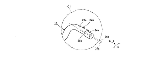
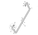
図1及び図2に示されるコネクタ装置に備えられる操作レバーを単体で示す斜視図である。It is a perspective view which shows the operation lever with which the connector apparatus shown by FIG.1 and FIG.2 is equipped alone.
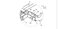
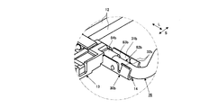
図3に示される円C1内を拡大してあらわす拡大斜視図である。FIG. 4 is an enlarged perspective view showing the inside of a circle C1 shown in FIG. 3 in an enlarged manner.
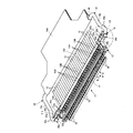
図1に示されるコネクタ装置についての導電性カバーが取り除かれた状態を示す斜視図である。It is a perspective view which shows the state from which the electroconductive cover about the connector apparatus shown by FIG. 1 was removed.
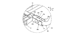
図5に示される円C2内を拡大してあらわす拡大斜視図である。FIG. 6 is an enlarged perspective view showing the inside of a circle C2 shown in FIG. 5 in an enlarged manner.
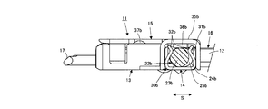
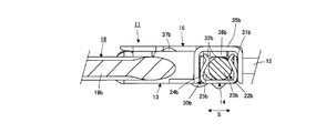
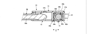
図1におけるA-A線に沿う断面を示す断面図である。FIG. 2 is a cross-sectional view showing a cross section taken along line AA in FIG. 1.
図2におけるB-B線に沿う断面を示す断面図である。FIG. 3 is a cross-sectional view showing a cross section taken along line BB in FIG. 2.
本発明に係るコネクタ装置の一例が嵌合する相手側コネクタ装置の一例を成す基板側コネクタ装置を示す斜視図である。It is a perspective view which shows the board | substrate side connector apparatus which comprises an example of the other party connector apparatus with which an example of the connector apparatus which concerns on this invention fits.
本発明に係るコネクタ装置の一例が嵌合する相手側コネクタ装置の一例を成す基板側コネクタ装置を示す正面図である。It is a front view which shows the board | substrate side connector apparatus which comprises an example of the other party connector apparatus with which an example of the connector apparatus which concerns on this invention fits.
図1に示されるコネクタ装置が図9及び図10に示される基板側コネクタ装置に嵌合した状態を示す斜視図である。It is a perspective view which shows the state which the connector apparatus shown by FIG. 1 fitted to the board | substrate side connector apparatus shown by FIG.9 and FIG.10.
図1に示されるコネクタ装置が図9及び図10に示される基板側コネクタ装置に嵌合した状態を示す斜視図である。It is a perspective view which shows the state which the connector apparatus shown by FIG. 1 fitted to the board | substrate side connector apparatus shown by FIG.9 and FIG.10.
本発明に係るコネクタ装置の他の例に備えられる操作レバーを単体で示す斜視図である。It is a perspective view which shows the operation lever with which the other example of the connector apparatus which concerns on this invention is equipped alone.
図13に示される円C3内を拡大してあらわす拡大斜視図である。It is an expansion perspective view which expands and shows the inside of the circle C3 shown by FIG.
本発明に係るコネクタ装置の他の例の一部を拡大してあらわす拡大斜視図である。It is an expansion perspective view which expands and shows a part of other example of the connector device concerning the present invention.
本発明に係るコネクタ装置の他の例における一断面を示す断面図である。It is sectional drawing which shows one cross section in the other example of the connector apparatus which concerns on this invention.
本発明に係るコネクタ装置の他の例における一断面を示す断面図である。It is sectional drawing which shows one cross section in the other example of the connector apparatus which concerns on this invention.
本発明に係るコネクタ装置のさらに他の例に備えられる操作レバーを単体で示す斜視図である。It is a perspective view which shows the operation lever with which the further another example of the connector apparatus which concerns on this invention is provided alone.
図18に示される円C4内を拡大してあらわす拡大斜視図である。It is an expansion perspective view which expands and shows the inside of the circle C4 shown by FIG.
本発明に係るコネクタ装置のさらに他の例の一部を拡大してあらわす拡大斜視図である。It is an expansion perspective view which expands and shows a part of other example of the connector device concerning the present invention.
本発明に係るコネクタ装置のさらに他の例における一断面を示す断面図である。It is sectional drawing which shows one cross section in the further another example of the connector apparatus which concerns on this invention.
本発明に係るコネクタ装置のさらに他の例における一断面を示す断面図である。It is sectional drawing which shows one cross section in the further another example of the connector apparatus which concerns on this invention.
符号の説明Explanation of symbols
11・・・コネクタ装置, 12・・・同軸ケーブル, 13,41・・・絶縁ハウジング, 14,42・・・導電性シェル, 15・・・導電性カバー, 16,56,76・・・操作レバー, 16A・・・操作タグ, 17・・・嵌合凸部, 18,44・・・導電コンタクト, 19a,19b,59A,59B,79a,79b・・・屈曲腕部, 20,60,80・・・連結部, 21,61,81・・・(操作レバー16,56もしくは76の)本体部, 22a,22b,62a,62b,82a,82b・・・(操作レバー16,56もしくは76の)端部, 23a,23b,63a,63b,83a,83b・・・伸長部分, 24a,24b,64a,64b,84a,84b・・・先端部分, 25a,25b・・・段部, 30a,30b・・・支持機構, 31a,31b・・・保持部, 32a,32b・・・係止部, 35a,35b・・・(導電性カバー15の)端部, 36a,36b・・・抑え片部, 37a,37b・・・係合突起, 40・・・基板側コネクタ装置(相手側コネクタ装置), 43・・・嵌合凹部, 46a,46b・・・係合孔, 47a,47b・・・接地接続端子, 48a,48b・・・弾性係合部
DESCRIPTION OF SYMBOLS 11 ... Connector apparatus, 12 ... Coaxial cable, 13, 41 ... Insulation housing, 14, 42 ... Conductive shell, 15 ... Conductive cover, 16, 56, 76 ... Operation Lever, 16A ... operation tag, 17 ... fitting projection, 18, 44 ... conductive contact, 19a, 19b, 59A, 59B, 79a, 79b ... bent arm, 20, 60, 80 ... Connecting part, rod 21, 61, 81 ... (main part of operating lever 16, 56 or 76), 22a, 22b, 62a, 62b, 82a, 82b ... (operating lever 16, 56 or 76 ) End part, 23a, 23b, 63a, 63b, 83a, 83b ... extension part, 24a, 24b, 64a, 64b, 84a, 84b ... tip part, 25a, 25 ... Step part, 30a, 30b ... Support mechanism, 31a, 31b ... Holding part, 32a, 32b ... Locking part, 35a, 35b ... (End of conductive cover 15), 36a, 36b ... holding piece, 37a, 37b ... engagement protrusion, 40 ... board side connector device (mating side connector device), 43 ... fitting recess, 46a, 46b ... engagement Joint hole, 47a, 47b ... ground connection terminal, 48a, 48b ... elastic engagement part
本発明を実施するための最良の形態は、以下に述べられる本発明についての実施例をもって説明される。
The best mode for carrying out the present invention will be described with reference to the following embodiments of the present invention.
図1及び図2は、本発明に係るコネクタ装置の一例(実施例1)を、それに連結された複数のケーブルと共に示す。
1 and 2 show an example (Example 1) of a connector device according to the present invention together with a plurality of cables connected thereto.
図1及び図2において、実施例1を成すコネクタ装置11は、例えば、複数の同軸ケーブル12が電気的に連結されたもとで、例えば、ソリッド印刷配線基板とされる基板にそれに設けられた電気回路構成部との電気的接続がなされて取り付けられた、基板側コネクタ装置とされる相手側コネクタ装置に嵌合する、ケーブル等側コネクタ装置として用いられるものとされている。そして、コネクタ装置11は、合成樹脂等の絶縁材料によって形成された絶縁ハウジング13, 外部からの電磁波ノイズ対策のため絶縁ハウジング13の外面部を部分的に覆うものとされた、例えば、各々が弾性を有した金属板材料が屈曲されて成る導電性シェル14及び導電性カバー15、及び、金属棒状部材が屈曲されて形成され、絶縁ハウジング13に対して回動可能に配された操作レバー16を備えている。
1 and 2, the connector device 11 according to the first embodiment includes, for example, an electric circuit provided on a substrate to be a solid printed wiring board, for example, with a plurality of coaxial cables 12 electrically connected thereto. It is supposed to be used as a cable or the like side connector device that fits into a mating side connector device that is a board side connector device that is attached by electrical connection with a component. And the connector apparatus 11 shall cover the outer surface part of the insulation housing 13 and the insulation housing 13 formed with insulation materials, such as a synthetic resin, and the outer surface part of the insulation housing 13 for the countermeasure against electromagnetic wave noise from the exterior, for example, each is elastic A conductive shell 14 and a conductive cover 15 formed by bending a metal plate material having a metal plate material, and an operation lever 16 formed by bending a metal bar-like member and arranged to be rotatable with respect to the insulating housing 13. I have.
絶縁ハウジング13には、相手側コネクタ装置(基板側コネクタ装置)に設けられた嵌合凹部との嵌合状態におかれる、絶縁ハウジング13の長手方向(矢印Lにより示される方向であって、以下、L方向という。)に伸びる嵌合凸部17が設けられている。また、絶縁ハウジング13には、各々が、例えば、弾性を有した金属材料が屈曲されて形成された複数の導電コンタクト18が、夫々の一部分が嵌合凸部17にL方向に沿って配列配置されるものとされて配されている。
The insulating housing 13 has a longitudinal direction (a direction indicated by an arrow L), which is in a fitting state with a fitting recess provided in the mating connector device (board-side connector device), and is described below. , Referred to as the L direction). The insulating housing 13 includes a plurality of conductive contacts 18 formed by bending a metal material having elasticity, for example, and a part of each of the conductive contacts 18 is arranged in the L-direction on the fitting protrusions 17. It is supposed to be arranged.
複数の導電コンタクト18の夫々における嵌合凸部17に配置された部分は、嵌合凸部17が相手側コネクタ装置に設けられた嵌合凹部との嵌合状態におかれるとき、その相手側コネクタ装置に配されて基板との電気的接続がなされた複数の導電コンタクトのうちの対応するものに接触接続され、それにより、複数の導電コンタクト18が相手側コネクタ装置における複数の導電コンタクトに夫々接続されることになる。また、複数の導電コンタクト18の夫々には、複数の同軸ケーブル12のうちの対応するものの信号導体が接続される。複数の同軸ケーブル12の夫々は、その信号導体が導電コンタクト18に接続されるとともに、その接地導体が導電性シェル14及び導電性カバー15に接触接続されて、コネクタ装置11に電気的に連結される。
A portion of each of the plurality of conductive contacts 18 arranged on the fitting convex portion 17 is arranged such that when the fitting convex portion 17 is in a fitting state with a fitting concave portion provided in the counterpart connector device, A plurality of conductive contacts disposed in the connector device and electrically connected to the substrate are contact-connected to each other, whereby the plurality of conductive contacts 18 are respectively connected to the plurality of conductive contacts in the mating connector device. Will be connected. In addition, a signal conductor of a corresponding one of the plurality of coaxial cables 12 is connected to each of the plurality of conductive contacts 18. Each of the plurality of coaxial cables 12 has a signal conductor connected to the conductive contact 18 and a ground conductor connected to the conductive shell 14 and the conductive cover 15 to be electrically connected to the connector device 11. The
操作レバー16は、図3に単体で示されるように、一対の屈曲腕部19a及び19bがL方向に沿って伸びる連結部20によって連結されて成るものとされる本体部21と、本体部21の両端に夫々連結された一対の端部22a及び22bと、を有している。端部22aは、本体部21の一端を形成する屈曲腕部19aに連結されており、屈曲腕部19aに屈曲して連なる伸長部分23aと伸長部分23aに更に連なる先端部分24aとを有していて、L方向に沿う方向に伸びるものとされている。同様に、端部22bは、本体部21の他端を形成する屈曲腕部19bに連結されており、屈曲腕部19bに屈曲して連なる伸長部分23bと伸長部分23bに更に連なる先端部分24bとを有していて、L方向に沿う方向に伸びるものとされている。
As shown in FIG. 3, the operation lever 16 includes a main body portion 21 formed by connecting a pair of bent arm portions 19 a and 19 b by a connecting portion 20 extending in the L direction, and a main body portion 21. And a pair of end portions 22a and 22b respectively connected to both ends. The end portion 22a is connected to a bent arm portion 19a that forms one end of the main body portion 21, and has an extended portion 23a that is bent and connected to the bent arm portion 19a, and a tip portion 24a that is further connected to the extended portion 23a. And extending in the direction along the L direction. Similarly, the end portion 22b is connected to a bent arm portion 19b that forms the other end of the main body portion 21, and an extended portion 23b that bends and continues to the bent arm portion 19b, and a distal end portion 24b that further continues to the extended portion 23b. And extends in the direction along the L direction.
図3に示される操作レバー16の端部22aを囲む円C1内を拡大してあらわす図4に示されるように、操作レバー16の端部22aが有する伸長部分23aと先端部分24aとは、先端部分24aが伸長部分23aに対して伸長部分23aの中心軸方向に直交する方向に平行変位したものとされて伸長部分23aとの境界に段部25aを形成するものとされている。従って、先端部分24aの中心軸方向は伸長部分23aの中心軸方向と平行なものとなり、伸長部分23aの中心軸方向はL方向に沿う方向となるので、先端部分24aの中心軸方向もL方向に沿う方向となる。そして、図4に示されるように、伸長部分23aと先端部分24aとは、L方向に沿って伸びる伸長部分23aの仮想中心軸線26aに対して、同じくL方向に沿って伸びる先端部分24aの仮想中心軸線27aが、L方向に直交する方向(矢印Sにより示される方向であって、以下、S方向という。)に平行変位したものとなる関係におかれる。
As shown in FIG. 4 which is an enlarged view of the circle C1 surrounding the end portion 22a of the operation lever 16 shown in FIG. 3, the extended portion 23a and the front end portion 24a of the end portion 22a of the operation lever 16 are The portion 24a is parallel-displaced in the direction perpendicular to the central axis direction of the extended portion 23a with respect to the extended portion 23a, and a step portion 25a is formed at the boundary with the extended portion 23a. Accordingly, the central axis direction of the distal end portion 24a is parallel to the central axial direction of the elongated portion 23a, and the central axial direction of the elongated portion 23a is along the L direction. It becomes the direction along. And as FIG. 4 shows, the extension part 23a and the front-end | tip part 24a are the virtual of the front-end | tip part 24a similarly extended along the L direction with respect to the virtual center axis line 26a of the extension part 23a extended along the L direction. The central axis line 27a is placed in a relationship of parallel displacement in a direction orthogonal to the L direction (the direction indicated by the arrow S, hereinafter referred to as the S direction).
同様に、操作レバー16の端部22bが有する伸長部分23bと先端部分24bとは、先端部分24bが伸長部分23bに対して伸長部分23bの中心軸方向に直交する方向に平行変位したものとされて伸長部分23bとの境界に段部25bを形成するものとされている。従って、先端部分24bの中心軸方向は伸長部分23bの中心軸方向と平行なものとなり、伸長部分23bの中心軸方向はL方向に沿う方向となるので、先端部分24bの中心軸方向もL方向に沿う方向となる。そして、伸長部分23bと先端部分24bとは、図示は省略されているが、L方向に沿って伸びる伸長部分23bの仮想中心軸線に対して、同じくL方向に沿って伸びる先端部分24bの仮想中心軸線が、L方向に直交するS方向に平行変位したものとなる関係におかれる。
Similarly, the extended portion 23b and the distal end portion 24b of the end portion 22b of the operation lever 16 are such that the distal end portion 24b is displaced in parallel with the extended portion 23b in a direction orthogonal to the central axis direction of the extended portion 23b. Thus, a step portion 25b is formed at the boundary with the elongated portion 23b. Accordingly, the central axis direction of the distal end portion 24b is parallel to the central axial direction of the elongated portion 23b, and the central axial direction of the elongated portion 23b is along the L direction. It becomes the direction along. The extension portion 23b and the tip portion 24b are not shown, but the virtual center of the tip portion 24b extending along the L direction is also the same as the virtual center axis of the extension portion 23b extending along the L direction. The axis line is in a relationship of parallel displacement in the S direction orthogonal to the L direction.
このように構成される操作レバー16にあっては、図1及び図2に示されるように、その一対の端部22a及び22b、即ち、上述のように伸長部分23aと先端部分24aとを有した端部22a及び伸長部分23bと先端部分24bとを有した端部22bが、導電性シェル14におけるL方向の両端部によって夫々回動可能に支持されている。斯かる端部22a及び22bは、夫々がL方向に沿う方向において絶縁ハウジング13の端部から中央部に向かう向きをもって伸びて、各々の先端部分24a及び24bを相互対向させている。それにより、操作レバー16は、絶縁ハウジング13に対して回動可能とされている。また、操作レバー16の本体部21を形成する連結部20には、操作レバー16についての回動操作を容易にするための操作タグ16Aが取り付けられている。
As shown in FIGS. 1 and 2, the operation lever 16 configured as described above has a pair of end portions 22a and 22b, that is, an extension portion 23a and a tip portion 24a as described above. The end portion 22b having the end portion 22a and the extending portion 23b and the tip end portion 24b are rotatably supported by both end portions of the conductive shell 14 in the L direction. The end portions 22a and 22b extend in a direction from the end portion of the insulating housing 13 toward the center portion in the direction along the L direction, and the tip portions 24a and 24b are opposed to each other. Thereby, the operation lever 16 is rotatable with respect to the insulating housing 13. Further, an operation tag 16 </ b> A for facilitating the rotation operation of the operation lever 16 is attached to the connecting portion 20 that forms the main body portion 21 of the operation lever 16.
導電性シェル14は、絶縁ハウジング13における図1及び図2の夫々において下側となる外面(以下、底面という)を部分的に覆うものとされ、また、導電性カバー15は、絶縁ハウジング13における図1及び図2のに夫々において上側となる外面(以下、上面という)を部分的に覆うものとされる。そして、コネクタ装置11についての、複数の同軸ケーブル12が連結されたもとで導電性カバー15が取り除かれた状態を示す図5に示されるように、導電性シェル14におけるL方向の両端部には、操作レバー16の一対の端部22a及び22b、即ち、伸長部分23aと先端部分24aとを有した端部22a及び伸長部分23bと先端部分24bとを有した端部22bを、夫々回動可能に支持する一対の支持機構30a及び30bが設けられている。
The conductive shell 14 partially covers the lower outer surface (hereinafter referred to as the bottom surface) of the insulating housing 13 in FIGS. 1 and 2, and the conductive cover 15 is provided in the insulating housing 13. In FIG. 1 and FIG. 2, the outer surface (hereinafter referred to as the upper surface) on the upper side is partially covered. And as shown in FIG. 5 which shows the state in which the conductive cover 15 was removed with the plurality of coaxial cables 12 connected to the connector device 11, both ends in the L direction of the conductive shell 14 are A pair of end portions 22a and 22b of the operating lever 16, that is, an end portion 22a having an extension portion 23a and a tip portion 24a and an end portion 22b having an extension portion 23b and a tip portion 24b are rotatable. A pair of support mechanisms 30a and 30b to support is provided.
なお、図5に示されるように、複数の同軸ケーブル12の夫々は、その信号導体12Aが、導電コンタクト18に接続されるとともに、その接地導体12Bが接地用共通導体13Xに接続される。接地用共通導体13Xは導電性シェル14及び導電性カバー15に接触接続される。
As shown in FIG. 5, in each of the plurality of coaxial cables 12, the signal conductor 12A is connected to the conductive contact 18, and the ground conductor 12B is connected to the ground common conductor 13X. The grounding common conductor 13 </ b> X is contact-connected to the conductive shell 14 and the conductive cover 15.
支持機構30aは、操作レバー16の伸長部分23aと先端部分24aとを有した端部22aを保持する、弾性を有した保持部31aを備えており、また、支持機構30bは、操作レバー16の伸長部分23bと先端部分24bとを有した端部22bを保持する、弾性を有した保持部31bを備えている。操作レバー16の一対の端部22a及び22bの夫々は、L方向に沿う方向において絶縁ハウジング13の端部から中央部に向かう向きをもって伸びているので、これらの端部22a及び22bを支持する支持機構30a及び30bに夫々備えられた保持部31a及び31bの夫々もL方向に伸びるものとされている。そして、操作レバー16は、保持部31a及び31bにより夫々保持された端部22a及び22bを回動中心として、絶縁ハウジング13に対して回動せしめられ、図1に示されるような、本体部21が、コネクタ装置11に電気的に連結された複数の同軸ケーブル12側に配されることになる位置と、図2に示されるような、本体部21が、絶縁ハウジング13に設けられた嵌合凸部17側に配されることになる位置とを、選択的にとるものとされる。
The support mechanism 30 a includes an elastic holding portion 31 a that holds an end portion 22 a having an extended portion 23 a and a tip end portion 24 a of the operation lever 16, and the support mechanism 30 b includes the operation lever 16. An elastic holding portion 31b is provided to hold the end portion 22b having the extended portion 23b and the tip portion 24b. Each of the pair of end portions 22a and 22b of the operation lever 16 extends in a direction along the L direction from the end portion of the insulating housing 13 toward the center portion, and thus supports the end portions 22a and 22b. Each of the holding portions 31a and 31b provided in the mechanisms 30a and 30b also extends in the L direction. The operation lever 16 is rotated with respect to the insulating housing 13 around the end portions 22a and 22b held by the holding portions 31a and 31b, respectively, and the main body portion 21 as shown in FIG. Is located on the side of the plurality of coaxial cables 12 that are electrically connected to the connector device 11, and the body portion 21 as shown in FIG. The position to be arranged on the convex portion 17 side is selectively taken.
さらに、支持機構30aには、操作レバー16の伸長部分23aと先端部分24aとを有した端部22aにおける段部25aに係合して端部22aを係止する状態をとる係止部32aが備えられており、また、支持機構30bには、操作レバー16の伸長部分23bと先端部分24bとを有した端部22bにおける段部25bに係合して端部22bを係止する状態をとる係止部32bが備えられている。
Further, the support mechanism 30a includes a locking portion 32a that engages with the step portion 25a of the end portion 22a having the extended portion 23a and the distal end portion 24a of the operation lever 16 to lock the end portion 22a. In addition, the support mechanism 30b is engaged with the step portion 25b of the end portion 22b having the extended portion 23b and the distal end portion 24b of the operation lever 16 to lock the end portion 22b. A locking portion 32b is provided.
図5に示される操作レバー16の端部22b及び導電性シェル14の一端部に設けられた支持機構30bを含む部分を囲む円C2内を拡大してあらわす図6に示されるように、支持機構30bに備えられた保持部31bは、L方向に伸びて操作レバー16の端部22bにおける伸長部分23b,先端部分24b及び段部25bを含む部分が回動可能に配される溝状部を形成しており、また、支持機構30bに備えられた係止部32bは、S方向において操作レバー16の端部22bにおける伸長部分23bを挟んで相互対向する一対の屈曲壁状部を形成している。支持機構30bに備えられた保持部31bが形成する溝状部は、それに配された端部22bにおける伸長部分23b,先端部分24b及び段部25bを含む部分について、S方向における位置規制を行う。また、支持機構30bに備えられた係止部32bが形成する屈曲壁状部は、そのL方向における保持部31b側の端面が、端部22bにおける段部25bに係合する状態をとる。
As shown in FIG. 6 which expands and shows the inside of the circle C2 surrounding the part including the support mechanism 30b provided at the end 22b of the operation lever 16 and the one end of the conductive shell 14 shown in FIG. The holding portion 31b provided in 30b extends in the L direction to form a groove-like portion in which the extended portion 23b, the tip portion 24b, and the step portion 25b of the end portion 22b of the operation lever 16 are rotatably arranged. Further, the locking portion 32b provided in the support mechanism 30b forms a pair of bent wall-like portions that face each other across the extended portion 23b of the end portion 22b of the operation lever 16 in the S direction. . The groove-shaped portion formed by the holding portion 31b provided in the support mechanism 30b regulates the position in the S direction with respect to the portion including the extended portion 23b, the tip portion 24b, and the step portion 25b in the end portion 22b disposed thereon. Further, the bent wall-shaped portion formed by the locking portion 32b provided in the support mechanism 30b is in a state in which the end surface on the holding portion 31b side in the L direction is engaged with the step portion 25b in the end portion 22b.
同様に、支持機構30aに備えられた保持部31aは、L方向に伸びて操作レバー16の端部22aにおける伸長部分23a,先端部分24a及び段部25aを含む部分が回動可能に配される溝状部を形成しており、また、支持機構30aに備えられた係止部32aは、S方向において操作レバー16の端部22aにおける伸長部分23aを挟んで相互対向する一対の屈曲壁状部を形成している。支持機構30aに備えられた保持部31aが形成する溝状部は、それに配された端部22aにおける伸長部分23a,先端部分24a及び段部25aを含む部分について、S方向における位置規制を行う。また、支持機構30aに備えられた係止部32aが形成する屈曲壁状部は、そのL方向における保持部31a側の端面が、端部22aにおける段部25aに係合する状態をとる。
Similarly, the holding portion 31a provided in the support mechanism 30a extends in the L direction, and a portion including the extended portion 23a, the tip portion 24a, and the step portion 25a in the end portion 22a of the operation lever 16 is rotatably disposed. The locking portion 32a provided in the support mechanism 30a forms a groove-like portion, and a pair of bent wall-like portions facing each other across the extended portion 23a of the end portion 22a of the operation lever 16 in the S direction. Is forming. The groove-shaped portion formed by the holding portion 31a provided in the support mechanism 30a regulates the position in the S direction with respect to the portion including the extended portion 23a, the tip portion 24a, and the step portion 25a in the end portion 22a disposed thereon. Further, the bent wall-shaped portion formed by the locking portion 32a provided in the support mechanism 30a is in a state where the end surface on the holding portion 31a side in the L direction is engaged with the step portion 25a in the end portion 22a.
導電性カバー15は、図1及び図2に示されるように絶縁ハウジング13における上面を部分的に覆うものとされるとき、そのL方向の両端部35a及び35bが、導電性シェル14におけるL方向の両端部に設けられて、操作レバー16の一対の端部22a及び22bを夫々回動可能に支持する支持機構30a及び30bを、夫々覆うものとされる。そして、導電性カバー15におけるL方向の両端部35a及び35bには、抑え片部36a及び36bが夫々設けられていて、これらの抑え片部36a及び36bは、両端部35a及び35bが支持機構30a及び30bを夫々覆うとき、支持機構30a及び30bにより支持された操作レバー16の端部22a及び22bに夫々当接し、それらを抑える役割を果たす。このようにして、導電性カバー15の両端部35a及び35bが支持機構30a及び30bを夫々覆うことにより、支持機構30aが備える保持部31a及び係止部32aの夫々の内部、及び、支持機構30bが備える保持部31b及び係止部32bの夫々の内部への塵埃や異物の侵入が防止される。
When the conductive cover 15 partially covers the upper surface of the insulating housing 13 as shown in FIGS. 1 and 2, both end portions 35 a and 35 b in the L direction are in the L direction in the conductive shell 14. The support mechanisms 30a and 30b, which are provided at both ends of the control lever 16 and rotatably support the pair of end portions 22a and 22b of the operation lever 16, respectively. Further, holding piece portions 36a and 36b are respectively provided at both ends 35a and 35b in the L direction of the conductive cover 15, and these holding pieces 36a and 36b have both ends 35a and 35b supported by the support mechanism 30a. And 30b respectively contact the end portions 22a and 22b of the operation lever 16 supported by the support mechanisms 30a and 30b, respectively, and serve to suppress them. In this manner, both end portions 35a and 35b of the conductive cover 15 cover the support mechanisms 30a and 30b, respectively, and thereby the inside of each of the holding portion 31a and the locking portion 32a included in the support mechanism 30a and the support mechanism 30b. Dust and foreign matter are prevented from entering the holding portion 31b and the locking portion 32b.
また、導電性カバー15には、その両端部35a及び35bの近傍に、絶縁ハウジング13の嵌合凸部17が相手側コネクタ装置に設けられた嵌合凹部との嵌合状態におかれるとき、相手側コネクタ装置の導電性シェルに設けられた係合孔に係合する係合突起37a及び37bが設けられている。係合突起37a及び37bの夫々は、導電性カバー15の一部が形成する弾性片に形成されていて、相手側コネクタ装置の導電性シェルに設けられた係合孔との係合及びその係合孔からの離脱を、弾性片の弾性変形を伴って行う。
Further, when the conductive cover 15 is in a state of being fitted with the fitting concave portion provided in the mating connector device in the vicinity of both end portions 35a and 35b thereof, the fitting convex portion 17 of the insulating housing 13 Engagement protrusions 37a and 37b that engage with engagement holes provided in the conductive shell of the mating connector device are provided. Each of the engagement protrusions 37a and 37b is formed on an elastic piece formed by a part of the conductive cover 15, and engages with and engages with an engagement hole provided in the conductive shell of the mating connector device. The separation from the joint hole is performed with the elastic deformation of the elastic piece.
このようなもとで、導電性シェル14の端部に設けられた支持機構30aに備えられた弾性を有した保持部31aが、それが形成する溝状部に配された操作レバー16の端部22aを形成する伸長部分23a及び先端部分24aを、先端部分24aの伸長部分23aに対する平行変位方向を操作レバー16の回動操作に応じて変化させることを許す状態をもって保持する。同様に、導電性シェル14の端部に設けられた支持機構30bに備えられた弾性を有した保持部31bが、それが形成する溝状部に配された操作レバー16の端部22bを形成する伸長部分23b及び先端部分24bを、先端部分24bの伸長部分23bに対する平行変位方向を操作レバー16の回動操作に応じて変化させることを許す状態をもって保持する。
Under such circumstances, the holding portion 31a having elasticity provided in the support mechanism 30a provided at the end portion of the conductive shell 14 is connected to the end of the operation lever 16 disposed in the groove portion formed by the holding portion 31a. The extended portion 23a and the distal end portion 24a forming the portion 22a are held in a state that allows the parallel displacement direction of the distal end portion 24a to the extended portion 23a to be changed according to the turning operation of the operation lever 16. Similarly, the holding portion 31b having elasticity provided in the support mechanism 30b provided at the end portion of the conductive shell 14 forms the end portion 22b of the operation lever 16 arranged in the groove-like portion formed by the holding portion 31b. The extending portion 23b and the distal end portion 24b to be held are held in a state that allows the parallel displacement direction of the distal end portion 24b to the elongated portion 23b to be changed according to the turning operation of the operation lever 16.
そして、図1に示されるように、操作レバー16が、絶縁ハウジング13に対して回動せしめられて、本体部21がコネクタ装置11に電気的に連結された複数の同軸ケーブル12側に配されることになる位置をとるものとされるときには、図1に示されるA-A線に沿う断面をあらわす図7に示されるように、導電性シェル14の端部に設けられた支持機構30bにおいて、保持部31bにより保持された操作レバー16の端部22bを形成する伸長部分23b及び先端部分24bが、保持部31bが形成する溝状部内において、先端部分24bが、伸長部分23bに対し、S方向において複数の同軸ケーブル12側に平行変位した状態におかれる。それにより、保持部31bが形成する溝状部内で、伸長部分23bがS方向において絶縁ハウジング13に設けられた嵌合凸部17側に配されるとともに、先端部分24bがS方向において複数の同軸ケーブル12側に配されることになる。
As shown in FIG. 1, the operation lever 16 is rotated with respect to the insulating housing 13, and the main body portion 21 is arranged on the side of the plurality of coaxial cables 12 electrically connected to the connector device 11. In the support mechanism 30b provided at the end of the conductive shell 14, as shown in FIG. 7 showing a cross section along the line AA shown in FIG. The extension portion 23b and the tip portion 24b forming the end portion 22b of the operation lever 16 held by the holding portion 31b are within the groove-like portion formed by the holding portion 31b. It is put in a state of being displaced parallel to the plurality of coaxial cables 12 in the direction. Accordingly, in the groove-shaped portion formed by the holding portion 31b, the extended portion 23b is arranged on the fitting convex portion 17 side provided in the insulating housing 13 in the S direction, and the tip portion 24b has a plurality of coaxial portions in the S direction. It will be arranged on the cable 12 side.
このようなもとで、操作レバー16に、それにおける端部22bをL方向において絶縁ハウジング13の中央部から端部に向かう方向への変位、即ち、絶縁ハウジング13の外方への変位を生じさせる外力が加えられ、端部22bが絶縁ハウジング13の中央部から端部に向かう方向に変位せしめられるときには、支持機構30bに備えられた係止部32bが、そのL方向における保持部31b側の端面をもって、端部22bにおける先端部分24bにより形成される段部25bに係合して、段部25bを係止する。それにより、操作レバー16における端部22bの支持機構30bからの抜脱が確実に阻止される。
Under such circumstances, the end portion 22b of the operation lever 16 is displaced in the L direction in the direction from the center portion of the insulating housing 13 toward the end portion, that is, the outer side of the insulating housing 13 is displaced. When the external force to be applied is applied and the end portion 22b is displaced in the direction from the central portion of the insulating housing 13 toward the end portion, the locking portion 32b provided in the support mechanism 30b is moved to the holding portion 31b side in the L direction. With the end face, the step portion 25b is engaged by engaging with a step portion 25b formed by the tip portion 24b of the end portion 22b. This reliably prevents the end 22b of the operation lever 16 from being removed from the support mechanism 30b.
このとき、導電性シェル14の端部に設けられた支持機構30aにおいて、保持部31aにより保持された操作レバー16の端部22aを形成する伸長部分23a及び先端部分24aも、保持部31aが形成する溝状部内において、先端部分24aが、伸長部分23aに対し、S方向において複数の同軸ケーブル12側に平行変位した状態におかれる。それにより、保持部31aが形成する溝状部内で、伸長部分23aがS方向において絶縁ハウジング13に設けられた嵌合凸部17側に配されるとともに、先端部分24aがS方向において複数の同軸ケーブル12側に配されることになる。
At this time, in the support mechanism 30a provided at the end portion of the conductive shell 14, the holding portion 31a also forms the extended portion 23a and the tip portion 24a that form the end portion 22a of the operation lever 16 held by the holding portion 31a. In the groove-shaped portion, the distal end portion 24a is placed in a state of being displaced parallel to the plurality of coaxial cables 12 in the S direction with respect to the elongated portion 23a. Accordingly, in the groove-shaped portion formed by the holding portion 31a, the extended portion 23a is arranged on the fitting convex portion 17 side provided in the insulating housing 13 in the S direction, and the tip portion 24a has a plurality of coaxial portions in the S direction. It will be arranged on the cable 12 side.
このようなもとで、操作レバー16に、それにおける端部22aをL方向において絶縁ハウジング13の中央部から端部に向かう方向への変位、即ち、絶縁ハウジング13の外方への変位を生じさせる外力が加えられ、端部22aが絶縁ハウジング13の中央部から端部に向かう方向に変位せしめられるときには、支持機構30aに備えられた係止部32aが、そのL方向における保持部31a側の端面をもって、端部22aにおける先端部分24aにより形成される段部25aに係合して、段部25aを係止する。それにより、操作レバー16における端部22aの支持機構30aからの抜脱が確実に阻止される。
Under such circumstances, the end portion 22a of the operation lever 16 is displaced in the L direction in the direction from the center portion to the end portion of the insulating housing 13, that is, the outer direction of the insulating housing 13 is displaced. When the external force to be applied is applied and the end portion 22a is displaced in the direction from the central portion of the insulating housing 13 toward the end portion, the locking portion 32a provided in the support mechanism 30a is moved to the holding portion 31a side in the L direction. With the end face, the step portion 25a is engaged by engaging with the step portion 25a formed by the tip portion 24a of the end portion 22a. This reliably prevents the end 22a of the operation lever 16 from being detached from the support mechanism 30a.
また、図2に示されるように、操作レバー16が、絶縁ハウジング13に対して回動せしめられて、本体部21が絶縁ハウジング13に設けられた嵌合凸部17側に配されることになる位置をとるものとされるときには、図2に示されるB-B線に沿う断面をあらわす図8に示されるように、導電性シェル14の端部に設けられた支持機構30bにおいて、保持部31bにより保持された操作レバー16の端部22bを形成する伸長部分23b及び先端部分24bが、保持部31bが形成する溝状部内において、先端部分24bが、伸長部分23bに対し、S方向において絶縁ハウジング13に設けられた嵌合凸部17側(複数の同軸ケーブル12側とは反対側)に平行変位した状態におかれる。それにより、保持部31bが形成する溝状部内で、伸長部分23bがS方向において複数の同軸ケーブル12側に配されるとともに、先端部分24bがS方向において絶縁ハウジング13に設けられた嵌合凸部17側に配されることになる。
In addition, as shown in FIG. 2, the operation lever 16 is rotated with respect to the insulating housing 13, and the main body portion 21 is arranged on the fitting convex portion 17 side provided in the insulating housing 13. In the supporting mechanism 30b provided at the end of the conductive shell 14, as shown in FIG. 8 showing a cross section along the line BB shown in FIG. The extended portion 23b and the distal end portion 24b forming the end portion 22b of the operation lever 16 held by 31b are insulated in the S direction from the extended portion 23b in the groove portion formed by the holding portion 31b. It is placed in a state where it is displaced parallel to the fitting convex portion 17 side (the side opposite to the plurality of coaxial cables 12 side) provided in the housing 13. Thereby, in the groove-shaped portion formed by the holding portion 31b, the extended portion 23b is arranged on the side of the plurality of coaxial cables 12 in the S direction, and the front end portion 24b is a fitting protrusion provided on the insulating housing 13 in the S direction. It will be arranged on the part 17 side.
このようなもとで、操作レバー16に、それにおける端部22bをL方向において絶縁ハウジング13の中央部から端部に向かう方向への変位、即ち、絶縁ハウジング13の外方への変位を生じさせる外力が加えられ、端部22bが絶縁ハウジング13の中央部から端部に向かう方向に変位せしめられるときには、支持機構30bに備えられた係止部32bが、そのL方向における保持部31b側の端面をもって、端部22bにおける先端部分24bにより形成される段部25bに係合して、段部25bを係止する。それにより、操作レバー16における端部22bの支持機構30bからの抜脱が確実に阻止される。
Under such circumstances, the end portion 22b of the operation lever 16 is displaced in the L direction in the direction from the center portion of the insulating housing 13 toward the end portion, that is, the outer side of the insulating housing 13 is displaced. When the external force to be applied is applied and the end portion 22b is displaced in the direction from the central portion of the insulating housing 13 toward the end portion, the locking portion 32b provided in the support mechanism 30b is moved to the holding portion 31b side in the L direction. With the end face, the step portion 25b is engaged by engaging with a step portion 25b formed by the tip portion 24b of the end portion 22b. This reliably prevents the end 22b of the operation lever 16 from being removed from the support mechanism 30b.
このとき、導電性シェル14の端部に設けられた支持機構30aにおいて、保持部31aにより保持された操作レバー16の端部22aを形成する伸長部分23a及び先端部分24aも、保持部31aが形成する溝状部内において、先端部分24aが、伸長部分23aに対し、S方向において絶縁ハウジング13に設けられた嵌合凸部17側(複数の同軸ケーブル12側とは反対側)に平行変位した状態におかれる。それにより、保持部31aが形成する溝状部内で、伸長部分23aがS方向において複数の同軸ケーブル12側に配されるとともに、先端部分24aがS方向において絶縁ハウジング13に設けられた嵌合凸部17側に配されることになる。
At this time, in the support mechanism 30a provided at the end portion of the conductive shell 14, the holding portion 31a also forms the extended portion 23a and the tip portion 24a that form the end portion 22a of the operation lever 16 held by the holding portion 31a. In the groove-shaped portion, the distal end portion 24a is displaced in parallel with the extended portion 23a toward the fitting convex portion 17 side (the side opposite to the plurality of coaxial cables 12 side) provided in the insulating housing 13 in the S direction. Smelled. Thereby, in the groove-shaped portion formed by the holding portion 31a, the extended portion 23a is arranged on the side of the plurality of coaxial cables 12 in the S direction, and the front end portion 24a is provided on the insulating housing 13 in the S direction. It will be arranged on the part 17 side.
このようなもとで、操作レバー16に、それにおける端部22aをL方向において絶縁ハウジング13の中央部から端部に向かう方向への変位、即ち、絶縁ハウジング13の外方への変位を生じさせる外力が加えられ、端部22aが絶縁ハウジング13の中央部から端部に向かう方向に変位せしめられるときには、支持機構30aに備えられた係止部32aが、そのL方向における保持部31a側の端面をもって、端部22aにおける先端部分24aにより形成される段部25aに係合して、段部25aを係止する。それにより、操作レバー16における端部22aの支持機構30aからの抜脱が確実に阻止される。
Under such circumstances, the end portion 22a of the operation lever 16 is displaced in the L direction in the direction from the center portion to the end portion of the insulating housing 13, that is, the outer direction of the insulating housing 13 is displaced. When the external force to be applied is applied and the end portion 22a is displaced in the direction from the central portion of the insulating housing 13 toward the end portion, the locking portion 32a provided in the support mechanism 30a is moved to the holding portion 31a side in the L direction. With the end face, the step portion 25a is engaged by engaging with the step portion 25a formed by the tip portion 24a of the end portion 22a. This reliably prevents the end 22a of the operation lever 16 from being detached from the support mechanism 30a.
なお、操作レバー16が、図1に示されるような、本体部21がコネクタ装置11に電気的に連結された複数の同軸ケーブル12側に配されることになる位置と、図2に示されるような、本体部21が絶縁ハウジング13に設けられた嵌合凸部17側に配されることになる位置との間の回動位置をとるもとにあっても、操作レバー16に、それにおける端部22aもしくは端部22bをL方向において絶縁ハウジング13の中央部から端部に向かう方向への変位、即ち、絶縁ハウジング13の外方への変位を生じさせる外力が加えられ、端部22aもしくは端部22bが絶縁ハウジング13の中央部から端部に向かう方向に変位せしめられるときには、支持機構30aに備えられた係止部32aが、そのL方向における保持部31a側の端面をもって、端部22aにおける先端部分24aにより形成される段部25aに係合し、さらに、導電性カバー15におけるL方向の端部35aに設けられた抑え片部36aが段部25aに係合して、段部25aを係止するとともに、支持機構30bに備えられた係止部32bが、そのL方向における保持部31b側の端面をもって、端部22bにおける先端部分24bにより形成される段部25bに係合し、さらに、導電性カバー15におけるL方向の端部35bに設けられた抑え片部36bが段部25bに係合して、段部25bを係止する。それにより、操作レバー16における端部22aもしくは端部22bの支持機構30aもしくは支持機構30bからの抜脱が確実に阻止される。
The operation lever 16 is located at the position where the main body portion 21 is arranged on the side of the plurality of coaxial cables 12 electrically connected to the connector device 11 as shown in FIG. Even when the main body portion 21 takes a rotational position between the main body portion 21 and the position where the main body portion 21 is disposed on the fitting convex portion 17 side provided in the insulating housing 13, An external force is applied to the end 22a or the end 22b in the direction of L in the direction from the center of the insulating housing 13 toward the end, that is, to the outside of the insulating housing 13, and the end 22a is applied. Alternatively, when the end portion 22b is displaced in the direction from the central portion of the insulating housing 13 toward the end portion, the locking portion 32a provided in the support mechanism 30a is the end on the holding portion 31a side in the L direction. Then, the step portion 25a formed by the tip portion 24a in the end portion 22a is engaged, and the holding piece portion 36a provided at the end portion 35a in the L direction of the conductive cover 15 is engaged with the step portion 25a. Then, the locking portion 32b provided in the support mechanism 30b has the end surface on the holding portion 31b side in the L direction, and the step portion 25b formed by the tip portion 24b in the end portion 22b. Furthermore, the holding piece 36b provided at the end portion 35b in the L direction of the conductive cover 15 engages with the step portion 25b to lock the step portion 25b. This reliably prevents the end portion 22a or the end portion 22b of the operation lever 16 from being detached from the support mechanism 30a or the support mechanism 30b.
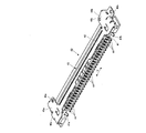
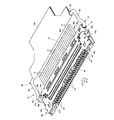
図9(斜視図)及び図10(正面図)は、コネクタ装置11が嵌合する相手側コネクタ装置の一例を成す基板側コネクタ装置40を示す。
FIG. 9 (perspective view) and FIG. 10 (front view) show a board-side connector device 40 that is an example of a mating connector device with which the connector device 11 is fitted.
図9及び図10において、基板側コネクタ装置40は、例えば、ソリッド印刷配線基板とされる基板にそれに設けられた電気回路構成部との電気的接続がなされて取り付けられた状態のもとで、コネクタ装置11が嵌合するものとされている。そして、基板側コネクタ装置40は、合成樹脂等の絶縁材料によって形成された絶縁ハウジング41、及び、外部からの電磁波ノイズ対策のため絶縁ハウジング41の外面部の殆どを覆うものとされた、例えば、弾性を有した金属板材料が屈曲されて成る導電性シェル42を備えている。
9 and 10, the board-side connector device 40 is, for example, in a state where the board-side connector device 40 is attached to a board to be a solid printed wiring board by being electrically connected to an electric circuit component provided on the board. The connector device 11 is to be fitted. The board-side connector device 40 is configured to cover most of the insulating housing 41 formed of an insulating material such as synthetic resin and the outer surface portion of the insulating housing 41 for countermeasures against electromagnetic noise from the outside. A conductive shell 42 formed by bending a metal plate material having elasticity is provided.
絶縁ハウジング41における図10における下方側の面からは、基板側コネクタ装置40が取り付けられる基板に設けられた透孔に嵌合する位置決め用の突起41a及び41bが突出している。
From the lower surface of the insulating housing 41 in FIG. 10, positioning protrusions 41 a and 41 b that fit into through holes provided in the board to which the board-side connector device 40 is attached protrude.
絶縁ハウジング41及び導電性シェル42には、コネクタ装置11に設けられた嵌合凸部17との嵌合状態におかれる、絶縁ハウジング41の長手方向(矢印L’により示される方向であって、以下、L’方向という。)に伸びる嵌合凹部43が設けられている。また、絶縁ハウジング41には、各々が、例えば、弾性を有した金属材料が屈曲されて形成された複数の導電コンタクト44が、L’方向に沿って配列配置されるものとされて配されている。そして、複数の導電コンタクト44の夫々における絶縁ハウジング41からその外方に突出する一端は、基板側コネクタ装置40が取り付けられる基板に設けられた配線パターン部に接続される接続端子を形成している。また、複数の導電コンタクト44の夫々における他端側の部分は、嵌合凹部43内に配され、コネクタ装置11の嵌合凸部17が嵌合凹部43との嵌合状態におかれるとき、コネクタ装置11に配された複数の導電コンタクト18のうちの対応するものが接触接続されるものとされる。
In the insulating housing 41 and the conductive shell 42, the longitudinal direction of the insulating housing 41 (in the direction indicated by the arrow L ′), which is in a fitted state with the fitting convex portion 17 provided in the connector device 11, Hereinafter, a fitting recess 43 extending in the L ′ direction) is provided. In addition, the insulating housing 41 is provided with a plurality of conductive contacts 44 formed by bending a metal material having elasticity, for example, arranged in the L ′ direction. Yes. One end of each of the plurality of conductive contacts 44 projecting outward from the insulating housing 41 forms a connection terminal connected to a wiring pattern portion provided on a substrate to which the board-side connector device 40 is attached. . Further, the other end portion of each of the plurality of conductive contacts 44 is disposed in the fitting recess 43, and when the fitting protrusion 17 of the connector device 11 is in a fitting state with the fitting recess 43, A corresponding one of the plurality of conductive contacts 18 arranged in the connector device 11 is contact-connected.
導電性シェル42には、L’方向における両端部45a及び45bに、コネクタ装置11の絶縁ハウジング13に設けられた嵌合凸部17が絶縁ハウジング41に設けられた嵌合凹部43との嵌合状態におかれるとき、コネクタ装置11の導電性カバー15に設けられた係合突起37a及び37bが夫々係合する係合孔46a及び46bが設けられている。
The conductive shell 42 is fitted to the fitting recesses 43 provided in the insulating housing 41 with the fitting protrusions 17 provided in the insulating housing 13 of the connector device 11 at both ends 45 a and 45 b in the L ′ direction. When placed in the state, engagement holes 46a and 46b are provided to engage with the engagement protrusions 37a and 37b provided on the conductive cover 15 of the connector device 11, respectively.
また、導電性シェル42には、配列配置された複数の導電コンタクト44を挟む位置において絶縁ハウジング41からその外部に突出し、基板側コネクタ装置40が取り付けられる基板に設けられた接地接続部に接続される接地接続端子47a及び47bが設けられている。
Further, the conductive shell 42 protrudes from the insulating housing 41 at a position sandwiching the plurality of conductive contacts 44 arranged in an array, and is connected to a ground connection portion provided on a substrate to which the board-side connector device 40 is attached. The ground connection terminals 47a and 47b are provided.
さらに、導電性シェル42における端部45aには、コネクタ装置11の絶縁ハウジング13に設けられた嵌合凸部17が絶縁ハウジング41に設けられた嵌合凹部43との嵌合状態におかれるとき、コネクタ装置11に備えられて回動操作された操作レバー16における屈曲腕部19aに係合する弾性係合部48aが設けられている。同様に、導電性シェル42における端部45bにも、コネクタ装置11の絶縁ハウジング13に設けられた嵌合凸部17が絶縁ハウジング41に設けられた嵌合凹部43との嵌合状態におかれるとき、コネクタ装置11に備えられて回動操作された操作レバー16における屈曲腕部19bに係合する弾性係合部48bが設けられている。
Furthermore, when the fitting convex part 17 provided in the insulating housing 13 of the connector apparatus 11 is put in the fitting state with the fitting concave part 43 provided in the insulating housing 41 at the end 45a of the conductive shell 42. An elastic engagement portion 48a that is engaged with the bent arm portion 19a of the operation lever 16 that is provided in the connector device 11 and is turned is provided. Similarly, the fitting convex portion 17 provided in the insulating housing 13 of the connector device 11 is also fitted with the fitting concave portion 43 provided in the insulating housing 41 at the end portion 45 b of the conductive shell 42. At this time, an elastic engagement portion 48b that is engaged with the bent arm portion 19b of the operation lever 16 that is provided in the connector device 11 and is turned is provided.
このような基板側コネクタ装置40は、複数の導電コンタクト44の夫々の一端が、基板側コネクタ装置40が取り付けられる基板に設けられた配線パターン部に接続され、また、接地接続端子47a及び47bが、基板側コネクタ装置40が取り付けられる基板に設けられた接地接続部に接続されて、基板にそれに設けられた電気回路構成部との電気的接続がなされて取り付けられた状態におかれる。
In such a board-side connector device 40, one end of each of the plurality of conductive contacts 44 is connected to a wiring pattern portion provided on a board to which the board-side connector device 40 is attached, and ground connection terminals 47a and 47b are provided. The board-side connector device 40 is connected to a ground connection portion provided on a board to which the board-side connector device 40 is attached, and is placed in a state where the board is electrically connected to an electric circuit component provided on the board.
上述のコネクタ装置11及び基板側コネクタ装置40は、図11に示されるように、基板側コネクタ装置40が、例えば、ソリッド印刷配線基板とされる基板にそれに設けられた電気回路構成部との電気的接続がなされて取り付けられた状態のもとで、コネクタ装置11の絶縁ハウジング13に設けられた嵌合凸部17が、基板側コネクタ装置40の絶縁ハウジング41及び導電性シェル42に設けられた嵌合凹部43に、S方向に沿った移動を伴う差込みがなされて嵌合する状態におかれ、それにより、コネクタ装置11が基板側コネクタ装置40に嵌合するものとされる。斯かる際、コネクタ装置11に備えられた操作レバー16は、図11に示されるように、その本体部21がコネクタ装置11に電気的に連結された複数の同軸ケーブル12側に配されることになる位置をとるものとされる。
As shown in FIG. 11, the connector device 11 and the board-side connector device 40 described above are configured so that the board-side connector device 40 is electrically connected to an electric circuit component provided on a board that is a solid printed wiring board, for example. The fitting projection 17 provided on the insulating housing 13 of the connector device 11 is provided on the insulating housing 41 and the conductive shell 42 of the board-side connector device 40 under the state where the electrical connection is made. The fitting recess 43 is inserted into the fitting recess 43 with movement along the S direction so that the connector device 11 is fitted to the board-side connector device 40. In this case, the operation lever 16 provided in the connector device 11 is arranged on the side of the plurality of coaxial cables 12 whose main body portion 21 is electrically connected to the connector device 11 as shown in FIG. It is supposed to take a position to become.
図11に示されるように、コネクタ装置11の絶縁ハウジング13に設けられた嵌合凸部17が、基板側コネクタ装置40の絶縁ハウジング41及び導電性シェル42に設けられた嵌合凹部43に差し込まれて嵌合する状態におかれるときには、コネクタ装置11の導電性カバー15に設けられた係合突起37a及び37bが、基板側コネクタ装置40の導電性シェル42に設けられた係合孔46a及び46bに夫々係合する。それによって、導電性カバー15と導電性シェル42とが相互に接触接続されるとともに、コネクタ装置11における嵌合凸部17の基板側コネクタ装置40における嵌合凹部43との嵌合状態が保たれる。
As shown in FIG. 11, the fitting convex portion 17 provided in the insulating housing 13 of the connector device 11 is inserted into the fitting concave portion 43 provided in the insulating housing 41 and the conductive shell 42 of the board side connector device 40. When engaged, the engagement protrusions 37a and 37b provided on the conductive cover 15 of the connector device 11 are engaged with the engagement holes 46a and 46a provided on the conductive shell 42 of the board-side connector device 40, respectively. 46b is engaged. As a result, the conductive cover 15 and the conductive shell 42 are connected in contact with each other, and the fitting state of the fitting convex portion 17 in the connector device 11 with the fitting concave portion 43 in the board-side connector device 40 is maintained. It is.
その後、コネクタ装置11の絶縁ハウジング13に設けられた嵌合凸部17が、基板側コネクタ装置40の絶縁ハウジング41及び導電性シェル42に設けられた嵌合凹部43に差し込まれて嵌合する状態におかれたもとで、コネクタ装置11に備えられた操作レバー16が、本体部21がコネクタ装置11に電気的に連結された複数の同軸ケーブル12側に配されることになる位置から、本体部21がコネクタ装置11における絶縁ハウジング13に設けられた嵌合凸部17側に配されることになる位置へと回動操作され、図12に示される状態をとるものとされる。
Thereafter, the fitting convex portion 17 provided in the insulating housing 13 of the connector device 11 is inserted into the fitting concave portion 43 provided in the insulating housing 41 and the conductive shell 42 of the board side connector device 40 to be fitted. From the position where the operation lever 16 provided in the connector device 11 is disposed on the side of the plurality of coaxial cables 12 that are electrically connected to the connector device 11. The connector 21 is rotated to a position where it is disposed on the side of the fitting convex portion 17 provided on the insulating housing 13 in the connector device 11, and takes the state shown in FIG.
コネクタ装置11に備えられた操作レバー16が図12に示される状態をとるものとされたもとにあっては、操作レバー16の屈曲腕部19a及び19bが、基板側コネクタ装置40の導電性シェル42に設けられた弾性係合部48a及び48bに、各々における突出部を乗り越えて夫々係合するものとされる。それにより、操作レバー16の基板側コネクタ装置40に対する位置決めが行われる。
When the operation lever 16 provided in the connector device 11 is in the state shown in FIG. 12, the bent arm portions 19 a and 19 b of the operation lever 16 are connected to the conductive shell 42 of the board side connector device 40. It is assumed that the elastic engagement portions 48a and 48b provided on the upper surface of the elastic engagement portions 48a and 48b are engaged with each other over the protruding portions. Thereby, the positioning of the operation lever 16 with respect to the board-side connector device 40 is performed.
操作レバー16の屈曲腕部19a及び19bが、基板側コネクタ装置40の導電性シェル42に設けられた弾性係合部48a及び48bに夫々係合したもとにあっては、操作レバー16は、その本体部21がコネクタ装置11における絶縁ハウジング13に設けられた嵌合凸部17側に配されることになる位置をとる状態におかれる。従って、図8が参照されて前述されたように、コネクタ装置11の導電性シェル14の端部に設けられた支持機構30bにおいて、支持機構30bに備えられた保持部31bにより保持された操作レバー16の端部22bを形成する伸長部分23b及び先端部分24bが、保持部31bが形成する溝状部内で、伸長部分23bがS方向において複数の同軸ケーブル12側に配されるとともに、先端部分24bがS方向において絶縁ハウジング13に設けられた嵌合凸部17側に配されることになり、また、コネクタ装置11の導電性シェル14の端部に設けられた支持機構30aにおいて、支持機構30aに備えられた保持部31aにより保持された操作レバー16の端部22aを形成する伸長部分23a及び先端部分24aが、保持部31aが形成する溝状部内で、伸長部分23aがS方向において複数の同軸ケーブル12側に配されるとともに、先端部分24aがS方向において絶縁ハウジング13に設けられた嵌合凸部17側に配されることになる。
When the bent arm portions 19a and 19b of the operation lever 16 are engaged with the elastic engagement portions 48a and 48b provided on the conductive shell 42 of the board side connector device 40, respectively, The main body portion 21 is placed in a state where the main body portion 21 is disposed on the side of the fitting convex portion 17 provided on the insulating housing 13 in the connector device 11. Therefore, as described above with reference to FIG. 8, in the support mechanism 30b provided at the end of the conductive shell 14 of the connector device 11, the operating lever held by the holding portion 31b provided in the support mechanism 30b. The extended portion 23b and the distal end portion 24b forming the 16 end portions 22b are arranged on the plurality of coaxial cables 12 side in the S direction in the groove-shaped portion formed by the holding portion 31b, and the distal end portion 24b Is arranged on the side of the fitting convex portion 17 provided in the insulating housing 13 in the S direction, and in the support mechanism 30a provided at the end of the conductive shell 14 of the connector device 11, the support mechanism 30a The extension portion 23a and the tip portion 24a forming the end portion 22a of the operation lever 16 held by the holding portion 31a provided to the holding portion 31 In the groove-shaped portion formed by, the extended portion 23a is disposed on the side of the plurality of coaxial cables 12 in the S direction, and the distal end portion 24a is disposed on the fitting convex portion 17 side provided in the insulating housing 13 in the S direction. Will be.
それにより、操作レバー16の端部22a及び22bは、支持機構30a及び30bに夫々備えられた弾性を有した保持部31a及び31bから、各々の弾性に基づく、操作レバー16における屈曲腕部19a及び19b及び連結部20により形成される本体部21をコネクタ装置11に電気的に連結された複数の同軸ケーブル12側に移動させようとする付勢力を受けて、その付勢力を操作レバー16に伝えることになる。即ち、操作レバー16の端部22aを形成する伸長部分23a及び先端部分24aと操作レバー16の端部22bを形成する伸長部分23b及び先端部分24bとが、支持機構30a及び30bに夫々支持されたもとで、本体部21を形成する屈曲腕部19a及び19bが弾性係合部48a及び48bに夫々係合するものとされた操作レバー16に、本体部21をコネクタ装置11に電気的に連結された複数の同軸ケーブル12側に移動させようとする付勢力を作用させるのである。
As a result, the end portions 22a and 22b of the operation lever 16 are bent from the elastic holding portions 31a and 31b provided in the support mechanisms 30a and 30b, respectively. The main body portion 21 formed by 19b and the connecting portion 20 receives an urging force to move the main body portion 21 toward the plurality of coaxial cables 12 electrically connected to the connector device 11, and transmits the urging force to the operation lever 16. It will be. That is, the extended portion 23a and the distal end portion 24a forming the end 22a of the operation lever 16 and the extended portion 23b and the distal end portion 24b forming the end 22b of the operation lever 16 are supported by the support mechanisms 30a and 30b, respectively. Thus, the main body portion 21 is electrically connected to the connector device 11 by the operating lever 16 in which the bent arm portions 19a and 19b forming the main body portion 21 are engaged with the elastic engagement portions 48a and 48b, respectively. An urging force to be moved toward the plurality of coaxial cables 12 is applied.
斯かる操作レバー16の端部22a及び22bが操作レバー16に及ぼす付勢力は、本体部21を形成する屈曲腕部19a及び19bが基板側コネクタ装置40の導電性シェル42に設けられた弾性係合部48a及び48bに夫々係合するものとされた操作レバー16に、その本体部21を基板側コネクタ装置40に押し付ける方向の付勢力として作用する。従って、操作レバー16の端部22aを形成する伸長部分23a及び先端部分24aと操作レバー16の端部22bを形成する伸長部分23b及び先端部分24bとが、支持機構30a及び30bに夫々支持されたもとで、本体部21を形成する屈曲腕部19a及び19bが基板側コネクタ装置40の導電性シェル42に設けられた弾性係合部48a及び48bに夫々係合するものとされた操作レバー16に、その本体部21を基板側コネクタ装置40に押し付ける方向の付勢力を作用させる、付勢力付与部を成していることになる。
The urging force exerted on the operation lever 16 by the end portions 22a and 22b of the operation lever 16 is such that the bent arm portions 19a and 19b forming the main body portion 21 are provided on the conductive shell 42 of the board side connector device 40. The operating lever 16 that is to be engaged with the joint portions 48a and 48b acts as a biasing force in a direction in which the main body portion 21 is pressed against the board-side connector device 40, respectively. Accordingly, the extended portion 23a and the distal end portion 24a forming the end 22a of the operating lever 16 and the extended portion 23b and the distal end portion 24b forming the end 22b of the operating lever 16 are supported by the support mechanisms 30a and 30b, respectively. Therefore, the bending arm portions 19a and 19b forming the main body portion 21 are engaged with the elastic engagement portions 48a and 48b provided on the conductive shell 42 of the board-side connector device 40, respectively. This constitutes an urging force applying portion that applies an urging force in a direction in which the main body portion 21 is pressed against the board-side connector device 40.
このようにして、本体部21を形成する屈曲腕部19a及び19bが基板側コネクタ装置40の導電性シェル42に設けられた弾性係合部48a及び48bに夫々係合するものとされた操作レバー16は、その本体部21を基板側コネクタ装置40に押し付ける方向の付勢力が作用するものとされるので、それと基板側コネクタ装置40との間の隙間が形成されて“がたつく”ことになる状態が確実に回避されることになる。
In this way, the bending arm portions 19a and 19b forming the main body portion 21 are respectively engaged with the elastic engagement portions 48a and 48b provided on the conductive shell 42 of the board-side connector device 40. 16 is a state in which a biasing force in a direction of pressing the main body portion 21 against the board-side connector device 40 is applied, so that a gap is formed between the main body portion 21 and the board-side connector device 40 so that the body side 21 is “shaking”. Will surely be avoided.
なお、当然のことながら、斯かるもとにあっても、前述されたように、操作レバー16に、それにおける端部22aをL方向において絶縁ハウジング13の中央部から端部に向かう方向への変位、即ち、絶縁ハウジング13の外方への変位を生じさせる外力が加えられ、端部22aが絶縁ハウジング13の中央部から端部に向かう方向に変位せしめられるときには、支持機構30aに備えられた係止部32aが、そのL方向における保持部31a側の端面をもって、端部22aにおける先端部分24aにより形成される段部25aに係合して、段部25aを係止し、それにより、操作レバー16における端部22aの支持機構30aからの抜脱が確実に阻止され、また、操作レバー16に、それにおける端部22bをL方向において絶縁ハウジング13の中央部から端部に向かう方向への変位、即ち、絶縁ハウジング13の外方への変位を生じさせる外力が加えられ、端部22bが絶縁ハウジング13の中央部から端部に向かう方向に変位せしめられるときには、支持機構30bに備えられた係止部32bが、そのL方向における保持部31b側の端面をもって、端部22bにおける先端部分24bにより形成される段部25bに係合して、段部25bを係止し、それにより、操作レバー16における端部22bの支持機構30bからの抜脱が確実に阻止される。
Of course, even in such a case, as described above, the end 22a of the operation lever 16 is moved in the direction L from the center of the insulating housing 13 toward the end in the L direction. When the end 22a is displaced in the direction from the central portion of the insulating housing 13 toward the end by applying an external force that causes displacement, that is, outward displacement of the insulating housing 13, the support mechanism 30a is provided. The locking portion 32a has the end surface on the holding portion 31a side in the L direction and engages with the step portion 25a formed by the tip portion 24a of the end portion 22a to lock the step portion 25a, thereby operating The end portion 22a of the lever 16 is reliably prevented from being detached from the support mechanism 30a, and the end portion 22b of the lever 16 is connected to the operation lever 16 in the L direction. Displacement in the direction from the center of the jing 13 toward the end, that is, an external force that causes displacement of the insulating housing 13 outward is applied, and the end 22b is directed from the center of the insulating housing 13 toward the end. When the displacement portion 32b is displaced, the locking portion 32b provided in the support mechanism 30b engages with the step portion 25b formed by the tip portion 24b of the end portion 22b with the end surface on the holding portion 31b side in the L direction. The step portion 25b is locked, thereby reliably preventing the end portion 22b of the operation lever 16 from being detached from the support mechanism 30b.
このようにして、操作レバー16が図12に示される位置をとるものとされることにより、コネクタ装置11の絶縁ハウジング13に設けられた嵌合凸部17の、基板側コネクタ装置40の絶縁ハウジング41及び導電性シェル42に設けられた嵌合凹部43との嵌合状態が、より一層安定にかつ確実に維持されることになる。
In this way, when the operation lever 16 takes the position shown in FIG. 12, the insulating housing of the board-side connector device 40 of the fitting convex portion 17 provided on the insulating housing 13 of the connector device 11 is obtained. 41 and the fitting recess 43 provided in the conductive shell 42 are maintained in a more stable and reliable manner.
次に、コネクタ装置11の絶縁ハウジング13に設けられた嵌合凸部17が、基板側コネクタ装置40の絶縁ハウジング41及び導電性シェル42に設けられた嵌合凹部43から抜脱されるにあたっては、図12に示される位置をとるものとされた操作レバー16が、回動操作され、その本体部21を形成する屈曲腕部19a及び19bが、基板側コネクタ装置40の導電性シェル42に設けられた弾性係合部48a及び48bの夫々における突出部を乗り越えて弾性係合部48a及び48bとの係合を解除して、図11に示される位置をとるものとされる。その後、コネクタ装置11の全体が基板側コネクタ装置40から離隔する方向に移動せしめられ、コネクタ装置11の絶縁ハウジング13に設けられた嵌合凸部17が、基板側コネクタ装置40の絶縁ハウジング41及び導電性シェル42に設けられた嵌合凹部43から抜脱される。
Next, when the fitting convex portion 17 provided in the insulating housing 13 of the connector device 11 is removed from the fitting concave portion 43 provided in the insulating housing 41 and the conductive shell 42 of the board side connector device 40. The operating lever 16 that assumes the position shown in FIG. 12 is rotated, and the bent arm portions 19 a and 19 b that form the main body portion 21 are provided in the conductive shell 42 of the board-side connector device 40. The protrusions of the elastic engagement portions 48a and 48b thus obtained are overtaken to release the engagement with the elastic engagement portions 48a and 48b, thereby taking the position shown in FIG. Thereafter, the entire connector device 11 is moved away from the board-side connector device 40, and the fitting convex portion 17 provided on the insulating housing 13 of the connector device 11 includes the insulating housing 41 of the board-side connector device 40 and It is removed from the fitting recess 43 provided in the conductive shell 42.
上述のコネクタ装置11にあっては、その導電性シェル14の一端部に設けられる支持機構30aが、溝状部を形成する保持部31aを備える構成をとり、また、導電性シェル14の他端部に設けられる支持機構30bが、溝状部を形成する保持部31bを備える構成をとるものとされているが、支持機構30a及び30bの夫々は、操作レバー16の端部22a及び22bの夫々を回動可能に支持するとともに付勢するための構成として、他の様々な具体的構成をとることができるものである。
In the connector device 11 described above, the support mechanism 30a provided at one end portion of the conductive shell 14 is configured to include a holding portion 31a that forms a groove-shaped portion, and the other end of the conductive shell 14 is provided. The support mechanism 30b provided in the portion is configured to include a holding portion 31b that forms a groove-like portion, but the support mechanisms 30a and 30b are respectively the end portions 22a and 22b of the operation lever 16. Various other specific configurations can be adopted as a configuration for supporting and energizing the lens in a rotatable manner.
図13は、本発明に係るコネクタ装置の他の例(実施例2)に備えられる操作レバー56を単体で示す。
FIG. 13 shows a single operation lever 56 provided in another example (Example 2) of the connector device according to the present invention.
図13に示される操作レバー56を備える実施例2は、操作レバー56以外の部分については、上述の実施例1(コネクタ装置11)と同様に構成されたものとされる。それゆえ、実施例2における実施例1と同様に構成された部分に関しては、全体的な詳細説明は省略され、説明の必要に応じた部分が、実施例1において対応する部分に付された符号と同じ符号が付されたものとして図示され、かつ、説明される。また、実施例2には、実施例1との電気的接続がなされる複数の同軸ケーブル12と同様の複数の同軸ケーブルが、複数の同軸ケーブル12が実施例1に電気的に接続される態様と同様な態様をもって、電気的に接続され、さらに、実施例2は、実施例1が嵌合する相手側コネクタ装置である基板側コネクタ装置40と同様な相手側コネクタ装置である基板側コネクタ装置に、実施例1が基板側コネクタ装置40に嵌合する態様と同様な態様をもって、嵌合するものとされる。
The second embodiment including the operation lever 56 shown in FIG. 13 is configured in the same manner as the first embodiment (connector device 11) except for the operation lever 56. Therefore, with respect to the parts configured in the same way as in the first embodiment in the second embodiment, the entire detailed description is omitted, and the parts according to the necessity of the description are denoted by the reference numerals given to the corresponding parts in the first embodiment. Are illustrated and described as having the same reference numerals. In the second embodiment, a plurality of coaxial cables similar to the plurality of coaxial cables 12 that are electrically connected to the first embodiment are connected, and the plurality of coaxial cables 12 are electrically connected to the first embodiment. In the second embodiment, the board-side connector device is a mating connector device similar to the board-side connector device 40 which is the mating connector device to which the first embodiment is fitted. In addition, the first embodiment is fitted in the same manner as the first embodiment is fitted to the board-side connector device 40.
図13に示される操作レバー56は、一対の屈曲腕部59a及び59bが、L方向(実施例2における絶縁ハウジングの長手方向であって、矢印Lにより示される。)に沿って伸びる連結部60によって連結されて成るものとされる本体部61と、本体部61の両端に夫々連結された一対の端部62a及び62bと、を有している。端部62aは、本体部61の一端を形成する屈曲腕部59aに連結されており、屈曲腕部59aに屈曲して連なる伸長部分63aと伸長部分63aに更に連なる先端部分64aとを有していて、全体的にL方向に沿う方向に伸びるものとされている。同様に、端部62bは、本体部61の他端を形成する屈曲腕部59bに連結されており、屈曲腕部59bに屈曲して連なる伸長部分63bと伸長部分63bに更に連なる先端部分64bとを有していて、全体的にL方向に沿う方向に伸びるものとされている。
In the operation lever 56 shown in FIG. 13, a pair of bent arm portions 59a and 59b extend in the L direction (the longitudinal direction of the insulating housing in the second embodiment, which is indicated by the arrow L). And a pair of end portions 62 a and 62 b respectively connected to both ends of the main body portion 61. The end portion 62a is connected to a bent arm portion 59a that forms one end of the main body portion 61, and has an extended portion 63a that is bent and connected to the bent arm portion 59a, and a distal end portion 64a that is further connected to the extended portion 63a. Thus, it extends in the direction along the L direction as a whole. Similarly, the end portion 62b is connected to a bent arm portion 59b that forms the other end of the main body portion 61, an extended portion 63b that is bent and connected to the bent arm portion 59b, and a distal end portion 64b that is further connected to the extended portion 63b. And extends in the direction along the L direction as a whole.
図13に示される操作レバー56の端部62aを囲む円C3内を拡大してあらわす図14に示されるように、操作レバー56の端部62aが有する伸長部分63aと先端部分64aとは、先端部分64aが、伸長部分63aに対して伸長部分63aの中心軸方向に直交する方向に屈曲して突出するものとされている。従って、先端部分64aの中心軸方向は伸長部分63aの中心軸方向に直交するものとなり、伸長部分63aの中心軸方向はL方向に沿う方向となるので、先端部分64aの中心軸方向はS方向(L方向に直交する方向であって、矢印Sにより示される。)に沿う方向となる。そして、図14に示されるように、伸長部分63aと先端部分64aとは、L方向に沿って伸びる伸長部分63aの仮想中心軸線66aとS方向に沿って伸びる先端部分64aの仮想中心軸線67aとが、互いに直交するものとなる関係におかれる。
As shown in FIG. 14 which is an enlarged view of a circle C3 surrounding the end portion 62a of the operation lever 56 shown in FIG. 13, the extended portion 63a and the distal end portion 64a of the end portion 62a of the operation lever 56 are The portion 64a is bent and protrudes in a direction perpendicular to the central axis direction of the extended portion 63a with respect to the extended portion 63a. Accordingly, the central axis direction of the distal end portion 64a is orthogonal to the central axial direction of the elongated portion 63a, and the central axial direction of the elongated portion 63a is the direction along the L direction. (The direction perpendicular to the L direction and indicated by the arrow S). And as FIG. 14 shows, the extension part 63a and the front-end | tip part 64a are the virtual center axis line 66a of the front-end | tip part 64a extended along the S direction and the virtual center axis line 66a of the extension part 63a extended along the L direction. Are placed in a relationship that is orthogonal to each other.
同様に、操作レバー56の端部62bが有する伸長部分63bと先端部分64bとは、先端部分64bが、伸長部分63bに対して伸長部分63bの中心軸方向に直交する方向に屈曲して突出するものとされている。従って、先端部分64bの中心軸方向は伸長部分63bの中心軸方向に直交するものとなり、伸長部分63bの中心軸方向はL方向に沿う方向となるので、先端部分64bの中心軸方向はS方向に沿う方向となる。そして、伸長部分63aと先端部分64aとは、L方向に沿って伸びる伸長部分63aの仮想中心軸線とS方向に沿って伸びる先端部分64bの仮想中心軸線とが、互いに直交するものとなる関係におかれる。
Similarly, the extended portion 63b and the distal end portion 64b of the end portion 62b of the operation lever 56 protrude and the distal end portion 64b bends in a direction perpendicular to the central axis direction of the extended portion 63b with respect to the extended portion 63b. It is supposed to be. Accordingly, the central axis direction of the distal end portion 64b is orthogonal to the central axial direction of the elongated portion 63b, and the central axial direction of the elongated portion 63b is the direction along the L direction. It becomes the direction along. And the extension part 63a and the front-end | tip part 64a have the relationship from which the virtual center axis line of the extension part 63a extended along the L direction and the virtual center axis line of the front-end | tip part 64b extended along the S direction become mutually orthogonal. It is put.
このように構成される操作レバー56にあっては、実施例1における操作レバー16と同様に、その一対の端部62a及び62b、即ち、上述のように伸長部分63aと先端部分64aとを有した端部62a及び伸長部分63bと先端部分64bとを有した端部62bが、導電性シェル14におけるL方向の両端部に設けられた支持機構30a及び30bによって夫々回動可能に支持されている。斯かる端部62a及び62bは、夫々が、全体的にL方向に沿う方向において絶縁ハウジング13の端部から中央部に向かう向きをもって伸びていて、それにより,操作レバー56は、絶縁ハウジング13に対して回動可能とされている。また、操作レバー56の本体部61を形成する連結部60には、操作レバー56についての回動操作を容易にするための操作タグが取り付けられる。
The operation lever 56 configured as described above has a pair of end portions 62a and 62b, that is, the extension portion 63a and the tip end portion 64a as described above, similarly to the operation lever 16 in the first embodiment. The end portion 62b having the end portion 62a and the extended portion 63b and the tip end portion 64b is rotatably supported by the support mechanisms 30a and 30b provided at both ends in the L direction of the conductive shell 14. . Each of the end portions 62a and 62b extends in a direction from the end portion of the insulating housing 13 toward the central portion in the direction along the L direction as a whole, whereby the operation lever 56 is attached to the insulating housing 13. On the other hand, it can be rotated. In addition, an operation tag for facilitating the rotation operation of the operation lever 56 is attached to the connecting portion 60 forming the main body 61 of the operation lever 56.
図15に示されるように、導電性シェル14の端部に設けられた支持機構30bに備えられた保持部31bは、L方向に伸びて操作レバー56の端部62bを形成する伸長部分63b及び先端部分64bが回動可能に配される溝状部を形成しており、また、支持機構30bに備えられた係止部32bは、S方向において操作レバー56の端部62bにおける伸長部分63bを挟んで相互対向する一対の屈曲壁状部を形成している。支持機構30bに備えられた保持部31bが形成する溝状部は、それに配された端部62bを形成する伸長部分63b及び先端部分64bについて、S方向における位置規制を行う。また、支持機構30bに備えられた係止部32bが形成する屈曲壁状部は、そのL方向における保持部31b側の端面が、端部62bにおける先端部分64bに係合する状態をとる。
As shown in FIG. 15, the holding portion 31 b provided in the support mechanism 30 b provided at the end portion of the conductive shell 14 extends in the L direction and forms an end portion 62 b of the operation lever 56. A groove portion in which the tip end portion 64b is rotatably arranged is formed, and the locking portion 32b provided in the support mechanism 30b has an extended portion 63b in the end portion 62b of the operation lever 56 in the S direction. A pair of bent wall-like portions opposing each other are formed. The groove-like portion formed by the holding portion 31b provided in the support mechanism 30b regulates the position in the S direction with respect to the extended portion 63b and the tip portion 64b that form the end portion 62b disposed thereon. Further, the bent wall-shaped portion formed by the locking portion 32b provided in the support mechanism 30b is in a state in which the end surface on the holding portion 31b side in the L direction is engaged with the tip portion 64b in the end portion 62b.
同様に、導電性シェル14の端部に設けられた支持機構30aに備えられた保持部31aは、L方向に伸びて操作レバー56の端部62aを形成する伸長部分63a及び先端部分64aが回動可能に配される溝状部を形成しており、また、支持機構30aに備えられた係止部32aは、S方向において操作レバー56の端部62aにおける伸長部分63aを挟んで相互対向する一対の屈曲壁状部を形成している。支持機構30aに備えられた保持部31aが形成する溝状部は、それに配された端部62aを形成する伸長部分63a及び先端部分64aについて、S方向における位置規制を行う。また、支持機構30aに備えられた係止部32aが形成する屈曲壁状部は、そのL方向における保持部31a側の端面が、端部62aにおける先端部分64aに係合する状態をとる。
Similarly, the holding portion 31a provided in the support mechanism 30a provided at the end portion of the conductive shell 14 has an extension portion 63a and a tip portion 64a that extend in the L direction to form the end portion 62a of the operation lever 56. A groove-like portion that is movably disposed is formed, and the locking portion 32a provided in the support mechanism 30a is opposed to each other across the extended portion 63a of the end portion 62a of the operation lever 56 in the S direction. A pair of bent wall portions are formed. The groove-like portion formed by the holding portion 31a provided in the support mechanism 30a regulates the position in the S direction with respect to the extended portion 63a and the tip portion 64a that form the end portion 62a disposed thereon. Further, the bent wall-shaped portion formed by the locking portion 32a provided in the support mechanism 30a is in a state where the end surface on the holding portion 31a side in the L direction is engaged with the tip end portion 64a in the end portion 62a.
このようなもとで、導電性シェル14の端部に設けられた支持機構30aに備えられた弾性を有した保持部31aが、それが形成する溝状部に配された操作レバー56の端部62aを形成する伸長部分63a及び先端部分64aを、先端部分64aの伸長部分63aからの屈曲方向を操作レバー56の回動操作に応じて変化させることを許す状態をもって保持する。同様に、導電性シェル14の端部に設けられた支持機構30bに備えられた弾性を有した保持部31bが、それが形成する溝状部に配された操作レバー56の端部62bを形成する伸長部分63b及び先端部分64bを、先端部分64bの伸長部分63bからの屈曲方向を操作レバー56の回動操作に応じて変化させることを許す状態をもって保持する。
Under such circumstances, the holding portion 31a having elasticity provided in the support mechanism 30a provided at the end portion of the conductive shell 14 is the end of the operation lever 56 disposed in the groove-like portion formed by the holding portion 31a. The extended portion 63a and the distal end portion 64a forming the portion 62a are held in a state that allows the bending direction of the distal end portion 64a from the extended portion 63a to be changed according to the turning operation of the operation lever 56. Similarly, the holding portion 31b having elasticity provided in the support mechanism 30b provided at the end portion of the conductive shell 14 forms the end portion 62b of the operation lever 56 disposed in the groove-like portion formed by the holding portion 31b. The extending portion 63b and the distal end portion 64b to be held are held in a state that allows the bending direction of the distal end portion 64b from the extended portion 63b to be changed according to the turning operation of the operation lever 56.
そして、操作レバー56が、絶縁ハウジング13に対して回動せしめられて、本体部61がコネクタ装置11に電気的に連結された複数の同軸ケーブル12側に配されることになる位置をとるものとされるときには、図16に示されるように、導電性シェル14の端部に設けられた支持機構30bにおいて、保持部31bにより保持された操作レバー56の端部62bを形成する伸長部分63b及び先端部分64bが、保持部31bが形成する溝状部内において、先端部分64bが、伸長部分63bからS方向に屈曲して突出し、複数の同軸ケーブル12側に向いた状態におかれる。それにより、保持部31bが形成する溝状部内で、伸長部分63bがS方向において絶縁ハウジング13に設けられた嵌合凸部17側に配されるとともに、先端部分64bがS方向において複数の同軸ケーブル12側に配されることになる。
The operation lever 56 is rotated with respect to the insulating housing 13 so that the main body 61 is disposed on the side of the plurality of coaxial cables 12 electrically connected to the connector device 11. 16, as shown in FIG. 16, in the support mechanism 30 b provided at the end of the conductive shell 14, the extended portion 63 b that forms the end 62 b of the operation lever 56 held by the holding portion 31 b and The distal end portion 64b is bent in the S direction from the elongated portion 63b and protrudes toward the plurality of coaxial cables 12 in the groove-shaped portion formed by the holding portion 31b. Accordingly, in the groove-shaped portion formed by the holding portion 31b, the extended portion 63b is arranged on the fitting convex portion 17 side provided in the insulating housing 13 in the S direction, and the tip portion 64b has a plurality of coaxial portions in the S direction. It will be arranged on the cable 12 side.
なお、斯かる際、導電性カバー15におけるL方向の端部35bに設けられた抑え片部36bが、支持機構30bにより支持された操作レバー56の端部62bに当接し、それらを抑える役割を果たす。
In this case, the restraining piece 36b provided at the end 35b in the L direction of the conductive cover 15 abuts on the end 62b of the operation lever 56 supported by the support mechanism 30b and serves to restrain them. Fulfill.
このようなもとで、操作レバー56に、それにおける端部62bをL方向において絶縁ハウジング13の中央部から端部に向かう方向への変位、即ち、絶縁ハウジング13の外方への変位を生じさせる外力が加えられ、端部62bが絶縁ハウジング13の中央部から端部に向かう方向に変位せしめられるときには、支持機構30bに備えられた係止部32bが、そのL方向における保持部31b側の端面をもって、端部62bにおける先端部分64bに係合して、その先端部分64bを係止する。それにより、操作レバー56における端部62bの支持機構30bからの抜脱が確実に阻止される。
Under such circumstances, the end 62b of the operating lever 56 is displaced in the direction from the center of the insulating housing 13 toward the end in the L direction, that is, the insulating housing 13 is displaced outward. When the external force to be applied is applied and the end portion 62b is displaced in the direction from the central portion of the insulating housing 13 toward the end portion, the locking portion 32b provided in the support mechanism 30b is moved to the holding portion 31b side in the L direction. With the end face, the front end portion 64b of the end portion 62b is engaged with and engaged with the front end portion 64b. This reliably prevents the end 62b of the operation lever 56 from being removed from the support mechanism 30b.
このとき、導電性シェル14の端部に設けられた支持機構30aにおいて、保持部31aにより保持された操作レバー56の端部62aを形成する伸長部分63a及び先端部分64aも、保持部31aが形成する溝状部内において、先端部分64aが、伸長部分63aからS方向に屈曲して突出し、複数の同軸ケーブル12側に向いた状態におかれる。それにより、保持部31aが形成する溝状部内で、伸長部分63aがS方向において絶縁ハウジング13に設けられた嵌合凸部17側に配されるとともに、先端部分64aがS方向において複数の同軸ケーブル12側に配されることになる。
At this time, in the support mechanism 30a provided at the end portion of the conductive shell 14, the holding portion 31a also forms the extended portion 63a and the tip portion 64a that form the end portion 62a of the operation lever 56 held by the holding portion 31a. In the groove-shaped portion, the distal end portion 64a is bent and protrudes in the S direction from the extended portion 63a and is placed in a state facing the plurality of coaxial cables 12 side. Thereby, in the groove-shaped part formed by the holding part 31a, the extended part 63a is arranged on the fitting convex part 17 side provided in the insulating housing 13 in the S direction, and the tip part 64a has a plurality of coaxial parts in the S direction. It will be arranged on the cable 12 side.
なお、斯かる際、導電性カバー15におけるL方向の端部35aに設けられた抑え片部36aが、支持機構30aにより支持された操作レバー56の端部62aに当接し、それらを抑える役割を果たす。
In this case, the restraining piece 36a provided at the end 35a in the L direction of the conductive cover 15 abuts on the end 62a of the operation lever 56 supported by the support mechanism 30a and plays a role of restraining them. Fulfill.
このようなもとで、操作レバー56に、それにおける端部62aをL方向において絶縁ハウジング13の中央部から端部に向かう方向への変位、即ち、絶縁ハウジング13の外方への変位を生じさせる外力が加えられ、端部62aが絶縁ハウジング13の中央部から端部に向かう方向に変位せしめられるときには、支持機構30aに備えられた係止部32aが、そのL方向における保持部31a側の端面をもって、端部62aにおける先端部分64aに係合して、その先端部分64aを係止する。それにより、操作レバー56における端部62aの支持機構30aからの抜脱が確実に阻止される。
Under such circumstances, the end 62a of the operating lever 56 is displaced in the direction from the center to the end of the insulating housing 13 in the L direction, that is, the insulating housing 13 is displaced outward. When the external force to be applied is applied and the end portion 62a is displaced in the direction from the central portion of the insulating housing 13 toward the end portion, the locking portion 32a provided in the support mechanism 30a is moved to the holding portion 31a side in the L direction. With the end face, it engages with the tip end portion 64a of the end portion 62a and locks the tip end portion 64a. This reliably prevents the end 62a of the operation lever 56 from being detached from the support mechanism 30a.
また、操作レバー56が、絶縁ハウジング13に対して回動せしめられて、本体部61が絶縁ハウジング13に設けられた嵌合凸部17側に配されることになる位置をとるものとされるときには、図17に示されるように、導電性シェル14の端部に設けられた支持機構30bにおいて、保持部31bにより保持された操作レバー56の端部62bを形成する伸長部分63b及び先端部分64bが、保持部31bが形成する溝状部内において、先端部分64bが、伸長部分63bからS方向に屈曲して突出し、絶縁ハウジング13に設けられた嵌合凸部17側(複数の同軸ケーブル12側とは反対側)に向いた状態におかれる。それにより、保持部31bが形成する溝状部内で、伸長部分63bがS方向において複数の同軸ケーブル12側に配されるとともに、先端部分64bがS方向において絶縁ハウジング13に設けられた嵌合凸部17側に配されることになる。
Further, the operation lever 56 is rotated with respect to the insulating housing 13 so that the main body portion 61 is positioned on the fitting convex portion 17 side provided in the insulating housing 13. In some cases, as shown in FIG. 17, in the support mechanism 30b provided at the end portion of the conductive shell 14, the extended portion 63b and the tip end portion 64b that form the end portion 62b of the operation lever 56 held by the holding portion 31b. However, in the groove-shaped portion formed by the holding portion 31b, the tip end portion 64b protrudes from the elongated portion 63b by bending in the S direction, and the fitting convex portion 17 side provided on the insulating housing 13 (the side of the plurality of coaxial cables 12) On the opposite side). Thereby, in the groove-shaped portion formed by the holding portion 31b, the extended portion 63b is arranged on the side of the plurality of coaxial cables 12 in the S direction, and the tip portion 64b is a fitting protrusion provided on the insulating housing 13 in the S direction. It will be arranged on the part 17 side.
なお、斯かる際にも、導電性カバー15におけるL方向の端部35bに設けられた抑え片部36bが、支持機構30bにより支持された操作レバー56の端部62bに当接し、それらを抑える役割を果たす。
Even in such a case, the restraining piece 36b provided at the end 35b in the L direction of the conductive cover 15 abuts against the end 62b of the operation lever 56 supported by the support mechanism 30b and restrains them. Play a role.
このようなもとで、操作レバー56に、それにおける端部62bをL方向において絶縁ハウジング13の中央部から端部に向かう方向への変位、即ち、絶縁ハウジング13の外方への変位を生じさせる外力が加えられ、端部62bが絶縁ハウジング13の中央部から端部に向かう方向に変位せしめられるときには、支持機構30bに備えられた係止部32bが、そのL方向における保持部31b側の端面をもって、端部62bにおける先端部分64bに係合して、その先端部分64bを係止する。それにより、操作レバー56における端部62bの支持機構30bからの抜脱が確実に阻止される。
Under such circumstances, the end 62b of the operating lever 56 is displaced in the direction from the center of the insulating housing 13 toward the end in the L direction, that is, the insulating housing 13 is displaced outward. When the external force to be applied is applied and the end portion 62b is displaced in the direction from the central portion of the insulating housing 13 toward the end portion, the locking portion 32b provided in the support mechanism 30b is moved to the holding portion 31b side in the L direction. With the end face, the front end portion 64b of the end portion 62b is engaged with and engaged with the front end portion 64b. This reliably prevents the end 62b of the operation lever 56 from being removed from the support mechanism 30b.
このとき、導電性シェル14の端部に設けられた支持機構30aにおいて、保持部31aにより保持された操作レバー56の端部62aを形成する伸長部分63a及び先端部分64aも、保持部31aが形成する溝状部内において、先端部分64aが、伸長部分63aからS方向に屈曲して突出し、絶縁ハウジング13に設けられた嵌合凸部17側(複数の同軸ケーブル12側とは反対側)に向いた状態におかれる。それにより、保持部31aが形成する溝状部内で、伸長部分63aがS方向において複数の同軸ケーブル12側に配されるとともに、先端部分64aがS方向において絶縁ハウジング13に設けられた嵌合凸部17側に配されることになる。
At this time, in the support mechanism 30a provided at the end portion of the conductive shell 14, the holding portion 31a also forms the extended portion 63a and the tip portion 64a that form the end portion 62a of the operation lever 56 held by the holding portion 31a. In the groove-shaped portion, the distal end portion 64a protrudes from the extended portion 63a by bending in the S direction, and faces toward the fitting convex portion 17 side provided on the insulating housing 13 (the side opposite to the plurality of coaxial cable 12 sides). I was in a state of being. Thereby, in the groove-shaped portion formed by the holding portion 31a, the extended portion 63a is arranged on the side of the plurality of coaxial cables 12 in the S direction, and the leading end portion 64a is provided on the insulating housing 13 in the S direction. It will be arranged on the part 17 side.
なお、斯かる際にも、導電性カバー15におけるL方向の端部35aに設けられた抑え片部36aが、支持機構30aにより支持された操作レバー56の端部62aに当接し、それらを抑える役割を果たす。
Even in such a case, the restraining piece 36a provided at the end 35a in the L direction of the conductive cover 15 abuts against the end 62a of the operation lever 56 supported by the support mechanism 30a and restrains them. Play a role.
このようなもとで、操作レバー56に、それにおける端部62aをL方向において絶縁ハウジング13の中央部から端部に向かう方向への変位、即ち、絶縁ハウジング13の外方への変位を生じさせる外力が加えられ、端部62aが絶縁ハウジング13の中央部から端部に向かう方向に変位せしめられるときには、支持機構30aに備えられた係止部32aが、そのL方向における保持部31a側の端面をもって、端部62aにおける先端部分64aに係合して、その先端部分64aを係止する。それにより、操作レバー56における端部62aの支持機構30aからの抜脱が確実に阻止される。
Under such circumstances, the end 62a of the operating lever 56 is displaced in the direction from the center to the end of the insulating housing 13 in the L direction, that is, the insulating housing 13 is displaced outward. When the external force to be applied is applied and the end portion 62a is displaced in the direction from the central portion of the insulating housing 13 toward the end portion, the locking portion 32a provided in the support mechanism 30a is moved to the holding portion 31a side in the L direction. With the end face, it engages with the tip end portion 64a of the end portion 62a and locks the tip end portion 64a. This reliably prevents the end 62a of the operation lever 56 from being detached from the support mechanism 30a.
なお、操作レバー56が、本体部61が複数の同軸ケーブル12側に配されることになる位置と、本体部61が絶縁ハウジング13に設けられた嵌合凸部17側に配されることになる位置との間の回動位置をとるもとにあっても、操作レバー56に、それにおける端部62aもしくは端部62bをL方向において絶縁ハウジング13の中央部から端部に向かう方向への変位、即ち、絶縁ハウジング13の外方への変位を生じさせる外力が加えられ、端部62aもしくは端部62bが絶縁ハウジング13の中央部から端部に向かう方向に変位せしめられるときには、支持機構30aに備えられた係止部32a及び導電性カバー15におけるL方向の端部35aに設けられた抑え片部36a、もしくは、支持機構30bに備えられた係止部32b及び導電性カバー15におけるL方向の端部35bに設けられた抑え片部36bが、端部62aにおける先端部分64aもしくは端部62bにおける先端部分64bに係合して、先端部分64aもしくは先端部分64bを係止する。それにより、操作レバー56における端部62aもしくは端部62bの支持機構30aもしくは支持機構30bからの抜脱が確実に阻止される。
The operating lever 56 is disposed at the position where the main body 61 is disposed on the plurality of coaxial cables 12 side, and the main body 61 is disposed on the fitting convex portion 17 provided on the insulating housing 13. Even when the rotation position is taken between the operation lever 56, the end 62a or the end 62b of the operation lever 56 is moved in the L direction from the center of the insulating housing 13 toward the end. When an external force that causes displacement, that is, outward displacement of the insulating housing 13 is applied, and the end portion 62a or the end portion 62b is displaced in the direction from the central portion to the end portion of the insulating housing 13, the support mechanism 30a. And the holding piece 32a provided at the end portion 35a in the L direction of the conductive cover 15, or the locking portion 32 provided in the support mechanism 30b. And the holding piece 36b provided at the end portion 35b in the L direction of the conductive cover 15 engages with the tip portion 64a of the end portion 62a or the tip portion 64b of the end portion 62b, so that the tip portion 64a or the tip portion 64b. Lock. This reliably prevents the end 62a or end 62b of the operation lever 56 from being detached from the support mechanism 30a or the support mechanism 30b.
上述の操作レバー56を備えた実施例2を成すコネクタ装置は、基板側コネクタ装置40が、例えば、ソリッド印刷配線基板とされる基板にそれに設けられた電気回路構成部との電気的接続がなされて取り付けられた状態のもとで、絶縁ハウジング13に設けられた嵌合凸部17が、基板側コネクタ装置40の絶縁ハウジング41及び導電性シェル42に設けられた嵌合凹部43に、S方向に沿った移動を伴う差込みがなされて嵌合する状態におかれ、それにより、基板側コネクタ装置40に嵌合するものとされる。斯かる際、実施例2に備えられた操作レバー56は、その本体部61が複数の同軸ケーブル12側に配されることになる位置をとるものとされる。
In the connector device according to the second embodiment including the operation lever 56 described above, the board-side connector device 40 is electrically connected to an electric circuit component provided on a board to be a solid printed wiring board, for example. The fitting convex portion 17 provided in the insulating housing 13 in the state of being attached to the fitting concave portion 43 provided in the insulating housing 41 and the conductive shell 42 of the board-side connector device 40 in the S direction. Is inserted into the board side connector device 40, thereby being fitted into the board side connector device 40. At this time, the operation lever 56 provided in the second embodiment takes a position where the main body 61 is arranged on the plurality of coaxial cables 12 side.
その後、絶縁ハウジング13に設けられた嵌合凸部17が、基板側コネクタ装置40の絶縁ハウジング41及び導電性シェル42に設けられた嵌合凹部43に差し込まれて嵌合する状態におかれたもとで、操作レバー56が、本体部61が複数の同軸ケーブル12側に配されることになる位置から、本体部61が絶縁ハウジング13に設けられた嵌合凸部17側に配されることになる位置へと回動操作される。
Thereafter, the fitting convex portion 17 provided in the insulating housing 13 is inserted into the fitting concave portion 43 provided in the insulating housing 41 and the conductive shell 42 of the board-side connector device 40 and is in a state of fitting. Thus, the operation lever 56 is disposed on the fitting convex portion 17 side provided on the insulating housing 13 from the position where the main body portion 61 is disposed on the plurality of coaxial cables 12 side. Is rotated to a position.
操作レバー56が、本体部61が絶縁ハウジング13に設けられた嵌合凸部17側に配されることになる位置におかれたもとにあっては、操作レバー56の屈曲腕部59a及び59bが、基板側コネクタ装置40の導電性シェル42に設けられた弾性係合部48a及び48bに、各々における突出部を乗り越えて夫々係合するものとされる。それにより、操作レバー56の基板側コネクタ装置40に対する位置決めが行われる。
When the operation lever 56 is located at a position where the main body 61 is disposed on the side of the fitting convex portion 17 provided on the insulating housing 13, the bent arm portions 59a and 59b of the operation lever 56 are provided. The elastic engagement portions 48a and 48b provided on the conductive shell 42 of the board-side connector device 40 are respectively engaged with each other over the protruding portions. Thereby, the operation lever 56 is positioned with respect to the board-side connector device 40.
操作レバー56の屈曲腕部59a及び59bが、基板側コネクタ装置40の導電性シェル42に設けられた弾性係合部48a及び48bに夫々係合したもとにあっては、操作レバー56は、その本体部61が絶縁ハウジング13に設けられた嵌合凸部17側に配されることになる位置をとる状態におかれる。従って、導電性シェル14の端部に設けられた支持機構30aにおいて、支持機構30aに備えられた保持部31aにより保持された操作レバー56の端部62aを形成する伸長部分63a及び先端部分64aが、保持部31aが形成する溝状部内で、伸長部分63aがS方向において複数の同軸ケーブル12側に配されるとともに、先端部分64aがS方向において絶縁ハウジング13に設けられた嵌合凸部17側に配されることになり、また、導電性シェル14の端部に設けられた支持機構30bにおいて、支持機構30bに備えられた保持部31bにより保持された操作レバー56の端部62bを形成する伸長部分63b及び先端部分64bが、保持部31bが形成する溝状部内で、伸長部分63bがS方向において複数の同軸ケーブル12側に配されるとともに、先端部分64bがS方向において絶縁ハウジング13に設けられた嵌合凸部17側に配されることになる。
When the bent arm portions 59a and 59b of the operation lever 56 are engaged with the elastic engagement portions 48a and 48b provided on the conductive shell 42 of the board-side connector device 40, respectively, the operation lever 56 is The main body portion 61 is placed in a state where the main body portion 61 is disposed on the fitting convex portion 17 side provided in the insulating housing 13. Therefore, in the support mechanism 30a provided at the end portion of the conductive shell 14, the extension portion 63a and the tip end portion 64a that form the end portion 62a of the operation lever 56 held by the holding portion 31a provided in the support mechanism 30a are provided. In the groove portion formed by the holding portion 31a, the extended portion 63a is disposed on the side of the plurality of coaxial cables 12 in the S direction, and the fitting convex portion 17 provided with the distal end portion 64a on the insulating housing 13 in the S direction. In the support mechanism 30b provided at the end of the conductive shell 14, the end 62b of the operation lever 56 held by the holding portion 31b provided in the support mechanism 30b is formed. The extending portion 63b and the distal end portion 64b are within the groove-shaped portion formed by the holding portion 31b, and the extending portion 63b is a plurality of coaxial cables in the S direction. Together arranged on 12 side, the tip portion 64b is to be disposed in the fitting projection 17 side provided in the insulating housing 13 in the S direction.
それにより、操作レバー56の端部62a及び62bは、支持機構30a及び30bに夫々備えられた弾性を有した保持部31a及び31bから、各々の弾性に基づく、操作レバー56における屈曲腕部59a及び59b及び連結部60により形成される本体部61をコネクタ装置11に電気的に連結された複数の同軸ケーブル12側に移動させようとする付勢力を受けて、その付勢力を操作レバー56に伝えることになる。即ち、操作レバー56の端部62aを形成する伸長部分63a及び先端部分64aと操作レバー56の端部62bを形成する伸長部分63b及び先端部分64bとが、支持機構30a及び30bに夫々支持されたもとで、本体部61を形成する屈曲腕部59a及び59bが弾性係合部48a及び48bに夫々係合するものとされた操作レバー56に、本体部61をコネクタ装置11に電気的に連結された複数の同軸ケーブル12側に移動させようとする付勢力を作用させるのである。
Thereby, the end portions 62a and 62b of the operation lever 56 are bent from the elastic holding portions 31a and 31b provided in the support mechanisms 30a and 30b, respectively. The main body portion 61 formed by 59b and the connecting portion 60 receives an urging force to move the main body portion 61 toward the plurality of coaxial cables 12 electrically connected to the connector device 11, and transmits the urging force to the operation lever 56. It will be. That is, the extended portion 63a and the distal end portion 64a forming the end portion 62a of the operation lever 56 and the extended portion 63b and the distal end portion 64b forming the end portion 62b of the operation lever 56 are supported by the support mechanisms 30a and 30b, respectively. Thus, the main body 61 is electrically connected to the connector device 11 by the operating lever 56 in which the bent arm portions 59a and 59b forming the main body 61 are engaged with the elastic engagement portions 48a and 48b, respectively. An urging force to be moved toward the plurality of coaxial cables 12 is applied.
斯かる操作レバー56の端部62a及び62bが操作レバー56に及ぼす付勢力は、本体部61を形成する屈曲腕部59a及び59bが基板側コネクタ装置40の導電性シェル42に設けられた弾性係合部48a及び48bに夫々係合するものとされた操作レバー56に、その本体部61を基板側コネクタ装置40に押し付ける方向の付勢力として作用する。従って、操作レバー56の端部62aを形成する伸長部分63a及び先端部分64aと操作レバー56の端部62bを形成する伸長部分63b及び先端部分64bとが、支持機構30a及び30bに夫々支持されたもとで、本体部61を形成する屈曲腕部59a及び59bが基板側コネクタ装置40の導電性シェル42に設けられた弾性係合部48a及び48bに夫々係合するものとされた操作レバー56に、その本体部61を基板側コネクタ装置40に押し付ける方向の付勢力を作用させる、付勢力付与部を成していることになる。
The urging force exerted on the operation lever 56 by the end portions 62 a and 62 b of the operation lever 56 is such that the bent arm portions 59 a and 59 b forming the main body portion 61 are provided on the conductive shell 42 of the board side connector device 40. The operating lever 56, which is to be engaged with the joint portions 48a and 48b, acts as a biasing force in a direction in which the main body portion 61 is pressed against the board-side connector device 40. Accordingly, the extended portion 63a and the distal end portion 64a forming the end portion 62a of the operation lever 56 and the extended portion 63b and the distal end portion 64b forming the end portion 62b of the operation lever 56 are supported by the support mechanisms 30a and 30b, respectively. Therefore, the bending arm portions 59a and 59b forming the main body portion 61 are engaged with the elastic levers 48a and 48b provided on the conductive shell 42 of the board-side connector device 40, respectively. This constitutes an urging force applying portion that applies an urging force in a direction in which the main body portion 61 is pressed against the board-side connector device 40.
このようにして、本体部61を形成する屈曲腕部59a及び59bが基板側コネクタ装置40の導電性シェル42に設けられた弾性係合部48a及び48bに夫々係合するものとされた操作レバー56は、その本体部61を基板側コネクタ装置40に押し付ける方向の付勢力が作用するものとされるので、それと基板側コネクタ装置40との間の隙間が形成されて“がたつく”ことになる状態が確実に回避されることになる。
In this way, the bending arm portions 59a and 59b forming the main body portion 61 are respectively engaged with the elastic engagement portions 48a and 48b provided on the conductive shell 42 of the board-side connector device 40. 56 is a state in which a biasing force in a direction of pressing the main body 61 against the board-side connector device 40 is applied, and a gap is formed between the main body 61 and the board-side connector device 40, resulting in “shaking”. Will surely be avoided.
なお、当然のことながら、斯かるもとにあっても、前述されたように、操作レバー56に、それにおける端部62aをL方向において絶縁ハウジング13の中央部から端部に向かう方向への変位、即ち、絶縁ハウジング13の外方への変位を生じさせる外力が加えられ、端部62aが絶縁ハウジング13の中央部から端部に向かう方向に変位せしめられるときには、支持機構30aに備えられた係止部32aが、そのL方向における保持部31a側の端面をもって、端部62aにおける先端部分64aに係合して、その先端部分64aを係止し、それにより、操作レバー56における端部62aの支持機構30aからの抜脱が確実に阻止され、また、操作レバー56に、それにおける端部62bをL方向において絶縁ハウジング13の中央部から端部に向かう方向への変位、即ち、絶縁ハウジング13の外方への変位を生じさせる外力が加えられ、端部62bが絶縁ハウジング13の中央部から端部に向かう方向に変位せしめられるときには、支持機構30bに備えられた係止部32bが、そのL方向における保持部31b側の端面をもって、端部62bにおける先端部分64bに係合して、その先端部分64bを係止し、それにより、操作レバー56における端部62bの支持機構30bからの抜脱が確実に阻止される。
Of course, even in such a case, as described above, the end 62a of the operation lever 56 is moved in the direction L from the center of the insulating housing 13 toward the end in the L direction. When the end 62a is displaced in the direction from the central portion of the insulating housing 13 toward the end by applying an external force that causes displacement, that is, outward displacement of the insulating housing 13, the support mechanism 30a is provided. The locking portion 32a has the end surface on the holding portion 31a side in the L direction and engages with the tip end portion 64a of the end portion 62a to lock the tip end portion 64a, thereby the end portion 62a of the operation lever 56. Is reliably prevented from being removed from the support mechanism 30a, and the end 62b of the operation lever 56 is connected to the center of the insulating housing 13 in the L direction. When an external force that causes displacement in the direction from the center to the end, that is, outward displacement of the insulating housing 13 is applied, and the end 62b is displaced in the direction from the center to the end of the insulating housing 13. The locking portion 32b provided in the support mechanism 30b engages with the tip end portion 64b of the end portion 62b with the end face on the holding portion 31b side in the L direction, thereby locking the tip end portion 64b. Further, the end 62b of the operation lever 56 is reliably prevented from being detached from the support mechanism 30b.
このようにして、操作レバー56が、本体部61が絶縁ハウジング13に設けられた嵌合凸部17側に配されることになる位置をとるものとされることにより、絶縁ハウジング13に設けられた嵌合凸部17の、基板側コネクタ装置40の絶縁ハウジング41及び導電性シェル42に設けられた嵌合凹部43との嵌合状態が、より一層安定にかつ確実に維持されることになる。
In this way, the operation lever 56 is provided in the insulating housing 13 by taking the position where the main body portion 61 is disposed on the fitting convex portion 17 side provided in the insulating housing 13. The fitting state of the fitting projection 17 with the insulating housing 41 of the board-side connector device 40 and the fitting recess 43 provided in the conductive shell 42 is more stably and reliably maintained. .
次に、絶縁ハウジング13に設けられた嵌合凸部17が、基板側コネクタ装置40の絶縁ハウジング41及び導電性シェル42に設けられた嵌合凹部43から抜脱されるにあたっては、操作レバー56が、回動操作され、その本体部61を形成する屈曲腕部59a及び59bが、基板側コネクタ装置40の導電性シェル42に設けられた弾性係合部48a及び48bの夫々における突出部を乗り越えて弾性係合部48a及び48bとの係合を解除して、本体部61が複数の同軸ケーブル20側に配されることになる位置をとるものとされる。その後、実施例2の全体が基板側コネクタ装置40から離隔する方向に移動せしめられ、絶縁ハウジング13に設けられた嵌合凸部17が、基板側コネクタ装置40の絶縁ハウジング41及び導電性シェル42に設けられた嵌合凹部43から抜脱される。
Next, when the fitting convex portion 17 provided in the insulating housing 13 is removed from the fitting concave portion 43 provided in the insulating housing 41 and the conductive shell 42 of the board-side connector device 40, the operation lever 56 is operated. However, the bent arm portions 59a and 59b forming the main body portion 61 are turned over the protruding portions of the elastic engagement portions 48a and 48b provided on the conductive shell 42 of the board-side connector device 40, respectively. Thus, the engagement with the elastic engagement portions 48a and 48b is released, and the position where the main body portion 61 is disposed on the plurality of coaxial cables 20 side is taken. Thereafter, the entire second embodiment is moved away from the board-side connector device 40, and the fitting protrusions 17 provided on the insulating housing 13 form the insulating housing 41 and the conductive shell 42 of the board-side connector device 40. It is extracted from the fitting recess 43 provided in.
上述の実施例2にあっても、その導電性シェル14の一端部に設けられる支持機構30aが、溝状部を形成する保持部31aを備える構成をとり、また、導電性シェル14の他端部に設けられる支持機構30bが、溝状部を形成する保持部31bを備える構成をとるものとされるが、支持機構30a及び30bの夫々は、操作レバー56の端部62a及び62bの夫々を回動可能に支持するとともに付勢するための構成として、他の様々な具体的構成をとることができるものである。
Even in the second embodiment described above, the support mechanism 30a provided at one end of the conductive shell 14 is configured to include a holding portion 31a that forms a groove-shaped portion, and the other end of the conductive shell 14 is also provided. The support mechanism 30b provided in the portion is configured to include a holding portion 31b that forms a groove-shaped portion. However, each of the support mechanisms 30a and 30b includes the end portions 62a and 62b of the operation lever 56, respectively. Various other specific configurations can be adopted as a configuration for supporting and energizing the device in a rotatable manner.
図18は、本発明に係るコネクタ装置のさらに他の例(実施例3)に備えられる操作レバー76を単体で示す。
FIG. 18 shows a single operation lever 76 provided in still another example (Example 3) of the connector device according to the present invention.
図18に示される操作レバー76を備える実施例3も、操作レバー76以外の部分については、前述の実施例1(コネクタ装置11)と同様に構成されたものとされる。それゆえ、実施例3における実施例1と同様に構成された部分に関しては、全体的な詳細説明は省略され、説明の必要に応じた部分が、実施例1において対応する部分に付された符号と同じ符号が付されたものとして図示され、かつ、説明される。また、実施例3には、実施例1との電気的接続がなされる複数の同軸ケーブル12と同様の複数の同軸ケーブルが、複数の同軸ケーブル12が実施例1に電気的に接続される態様と同様な態様をもって、電気的に接続され、さらに、実施例3は、実施例1が嵌合する相手側コネクタ装置である基板側コネクタ装置40と同様な相手側コネクタ装置である基板側コネクタ装置に、実施例1が基板側コネクタ装置40に嵌合する態様と同様な態様をもって、嵌合するものとされる。
The third embodiment including the operation lever 76 shown in FIG. 18 is also configured in the same manner as the first embodiment (connector device 11) except for the operation lever 76. Therefore, with respect to the parts configured in the same way as in the first example in the third example, the overall detailed description is omitted, and the parts according to the necessity of the description are denoted by the reference numerals given to the corresponding parts in the first example. Are illustrated and described as having the same reference numerals. Further, in the third embodiment, a plurality of coaxial cables similar to the plurality of coaxial cables 12 that are electrically connected to the first embodiment are connected, and the plurality of coaxial cables 12 are electrically connected to the first embodiment. Further, the third embodiment is a board-side connector device that is a mating connector device similar to the board-side connector device 40 that is the mating connector device to which the first embodiment is fitted. In addition, the first embodiment is fitted in the same manner as the first embodiment is fitted to the board-side connector device 40.
図18に示される操作レバー76は、一対の屈曲腕部79a及び79bが、L方向(実施例3における絶縁ハウジングの長手方向であって、矢印Lにより示される。)に沿って伸びる連結部80によって連結されて成るものとされる本体部81と、本体部81の両端に夫々連結された一対の端部82a及び82bと、を有している。端部82aは、本体部81の一端を形成する屈曲腕部79aに連結されており、屈曲腕部79aに屈曲して連なる伸長部分83aと伸長部分83aに更に連なる先端部分84aとを有していて、全体的にL方向に沿う方向に伸びるものとされている。同様に、端部82bは、本体部81の他端を形成する屈曲腕部79bに連結されており、屈曲腕部79bに屈曲して連なる伸長部分83bと伸長部分83bに更に連なる先端部分84bとを有していて、全体的にL方向に沿う方向に伸びるものとされている。
In the operation lever 76 shown in FIG. 18, a pair of bent arm portions 79a and 79b extend in the L direction (the longitudinal direction of the insulating housing in the third embodiment, which is indicated by the arrow L). And a pair of end portions 82 a and 82 b respectively connected to both ends of the main body portion 81. The end portion 82a is connected to a bent arm portion 79a that forms one end of the main body portion 81, and has an extended portion 83a that is bent and connected to the bent arm portion 79a and a distal end portion 84a that is further connected to the extended portion 83a. Thus, it extends in the direction along the L direction as a whole. Similarly, the end portion 82b is connected to a bent arm portion 79b that forms the other end of the main body portion 81, an extended portion 83b that is bent and connected to the bent arm portion 79b, and a distal end portion 84b that is further connected to the extended portion 83b. And extends in the direction along the L direction as a whole.
図18に示される操作レバー76の端部82aを囲む円C4内を拡大してあらわす図19に示されるように、操作レバー76の端部82aが有する伸長部分83aと先端部分84aとは、先端部分84aが、伸長部分83aの中心軸方向(L方向)に直交するV方向(矢印Vにより示される。)に押し潰されて、伸長部分83aに対してL方向とV方向との両者に直交するS方向(矢印Sにより示される。)に突出するものとされている。従って、図19に示されるように、伸長部分83aと先端部分84aとは、L方向に沿って伸びる伸長部分83aの仮想中心軸線86aとS方向に沿って伸びる先端部分84aの仮想中心軸線87aとが、互いに直交するものとなる関係におかれる。
As shown in FIG. 19 which is an enlarged view of a circle C4 surrounding the end portion 82a of the operation lever 76 shown in FIG. 18, the extension portion 83a and the tip portion 84a of the end portion 82a of the operation lever 76 are The portion 84a is crushed in the V direction (indicated by the arrow V) orthogonal to the central axis direction (L direction) of the extended portion 83a, and is orthogonal to both the L direction and the V direction with respect to the extended portion 83a. Projecting in the S direction (indicated by arrow S). Accordingly, as shown in FIG. 19, the extended portion 83a and the distal end portion 84a are composed of an imaginary central axis 86a of the extended portion 83a extending along the L direction and an imaginary central axis 87a of the distal end portion 84a extending along the S direction. Are placed in a relationship that is orthogonal to each other.
同様に、操作レバー76の端部82bが有する伸長部分83bと先端部分84bとは、先端部分84bが、伸長部分83bの中心軸方向(L方向)に直交するV方向に押し潰されて、伸長部分83bに対してL方向とV方向との両者に直交するS方向に突出するものとされている。従って、伸長部分83bと先端部分84bとは、L方向に沿って伸びる伸長部分83bの仮想中心軸線とS方向に沿って伸びる先端部分84bの仮想中心軸線とが、互いに直交するものとなる関係におかれる。
Similarly, the extension portion 83b and the tip portion 84b of the end portion 82b of the operation lever 76 are extended by the tip portion 84b being crushed in the V direction perpendicular to the central axis direction (L direction) of the extension portion 83b. The portion 83b protrudes in the S direction orthogonal to both the L direction and the V direction. Therefore, the extension portion 83b and the tip portion 84b are in a relationship in which the virtual center axis of the extension portion 83b extending along the L direction and the virtual center axis of the tip portion 84b extending along the S direction are orthogonal to each other. It is put.
このように構成される操作レバー76にあっては、実施例1における操作レバー16と同様に、その一対の端部82a及び82b、即ち、上述のように伸長部分83aと先端部分84aとを有した端部82a及び伸長部分83bと先端部分84bとを有した端部82bが、導電性シェル14におけるL方向の両端部に設けられた支持機構30a及び30bによって夫々回動可能に支持されている。斯かる端部82a及び82bは、夫々が、全体的にL方向に沿う方向において絶縁ハウジング13の端部から中央部に向かう向きをもって伸びていて、それにより,操作レバー76は、絶縁ハウジング13に対して回動可能とされている。また、操作レバー76の本体部81を形成する連結部80には、操作レバー76についての回動操作を容易にするための操作タグが取り付けられる。
As with the operation lever 16 in the first embodiment, the operation lever 76 configured in this manner has a pair of end portions 82a and 82b, that is, the extension portion 83a and the tip portion 84a as described above. The end portion 82b having the end portion 82a and the extended portion 83b and the tip end portion 84b are rotatably supported by the support mechanisms 30a and 30b provided at both ends of the conductive shell 14 in the L direction. . Each of the end portions 82a and 82b extends in a direction from the end portion of the insulating housing 13 toward the central portion in the direction along the L direction, so that the operation lever 76 is connected to the insulating housing 13. On the other hand, it can be rotated. In addition, an operation tag for facilitating the rotation operation of the operation lever 76 is attached to the connecting portion 80 that forms the main body 81 of the operation lever 76.
図20に示されるように、導電性シェル14の端部に設けられた支持機構30bに備えられた保持部31bは、L方向に伸びて操作レバー76の端部82bを形成する伸長部分83b及び先端部分84bが回動可能に配される溝状部を形成しており、また、支持機構30bに備えられた係止部32bは、S方向において操作レバー76の端部82bにおける伸長部分83bを挟んで相互対向する一対の屈曲壁状部を形成している。支持機構30bに備えられた保持部31bが形成する溝状部は、それに配された端部82bを形成する伸長部分83b及び先端部分84bについて、S方向における位置規制を行う。また、支持機構30bに備えられた係止部32bが形成する屈曲壁状部は、そのL方向における保持部31b側の端面が、端部82bにおける先端部分84bに係合する状態をとる。
As shown in FIG. 20, the holding portion 31 b provided in the support mechanism 30 b provided at the end portion of the conductive shell 14 extends in the L direction and forms an end portion 82 b of the operation lever 76. The tip portion 84b forms a groove-like portion that is rotatably arranged, and the locking portion 32b provided in the support mechanism 30b has an extension portion 83b at the end portion 82b of the operation lever 76 in the S direction. A pair of bent wall-like portions opposing each other are formed. The groove-like portion formed by the holding portion 31b provided in the support mechanism 30b regulates the position in the S direction with respect to the extended portion 83b and the tip portion 84b that form the end portion 82b disposed thereon. Further, the bent wall-shaped portion formed by the locking portion 32b provided in the support mechanism 30b is in a state in which the end surface on the holding portion 31b side in the L direction is engaged with the tip portion 84b in the end portion 82b.
同様に、導電性シェル14の端部に設けられた支持機構30aに備えられた保持部31aは、L方向に伸びて操作レバー76の端部82aを形成する伸長部分83a及び先端部分84aが回動可能に配される溝状部を形成しており、また、支持機構30aに備えられた係止部32aは、S方向において操作レバー76の端部82aにおける伸長部分83aを挟んで相互対向する一対の屈曲壁状部を形成している。支持機構30aに備えられた保持部31aが形成する溝状部は、それに配された端部82aを形成する伸長部分83a及び先端部分84aについて、S方向における位置規制を行う。また、支持機構30aに備えられた係止部32aが形成する屈曲壁状部は、そのL方向における保持部31a側の端面が、端部82aにおける先端部分84aに係合する状態をとる。
Similarly, the holding portion 31a provided in the support mechanism 30a provided at the end portion of the conductive shell 14 has an extension portion 83a and a tip portion 84a that extend in the L direction to form the end portion 82a of the operation lever 76. A groove-like portion that is movably disposed is formed, and the locking portion 32a provided in the support mechanism 30a is opposed to each other across the extended portion 83a in the end portion 82a of the operation lever 76 in the S direction. A pair of bent wall portions are formed. The groove-shaped portion formed by the holding portion 31a provided in the support mechanism 30a regulates the position in the S direction with respect to the elongated portion 83a and the tip portion 84a that form the end portion 82a disposed thereon. Further, the bent wall-shaped portion formed by the locking portion 32a provided in the support mechanism 30a is in a state in which the end surface on the holding portion 31a side in the L direction is engaged with the tip portion 84a in the end portion 82a.
このようなもとで、導電性シェル14の端部に設けられた支持機構30aに備えられた弾性を有した保持部31aが、それが形成する溝状部に配された操作レバー76の端部82aを形成する伸長部分83a及び先端部分84aを、先端部分84aの伸長部分83aからの突出方向を操作レバー76の回動操作に応じて変化させることを許す状態をもって保持する。同様に、導電性シェル14の端部に設けられた支持機構30bに備えられた弾性を有した保持部31bが、それが形成する溝状部に配された操作レバー76の端部82bを形成する伸長部分83b及び先端部分84bを、先端部分84bの伸長部分83bからの突出方向を操作レバー76の回動操作に応じて変化させることを許す状態をもって保持する。
Under such circumstances, the holding portion 31a having elasticity provided in the support mechanism 30a provided at the end portion of the conductive shell 14 is connected to the end of the operation lever 76 arranged in the groove-shaped portion formed by the holding portion 31a. The extending portion 83a and the distal end portion 84a forming the portion 82a are held in a state that allows the protruding direction of the distal end portion 84a from the extended portion 83a to be changed according to the turning operation of the operation lever 76. Similarly, the holding portion 31b having elasticity provided in the support mechanism 30b provided at the end portion of the conductive shell 14 forms the end portion 82b of the operation lever 76 disposed in the groove-shaped portion formed by the holding portion 31b. The extending portion 83b and the distal end portion 84b to be held are held in a state that allows the protruding direction of the distal end portion 84b from the extended portion 83b to be changed according to the turning operation of the operation lever 76.
そして、操作レバー76が、絶縁ハウジング13に対して回動せしめられて、本体部81がコネクタ装置11に電気的に連結された複数の同軸ケーブル12側に配されることになる位置をとるものとされるときには、図21に示されるように、導電性シェル14の端部に設けられた支持機構30bにおいて、保持部31bにより保持された操作レバー76の端部82bを形成する伸長部分83b及び先端部分84bが、保持部31bが形成する溝状部内において、先端部分84bが、伸長部分83bからS方向に突出して複数の同軸ケーブル12側に向いた状態におかれる。それにより、保持部31bが形成する溝状部内で、伸長部分83bがS方向において絶縁ハウジング13に設けられた嵌合凸部17側に配されるとともに、先端部分84bがS方向において複数の同軸ケーブル12側に配されることになる。
Then, the operation lever 76 is rotated with respect to the insulating housing 13, and the main body 81 is positioned on the side of the plurality of coaxial cables 12 electrically connected to the connector device 11. 21, as shown in FIG. 21, in the support mechanism 30 b provided at the end portion of the conductive shell 14, an extended portion 83 b that forms the end portion 82 b of the operation lever 76 held by the holding portion 31 b and The distal end portion 84b is placed in a state where the distal end portion 84b protrudes in the S direction from the elongated portion 83b and faces the plurality of coaxial cables 12 in the groove-shaped portion formed by the holding portion 31b. Thereby, in the groove-shaped portion formed by the holding portion 31b, the extended portion 83b is arranged on the fitting convex portion 17 side provided in the insulating housing 13 in the S direction, and the tip portion 84b is a plurality of coaxial portions in the S direction. It will be arranged on the cable 12 side.
なお、斯かる際、導電性カバー15におけるL方向の端部35bに設けられた抑え片部36bが、支持機構30bにより支持された操作レバー76の端部82bに当接し、それらを抑える役割を果たす。
In this case, the restraining piece 36b provided at the end 35b in the L direction of the conductive cover 15 abuts on the end 82b of the operation lever 76 supported by the support mechanism 30b, and serves to restrain them. Fulfill.
このようなもとで、操作レバー76に、それにおける端部82bをL方向において絶縁ハウジング13の中央部から端部に向かう方向への変位、即ち、絶縁ハウジング13の外方への変位を生じさせる外力が加えられ、端部82bが絶縁ハウジング13の中央部から端部に向かう方向に変位せしめられるときには、支持機構30bに備えられた係止部32bが、そのL方向における保持部31b側の端面をもって、端部82bにおける先端部分84bに係合して、その先端部分84bを係止する。それにより、操作レバー76における端部82bの支持機構30bからの抜脱が確実に阻止される。
Under such circumstances, the end 82b of the operation lever 76 is displaced in the L direction in the direction from the center to the end of the insulating housing 13, that is, outwardly of the insulating housing 13. When the external force to be applied is applied and the end portion 82b is displaced in the direction from the central portion of the insulating housing 13 toward the end portion, the locking portion 32b provided in the support mechanism 30b is moved to the holding portion 31b side in the L direction. With the end face, it engages with the tip end portion 84b of the end portion 82b and locks the tip end portion 84b. This reliably prevents the end portion 82b of the operation lever 76 from being removed from the support mechanism 30b.
このとき、導電性シェル14の端部に設けられた支持機構30aにおいて、保持部31aにより保持された操作レバー76の端部82aを形成する伸長部分83a及び先端部分84aも、保持部31aが形成する溝状部内において、先端部分84aが、伸長部分83aからS方向に突出して複数の同軸ケーブル12側に向いた状態におかれる。それにより、保持部31aが形成する溝状部内で、伸長部分83aがS方向において絶縁ハウジング13に設けられた嵌合凸部17側に配されるとともに、先端部分84aがS方向において複数の同軸ケーブル12側に配されることになる。
At this time, in the support mechanism 30a provided at the end portion of the conductive shell 14, the holding portion 31a also forms the extended portion 83a and the tip portion 84a that form the end portion 82a of the operation lever 76 held by the holding portion 31a. In the groove-shaped portion, the tip end portion 84a protrudes from the elongated portion 83a in the S direction and faces the plurality of coaxial cables 12 side. Thereby, in the groove-shaped portion formed by the holding portion 31a, the extended portion 83a is arranged on the fitting convex portion 17 side provided in the insulating housing 13 in the S direction, and the tip portion 84a has a plurality of coaxial portions in the S direction. It will be arranged on the cable 12 side.
なお、斯かる際、導電性カバー15におけるL方向の端部35aに設けられた抑え片部36aが、支持機構30aにより支持された操作レバー76の端部82aに当接し、それらを抑える役割を果たす。
In this case, the restraining piece 36a provided at the end 35a in the L direction of the conductive cover 15 abuts on the end 82a of the operation lever 76 supported by the support mechanism 30a and plays a role of restraining them. Fulfill.
このようなもとで、操作レバー76に、それにおける端部82aをL方向において絶縁ハウジング13の中央部から端部に向かう方向への変位、即ち、絶縁ハウジング13の外方への変位を生じさせる外力が加えられ、端部82aが絶縁ハウジング13の中央部から端部に向かう方向に変位せしめられるときには、支持機構30aに備えられた係止部32aが、そのL方向における保持部31a側の端面をもって、端部82aにおける先端部分84aに係合して、その先端部分84aを係止する。それにより、操作レバー76における端部82aの支持機構30aからの抜脱が確実に阻止される。
Under such circumstances, the end portion 82a of the operation lever 76 is displaced in the L direction in the direction from the center portion to the end portion of the insulating housing 13, that is, the outer portion of the insulating housing 13 is displaced outward. When the external force to be applied is applied and the end portion 82a is displaced in the direction from the central portion of the insulating housing 13 toward the end portion, the locking portion 32a provided in the support mechanism 30a is moved to the holding portion 31a side in the L direction. With the end face, it engages with the tip end portion 84a of the end portion 82a to lock the tip end portion 84a. This reliably prevents the end 82a of the operation lever 76 from being removed from the support mechanism 30a.
また、操作レバー76が、絶縁ハウジング13に対して回動せしめられて、本体部81が絶縁ハウジング13に設けられた嵌合凸部17側に配されることになる位置をとるものとされるときには、図22に示されるように、導電性シェル14の端部に設けられた支持機構30bにおいて、保持部31bにより保持された操作レバー76の端部82bを形成する伸長部分83b及び先端部分84bが、保持部31bが形成する溝状部内において、先端部分84bが、伸長部分83bからS方向に突出して、絶縁ハウジング13に設けられた嵌合凸部17側(複数の同軸ケーブル12側とは反対側)に向いた状態におかれる。それにより、保持部31bが形成する溝状部内で、伸長部分83bがS方向において複数の同軸ケーブル12側に配されるとともに、先端部分84bがS方向において絶縁ハウジング13に設けられた嵌合凸部17側に配されることになる。
Further, the operation lever 76 is rotated with respect to the insulating housing 13 so that the main body 81 is positioned on the fitting convex portion 17 side provided in the insulating housing 13. In some cases, as shown in FIG. 22, in the support mechanism 30b provided at the end portion of the conductive shell 14, the extension portion 83b and the tip end portion 84b forming the end portion 82b of the operation lever 76 held by the holding portion 31b. However, in the groove-shaped portion formed by the holding portion 31b, the tip end portion 84b projects in the S direction from the extended portion 83b, and the fitting convex portion 17 side provided on the insulating housing 13 (what are the plurality of coaxial cable 12 sides? The other side). Thereby, in the groove-shaped portion formed by the holding portion 31b, the extended portion 83b is arranged on the side of the plurality of coaxial cables 12 in the S direction, and the tip portion 84b is a fitting protrusion provided on the insulating housing 13 in the S direction. It will be arranged on the part 17 side.
なお、斯かる際にも、導電性カバー15におけるL方向の端部35bに設けられた抑え片部36bが、支持機構30bにより支持された操作レバー76の端部82bに当接し、それらを抑える役割を果たす。
Even in such a case, the holding piece 36b provided at the end 35b in the L direction of the conductive cover 15 abuts against the end 82b of the operation lever 76 supported by the support mechanism 30b to suppress them. Play a role.
このようなもとで、操作レバー76に、それにおける端部82bをL方向において絶縁ハウジング13の中央部から端部に向かう方向への変位、即ち、絶縁ハウジング13の外方への変位を生じさせる外力が加えられ、端部82bが絶縁ハウジング13の中央部から端部に向かう方向に変位せしめられるときには、支持機構30bに備えられた係止部32bが、そのL方向における保持部31b側の端面をもって、端部82bにおける先端部分84bに係合して、その先端部分84bを係止する。それにより、操作レバー76における端部82bの支持機構30bからの抜脱が確実に阻止される。
Under such circumstances, the end 82b of the operation lever 76 is displaced in the L direction in the direction from the center to the end of the insulating housing 13, that is, outwardly of the insulating housing 13. When the external force to be applied is applied and the end portion 82b is displaced in the direction from the central portion of the insulating housing 13 toward the end portion, the locking portion 32b provided in the support mechanism 30b is moved to the holding portion 31b side in the L direction. With the end face, it engages with the tip end portion 84b of the end portion 82b and locks the tip end portion 84b. This reliably prevents the end portion 82b of the operation lever 76 from being removed from the support mechanism 30b.
このとき、導電性シェル14の端部に設けられた支持機構30aにおいて、保持部31aにより保持された操作レバー76の端部82aを形成する伸長部分83a及び先端部分84aも、保持部31aが形成する溝状部内において、先端部分84aが、伸長部分83aからS方向に突出して、絶縁ハウジング13に設けられた嵌合凸部17側(複数の同軸ケーブル12側とは反対側)に向いた状態におかれる。それにより、保持部31aが形成する溝状部内で、伸長部分83aがS方向において複数の同軸ケーブル12側に配されるとともに、先端部分84aがS方向において絶縁ハウジング13に設けられた嵌合凸部17側に配されることになる。
At this time, in the support mechanism 30a provided at the end portion of the conductive shell 14, the holding portion 31a also forms the extended portion 83a and the tip portion 84a that form the end portion 82a of the operation lever 76 held by the holding portion 31a. In the groove-shaped portion, the distal end portion 84a protrudes in the S direction from the extended portion 83a and faces the fitting convex portion 17 side (the side opposite to the plurality of coaxial cables 12 side) provided on the insulating housing 13 Smelled. Thereby, in the groove-shaped part formed by the holding part 31a, the extension part 83a is arranged on the side of the plurality of coaxial cables 12 in the S direction, and the front end part 84a is provided on the insulating housing 13 in the S direction. It will be arranged on the part 17 side.
なお、斯かる際にも、導電性カバー15におけるL方向の端部35aに設けられた抑え片部36aが、支持機構30aにより支持された操作レバー76の端部82aに当接し、それらを抑える役割を果たす。
Even in such a case, the restraining piece 36a provided at the end 35a in the L direction of the conductive cover 15 abuts against the end 82a of the operation lever 76 supported by the support mechanism 30a and restrains them. Play a role.
このようなもとで、操作レバー76に、それにおける端部82aをL方向において絶縁ハウジング13の中央部から端部に向かう方向への変位、即ち、絶縁ハウジング13の外方への変位を生じさせる外力が加えられ、端部82aが絶縁ハウジング13の中央部から端部に向かう方向に変位せしめられるときには、支持機構30aに備えられた係止部32aが、そのL方向における保持部31a側の端面をもって、端部82aにおける先端部分84aに係合して、その先端部分84aを係止する。それにより、操作レバー76における端部82aの支持機構30aからの抜脱が確実に阻止される。
Under such circumstances, the end portion 82a of the operation lever 76 is displaced in the L direction in the direction from the center portion to the end portion of the insulating housing 13, that is, the outer portion of the insulating housing 13 is displaced outward. When the external force to be applied is applied and the end portion 82a is displaced in the direction from the central portion of the insulating housing 13 toward the end portion, the locking portion 32a provided in the support mechanism 30a is moved to the holding portion 31a side in the L direction. With the end face, it engages with the tip end portion 84a of the end portion 82a to lock the tip end portion 84a. This reliably prevents the end 82a of the operation lever 76 from being removed from the support mechanism 30a.
なお、操作レバー76が、本体部61が複数の同軸ケーブル12側に配されることになる位置と、本体部81が絶縁ハウジング13に設けられた嵌合凸部17側に配されることになる位置との間の回動位置をとるもとにあっても、操作レバー76に、それにおける端部82aもしくは端部82bをL方向において絶縁ハウジング13の中央部から端部に向かう方向への変位、即ち、絶縁ハウジング13の外方への変位を生じさせる外力が加えられ、端部82aもしくは端部82bが絶縁ハウジング13の中央部から端部に向かう方向に変位せしめられるときには、支持機構30aに備えられた係止部32a及び導電性カバー15におけるL方向の端部35aに設けられた抑え片部36a、もしくは、支持機構30bに備えられた係止部32b及び導電性カバー15におけるL方向の端部35bに設けられた抑え片部36bが、端部82aにおける先端部分84aもしくは端部82bにおける先端部分84bに係合して、先端部分84aもしくは先端部分84bを係止する。それにより、操作レバー76における端部82aもしくは端部82bの支持機構30aもしくは支持機構30bからの抜脱が確実に阻止される。
The operating lever 76 is disposed at the position where the main body portion 61 is disposed on the plurality of coaxial cables 12 side, and the main body portion 81 is disposed on the fitting convex portion 17 side provided on the insulating housing 13. Even if the rotation position is taken between the operation lever 76 and the end portion 82a or the end portion 82b of the operation lever 76 in the L direction in the direction from the center portion of the insulating housing 13 toward the end portion. When an external force that causes displacement, that is, outward displacement of the insulating housing 13 is applied and the end portion 82a or the end portion 82b is displaced in the direction from the central portion to the end portion of the insulating housing 13, the support mechanism 30a. And the holding piece 32a provided at the end portion 35a in the L direction of the conductive cover 15, or the locking portion 32 provided in the support mechanism 30b. And the holding piece 36b provided at the end portion 35b in the L direction of the conductive cover 15 engages the tip end portion 84a at the end portion 82a or the tip end portion 84b at the end portion 82b, so that the tip end portion 84a or the tip end portion 84b. Lock. This reliably prevents the end portion 82a or end portion 82b of the operation lever 76 from being removed from the support mechanism 30a or the support mechanism 30b.
上述の操作レバー76を備えた実施例3を成すコネクタ装置は、基板側コネクタ装置40が、例えば、ソリッド印刷配線基板とされる基板にそれに設けられた電気回路構成部との電気的接続がなされて取り付けられた状態のもとで、絶縁ハウジング13に設けられた嵌合凸部17が、基板側コネクタ装置40の絶縁ハウジング41及び導電性シェル42に設けられた嵌合凹部43に、S方向に沿った移動を伴う差込みがなされて嵌合する状態におかれ、それにより、基板側コネクタ装置40に嵌合するものとされる。斯かる際、実施例3に備えられた操作レバー76は、その本体部81が複数の同軸ケーブル12側に配されることになる位置をとるものとされる。
In the connector device according to the third embodiment including the operation lever 76 described above, the board-side connector device 40 is electrically connected to, for example, an electric circuit component provided on a board to be a solid printed wiring board. The fitting convex portion 17 provided in the insulating housing 13 in the state of being attached to the fitting concave portion 43 provided in the insulating housing 41 and the conductive shell 42 of the board-side connector device 40 in the S direction. Is inserted into the board side connector device 40, thereby being fitted into the board side connector device 40. At this time, the operation lever 76 provided in the third embodiment takes a position where the main body 81 is disposed on the plurality of coaxial cables 12 side.
その後、絶縁ハウジング13に設けられた嵌合凸部17が、基板側コネクタ装置40の絶縁ハウジング41及び導電性シェル42に設けられた嵌合凹部43に差し込まれて嵌合する状態におかれたもとで、操作レバー76が、本体部81が複数の同軸ケーブル12側に配されることになる位置から、本体部81が絶縁ハウジング13に設けられた嵌合凸部17側に配されることになる位置へと回動操作される。
Thereafter, the fitting convex portion 17 provided in the insulating housing 13 is inserted into the fitting concave portion 43 provided in the insulating housing 41 and the conductive shell 42 of the board-side connector device 40 and is in a state of fitting. Thus, the operation lever 76 is disposed on the fitting convex portion 17 side provided on the insulating housing 13 from the position where the main body portion 81 is disposed on the plurality of coaxial cables 12 side. Is rotated to a position.
操作レバー76が、本体部81が絶縁ハウジング13に設けられた嵌合凸部17側に配されることになる位置におかれたもとにあっては、操作レバー76の屈曲腕部79a及び79bが、基板側コネクタ装置40の導電性シェル42に設けられた弾性係合部48a及び48bに、各々における突出部を乗り越えて夫々係合するものとされる。それにより、操作レバー76の基板側コネクタ装置40に対する位置決めが行われる。
When the operation lever 76 is located at a position where the main body 81 is disposed on the side of the fitting convex portion 17 provided on the insulating housing 13, the bent arm portions 79a and 79b of the operation lever 76 are provided. The elastic engagement portions 48a and 48b provided on the conductive shell 42 of the board-side connector device 40 are respectively engaged with each other over the protruding portions. Thereby, the operation lever 76 is positioned with respect to the board-side connector device 40.
操作レバー76の屈曲腕部79a及び79bが、基板側コネクタ装置40の導電性シェル42に設けられた弾性係合部48a及び48bに夫々係合したもとにあっては、操作レバー76は、その本体部81が絶縁ハウジング13に設けられた嵌合凸部17側に配されることになる位置をとる状態におかれる。従って、導電性シェル14の端部に設けられた支持機構30aにおいて、支持機構30aに備えられた保持部31aにより保持された操作レバー76の端部82aを形成する伸長部分83a及び先端部分84aが、保持部31aが形成する溝状部内で、伸長部分83aがS方向において複数の同軸ケーブル12側に配されるとともに、先端部分84aがS方向において絶縁ハウジング13に設けられた嵌合凸部17側に配されることになり、また、導電性シェル14の端部に設けられた支持機構30bにおいて、支持機構30bに備えられた保持部31bにより保持された操作レバー76の端部82bを形成する伸長部分83b及び先端部分84bが、保持部31bが形成する溝状部内で、伸長部分83bがS方向において複数の同軸ケーブル12側に配されるとともに、先端部分84bがS方向において絶縁ハウジング13に設けられた嵌合凸部17側に配されることになる。
When the bent arm portions 79a and 79b of the operation lever 76 are engaged with the elastic engagement portions 48a and 48b provided on the conductive shell 42 of the board-side connector device 40, respectively, the operation lever 76 is The main body 81 is placed in a state where it will be disposed on the side of the fitting convex portion 17 provided in the insulating housing 13. Therefore, in the support mechanism 30a provided at the end portion of the conductive shell 14, the extension portion 83a and the tip portion 84a that form the end portion 82a of the operation lever 76 held by the holding portion 31a provided in the support mechanism 30a are provided. In the groove-shaped part formed by the holding part 31a, the extension part 83a is arranged on the side of the plurality of coaxial cables 12 in the S direction, and the fitting part 17 provided with the tip part 84a on the insulating housing 13 in the S direction. Further, in the support mechanism 30b provided at the end portion of the conductive shell 14, the end portion 82b of the operation lever 76 held by the holding portion 31b provided in the support mechanism 30b is formed. The extending portion 83b and the distal end portion 84b are within the groove-shaped portion formed by the holding portion 31b, and the extending portion 83b is a plurality of coaxial cables in the S direction. Together arranged on 12 side, the tip portion 84b is to be disposed in the fitting projection 17 side provided in the insulating housing 13 in the S direction.
それにより、操作レバー76の端部82a及び82bは、支持機構30a及び30bに夫々備えられた弾性を有した保持部31a及び31bから、各々の弾性に基づく、操作レバー76における屈曲腕部79a及び79b及び連結部80により形成される本体部81をコネクタ装置11に電気的に連結された複数の同軸ケーブル12側に移動させようとする付勢力を受けて、その付勢力を操作レバー76に伝えることになる。即ち、操作レバー76の端部82aを形成する伸長部分83a及び先端部分84aと操作レバー76の端部82bを形成する伸長部分83b及び先端部分84bとが、支持機構30a及び30bに夫々支持されたもとで、本体部81を形成する屈曲腕部79a及び79bが弾性係合部48a及び48bに夫々係合するものとされた操作レバー76に、本体部81をコネクタ装置11に電気的に連結された複数の同軸ケーブル12側に移動させようとする付勢力を作用させるのである。
Thereby, the end portions 82a and 82b of the operation lever 76 are bent from the elastic holding portions 31a and 31b provided in the support mechanisms 30a and 30b, respectively, and the bent arm portions 79a and 79b in the operation lever 76 are based on the respective elasticity. The main body 81 formed by 79 b and the connecting portion 80 receives an urging force to move the main body 81 toward the plurality of coaxial cables 12 electrically connected to the connector device 11, and transmits the urging force to the operation lever 76. It will be. That is, the extended portion 83a and the distal end portion 84a that form the end portion 82a of the operation lever 76 and the extended portion 83b and the distal end portion 84b that form the end portion 82b of the operation lever 76 are supported by the support mechanisms 30a and 30b, respectively. Thus, the main body 81 is electrically connected to the connector device 11 by the operating lever 76 in which the bent arm portions 79a and 79b forming the main body 81 are engaged with the elastic engagement portions 48a and 48b, respectively. An urging force to be moved toward the plurality of coaxial cables 12 is applied.
斯かる操作レバー76の端部82a及び82bが操作レバー76に及ぼす付勢力は、本体部81を形成する屈曲腕部79a及び79bが基板側コネクタ装置40の導電性シェル42に設けられた弾性係合部48a及び48bに夫々係合するものとされた操作レバー76に、その本体部81を基板側コネクタ装置40に押し付ける方向の付勢力として作用する。従って、操作レバー76の端部82aを形成する伸長部分83a及び先端部分84aと操作レバー76の端部82bを形成する伸長部分83b及び先端部分84bとが、支持機構30a及び30bに夫々支持されたもとで、本体部81を形成する屈曲腕部79a及び79bが基板側コネクタ装置40の導電性シェル42に設けられた弾性係合部48a及び48bに夫々係合するものとされた操作レバー76に、その本体部81を基板側コネクタ装置40に押し付ける方向の付勢力を作用させる、付勢力付与部を成していることになる。
The urging force exerted on the operation lever 76 by the end portions 82a and 82b of the operation lever 76 is such that the bent arm portions 79a and 79b forming the main body portion 81 are provided on the conductive shell 42 of the board side connector device 40. The operation lever 76 that is to be engaged with the joint portions 48 a and 48 b acts as a biasing force in a direction in which the main body portion 81 is pressed against the board-side connector device 40. Accordingly, the extended portion 83a and the distal end portion 84a that form the end portion 82a of the operation lever 76 and the extended portion 83b and the distal end portion 84b that form the end portion 82b of the operation lever 76 are supported by the support mechanisms 30a and 30b, respectively. Then, the bending arm portions 79a and 79b forming the main body portion 81 are engaged with the elastic levers 48a and 48b provided on the conductive shell 42 of the board-side connector device 40, respectively. This constitutes an urging force applying portion that applies an urging force in a direction in which the main body portion 81 is pressed against the board-side connector device 40.
このようにして、本体部81を形成する屈曲腕部79a及び79bが基板側コネクタ装置40の導電性シェル42に設けられた弾性係合部48a及び48bに夫々係合するものとされた操作レバー76は、その本体部81を基板側コネクタ装置40に押し付ける方向の付勢力が作用するものとされるので、それと基板側コネクタ装置40との間の隙間が形成されて“がたつく”ことになる状態が確実に回避されることになる。
In this way, the bending arm portions 79a and 79b forming the main body portion 81 are respectively engaged with the elastic engagement portions 48a and 48b provided on the conductive shell 42 of the board-side connector device 40. 76 is a state in which a biasing force in the direction of pressing the main body portion 81 against the board-side connector device 40 is applied, so that a gap is formed between the main body portion 81 and the board-side connector device 40 so that the body portion 81 is “shaking”. Will surely be avoided.
なお、当然のことながら、斯かるもとにあっても、前述されたように、操作レバー76に、それにおける端部82aをL方向において絶縁ハウジング13の中央部から端部に向かう方向への変位、即ち、絶縁ハウジング13の外方への変位を生じさせる外力が加えられ、端部82aが絶縁ハウジング13の中央部から端部に向かう方向に変位せしめられるときには、支持機構30aに備えられた係止部32aが、そのL方向における保持部31a側の端面をもって、端部82aにおける先端部分84aに係合して、その先端部分84aを係止し、それにより、操作レバー76における端部82aの支持機構30aからの抜脱が確実に阻止され、また、操作レバー76に、それにおける端部82bをL方向において絶縁ハウジング13の中央部から端部に向かう方向への変位、即ち、絶縁ハウジング13の外方への変位を生じさせる外力が加えられ、端部82bが絶縁ハウジング13の中央部から端部に向かう方向に変位せしめられるときには、支持機構30bに備えられた係止部32bが、そのL方向における保持部31b側の端面をもって、端部82bにおける先端部分84bに係合して、その先端部分84bを係止し、それにより、操作レバー76における端部82bの支持機構30bからの抜脱が確実に阻止される。
Of course, even in such a case, as described above, the end 82a of the operation lever 76 is moved in the direction L from the center of the insulating housing 13 toward the end in the L direction. When the end 82a is displaced in the direction from the central portion of the insulating housing 13 toward the end by applying an external force that causes displacement, that is, outward displacement of the insulating housing 13, the support mechanism 30a is provided. The locking portion 32a has the end surface on the holding portion 31a side in the L direction and engages with the tip portion 84a of the end portion 82a to lock the tip portion 84a, thereby the end portion 82a of the operation lever 76. Is reliably prevented from being removed from the support mechanism 30a, and the end 82b of the operation lever 76 is connected to the center of the insulating housing 13 in the L direction. When an external force is applied that causes a displacement in the direction from the center to the end, that is, an outward displacement of the insulating housing 13, and the end 82b is displaced in the direction from the center to the end of the insulating housing 13. The locking portion 32b provided in the support mechanism 30b engages with the tip end portion 84b of the end portion 82b with the end surface on the holding portion 31b side in the L direction, thereby locking the tip end portion 84b. Further, the end portion 82b of the operation lever 76 is reliably prevented from being detached from the support mechanism 30b.
このようにして、操作レバー76が、本体部81が絶縁ハウジング13に設けられた嵌合凸部17側に配されることになる位置をとるものとされることにより、絶縁ハウジング13に設けられた嵌合凸部17の、基板側コネクタ装置40の絶縁ハウジング41及び導電性シェル42に設けられた嵌合凹部43との嵌合状態が、より一層安定にかつ確実に維持されることになる。
In this way, the operation lever 76 is provided in the insulating housing 13 by taking the position where the main body 81 is disposed on the fitting convex portion 17 side provided in the insulating housing 13. The fitting state of the fitting projection 17 with the insulating housing 41 of the board-side connector device 40 and the fitting recess 43 provided in the conductive shell 42 is more stably and reliably maintained. .
次に、絶縁ハウジング13に設けられた嵌合凸部17が、基板側コネクタ装置40の絶縁ハウジング41及び導電性シェル42に設けられた嵌合凹部43から抜脱されるにあたっては、操作レバー76が、回動操作され、その本体部81を形成する屈曲腕部79a及び79bが、基板側コネクタ装置40の導電性シェル42に設けられた弾性係合部48a及び48bの夫々における突出部を乗り越えて弾性係合部48a及び48bとの係合を解除して、本体部81が複数の同軸ケーブル20側に配されることになる位置をとるものとされる。その後、実施例3の全体が基板側コネクタ装置40から離隔する方向に移動せしめられ、絶縁ハウジング13に設けられた嵌合凸部17が、基板側コネクタ装置40の絶縁ハウジング41及び導電性シェル42に設けられた嵌合凹部43から抜脱される。
Next, when the fitting convex portion 17 provided in the insulating housing 13 is removed from the fitting concave portion 43 provided in the insulating housing 41 and the conductive shell 42 of the board-side connector device 40, the operation lever 76 is used. However, the bent arm portions 79a and 79b forming the main body portion 81 are turned over the protruding portions of the elastic engagement portions 48a and 48b provided on the conductive shell 42 of the board-side connector device 40, respectively. Thus, the engagement with the elastic engagement portions 48a and 48b is released, and the position where the main body portion 81 is arranged on the plurality of coaxial cables 20 side is taken. Thereafter, the entire third embodiment is moved away from the board-side connector device 40, and the fitting protrusions 17 provided on the insulating housing 13 are connected to the insulating housing 41 and the conductive shell 42 of the board-side connector device 40. It is extracted from the fitting recess 43 provided in.
上述の実施例3にあっても、その導電性シェル14の一端部に設けられる支持機構30aが、溝状部を形成する保持部31aを備える構成をとり、また、導電性シェル14の他端部に設けられる支持機構30bが、溝状部を形成する保持部31bを備える構成をとるものとされるが、支持機構30a及び30bの夫々は、操作レバー76の端部82a及び82bの夫々を回動可能に支持するとともに付勢するための構成として、他の様々な具体的構成をとることができるものである。
Even in the above-described third embodiment, the support mechanism 30a provided at one end portion of the conductive shell 14 is configured to include the holding portion 31a that forms the groove-shaped portion, and the other end of the conductive shell 14 is also provided. The support mechanism 30b provided in the portion is configured to include a holding portion 31b that forms a groove-shaped portion. However, each of the support mechanisms 30a and 30b includes the end portions 82a and 82b of the operation lever 76, respectively. Various other specific configurations can be adopted as a configuration for supporting and energizing the device in a rotatable manner.
以上のような本発明に係るコネクタ装置は、複数の導電コンタクトに相手側コネクタ装置に配された複数の導電コンタクトとの接続状態をとらせる嵌合部と、その嵌合部の相手側コネクタ装置の嵌合部との嵌合状態を維持すべく、相手側コネクタ装置に係合する操作レバーとを備えたもとで、操作レバーにその端部を絶縁ハウジングの外方に向かう方向に変位させる外力が作用するときにも、当該端部の導電性シェルからの不所望な抜脱を確実に阻止することができて、操作レバーを本来の役割を果たせる状態に維持できることになり、さらには、相手側コネクタ装置に係合した操作レバーと相手側コネクタ装置との間の隙間が形成されて操作レバーが“がたつく”ことになる状態を、確実に回避することもできるものとして、様々な電子機器等に広く適用され得るものである。
The connector device according to the present invention as described above includes a fitting portion that causes a plurality of conductive contacts to be connected to a plurality of conductive contacts arranged in the counterpart connector device, and a counterpart connector device of the fitting portion. In order to maintain the mating state with the mating portion, an external force that displaces the end of the operation lever in the direction toward the outside of the insulating housing is provided. Even when acting, it is possible to reliably prevent undesired removal of the end from the conductive shell, and to maintain the operation lever in a state where it can play its original role. A state where a gap between the operating lever engaged with the connector device and the mating connector device is formed and the operating lever is “shaking” can be reliably avoided. Those that can be widely applied to a vessel or the like.