WO2010021156A1 - Device for controlling blinkers for vehicle - Google Patents
Device for controlling blinkers for vehicle Download PDFInfo
- Publication number
- WO2010021156A1 WO2010021156A1 PCT/JP2009/051446 JP2009051446W WO2010021156A1 WO 2010021156 A1 WO2010021156 A1 WO 2010021156A1 JP 2009051446 W JP2009051446 W JP 2009051446W WO 2010021156 A1 WO2010021156 A1 WO 2010021156A1
- Authority
- WO
- WIPO (PCT)
- Prior art keywords
- direction indicator
- indicator lamp
- lamp
- parallel
- connection terminal
- Prior art date
Links
Images


Classifications
-
- B—PERFORMING OPERATIONS; TRANSPORTING
- B60—VEHICLES IN GENERAL
- B60Q—ARRANGEMENT OF SIGNALLING OR LIGHTING DEVICES, THE MOUNTING OR SUPPORTING THEREOF OR CIRCUITS THEREFOR, FOR VEHICLES IN GENERAL
- B60Q11/00—Arrangement of monitoring devices for devices provided for in groups B60Q1/00 - B60Q9/00
- B60Q11/005—Arrangement of monitoring devices for devices provided for in groups B60Q1/00 - B60Q9/00 for lighting devices, e.g. indicating if lamps are burning or not
- B60Q11/007—Arrangement of monitoring devices for devices provided for in groups B60Q1/00 - B60Q9/00 for lighting devices, e.g. indicating if lamps are burning or not the lighting devices indicating change of drive direction
-
- B—PERFORMING OPERATIONS; TRANSPORTING
- B60—VEHICLES IN GENERAL
- B60Q—ARRANGEMENT OF SIGNALLING OR LIGHTING DEVICES, THE MOUNTING OR SUPPORTING THEREOF OR CIRCUITS THEREFOR, FOR VEHICLES IN GENERAL
- B60Q1/00—Arrangement of optical signalling or lighting devices, the mounting or supporting thereof or circuits therefor
- B60Q1/26—Arrangement of optical signalling or lighting devices, the mounting or supporting thereof or circuits therefor the devices being primarily intended to indicate the vehicle, or parts thereof, or to give signals, to other traffic
- B60Q1/34—Arrangement of optical signalling or lighting devices, the mounting or supporting thereof or circuits therefor the devices being primarily intended to indicate the vehicle, or parts thereof, or to give signals, to other traffic for indicating change of drive direction
- B60Q1/38—Arrangement of optical signalling or lighting devices, the mounting or supporting thereof or circuits therefor the devices being primarily intended to indicate the vehicle, or parts thereof, or to give signals, to other traffic for indicating change of drive direction using immovably-mounted light sources, e.g. fixed flashing lamps
- B60Q1/382—Electronic temporisation with semiconductor amplification
Definitions
- the present invention relates to a vehicular direction indicator lamp control device realized as an ECU (electronic control device) equipped with a so-called flasher control function.
- ECU electronic control device
- FIG. 4 is a block diagram showing the electrical configuration of a typical prior art direction indicator lamp ECU 1.
- ECU 1 As direction indicator lamps, main lamps FL and FR provided on the left and right sides of the front part, main lamps RL and RR provided on the left and right sides of the rear part, and left and right sub lamps, respectively, are provided.
- SL, SR and instrument panel display lamps ML, MR are provided.
- the ECU 1 is supplied with a power supply voltage + B from the battery 2.
- the control circuit 3 realized by a microcomputer or the like outputs an ON / OFF signal from the output port, and controls ON / OFF of the left and right lamps via the drive circuits DL and DR.
- the front main lamp FL, the rear main lamp RL, the side sub lamp SL, and the display lamp ML on the left side are connected in parallel, and supply of the power supply voltage + B to these lamps is performed.
- the drive circuit DL is collectively controlled and controlled to blink.
- the front main lamp FR, the rear main lamp RR, the side sub lamp SR, and the display lamp MR on the right side are connected in parallel, and the supply of the power supply voltage + B to these lamps is connected to the drive circuit. It is controlled as a group by DR and is controlled to blink.
- the current detection circuit ML is connected in series with a parallel circuit of lamps FL, RL, SL, and ML that are loads
- the current detection circuit MR is in series with a parallel circuit of lamps FR, RR, SR, and MR that are loads. It is connected to the.
- the control circuit 3 detects the load current by the current detection circuits ML and MR, amplifies the amplifiers AL and AR, and realizes the disconnection detection function, and the analog / digital conversion port.
- the detected current value is less than a predetermined threshold value, a disconnection is detected and a notification output is derived from the output port to the notification means 4. Note that the disconnection is detected only by the main lamps FL and FR; RL and RR, but the sub lamps SL and SR and the display lamps ML and MR are controlled by the common drive circuits DL and DR. Connected in parallel.
- the main lamps FL, FR; RL, RR and sub-lamps SL, SR should have the same wattage but have different wattages depending on the specifications of the vehicle design (type, grade, etc.) and destination.
- the main lamps FL, FR; RL, RR there may be nearly 10 types of popular models. Even in the same lamp, the current value flowing through the lamp decreases as the power supply voltage + B decreases.
- the minimum value of the current detected by the current detection circuits ML and MR in the normal state when no lamp connected in parallel is disconnected is one of the lamps connected in parallel is disconnected.
- a competing interval W1 is generated which is smaller than the maximum value of the current detected by the current detection circuits ML and MR. Therefore, it becomes necessary to change the threshold for detecting disconnection in accordance with the power supply voltage + B. Therefore, the control circuit 3 takes in the power supply voltage + B from the analog / digital conversion port via the voltage conversion circuit 5 including the voltage dividing resistors R1 and R2, and refers to a threshold table (not shown) according to the power supply voltage + B. Then, a current threshold value for detecting an appropriate disconnection is read out.
- the threshold value varies in the range shown by shading in FIG. For this reason, the actual situation is that the ECU 1 having different disconnection detection current threshold values is used according to the types of the main lamps FL, FR; RL, RR, and there are many types of the ECU 1 and the management is complicated. There is.
- JP 2007-15654 A JP 2007-15654 A
- An object of the present invention is to improve the accuracy of disconnection detection without being accompanied by complicated adjustments, and can be used in common for controlling a plurality of types of lamps without increasing the types of vehicle direction indicator lamp control devices. It is an object to provide a vehicle direction indicator lamp control device that is easy to implement.
- a vehicle direction indicator lamp control device includes a left front direction indicator lamp provided at the front, a left rear direction indicator lamp provided at the rear, and a left side provided at the side, on the left side of the vehicle.
- each direction indicator lamp and the left front direction indicator lamp, the left rear direction indicator lamp, the right front direction indicator lamp, and the right rear direction indicator lamp which are main lamps, respectively.
- a current detection circuit that is connected in parallel to one side to form a parallel circuit and that corresponds to the direction indicator lamp that is connected in parallel to the left side direction indicator lamp flows through the parallel circuit that includes the left side direction indicator lamp.
- a load current is detected, and the right side direction indicator lamp is connected in parallel with either the right front direction indicator lamp or the right rear direction indicator lamp, which is the right main lamp of the vehicle, to form a parallel circuit,
- a current detection circuit provided corresponding to the direction indicator lamp connected in parallel with the right side direction indicator lamp detects a load current flowing through the parallel circuit including the right side direction indicator lamp.
- a current detection circuit is provided for each of the four main front and rear direction indicators. Therefore, it is determined whether or not the load current is flowing, and even if there is a difference in the wattage of the direction indicator lamp due to the difference in the specifications, the fluctuation of the battery voltage or the error of the current detection circuit
- FIG. 1 is a block diagram showing an electrical configuration of an ECU 11 which is an example of a vehicular direction indicator light control apparatus according to the present invention.
- a direction indicator lamp a main lamp FL (left front direction indicator lamp) provided on the front left side, a main lamp FR (right front direction indicator lamp) provided on the front right side, and provided on the rear left side Main lamp RL (left rear direction indicator lamp), main lamp RR (right rear direction indicator lamp) provided on the rear right side, sub lamp SL (left side direction indicator lamp) provided on the left side of the side, side portion A sub lamp SR (right direction indicator lamp) provided on the right side, a meter left display lamp ML on the instrument panel, and a meter right display lamp MR are provided.
- the ECU 11 is supplied with a power supply voltage + B from the battery 2.
- the above configuration is the same as that of the ECU 1 in FIG.
- the left and right front and rear main lamps FL, FR; RL, RR having a relatively large load current are individually provided in the ECU 11 with the drive circuits DFL, DFR; DRL. , DRR and current detection circuits MFL, MFR; MRL, MRR are provided.
- a control circuit 13 configured by using a microcomputer performs control and disconnection detection for each, and the sub lamps SL and SR on the side having a relatively small load current are connected to the rear side on the same side.
- the main lamps RL and RR of the instrument panel were connected in parallel, and the display lamps ML and MR of the instrument panel with a relatively small load current were connected in parallel with the main lamps FL and FR on the same side.
- the ECU 11 has a connection terminal 14 for connecting to the battery 2, and a connection terminal 15 (second left connection terminal) for connecting a parallel circuit of the front left main lamp FL and the meter left display lamp ML.
- a connection terminal 16 (first left connection terminal) for connecting a parallel circuit of the side left sub lamp SL and the rear left main lamp RL, and a parallel circuit of the front right main lamp FR and the meter right display lamp MR.
- Connection terminal 17 (second right connection terminal) for connection, connection terminal 18 (first right connection terminal) for connecting a parallel circuit of the side right auxiliary lamp SR and the rear right main lamp RR, and notification means 4 is provided.
- the notification means 4 is configured using, for example, an LED (Light Emitting Diode) or a liquid crystal display.
- connection terminal 14 is connected to the connection terminal 15 via a drive circuit DFL (second left switching element) and a current detection circuit MFL (second left current detection circuit).
- the connection terminal 14 is connected to the connection terminal 16 via a drive circuit DRL (first left switching element) and a current detection circuit MRL (first left current detection circuit).
- the connection terminal 14 is connected to the connection terminal 17 via a drive circuit DFR (second right switching element) and a current detection circuit MFR (second right current detection circuit).
- the connection terminal 14 is connected to the connection terminal 18 via a drive circuit DRR (first right switching element) and a current detection circuit MRR (first right current detection circuit).
- the current supply to the front left main lamp FL and the meter left display lamp ML is controlled by the drive circuit DFL, and the current flowing through the front left main lamp FL and the meter left display lamp ML is controlled by the current detection circuit MFL. Detected.
- the current supply to the side left sub lamp SL and the rear left main lamp RL is controlled by the drive circuit DRL, and the current flowing through the side left sub lamp SL and the rear left main lamp RL is detected by the current detection circuit MRL. Is done.
- the current supply to the front right main lamp FR and the meter right display lamp MR is controlled by the drive circuit DFR, and the current flowing through the front right main lamp FR and the meter right display lamp MR is detected by the current detection circuit MFR. Is done.
- the current supply to the side right sub lamp SR and the rear right main lamp RR is controlled by the drive circuit DRR, and the current flowing through the side right sub lamp SR and the rear right main lamp RR is detected by the current detection circuit MRR. Is done.
- the current detection circuits MFL, MFR; MRL, MRR need only be individually provided for the main lamps FL, FR; RL, RR, and switching elements (power When the capacity of the transistor or power MOSFET) is sufficient, for example, as shown in FIG. 2, the drive current to the left main lamps FL and RL, the left sub lamp SL, and the display lamp ML is supplied to the drive circuit DFL.
- the drive current to the main lamps FR and RR on the right side, the sub lamp SR on the left side, and the display lamp MR may be turned on and off with one drive circuit DFR.
- the drive circuits DRL and DRR are not provided, but instead the connection terminal 16 is connected to the drive circuit DFL (left switching element) via the current detection circuit MRL. 18 is connected to the drive circuit DFR (right switching element) via the current detection circuit MRR, so that the drive current to the left main lamps FL and RL, the left sub lamp SL, and the display lamp ML is supplied to the drive circuit DFL.
- the drive current to the main lamps FR and RR on the right side, the sub lamp SR on the left side, and the display lamp MR may be turned on and off with one drive circuit DFR.
- the drive circuits DFL, DFR; DRL, DRR are connected to the connection terminal 14 to which the power line 12 from the battery 2 is connected, and the lamps FL, ML; FR, MR; RL, SL; , SR and switching elements interposed in series.
- the drive circuits DFL, DFR; DRL, DRR for example, respond to an ON / OFF signal from the output port of the control circuit 13 configured using a microcomputer, for example, lamps FL, RL, SL, ML; FL, RR, SR, MR are controlled to blink together.
- Load currents supplied by the drive circuits DFL, DFR; DRL, DRR are detected by the current detection circuits MFL, MFR; MRL, MRR, amplified by the amplifiers AFL, AFR; ARL, ARR, and the control circuit 13. Read by the analog / digital conversion port.
- the ECU 11 shown in FIG. 1 four output ports of the control circuit 13 are provided corresponding to the drive circuits DFL and DFR; DRL and DRR, respectively, but the drive circuits DFL and DRL and DFR on the left and right sides are provided.
- the DRR may be driven by an ON / OFF signal from a common output port.
- the wattage of the lamp used as the front main lamps FL and FR is 21 to 28 W
- the wattage of the lamp used as the rear main lamps RL and RR is 21 W.
- the wattage of the lamps used as the side auxiliary lamps SL and SR is 1.6 to 5 W
- the wattages of the display lamps ML and MR of the instrument panel are on the order of mW.
- the nominal voltage + B of the battery 2 is, for example, 12V.
- the current flowing through the main lamps FL and FR is in the range of 1.8 to 2.3 A
- the current flowing through the main lamps RL and RR is 1.8 A
- the current flowing through the sub lamps SL and SR is 0.1 to 0. .4A range.
- the current flowing through the display lamps ML and MR is about several mA (9 mA or less) and is negligible because it is very small.
- the current flowing in the parallel circuit of the main lamp FL and the display lamp ML and the current flowing in the parallel circuit of the main lamp FR and the display lamp MR that is, current detection circuits MFL and MFR.
- the detected current is in the range of about 1.8 to 2.3 A
- the current flowing in the parallel circuit of the sub lamp SL and the main lamp RL and the current flowing in the parallel circuit of the sub lamp SR and the main lamp RR that is, current
- the current detected by the detection circuits MRL and MRR is in the range of about 1.9 to 2.7 A.
- the minimum value of the current detected by the current detection circuits MFL, MFR, MRL, and MRR in a normal state is 1.8 A when the voltage + B is 12 V as shown in FIG.
- the output voltage + B of the battery 2 may drop to about 9 V, and the minimum value of the current detected by the current detection circuits MFL, MFR, MRL, and MRR at this time is about 1.3 A.
- the threshold Vth for detecting disconnection of the main lamps FL, FR, RL, RR based on the current values detected by the current detection circuits MFL, MFR, MRL, MRR is set at the lower limit of the output voltage of the battery 2. It is necessary to set a value lower than 1.3 A, which is the minimum value of the current that flows when is not disconnected.
- the maximum value of the current detected by the current detection circuits MFL, MFR, MRL, MRR is 0.
- the threshold value Vth needs to be set to a value exceeding 0.4 A, which is the maximum value of the current that flows when any of the main lamps FL, FR, RL, RR is disconnected at the upper limit of the output voltage of the battery 2. is there.
- the control circuit 13 notifies the driver of the disconnection by, for example, the notification unit 4.
- the connection terminal 19 that connects the notification means 4 to the control circuit 13 and the signal output port to the notification means 4 in the control circuit 13 correspond to an example of the notification circuit.
- the four main lamps FL, FR; RL, RR are individually provided with current detection circuits MFL, MFR; MRL, MRR to detect disconnection. Whether or not the load current is flowing roughly is determined, and even if there is a difference in the wattage of the main lamps FL, FR; RL, RR due to the difference in specifications, or the fluctuation or current of the power supply voltage + B of the battery 2 With respect to errors in the detection circuits MFL, MFR; MRL, MRR, disconnection detection can be accurately performed using a common threshold value.
- the front main lamps FL and FR generally have a larger wattage, so the side sub lamp SL. , SR when controlling the blinking, the sub lamps SL, SR on the side having a larger wattage than the display lamps ML, MR on the instrument panel are connected to the rear main lamp on the same side, although the wattage is small.
- the balance between the four current detection circuits MFL and MFR; MRL and MRR can be increased, and the accuracy of disconnection detection can be further improved.
- the display lamps ML and MR of the instrument panel have a very small wattage, they may be connected in parallel with the rear main lamps RL and RR to which the sub lamps SL and SR are connected.
- the balance between the four current detection circuits MFL and MFR; MRL and MRR can be further increased.
- the disconnection detection threshold value is 1.1 to 1.2 A, when the power supply voltage + B of the battery 2 is 12 V, it is possible to suitably cope with a widely used lamp of about 20 to 30 W. .
- the vehicle direction indicator lamp control device is provided on the left side of the vehicle, the left front direction indicator lamp provided at the front, the left rear direction indicator lamp provided at the rear, and the side.
- the right front direction indicator lamp provided at the front of the right side of the vehicle, the right rear direction indicator lamp provided at the rear, and the right side direction indicator lamp provided at the side.
- the left front direction indicator lamp which is a lamp, the left rear direction indicator lamp, the right front direction indicator lamp, and a notification circuit that notifies disconnection of the right rear direction indicator lamp, the left direction indicator lamps
- Each of the right direction indicator lamps is turned on to the drive circuit to be turned on, and the left front direction indicator lamp, the left rear direction indicator lamp, the right front direction indicator lamp, and the right rear direction indicator lamp, which are main lamps, respectively.
- the left side direction indicator lamp includes a left front direction indicator lamp and a left rear direction indicator lamp which are main left side lamps of the vehicle.
- a current detection circuit provided corresponding to the direction indicator lamp connected in parallel to either one of the parallel direction and the left side direction indicator lamp is a parallel circuit including the left side direction indicator lamp.
- the right side direction indicator lamp is connected in parallel with either the right front direction indicator lamp or the right rear direction indicator lamp, which is the right main lamp of the vehicle, to form a parallel circuit.
- the current detection circuit provided corresponding to the direction indicator lamp connected in parallel with the right side direction indicator lamp detects a load current flowing in the parallel circuit including the right side direction indicator lamp.
- a current detection circuit is provided for each of the four main front and rear direction indicators. Therefore, it is determined whether or not the load current is flowing, and even if there is a difference in the wattage (load current) of the direction indicator lamp due to the difference in the specifications, the fluctuation of the battery voltage or the current Even for errors in the detection circuit, disconnection detection can be accurately performed using a common threshold. This makes it possible to use a common vehicular direction indicator light control device without complicated adjustment for differences in specifications. Further, a circuit for detecting the battery voltage can be eliminated.
- a first left connection terminal to which a parallel circuit of either the left front direction indicator lamp or the left rear direction indicator lamp which is a main lamp on the left side of the vehicle and the left side direction indicator lamp is connected, A second left connection terminal to which the other main lamp on the left side of the vehicle is connected; one of the right front direction indicator lamp and the right rear direction indicator lamp which are main lamps on the right side of the vehicle;
- the driving circuit further includes a first right connection terminal to which a parallel circuit with a direction indicator lamp is connected, and a second right connection terminal to which the other main lamp on the right side of the vehicle is connected.
- a left driving circuit for lighting a left front direction indicator lamp, the left rear direction indicator lamp, and the left side direction indicator lamp by supplying a load current to the connection terminal and the second left connection terminal; and the first right To the connection terminal and the second right connection terminal A plurality of current detection circuits including the first left direction indicator lamp, the right rear direction indicator lamp, and a right side drive circuit that lights the right side direction indicator lamp.
- the first right current detection circuit and the second right current detection circuit that detects a load current flowing through the second right connection terminal.
- the parallel circuit of either the left front direction indicator lamp or the left rear direction indicator lamp and the left side direction indicator lamp is connected to the first left connection terminal, and the right front terminal is connected to the right front terminal. Since the parallel circuit of either one of the direction indicator lamp and the right rear direction indicator lamp and the right side direction indicator lamp is connected, four direction indicator lamps are provided by two terminals of the first left connection terminal and the first right connection terminal. As a result, the number of connection terminals can be reduced.
- the first left connection terminal is connected to either the left front direction indicator lamp or the left rear direction indicator lamp that is subject to disconnection detection, and is not the subject of disconnection detection, and the left front direction indicator lamp or left rear direction indicator lamp
- a parallel circuit is connected to the left direction indicator lamp with a smaller load current, and the current flowing through the parallel circuit is detected by the first left current detection circuit, so the left side direction indicator lamp is parallel to the other direction indicator lamps. While reducing the number of connection terminals by connecting, the influence of the left direction indicator lamp on the current detection value detected by the first left current detection circuit is reduced.
- the right side direction indicator lamp affects the current detection value detected by the first right current detection circuit while reducing the number of connection terminals by connecting the right side direction indicator lamp in parallel with other direction indicator lights. Is reduced.
- the load currents of the left direction indicator lamp and the right direction indicator lamp in the current detection values detected by the first left current detection circuit and the first right current detection circuit while suppressing an increase in the number of connection terminals.
- the determination accuracy of disconnection by the control unit is improved.
- a meter left display lamp provided on the instrument panel of the vehicle is connected in parallel to the direction indicator lamp that is not connected in parallel with the left side direction indicator lamp.
- a current detection circuit provided in correspondence with the direction indicator lamp connected in parallel with the meter left indicator lamp to detect a load current flowing in the parallel circuit including the meter left indicator lamp.
- the direction indicator lamp not connected in parallel with the right side direction indicator lamp is connected in parallel with a meter right display lamp provided on the instrument panel of the vehicle,
- a current detection circuit provided corresponding to the direction indicator lamp connected in parallel with the meter right indicator lamp detects a load current flowing in the parallel circuit including the meter right indicator lamp. It is preferred.
- the indicator lamp of the instrument panel when controlling the blinking of the indicator lamp provided on the instrument panel as well, the indicator lamp of the instrument panel is connected to the front or rear direction indicator lamp on the same side. It is connected in parallel to the direction where the direction indicator lamp of the part is not connected.
- the indicator lamp of the instrument panel that has less load current than the front or rear direction indicator lamp and is not subject to disconnection detection is connected in parallel with the front or rear direction indicator lamp, and the current flowing through this parallel circuit Is detected by the current detection circuit, the influence of the current detection circuit on the current detection value can be reduced.
- the second left connection terminal is connected to a parallel circuit of the other left main lamp and a meter left display lamp provided on the instrument panel of the vehicle, and the second right connection terminal is connected to the right It is preferable to connect a parallel circuit of the other main lamp and a meter right display lamp provided on the instrument panel of the vehicle.
- the left and right main lamps are connected in parallel to the display lamps of the instrument panel that have less load current than the main lamps and are not subject to disconnection detection, and the current flowing through the parallel circuit is caused by the current detection circuit. Therefore, it is possible to reduce the increase in the influence on the current detection value by the current detection circuit without increasing the number of connection terminals for connecting the display lamp.
- the left side direction indicator lamp is connected in parallel with the left rear direction indicator lamp
- the right side direction indicator lamp is connected in parallel with the right rear direction indicator lamp
- the meter left indicator lamp is the left front indicator lamp.
- the meter right display lamp is connected in parallel with the right front direction indicator lamp.
- the front direction indicator lamp generally has a larger wattage.
- the left driving circuit includes a first left switching element for supplying a load current to the first left connection terminal via the first left current detection circuit, and the second left switching circuit via the second left current detection circuit.
- the left driving circuit supplies a load current to the first left connection terminal via the first left current detection circuit and is connected in parallel to the second left connection terminal via the second left current detection circuit.
- a left switching element for supplying a load current wherein the right drive circuit supplies a load current to the first right connection terminal via the first right current detection circuit and via the second right current detection circuit;
- the right switching element supplies a load current in parallel to the second right connection terminal.
- the left front direction indicator lamp and the right front direction indicator lamp a lamp having a load current within a range of 1.8 to 2.3 A is used, and the left rear direction indicator lamp and the right rear direction indicator lamp are used.
- a lamp having a load current of 1.8 is used.
- a lamp having a load current within a range of 0.1 to 0.4 A is used.
- a lamp having a load current of 9 mA or less is preferably used, and the threshold is preferably set within a range of 1.1 to 1.2 A.
- the battery voltage is 12 V, and it is possible to cope with a widely used lamp of about 20 to 30 W.
- the vehicle direction indicator lamp control device controls the blinking of the direction indicator lamp of the vehicle as described above, and when the disconnection of the direction indicator lamp is detected, the driver is notified by the notification means.
- the control device on each of the left and right sides, among the direction indicator lamps provided at least at the front, rear, and side portions, the left and right front and rear direction indicator lights having a relatively large load current, A current detection circuit is provided individually to detect disconnection, and the direction indicator lamps on the side with a relatively small load current are connected in parallel with the front or rear direction indicator lamps on the same side.
Abstract
Disclosed is a device for controlling blinkers for a vehicle characterized by comprising a report circuit for reporting disconnections of, out of a left front blinker provided in the front part, a left rear blinker provided in the rear part, and a left side blinker provided in the side part on the left side of the vehicle, and a right front blinker provided in the front part, a right rear blinker provided in the rear part, and a right side blinker provided in the side part on the right side of the vehicle, the left front blinker, the left rear blinker, the right front blinker, and the right rear blinker which serve as main lamps, a drive circuit for turning on the blinkers on the left side and the blinkers on the right side, plural current detection circuits for detecting load currents which flow in the left front blinker, the left rear blinker, the right front blinker, and the right rear blinker serving as the main lamps, respectively, and a control unit for turning on either the blinkers on the left side or the blinkers on the right side by the drive circuit in response to a driver's operation, comparing detection results of the respective current detection circuits corresponding to the blinkers which are turned on with a predetermined common threshold, and when any of the detection results is less than the threshold, reporting a disconnection to the driver by the report means, and characterized in that the left side blinker is connected in parallel with either one of the left front blinker and the left rear blinker serving as the main lamps on the left side of the vehicle, and the right side blinker is connected in parallel with either one of the right front blinker and the right rear blinker serving as the main lamps on the right side of the vehicle.
Description
本発明は、いわゆるフラッシャー制御機能を搭載するECU(電子制御装置)として実現される車両用方向指示灯制御装置に関する。
The present invention relates to a vehicular direction indicator lamp control device realized as an ECU (electronic control device) equipped with a so-called flasher control function.
車両用方向指示灯制御装置は、方向指示灯を点滅制御するものであり、重要な機能の1つとして、方向指示灯の断線検知がある。図4は、典型的な従来技術の方向指示灯用のECU1の電気的構成を示すブロック図である。車両には、方向指示灯として、前部の左右の側にそれぞれ設けられた主ランプFL,FR、後部の左右の側にそれぞれ設けられた主ランプRL,RR、ならびに側部の左右の副ランプSL,SRおよび計器盤の表示ランプML,MRが設けられている。前記ECU1には、バッテリ2から電源電圧+Bが供給されている。そして、マイクロコンピュータなどで実現される制御回路3は、出力ポートからON/OFF信号を出力し、駆動回路DL,DRを介して、左右の各ランプのON/OFFを制御する。
The vehicle direction indicator lamp control device controls blinking of the direction indicator lamp, and one of important functions is detection of disconnection of the direction indicator lamp. FIG. 4 is a block diagram showing the electrical configuration of a typical prior art direction indicator lamp ECU 1. In the vehicle, as direction indicator lamps, main lamps FL and FR provided on the left and right sides of the front part, main lamps RL and RR provided on the left and right sides of the rear part, and left and right sub lamps, respectively, are provided. SL, SR and instrument panel display lamps ML, MR are provided. The ECU 1 is supplied with a power supply voltage + B from the battery 2. The control circuit 3 realized by a microcomputer or the like outputs an ON / OFF signal from the output port, and controls ON / OFF of the left and right lamps via the drive circuits DL and DR.
具体的には、左側の、前部の主ランプFL、後部の主ランプRL、側部の副ランプSL、及び表示ランプMLが並列接続されており、これらのランプへの電源電圧+Bの供給が、駆動回路DLによってひと纏めにされて制御され、点滅制御される。一方、右側の、前部の主ランプFR、後部の主ランプRR、側部の副ランプSR、及び表示ランプMRが並列接続されており、これらのランプへの電源電圧+Bの供給が、駆動回路DRによってひと纏めにされて制御され、点滅制御される。
Specifically, the front main lamp FL, the rear main lamp RL, the side sub lamp SL, and the display lamp ML on the left side are connected in parallel, and supply of the power supply voltage + B to these lamps is performed. The drive circuit DL is collectively controlled and controlled to blink. On the other hand, the front main lamp FR, the rear main lamp RR, the side sub lamp SR, and the display lamp MR on the right side are connected in parallel, and the supply of the power supply voltage + B to these lamps is connected to the drive circuit. It is controlled as a group by DR and is controlled to blink.
さらに、電流検出回路MLが、負荷であるランプFL,RL,SL,MLの並列回路と直列に接続され、電流検出回路MRが、負荷であるランプFR,RR,SR,MRの並列回路と直列に接続されている。
Furthermore, the current detection circuit ML is connected in series with a parallel circuit of lamps FL, RL, SL, and ML that are loads, and the current detection circuit MR is in series with a parallel circuit of lamps FR, RR, SR, and MR that are loads. It is connected to the.
そして、各ランプの点灯時には、前記制御回路3は、前記断線検知機能を実現するために、電流検出回路ML,MRによって負荷電流を検出し、アンプAL,ARで増幅してアナログ/デジタル変換ポートから取込み、検出電流値が予め定める閾値未満となると、断線と検知して、出力ポートから報知手段4へ報知出力を導出する。なお、断線検知するのは、主ランプFL,FR;RL,RRだけであるが、共通の駆動回路DL,DRで纏めて制御するために、前記副ランプSL,SRおよび表示ランプML,MRが並列に接続されている。
When each lamp is turned on, the control circuit 3 detects the load current by the current detection circuits ML and MR, amplifies the amplifiers AL and AR, and realizes the disconnection detection function, and the analog / digital conversion port. When the detected current value is less than a predetermined threshold value, a disconnection is detected and a notification output is derived from the output port to the notification means 4. Note that the disconnection is detected only by the main lamps FL and FR; RL and RR, but the sub lamps SL and SR and the display lamps ML and MR are controlled by the common drive circuits DL and DR. Connected in parallel.
一般に、主ランプFL,FR;RL,RRおよび副ランプSL,SRは、同じ車種でも、車両のデザイン(タイプやグレードなど)や仕向け地などの仕様によって、ワット数が異なるものが使用されることがあり、特に主ランプFL,FR;RL,RRでは、人気車種では、10種類近くに及ぶことがある。そして、同じランプでも、電源電圧+Bが低くなる程、ランプに流れる電流値が小さくなる。
In general, the main lamps FL, FR; RL, RR and sub-lamps SL, SR should have the same wattage but have different wattages depending on the specifications of the vehicle design (type, grade, etc.) and destination. In particular, in the main lamps FL, FR; RL, RR, there may be nearly 10 types of popular models. Even in the same lamp, the current value flowing through the lamp decreases as the power supply voltage + B decreases.
したがって、図5で示すように、並列接続されたランプが一つも断線していない通常時において電流検出回路ML,MRによって検出される電流の最小値が、並列接続されたランプのうち一つが断線した1灯断線時において電流検出回路ML,MRによって検出される電流の最大値より小さくなって競合する区間W1が生じる。そのため、断線を検知するための閾値を電源電圧+Bに応じて変化させてゆく必要が生じる。このため、制御回路3は、分圧抵抗R1,R2から成る電圧変換回路5を介して、アナログ/デジタル変換ポートから電源電圧+Bを取込み、その電源電圧+Bに応じて、図示しない閾値テーブルを参照し、適切な断線検知の電流閾値を読出している。
Therefore, as shown in FIG. 5, the minimum value of the current detected by the current detection circuits ML and MR in the normal state when no lamp connected in parallel is disconnected is one of the lamps connected in parallel is disconnected. When one lamp is disconnected, a competing interval W1 is generated which is smaller than the maximum value of the current detected by the current detection circuits ML and MR. Therefore, it becomes necessary to change the threshold for detecting disconnection in accordance with the power supply voltage + B. Therefore, the control circuit 3 takes in the power supply voltage + B from the analog / digital conversion port via the voltage conversion circuit 5 including the voltage dividing resistors R1 and R2, and refers to a threshold table (not shown) according to the power supply voltage + B. Then, a current threshold value for detecting an appropriate disconnection is read out.
しかしながら、前記電流検出回路ML,MRや電圧変換回路5の読取り誤差によって、図5で網掛けをして示す範囲で閾値がばらつき、断線の誤検出を生じる可能性がある。このため、前記主ランプFL,FR;RL,RRの種類に応じて、断線検知電流閾値の異なるECU1が用いられているのが実状であり、ECU1の種類が多く、管理が煩雑であるという問題がある。
However, due to reading errors of the current detection circuits ML and MR and the voltage conversion circuit 5, the threshold value varies in the range shown by shading in FIG. For this reason, the actual situation is that the ECU 1 having different disconnection detection current threshold values is used according to the types of the main lamps FL, FR; RL, RR, and there are many types of the ECU 1 and the management is complicated. There is.
そこで、このような不具合に対応するために、特許文献1に記載の車両用方向指示灯制御装置の断線検出閾値の補正方法が提案された。その従来技術によれば、駆動回路に流れる電流に比例した電流をモニター電流としてCPUに入力し、所定の閾値と比較することで断線検知を行う。そして、出荷時に検査装置を接続し、電源電圧+Bや回路パラメータなどから断線時のモニター電流の理論値を求めるとともに、実際に断線させた時の電流値を測定し、それらの差分を設定しておく。これにより、実使用時は既定の閾値を前記差分で補正することで、素子のばらつきに対して正確に断線検知を行えるようにしている。
Therefore, in order to cope with such a problem, a method for correcting the disconnection detection threshold of the vehicle direction indicator light control device described in Patent Document 1 has been proposed. According to the conventional technique, a current proportional to the current flowing through the drive circuit is input to the CPU as a monitor current, and disconnection is detected by comparing with a predetermined threshold value. Then, connect the inspection device at the time of shipment, obtain the theoretical value of the monitor current at the time of disconnection from the power supply voltage + B and circuit parameters, measure the current value at the time of actual disconnection, and set the difference between them deep. Thereby, in actual use, the predetermined threshold value is corrected by the difference, so that the disconnection can be accurately detected with respect to the variation of the elements.
上述のような従来技術では、ECUの種類の増加は抑えられるが、代りに煩雑な調整工程が必要になるという問題がある。
特開2007-15654号公報
Although the conventional technology as described above can suppress an increase in the type of ECU, there is a problem that a complicated adjustment process is required instead.
JP 2007-15654 A
本発明の目的は、車両用方向指示灯制御装置の種類が増加することなく複数種類のランプの制御に共通して使用でき、また煩雑な調整を伴うことなく、断線検知の精度を向上することが容易な車両用方向指示灯制御装置を提供することである。
An object of the present invention is to improve the accuracy of disconnection detection without being accompanied by complicated adjustments, and can be used in common for controlling a plurality of types of lamps without increasing the types of vehicle direction indicator lamp control devices. It is an object to provide a vehicle direction indicator lamp control device that is easy to implement.
本発明の一局面に係る車両用方向指示灯制御装置は、車両の左側の、前部に設けられる左前部方向指示灯、後部に設けられる左後部方向指示灯、及び側部に設けられる左側部方向指示灯と、前記車両の右側の、前部に設けられる右前部方向指示灯、後部に設けられる右後部方向指示灯、及び側部に設けられる右側部方向指示灯とのうち、主ランプである前記左前部方向指示灯、前記左後部方向指示灯、前記右前部方向指示灯、及び前記右後部方向指示灯の断線を報知する報知回路と、前記左側の各方向指示灯と、前記右側の各方向指示灯とを、それぞれ点灯させる駆動回路と、主ランプである前記左前部方向指示灯、前記左後部方向指示灯、前記右前部方向指示灯、及び前記右後部方向指示灯にそれぞれ対応して設けられ、それぞれ当該対応する方向指示灯に流れる負荷電流を検出するための複数の電流検出回路と、運転者の操作に応答して、前記左側の各方向指示灯と、前記右側の各方向指示灯とのうちいずれか一方を前記駆動回路によって点灯させるとともに、点灯させている方向指示灯に対応した各電流検出回路の検出結果を予め定める共通の閾値と比較し、各検出結果のいずれかが閾値未満となると、前記報知手段によって前記運転者に断線を報知させる制御部とを含み、前記左側部方向指示灯は、前記車両の左側の主ランプである前記左前部方向指示灯及び前記左後部方向指示灯のいずれか一方と並列接続されて並列回路にされ、前記左側部方向指示灯と並列接続された方向指示灯に対応して設けられた電流検出回路は、前記左側部方向指示灯を含む並列回路に流れる負荷電流を検出し、前記右側部方向指示灯は、前記車両の右側の主ランプである前記右前部方向指示灯及び前記右後部方向指示灯のいずれか一方と並列接続されて並列回路にされ、前記右側部方向指示灯と並列接続された方向指示灯に対応して設けられた電流検出回路は、前記右側部方向指示灯を含む並列回路に流れる負荷電流を検出する。
A vehicle direction indicator lamp control device according to an aspect of the present invention includes a left front direction indicator lamp provided at the front, a left rear direction indicator lamp provided at the rear, and a left side provided at the side, on the left side of the vehicle. A main lamp among a direction indicator lamp, a right front direction indicator lamp provided at the front of the right side of the vehicle, a right rear direction indicator lamp provided at the rear, and a right side direction indicator lamp provided at the side. A notification circuit for notifying disconnection of the left front direction indicator lamp, the left rear direction indicator lamp, the right front direction indicator lamp, and the right rear direction indicator lamp; the left direction indicator lamp; and the right side indicator lamp. Corresponding to the drive circuit for lighting each direction indicator lamp and the left front direction indicator lamp, the left rear direction indicator lamp, the right front direction indicator lamp, and the right rear direction indicator lamp, which are main lamps, respectively. Each A plurality of current detection circuits for detecting a load current flowing through the direction indicator lamp, and each of the left direction indicator lamp and the right direction indicator lamp in response to a driver's operation. One is turned on by the drive circuit, and the detection result of each current detection circuit corresponding to the turned direction indicator lamp is compared with a predetermined common threshold, and when any of the detection results is less than the threshold, A control unit that informs the driver of the disconnection by a notification means, and the left side direction indicator lamp is one of the left front direction indicator lamp and the left rear direction indicator lamp which are main lamps on the left side of the vehicle. A current detection circuit that is connected in parallel to one side to form a parallel circuit and that corresponds to the direction indicator lamp that is connected in parallel to the left side direction indicator lamp flows through the parallel circuit that includes the left side direction indicator lamp. A load current is detected, and the right side direction indicator lamp is connected in parallel with either the right front direction indicator lamp or the right rear direction indicator lamp, which is the right main lamp of the vehicle, to form a parallel circuit, A current detection circuit provided corresponding to the direction indicator lamp connected in parallel with the right side direction indicator lamp detects a load current flowing through the parallel circuit including the right side direction indicator lamp.
上記の構成によれば、車両の方向指示灯の点滅を制御するとともに、前記方向指示灯の断線を検知すると、報知手段によって運転者に報知するようにした制御装置において、左右それぞれの側で、少なくとも前部、後部および側部に設けられる前記方向指示灯の内、比較的負荷電流の大きい左右の前部および後部の4つの方向指示灯に対して、個別に電流検出回路を設けて、それぞれで断線検知を行うようにし、比較的負荷電流の小さい側部の方向指示灯は、同じ側の前部または後部の方向指示灯と並列接続される。
According to the above configuration, in the control device that controls the blinking of the direction indicator lamp of the vehicle and detects the disconnection of the direction indicator lamp, on the left and right sides in the control device that notifies the driver by the notification means, Current detection circuits are individually provided for the four direction indicator lamps on the left and right front and rear parts having a relatively large load current among the direction indicator lamps provided on at least the front part, the rear part, and the side part. The disconnection detection is performed at the side, and the direction indicator lamp on the side having a relatively small load current is connected in parallel with the front or rear direction indicator lamp on the same side.
したがって、点灯させている状態での負荷電流を所定の閾値と比較し、断線検知を行うにあたって、主要な左右の前部および後部の4つの方向指示灯に対応して個別に電流検出回路を設けて断線検知を行うので、大まかに負荷電流が流れているか否かの判定となり、前記仕様の違いによって方向指示灯のワット数に差が生じても、或いはバッテリ電圧の変動や電流検出回路の誤差に対しても、共通の閾値を用いて正確に断線検知を行うことができる。これによって、仕様の違いに対して、煩雑な調整を伴うことなく、共通の車輌用方向指示灯制御装置を使用することができる。また、バッテリ電圧を検出する回路を不要にすることができる。
Therefore, when detecting the disconnection by comparing the load current in the lit state with a predetermined threshold value, a current detection circuit is provided for each of the four main front and rear direction indicators. Therefore, it is determined whether or not the load current is flowing, and even if there is a difference in the wattage of the direction indicator lamp due to the difference in the specifications, the fluctuation of the battery voltage or the error of the current detection circuit However, it is possible to accurately detect disconnection using a common threshold. This makes it possible to use a common vehicular direction indicator light control device without complicated adjustment for differences in specifications. Further, a circuit for detecting the battery voltage can be eliminated.
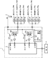
図1は、本発明に係る車両用方向指示灯制御装置の一例であるECU11の電気的構成を示すブロック図である。車両には、方向指示灯として、前部左側に設けられた主ランプFL(左前部方向指示灯)、前部右側に設けられた主ランプFR(右前部方向指示灯)、後部左側に設けられた主ランプRL(左後部方向指示灯)、後部右側に設けられた主ランプRR(右後部方向指示灯)、ならびに側部左側に設けられた副ランプSL(左側部方向指示灯)、側部右側に設けられた副ランプSR(右側部方向指示灯)、および計器盤のメーター左表示ランプML、メーター右表示ランプMRが設けられている。そして、前記ECU11には、バッテリ2から電源電圧+Bが供給されている。以上の構成は、前述の図4のECU1と同様である。
FIG. 1 is a block diagram showing an electrical configuration of an ECU 11 which is an example of a vehicular direction indicator light control apparatus according to the present invention. In the vehicle, as a direction indicator lamp, a main lamp FL (left front direction indicator lamp) provided on the front left side, a main lamp FR (right front direction indicator lamp) provided on the front right side, and provided on the rear left side Main lamp RL (left rear direction indicator lamp), main lamp RR (right rear direction indicator lamp) provided on the rear right side, sub lamp SL (left side direction indicator lamp) provided on the left side of the side, side portion A sub lamp SR (right direction indicator lamp) provided on the right side, a meter left display lamp ML on the instrument panel, and a meter right display lamp MR are provided. The ECU 11 is supplied with a power supply voltage + B from the battery 2. The above configuration is the same as that of the ECU 1 in FIG.
注目すべきは、以下の構成である。すなわち、本実施の形態では、比較的負荷電流の大きい左右の前部および後部の4つの主ランプFL,FR;RL,RRに対して、ECU11内には、個別に駆動回路DFL,DFR;DRL,DRRおよび電流検出回路MFL,MFR;MRL,MRRが設けられている。そして、例えばマイクロコンピュータを用いて構成された制御回路13(制御部)が、それぞれに対して制御および断線検知を行い、比較的負荷電流の小さい側部の副ランプSL,SRを同じ側の後部の主ランプRL,RRと並列接続し、比較的負荷電流の小さい計器盤の表示ランプML,MRを同じ側の前部の主ランプFL,FRと並列接続した。
Noteworthy is the following configuration. That is, in the present embodiment, the left and right front and rear main lamps FL, FR; RL, RR having a relatively large load current are individually provided in the ECU 11 with the drive circuits DFL, DFR; DRL. , DRR and current detection circuits MFL, MFR; MRL, MRR are provided. Then, for example, a control circuit 13 (control unit) configured by using a microcomputer performs control and disconnection detection for each, and the sub lamps SL and SR on the side having a relatively small load current are connected to the rear side on the same side. The main lamps RL and RR of the instrument panel were connected in parallel, and the display lamps ML and MR of the instrument panel with a relatively small load current were connected in parallel with the main lamps FL and FR on the same side.
具体的には、ECU11は、バッテリ2と接続するための接続端子14、前部左主ランプFLとメーター左表示ランプMLとの並列回路を接続するための接続端子15(第2左接続端子)、側部左副ランプSLと後部左主ランプRLとの並列回路を接続するための接続端子16(第1左接続端子)、前部右主ランプFRとメーター右表示ランプMRとの並列回路を接続するための接続端子17(第2右接続端子)、側部右副ランプSRと後部右主ランプRRとの並列回路を接続するための接続端子18(第1右接続端子)、及び報知手段4を接続するための接続端子19を備えている。
Specifically, the ECU 11 has a connection terminal 14 for connecting to the battery 2, and a connection terminal 15 (second left connection terminal) for connecting a parallel circuit of the front left main lamp FL and the meter left display lamp ML. A connection terminal 16 (first left connection terminal) for connecting a parallel circuit of the side left sub lamp SL and the rear left main lamp RL, and a parallel circuit of the front right main lamp FR and the meter right display lamp MR. Connection terminal 17 (second right connection terminal) for connection, connection terminal 18 (first right connection terminal) for connecting a parallel circuit of the side right auxiliary lamp SR and the rear right main lamp RR, and notification means 4 is provided.
報知手段4は、例えばLED(Light Emitting Diode)や液晶表示器等を用いて構成されている。
The notification means 4 is configured using, for example, an LED (Light Emitting Diode) or a liquid crystal display.
接続端子14は、駆動回路DFL(第2左スイッチング素子)、及び電流検出回路MFL(第2左電流検出回路)を介して接続端子15に接続されている。また、接続端子14は、駆動回路DRL(第1左スイッチング素子)、及び電流検出回路MRL(第1左電流検出回路)を介して接続端子16に接続されている。そして、接続端子14は、駆動回路DFR(第2右スイッチング素子)、及び電流検出回路MFR(第2右電流検出回路)を介して接続端子17に接続されている。さらに、接続端子14は、駆動回路DRR(第1右スイッチング素子)、及び電流検出回路MRR(第1右電流検出回路)を介して接続端子18に接続されている。
The connection terminal 14 is connected to the connection terminal 15 via a drive circuit DFL (second left switching element) and a current detection circuit MFL (second left current detection circuit). The connection terminal 14 is connected to the connection terminal 16 via a drive circuit DRL (first left switching element) and a current detection circuit MRL (first left current detection circuit). The connection terminal 14 is connected to the connection terminal 17 via a drive circuit DFR (second right switching element) and a current detection circuit MFR (second right current detection circuit). Further, the connection terminal 14 is connected to the connection terminal 18 via a drive circuit DRR (first right switching element) and a current detection circuit MRR (first right current detection circuit).
これにより、前部左主ランプFL及びメーター左表示ランプMLへの電流供給が駆動回路DFLによって制御されると共に、前部左主ランプFL及びメーター左表示ランプMLに流れる電流が電流検出回路MFLによって検出される。また、側部左副ランプSL及び後部左主ランプRLへの電流供給が駆動回路DRLによって制御されると共に、側部左副ランプSL及び後部左主ランプRLに流れる電流が電流検出回路MRLによって検出される。
Thereby, the current supply to the front left main lamp FL and the meter left display lamp ML is controlled by the drive circuit DFL, and the current flowing through the front left main lamp FL and the meter left display lamp ML is controlled by the current detection circuit MFL. Detected. The current supply to the side left sub lamp SL and the rear left main lamp RL is controlled by the drive circuit DRL, and the current flowing through the side left sub lamp SL and the rear left main lamp RL is detected by the current detection circuit MRL. Is done.
また、前部右主ランプFR及びメーター右表示ランプMRへの電流供給が駆動回路DFRによって制御されると共に、前部右主ランプFR及びメーター右表示ランプMRに流れる電流が電流検出回路MFRによって検出される。そして、側部右副ランプSR及び後部右主ランプRRへの電流供給が駆動回路DRRによって制御されると共に、側部右副ランプSR及び後部右主ランプRRに流れる電流が電流検出回路MRRによって検出される。
Further, the current supply to the front right main lamp FR and the meter right display lamp MR is controlled by the drive circuit DFR, and the current flowing through the front right main lamp FR and the meter right display lamp MR is detected by the current detection circuit MFR. Is done. The current supply to the side right sub lamp SR and the rear right main lamp RR is controlled by the drive circuit DRR, and the current flowing through the side right sub lamp SR and the rear right main lamp RR is detected by the current detection circuit MRR. Is done.
なお、本願発明では、各主ランプFL,FR;RL,RRに対して、少なくとも電流検出回路MFL,MFR;MRL,MRRが個別に設けられていればよく、駆動回路として用いられるスイッチング素子(パワートランジスタやパワーMOSFET)の容量に余裕のある場合には、例えば図2に示すように、左側の主ランプFL,RL、左側の副ランプSL、及び表示ランプMLへの駆動電流を駆動回路DFL一つでオン、オフし、右側の主ランプFR,RR、左側の副ランプSR、及び表示ランプMRへの駆動電流を駆動回路DFR一つでオン、オフするようにしてもよい。
In the present invention, at least the current detection circuits MFL, MFR; MRL, MRR need only be individually provided for the main lamps FL, FR; RL, RR, and switching elements (power When the capacity of the transistor or power MOSFET) is sufficient, for example, as shown in FIG. 2, the drive current to the left main lamps FL and RL, the left sub lamp SL, and the display lamp ML is supplied to the drive circuit DFL. Thus, the drive current to the main lamps FR and RR on the right side, the sub lamp SR on the left side, and the display lamp MR may be turned on and off with one drive circuit DFR.
具体的には、図2に示すECU11aのように、駆動回路DRL,DRRを備えず、変わりに接続端子16を電流検出回路MRLを介して駆動回路DFL(左スイッチング素子)と接続し、接続端子18を電流検出回路MRRを介して駆動回路DFR(右スイッチング素子)と接続することで、左側の主ランプFL,RL、左側の副ランプSL、及び表示ランプMLへの駆動電流を駆動回路DFL一つでオン、オフし、右側の主ランプFR,RR、左側の副ランプSR、及び表示ランプMRへの駆動電流を駆動回路DFR一つでオン、オフするようにしてもよい。
Specifically, unlike the ECU 11a shown in FIG. 2, the drive circuits DRL and DRR are not provided, but instead the connection terminal 16 is connected to the drive circuit DFL (left switching element) via the current detection circuit MRL. 18 is connected to the drive circuit DFR (right switching element) via the current detection circuit MRR, so that the drive current to the left main lamps FL and RL, the left sub lamp SL, and the display lamp ML is supplied to the drive circuit DFL. Thus, the drive current to the main lamps FR and RR on the right side, the sub lamp SR on the left side, and the display lamp MR may be turned on and off with one drive circuit DFR.
前記駆動回路DFL,DFR;DRL,DRRは、前記バッテリ2からの電源ライン12が接続された接続端子14と上述のように組合わされた各ランプFL,ML;FR,MR;RL,SL;RR,SRとの間に直列に介在されるスイッチング素子から構成されている。そして、駆動回路DFL,DFR;DRL,DRRは、例えばマイクロコンピュータを用いて構成された制御回路13の出力ポートからのON/OFF信号に応答して、左右各側のランプFL,RL,SL,ML;FR,RR,SR,MRを、それぞれ一括して点滅制御する。
The drive circuits DFL, DFR; DRL, DRR are connected to the connection terminal 14 to which the power line 12 from the battery 2 is connected, and the lamps FL, ML; FR, MR; RL, SL; , SR and switching elements interposed in series. The drive circuits DFL, DFR; DRL, DRR, for example, respond to an ON / OFF signal from the output port of the control circuit 13 configured using a microcomputer, for example, lamps FL, RL, SL, ML; FL, RR, SR, MR are controlled to blink together.
その駆動回路DFL,DFR;DRL,DRRによって供給される負荷電流は、前記電流検出回路MFL,MFR;MRL,MRRで検出され、アンプAFL,AFR;ARL,ARRで増幅されて、前記制御回路13のアナログ/デジタル変換ポートによって読込まれる。図1に示すECU11では、制御回路13の出力ポートは、駆動回路DFL,DFR;DRL,DRRに個別に対応して4つ設けられているけれども、左右各側の駆動回路DFLとDRL、DFRとDRRが共通の出力ポートからのON/OFF信号で駆動されてもよい。
Load currents supplied by the drive circuits DFL, DFR; DRL, DRR are detected by the current detection circuits MFL, MFR; MRL, MRR, amplified by the amplifiers AFL, AFR; ARL, ARR, and the control circuit 13. Read by the analog / digital conversion port. In the ECU 11 shown in FIG. 1, four output ports of the control circuit 13 are provided corresponding to the drive circuits DFL and DFR; DRL and DRR, respectively, but the drive circuits DFL and DRL and DFR on the left and right sides are provided. The DRR may be driven by an ON / OFF signal from a common output port.
上述のように構成されるECU11において、たとえば前部の主ランプFL,FRとして用いられるランプのワット数は21~28Wであり、後部の主ランプRL,RRとして用いられるランプのワット数は21Wであり、側部の副ランプSL,SRとして用いられるランプのワット数は1.6~5Wであり、計器盤の表示ランプML,MRのワット数はmWオーダーである。また、前記バッテリ2の公称電圧+Bは、たとえば12Vである。
In the ECU 11 configured as described above, for example, the wattage of the lamp used as the front main lamps FL and FR is 21 to 28 W, and the wattage of the lamp used as the rear main lamps RL and RR is 21 W. Yes, the wattage of the lamps used as the side auxiliary lamps SL and SR is 1.6 to 5 W, and the wattages of the display lamps ML and MR of the instrument panel are on the order of mW. The nominal voltage + B of the battery 2 is, for example, 12V.
そうすると、主ランプFL,FRに流れる電流は1.8~2.3Aの範囲となり、主ランプRL,RRに流れる電流は1.8Aとなり、副ランプSL,SRに流れる電流は0.1~0.4Aの範囲となる。また、表示ランプML,MRに流れる電流は数mA程度(9mA以下)であって、微小であるから無視できる。
Then, the current flowing through the main lamps FL and FR is in the range of 1.8 to 2.3 A, the current flowing through the main lamps RL and RR is 1.8 A, and the current flowing through the sub lamps SL and SR is 0.1 to 0. .4A range. Further, the current flowing through the display lamps ML and MR is about several mA (9 mA or less) and is negligible because it is very small.
そうすると、ランプが断線していない通常時において、主ランプFLと表示ランプMLとの並列回路に流れる電流及び主ランプFRと表示ランプMRとの並列回路に流れる電流、すなわち電流検出回路MFL,MFRで検出される電流は、1.8~2.3A程度の範囲となり、副ランプSLと主ランプRLとの並列回路に流れる電流及び副ランプSRと主ランプRRとの並列回路に流れる電流、すなわち電流検出回路MRL,MRRで検出される電流は、1.9~2.7A程度の範囲となる。
Then, in a normal time when the lamp is not disconnected, the current flowing in the parallel circuit of the main lamp FL and the display lamp ML and the current flowing in the parallel circuit of the main lamp FR and the display lamp MR, that is, current detection circuits MFL and MFR. The detected current is in the range of about 1.8 to 2.3 A, and the current flowing in the parallel circuit of the sub lamp SL and the main lamp RL and the current flowing in the parallel circuit of the sub lamp SR and the main lamp RR, that is, current The current detected by the detection circuits MRL and MRR is in the range of about 1.9 to 2.7 A.
これにより、通常時において電流検出回路MFL,MFR,MRL,MRRで検出される電流の最小値は、図3に示すように、電圧+Bが12Vのときに1.8Aとなる。ここで、バッテリ2の出力電圧+Bは、9V程度まで低下する場合があり、このときに電流検出回路MFL,MFR,MRL,MRRで検出される電流の最小値は1.3A程度となる。
As a result, the minimum value of the current detected by the current detection circuits MFL, MFR, MRL, and MRR in a normal state is 1.8 A when the voltage + B is 12 V as shown in FIG. Here, the output voltage + B of the battery 2 may drop to about 9 V, and the minimum value of the current detected by the current detection circuits MFL, MFR, MRL, and MRR at this time is about 1.3 A.
そうすると、電流検出回路MFL,MFR,MRL,MRRで検出される電流値に基づいて主ランプFL,FR,RL,RRの断線を検知するための閾値Vthは、バッテリ2の出力電圧下限において、ランプが断線していないときに流れる電流の最小値である1.3Aを下回る値を設定する必要がある。
Then, the threshold Vth for detecting disconnection of the main lamps FL, FR, RL, RR based on the current values detected by the current detection circuits MFL, MFR, MRL, MRR is set at the lower limit of the output voltage of the battery 2. It is necessary to set a value lower than 1.3 A, which is the minimum value of the current that flows when is not disconnected.
また、主ランプFL,FR,RL,RRのうちいずれかが断線した場合、電流検出回路MFL,MFR,MRL,MRRで検出される電流の最大値は、出力電圧+Bが12Vの場合において0.4Aとなる。そうすると、閾値Vthは、バッテリ2の出力電圧上限において、主ランプFL,FR,RL,RRのうちいずれかが断線したときに流れる電流の最大値である0.4Aを上回る値を設定する必要がある。
When any of the main lamps FL, FR, RL, RR is disconnected, the maximum value of the current detected by the current detection circuits MFL, MFR, MRL, MRR is 0. When the output voltage + B is 12V. 4A. Then, the threshold value Vth needs to be set to a value exceeding 0.4 A, which is the maximum value of the current that flows when any of the main lamps FL, FR, RL, RR is disconnected at the upper limit of the output voltage of the battery 2. is there.
そこで、断線検知の閾値Vthとしては、例えば1.1~1.2Aが設定されている。そして、制御回路13は、上述の各ランプの点灯制御時に、負荷電流が閾値Vth未満となると、例えば報知手段4によって運転者へ断線を報知させる。この場合、報知手段4を制御回路13に接続する接続端子19や制御回路13における報知手段4への信号出力ポートが報知回路の一例に相当している。
Therefore, for example, 1.1 to 1.2 A is set as the threshold value Vth for detecting disconnection. Then, when the load current becomes less than the threshold value Vth during the lighting control of each lamp described above, the control circuit 13 notifies the driver of the disconnection by, for example, the notification unit 4. In this case, the connection terminal 19 that connects the notification means 4 to the control circuit 13 and the signal output port to the notification means 4 in the control circuit 13 correspond to an example of the notification circuit.
このように構成することで、制御回路13が断線検知を行うにあたって、4つの主ランプFL,FR;RL,RRに個別に電流検出回路MFL,MFR;MRL,MRRを設けて断線検知を行うので、大まかに負荷電流が流れているか否かの判定となり、仕様の違いによって該主ランプFL,FR;RL,RRのワット数に差が生じても、或いはバッテリ2の電源電圧+Bの変動や電流検出回路MFL,MFR;MRL,MRRの誤差に対しても、共通の閾値を用いて正確に断線検知を行うことができる。
With this configuration, when the control circuit 13 performs disconnection detection, the four main lamps FL, FR; RL, RR are individually provided with current detection circuits MFL, MFR; MRL, MRR to detect disconnection. Whether or not the load current is flowing roughly is determined, and even if there is a difference in the wattage of the main lamps FL, FR; RL, RR due to the difference in specifications, or the fluctuation or current of the power supply voltage + B of the battery 2 With respect to errors in the detection circuits MFL, MFR; MRL, MRR, disconnection detection can be accurately performed using a common threshold value.
すなわち、図3で示すように、主ランプFL,FR,RL,RRのいずれも断線していない通常負荷時の負荷電流と断線時の負荷電流との間には充分な差W2が生じることとなり、前記閾値に多少のばらつきが生じても、正確に断線検知を行うことができる。これによって、仕様の違いに対して、煩雑な調整を伴うことなく、共通のECU11を使用することができる。また、上述の従来技術で必要となるバッテリ2の電源電圧+Bを検出する前記電圧検出回路5や、制御回路3における制御用のテーブルなどを不要にすることができる。
That is, as shown in FIG. 3, there is a sufficient difference W2 between the load current at the normal load when none of the main lamps FL, FR, RL, RR is disconnected and the load current at the disconnection. Even if there is some variation in the threshold value, it is possible to accurately detect disconnection. As a result, the common ECU 11 can be used without complicated adjustment for the difference in specifications. In addition, the voltage detection circuit 5 for detecting the power supply voltage + B of the battery 2 required in the above-described conventional technology, the control table in the control circuit 3, and the like can be eliminated.
また、前部の主ランプFL,FRと後部の主ランプRL,RRとの内、前述のように一般に前部の主ランプFL,FRの方がワット数が大きいので、側部の副ランプSL,SRも合わせて点滅を制御するにあたって、ワット数が小さいながらも、計器盤の表示ランプML,MRよりは数段ワット数の大きな側部の副ランプSL,SRを同じ側の後部の主ランプRL,RRと並列に接続することで、4つの電流検出回路MFL,MFR;MRL,MRR間のバランスを高め、断線検知の精度をより向上することができる。
Further, among the front main lamps FL and FR and the rear main lamps RL and RR, as described above, the front main lamps FL and FR generally have a larger wattage, so the side sub lamp SL. , SR when controlling the blinking, the sub lamps SL, SR on the side having a larger wattage than the display lamps ML, MR on the instrument panel are connected to the rear main lamp on the same side, although the wattage is small. By connecting in parallel with RL and RR, the balance between the four current detection circuits MFL and MFR; MRL and MRR can be increased, and the accuracy of disconnection detection can be further improved.
さらにまた、計器盤の表示ランプML,MRは、ワット数が非常に小さいので、前記副ランプSL,SRが接続された後部の主ランプRL,RRと並列に接続されてもよいが、一般に後部よりワット数が大きい前部の主ランプFL,FRと並列に接続することで、4つの電流検出回路MFL,MFR;MRL,MRR間のバランスを、より一層高めることができる。
Furthermore, since the display lamps ML and MR of the instrument panel have a very small wattage, they may be connected in parallel with the rear main lamps RL and RR to which the sub lamps SL and SR are connected. By connecting in parallel with the front main lamps FL and FR having a larger wattage, the balance between the four current detection circuits MFL and MFR; MRL and MRR can be further increased.
さらにまた、断線検知の閾値を、1.1~1.2Aとすることで、バッテリ2の電源電圧+Bが12Vの場合に、広く用いられる20~30W程度のランプに好適に対応することができる。
Furthermore, by setting the disconnection detection threshold value to 1.1 to 1.2 A, when the power supply voltage + B of the battery 2 is 12 V, it is possible to suitably cope with a widely used lamp of about 20 to 30 W. .
即ち、本発明の一局面に係る車両用方向指示灯制御装置は、車両の左側の、前部に設けられる左前部方向指示灯、後部に設けられる左後部方向指示灯、及び側部に設けられる左側部方向指示灯と、前記車両の右側の、前部に設けられる右前部方向指示灯、後部に設けられる右後部方向指示灯、及び側部に設けられる右側部方向指示灯とのうち、主ランプである前記左前部方向指示灯、前記左後部方向指示灯、前記右前部方向指示灯、及び前記右後部方向指示灯の断線を報知する報知回路と、前記左側の各方向指示灯と、前記右側の各方向指示灯とを、それぞれ点灯させる駆動回路と、主ランプである前記左前部方向指示灯、前記左後部方向指示灯、前記右前部方向指示灯、及び前記右後部方向指示灯にそれぞれ対応して設けられ、それぞれ当該対応する方向指示灯に流れる負荷電流を検出するための複数の電流検出回路と、運転者の操作に応答して、前記左側の各方向指示灯と、前記右側の各方向指示灯とのうちいずれか一方を前記駆動回路によって点灯させるとともに、点灯させている方向指示灯に対応した各電流検出回路の検出結果を予め定める共通の閾値と比較し、各検出結果のいずれかが閾値未満となると、前記報知手段によって前記運転者に断線を報知させる制御部とを含み、前記左側部方向指示灯は、前記車両の左側の主ランプである前記左前部方向指示灯及び前記左後部方向指示灯のいずれか一方と並列接続されて並列回路にされ、前記左側部方向指示灯と並列接続された方向指示灯に対応して設けられた電流検出回路は、前記左側部方向指示灯を含む並列回路に流れる負荷電流を検出し、前記右側部方向指示灯は、前記車両の右側の主ランプである前記右前部方向指示灯及び前記右後部方向指示灯のいずれか一方と並列接続されて並列回路にされ、前記右側部方向指示灯と並列接続された方向指示灯に対応して設けられた電流検出回路は、前記右側部方向指示灯を含む並列回路に流れる負荷電流を検出する。
That is, the vehicle direction indicator lamp control device according to one aspect of the present invention is provided on the left side of the vehicle, the left front direction indicator lamp provided at the front, the left rear direction indicator lamp provided at the rear, and the side. Of the left direction indicator lamp, the right front direction indicator lamp provided at the front of the right side of the vehicle, the right rear direction indicator lamp provided at the rear, and the right side direction indicator lamp provided at the side. The left front direction indicator lamp, which is a lamp, the left rear direction indicator lamp, the right front direction indicator lamp, and a notification circuit that notifies disconnection of the right rear direction indicator lamp, the left direction indicator lamps, Each of the right direction indicator lamps is turned on to the drive circuit to be turned on, and the left front direction indicator lamp, the left rear direction indicator lamp, the right front direction indicator lamp, and the right rear direction indicator lamp, which are main lamps, respectively. Correspondingly provided, each A plurality of current detection circuits for detecting a load current flowing through the corresponding direction indicator lamp, and each of the left direction indicator lamp and the right direction indicator lamp in response to a driver's operation. Either one is turned on by the drive circuit, and the detection result of each current detection circuit corresponding to the turned direction indicator lamp is compared with a predetermined common threshold, and when any of the detection results is less than the threshold. And a control unit for notifying the driver of the disconnection by the notification means, wherein the left side direction indicator lamp includes a left front direction indicator lamp and a left rear direction indicator lamp which are main left side lamps of the vehicle. A current detection circuit provided corresponding to the direction indicator lamp connected in parallel to either one of the parallel direction and the left side direction indicator lamp is a parallel circuit including the left side direction indicator lamp. The right side direction indicator lamp is connected in parallel with either the right front direction indicator lamp or the right rear direction indicator lamp, which is the right main lamp of the vehicle, to form a parallel circuit. The current detection circuit provided corresponding to the direction indicator lamp connected in parallel with the right side direction indicator lamp detects a load current flowing in the parallel circuit including the right side direction indicator lamp.
上記の構成によれば、車両の方向指示灯の点滅を制御するとともに、前記方向指示灯の断線を検知すると、報知手段によって運転者に報知するようにした制御装置において、左右それぞれの側で、少なくとも前部、後部および側部に設けられる前記方向指示灯の内、比較的負荷電流の大きい左右の前部および後部の4つの方向指示灯に対して、個別に電流検出回路を設けて、それぞれで断線検知を行うようにし、比較的負荷電流の小さい側部の方向指示灯は、同じ側の前部または後部の方向指示灯と並列接続される。
According to the above configuration, in the control device that controls the blinking of the direction indicator lamp of the vehicle and detects the disconnection of the direction indicator lamp, on the left and right sides in the control device that notifies the driver by the notification means, Current detection circuits are individually provided for the four direction indicator lamps on the left and right front and rear parts having a relatively large load current among the direction indicator lamps provided on at least the front part, the rear part, and the side part. The disconnection detection is performed at the side, and the direction indicator lamp on the side having a relatively small load current is connected in parallel with the front or rear direction indicator lamp on the same side.
したがって、点灯させている状態での負荷電流を所定の閾値と比較し、断線検知を行うにあたって、主要な左右の前部および後部の4つの方向指示灯に対応して個別に電流検出回路を設けて断線検知を行うので、大まかに負荷電流が流れているか否かの判定となり、前記仕様の違いによって方向指示灯のワット数(負荷電流)に差が生じても、或いはバッテリ電圧の変動や電流検出回路の誤差に対しても、共通の閾値を用いて正確に断線検知を行うことができる。これによって、仕様の違いに対して、煩雑な調整を伴うことなく、共通の車輌用方向指示灯制御装置を使用することができる。また、バッテリ電圧を検出する回路を不要にすることができる。
Therefore, when detecting the disconnection by comparing the load current in the lit state with a predetermined threshold value, a current detection circuit is provided for each of the four main front and rear direction indicators. Therefore, it is determined whether or not the load current is flowing, and even if there is a difference in the wattage (load current) of the direction indicator lamp due to the difference in the specifications, the fluctuation of the battery voltage or the current Even for errors in the detection circuit, disconnection detection can be accurately performed using a common threshold. This makes it possible to use a common vehicular direction indicator light control device without complicated adjustment for differences in specifications. Further, a circuit for detecting the battery voltage can be eliminated.
また、前記車両の左側の主ランプである前記左前部方向指示灯及び前記左後部方向指示灯のいずれか一方と前記左側部方向指示灯との並列回路が接続される第1左接続端子と、前記車両の左側の他方の主ランプが接続される第2左接続端子と、前記車両の右側の主ランプである前記右前部方向指示灯及び前記右後部方向指示灯のいずれか一方と前記右側部方向指示灯との並列回路が接続される第1右接続端子と、前記車両の右側の他方の主ランプが接続される第2右接続端子とをさらに備え、前記駆動回路は、前記第1左接続端子及び前記第2左接続端子へ負荷電流を供給することにより、左前部方向指示灯、前記左後部方向指示灯、及び前記左側部方向指示灯を点灯させる左側駆動回路と、前記第1右接続端子及び前記第2右接続端子へ負荷電流を供給することにより、右前部方向指示灯、前記右後部方向指示灯、及び前記右側部方向指示灯を点灯させる右側駆動回路とを含み、前記複数の電流検出回路は、前記第1左接続端子を流れる負荷電流を検出する第1左電流検出回路、前記第2左接続端子を流れる負荷電流を検出する第2左電流検出回路、前記第1右接続端子を流れる負荷電流を検出する第1右電流検出回路、及び前記第2右接続端子を流れる負荷電流を検出する第2右電流検出回路であることが好ましい。
Further, a first left connection terminal to which a parallel circuit of either the left front direction indicator lamp or the left rear direction indicator lamp which is a main lamp on the left side of the vehicle and the left side direction indicator lamp is connected, A second left connection terminal to which the other main lamp on the left side of the vehicle is connected; one of the right front direction indicator lamp and the right rear direction indicator lamp which are main lamps on the right side of the vehicle; The driving circuit further includes a first right connection terminal to which a parallel circuit with a direction indicator lamp is connected, and a second right connection terminal to which the other main lamp on the right side of the vehicle is connected. A left driving circuit for lighting a left front direction indicator lamp, the left rear direction indicator lamp, and the left side direction indicator lamp by supplying a load current to the connection terminal and the second left connection terminal; and the first right To the connection terminal and the second right connection terminal A plurality of current detection circuits including the first left direction indicator lamp, the right rear direction indicator lamp, and a right side drive circuit that lights the right side direction indicator lamp. A first left current detection circuit for detecting a load current flowing through the connection terminal; a second left current detection circuit for detecting a load current flowing through the second left connection terminal; and a first current detection circuit detecting a load current flowing through the first right connection terminal. Preferably, the first right current detection circuit and the second right current detection circuit that detects a load current flowing through the second right connection terminal.
この構成によれば、第1左接続端子に、左前部方向指示灯及び左後部方向指示灯のいずれか一方と左側部方向指示灯との並列回路が接続され、第1右接続端子に、右前部方向指示灯及び右後部方向指示灯のいずれか一方と右側部方向指示灯との並列回路が接続されるので、第1左接続端子及び第1右接続端子の2端子で4つの方向指示灯を点灯させることができる結果、接続端子数を低減することが可能となる。
According to this configuration, the parallel circuit of either the left front direction indicator lamp or the left rear direction indicator lamp and the left side direction indicator lamp is connected to the first left connection terminal, and the right front terminal is connected to the right front terminal. Since the parallel circuit of either one of the direction indicator lamp and the right rear direction indicator lamp and the right side direction indicator lamp is connected, four direction indicator lamps are provided by two terminals of the first left connection terminal and the first right connection terminal. As a result, the number of connection terminals can be reduced.
そして、第1左接続端子に、断線検知の対象となる左前部方向指示灯及び左後部方向指示灯のいずれか一方と、断線検知の対象ではなくかつ左前部方向指示灯及び左後部方向指示灯より負荷電流が少ない左側部方向指示灯との並列回路が接続され、この並列回路を流れる電流が第1左電流検出回路で検出されるので、左側部方向指示灯を他の方向指示灯と並列接続して接続端子数を低減しつつ、第1左電流検出回路で検出される電流検出値への、左側部方向指示灯による影響が低減される。
Then, the first left connection terminal is connected to either the left front direction indicator lamp or the left rear direction indicator lamp that is subject to disconnection detection, and is not the subject of disconnection detection, and the left front direction indicator lamp or left rear direction indicator lamp A parallel circuit is connected to the left direction indicator lamp with a smaller load current, and the current flowing through the parallel circuit is detected by the first left current detection circuit, so the left side direction indicator lamp is parallel to the other direction indicator lamps. While reducing the number of connection terminals by connecting, the influence of the left direction indicator lamp on the current detection value detected by the first left current detection circuit is reduced.
同様に、右側部方向指示灯を他の方向指示灯と並列接続して接続端子数を低減しつつ、第1右電流検出回路で検出される電流検出値への、右側部方向指示灯による影響が低減される。
Similarly, the right side direction indicator lamp affects the current detection value detected by the first right current detection circuit while reducing the number of connection terminals by connecting the right side direction indicator lamp in parallel with other direction indicator lights. Is reduced.
このように、接続端子数の増大を抑制しつつ、第1左電流検出回路及び第1右電流検出回路で検出される電流検出値における、左側部方向指示灯及び右側部方向指示灯の負荷電流の影響が低減される結果、制御部による断線の判定精度が向上する。
As described above, the load currents of the left direction indicator lamp and the right direction indicator lamp in the current detection values detected by the first left current detection circuit and the first right current detection circuit while suppressing an increase in the number of connection terminals. As a result, the determination accuracy of disconnection by the control unit is improved.
また、前記左前部方向指示灯及び前記左後部方向指示灯のうち、前記左側部方向指示灯と並列接続されていない方向指示灯には、車両の計器盤に設けられるメーター左表示ランプが並列接続されて並列回路にされ、前記メーター左表示ランプと並列接続された方向指示灯に対応して設けられた電流検出回路は、前記メーター左表示ランプを含む並列回路に流れる負荷電流を検出し、前記右前部方向指示灯及び前記右後部方向指示灯のうち、前記右側部方向指示灯と並列接続されていない方向指示灯には、車両の計器盤に設けられるメーター右表示ランプが並列接続され、前記メーター右表示ランプと並列接続された方向指示灯に対応して設けられた電流検出回路は、前記メーター右表示ランプを含む並列回路に流れる負荷電流を検出することが好ましい。
Further, of the left front direction indicator lamp and the left rear direction indicator lamp, a meter left display lamp provided on the instrument panel of the vehicle is connected in parallel to the direction indicator lamp that is not connected in parallel with the left side direction indicator lamp. And a current detection circuit provided in correspondence with the direction indicator lamp connected in parallel with the meter left indicator lamp to detect a load current flowing in the parallel circuit including the meter left indicator lamp. Of the right front direction indicator lamp and the right rear direction indicator lamp, the direction indicator lamp not connected in parallel with the right side direction indicator lamp is connected in parallel with a meter right display lamp provided on the instrument panel of the vehicle, A current detection circuit provided corresponding to the direction indicator lamp connected in parallel with the meter right indicator lamp detects a load current flowing in the parallel circuit including the meter right indicator lamp. It is preferred.
上記の構成によれば、計器盤に設けられる方向指示灯の表示ランプも合わせて点滅を制御するにあたって、その計器盤の表示ランプが、同じ側の前部または後部の方向指示灯の内、側部の方向指示灯が接続されていない方に並列に接続される。
According to the above configuration, when controlling the blinking of the indicator lamp provided on the instrument panel as well, the indicator lamp of the instrument panel is connected to the front or rear direction indicator lamp on the same side. It is connected in parallel to the direction where the direction indicator lamp of the part is not connected.
したがって、前部または後部の方向指示灯より負荷電流が少なくかつ断線検出の対象となっていない計器盤の表示ランプが、前部または後部の方向指示灯と並列接続され、この並列回路を流れる電流が電流検出回路によって検出されるので、電流検出回路による電流検出値に与える影響を小さくすることができる。
Therefore, the indicator lamp of the instrument panel that has less load current than the front or rear direction indicator lamp and is not subject to disconnection detection is connected in parallel with the front or rear direction indicator lamp, and the current flowing through this parallel circuit Is detected by the current detection circuit, the influence of the current detection circuit on the current detection value can be reduced.
また、前記第2左接続端子には、前記左側の他方の主ランプと車両の計器盤に設けられるメーター左表示ランプとの並列回路が接続され、前記第2右接続端子には、前記右側の他方の主ランプと車両の計器盤に設けられるメーター右表示ランプとの並列回路が接続されることが好ましい。
The second left connection terminal is connected to a parallel circuit of the other left main lamp and a meter left display lamp provided on the instrument panel of the vehicle, and the second right connection terminal is connected to the right It is preferable to connect a parallel circuit of the other main lamp and a meter right display lamp provided on the instrument panel of the vehicle.
この構成によれば、左右の主ランプと、主ランプより負荷電流が少なくかつ断線検出の対象となっていない計器盤の表示ランプとが並列接続され、この並列回路を流れる電流が電流検出回路によって検出されるので、表示ランプを接続するために接続端子を増加させることなく、かつ電流検出回路による電流検出値に与える影響の増大を低減することができる。
According to this configuration, the left and right main lamps are connected in parallel to the display lamps of the instrument panel that have less load current than the main lamps and are not subject to disconnection detection, and the current flowing through the parallel circuit is caused by the current detection circuit. Therefore, it is possible to reduce the increase in the influence on the current detection value by the current detection circuit without increasing the number of connection terminals for connecting the display lamp.
さらにまた、前記左側部方向指示灯は、前記左後部方向指示灯と並列接続され、前記右側部方向指示灯は、前記右後部方向指示灯と並列接続され、前記メーター左表示ランプは、前記左前部方向指示灯と並列接続され、前記メーター右表示ランプは、前記右前部方向指示灯と並列接続されることが好ましい。
Furthermore, the left side direction indicator lamp is connected in parallel with the left rear direction indicator lamp, the right side direction indicator lamp is connected in parallel with the right rear direction indicator lamp, and the meter left indicator lamp is the left front indicator lamp. Preferably, the meter right display lamp is connected in parallel with the right front direction indicator lamp.
上記の構成によれば、前部の方向指示灯と後部の方向指示灯との内、一般に前部の方向指示灯の方がワット数が大きいので、ワット数が小さいながらも、計器盤の方向指示灯よりは数段ワット数の大きな側部の方向指示灯を、後部の方向指示灯と並列に接続することで、前記4つの電流検出回路間のバランスを高め、断線検知の精度をより向上することができる。
According to the above configuration, among the front direction indicator lamp and the rear direction indicator lamp, the front direction indicator lamp generally has a larger wattage. By connecting a directional indicator lamp on the side, which is several watts larger than the indicator lamp, in parallel with the directional indicator lamp on the rear side, the balance between the four current detection circuits is improved and the accuracy of disconnection detection is further improved. can do.
また、前記左側駆動回路は、前記第1左電流検出回路を介して前記第1左接続端子へ負荷電流を供給する第1左スイッチング素子と、前記第2左電流検出回路を介して前記第2左接続端子へ負荷電流を供給する第2左スイッチング素子とを含み、前記右側駆動回路は、前記第1右電流検出回路を介して前記第1右接続端子へ負荷電流を供給する第1右スイッチング素子と、前記第2右電流検出回路を介して前記第2右接続端子へ負荷電流を供給する第2右スイッチング素子とを含むことが好ましい。
The left driving circuit includes a first left switching element for supplying a load current to the first left connection terminal via the first left current detection circuit, and the second left switching circuit via the second left current detection circuit. A second left switching element for supplying a load current to the left connection terminal, wherein the right drive circuit supplies a load current to the first right connection terminal via the first right current detection circuit. It is preferable that an element and a second right switching element for supplying a load current to the second right connection terminal via the second right current detection circuit are included.
また、前記左側駆動回路は、前記第1左電流検出回路を介して前記第1左接続端子へ負荷電流を供給すると共に前記第2左電流検出回路を介して前記第2左接続端子へ並列に負荷電流を供給する左スイッチング素子であり、前記右側駆動回路は、前記第1右電流検出回路を介して前記第1右接続端子へ負荷電流を供給すると共に前記第2右電流検出回路を介して前記第2右接続端子へ並列に負荷電流を供給する右スイッチング素子であることが好ましい。
The left driving circuit supplies a load current to the first left connection terminal via the first left current detection circuit and is connected in parallel to the second left connection terminal via the second left current detection circuit. A left switching element for supplying a load current, wherein the right drive circuit supplies a load current to the first right connection terminal via the first right current detection circuit and via the second right current detection circuit; Preferably, the right switching element supplies a load current in parallel to the second right connection terminal.
この構成によれば、スイッチング素子の数を接続端子数より少なくすることができるので、コストの低減が可能となる。
According to this configuration, since the number of switching elements can be made smaller than the number of connection terminals, the cost can be reduced.
また、前記左前部方向指示灯及び前記右前部方向指示灯としては、負荷電流が1.8~2.3Aの範囲内となるランプが用いられ、前記左後部方向指示灯及び前記右後部方向指示灯としては、負荷電流が1.8となるランプが用いられ、前記左側部方向指示灯及び前記右側部方向指示灯としては、負荷電流が0.1~0.4Aの範囲内となるランプが用いられ、前記メーター左表示ランプ及び前記メーター右表示ランプとしては、負荷電流が9mA以下のランプが用いられ、前記閾値は、1.1~1.2Aの範囲内で設定されることが好ましい。
In addition, as the left front direction indicator lamp and the right front direction indicator lamp, a lamp having a load current within a range of 1.8 to 2.3 A is used, and the left rear direction indicator lamp and the right rear direction indicator lamp are used. As the lamp, a lamp having a load current of 1.8 is used. As the left side direction indicator lamp and the right side direction indicator lamp, a lamp having a load current within a range of 0.1 to 0.4 A is used. As the meter left display lamp and the meter right display lamp, a lamp having a load current of 9 mA or less is preferably used, and the threshold is preferably set within a range of 1.1 to 1.2 A.
上記の構成によれば、バッテリ電圧が12Vで、広く用いられる20~30W程度のランプに対応することができる。
According to the above configuration, the battery voltage is 12 V, and it is possible to cope with a widely used lamp of about 20 to 30 W.
本発明の車両用方向指示灯制御装置は、以上のように、車両の方向指示灯の点滅を制御するとともに、前記方向指示灯の断線を検知すると、報知手段によって運転者に報知するようにした制御装置において、左右それぞれの側で、少なくとも前部、後部および側部に設けられる前記方向指示灯の内、比較的負荷電流の大きい左右の前部および後部の4つの方向指示灯に対して、個別に電流検出回路を設けて、それぞれで断線検知を行うようにし、比較的負荷電流の小さい側部の方向指示灯は、同じ側の前部または後部の方向指示灯と並列接続する。
The vehicle direction indicator lamp control device according to the present invention controls the blinking of the direction indicator lamp of the vehicle as described above, and when the disconnection of the direction indicator lamp is detected, the driver is notified by the notification means. In the control device, on each of the left and right sides, among the direction indicator lamps provided at least at the front, rear, and side portions, the left and right front and rear direction indicator lights having a relatively large load current, A current detection circuit is provided individually to detect disconnection, and the direction indicator lamps on the side with a relatively small load current are connected in parallel with the front or rear direction indicator lamps on the same side.
それゆえ、大まかに負荷電流が流れているか否かの判定となり、前記仕様の違いによって方向指示灯のワット数に差が生じても、或いはバッテリ電圧の変動や電流検出回路の誤差に対しても、共通の閾値を用いて正確に断線検知を行うことができる。これによって、仕様の違いに対して、煩雑な調整を伴うことなく、共通のECUを使用することができる。また、バッテリ電圧を検出する回路を不要にすることができる。
Therefore, whether or not the load current is flowing roughly is determined, and even if the difference in the wattage of the direction indicator lamp due to the difference in the specifications, or the fluctuation of the battery voltage or the error of the current detection circuit, The disconnection can be detected accurately using a common threshold. Thereby, it is possible to use a common ECU without complicated adjustment for the difference in specifications. Further, a circuit for detecting the battery voltage can be eliminated.
Claims (8)
- 車両の左側の、前部に設けられる左前部方向指示灯、後部に設けられる左後部方向指示灯、及び側部に設けられる左側部方向指示灯と、前記車両の右側の、前部に設けられる右前部方向指示灯、後部に設けられる右後部方向指示灯、及び側部に設けられる右側部方向指示灯とのうち、主ランプである前記左前部方向指示灯、前記左後部方向指示灯、前記右前部方向指示灯、及び前記右後部方向指示灯の断線を報知する報知回路と、
前記左側の各方向指示灯と、前記右側の各方向指示灯とを、それぞれ点灯させる駆動回路と、
主ランプである前記左前部方向指示灯、前記左後部方向指示灯、前記右前部方向指示灯、及び前記右後部方向指示灯にそれぞれ対応して設けられ、それぞれ当該対応する方向指示灯に流れる負荷電流を検出するための複数の電流検出回路と、
運転者の操作に応答して、前記左側の各方向指示灯と、前記右側の各方向指示灯とのうちいずれか一方を前記駆動回路によって点灯させるとともに、点灯させている方向指示灯に対応した各電流検出回路の検出結果を予め定める共通の閾値と比較し、各検出結果のいずれかが閾値未満となると、前記報知手段によって前記運転者に断線を報知させる制御部とを含み、
前記左側部方向指示灯は、前記車両の左側の主ランプである前記左前部方向指示灯及び前記左後部方向指示灯のいずれか一方と並列接続されて並列回路にされ、
前記左側部方向指示灯と並列接続された方向指示灯に対応して設けられた電流検出回路は、前記左側部方向指示灯を含む並列回路に流れる負荷電流を検出し、
前記右側部方向指示灯は、前記車両の右側の主ランプである前記右前部方向指示灯及び前記右後部方向指示灯のいずれか一方と並列接続されて並列回路にされ、
前記右側部方向指示灯と並列接続された方向指示灯に対応して設けられた電流検出回路は、前記右側部方向指示灯を含む並列回路に流れる負荷電流を検出すること
を特徴とする車両用方向指示灯制御装置。 A left front direction indicator lamp provided at the front of the left side of the vehicle, a left rear direction indicator lamp provided at the rear, a left side direction indicator lamp provided at the side, and a front part of the right side of the vehicle. Of the right front direction indicator lamp, the right rear direction indicator lamp provided at the rear, and the right side direction indicator lamp provided at the side, the left front direction indicator lamp that is a main lamp, the left rear direction indicator lamp, A notification circuit for notifying a disconnection of the right front direction indicator lamp and the right rear direction indicator lamp;
Each of the left direction indicator lamps and the right side direction indicator lamps, respectively, drive circuits for lighting,
A load that is provided corresponding to each of the left front direction indicator lamp, the left rear direction indicator lamp, the right front direction indicator lamp, and the right rear direction indicator lamp, which are main lamps, and flows to the corresponding direction indicator lamp. A plurality of current detection circuits for detecting current;
In response to the driver's operation, either one of the left direction indicator lamp and the right direction indicator lamp is turned on by the drive circuit and corresponds to the turned direction indicator lamp. A control unit that compares the detection result of each current detection circuit with a predetermined common threshold value, and when any of the detection results is less than the threshold value, causes the driver to notify the driver of a disconnection;
The left side direction indicator lamp is connected in parallel with either the left front direction indicator lamp or the left rear direction indicator lamp, which is the left main lamp of the vehicle, to form a parallel circuit,
The current detection circuit provided corresponding to the direction indicator lamp connected in parallel with the left side direction indicator lamp detects a load current flowing in the parallel circuit including the left side direction indicator lamp,
The right side direction indicator lamp is connected in parallel with any one of the right front direction indicator lamp and the right rear direction indicator lamp which are the main lamps on the right side of the vehicle to form a parallel circuit,
A current detection circuit provided corresponding to a direction indicator lamp connected in parallel with the right side direction indicator lamp detects a load current flowing in a parallel circuit including the right side direction indicator lamp. Direction indicator control device. - 前記車両の左側の主ランプである前記左前部方向指示灯及び前記左後部方向指示灯のいずれか一方と前記左側部方向指示灯との並列回路が接続される第1左接続端子と、
前記車両の左側の他方の主ランプが接続される第2左接続端子と、
前記車両の右側の主ランプである前記右前部方向指示灯及び前記右後部方向指示灯のいずれか一方と前記右側部方向指示灯との並列回路が接続される第1右接続端子と、
前記車両の右側の他方の主ランプが接続される第2右接続端子とをさらに備え、
前記駆動回路は、
前記第1左接続端子及び前記第2左接続端子へ負荷電流を供給することにより、左前部方向指示灯、前記左後部方向指示灯、及び前記左側部方向指示灯を点灯させる左側駆動回路と、
前記第1右接続端子及び前記第2右接続端子へ負荷電流を供給することにより、右前部方向指示灯、前記右後部方向指示灯、及び前記右側部方向指示灯を点灯させる右側駆動回路とを含み、
前記複数の電流検出回路は、
前記第1左接続端子を流れる負荷電流を検出する第1左電流検出回路、
前記第2左接続端子を流れる負荷電流を検出する第2左電流検出回路、
前記第1右接続端子を流れる負荷電流を検出する第1右電流検出回路、
及び前記第2右接続端子を流れる負荷電流を検出する第2右電流検出回路であること
を特徴とする請求項1記載の車両用方向指示灯制御装置。 A first left connection terminal to which a parallel circuit of either the left front direction indicator lamp or the left rear direction indicator lamp, which is a left main lamp of the vehicle, and the left side direction indicator lamp is connected;
A second left connection terminal to which the other main lamp on the left side of the vehicle is connected;
A first right connection terminal to which a parallel circuit of either the right front direction indicator lamp or the right rear direction indicator lamp, which is a main lamp on the right side of the vehicle, and the right side direction indicator lamp is connected;
A second right connection terminal to which the other main lamp on the right side of the vehicle is connected;
The drive circuit is
A left driving circuit for lighting a left front direction indicator lamp, the left rear direction indicator lamp, and the left side direction indicator lamp by supplying a load current to the first left connection terminal and the second left connection terminal;
A right drive circuit for lighting a right front direction indicator lamp, a right rear direction indicator lamp, and a right side direction indicator lamp by supplying a load current to the first right connection terminal and the second right connection terminal; Including
The plurality of current detection circuits include:
A first left current detection circuit for detecting a load current flowing through the first left connection terminal;
A second left current detection circuit for detecting a load current flowing through the second left connection terminal;
A first right current detection circuit for detecting a load current flowing through the first right connection terminal;
And a second right current detection circuit that detects a load current flowing through the second right connection terminal. - 前記左前部方向指示灯及び前記左後部方向指示灯のうち、前記左側部方向指示灯と並列接続されていない方向指示灯には、車両の計器盤に設けられるメーター左表示ランプが並列接続されて並列回路にされ、
前記メーター左表示ランプと並列接続された方向指示灯に対応して設けられた電流検出回路は、前記メーター左表示ランプを含む並列回路に流れる負荷電流を検出し、
前記右前部方向指示灯及び前記右後部方向指示灯のうち、前記右側部方向指示灯と並列接続されていない方向指示灯には、車両の計器盤に設けられるメーター右表示ランプが並列接続され、
前記メーター右表示ランプと並列接続された方向指示灯に対応して設けられた電流検出回路は、前記メーター右表示ランプを含む並列回路に流れる負荷電流を検出すること
を特徴とする請求項1記載の車両用方向指示灯制御装置。 Of the left front direction indicator lamp and the left rear direction indicator lamp, a direction indicator lamp that is not connected in parallel with the left side direction indicator lamp is connected in parallel with a meter left display lamp provided on the instrument panel of the vehicle. Parallel circuit,
The current detection circuit provided corresponding to the direction indicator lamp connected in parallel with the meter left indicator lamp detects a load current flowing in the parallel circuit including the meter left indicator lamp,
Of the right front direction indicator lamp and the right rear direction indicator lamp, a direction indicator lamp that is not connected in parallel with the right side direction indicator lamp is connected in parallel with a meter right display lamp provided on the instrument panel of the vehicle,
The current detection circuit provided corresponding to the direction indicator lamp connected in parallel with the meter right indicator lamp detects a load current flowing in a parallel circuit including the meter right indicator lamp. Vehicle direction indicator lamp control device. - 前記第2左接続端子には、前記左側の他方の主ランプと車両の計器盤に設けられるメーター左表示ランプとの並列回路が接続され、
前記第2右接続端子には、前記右側の他方の主ランプと車両の計器盤に設けられるメーター右表示ランプとの並列回路が接続されること
を特徴とする請求項2記載の車両用方向指示灯制御装置。 The second left connection terminal is connected to a parallel circuit of the other left main lamp and a meter left display lamp provided on the instrument panel of the vehicle,
The vehicle direction indication according to claim 2, wherein a parallel circuit of the other main lamp on the right side and a meter right display lamp provided on the instrument panel of the vehicle is connected to the second right connection terminal. Light control device. - 前記左側部方向指示灯は、前記左後部方向指示灯と並列接続され、
前記右側部方向指示灯は、前記右後部方向指示灯と並列接続され、
前記メーター左表示ランプは、前記左前部方向指示灯と並列接続され、
前記メーター右表示ランプは、前記右前部方向指示灯と並列接続されること
を特徴とする請求項3又は4記載の車両用方向指示灯制御装置。 The left direction indicator lamp is connected in parallel with the left rear direction indicator lamp,
The right side direction indicator lamp is connected in parallel with the right rear direction indicator lamp,
The meter left indicator lamp is connected in parallel with the left front direction indicator lamp,
The vehicular direction indicator lamp control device according to claim 3 or 4, wherein the meter right indicator lamp is connected in parallel with the right front direction indicator lamp. - 前記左側駆動回路は、
前記第1左電流検出回路を介して前記第1左接続端子へ負荷電流を供給する第1左スイッチング素子と、
前記第2左電流検出回路を介して前記第2左接続端子へ負荷電流を供給する第2左スイッチング素子とを含み、
前記右側駆動回路は、
前記第1右電流検出回路を介して前記第1右接続端子へ負荷電流を供給する第1右スイッチング素子と、
前記第2右電流検出回路を介して前記第2右接続端子へ負荷電流を供給する第2右スイッチング素子とを含むこと
を特徴とする請求項2又は4記載の車両用方向指示灯制御装置。 The left drive circuit is
A first left switching element for supplying a load current to the first left connection terminal via the first left current detection circuit;
A second left switching element for supplying a load current to the second left connection terminal via the second left current detection circuit;
The right drive circuit includes:
A first right switching element for supplying a load current to the first right connection terminal via the first right current detection circuit;
The vehicle direction indicator lamp control device according to claim 2, further comprising: a second right switching element that supplies a load current to the second right connection terminal via the second right current detection circuit. - 前記左側駆動回路は、
前記第1左電流検出回路を介して前記第1左接続端子へ負荷電流を供給すると共に前記第2左電流検出回路を介して前記第2左接続端子へ並列に負荷電流を供給する左スイッチング素子であり、
前記右側駆動回路は、
前記第1右電流検出回路を介して前記第1右接続端子へ負荷電流を供給すると共に前記第2右電流検出回路を介して前記第2右接続端子へ並列に負荷電流を供給する右スイッチング素子であること
を特徴とする請求項2又は4記載の車両用方向指示灯制御装置。 The left drive circuit is
A left switching element that supplies a load current to the first left connection terminal via the first left current detection circuit and supplies a load current in parallel to the second left connection terminal via the second left current detection circuit And
The right drive circuit includes:
A right switching element that supplies a load current to the first right connection terminal via the first right current detection circuit and supplies a load current in parallel to the second right connection terminal via the second right current detection circuit The vehicle direction indicator lamp control device according to claim 2 or 4, wherein - 前記左前部方向指示灯及び前記右前部方向指示灯としては、負荷電流が1.8~2.3Aの範囲内となるランプが用いられ、
前記左後部方向指示灯及び前記右後部方向指示灯としては、負荷電流が1.8となるランプが用いられ、
前記左側部方向指示灯及び前記右側部方向指示灯としては、負荷電流が0.1~0.4Aの範囲内となるランプが用いられ、
前記メーター左表示ランプ及び前記メーター右表示ランプとしては、負荷電流が9mA以下のランプが用いられ、
前記閾値は、1.1~1.2Aの範囲内で設定されること
を特徴とする請求項3~5のいずれか1項に記載の車両用方向指示灯制御装置。 As the left front direction indicator lamp and the right front direction indicator lamp, a lamp having a load current within a range of 1.8 to 2.3 A is used.
As the left rear direction indicator lamp and the right rear direction indicator lamp, a lamp having a load current of 1.8 is used.
As the left side direction indicator lamp and the right side direction indicator lamp, a lamp having a load current within a range of 0.1 to 0.4 A is used,
As the meter left display lamp and the meter right display lamp, a lamp having a load current of 9 mA or less is used.
The vehicular direction indicator light control device according to any one of claims 3 to 5, wherein the threshold value is set within a range of 1.1 to 1.2A.
Priority Applications (3)
| Application Number | Priority Date | Filing Date | Title |
|---|---|---|---|
| EP09808092.2A EP2338734A4 (en) | 2008-08-19 | 2009-01-29 | Device for controlling blinkers for vehicle |
| JP2010525613A JP5099227B2 (en) | 2008-08-19 | 2009-01-29 | Vehicle direction indicator control device |
| US13/059,816 US20110140878A1 (en) | 2008-08-19 | 2009-01-29 | Control device for vehicle flasher assembly |
Applications Claiming Priority (2)
| Application Number | Priority Date | Filing Date | Title |
|---|---|---|---|
| JP2008210391 | 2008-08-19 | ||
| JP2008-210391 | 2008-08-19 |
Publications (1)
| Publication Number | Publication Date |
|---|---|
| WO2010021156A1 true WO2010021156A1 (en) | 2010-02-25 |
Family
ID=41707039
Family Applications (1)
| Application Number | Title | Priority Date | Filing Date |
|---|---|---|---|
| PCT/JP2009/051446 WO2010021156A1 (en) | 2008-08-19 | 2009-01-29 | Device for controlling blinkers for vehicle |
Country Status (4)
| Country | Link |
|---|---|
| US (1) | US20110140878A1 (en) |
| EP (1) | EP2338734A4 (en) |
| JP (1) | JP5099227B2 (en) |
| WO (1) | WO2010021156A1 (en) |
Cited By (3)
| Publication number | Priority date | Publication date | Assignee | Title |
|---|---|---|---|---|
| CN102452352A (en) * | 2010-10-28 | 2012-05-16 | 比亚迪股份有限公司 | Detection and control circuit of LED (light-emitting diode) steering lamps and detection method thereof |
| JP2012121456A (en) * | 2010-12-08 | 2012-06-28 | Denso Corp | Direction indicating device for vehicle |
| JP2014104818A (en) * | 2012-11-27 | 2014-06-09 | Nippon Seiki Co Ltd | Controller of turn indicator light, and turn indicator |
Families Citing this family (1)
| Publication number | Priority date | Publication date | Assignee | Title |
|---|---|---|---|---|
| US9974128B2 (en) * | 2014-12-24 | 2018-05-15 | Koito Manufacturing Co., Ltd. | Light source lighting circuit and turn signal lamp |
Citations (6)
| Publication number | Priority date | Publication date | Assignee | Title |
|---|---|---|---|---|
| US3868628A (en) * | 1970-08-28 | 1975-02-25 | Nippon Denso Co | Device for indicating disconnection of automobile lamps |
| JPH058690A (en) * | 1991-07-03 | 1993-01-19 | Akira Murakami | Disconnection detector for car lamp |
| JP2005153662A (en) * | 2003-11-25 | 2005-06-16 | Calsonic Kansei Corp | Turn signal |
| FR2865861A1 (en) * | 2004-02-04 | 2005-08-05 | Henri Guillemaut | Equipment e.g. lighting device, failure indicator, has coil that is not fed, in case of damage of one of two lights, and another coil permitting to move core and to close contactor which then feeds klaxon and warning light |
| US20060181889A1 (en) * | 2005-02-14 | 2006-08-17 | Atsushi Toda | Lighting system for vehicle |
| JP2007015654A (en) | 2005-07-11 | 2007-01-25 | Calsonic Kansei Corp | Correction method of directional light disconnection detection threshold of control device of directional light for vehicle |
Family Cites Families (8)
| Publication number | Priority date | Publication date | Assignee | Title |
|---|---|---|---|---|
| JPS55106832A (en) * | 1979-02-13 | 1980-08-16 | Nippon Denso Co Ltd | Flasher unit for vehicle |
| US5515028A (en) * | 1994-02-04 | 1996-05-07 | Dittmar; Norman R. | Vehicular lamp status display system |
| US6069559A (en) * | 1999-03-11 | 2000-05-30 | General Motors Corporation | Programmable turn signal and hazard flasher control system |
| US7046132B2 (en) * | 2003-11-12 | 2006-05-16 | Emergency Technology, Inc. | Lamp monitor and method for operating a lamp monitor |
| JP4329703B2 (en) * | 2005-02-16 | 2009-09-09 | セイコーエプソン株式会社 | Lighting device, electro-optical device, electronic equipment |
| US7301447B2 (en) * | 2005-04-13 | 2007-11-27 | Gm Global Technology Operations, Inc. | LED turn signal and error detecting method |
| US20080130303A1 (en) * | 2006-12-05 | 2008-06-05 | Harley-Davidson Motor Company Group, Inc. | Light emitting diode stop/tail/turn light assembly and method of operation |
| JP4915793B2 (en) * | 2006-12-26 | 2012-04-11 | 本田技研工業株式会社 | Motorcycle lighting device |
-
2009
- 2009-01-29 US US13/059,816 patent/US20110140878A1/en not_active Abandoned
- 2009-01-29 EP EP09808092.2A patent/EP2338734A4/en not_active Withdrawn
- 2009-01-29 WO PCT/JP2009/051446 patent/WO2010021156A1/en active Application Filing
- 2009-01-29 JP JP2010525613A patent/JP5099227B2/en not_active Expired - Fee Related
Patent Citations (6)
| Publication number | Priority date | Publication date | Assignee | Title |
|---|---|---|---|---|
| US3868628A (en) * | 1970-08-28 | 1975-02-25 | Nippon Denso Co | Device for indicating disconnection of automobile lamps |
| JPH058690A (en) * | 1991-07-03 | 1993-01-19 | Akira Murakami | Disconnection detector for car lamp |
| JP2005153662A (en) * | 2003-11-25 | 2005-06-16 | Calsonic Kansei Corp | Turn signal |
| FR2865861A1 (en) * | 2004-02-04 | 2005-08-05 | Henri Guillemaut | Equipment e.g. lighting device, failure indicator, has coil that is not fed, in case of damage of one of two lights, and another coil permitting to move core and to close contactor which then feeds klaxon and warning light |
| US20060181889A1 (en) * | 2005-02-14 | 2006-08-17 | Atsushi Toda | Lighting system for vehicle |
| JP2007015654A (en) | 2005-07-11 | 2007-01-25 | Calsonic Kansei Corp | Correction method of directional light disconnection detection threshold of control device of directional light for vehicle |
Non-Patent Citations (1)
| Title |
|---|
| See also references of EP2338734A4 |
Cited By (3)
| Publication number | Priority date | Publication date | Assignee | Title |
|---|---|---|---|---|
| CN102452352A (en) * | 2010-10-28 | 2012-05-16 | 比亚迪股份有限公司 | Detection and control circuit of LED (light-emitting diode) steering lamps and detection method thereof |
| JP2012121456A (en) * | 2010-12-08 | 2012-06-28 | Denso Corp | Direction indicating device for vehicle |
| JP2014104818A (en) * | 2012-11-27 | 2014-06-09 | Nippon Seiki Co Ltd | Controller of turn indicator light, and turn indicator |
Also Published As
| Publication number | Publication date |
|---|---|
| JPWO2010021156A1 (en) | 2012-01-26 |
| JP5099227B2 (en) | 2012-12-19 |
| EP2338734A1 (en) | 2011-06-29 |
| EP2338734A4 (en) | 2018-03-07 |
| US20110140878A1 (en) | 2011-06-16 |
Similar Documents
| Publication | Publication Date | Title |
|---|---|---|
| US6927683B2 (en) | Vehicular turn signal indicator system and flasher circuit for the same | |
| JP4439457B2 (en) | Vehicle lamp system | |
| JP2004322954A (en) | Vehicular lamp | |
| TW200913786A (en) | LED outage detection circuit | |
| JP5099227B2 (en) | Vehicle direction indicator control device | |
| JP5576891B2 (en) | LED lighting and disconnection detection control device | |
| CN112566817A (en) | Lighting circuit and vehicle lamp | |
| ITPD20120376A1 (en) | LIGHTING CIRCUIT, IN PARTICULAR WITH LED LIGHT SOURCES | |
| JP3997736B2 (en) | Disconnection detector | |
| JP5241970B2 (en) | LED lighting device | |
| JPH10982A (en) | Automobile lamp controller | |
| JP2013536124A (en) | Control device for controlling electric drive device of electric bicycle, and method of supplying power to electric load of electric bicycle | |
| WO2016111008A1 (en) | Led lamp drive device | |
| KR101349047B1 (en) | Led driving circuit for vehicles | |
| JP4287080B2 (en) | Switching device | |
| JP6209848B2 (en) | Vehicle lighting | |
| JP2009286375A (en) | Two-color led lamp for vehicle | |
| KR20080006379A (en) | Led assembly and lighting apparatus comprising the same | |
| JP3222329U (en) | LED light | |
| JP2018137148A (en) | Failure detection unit and vehicle illumination device | |
| JP6594590B2 (en) | In-vehicle lighting system | |
| KR101394759B1 (en) | Tell-tale circuit of led lamp in vehicle | |
| JP6808415B2 (en) | Power supply | |
| JP2012232613A (en) | Device and method for detection of lamp state | |
| WO2004056608A1 (en) | Method and device for connecting a trailer lighting system to a vehicle lighting system |
Legal Events
| Date | Code | Title | Description |
|---|---|---|---|
| 121 | Ep: the epo has been informed by wipo that ep was designated in this application |
Ref document number: 09808092 Country of ref document: EP Kind code of ref document: A1 |
|
| WWE | Wipo information: entry into national phase |
Ref document number: 2010525613 Country of ref document: JP |
|
| WWE | Wipo information: entry into national phase |
Ref document number: 2009808092 Country of ref document: EP |
|
| WWE | Wipo information: entry into national phase |
Ref document number: 13059816 Country of ref document: US |
|
| NENP | Non-entry into the national phase |
Ref country code: DE |