JP6209848B2 - Vehicle lighting - Google Patents
Vehicle lighting Download PDFInfo
- Publication number
- JP6209848B2 JP6209848B2 JP2013090962A JP2013090962A JP6209848B2 JP 6209848 B2 JP6209848 B2 JP 6209848B2 JP 2013090962 A JP2013090962 A JP 2013090962A JP 2013090962 A JP2013090962 A JP 2013090962A JP 6209848 B2 JP6209848 B2 JP 6209848B2
- Authority
- JP
- Japan
- Prior art keywords
- output
- state
- light source
- current
- semiconductor
- Prior art date
- Legal status (The legal status is an assumption and is not a legal conclusion. Google has not performed a legal analysis and makes no representation as to the accuracy of the status listed.)
- Active
Links
Images


Description
この発明は、半導体型光源を使用する車両用灯具に関するものである。 The present invention relates to a vehicular lamp that uses a semiconductor-type light source.
この種の車両用灯具は、従来からある(たとえば、特許文献1)。以下、従来の車両用灯具について説明する。特許文献1の車両用灯具は、複数の半導体光源のいずれかに異常が生じたことを電圧の変化を基に検出する異常検出手段を備えるものである。特許文献2の車両用灯具は、複数の半導体光源の点灯消灯を制御する電流駆動手段と、電流駆動手段で発生する異常を検出し異常検出結果を送出する制御手段と、を備えるものである。特許文献3の車両用灯具は、複数のLEDまたはLED点灯装置の異常を検出する異常検出回路と、異常検出回路によって異常が検出された際に異常信号を外部に出力する外部報知回路と、を備えるものである。特許文献4の車両用灯具は、複数のLEDのうち一部のLEDの端子間を、短絡するときに点灯しているLEDへの過剰な電流を抑制し、また、開放するときに電流低下を軽減する点灯装置を備えるものである。特許文献5の車両用灯具は、複数個のLED全部を点灯させた状態から一部を点灯させる状態に切り替えるときに過電流によるLEDの破損を防止する点灯回路を備えるものである。
This type of vehicular lamp is conventionally known (for example, Patent Document 1). Hereinafter, a conventional vehicle lamp will be described. The vehicular lamp of
ところが、特許文献4、特許文献5の車両用灯具は、LEDの点灯・消灯の個数を切り替える際に、電圧・電流が変化する。このために、特許文献4、特許文献5の車両用灯具に、特許文献1、特許文献2、特許文献3の車両用灯具の異常検出装置を使用した場合においては、異常検出を確実に行うことができない場合がある。
However, in the vehicular lamps of Patent Document 4 and
この発明が解決しようとする課題は、従来の車両用灯具では、異常検出を確実に行うことができない場合がある、という点にある。 The problem to be solved by the present invention is that the conventional vehicle lamp may not be able to reliably detect abnormality.
この発明(請求項1にかかる発明)は、直列に接続されている2個以上の半導体型光源(半導体光源)と、2個以上の半導体型光源のうち1個以上の半導体型光源と並列に接続されている電流バイパス手段と、電流バイパス手段に流す電流を制御するバイパス制御手段と、半導体型光源に電力を供給する点灯回路と、点灯回路の出力異常を診断する出力診断手段と、を備え、電流バイパス手段に流す電流の状態を変化させることで半導体型光源を点灯状態から消灯状態に切り替えている間の出力診断手段の内容は、電流バイパス手段に流す電流の状態を変化させていない間の出力診断手段の内容に対して、変更され、電流バイパス手段に流す電流の状態変化が所定時間以上経過する場合は、電流バイパス手段に流す電流の状態変化を制限する、ことを特徴とする。 According to the present invention (the invention according to claim 1), two or more semiconductor light sources (semiconductor light sources) connected in series and one or more semiconductor light sources among the two or more semiconductor light sources are connected in parallel. A connected current bypass means, a bypass control means for controlling a current flowing through the current bypass means, a lighting circuit for supplying power to the semiconductor light source, and an output diagnostic means for diagnosing an output abnormality of the lighting circuit. , the contents of the output diagnostic tool while switching the semiconductor-type light source Rukoto change the state of the current flowing through the current bypass means from the lighting state to the oFF state, no change state of the current flowing through the current bypass means the contents of the output diagnostic means between, is changed, if the state change of the current flowing through the current bypass means is older than a predetermined time, limits the state change of the current flowing through the current bypass means It is characterized in.
この発明(請求項2にかかる発明)は、出力診断手段の変更される内容が、点灯回路の出力異常の診断を停止させる内容である、ことを特徴とする。 The present invention (the invention according to claim 2) is characterized in that the contents to be changed by the output diagnosis means are contents for stopping the diagnosis of the output abnormality of the lighting circuit.
この発明(請求項3にかかる発明)は、出力診断手段の変更される内容が、点灯回路の出力異常を診断するための時間的閾値を変更させる内容である、ことを特徴とする。 This invention (the invention according to claim 3) is characterized in that the contents to be changed by the output diagnosis means are contents for changing a temporal threshold value for diagnosing an output abnormality of the lighting circuit.
この発明の車両用灯具は、電流バイパス手段に流す電流の状態を変化させている間(すなわち、点灯回路からの出力電圧・出力電流が変動している間)の出力診断手段の出力診断内容を、電流バイパス手段に流す電流の状態を変化させていない間(すなわち、点灯回路からの出力電圧・出力電流が変動していない間)の出力診断手段の出力診断内容に対して、変更させるものである。このために、電流バイパス手段に流す電流の状態を変化させている間において、電流バイパス手段に流す電流の状態を変化させていない間の出力診断手段の出力診断内容による、誤診断を確実に防ぐことができる。すなわち、出力診断手段による点灯回路の出力異常診断を確実に行うことができる。 The vehicular lamp according to the present invention provides the output diagnosis contents of the output diagnosis means while changing the state of the current flowing through the current bypass means (that is, while the output voltage and output current from the lighting circuit are fluctuating). The output diagnosis contents of the output diagnosis means are changed while the state of the current flowing through the current bypass means is not changed (that is, while the output voltage and output current from the lighting circuit are not changed). is there. For this reason, while changing the state of the current flowing through the current bypass means, it is possible to reliably prevent erroneous diagnosis due to the output diagnosis contents of the output diagnostic means while not changing the state of the current flowing through the current bypass means. be able to. That is, it is possible to reliably perform the output abnormality diagnosis of the lighting circuit by the output diagnosis means.
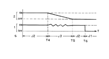
以下、この発明にかかる車両用灯具の実施形態(実施例)の1例を図面に基づいて詳細に説明する。なお、この実施形態によりこの発明が限定されるものではない。図3、図4において、縦軸は、第1半導体型光源の消灯・点灯状態および第2半導体型光源の消灯・点灯状態および出力診断手段の診断内容を示し、横軸は、時間を示す。図5において、縦軸は、ランプスイッチの操作状態および第1半導体型光源の消灯・点灯状態および第2半導体型光源の消灯・点灯状態および出力診断手段の診断内容を示し、横軸は、時間を示す。 Hereinafter, an example of an embodiment (example) of a vehicular lamp according to the present invention will be described in detail with reference to the drawings. In addition, this invention is not limited by this embodiment. 3 and 4, the vertical axis indicates the light extinction / lighting state of the first semiconductor light source, the light extinction / lighting state of the second semiconductor light source, and the diagnosis contents of the output diagnostic means, and the horizontal axis indicates time. In FIG. 5, the vertical axis indicates the lamp switch operation state, the first semiconductor light source extinguishing / lighting state, the second semiconductor light source extinguishing / lighting state, and the diagnostic contents of the output diagnostic means, and the horizontal axis indicates time Indicates.
(実施形態の構成の説明)
以下、この実施形態にかかる車両用灯具(車両用前照灯システム)の構成について説明する。前記車両用灯具は、この例では、車両用前照灯(ヘッドランプ)などであって、ヘッドランプユニットが車両の前部の左右両端部に搭載されている。前記車両用灯具は、第1半導体型光源1および第2半導体型光源2と、電流バイパス手段3と、バイパス制御手段4と、点灯回路5と、出力診断手段6と、ランプスイッチSと、制御装置7と、を備える。
(Description of Configuration of Embodiment)
Hereinafter, the configuration of the vehicle lamp (vehicle headlamp system) according to this embodiment will be described. In this example, the vehicular lamp is a vehicular headlamp (headlamp) or the like, and a headlamp unit is mounted on both left and right ends of the front portion of the vehicle. The vehicular lamp includes a first
(第1半導体型光源1および第2半導体型光源2の説明)
前記第1半導体型光源1および前記第2半導体型光源2は、外部からの電力供給により発光して、車両用灯具の光源として機能する。この例では、前記第1半導体型光源1は、車両用前照灯のすれ違い配光パターンの光源として機能する。また、前記第1半導体型光源1および前記第2半導体型光源2は、車両用前照灯の走行配光パターンの光源として機能する。
(Description of the first semiconductor-
The first semiconductor-
前記第1半導体型光源1および前記第2半導体型光源2は、電気的に直列に接続されている。前記第1半導体型光源1および前記第2半導体型光源2は、それぞれ、1個でも複数個でも良い。前記第1半導体型光源1および前記第2半導体型光源2は、この例では、たとえば、LED、OELまたはOLED(有機EL)、レーザーダイオードなどの自発光半導体型光源である。
The first
(電流バイパス手段3の説明)
前記電流バイパス手段3は、1個もしくは複数個の前記第2半導体型光源2と電気的に並列に接続されている。前記電流バイパス手段3は、1個もしくは複数個の前記第1半導体型光源1と電気的に直列に接続されている。前記電流バイパス手段3は、前記第2半導体型光源2に流れる電流を分流するものである。
(Description of current bypass means 3)
The current bypass means 3 is electrically connected in parallel with one or a plurality of the second
前記電流バイパス手段3は、メカニカルリレーのような物理接点を使用した場合においては、前記第2半導体型光源2に、電流を流す(接点開放状態)、または、電流を流さない(接点接続状態)の2つの動作の選択となる。また、前記電流バイパス手段3は、トランジスタなどの半導体接点を使用した場合においては、前記の2つの動作に加えて分流状態(前記第2半導体型光源3と前記電流バイパス手段3との双方に電流を流す)の動作を実現することができる。
In the case where a physical contact such as a mechanical relay is used, the current bypass means 3 allows a current to flow through the second semiconductor light source 2 (contact open state) or does not flow a current (contact connection state). These two operations are selected. In addition, in the case where a semiconductor contact such as a transistor is used, the current bypass means 3 is in a shunted state (current is supplied to both the second
(バイパス制御手段4の説明)
前記バイパス制御手段4は、点灯信号・消灯信号、故障検出ステータスなどの外部状況または内部状況に応じて、電流の分流状態を適宜に変化させるように、前記電流バイパス手段3を制御する。前記バイパス制御手段4は、前記の状況から適切な分流状態を決める判断部(図示せず)と、前記判断部の判断結果に応じて実際に前記電流バイパス手段3を動かす駆動部(図示せず)と、を備える。
(Description of bypass control means 4)
The bypass control unit 4 controls the
(点灯回路5の説明)
前記点灯回路5は、前記第1半導体型光源1および前記第2半導体型光源2から所望の光出力が得られるように、印加電圧・供給電流を適宜に調整する。前記点灯回路5、すなわち、車両用灯具における半導体型光源(半導体光源)の前記点灯回路5としては、DC−DCコンバータを用いた定電流回路、あるいは、抵抗などを用いた電流制限回路などを一般的に使用する。
(Description of lighting circuit 5)
The
(出力診断手段6の説明)
前記出力診断手段6は、前記点灯回路5からの出力電圧・出力電流を監視し、その出力電圧・出力電流が所定の範囲から外れた場合には異常が発生したと判断して、予め定められたフェイルセーフ処理を行う。フェイルセーフ処理としては、前記点灯回路5からの出力を停止する、あるいは、前記バイパス制御手段4を介して前記電流バイパス手段3の分流状態を変化させる。前記出力診断手段6は、フェイルセーフ処理と同時に、運転者に対して異常の発生を報知すべく、テルテールの点灯を指示する場合もある。
(Description of output diagnosis means 6)
The output diagnostic means 6 monitors the output voltage / output current from the
前記出力診断手段6の内容は、図3、図4、図5に示すように、停止状態J1と、通常状態J2と、切替中状態J3と、からなる。前記停止状態J1は、前記第1半導体型光源1および前記第2半導体型光源2がOFF状態(消灯状態)のときであって、前記出力診断手段6が診断を停止している状態にある。前記通常状態J2は、前記第1半導体型光源1がON状態(点灯状態)、あるいは、前記第1半導体型光源1および前記第2半導体型光源2がON状態(点灯状態)のときであって、前記出力診断手段6が通常の内容の診断をしている状態にある。前記切替中状態J3は、前記第2半導体型光源2がOFF状態(消灯状態)からON状態(点灯状態)に切り替わるまでの途中の状態、あるいは、前記第2半導体型光源2がON状態(点灯状態)からOFF状態(消灯状態)に切り替わるまでの途中の状態のときであって、前記出力診断手段6が通常の内容と異なる内容の診断をしている状態にある。
As shown in FIGS. 3, 4, and 5, the contents of the output diagnosis means 6 include a stopped state J1, a normal state J2, and a switching state J3. The stop state J1 is when the first semiconductor-
すなわち、前記電流バイパス手段3に流す電流の状態を変化させている間(前記切替状態J3)の前記出力診断手段6の内容は、前記電流バイパス手段3に流す電流の状態を変化させていない間(通常状態J2)の前記出力診断手段6の内容(通常の内容)に対して、変更されている。 That is, the contents of the output diagnostic means 6 while the state of the current flowing through the current bypass means 3 is changed (the switching state J3) is the same as when the state of the current flowing through the current bypass means 3 is not changed. The contents (normal contents) of the output diagnostic means 6 in (normal state J2) are changed.
前記出力診断手段6の変更される内容は、前記点灯回路5の出力異常の診断を停止させる内容である。すなわち、前記出力診断手段6は、前記切替中状態J3においては、前記停止状態J1と同様に、診断を停止している状態にある。また、前記出力診断手段6の変更される内容は、前記点灯回路5の出力異常を診断するための時間的閾値を変更させる内容である。すなわち、前記出力診断手段6は、前記通常状態J2における前記点灯回路5の出力異常診断時間(たとえば、約0.1秒)に対して、前記切替中状態J3における前記点灯回路5の出力異常診断時間(たとえば、約1秒)を長くする。時間を長くするには、サンプリング回数を増やす、あるいは、サンプリング周期を長くする。
The changed contents of the output diagnosis means 6 are contents for stopping the diagnosis of the output abnormality of the
前記出力診断手段6は、前記電流バイパス手段3に流す電流の状態変化が所定時間以上経過する場合において、前記電流バイパス手段3に流す電流の状態変化を制限する。すなわち、前記出力診断手段6は、図5に示すように、出力異常診断が完了(終了)する前に、前記ランプスイッチSを走行配光パターンの状態HIとすれ違い配光パターンの状態LOとに反復操作した場合において、出力異常診断ができなくなる場合がある。このために、前記出力診断手段6は、前記電流バイパス手段3に流す電流の状態変化が所定時間(たとえば、約数秒)以上経過する場合において、前記第2半導体型光源2を強制的にOFF状態(消灯状態)にする。
The
(ランプスイッチSの説明)
前記ランプスイッチSは、OFF位置、LO位置、HI位置、の3位置切替スイッチである。前記ランプスイッチSは、運転者の手動により切り替わるスイッチであり、かつ、車両の走行状況に応じて自動的に切り替わるスイッチである。
(Description of lamp switch S)
The lamp switch S is a three-position changeover switch of an OFF position, an LO position, and an HI position. The lamp switch S is a switch that is manually switched by the driver, and that is automatically switched according to the traveling state of the vehicle.
(制御装置7の説明)
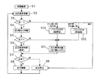
図6に示すように、前記制御装置(制御回路部やECU・電子制御ユニット)7には、前記点灯回路5、前記ランプスイッチSが接続されている。前記制御装置7は、前記ランプスイッチSの位置状況に応じて前記バイパス制御手段4および前記点灯回路5および前記出力診断手段6の作用を前記の通り制御する。すなわち、前記制御装置7は、図2に示すフローチャートの工程を順次処理する。
(Description of the control device 7)
As shown in FIG. 6, the
(実施形態の作用の説明)
この実施形態にかかる車両用灯具は、以上のごとき構成からなり、以下、その作用について説明する。
(Description of the operation of the embodiment)
The vehicular lamp according to this embodiment is configured as described above, and the operation thereof will be described below.
(図3の作用の説明)
まず、図3について説明する。時点T1までは、ランプスイッチSがOFF位置に位置するので、第1半導体型光源1および第2半導体型光源2がOFF状態にある。このとき、出力診断手段6は、停止状態J1にある。
(Description of the action of FIG. 3)
First, FIG. 3 will be described. Until time T1, since the lamp switch S is in the OFF position, the first semiconductor-
時点T1において、所定の点灯条件たとえばすれ違い配光パターン照射条件が成立する。すると、ランプスイッチSがLO位置に位置するので、点灯回路5が第1半導体型光源1に電流を流す。一方、バイパス制御手段4が電流バイパス手段3に第1半導体型光源1からの全部の電流を流して、第2半導体型光源2に電流を流さない。
At time T1, a predetermined lighting condition, for example, a passing light distribution pattern irradiation condition is satisfied. Then, since the lamp switch S is located at the LO position, the
時点T1から時点T2までの間は、第1半導体型光源1がON状態にあり、第2半導体型光源2がOFF状態にある。この結果、すれ違い配光パターンが照射される。このとき、出力診断手段6は、通常状態J2にあるので、点灯回路5の出力異常を通常の内容で診断する。
Between time T1 and time T2, the first
時点T2において、所定の点灯条件たとえば走行配光パターン照射条件が成立する。すると、ランプスイッチSがHI位置に位置するので、バイパス制御手段4が電流バイパス手段3に流れる電流を時間的傾きを持って遮断する。このために、第2半導体型光源2には電流が時間的傾きを持って流れる。これにより、第2半導体型光源2は、時点T2におけるOFF状態(0%点灯状態)から時点T3におけるON状態(100%点灯状態)まで時間的傾きを持って点灯(徐増点灯)する。
At time T2, a predetermined lighting condition, for example, a traveling light distribution pattern irradiation condition is satisfied. Then, since the lamp switch S is located at the HI position, the bypass control unit 4 blocks the current flowing through the
時点T2から時点T3までの間は、第1半導体型光源1がON状態にあり、第2半導体型光源2がOFF状態からON状態に変化している状態にある。この結果、すれ違い配光パターンから走行配光パターンに切り替わる状態にある。このとき、出力診断手段6は、切替中状態J3にあるので、点灯回路5の出力異常の診断内容を通常の診断内容に対して変更する。
Between time T2 and time T3, the first
すなわち、時点T2から時点T3までの間は、OFF状態からON状態に変化している状態にある第2半導体型光源2に流れる電流は、徐々に増加変化していて、また、ON状態にある第1半導体型光源1に流れる電流は、変動している。このために、出力診断手段6が通常の診断内容で点灯回路5の出力異常を診断した場合には、異常ではないのに異常であると誤診断する場合がある。
That is, during the period from the time T2 to the time T3, the current flowing through the second
すなわち、走行配光パターンからすれ違い配光パターンに切り替わるのに伴って、点灯回路5からの出力電圧・出力電流が変動するが、この変動幅が部品公差や温度特性などにより必ずしも一意に定められるものではない。このために、出力診断手段6の診断の基準設定によっては、「実際には正常である」にもかかわらずに「異常である」と誤診断する場合がある。
That is, as the traveling light distribution pattern is switched to the passing light distribution pattern, the output voltage and output current from the
そこで、出力診断手段6は、点灯回路5の出力異常の診断内容を通常の診断内容に対して変更して、前記の誤診断を防止する。診断内容の変更は、点灯回路5の出力異常の診断を停止させる、あるいは、点灯回路5の出力異常を診断するための時間的閾値を変更させるである。
Therefore, the output diagnostic means 6 changes the diagnostic content of the output abnormality of the
時点T3以降は、第1半導体型光源1および第2半導体型光源2がON状態にある。この結果、走行配光パターンが照射される。このとき、出力診断手段6は、通常状態J2にあるので、点灯回路5の出力異常を通常の内容で診断する。
After time T3, the first semiconductor-
(図4の作用の説明)
つぎは、図4について説明する。時点T4までは、第1半導体型光源1および第2半導体型光源2がON状態にある。この結果、走行配光パターンが照射される。このとき、出力診断手段6は、通常状態J2にあるので、点灯回路5の出力異常を通常の内容で診断する。
(Description of the action of FIG. 4)
Next, FIG. 4 will be described. Until the time T4, the first semiconductor-
時点T4において、所定の点灯条件たとえばすれ違い配光パターン照射条件が成立する。すると、ランプスイッチSがLO位置に位置するので、バイパス制御手段4が電流バイパス手段3に電流を時間的傾きを持って流す。このために、第2半導体型光源2に流れる電流が時間的傾きを持って遮断される。これにより、第2半導体型光源2は、時点T4におけるON状態(100%点灯状態)から時点T5におけるOFF状態(0%点灯状態)まで時間的傾きを持って消灯(徐減消灯)する。
At time T4, a predetermined lighting condition, for example, a passing light distribution pattern irradiation condition is satisfied. Then, since the lamp switch S is located at the LO position, the bypass control unit 4 causes the current to flow through the
時点T4から時点T5までの間は、第1半導体型光源1がON状態にあり、第2半導体型光源2がON状態からOFF状態に変化している状態にある。この結果、走行配光パターンからすれ違い配光パターンに切り替わる。このとき、出力診断手段6は、切替中状態J3にあるので、点灯回路5の出力異常の診断内容を通常の診断内容に対して変更する。
From time T4 to time T5, the first
すなわち、時点T4から時点T5までの間は、ON状態からOFF状態に変化している状態にある第2半導体型光源2に流れる電流は、徐々に減少変化していて、また、ON状態にある第1半導体型光源1に流れる電流は、変動している。このために、出力診断手段6が通常の診断内容で点灯回路5の出力異常を診断した場合には、異常ではないのに異常であると誤診断する場合がある。
That is, from time T4 to time T5, the current flowing through the second
すなわち、走行配光パターンからすれ違い配光パターンに切り替わるのに伴って、点灯回路5からの出力電圧・出力電流が変動するが、この変動幅が部品公差や温度特性などにより必ずしも一意に定められるものではない。このために、出力診断手段6の診断の基準設定によっては、「実際には正常である」にもかかわらずに「異常である」と誤診断する場合がある。
That is, as the traveling light distribution pattern is switched to the passing light distribution pattern, the output voltage and output current from the
そこで、出力診断手段6は、点灯回路5の出力異常の診断内容を通常の診断内容に対して変更して、前記の誤診断を防止する。診断内容の変更は、点灯回路5の出力異常の診断を停止させる、あるいは、点灯回路5の出力異常を診断するための時間的閾値を変更させるである。
Therefore, the output diagnostic means 6 changes the diagnostic content of the output abnormality of the
ここで、走行配光パターンからすれ違い配光パターンへの切替を瞬間的(時点T4から時点T5までの間の時間が短い)に行うと、第1半導体型光源1の両端には瞬間的に約2倍の電圧(第1半導体型光源1および第2半導体型光源2の両端電圧)が印加されて、第1半導体型光源1が破損する可能性がある。このために、走行配光パターンからすれ違い配光パターンに切り替える場合には、時間的傾き(フィードバック制御の応答時間<電流バイパス回路のインピーダンス低下時間)を持って、第1半導体型光源1に過大な負荷がかからないように制御されている。なお、時間的傾きの制御の他に、切替の直前において、点灯回路5側で出力電圧を十分に低下させる制御がある。
Here, when switching from the traveling light distribution pattern to the passing light distribution pattern is performed instantaneously (the time between the time T4 and the time T5 is short), the both ends of the first semiconductor-
時点T5から時点T6までの間は、第1半導体型光源1がON状態にあり、第2半導体型光源2がOFF状態にある。この結果、すれ違い配光パターンが照射される。このとき、出力診断手段6は、通常状態J2にあるので、点灯回路5の出力異常を通常の内容で診断する。
Between time T5 and time T6, the first
時点T6において、所定の点灯条件たとえばOFF条件が成立する。すると、ランプスイッチSがOFF位置に位置するので、点灯回路5が第1半導体型光源1および第2半導体型光源2に出力する電流を遮断する。このために、第1半導体型光源1および第2半導体型光源2がOFF状態にある。このとき、出力診断手段6は、停止状態J1にある。
At time T6, a predetermined lighting condition, for example, an OFF condition is satisfied. Then, since the lamp switch S is located at the OFF position, the
(図5の作用の説明)
さらに、図5について説明する。時点T7までは、ランプスイッチSがOFF位置に位置するので、第1半導体型光源1および第2半導体型光源2がOFF状態にある。このとき、出力診断手段6は、停止状態J1にある。
(Description of the action of FIG. 5)
Further, FIG. 5 will be described. Until time T7, since the lamp switch S is in the OFF position, the first semiconductor-
時点T7において、所定の点灯条件たとえばすれ違い配光パターン照射条件が成立する。すると、ランプスイッチSがLO位置に位置するので、点灯回路5が第1半導体型光源1に電流を流す。一方、バイパス制御手段4が電流バイパス手段3に第1半導体型光源1からの全部の電流を流して、第2半導体型光源2に電流を流さない。
At time T7, a predetermined lighting condition such as a passing light distribution pattern irradiation condition is satisfied. Then, since the lamp switch S is located at the LO position, the
時点T7から時点T8までの間は、第1半導体型光源1がON状態にあり、第2半導体型光源2がOFF状態にある。この結果、すれ違い配光パターンが照射される。このとき、出力診断手段6は、通常状態J2にあるので、点灯回路5の出力異常を通常の内容で診断する。
Between time T7 and time T8, the first
時点T8以降において、運転者が意図的にランプスイッチSをLO位置とHI位置と反復操作する(パッシング操作する)。すると、出力診断手段6は、切替中状態J3にあるので、点灯回路5の出力異常の診断内容を通常の診断内容に対して変更して診断する。ところが、出力異常診断が完了する前に、ランプスイッチSが切り替わると、出力診断手段6が診断途中の出力異常診断を中断してリセットし、新たに出力異常診断を開始する。このために、出力異常診断ができなくなる場合がある。
After the time point T8, the driver intentionally operates the lamp switch S repeatedly between the LO position and the HI position (passing operation). Then, since the output diagnosis means 6 is in the switching state J3, the diagnosis content of the output abnormality of the
そこで、制御装置7は、点灯回路5を介して、電流バイパス手段3に流す電流の状態変化が所定時間(たとえば、約数秒間、時点T8から時点T9までの間の時間)以上経過する場合において、すなわち、時点T9において、第2半導体型光源2を強制的にOFF状態にする。
Therefore, when the control device 7 changes the state of the current flowing through the current bypass means 3 through the
このために、時点T9以降においては、第1半導体型光源1のみがON状態にあり、すれ違い配光パターンが照射されることとなる。このとき、出力診断手段6は、通常状態J2にあるので、点灯回路5の出力異常を通常の内容で診断する。
For this reason, after time T9, only the first semiconductor-
(図2のフローチャートの説明)
以下、図2に示すフローチャートの工程の処理手順(作用)について説明する。まず、初期設定されて処理手順がスタートする(初期設定 S1)。ここで、前提条件として、ランプスイッチSがLO位置に位置していてすれ違い配光パターンが照射されているとする。
(Description of flowchart in FIG. 2)
Hereinafter, the processing procedure (action) of the process of the flowchart shown in FIG. 2 will be described. First, initialization is performed and the processing procedure starts (initial setting S1). Here, as a precondition, it is assumed that the lamp switch S is positioned at the LO position and the passing light distribution pattern is irradiated.
制御装置7は、点灯条件を判断する(点灯条件判断 S2)。すなわち、ランプスイッチSの位置が同一であるか否かを判断する(同一? S3)。 The control device 7 determines lighting conditions (lighting condition determination S2). That is, it is determined whether or not the positions of the lamp switches S are the same (same? S3).
ここで、ランプスイッチSの位置がLO位置の場合、すなわち、スイッチSの位置が同一の場合、制御装置7は、配光パターンの切替状態を判断する(切り替わり判断 S4)。すなわち、走行配光パターンからすれ違い配光パターンへの切替が完了したか否かを判断する(完了? S5)。 Here, when the position of the lamp switch S is the LO position, that is, when the position of the switch S is the same, the control device 7 determines the switching state of the light distribution pattern (switching determination S4). That is, it is determined whether or not switching from the traveling light distribution pattern to the passing light distribution pattern has been completed (complete? S5).
ここで、走行配光パターンからすれ違い配光パターンへの切替が完了している場合(図4中の時点T5を参照)、制御装置7を介して出力診断手段6は、点灯回路5の出力異常を通常状態J2における内容で診断する(出力異常判断(通常) S6)。すなわち、出力診断手段6は、点灯回路5の出力が正常であるか否か診断(判断)する(正常? S7)。
Here, when the switching from the traveling light distribution pattern to the passing light distribution pattern has been completed (see time point T5 in FIG. 4), the
ここで、点灯回路5の出力が正常である場合、制御装置7は、点灯回路5の出力を継続させ(出力継続 S8)、その後(S2)に戻る。前記の(S7)において、点灯回路5の出力が異常である場合、制御装置7は、点灯回路5の出力を停止させ(出力停止 S9)、その後(S2)に戻る。
Here, when the output of the
ここで、ランプスイッチSがLO位置からHI位置に切り替えられる(図3中の時点T2を参照)。すると、スイッチの位置が同一ではない。この場合、制御装置7は、配光パターンをすれ違い配光パターンから走行配光パターンに切り替えるために、点灯回路5およびバイパス制御手段4を介して、電流バイパス手段3の接点を開放状態とする(バイパスOFF(略開放) S10)。これにより、第2半導体型光源2に電流が時間的傾きを持って流れて、配光パターンが時間的傾きを持ってすれ違い配光パターンから走行配光パターンに切り替わる(図3中の時点T2から時点T3までの間を参照)。
Here, the lamp switch S is switched from the LO position to the HI position (see time point T2 in FIG. 3). Then, the positions of the switches are not the same. In this case, the control device 7 opens the contact of the current bypass means 3 via the
そして、制御装置7を介して出力診断手段6は、点灯回路5の出力異常を切替中状態J3における内容で診断する(出力異常判断(切り替わり中) S11)。すなわち、出力診断手段6は、点灯回路5の出力が正常であるか否か診断(判断)する(正常? S7)。
Then, the output diagnosis means 6 diagnoses the output abnormality of the
ここで、点灯回路5の出力が正常である場合、制御装置7は、点灯回路5の出力を継続させ(出力継続 S8)、その後(S2)に戻る。前記の(S7)において、点灯回路5の出力が異常である場合、制御装置7は、点灯回路5の出力を停止させ(出力停止 S9)、その後(S2)に戻る。
Here, when the output of the
ここで、ランプスイッチSがHI位置からLO位置に切り替えられる(図4中の時点T4を参照)。すると、スイッチの位置が同一ではない。この場合、制御装置7は、配光パターンを走行配光パターンからすれ違い配光パターンに切り替えるために、点灯回路5およびバイパス制御手段4を介して、電流バイパス手段3の接点を接続状態とする(バイパスON(略短絡) S12)。これにより、第2半導体型光源2への電流が時間的傾きを持って遮断されて、配光パターンが時間的傾きを持って走行配光パターンからすれ違い配光パターンに切り替わる(図3中の時点T2から時点T3までの間を参照)。
Here, the lamp switch S is switched from the HI position to the LO position (see time point T4 in FIG. 4). Then, the positions of the switches are not the same. In this case, in order to switch the light distribution pattern from the traveling light distribution pattern to the passing light distribution pattern, the control device 7 sets the contact point of the current bypass means 3 to the connected state via the
そして、制御装置7を介して出力診断手段6は、点灯回路5の出力異常を切替中状態J3における内容で診断する(出力異常判断(切り替わり中) S11)。すなわち、出力診断手段6は、点灯回路5の出力が正常であるか否か診断(判断)する(正常 S7)。
Then, the output diagnosis means 6 diagnoses the output abnormality of the
ここで、点灯回路5の出力が正常である場合、制御装置7は、点灯回路5の出力を継続させ(出力継続 S8)、その後(S2)に戻る。前記の(S7)において、点灯回路5の出力が異常である場合、制御装置7は、点灯回路5の出力を停止させ(出力停止 S9)、その後(S2)に戻る。
Here, when the output of the
ここで、ランプスイッチSがLO位置からOFFに切り替えられる(図4中の時点T6を参照)。すると、スイッチの位置が同一ではない。この場合、制御装置7は、すれ違い配光パターンを消すために、点灯回路5の出力を停止させ(出力停止 S9)、その後(S2)に戻る。
Here, the lamp switch S is switched from the LO position to OFF (see time point T6 in FIG. 4). Then, the positions of the switches are not the same. In this case, the control device 7 stops the output of the
ここで、前記の(S5)において、走行配光パターンからすれ違い配光パターンへの切替が完了していない場合(図4中の時点T4から時点T5までの間を参照)、または、すれ違い配光パターンから走行配光パターンへの切替が完了していない場合(図3中の時点T2から時点T3までの間を参照)は、前記の(S11)に進む。 Here, in the above (S5), when the switching from the traveling light distribution pattern to the passing light distribution pattern is not completed (refer to the period from time T4 to time T5 in FIG. 4), or the passing light distribution When the switching from the pattern to the traveling light distribution pattern is not completed (refer to the period from time T2 to time T3 in FIG. 3), the process proceeds to (S11).
ここで、運転者が意図的にランプスイッチSをLO位置とHI位置と反復操作する(パッシング操作する)。すると、出力診断手段6は、切替中状態J3にあるので、点灯回路5の出力異常の診断内容を通常の診断内容に対して変更して診断する(S11)。ところが、出力異常診断が完了する前に、ランプスイッチSが切り替わると、出力診断手段6が診断途中の出力異常診断を中断してリセットし、新たに出力異常診断を開始する。このために、出力異常診断ができなくなる場合がある。すなわち、前記の(S7)の工程が終了しない。
Here, the driver intentionally operates the lamp switch S repeatedly between the LO position and the HI position (passing operation). Then, since the output diagnosis means 6 is in the switching state J3, the diagnosis content of the output abnormality of the
このときは、制御装置7は、電流バイパス手段3に流す電流の状態変化が所定時間(たとえば、約数秒間、時点T8から時点T9までの間の時間)以上経過する場合において、すなわち、時点T9において、第2半導体型光源2を強制的にOFF状態にする。このために、すれ違い配光パターンが照射され、出力診断手段6による点灯回路5の出力異常診断を継続して行われる。
At this time, the control device 7 determines that the state change of the current flowing through the current bypass means 3 has elapsed for a predetermined time (for example, about several seconds, the time between the time T8 and the time T9), that is, the time T9. Then, the second
(実施形態の効果の説明)
この実施形態にかかる車両用灯具は、以上のごとき構成および作用からなり、以下、その効果について説明する。
(Explanation of effect of embodiment)
The vehicular lamp according to this embodiment is configured and operated as described above, and the effects thereof will be described below.
この実施形態にかかる車両用灯具は、電流バイパス手段3に流す電流の状態を変化させている間(すなわち、点灯回路5からの出力電圧・出力電流が変動している間)の出力診断手段6の出力診断内容を、電流バイパス手段3に流す電流の状態を変化させていない間(すなわち、点灯回路5からの出力電圧・出力電流が変動していない間)の出力診断手段6の出力診断内容に対して、変更させるものである。このために、電流バイパス手段3に流す電流の状態を変化させている間において、電流バイパス手段3に流す電流の状態を変化させていない間の出力診断手段6の出力診断内容による、誤診断を確実に防ぐことができる。すなわち、出力診断手段6による点灯回路5の出力異常診断を確実に行うことができる。
In the vehicle lamp according to this embodiment, the output diagnostic means 6 while the state of the current flowing through the current bypass means 3 is changed (that is, while the output voltage / output current from the
この実施形態にかかる車両用灯具は、出力診断手段6の変更される内容が、点灯回路5の出力異常の診断を停止させる内容である。このために、出力診断手段6による点灯回路5の出力異常診断をさらに確実に行うことができる。
In the vehicular lamp according to this embodiment, the changed contents of the output diagnostic means 6 are contents that stop the diagnosis of the output abnormality of the
この実施形態にかかる車両用灯具は、出力診断手段6の変更される内容が、点灯回路5の出力異常を診断するための時間的閾値を変更させる内容である。このために、出力診断手段6による点灯回路5の出力異常診断をさらに確実に行うことができる。しかも、出力診断手段6による点灯回路5の出力異常診断を継続して行われる。
In the vehicular lamp according to this embodiment, the contents to be changed by the output diagnosis means 6 are contents to change the temporal threshold for diagnosing the output abnormality of the
この実施形態にかかる車両用灯具は、電流バイパス手段3に流す電流の状態変化が所定時間以上経過する場合においては、電流バイパス手段3に流す電流の状態変化を制限する。このために、強制的に安定点灯状態に固定して、出力診断手段6による点灯回路5の出力異常診断を継続して行われるようにするものである。すなわち、この例では、ランプスイッチSのLO位置HI位置の切り替わり動作を制限して、ランプスイッチSをLO位置に固定することにより、点灯回路5の出力異常診断を正常に行われるようにするものである。
The vehicular lamp according to this embodiment limits the change in the state of the current flowing through the
(実施形態以外の例の説明)
この実施形態においては、すれ違い配光パターンを照射する場合、電流バイパス手段3の接点を接続状態として、第1半導体型光源1からの全電流を、電流バイパス手段3に流して、第2半導体型光源2に流れないようにしている。すなわち、第2半導体型光源2は、完全消灯の状態にある。ところが、この発明においては、第1半導体型光源1からの電流の一部を電流バイパス手段3に流して、第1半導体型光源1からの残りの電流を第2半導体型光源2に流すようにして、第2半導体型光源2を第1半導体型光源1よりも少ない電流で点灯させるようにしても良い。
(Description of example other than embodiment)
In this embodiment, when irradiating a passing light distribution pattern, the contact of the current bypass means 3 is set to the connected state, and the entire current from the first semiconductor-
1 第1半導体型光源
2 第2半導体型光源
3 電流バイパス手段
4 バイパス制御手段
5 点灯回路
6 出力診断手段
7 制御装置
J1 停止状態
J2 通常状態
J3 切替中状態
S ランプスイッチ
T1、T2、T3、T4、T5、T6、T7、T8、T9 時点
1 First semiconductor light source
2 Second semiconductor type
Claims (3)
2個以上の前記半導体型光源のうち1個以上の前記半導体型光源と並列に接続されている電流バイパス手段と、
前記電流バイパス手段に流す電流を制御するバイパス制御手段と、
前記半導体型光源に電力を供給する点灯回路と、
前記点灯回路の出力異常を診断する出力診断手段と、
を備え、
前記電流バイパス手段に流す電流の状態を変化させることで前記半導体型光源を点灯状態から消灯状態に切り替えている間の前記出力診断手段の内容は、前記電流バイパス手段に流す電流の状態を変化させていない間の前記出力診断手段の内容に対して、変更され、
前記電流バイパス手段に流す電流の状態変化が所定時間以上経過する場合は、前記電流バイパス手段に流す電流の状態変化を制限する、
ことを特徴とする車両用灯具。 Two or more semiconductor-type light sources connected in series;
Current bypass means connected in parallel with one or more of the semiconductor-type light sources out of two or more of the semiconductor-type light sources;
Bypass control means for controlling the current flowing through the current bypass means;
A lighting circuit for supplying power to the semiconductor light source;
Output diagnosis means for diagnosing an output abnormality of the lighting circuit;
With
The contents of the output diagnostic tool while switched to OFF state the semiconductor-type light source Rukoto change the state of the current flowing through the current bypass means from the lighting state, changes the state of the current flowing through the current bypass means The contents of the output diagnostic means are not changed while being changed ,
When the state change of the current flowing through the current bypass means elapses over a predetermined time, the state change of the current flowing through the current bypass means is limited,
A vehicular lamp characterized by the above.
ことを特徴とする請求項1に記載の車両用灯具。 The contents to be changed by the output diagnosis means are contents for stopping diagnosis of output abnormality of the lighting circuit.
The vehicular lamp according to claim 1.
ことを特徴とする請求項1に記載の車両用灯具。 The content to be changed by the output diagnostic means is content for changing a temporal threshold for diagnosing an output abnormality of the lighting circuit.
The vehicular lamp according to claim 1.
Priority Applications (1)
| Application Number | Priority Date | Filing Date | Title |
|---|---|---|---|
| JP2013090962A JP6209848B2 (en) | 2013-04-24 | 2013-04-24 | Vehicle lighting |
Applications Claiming Priority (1)
| Application Number | Priority Date | Filing Date | Title |
|---|---|---|---|
| JP2013090962A JP6209848B2 (en) | 2013-04-24 | 2013-04-24 | Vehicle lighting |
Publications (2)
| Publication Number | Publication Date |
|---|---|
| JP2014213663A JP2014213663A (en) | 2014-11-17 |
| JP6209848B2 true JP6209848B2 (en) | 2017-10-11 |
Family
ID=51939866
Family Applications (1)
| Application Number | Title | Priority Date | Filing Date |
|---|---|---|---|
| JP2013090962A Active JP6209848B2 (en) | 2013-04-24 | 2013-04-24 | Vehicle lighting |
Country Status (1)
| Country | Link |
|---|---|
| JP (1) | JP6209848B2 (en) |
Families Citing this family (1)
| Publication number | Priority date | Publication date | Assignee | Title |
|---|---|---|---|---|
| JPWO2022270414A1 (en) * | 2021-06-22 | 2022-12-29 |
Family Cites Families (3)
| Publication number | Priority date | Publication date | Assignee | Title |
|---|---|---|---|---|
| JP3661203B2 (en) * | 1994-08-29 | 2005-06-15 | 株式会社デンソー | Lamp short detection device |
| JP4983941B2 (en) * | 2010-03-02 | 2012-07-25 | 株式会社デンソー | Energization control device |
| JP5486388B2 (en) * | 2010-04-23 | 2014-05-07 | パナソニック株式会社 | Lighting device, headlight device using the same, and vehicle |
-
2013
- 2013-04-24 JP JP2013090962A patent/JP6209848B2/en active Active
Also Published As
| Publication number | Publication date |
|---|---|
| JP2014213663A (en) | 2014-11-17 |
Similar Documents
| Publication | Publication Date | Title |
|---|---|---|
| JP6199721B2 (en) | Vehicle lighting | |
| JPWO2017018128A1 (en) | Lighting circuit, vehicle lamp | |
| US11464100B2 (en) | Vehicle headlight system | |
| JP2018195448A (en) | Vehicle lamp | |
| JP5588184B2 (en) | LED lighting device, lighting device, and vehicle | |
| JP6209848B2 (en) | Vehicle lighting | |
| JP6751905B2 (en) | Lighting controls, lighting, and moving objects | |
| KR101156140B1 (en) | Apparatus for controlling a vehicle lamp | |
| US20170207050A1 (en) | Load drive apparatus | |
| JP7317238B2 (en) | circuit system | |
| JP2007302122A (en) | Vehicular lighting unit | |
| JP2014065454A (en) | Brake light drive control unit | |
| JP2010030376A (en) | Lighting fixture for vehicle | |
| JP2005153706A (en) | Lamp control device for vehicle | |
| JP2009280157A (en) | Vehicular headlamp device | |
| JP2013536124A (en) | Control device for controlling electric drive device of electric bicycle, and method of supplying power to electric load of electric bicycle | |
| JP5948202B2 (en) | Energization control circuit for vehicle turn lamp unit and energization control method for vehicle turn lamp unit | |
| US10272821B2 (en) | Control of at least one lighting means of a vehicle headlight depending on an electrical quantity providable on a vehicle headlight connection of a vehicle | |
| JP4933283B2 (en) | Meter dimmer for vehicle | |
| JP6216565B2 (en) | Lamp unit controller | |
| KR101349047B1 (en) | Led driving circuit for vehicles | |
| JP2014099400A (en) | Electrical connection device for head lamp | |
| WO2017168933A1 (en) | Light illumination control device | |
| KR20200069677A (en) | Apparatus for driving warning light and method for driving the same | |
| JP2018137148A (en) | Failure detection unit and vehicle illumination device |
Legal Events
| Date | Code | Title | Description |
|---|---|---|---|
| A621 | Written request for application examination |
Free format text: JAPANESE INTERMEDIATE CODE: A621 Effective date: 20160331 |
|
| A977 | Report on retrieval |
Free format text: JAPANESE INTERMEDIATE CODE: A971007 Effective date: 20170118 |
|
| A131 | Notification of reasons for refusal |
Free format text: JAPANESE INTERMEDIATE CODE: A131 Effective date: 20170124 |
|
| A521 | Request for written amendment filed |
Free format text: JAPANESE INTERMEDIATE CODE: A523 Effective date: 20170327 |
|
| TRDD | Decision of grant or rejection written | ||
| A01 | Written decision to grant a patent or to grant a registration (utility model) |
Free format text: JAPANESE INTERMEDIATE CODE: A01 Effective date: 20170815 |
|
| A61 | First payment of annual fees (during grant procedure) |
Free format text: JAPANESE INTERMEDIATE CODE: A61 Effective date: 20170828 |
|
| R150 | Certificate of patent or registration of utility model |
Ref document number: 6209848 Country of ref document: JP Free format text: JAPANESE INTERMEDIATE CODE: R150 |
|
| R250 | Receipt of annual fees |
Free format text: JAPANESE INTERMEDIATE CODE: R250 |
|
| R250 | Receipt of annual fees |
Free format text: JAPANESE INTERMEDIATE CODE: R250 |
|
| R250 | Receipt of annual fees |
Free format text: JAPANESE INTERMEDIATE CODE: R250 |
|
| R250 | Receipt of annual fees |
Free format text: JAPANESE INTERMEDIATE CODE: R250 |