WO2010016266A1 - Communication system, mobile station device, base station device, and communication method - Google Patents
Communication system, mobile station device, base station device, and communication method Download PDFInfo
- Publication number
- WO2010016266A1 WO2010016266A1 PCT/JP2009/003785 JP2009003785W WO2010016266A1 WO 2010016266 A1 WO2010016266 A1 WO 2010016266A1 JP 2009003785 W JP2009003785 W JP 2009003785W WO 2010016266 A1 WO2010016266 A1 WO 2010016266A1
- Authority
- WO
- WIPO (PCT)
- Prior art keywords
- signal
- bands
- unit
- channel
- station apparatus
- Prior art date
Links
Images


Classifications
-
- H—ELECTRICITY
- H04—ELECTRIC COMMUNICATION TECHNIQUE
- H04L—TRANSMISSION OF DIGITAL INFORMATION, e.g. TELEGRAPHIC COMMUNICATION
- H04L5/00—Arrangements affording multiple use of the transmission path
- H04L5/003—Arrangements for allocating sub-channels of the transmission path
- H04L5/0044—Arrangements for allocating sub-channels of the transmission path allocation of payload
-
- H—ELECTRICITY
- H04—ELECTRIC COMMUNICATION TECHNIQUE
- H04L—TRANSMISSION OF DIGITAL INFORMATION, e.g. TELEGRAPHIC COMMUNICATION
- H04L27/00—Modulated-carrier systems
- H04L27/26—Systems using multi-frequency codes
- H04L27/2601—Multicarrier modulation systems
- H04L27/2626—Arrangements specific to the transmitter only
- H04L27/2627—Modulators
- H04L27/2634—Inverse fast Fourier transform [IFFT] or inverse discrete Fourier transform [IDFT] modulators in combination with other circuits for modulation
- H04L27/2636—Inverse fast Fourier transform [IFFT] or inverse discrete Fourier transform [IDFT] modulators in combination with other circuits for modulation with FFT or DFT modulators, e.g. standard single-carrier frequency-division multiple access [SC-FDMA] transmitter or DFT spread orthogonal frequency division multiplexing [DFT-SOFDM]
-
- H—ELECTRICITY
- H04—ELECTRIC COMMUNICATION TECHNIQUE
- H04L—TRANSMISSION OF DIGITAL INFORMATION, e.g. TELEGRAPHIC COMMUNICATION
- H04L27/00—Modulated-carrier systems
- H04L27/26—Systems using multi-frequency codes
- H04L27/2601—Multicarrier modulation systems
- H04L27/2647—Arrangements specific to the receiver only
- H04L27/2649—Demodulators
- H04L27/265—Fourier transform demodulators, e.g. fast Fourier transform [FFT] or discrete Fourier transform [DFT] demodulators
-
- H—ELECTRICITY
- H04—ELECTRIC COMMUNICATION TECHNIQUE
- H04L—TRANSMISSION OF DIGITAL INFORMATION, e.g. TELEGRAPHIC COMMUNICATION
- H04L5/00—Arrangements affording multiple use of the transmission path
- H04L5/0091—Signaling for the administration of the divided path
- H04L5/0094—Indication of how sub-channels of the path are allocated
-
- H—ELECTRICITY
- H04—ELECTRIC COMMUNICATION TECHNIQUE
- H04W—WIRELESS COMMUNICATION NETWORKS
- H04W72/00—Local resource management
- H04W72/04—Wireless resource allocation
- H04W72/044—Wireless resource allocation based on the type of the allocated resource
- H04W72/0453—Resources in frequency domain, e.g. a carrier in FDMA
-
- H—ELECTRICITY
- H04—ELECTRIC COMMUNICATION TECHNIQUE
- H04L—TRANSMISSION OF DIGITAL INFORMATION, e.g. TELEGRAPHIC COMMUNICATION
- H04L27/00—Modulated-carrier systems
- H04L27/26—Systems using multi-frequency codes
- H04L27/2601—Multicarrier modulation systems
- H04L27/2647—Arrangements specific to the receiver only
- H04L27/2649—Demodulators
- H04L27/26524—Fast Fourier transform [FFT] or discrete Fourier transform [DFT] demodulators in combination with other circuits for demodulation
- H04L27/26526—Fast Fourier transform [FFT] or discrete Fourier transform [DFT] demodulators in combination with other circuits for demodulation with inverse FFT [IFFT] or inverse DFT [IDFT] demodulators, e.g. standard single-carrier frequency-division multiple access [SC-FDMA] receiver or DFT spread orthogonal frequency division multiplexing [DFT-SOFDM]
-
- H—ELECTRICITY
- H04—ELECTRIC COMMUNICATION TECHNIQUE
- H04W—WIRELESS COMMUNICATION NETWORKS
- H04W72/00—Local resource management
- H04W72/50—Allocation or scheduling criteria for wireless resources
- H04W72/54—Allocation or scheduling criteria for wireless resources based on quality criteria
- H04W72/542—Allocation or scheduling criteria for wireless resources based on quality criteria using measured or perceived quality
Definitions
- the present invention relates to a communication system, a mobile station apparatus, a base station apparatus, and a communication method.
- This application claims priority based on Japanese Patent Application No. 2008-203360 filed in Japan on August 6, 2008, the contents of which are incorporated herein by reference.
- 3GPP (3 rd Generation Partnership Project: Third Generation Partnership Project) is a project to carry out the study and creation of the specifications of the mobile phone system.
- 3GPP is based on a network developed from W-CDMA (Wideband-Code Division Multiple Access) and GSM (Global System for Mobile Communications).
- the W-CDMA system is standardized as a third generation cellular mobile communication system, and services are started sequentially.
- HSDPA High-Speed Downlink Packet Access
- EUTRA Evolved Universal Terrestrial Radio Access
- OFDMA Orthogonal Frequency Division Multiple Access
- OFDMA is a method for multiplexing users using subcarriers orthogonal to each other.
- AMCS adaptive modulation and coding scheme
- link adaptation adaptive radio link control
- AMCS is a wireless transmission parameter (AMC) such as an error correction method, an error correction coding rate, and a data modulation multi-value number, according to the channel quality of each mobile station apparatus, in order to efficiently perform high-speed packet data transmission. Mode).
- the channel quality of each mobile station apparatus is fed back to the base station apparatus using a CQI (Channel Quality Indicator).
- CQI Channel Quality Indicator
- FIG. 23 is a diagram for explaining a channel configuration used in a conventional wireless communication system. This channel configuration is used in a wireless communication system such as EUTRA (see Non-Patent Document 1).
- the wireless communication system shown in FIG. 23 includes a base station device 1000 and mobile station devices 2000a, 2000b, and 2000c.
- R01 indicates a communicable range of the base station apparatus 1000.
- Base station apparatus 1000 communicates with mobile station apparatuses that exist within range R01.
- a physical broadcast channel (PBCH: Physical Broadcast Channel), a physical downlink control channel (PDCCH: Physical Downlink Control Channel), and a physical downlink.
- PBCH Physical Broadcast Channel
- PDCCH Physical Downlink Control Channel
- PDSCH Physical Downlink Shared Channel
- PMCH Physical Multicast Channel
- PCFICH Physical Control Format Instruction Channel
- PHICH Physical Hybrid ARQ Indicator Channel
- the physical uplink shared channel (PUSCH: Physical Uplink Channel), the physical uplink control channel (PUCCH: Physical Uplink Control). Channel) and a physical random access channel (PRACH: Physical Random Access Channel).
- PUSCH Physical Uplink Channel
- PUCCH Physical Uplink Control
- PRACH Physical Random Access Channel
- FIG. 24 is a diagram illustrating an example of a band used in a conventional wireless communication system.
- the horizontal axis indicates the frequency
- the vertical axis indicates the carrier frequency.
- the carrier frequency is f11.
- the base station apparatus communicates with the mobile station apparatus using one continuous band W11 in the frequency direction.
- Such a band usage method is used in a general wireless communication system such as EUTRA.
- FIG. 25 is a diagram illustrating another example of a band used in a conventional wireless communication system.
- the horizontal axis indicates the frequency.
- a plurality of discontinuous bands W21 and W22 are used in the frequency direction (Non-Patent Document 2).
- aggregation using a plurality of bands that are discontinuous in the frequency direction is called aggregation.
- the base station device cannot appropriately allocate the resource block to the user who uses the mobile station device. Therefore, there has been a problem that the mobile station apparatus and the base station apparatus cannot perform efficient communication.
- the present invention has been made in view of the above circumstances, and an object of the present invention is to enable communication between a mobile station apparatus and a base station apparatus to be efficiently performed by appropriately allocating resource blocks by the base station apparatus.
- a system, a mobile station apparatus, a base station apparatus, and a communication method are provided.
- a communication system is a communication system including a base station device and a mobile station device, and the base station device is A signal transmission unit configured to transmit, to each of the plurality of bands, a signal in which data is arranged in a natural number of resource blocks located in the frequency direction and a signal including information specifying the plurality of bands to the mobile station device.
- the mobile station apparatus receives a signal including information for identifying the plurality of bands from any of the plurality of bands from the signal transmission unit, and based on the information for identifying the plurality of bands In each of the plurality of bands, a signal receiving unit that receives a signal in which data is arranged in natural number of resource blocks located in the frequency direction from the signal transmitting unit, and the signal receiving unit receives the signal. Data natural several resource blocks located in the frequency direction and a data extractor for extracting data from the arranged signals.
- the signal transmission unit transmits a signal in which data is arranged in natural subbands positioned in the frequency direction to the mobile station apparatus in each of a plurality of bands. You may send it.
- the signal transmission unit has a bandwidth of a subband in each of the plurality of bands according to the number of natural number of resource blocks located in the frequency direction. May be determined.
- the number of subbands in each of the plurality of bands is determined according to the number of natural number of resource blocks located in the frequency direction. You may do it.
- a communication system is a communication system including a base station device and a mobile station device, and data is stored in natural resource blocks located in the frequency direction in each of a plurality of bands. And a signal is transmitted from the base station apparatus to the mobile station apparatus.
- a mobile station apparatus is a mobile station apparatus that communicates with a base station apparatus, and includes a signal that includes information for identifying the plurality of bands via any of the plurality of bands. From the base station apparatus, and based on the information for specifying the plurality of bands, in each of the plurality of bands, a signal in which data is arranged in a natural number of resource blocks located in the frequency direction is transmitted to the base station A signal receiving unit for receiving data from the apparatus; and a data extracting unit for extracting data from a signal in which data is arranged in natural number of resource blocks located in a frequency direction received by the signal receiving unit.
- the mobile station apparatus includes a channel estimation unit that estimates channel quality in natural subbands in each of the plurality of bands
- the signal reception unit includes a plurality of bands.
- a signal including information for specifying the plurality of bands is received from the base station device via any of the plurality of bands, and the signal is positioned in the frequency direction in each of the plurality of bands based on the information for specifying the plurality of bands.
- a signal having data arranged in natural subbands is received from the base station apparatus, and the data extraction unit arranges data in natural subbands located in the frequency direction received by the signal receiving unit. Data may be extracted from the received signal.
- the signal including information for specifying the plurality of bands is inserted only in one of the plurality of bands, and the signal receiving unit is A signal including information specifying the plurality of bands may be detected and received.
- a base station apparatus is a base station apparatus that communicates with a mobile station apparatus, and in each of a plurality of bands, arranges data in natural resource blocks that are located in the frequency direction. And a signal transmission unit that transmits the signal including the information specifying the plurality of bands to the mobile station apparatus.
- the signal transmission unit moves the signal including information for specifying the plurality of bands via only one of the plurality of bands. You may transmit to a station apparatus.
- a communication method is a communication method using a base station device and a mobile station device, and the base station device is located in a frequency direction in each of a plurality of bands.
- a signal reception process for receiving a signal in which data is arranged in natural number of resource blocks located from the base station apparatus, and a natural number of resources located in the frequency direction received in the signal reception process Having the lock data is disposed in the signal and data extraction step of extracting data.
- the mobile station apparatus and the base station apparatus can perform efficient communication by appropriately allocating resource blocks by the base station apparatus.
- the wireless communication system of the present invention includes a base station device and a mobile station device.
- FIG. 1 (a) and 1 (b) are diagrams illustrating a physical resource block arrangement method according to an embodiment of the present invention.
- PRBs physical resource blocks
- FIG. 1A the vertical axis indicates the frequency.
- FIG. 1B the horizontal axis indicates time, and the vertical axis indicates frequency.
- a plurality of system bands (here, system band W1 and system band W2) are used when a base station apparatus and a mobile station apparatus communicate with each other.
- Each of system band W1 and system band W2 includes a plurality of subcarriers.
- FIG. 1B shows an example of a configuration of a subframe (subframe number 0) that is a transmission unit in OFDM (Orthogonal Frequency Division Multiplex), which is a kind of multicarrier communication scheme. Show.
- One subframe includes at least one slot.
- subframe # F0 includes two slots # S0 and # S1.
- the slot also includes at least one OFDM symbol.
- each slot # S0 and # S1 includes seven OFDM symbols.
- One slot is divided into a plurality of blocks in the frequency direction.
- One physical resource block (PRB) is configured with a predetermined number of subcarriers as a unit in the frequency direction.
- a unit composed of one subcarrier and one OFDM symbol is called a resource element. Modulation symbols and the like are mapped to each resource element by resource mapping processing in the physical layer.
- the physical resource block is an area obtained by dividing a subframe, which is a unit of transmission, into a lattice shape in two dimensions of frequency and time.
- PRB physical resource block
- a downlink reference signal A01 and a physical downlink channel A02 are arranged in the physical resource block (PRB).
- FIG. 1A and FIG. 1B show a case where the system uses two downlink bands, the system band W1 and the system band W2.
- 1 N is the system band W1 (N 1 is a natural number) arranged physical resource blocks (PRB) of two N in the system band W2 (N 2 is a natural number) by placing a physical resource block (PRB) of Yes.
- the system bandwidth allowed for the system is W1
- the system bandwidth is W2
- W PRB is set to a fixed value.
- N1 is set to a natural number that is (W 1 / W PRB ) or less
- N2 is set to a natural number that is (W 2 / W PRB ) or less.
- the physical resource block (PRB) is arranged in the N 1 W RPB band in the W1 band
- the physical resource block (PRB) is arranged in the N 2 W RPB band in the W2 band.
- W PRB is a parameter that can be set for each base station device (or each region) that is a transmitter
- W PRB is W1 / N 1 using a predetermined natural number N 1 or a predetermined natural number N 2 may be set as W2 / N 2 using a.
- W1 and W2 are used bandwidths in consideration of guard bands.
- FIGS. 2A and 2B are diagrams illustrating an example of propagation path characteristics in the physical resource block (PRB) when the physical resource block (PRB) arrangement illustrated in FIG. 1B is performed. It is. 2A and 2B, the vertical axis indicates the frequency.
- FIG. 2A shows propagation path characteristics on the frequency axis including the system band W1 and the system band W2.
- FIG. 2B shows propagation path characteristics in each physical resource block (PRB).
- the physical resource block (PRB) having the highest frequency among the physical resource blocks (PRB) allocated to the system band W1 and the physical resource block (PRB) having the lowest frequency among the physical resource blocks (PRB) allocated to the system band W2
- the propagation path characteristics become discontinuous between.
- physical resource blocks are arranged so as not to generate physical resource blocks (PRB) that straddle a plurality of system bands. Therefore, in any physical resource block (PRB), the propagation path characteristics are continuous inside the physical resource block (PRB).
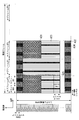
- FIG. 3 is a diagram illustrating an example of a configuration of a physical resource block (PRB) used in the embodiment of the present invention.
- PRB physical resource block
- the horizontal axis indicates time, and the vertical axis indicates frequency.
- Subframe # F0 includes slot # S0 and slot # S1.
- the band of one physical resource block (PRB) is W PRB .
- the downlink reference signal A01 is arranged in the black area, and the physical channel A02 is arranged in the white area.
- the downlink reference signal A01 is a known signal between the base station apparatus 100 and the mobile station apparatus 200.
- the downlink reference signal A01 is used for propagation path estimation and reception quality (reception power, reception SNR (Signal to Noise power Ratio), etc.) measurement and the like.
- propagation path estimation values in each resource element in the physical channel are required.
- the channel estimation value in the resource element is calculated using the channel estimation value in the reference signal. For example, a method using the continuity of propagation path characteristics such as the following (1a) to (3a) is used.
- the propagation path estimated value in the reference signal is used as it is as the propagation path estimated value in each resource element in the physical channel.
- the channel estimation value in each resource element in the physical channel is calculated by interpolating the channel estimation value in the reference signal.
- MMSE Minimum Mean Square Error
- the mobile station device 200 uses the reference signal to receive the physical resource block (PRB) reception quality. Is measured, the measurement result is processed, and the result is fed back to the base station apparatus 100, whereby scheduling and transmission parameters are set according to the propagation path characteristics. At this time, the accuracy of the reception quality of the physical resource block (PRB) is greatly affected by the dispersion (variation) of propagation path characteristics in the physical resource block (PRB).
- the physical resource block (PRB) is arranged so as not to generate a physical resource block (PRB) that straddles a plurality of system bands. Therefore, in any physical resource block (PRB), propagation path characteristics are continuous inside the physical resource block (PRB), and dispersion is relatively small, so that the accuracy of reception quality measurement can be maintained.
- the physical resource blocks (PRB) used in the embodiment of the present invention have a natural number of physical resource blocks (PRB) arranged on the frequency axis in each of a plurality of bands. Thereby, it is possible to prevent the accuracy of propagation path estimation and reception quality measurement from deteriorating.
- This wireless communication system includes a base station device 100 (FIG. 10) and a mobile station device 200 (FIG. 11).
- FIG. 4 is a diagram illustrating an example of a band used in the communication system according to the first embodiment of the present invention.
- the horizontal axis indicates the frequency.
- a base station apparatus 100 and a mobile station apparatus are used using a system band W1 and a system band W2 having a carrier frequency f1, as shown in FIG. 200 communicates.
- Base station apparatus 100 transmits a signal to mobile station apparatus 200 using system band W1 and system band W2 as one carrier.
- signals may be transmitted to the mobile station apparatus 200 using different carriers.
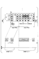
- FIGS. 5A and 5B are diagrams illustrating an example of a subframe configuration used in the first embodiment of the present invention.
- shaft has shown the frequency.
- the horizontal axis indicates time, and the vertical axis indicates frequency.
- a plurality of bands here, the system band W1 and the system band W2
- Each of system band W1 and system band W2 includes a plurality of subcarriers.
- subframe # F0 includes slot # S0 and slot # S1.
- Each of slot # S0 and slot # S1 includes 7 OFDM symbols.
- the bandwidth W PRB physical resource block (PRB) is contained two N.
- a downlink reference signal A01 and a physical downlink channel A02 are arranged in the N 2 W PRB band.
- the bandwidth W PRB physical resource block (PRB) is included one N.
- a downlink reference signal A01, a physical downlink channel A02, a physical downlink synchronization signal A03, and a physical broadcast channel (PBCH) A04 are arranged.
- a physical downlink synchronization signal A03 (synchronization channel) that is a signal for synchronization and a physical broadcast channel A04 that is a channel including broadcast information are inserted into one of the system bands (here, the system band W1).
- the mobile station apparatus 200 searches for the physical downlink synchronization signal A03 and establishes synchronization, and acquires information in the physical broadcast channel A04.
- the information in the physical broadcast channel A04 includes information indicating the system band (information regarding the area of the aggregation resource including the system band W2).
- the mobile station apparatus 200 receives the system band W1 and the system band W2 from the base station apparatus 100 using this information.
- the system band W1 N 1 amino placing the N 2 pieces of physical resource blocks (PRB) in the system band W2.
- PRB physical resource block
- the propagation path characteristics are continuous inside the physical resource block (PRB). For this reason, it is possible to prevent the accuracy of channel estimation and reception quality measurement from deteriorating.
- the embodiment of the present invention is applied to an EUTRA system using a plurality of system bands based on the EUTRA system will be described.
- the channel configuration used in the communication system according to the first embodiment of the present invention will be described.
- FIG. 6 is a diagram showing a configuration of a downlink channel used in the communication system according to the first embodiment of the present invention.
- FIG. 7 is a diagram showing a configuration of an uplink channel used in the communication system according to the first embodiment of the present invention.
- the downlink channel shown in FIG. 6 and the uplink channel shown in FIG. 7 are each composed of a logical channel, a transport channel, and a physical channel.
- the logical channel defines the type of data transmission service that is transmitted and received in a medium access control (MAC) layer.
- the transport channel defines what characteristics the data transmitted over the radio interface has and how it is transmitted.
- a physical channel is a physical channel that carries a transport channel.
- the downlink logical channel includes a broadcast control channel (BCCH), a paging control channel (PCCH), a common control channel (CCCH), and a dedicated control channel (DCCH: Dedicated Control Channel). ), A dedicated traffic channel (DTCH: Dedicated Traffic Channel), a multicast control channel (MCCH: Multicast Control Channel), and a multicast traffic channel (MTCH: Multicast Traffic Channel).
- the uplink logical channels include a common control channel (CCCH), a dedicated control channel (DCCH), and a dedicated traffic channel (DTCH).
- the downlink transport channels include a broadcast channel (BCH), a paging channel (PCH), a downlink shared channel (DL-SCH), and a multicast channel (MCH). included.
- the uplink transport channels include an uplink shared channel (UL-SCH: Uplink Shared Channel) and a random access channel (RACH: Random Access Channel).
- the downlink physical channel includes a physical broadcast channel (PBCH: Physical Broadcast Channel), a physical downlink control channel (PDCCH: Physical Downlink Control Channel), a physical downlink shared channel (PDSCH: Physical Downlink Multilink Channel). (PMCH: Physical Multicast Channel), Physical Control Format Indication Channel (PCFICH: Physical Control Format Channel), Physical Hybrid Automatic Repeat Request Indication Channel (PHICH: Physical Hybrid ARQ Indicator) It is included.
- the uplink physical channel includes a physical uplink shared channel (PUSCH), a physical random access channel (PRACH), and a physical uplink control channel (PUCCH: physical uplink). It is. These channels are transmitted and received between the base station apparatus 100 and the mobile station apparatus 200 as shown in FIG.
- the broadcast control channel is a downlink channel used for broadcasting system control information.
- the paging control channel is a downlink channel used for transmitting paging information, and is used when the network does not know the cell position of the mobile station apparatus.
- the common control channel is a channel used for transmitting control information between the mobile station apparatus and the network, and the mobile station apparatus does not have a radio resource control (RRC) connection with the network. Used by.
- the dedicated control channel is a one-to-one (point-to-point) bidirectional channel, and is a channel used to transmit individual control information between the mobile station apparatus 200 and the network.
- the dedicated control channel is used by a mobile station apparatus having an RRC connection.
- the dedicated traffic channel is a one-to-one bidirectional channel, is a channel dedicated to one mobile station apparatus, and is used for transferring user information (unicast data).
- the multicast control channel is a downlink channel used to transmit MBMS (Multimedia Broadcast Service) control information from the network to the mobile station apparatus 200 in a point-to-multipoint manner. It is. This is used for MBMS services that provide one-to-many services.
- MBMS Multimedia Broadcast Service
- MBMS service transmission methods include single-cell point-to-multipoint (SCPTM) transmission, and multimedia broadcast multicast service single frequency network (MBSFN) transmission and single frequency network transmission (MBSFN).
- SCPTM single-cell point-to-multipoint
- MBSFN multimedia broadcast multicast service single frequency network
- MBSFN Transmission is a simultaneous transmission technique for transmitting identifiable waveforms (signals) from a plurality of cells simultaneously.
- SCPTM transmission is a method of transmitting an MBMS service by one base station apparatus.
- the multicast control channel is used for one or more multicast traffic channels (MTCH).
- the multicast traffic channel is a downlink channel used for transmitting point-to-multipoint traffic data (MBMS transmission data) from the network to the mobile station apparatus. Note that the multicast control channel (MCCH) and the multicast traffic channel (MTCH) are used only by the mobile station apparatus that receives MBMS.
- the broadcast channel (BCH) is broadcast to the entire cell in a fixed and predefined transmission format.
- the downlink shared channel (DL-SCH) supports HARQ (Hybrid Automatic Repeat Request), dynamic adaptive radio link control, discontinuous reception (DRX), and MBMS transmission. Need to be done. Further, in the downlink shared channel (DL-SCH), beamforming can be used, and dynamic resource allocation and quasi-static resource allocation are supported.
- the paging channel (PCH) supports DRX and needs to be broadcast to the entire cell.
- the paging channel (PCH) is mapped to a physical resource that is dynamically used for a traffic channel and other control channels, that is, a physical downlink shared channel (PDSCH).
- PDSCH physical downlink shared channel
- the multicast channel needs to be broadcast to the entire cell.
- quasi-static resource allocation such as MBSFN (MBMS Single Frequency Network) combining (Combining) of MBMS transmission from multiple cells and time frames using extended cyclic prefix (CP) Is supported.
- MBSFN MBMS Single Frequency Network
- CP extended cyclic prefix
- the uplink shared channel (UL-SCH) supports HARQ and dynamic adaptive radio link control.
- beam forming can be used in the uplink shared channel (UL-SCH). Dynamic resource allocation and semi-static resource allocation are supported.
- the random access channel (RACH) transmits limited control information and has a collision risk.
- the physical broadcast channel maps the broadcast channel (BCH) at intervals of 40 milliseconds.
- the timing of 40 milliseconds is blind detection (blind detection). That is, it is not necessary to perform explicit signaling for timing presentation.
- PBCH physical broadcast channel
- a subframe including a physical broadcast channel (PBCH) can be decoded only by the subframe. That is, self-decoding is possible.
- the physical downlink control channel is downlink shared channel (PDSCH) resource allocation, hybrid automatic repeat request (HARQ) information for downlink data, and uplink that is physical uplink shared channel (PUSCH) resource allocation.
- PDSCH downlink shared channel
- HARQ hybrid automatic repeat request
- PUSCH physical uplink shared channel
- the physical downlink shared channel is a channel used for transmitting downlink data or paging information.
- the physical multicast channel is a channel used for transmitting the multicast channel (MCH), and a downlink reference signal, an uplink reference signal, and a physical downlink synchronization signal are separately arranged.
- the physical uplink shared channel is a channel mainly used for transmitting uplink data (UL-SCH).
- the channel feedback report CQI, PMI, RI
- the HARQ acknowledgment ACK: Acknowledgement
- NACK Negative Acknowledgment
- the physical random access channel is a channel used for transmitting a random access preamble and has a guard time.
- the physical uplink control channel (PUCCH) is a channel used to transmit a channel feedback report (CFR), a scheduling request (SR: Scheduling Request), HARQ for downlink transmission, an acknowledgment / negative response, and the like.
- the physical control format indication channel is a channel used to notify the mobile station apparatus of the number of OFDM symbols used for the physical downlink control channel (PDCCH), and is transmitted in each subframe.
- the physical hybrid automatic repeat request instruction channel is a channel used for transmitting HARQ ACK / NACK for uplink transmission.
- mapping between the transport channel and the physical channel is performed as follows.
- the broadcast channel (BCH) is mapped to the physical broadcast channel (PBCH).
- the multicast channel (MCH) is mapped to the physical multicast channel (PMCH).
- the paging channel (PCH) and the downlink shared channel (DL-SCH) are mapped to the physical downlink shared channel (PDSCH).
- the physical downlink control channel (PDCCH), the physical hybrid automatic repeat request instruction channel (PHICH), and the physical control format instruction channel (PCFICH) are used alone.
- the transport channel and the physical channel are mapped as follows.
- the uplink shared channel (UL-SCH) is mapped to the physical uplink shared channel (PUSCH).
- the random access channel (RACH) is mapped to the physical random access channel (PRACH).
- the physical uplink control channel (PUCCH) is used as a physical channel alone.
- mapping between logical channels and transport channels is performed as follows.
- the paging control channel (PCCH) is mapped to the downlink shared channel (DL-SCH).
- the broadcast control channel (BCCH) is mapped to the broadcast channel (BCH) and the downlink shared channel (DL-SCH).
- the common control channel (CCCH), dedicated control channel (DCCH), and dedicated traffic channel (DTCH) are mapped to the downlink shared channel (DL-SCH).
- the multicast control channel (MCCH) is mapped to the downlink shared channel (DL-SCH) and the multicast channel (MCH).
- the multicast traffic channel (MTCH) is mapped to the downlink shared channel (DL-SCH) and the multicast channel (MCH).
- mapping from the multicast control channel (MCCH) and the multicast traffic channel (MTCH) to the multicast channel (MCH) is performed at the time of MBSFN transmission.
- this mapping is mapped to the downlink shared channel (DL-SCH).
- the logical channel and the transport channel are mapped as follows.
- the common control channel (CCCH), the dedicated control channel (DCCH), and the dedicated traffic channel (DTCH) are mapped to the uplink shared channel (UL-SCH).
- the random access channel (RACH) is not mapped to the logical channel.
- FIG. 8 is a diagram illustrating a frame configuration used in the downlink of the wireless communication system according to the first embodiment of the present invention.
- FIG. 9 is a diagram illustrating a frame configuration used in the uplink of the wireless communication system according to the first embodiment of the present invention. 8 and 9, the horizontal axis indicates time, and the vertical axis indicates frequency.
- a radio frame identified by a system frame number (SFN) is composed of 10 milliseconds (10 ms).
- One subframe is composed of 1 millisecond (1 ms).
- the radio frame includes ten subframes # F0 to # F9.
- the radio frame used in the downlink includes a physical control format indication channel (PCFICH) A11, a physical hybrid automatic repeat request indication channel (PHICH) A12, a physical downlink control channel (PDCCH) A13, A link synchronization signal A14, a physical broadcast channel (PBCH) A15, a physical downlink shared channel (PDSCH) / physical multicast channel (PMCH) A16, and a downlink reference signal A17 are arranged.
- PCFICH physical control format indication channel
- PHICH physical hybrid automatic repeat request indication channel
- PDCCH physical downlink control channel
- a link synchronization signal A14 a physical broadcast channel (PBCH) A15
- PBCH physical broadcast channel
- PDSCH physical downlink shared channel
- PMCH physical multicast channel
- the radio frame used in the uplink includes a physical random access channel (PRACH) A21, a physical uplink control channel (PUCCH) A22, a physical uplink shared channel (PUSCH) A23, and an uplink demodulation reference.
- PRACH physical random access channel
- PUCCH physical uplink control channel
- PUSCH physical uplink shared channel
- a signal A24 and an uplink measurement reference signal A25 are arranged.
- One subframe (for example, subframe # F0) is divided into two slots # S0 and # S2.
- the downlink slot is composed of 7 OFDM symbols (see FIG. 8), and the uplink slot is 7 SC-FDMA (Single Carrier-Frequency). It is composed of (Division Multiple Access) symbols (see FIG. 9).
- an extended CP also referred to as long CP or extended CP
- the downlink slot is composed of 6 OFDM symbols
- the uplink slot is composed of 6 SC-FDMA symbols. Is done.
- One slot is divided into a plurality of blocks in the frequency direction.
- One physical resource block (PRB) is configured with 12 subcarriers of 15 kHz as units in the frequency direction.
- the number of physical resource blocks (PRBs) is supported from 6 to 110 depending on the system bandwidth.
- Downlink and uplink resource allocation is performed in subframe units in the time direction and in physical resource block (PRB) units in the frequency direction. That is, two slots in a subframe are allocated with one resource allocation signal.
- a unit composed of a subcarrier and an OFDM symbol or a subcarrier and an SC-FDMA symbol is called a resource element.
- a modulation symbol or the like is mapped to each resource element in the resource mapping process in the physical layer.
- cyclic redundancy check (CRC) is added to the physical downlink shared channel (PDSCH), channel coding (transmission path coding), physical layer HARQ Processing, channel interleaving, scrambling, modulation (QPSK (Quadrature Phase Shift Keying), 16QAM (Quadrature Amplitude Modulation), 64QAM), layer mapping, precoding, antenna mapping Mapping is performed.
- CRC cyclic redundancy check
- a 24-bit cyclic redundancy check is assigned to the physical uplink shared channel (PUSCH), channel coding (transmission path coding), physical layer HARQ processing, Scrambling, modulation (QPSK, 16QAM, 64QAM), resource mapping, antenna mapping, etc. are performed.
- CRC cyclic redundancy check
- the physical downlink control channel (PDCCH), the physical hybrid automatic repeat request indication channel (PHICH), and the physical control format indication channel (PCFICH) are arranged below the first 3 OFDM symbols.
- a transport format, resource allocation, and HARQ information for the downlink shared channel (DL-SCH) and the paging channel (PCH) are transmitted.
- the transport format defines a modulation scheme, a coding scheme, a transport block size, and the like.
- the physical downlink control channel transmits transport format (modulation scheme, coding scheme, transport block size, etc.), resource allocation, and HARQ information for the uplink shared channel (UL-SCH). Is done.
- transport format modulation scheme, coding scheme, transport block size, etc.
- resource allocation resource allocation
- HARQ information for the uplink shared channel (UL-SCH). Is done.
- a plurality of physical downlink control channels (PDCCH) are supported, and the mobile station apparatus 200 monitors a set of physical downlink control channels (PDCCH).
- the physical downlink shared channel (PDSCH) allocated by the physical downlink control channel (PDCCH) is mapped to the same subframe as the physical downlink control channel (PDCCH).
- the physical uplink shared channel (PUSCH) allocated by the physical downlink control channel (PDCCH) is mapped to a subframe at a predetermined position. For example, when the downlink subframe number of the physical downlink control channel (PDCCH) is N, it is mapped to the N + 4th uplink subframe.
- the mobile station apparatus is specified using 16-bit MAC layer identification information (MAC ID). That is, this 16-bit MAC layer identification information (MAC ID) is included in the physical downlink control channel (PDCCH).
- the downlink reference signal (downlink pilot channel) used for downlink state measurement and downlink data demodulation is arranged in the first, second, and third from the back of each slot.
- an uplink demodulation reference signal (demodulation pilot signal (DRS)) used for demodulation of the physical uplink shared channel (PUSCH) is transmitted in the fourth SC-FDMA symbol of each slot.
- an uplink measurement reference signal (scheduling reference signal (SRS)) used for uplink state measurement is transmitted in the first SC-FDMA symbol of the subframe.
- the reference signal for demodulation of the uplink control channel (PUCCH) is defined for each uplink control channel format, and the third, fourth and fifth of each slot, or the second and sixth SC-FDMA symbols of each slot Sent by.
- the physical broadcast channel (PBCH) and the downlink synchronization signal are arranged in a band corresponding to the center 6 physical resource blocks in the system band.
- the physical downlink synchronization signal is transmitted in the sixth and seventh OFDM symbols of each slot of the first (subframe # F0) and fifth (subframe # F4) subframes.
- the physical broadcast channel (PBCH) is the 4th, 5th OFDM symbol of the 1st slot (slot # S0) of the 1st (subframe # 0) and 1 of the 2nd slot (slot # S1).
- the second and second OFDM symbols are transmitted.
- the random access channel is configured with a bandwidth of six physical resource blocks in the frequency direction and one subframe in the time direction.
- Request from mobile station device to base station device for various reasons uplink resource request, uplink synchronization request, downlink data transmission resumption request, handover request, connection setting request, reconnection request, MBMS service request, etc.) Sent to do.
- the uplink control channel (PUCCH) is arranged at both ends of the system band and is configured in units of physical resource blocks. Frequency hopping is performed so that both ends of the system band are alternately used between slots.
- FIG. 10 is a schematic block diagram showing the configuration of the base station device 100 according to the first embodiment of the present invention.
- the base station apparatus 100 includes a data control unit 101a, an OFDM modulation unit 102a, a radio unit 103a, a scheduling unit 104, a channel estimation unit 105, a DFT-S-OFDM (DFT-Spread-OFDM) demodulation unit 106, a data extraction unit 107, An upper layer 108 and an antenna part A1 are provided.
- Radio section 103a, scheduling section 104, channel estimation section 105, DFT-S-OFDM demodulation section 106, data extraction section 107, upper layer 108, and antenna section A1 constitute a reception section.
- the data control unit 101a, the OFDM modulation unit 102a, the radio unit 103a, the scheduling unit 104, the upper layer 108, and the antenna unit A1 constitute a transmission unit.
- the radio unit 103a, the channel estimation unit 105, the DFT-S-OFDM demodulation unit 106, and the data extraction unit 107 perform uplink physical layer processing.
- the data control unit 101a, the OFDM modulation unit 102a, and the radio unit 103a perform downlink physical layer processing.
- the data control unit 101 a acquires the transport channel and scheduling information from the scheduling unit 104. Signals and channels generated in the transport channel and the physical layer are mapped to physical channels based on the scheduling information input from the scheduling unit 104. Each piece of data mapped as described above is output to OFDM modulation section 102a.
- the OFDM modulation unit 102a receives scheduling information (downlink physical resource block (PRB) allocation information (for example, physical resource block position such as frequency, time, etc.) input from the scheduling unit 104. Information) and a modulation scheme and a coding scheme corresponding to each downlink physical resource block (PRB) (including 16QAM modulation, 2/3 coding rate, etc.), encoding, data modulation, input signal Performs OFDM signal processing such as serial / parallel conversion, IFFT (Inverse Fast Fourier Transform) processing, cyclic prefix (CP) insertion, and filtering to generate an OFDM signal and wirelessly And outputs it to the 103a.
- scheduling information downlink physical resource block (PRB) allocation information (for example, physical resource block position such as frequency, time, etc.) input from the scheduling unit 104. Information) and a modulation scheme and a coding scheme corresponding to each downlink physical resource block (PRB) (including 16QAM modulation, 2/3 coding rate, etc.), encoding, data
- the radio unit 103a generates a radio signal by up-converting the modulation data input from the OFDM modulation unit 102a to a radio frequency, and transmits the radio signal to the mobile station device 200 (see FIG. 11 described later) via the antenna unit A1. . Also, the radio section 103a receives an uplink radio signal from the mobile station apparatus 200 via the antenna section A1, down-converts it into a baseband signal, and converts the received data to the channel estimation section 105 and the DFT-S- Output to the OFDM demodulator 106.
- the scheduling unit 104 performs processing in a medium access control (MAC) layer.
- the scheduling unit 104 performs mapping between logical channels and transport channels, downlink and uplink scheduling (HARQ processing, selection of transport format, etc.) and the like.
- the scheduling unit 104 receives uplink feedback information (downlink channel feedback information (channel state information (channel quality, number of streams, precoding information, etc.)) received from the mobile station apparatus 200, ACK / NACK feedback information for downlink data), information on downlink physical resource blocks (PRB) that can be used by each mobile station apparatus 200, buffer status, scheduling information input from higher layer 108, etc.
- uplink feedback information downlink channel feedback information (channel state information (channel quality, number of streams, precoding information, etc.)
- PRB downlink physical resource blocks
- a downlink transport format (transmission form) for modulating data (physical resource block (PRB) allocation, modulation scheme, encoding scheme, etc.) selection processing and retransmission control in HARQ are performed.
- the scheduling information used for the downlink scheduling is output to the data control unit 101a.
- the scheduling unit 104 estimates the uplink channel state (wireless channel state) output from the channel estimation unit 105, the resource allocation request from the mobile station device 200, and each mobile station device 200.
- Uplink transport format transmission form
- PRB physical resource block
- PRB physical resource block assignment
- modulation scheme modulation scheme
- encoding scheme modulation scheme, encoding scheme, and the like
- the scheduling unit 104 maps the downlink logical channel input from the higher layer 108 to the transport channel, and outputs it to the data control unit 101a.
- the scheduling unit 104 processes the control data and the transport channel acquired from the uplink input from the data extraction unit 107 as necessary, maps them to the uplink logical channel, and outputs them to the upper layer 108. To do.
- the channel estimation unit 105 estimates an uplink channel state from an uplink demodulation reference signal (DRS: Demodulation Reference Signal) for demodulation of uplink data, and the estimation result is used as a DFT-S-OFDM demodulation unit 106. Output to.
- DRS Demodulation Reference Signal
- an uplink channel state is estimated from an uplink measurement reference signal (SRS: Sounding Reference Signal), and the estimation result is output to the scheduling section 104.
- SRS Sounding Reference Signal
- the uplink communication scheme is assumed to be a single carrier scheme such as DFT-S-OFDM, but a multicarrier scheme such as the OFDM scheme may be used.
- the DFT-S-OFDM demodulation unit 106 performs DFT (Discrete Fourier Transform: Discrete Fourier Transform) on the modulation data input from the radio unit 103 a based on the uplink channel state estimation result input from the channel estimation unit 105. ) Performs DFT-S-OFDM signal processing such as conversion, subcarrier mapping, IFFT conversion, filtering, etc., performs demodulation processing, and outputs the result to the data extraction unit 107.
- DFT Discrete Fourier Transform: Discrete Fourier Transform
- the data extraction unit 107 confirms whether the data input from the DFT-S-OFDM demodulation unit 106 is correct, and outputs a confirmation result (positive signal ACK / negative signal NACK) to the scheduling unit 104. Further, the data extraction unit 107 separates the data input from the DFT-S-OFDM demodulation unit 106 into a transport channel and physical layer control data, and outputs the separated data to the scheduling unit 104.
- the separated control data includes uplink feedback information (downlink channel feedback report (CFR), ACK / NACK feedback information for downlink data) notified from the mobile station apparatus 200 and the like.
- the upper layer 108 performs processing of a packet data integration protocol (PDCP: Packet Data Convergence Protocol) layer, a radio link control (RLC: Radio Link Control) layer, and a radio resource control (RRC: Radio Resource Control) layer.
- PDCP Packet Data Convergence Protocol
- RLC Radio Link Control
- RRC Radio Resource Control
- the upper layer 108 has a radio resource control unit 109.
- the radio resource control unit 109 also manages various setting information, system information, paging control, communication state management of each mobile station device, mobility management such as handover, management of buffer status for each mobile station device, Manages unicast and multicast bearer connection settings and manages mobile station identifiers (UEIDs).
- UEIDs mobile station identifiers
- FIG. 11 is a schematic block diagram showing the configuration of the mobile station apparatus 200 according to the first embodiment of the present invention.
- the mobile station apparatus 200 includes a data control unit 201, a DFT-S-OFDM modulation unit 202, a radio unit 203a, a scheduling unit 204, a channel estimation unit 205a, an OFDM demodulation unit 206a, a data extraction unit 207a, an upper layer 208, and an antenna unit A2. It has.
- the data control unit 201, the DFT-S-OFDM modulation unit 202, the radio unit 203a, the scheduling unit 204, and the upper layer 208 constitute a transmission unit.
- Radio section 203a, scheduling section 204, channel estimation section 205a, OFDM demodulation section 206a, data extraction section 207a, and upper layer 208 constitute a reception section.
- the scheduling unit 204 constitutes a selection unit.
- the data control unit 201, the DFT-S-OFDM modulation unit 202, and the radio unit 203a perform uplink physical layer processing.
- the radio unit 203a, channel estimation unit 205a, OFDM demodulation unit 206a, and data extraction unit 207a perform downlink physical layer processing.
- the data control unit 201 acquires a transport channel and scheduling information from the scheduling unit 204. Signals and channels generated in the transport channel and the physical layer are mapped to physical channels based on the scheduling information input from the scheduling unit 204. Each piece of data mapped in this way is output to DFT-S-OFDM modulation section 202.
- the DFT-S-OFDM modulation unit 202 performs data modulation, DFT processing, subcarrier mapping, inverse fast Fourier transform (IFFT) processing, cyclic prefix (CP) insertion, filtering on the data input from the data control unit 201.
- DFT-S-OFDM signal processing such as the above is performed to generate a DFT-S-OFDM signal and output it to the radio section 203a.
- the uplink communication scheme is assumed to be a single carrier scheme such as DFT-S-OFDM, but a multicarrier scheme such as the OFDM scheme may be used instead.
- Radio section 203a upconverts the modulated data input from DFT-S-OFDM modulation section 202 to a radio frequency to generate a radio signal, and transmits the radio signal to base station apparatus 100 (FIG. 10) via antenna section A2. To do. Radio section 203a receives a radio signal modulated with downlink data from base station apparatus 100 via antenna section A2, down-converts it into a baseband signal, and converts the received data into a channel estimation section. 205a and the OFDM demodulator 206a.
- the scheduling unit 204 performs processing of the medium access control layer.
- the scheduling unit 204 performs mapping between logical channels and transport channels, downlink and uplink scheduling (HARQ processing, selection of transport format, etc.) and the like.
- HARQ processing processing, selection of transport format, etc.
- the scheduling unit 204 performs transport channel and physical signal and physical channel reception control based on scheduling information (transport format and HARQ retransmission information) from the base station apparatus 100 and the upper layer 208, and the like.
- HARQ retransmission control is performed.
- the scheduling unit 204 receives the uplink buffer status input from the higher layer 208, the uplink scheduling information from the base station apparatus 100 input from the data extraction unit 207a (transport format and HARQ retransmission). Information), scheduling information input from the higher layer 208, and the like, scheduling processing for mapping the uplink logical channel input from the higher layer 208 to the transport channel is performed. Note that the information notified from the base station apparatus 100 is used for the uplink transport format. The scheduling information is output to the data control unit 201.
- the scheduling unit 204 maps the uplink logical channel input from the higher layer 208 to the transport channel and outputs it to the data control unit 201.
- the scheduling unit 204 also sends the downlink channel feedback report (CFR (channel state information)) input from the channel estimation unit 205a and the CRC confirmation result input from the data extraction unit 207a to the data control unit 201. Output.
- the scheduling unit 204 processes the control data and the transport channel acquired in the downlink input from the data extraction unit 207 a as necessary, maps them to the downlink logical channel, and outputs them to the upper layer 208. To do.
- the channel estimation unit 205a estimates the downlink channel state from the downlink reference signal (RS) and demodulates the downlink data, and outputs the estimation result to the OFDM demodulation unit 206a. Further, the channel estimation unit 205a estimates the downlink channel state from the downlink reference signal (RS) in order to notify the base station apparatus 100 of the estimation result of the downlink channel state (radio propagation path state), This estimation result is converted into downlink channel state feedback information (channel quality information, etc.) and output to scheduling section 204.
- RS downlink reference signal
- OFDM demodulation section 206a Based on the downlink channel state estimation result input from channel estimation section 205a, OFDM demodulation section 206a performs OFDM demodulation processing on the modulated data input from radio section 203a and outputs the result to data extraction section 207a. To do.
- the data extraction unit 207a performs cyclic redundancy check (CRC) on the data input from the OFDM demodulation unit 206a, confirms correctness, and outputs a confirmation result (ACK / NACK feedback information) to the scheduling unit 204.
- CRC cyclic redundancy check
- the data extraction unit 207a separates the data input from the OFDM demodulation unit 206a into transport channel and physical layer control data, and outputs them to the scheduling unit 204.
- the separated control data includes scheduling information such as downlink or uplink resource allocation and uplink HARQ control information.
- the physical downlink control signal (PDCCH) search space also referred to as a search region
- the upper layer 208 performs processing of a packet data integration protocol (PDCP: Packet Data Convergence Protocol) layer, a radio link control (RLC: Radio Link Control) layer, and a radio resource control (RRC: Radio Resource Control) layer.
- PDCP Packet Data Convergence Protocol
- RLC Radio Link Control
- RRC Radio Resource Control
- the upper layer 208 has a radio resource control unit 209.
- the radio resource control unit 209 manages various setting information, manages system information, paging control, manages the communication status of the local station, manages mobility such as handover, manages buffer status, and sets connection settings for unicast and multicast bearers. Management, managing mobile station identifier (UEID).
- UEID mobile station identifier
- FIG. 12 is a schematic block diagram illustrating configurations of the data control unit 101a, the OFDM modulation unit 102a, and the radio unit 103a of the base station device 100 (FIG. 10) according to the first embodiment of the present invention.
- the data control unit 101a includes a physical mapping unit 301, a reference signal generation unit 302, and a synchronization signal generation unit 303.
- the reference signal generation unit 302 generates a downlink reference signal and outputs the downlink reference signal to the physical mapping unit 301.
- the synchronization signal generation unit 303 generates a synchronization signal and outputs it to the physical mapping unit 301.
- the physical mapping unit 301 maps the transport channel to each physical resource block (PRB) based on the scheduling information, and generates the reference signal generated by the reference signal generation unit 302 and the synchronization signal generation unit 303.
- the synchronization signal is multiplexed into the physical frame.
- the scheduling information includes information related to the system bandwidth.
- the physical mapping unit 301 includes a physical resource block (PRB) arranged in the N 1 W PRB band in the system band W1 and a physical resource block (PRB) arranged in the N 2 W PRB band in the system band W2.
- the transport channel is mapped, and a null signal is inserted into a subcarrier in a band other than the system band W1 and the system band W2 and a guard band. Further, the physical mapping unit 301 maps a physical broadcast channel including information related to the system bandwidth.
- the OFDM modulation unit 102 a includes a modulation unit 304, an IFFT unit 305, and a CP insertion unit 306.
- Modulation section 304 modulates information mapped to each resource element of the physical frame based on a modulation scheme such as QPSK modulation / 16QAM modulation / 64QAM modulation, generates a modulation symbol, and outputs the modulation symbol to IFFT section 305.
- the IFFT unit 305 performs inverse fast Fourier transform (IFFT) on the modulation symbols (modulation symbols arranged on the plane in the frequency direction and the time direction) generated by the modulation unit 304 to convert the frequency domain signal into a time domain signal.
- IFFT inverse fast Fourier transform
- the data is converted and output to the CP insertion unit 306.
- CP insertion section 306 inserts a cyclic prefix (CP) into the time domain signal, generates an OFDM symbol, and outputs the OFDM symbol to D / A conversion section 307 of
- the wireless unit 103a includes a D / A conversion unit 307 and a wireless transmission unit 308.
- the D / A conversion unit 307 converts the OFDM symbol sequence output from the CP insertion unit 306, which is a digital signal, into an analog signal and outputs the analog signal to the wireless transmission unit 308.
- Radio transmitting section 308 up-converts the analog signal using the carrier frequency shown in FIG. 4, and transmits the generated signal to mobile station apparatus 200 (FIG. 11) via antenna section A1.
- FIG. 13 is a schematic block diagram illustrating configurations of the radio unit 203a, the channel estimation unit 205a, the OFDM demodulation unit 206a, and the data extraction unit 207a of the mobile station device 200 (FIG. 11) according to the first embodiment of the present invention.
- the wireless unit 203 a includes a wireless reception unit 401 and an A / D conversion unit 402.
- Radio receiving section 401 receives a signal from base station apparatus 100 (FIG. 10) via antenna section A2, and down-converts the received signal using the carrier frequency shown in FIG.
- the radio reception unit 401 refers to a synchronization signal previously inserted in the signal by cell selection and cell reselection processing, performs synchronization, and obtains information on the system band notified from the scheduling unit 104 or higher layers.
- the connection setup in the system band W1 and the system band W2 is performed.
- the wireless reception unit 401 uses the output of the A / D conversion unit 402 when synchronization is achieved using a digital signal.
- a / D conversion section 402 converts the analog signal output from radio reception section 401 into a digital signal, and outputs the digital signal to channel estimation section 205a and CP removal section 403 of OFDM demodulation section 206a.
- the OFDM demodulator 206a includes a CP remover 403, an FFT unit 404, and a demodulator 405.
- CP removing section 403 removes a cyclic prefix (CP) portion of the digital signal output from A / D conversion section 402.
- the signal in the time domain from which the cyclic prefix (CP) has been removed by the CP removal unit 403 is converted into modulation symbols (modulation symbols arranged on the plane in the frequency direction and the time direction) in each resource element by the FFT unit 404.
- the demodulator 405 performs demodulation processing corresponding to the modulation scheme used by the modulator 304 on the converted modulation symbol while referring to the propagation path estimation value estimated by the propagation path estimation unit 205a, (Or likelihood information in bits, etc.) is acquired.
- the data extraction unit 207a extracts broadcast information from a physical resource block (PRB) in a band including the physical broadcast channel. Then, setup of data extraction in the system band W1 and the system band W2 is performed.
- PRB physical resource block
- the broadcast information is once notified to the upper layer through the scheduling unit 104 or the scheduling unit 104, and data extraction setup in the system band W1 and the system band W2 is performed based on these instructions.
- the scheduling unit 104 or the upper layer notifies the wireless reception unit 401 of information related to the system band.
- the data extraction unit 207a maps each physical resource block (PRB) to the transport channel. At this time, the data extraction unit 207a removes signals in subcarriers in the bands other than the system band W1 and the system band W2 and in the guard band, and is arranged in the N 1 W PRB band in the system band W1 in the transport channel. The physical resource block (PRB) and the physical resource block (PRB) arranged in the N 2 W PRB band in the system band W2 are mapped.
- PRB physical resource block
- PRB physical resource block
- radio section 103a (also referred to as a signal transmission section) of base station apparatus 100 (FIG. 10) is located in the same frequency direction in each of a plurality of system bands W1 and W2 (FIG. 5 (a)).
- a signal in which data is arranged in a natural number of physical resource blocks (PRB) and a signal including information for specifying a plurality of bands W1 and W2 are transmitted to mobile station apparatus 200.
- the radio unit 103a may transmit a signal including information specifying a plurality of bands W1 and W2 to the mobile station apparatus 200 via only one of the plurality of bands W1 and W2.
- wireless part 203a (it is also called a signal receiving part) of the mobile station apparatus 200 (FIG. 11) receives the signal containing the information which specifies several bands W1 and W2 via any one of several bands W1 and W2.
- the radio unit 103a of the base station apparatus 100 via the antenna unit A1 and specifying the plurality of bands W1 and W2, each of the plurality of bands W1 and W2 is located in the same frequency direction
- PRBs physical resource blocks
- a signal including information specifying a plurality of bands W1 and W2 is inserted into only one of the plurality of bands W1 and W2, and the wireless unit 203a specifies information that specifies the plurality of bands W1 and W2. You may make it detect and receive the signal containing.
- the data extraction unit 207a of the mobile station apparatus 200 transmits a signal in which data is arranged in natural number physical resource blocks (PRBs) received in the same frequency direction received by the radio unit 203a via the OFDM demodulation unit 206a. Acquired, and the data transmitted by the base station apparatus 100 is extracted from the signal.
- PRBs physical resource blocks
- the physical resource block (PRB) is arranged such that a natural number of physical resource blocks (PRB) are installed on the frequency axis in each of a plurality of bands. Further, in consideration of the arrangement, mapping from the transport channel to the physical resource block (PRB) in the base station apparatus 100 and mapping from the physical resource block (PRB) to the transport channel in the mobile station apparatus 200 are performed. . Thereby, PRB arrangement can be performed so as not to generate a physical resource block (PRB) straddling a plurality of system bands. Therefore, in any physical resource block (PRB), the propagation path characteristics are continuous inside the physical resource block (PRB), and it is possible to prevent deterioration of propagation path estimation and reception quality measurement accuracy.
- PRB physical resource block
- FIG. 14 is a diagram illustrating an example of a band used in the wireless communication system according to the second embodiment of the present invention.
- the horizontal axis indicates the frequency.
- signals are transmitted from the base station apparatus 100 to the mobile station apparatus 200 using the frequencies of the system band W′1 and the system band W′2.
- the carrier frequency of the system band W'1 is f'1
- the carrier frequency of the system band W'2 is f'2.
- the base station apparatus 100 may transmit a signal to the mobile station apparatus 200 using only one system band.
- a configuration similar to that of the base station apparatus 100 of the first embodiment may be used.
- a synchronization signal which is a synchronization signal
- a physical broadcast channel which is a channel including physical broadcast information
- the mobile station device 200 searches for a synchronization signal to obtain frame synchronization and obtains information in the physical broadcast channel.
- the information in the physical broadcast channel includes information indicating the system band (information on the area of the aggregation resource including the system band W′2).
- the mobile station apparatus 200 receives the system band W′1 and the system band W′2 using this information.
- N 1 physical resource blocks are arranged in the system band W′1 and N 2 in the system band W′2.
- the propagation path characteristics are continuous inside the physical resource block (PRB), and it is possible to prevent the degradation of the propagation path estimation and the accuracy of reception quality measurement.
- FIG. 15 is a schematic block diagram illustrating configurations of the data control unit 101b, the OFDM modulation unit 102b, and the radio unit 103b of the base station apparatus according to the second embodiment of the present invention.
- the base station apparatus according to the second embodiment includes a data control unit 101b, an OFDM modulation instead of the data control unit 101a, the OFDM modulation unit 102a, and the radio unit 103a (FIG. 12) of the base station apparatus 100 according to the first embodiment.
- Unit 102b and radio unit 103b are examples of the base station apparatus 100 according to the first embodiment.
- the data control unit 101b includes a physical mapping unit 501, a reference signal generation unit 502, and a synchronization signal generation unit 503.
- the reference signal generation unit 502 generates a downlink reference signal and outputs it to the physical mapping unit 5011.
- the synchronization signal generation unit 503 generates a synchronization signal and outputs it to the physical mapping unit 5011.
- the physical mapping unit 501 maps the transport channel to each physical resource block (PRB) based on the scheduling information, and generates the reference signal generated by the reference signal generation unit 502 and the synchronization signal generation unit 503.
- the synchronization signal is multiplexed into the physical frame.
- the scheduling information includes information related to the system bandwidths W′1 and W′2.
- the physical mapping unit 501 includes a physical resource block (PRB) arranged in the N 1 W PRB band in the system band W′1 and a physical resource block arranged in the N 2 W PRB band in the system band W′2.
- PRB physical resource block
- the OFDM modulation unit 102b includes modulation units 504-1 and 504-2, IFFT units 505-1 and 505-2, and CP insertion units 506-1 and 506-2.
- Modulation section 504-1, IFFT section 505-1, and CP insertion section 506-1 perform processing on the physical resource block (PRB) arranged in the N 1 W PRB band in system band W′1.
- PRB physical resource block
- Modulation section 504-1 modulates information mapped to each resource element of the physical frame based on a modulation scheme such as QPSK modulation, 16QAM modulation, and 64QAM modulation, generates a modulation symbol, and outputs the modulation symbol to IFFT section 505-1 To do.
- the IFFT unit 505-1 performs inverse fast Fourier transform (IFFT) on the modulation symbols (modulation symbols arranged on the plane in the frequency direction and the time direction) generated by the modulation unit 504-1 to generate a frequency domain signal.
- the signal is converted into a time domain signal and output to the CP insertion unit 506-1.
- CP insertion section 506-1 inserts a cyclic prefix (CP) into the time domain signal, generates an OFDM symbol, and outputs the OFDM symbol to D / A conversion section 507-1 of radio section 103b.
- CP cyclic prefix
- Modulation section 504-2, IFFT section 505-2, and CP insertion section 506-2 perform processing on a physical resource block (PRB) arranged in the N 2 W PRB band in system band W′2.
- Modulation section 504-2 modulates information mapped to each resource element of the physical frame based on a modulation scheme such as QPSK modulation, 16QAM modulation, and 64QAM modulation to generate a modulation symbol, and sends it to IFFT section 505-2 Output.
- the IFFT unit 505-2 performs inverse fast Fourier transform (IFFT) on the modulation symbols (modulation symbols arranged on the plane in the frequency direction and the time direction) generated by the modulation unit 504-2, and converts the frequency domain signal into The signal is converted into a time domain signal and output to the CP insertion unit 506-2.
- CP insertion section 506-2 inserts a cyclic prefix (CP) into the time domain signal, generates an OFDM symbol, and outputs the OFDM symbol to D / A conversion section 507-2 of radio section 103b.
- CP cyclic prefix
- the wireless unit 103b includes D / A conversion units 507-1 and 507-2 and wireless transmission units 508-1 and 508-2.
- the D / A conversion unit 507-1 and the wireless transmission unit 508-1 perform processing on the physical resource block (PRB) arranged in the N 1 W PRB band in the system band W′1.
- the D / A conversion unit 507-1 converts the OFDM symbol sequence output from the CP insertion unit 506-1 that is a digital signal into an analog signal, and outputs the analog signal to the radio transmission unit 508-1.
- Radio transmission section 508-1 upconverts the analog signal using carrier frequency W′1 shown in FIG. 14, and transmits the generated signal to mobile station apparatus via antenna section A1.
- the D / A conversion unit 507-2 and the wireless transmission unit 508-2 perform processing on the physical resource block (PRB) arranged in the N 2 W PRB band in the system band W′2.
- the D / A conversion unit 507-2 converts the OFDM symbol sequence output from the CP insertion unit 506-2, which is a digital signal, into an analog signal and outputs the analog signal to the radio transmission unit 508-2.
- Radio transmitting section 508-2 up-converts the analog signal using carrier frequency W′2 shown in FIG. 14, and transmits the generated signal to the mobile station apparatus via antenna section A1. Note that, here, blocks that perform the same processing on different signals are described separately, but one circuit may be shared.
- FIG. 16 is a schematic block diagram illustrating configurations of the radio unit 203b, the channel estimation unit 205b, the OFDM demodulation unit 206b, and the data extraction unit 207b of the mobile station device 200 according to the second embodiment of the present invention.
- the mobile station apparatus 200 according to the second embodiment replaces the radio unit 203a, the channel estimation unit 205a, the OFDM demodulation unit 206a, and the data extraction unit 207a (FIG. 13) of the mobile station apparatus 200 according to the first embodiment.
- Radio section 203b, channel estimation section 205b, OFDM demodulation section 206b, and data extraction section 207b are examples of the mobile station apparatus 200.
- the wireless unit 203b includes wireless receiving units 601-1 and 601-2, and A / D conversion units 602-1 and 602-2.
- Radio receiving section 601-1 receives a signal from base station apparatus 100 via antenna section A2, and down-converts the received signal using carrier frequency W′1 shown in FIG.
- the radio reception unit 601-1 refers to a synchronization signal previously inserted in the signal by cell selection and cell reselection processing, performs synchronization, and relates to a system band notified from the scheduling unit 104 or higher layers The information is used to set up a connection in the system band W′1.
- the wireless reception unit 601-1 uses the output of the following A / D conversion unit 602-1 when synchronizing using a digital signal.
- the A / D conversion unit 602-1 converts the analog signal output from the radio reception unit 601-1 into a digital signal, and removes the CP for each band channel estimation unit 603-1 of the channel estimation unit 205b and the CP of the OFDM demodulation unit 206b. To the unit 604-1.
- Radio receiving section 601-2 uses the information related to the system band notified from scheduling section 104 or the upper layer to set up connection in system band W′2, and transmits a signal from the base station apparatus via antenna section A2.
- the received signal is down-converted using the carrier frequency W′2 shown in FIG. 14 on the basis of the frame synchronization timing received by the radio reception unit 601-1 and sent to the A / D conversion unit 602-2.
- the A / D conversion unit 602-2 converts the analog signal output from the wireless reception unit 601-2 into a digital signal, and removes the CP for each band channel estimation unit 603-2 of the channel estimation unit 205b and the CP of the OFDM demodulation unit 206b. To the unit 604-2.
- the channel estimation unit 205b includes band-by-band channel estimation units 603-1 and 603-2. Band each channel estimation unit 603-1, by referring to the reference signal in N 1 W PRB band arranged physical resource blocks in the system band W'1 (PRB), placed in the band of N 1 W PRB Channel estimation in the physical resource block (PRB) is performed, and the estimation result is output to the demodulation unit 606-1 of the OFDM demodulation unit 206b.
- PRB system band W'1
- each channel estimation unit 603-2 by referring to the reference signal in the physical resource blocks arranged in the band of N 2 W PRB in the system band W'2 (PRB), placed in the band of N 2 W PRB Channel estimation in the physical resource block (PRB) is performed, and the estimation result is output to the demodulation unit 606-2 of the OFDM demodulation unit 206b.
- the OFDM demodulating unit 206b includes CP removing units 604-1 and 604-2, FFT units 605-1 and 605-2, and demodulating units 606-1 and 606-2.
- CP removing section 604-1, FFT section 605-1, and demodulating section 606-1 perform processing on the physical resource block (PRB) arranged in the N 1 W PRB band in system band W′1.
- PRB physical resource block
- CP removing section 604-1 removes a cyclic prefix (CP) portion from the digital signal output from A / D conversion section 602-1.
- the signal in the time domain from which the cyclic prefix (CP) has been removed by the CP removal unit 604-1 is the modulation symbol (frequency direction (N 1 W PRB band) and time direction in each resource element in the FFT unit 605-1. Modulation symbols arranged on a plane) and output to the FFT unit 605-1.
- the demodulator 606-1 refers to the demodulated symbol corresponding to the modulation scheme used by the modulator 504-1 while referring to the propagation path estimation value estimated by the propagation path estimation unit 603-1 for the converted modulation symbol. Processing is performed to acquire a bit sequence (or likelihood information in bits).
- CP removing section 604-2, FFT section 605-2, and demodulating section 606-2 perform processing on a physical resource block (PRB) arranged in the N 2 W PRB band in system band W′2.
- PRB physical resource block
- CP removing section 604-2 removes a cyclic prefix (CP) portion from the digital signal output from A / D conversion section 602-2, and outputs the result to FFT section 605-2.
- the signal in the time domain from which the cyclic prefix (CP) has been removed by the CP removal unit 604-2 is transmitted to the modulation symbol (frequency direction (N 2 W PRB band) and time direction in each resource element in the FFT unit 605-2. Modulation symbols arranged on a plane) and output to the demodulator 606-2.
- Demodulation section 606-2 refers to the modulation scheme used in modulation section 504-2 while referring to the propagation path estimation value estimated by propagation path estimation section 603-2 for the converted modulation symbol. Processing is performed to acquire a bit sequence (or likelihood information in bits).
- the data extraction unit 207 extracts broadcast information from a physical resource block (PRB) in a band including the physical broadcast channel. Then, setup of data extraction in the system band W′1 and the system band W′2 is performed.
- PRB physical resource block
- the broadcast information is once notified to the upper layer via the scheduling unit 104 or the scheduling unit 104, and data extraction setup in the system band W′1 and the system band W′2 is performed based on these instructions.
- the scheduling unit 104 or the upper layer notifies the radio reception units 601-1 and 601-2 of information related to the system band.
- the data extraction unit 207b maps each physical resource block (PRB) to the transport channel based on the scheduling information.
- the data extraction unit 207b includes, in the transport channel, a physical resource block (PRB) arranged in the N 1 W PRB band in the system band W′1, which is an output of the demodulation unit 606-1, and a demodulation unit
- the physical resource block (PRB) arranged in the N 2 W PRB band in the system band W′2 which is the output of 606-2 is mapped. Note that, here, blocks that perform the same processing on different signals are described separately, but one circuit may be shared. In the above description, the case where the frame configuration shown in FIGS. 5A and 5B is adopted has been described. However, the frame configuration shown in FIGS. 17A and 17B is used. May be.
- FIGS. 17A and 17B are diagrams illustrating another example of the subframe configuration used in the second embodiment of the present invention.
- the vertical axis indicates the frequency.
- the horizontal axis represents time, and the vertical axis represents frequency.
- a plurality of bands here, system band W′1 and system band W′2
- W′1 and system band W′2 are allocated.
- Each of system band W′1 and system band W′2 includes a plurality of subcarriers.
- subframe # F′0 includes slot # S′0 and slot # S′1.
- Each of slot # S′0 and slot # S′1 includes seven OFDM symbols.
- the bandwidth W PRB physical resource block (PRB) is contained two N.
- a downlink reference signal A01, a physical downlink channel A02, and a physical downlink synchronization signal A03 are arranged in the N 2 W PRB band.
- the bandwidth W PRB physical resource block (PRB) is included one N.
- a downlink reference signal A01, a physical downlink channel A02, a physical downlink synchronization signal A03, and a physical broadcast channel (PBCH) A04 are arranged.
- the radio reception unit 601-1 and the radio reception unit 601-2 perform frame synchronization using the synchronization signal of the system band W′1 and the synchronization signal of the system band W′2, respectively. Therefore, it is not necessary to notify the timing of frame synchronization from the wireless reception unit 601-1 to the wireless reception unit 601-2.
- the synchronization signal and the physical broadcast channel are arranged in both system bands, the synchronization / broadcast information acquisition / system band reception setup may be performed in each system band.
- the processing in the data extraction unit 207b is the same as the above-described processing.
- the physical resource block (PRB) is arranged such that a natural number of physical resource blocks (PRB) are installed on the frequency axis in each of a plurality of bands. Further, in consideration of the arrangement, mapping from the transport channel to the physical resource block (PRB) in the base station apparatus 100 and mapping from the physical resource block (PRB) to the transport channel in the mobile station apparatus 200 are performed. . Thereby, physical resource blocks (PRB) can be arranged so as not to generate physical resource blocks (PRB) that straddle a plurality of system bands. Therefore, in any physical resource block (PRB), the propagation path characteristics are continuous inside the physical resource block (PRB), and it is possible to prevent deterioration of propagation path estimation and reception quality measurement accuracy.
- PRB physical resource block
- FIG. 18 is a diagram illustrating an example of subbands used in the communication system according to the third embodiment of the present invention.
- the horizontal axis indicates time, and the vertical axis indicates frequency.
- subbands # B0, # B1, # B2,... Each include three physical resource blocks (PRB) in the frequency direction.
- a downlink reference signal A01 and a physical downlink channel A02 are arranged in each physical resource block (PRB) constituting the subbands # B0, # B1, # B2,.
- PRB physical resource block
- FIGS. 19A and 19B are diagrams illustrating an example of a subframe configuration used in the third embodiment of the present invention.
- the vertical axis represents the frequency.
- the horizontal axis indicates time, and the vertical axis indicates frequency.
- a plurality of bands here, the system band W ′′ 1 and the system band W ′′ 2).
- the system band W ′′ 1 and the system band W ′′ 2 each include a plurality of subcarriers.
- the subframe #F ′′ 0 has a time width of 1 millisecond (ms).
- the subframe #F ′′ 0 includes slot #S ′′ 0 and slot #S ′′ 1.
- Each of slot #S ′′ 0 and slot #S ′′ 1 includes 7 OFDM symbols.
- the N 2 W PRB band corresponding to the system band W ′′ 2 includes N 2 physical resource block (PRB) bands W PRB .
- a downlink reference signal A01 and a physical downlink channel A02 are arranged in the N 2 W PRB band.
- the N 1 W PRB band corresponding to the system band W ′′ 1 includes N 1 physical resource block (PRB) bands W PRB .
- PRB physical resource block
- FIG. 19B shows an example of the configuration of a subframe that is a transmission unit in OFDM, which is a type of multicarrier communication scheme.
- a group of bands for a plurality of resource blocks in the frequency direction is referred to as a subband.
- PRB physical resource block
- W21, W22 discontinuous bands
- a natural number of physical resource blocks (PRBs) are arranged on the axis, and the subbands are arranged by placing a natural number of subbands in each of a plurality of bands.
- FIG. 19A and FIG. 19B show a case where the system uses two bands, a system band W ′′ 1 and a system band W ′′ 2.
- N 1 N 1 is a natural number
- physical resource blocks PRB
- N 2 N 2 is a natural number
- N 2 is a natural number
- PRB PRB
- the system bandwidth allowed for the system is W ′′ 1
- the bandwidth of the other system bandwidth is W ′′ 2
- W PRB is set to a fixed value.
- N 1 is set to a natural number that is equal to or less than (W ′′ 1 / W PRB )
- N 2 is set to a natural number that is equal to or less than (W ′′ 2 / W PRB ).
- M 1 subbands are formed by collecting a plurality of N1 PRBs arranged in the frequency direction within W ′′ 1
- M 2 subbands are configured by collecting a plurality of N 2 physical resource blocks (PRBs) arranged in the frequency direction within W ′′ 2 .
- PRBs physical resource blocks
- the physical resource block (PRB) is arranged in the N 1 W RPB band in the W ′′ 1 band, and the physical resource block (PRB) is arranged in the N 2 W RPB band in the W ′′ 2 band.
- the N 1 W RPB band is divided into M 1 subbands
- the W 2 band is divided into M 2 subbands.
- W PRB in is configurable parameters for each base station apparatus (or each region) system, W PRB the W''1 / N 1 using a predetermined natural number N 1 or a predetermined natural number N 2, To set W ′′ 2 / N 2 .
- M 1 subbands are configured so that a plurality of N 1 physical resource blocks (PRBs) arranged in the frequency direction within W ′′ 1 are collected.
- M 2 subbands are configured by collecting a plurality of N 2 physical resource blocks (PRBs) arranged in the frequency direction within W ′′ 2 .
- W ′′ 1 and W ′′ 2 are used bandwidths in consideration of guard bands.
- a subband arrangement method (subband size and number of subbands (for example, SetS (Set of Subbands) for each individual system band) with respect to the total number of physical resource blocks (PRBs) in the frequency direction within each individual system band. )) Is determined, and this arrangement method is individually applied to a plurality of system bands.
- a subband arrangement method as shown in FIG. 20 is determined.
- FIG. 20 shows that when the number of RBs N i PRB in the frequency direction is 4 to 10 within the individual system bandwidth (system band i), the subband size M i SB is 1 RB in the frequency direction.
- the number is ceil [N i PRB / M i SB ] (ceil [*] is a ceiling function, indicating the smallest integer greater than or equal to *), that is, 4-10.
- the subband size M i SB is 2 RB and 3 RB in the frequency direction, respectively, and the number of subbands is ceil [N i PRB / M i SB ], ie, 6 to 10 and 7 to 10, respectively.
- N i PRB is not a multiple of M i SB
- the size of the ceil [N i PRB / M i SB ] -th subband in the system band i is N i PRB ⁇ (ceil [N i PRB / M i SB ] -1) ⁇ M i SB .
- N 1 the total number of physical resource blocks (PRB) in the frequency direction within the system band
- M 1 ⁇ 1 subbands that are bands in which three physical resource blocks (PRB) are arranged in the frequency direction
- the two physical resource blocks (PRB) bandwidth become subbands arranged in (N modulo 1 in 3) to one place.
- the number of all physical resource blocks (PRB) in the frequency direction in the system band is N 2
- M 2 ⁇ 1 subbands that are bands in which two physical resource blocks (PRB) are arranged in the frequency direction An arrangement method is determined in which one subband, which is a band in which one physical resource block (PRB) (the remainder obtained by dividing N 2 by 2), is arranged. Then, as shown in FIG. 21, this arrangement method is individually applied to the system band W ′′ 1 and the system band W ′′ 2.
- FIG. 21 is a diagram illustrating an example of a subband arrangement method used by the wireless communication system according to the third embodiment of the present invention.
- the horizontal axis indicates time, and the vertical axis indicates frequency.
- the sub-band # 0 arranged in the frequency direction, ⁇ , # M 1 -1, # M 1 -2, # M 1, the # M 1 + M 2 -2, # M 1 + M 2 -1
- a downlink reference signal A01 and a physical downlink channel A02 are arranged.
- the subband size, the number of subbands (SetS), etc. are uniquely set in advance for the total number of physical resource blocks (PRBs) in the frequency direction within the individual system band. And this arrangement
- positioning method is applied separately with respect to a some system band, and the information regarding SetS for every system band, etc. are notified from the base station apparatus 100 to the mobile station apparatus 200.
- FIG. As a result, the mobile station apparatus 200 can know the subband arrangement in each system band.
- the subband size M all SB is 1 RB in the frequency direction in all system bands.
- the subband sizes M all SB are 2RB, 3RB, and 4RB in the frequency direction, respectively.
- the number of subbands in the individual system band (system band i) is ceil [N i PRB / M all SB ].
- N i PRB is not a multiple of M all SB
- the size of the ceil [N i PRB / M all SB ] -th subband in the system band i is N i PRB ⁇ (ceil [N i PRB / M all SB ] -1) ⁇ M all SB .
- a plurality of physical resource blocks (PRBs) and subbands may be arranged such that subcarriers in different system bands do not exist in one physical resource block (PRB) and one subband.
- PRB physical resource block
- Other methods using the system bandwidth may be used.
- the radio unit 103a (also referred to as a signal transmission unit) of the base station apparatus 100 (FIG. 10) has the same frequency in each of the plurality of system bands W ′′ 1 and W ′′ 2 (FIG. 19 (a)).
- a signal in which data is arranged in natural number of subbands located in the direction and a signal including information for specifying a plurality of bands W ′′ 1 and W ′′ 2 are transmitted to mobile station apparatus 200.
- the radio unit 103a may transmit a signal including information specifying a plurality of bands W1 and W2 to the mobile station apparatus 200 via only one of the plurality of bands W1 and W2.
- the radio unit 203a (also referred to as a signal receiving unit) of the mobile station apparatus 200 (FIG. 11) transmits a plurality of bands W''1, W''2, via one of the plurality of bands W''1, W''2.
- a signal including information specifying W ′′ 2 is received from the radio unit 103a of the base station apparatus 100 via the antenna unit A1, and based on the information specifying the plurality of bands W ′′ 1, W ′′ 2.
- a signal in which data is arranged in natural subbands located in the same frequency direction is transmitted via the antenna unit A2 to the radio of the base station apparatus 100. Received from the unit 103a.
- a signal including information specifying a plurality of bands W ′′ 1, W ′′ 2 is inserted into only one of the plurality of bands W ′′ 1, W ′′ 2, and the radio unit 203a.
- a signal including information specifying a plurality of bands W ′′ 1, W ′′ 2 may be detected and received.
- the data extraction unit 207a of the mobile station device 200 obtains a signal in which data is arranged in natural subbands located in the same frequency direction received by the radio unit 203a via the OFDM demodulation unit 206a, and Data transmitted from the base station apparatus 100 is extracted from the signal. Then, channel estimation section 205a (FIG. 11) of mobile station apparatus 200 estimates channel quality in natural subbands in each of a plurality of bands W ′′ 1 based on the signal received by radio section 203a.
- the radio unit 103a of the base station apparatus 100 has a plurality of bands W ′′ 1, W ′′ 2 according to the number of natural number of resource blocks located in the same frequency direction. You may make it determine the bandwidth of the subband in each. Further, the number of subbands in each of the plurality of bands W ′′ 1, W ′′ 2 may be determined according to the number of natural number of resource blocks located in the same frequency direction.
- the propagation path characteristics are continuous inside the subbands in any subbands.
- the mobile station device 200 By processing the reception quality measurement result for each subband using the reference signal and feeding it back to the base station apparatus 100, scheduling / transmission parameter setting according to the propagation path characteristics is realized.
- the accuracy of the reception quality of the subband is greatly affected by the dispersion (variation) of the propagation path characteristics within the subband. That is, the greater the variance, the greater the difference between the reception quality of each resource element in the physical channel and the reception quality of the subband. If the propagation path characteristics are discontinuous within the subband, the dispersion of the propagation path characteristics becomes large, and the accuracy of the reception quality measurement rapidly decreases. However, in this embodiment, subband arrangement is performed so as not to generate subbands that straddle a plurality of system bands. Therefore, in any subband, the propagation path characteristics are continuous within the subband and the dispersion is relatively small, so that the accuracy of the reception quality measurement result can be maintained.
- the present invention is not limited to this, and a single broadband system using a plurality of discontinuous bands in combination.
- the plurality of discontinuous bands referred to here includes a system band with a guard band interposed therebetween.
- the base station apparatus 100 and the mobile station apparatus 200 are one-to-one has been described as an example.
- the base station apparatus 100 and the mobile station apparatus 200 may be plural.
- the mobile station apparatus 200 is not limited to a moving terminal, and the function of the mobile station apparatus 200 may be implemented in the base station apparatus 100 or a fixed terminal.
- each function in the base station apparatus and a program for realizing each function in the mobile station apparatus may be recorded on a computer-readable recording medium. Then, the base station apparatus and the mobile station apparatus may be controlled by causing the computer system to read and execute the program recorded on the recording medium.
- the “computer system” here includes an OS and hardware such as peripheral devices.
- the “computer-readable recording medium” means a storage device such as a flexible disk, a magneto-optical disk, a portable medium such as a ROM and a CD-ROM, and a hard disk incorporated in a computer system.
- the “computer-readable recording medium” is a medium that dynamically holds a program for a short time, such as a communication line when a program is transmitted via a network such as the Internet or a communication line such as a telephone line.
- a volatile memory in a computer system that serves as a server or a client in this case includes a program that holds a program for a certain period of time.
- the program may be for realizing a part of the functions described above. Further, the functions described above may be realized in combination with a program already recorded in the computer system.
- the present invention is applied to a communication system, a mobile station apparatus, a base station apparatus, a communication method, and the like in which the mobile station apparatus and the base station apparatus can perform efficient communication by appropriately allocating resource blocks by the base station apparatus. it can.
- DESCRIPTION OF SYMBOLS 100 Base station apparatus, 101a, 101b ... Data control part, 102a, 102b ... OFDM modulation part, 103a, 103b ... Radio
- D / A converter 508-1, 508-2 ... Wireless transmitter, 601-1, 601-2 ... Wireless receiver, 602-1, 602-2 ... A / D Conversion unit, 205b ... Channel estimation unit, 603-1, 603-2 ... Band for each band Fixed section, 604-1, 604-2 ... CP removal section, 605-1, 605-2 ... FFT section, 606-1, 606-2 ... demodulation section, A1, A2 ... antenna Part
Abstract
Description
本願は、2008年8月6日に、日本に出願された特願2008-203360号に基づき優先権を主張し、その内容をここに援用する。 The present invention relates to a communication system, a mobile station apparatus, a base station apparatus, and a communication method.
This application claims priority based on Japanese Patent Application No. 2008-203360 filed in Japan on August 6, 2008, the contents of which are incorporated herein by reference.
3GPPでは、第3世代無線アクセス技術の進化であるEUTRA(Evolved Universal Terrestrial Radio Access)が検討されている。 In 3GPP, the W-CDMA system is standardized as a third generation cellular mobile communication system, and services are started sequentially. In addition, HSDPA (High-Speed Downlink Packet Access), which further increases the communication speed, has been standardized and the service has been started.
In 3GPP, EUTRA (Evolved Universal Terrestrial Radio Access), which is an evolution of the third generation radio access technology, is being studied.
また、OFDMA方式において、チャネル符号化等の適応無線リンク制御(リンクアダプテーション:Link Adaptation)に基づく適応変復調・誤り訂正方式(AMCS:Adaptive Modulation and Coding Scheme)といった技術が適用されている。
AMCSとは、高速パケットデータ伝送を効率的に行うために、各移動局装置のチャネル品質に応じて、誤り訂正方式、誤り訂正の符号化率、データ変調多値数などの無線伝送パラメータ(AMCモードとも称する)を切り替える方式である。
各移動局装置のチャネル品質は、CQI(Channel Quality Indicator:チャネル品質指標)を使って基地局装置へフィードバックされる。 An OFDMA (Orthogonal Frequency Division Multiple Access) system has been proposed as a downlink communication system in EUTRA. OFDMA is a method for multiplexing users using subcarriers orthogonal to each other.
Further, in the OFDMA scheme, a technique such as an adaptive modulation and coding scheme (AMCS) based on adaptive radio link control (link adaptation) such as channel coding is applied.
AMCS is a wireless transmission parameter (AMC) such as an error correction method, an error correction coding rate, and a data modulation multi-value number, according to the channel quality of each mobile station apparatus, in order to efficiently perform high-speed packet data transmission. Mode).
The channel quality of each mobile station apparatus is fed back to the base station apparatus using a CQI (Channel Quality Indicator).
図1(b)は、マルチキャリア通信方式の一種であるOFDM(Orthogonal Frequency Division Multiple:直交周波数分割多重)における送信単位であるサブフレーム(サブフレーム番号が0番のサブフレーム)の構成の一例を示している。 As shown in FIG. 1A, in the present invention, a plurality of system bands (here, system band W1 and system band W2) are used when a base station apparatus and a mobile station apparatus communicate with each other. Each of system band W1 and system band W2 includes a plurality of subcarriers.
FIG. 1B shows an example of a configuration of a subframe (subframe number 0) that is a transmission unit in OFDM (Orthogonal Frequency Division Multiplex), which is a kind of multicarrier communication scheme. Show.
また、スロットは少なくとも1つのOFDMシンボルを含む。ここでは、一例として、1つのスロット#S0、#S1が、それぞれ7つのOFDMシンボルを含んでいる。
また、1つのスロットは周波数方向に複数のブロックに分割される。所定数のサブキャリアを周波数方向の単位として、1個の物理リソースブロック(PRB)を構成する。
1つのサブキャリアと1つのOFDMシンボルとで構成される単位を、リソースエレメントと称する。物理層でのリソースマッピング処理で各リソースエレメントに対して変調シンボルなどがマッピングされる。 One subframe includes at least one slot. Here, as an example, subframe # F0 includes two slots # S0 and # S1.
The slot also includes at least one OFDM symbol. Here, as an example, each slot # S0 and # S1 includes seven OFDM symbols.
One slot is divided into a plurality of blocks in the frequency direction. One physical resource block (PRB) is configured with a predetermined number of subcarriers as a unit in the frequency direction.
A unit composed of one subcarrier and one OFDM symbol is called a resource element. Modulation symbols and the like are mapped to each resource element by resource mapping processing in the physical layer.
あるいは、WPRBが送信機である基地局装置毎(あるいは地域毎)に設定可能なパラメータであるシステムにおいては、WPRBを所定の自然数N1を用いてW1/N1、あるいは所定の自然数N2を用いてW2/N2と設定しても良い。なお、ここでは、W1とW2はガードバンドを考慮した使用帯域幅である。 For example, a case will be described in which the system bandwidth allowed for the system is W1, the system bandwidth is W2, and W PRB is set to a fixed value. N1 is set to a natural number that is (W 1 / W PRB ) or less, and N2 is set to a natural number that is (W 2 / W PRB ) or less. Accordingly, the physical resource block (PRB) is arranged in the N 1 W RPB band in the W1 band, and the physical resource block (PRB) is arranged in the N 2 W RPB band in the W2 band. Use system bandwidth.
Alternatively, in a system in which W PRB is a parameter that can be set for each base station device (or each region) that is a transmitter, W PRB is W1 / N 1 using a predetermined natural number N 1 or a predetermined natural number N 2 may be set as W2 / N 2 using a. Here, W1 and W2 are used bandwidths in consideration of guard bands.
図2(a)は、システム帯域W1とシステム帯域W2を含む周波数軸上の伝搬路特性である。図2(b)は、各物理リソースブロック(PRB)における伝搬路特性である。システム帯域W1に割り当てる物理リソースブロック(PRB)の中で最も周波数の高い物理リソースブロック(PRB)と、システム帯域W2に割り当てる物理リソースブロック(PRB)の中で最も周波数が低い物理リソースブロック(PRB)との間で、伝搬路特性が不連続になる。
しかし、本発明の実施形態では、複数のシステム帯域を跨ぐような物理リソースブロック(PRB)を生じさせないように物理リソースブロック(PRB)を配置する。そのため、いずれの物理リソースブロック(PRB)においても、物理リソースブロック(PRB)の内部で伝搬路特性は連続となる。 FIGS. 2A and 2B are diagrams illustrating an example of propagation path characteristics in the physical resource block (PRB) when the physical resource block (PRB) arrangement illustrated in FIG. 1B is performed. It is. 2A and 2B, the vertical axis indicates the frequency.
FIG. 2A shows propagation path characteristics on the frequency axis including the system band W1 and the system band W2. FIG. 2B shows propagation path characteristics in each physical resource block (PRB). The physical resource block (PRB) having the highest frequency among the physical resource blocks (PRB) allocated to the system band W1 and the physical resource block (PRB) having the lowest frequency among the physical resource blocks (PRB) allocated to the system band W2 The propagation path characteristics become discontinuous between.
However, in the embodiment of the present invention, physical resource blocks (PRB) are arranged so as not to generate physical resource blocks (PRB) that straddle a plurality of system bands. Therefore, in any physical resource block (PRB), the propagation path characteristics are continuous inside the physical resource block (PRB).
黒塗りの領域には、下りリンク参照信号A01が配置されており、白抜きの領域には、物理チャネルA02が配置されている。下りリンク参照信号A01は、基地局装置100と移動局装置200との間で既知の信号である。下りリンク参照信号A01は、伝搬路推定や受信品質(受信電力や受信SNR(Signal to Noise power Ratio:信号対雑音比)など)測定などに用いられる。 FIG. 3 is a diagram illustrating an example of a configuration of a physical resource block (PRB) used in the embodiment of the present invention. In FIG. 3, the horizontal axis indicates time, and the vertical axis indicates frequency. Subframe # F0 includes slot # S0 and slot # S1. In FIG. 3, the band of one physical resource block (PRB) is W PRB .
The downlink reference signal A01 is arranged in the black area, and the physical channel A02 is arranged in the white area. The downlink reference signal A01 is a known signal between the
(2a) 参照信号における伝搬路推定値を補間することにより、物理チャネル内のそれぞれのリソースエレメントにおける伝搬路推定値を算出する。
(3a) 参照信号における伝搬路推定値に対してMMSE(Minimum Mean Square Error:最小平均二乗誤差)などのフィルタリングを行うことにより、物理チャネル内のそれぞれのリソースエレメントにおける伝搬路推定値を算出する。 (1a) The propagation path estimated value in the reference signal is used as it is as the propagation path estimated value in each resource element in the physical channel.
(2a) The channel estimation value in each resource element in the physical channel is calculated by interpolating the channel estimation value in the reference signal.
(3a) By performing filtering such as MMSE (Minimum Mean Square Error) on the propagation path estimated value in the reference signal, the propagation path estimated value in each resource element in the physical channel is calculated.
しかしながら、本発明の実施形態では、複数のシステム帯域を跨ぐような物理リソースブロック(PRB)を生じさせないように物理リソースブロック(PRB)配置をする。そのため、いずれの物理リソースブロック(PRB)においても、物理リソースブロック(PRB)の内部で伝搬路特性は連続となり、分散が比較的小さくなるため、受信品質測定の精度を保持することができる。
このように、本発明の実施形態で用いる物理リソースブロック(PRB)の配置は、複数の帯域のそれぞれに、周波数軸上に自然数個の物理リソースブロック(PRB)を設置する。これにより、伝搬路推定や受信品質測定の精度が劣化することを防ぐことができる。 That is, the greater the variance, the greater the difference between the reception quality of each resource element in the physical channel and the reception quality of the physical resource block (PRB). If the propagation path characteristics are discontinuous within the physical resource block (PRB), the dispersion of the propagation path characteristics becomes large, and the accuracy of reception quality measurement is drastically reduced.
However, in the embodiment of the present invention, the physical resource block (PRB) is arranged so as not to generate a physical resource block (PRB) that straddles a plurality of system bands. Therefore, in any physical resource block (PRB), propagation path characteristics are continuous inside the physical resource block (PRB), and dispersion is relatively small, so that the accuracy of reception quality measurement can be maintained.
As described above, the physical resource blocks (PRB) used in the embodiment of the present invention have a natural number of physical resource blocks (PRB) arranged on the frequency axis in each of a plurality of bands. Thereby, it is possible to prevent the accuracy of propagation path estimation and reception quality measurement from deteriorating.
次に、本発明の第1の実施形態による無線通信システムついて説明する。この無線通信システムは、基地局装置100(図10)と、移動局装置200(図11)とを備えている。 (First embodiment)
Next, a radio communication system according to the first embodiment of the present invention will be described. This wireless communication system includes a base station device 100 (FIG. 10) and a mobile station device 200 (FIG. 11).
本実施形態では、複数のシステム帯域を用いたシステムの一例として、図4に示すように、キャリア周波数がf1であるシステム帯域W1とシステム帯域W2とを用いて、基地局装置100と移動局装置200とが通信する。基地局装置100は、システム帯域W1とシステム帯域W2を1つのキャリアとして用いて移動局装置200に信号を送信する。
なお、基地局装置100側で十分に同期を取っていれば、それぞれ別のキャリアを用いて信号を移動局装置200に送信しても良い。 FIG. 4 is a diagram illustrating an example of a band used in the communication system according to the first embodiment of the present invention. In FIG. 4, the horizontal axis indicates the frequency.
In the present embodiment, as an example of a system using a plurality of system bands, a
In addition, as long as the
図5(a)に示すように、本実施形態では、基地局装置100と移動局装置200が通信する際に、複数の帯域(ここでは、システム帯域W1とシステム帯域W2)を用いる。システム帯域W1とシステム帯域W2には、それぞれ複数のサブキャリアが含まれている。
図5(b)に示すように、サブフレーム#F0には、スロット#S0とスロット#S1が含まれている。スロット#S0とスロット#S1には、それぞれ7個のOFDMシンボルが含まれている。 FIGS. 5A and 5B are diagrams illustrating an example of a subframe configuration used in the first embodiment of the present invention. In Fig.5 (a), the vertical axis | shaft has shown the frequency. In FIG. 5B, the horizontal axis indicates time, and the vertical axis indicates frequency.
As shown in FIG. 5A, in the present embodiment, when the
As shown in FIG. 5B, subframe # F0 includes slot # S0 and slot # S1. Each of slot # S0 and slot # S1 includes 7 OFDM symbols.
システム帯域W1に対応するN1WPRBの帯域には、物理リソースブロック(PRB)の帯域WPRBが、N1個含まれている。N1WPRBの帯域には、下りリンク参照信号A01、物理下りリンクチャネルA02、物理下りリンク同期信号A03、物理報知チャネル(PBCH)A04が配置されている。 In the band of N 2 W PRB corresponding to the system band W2, the bandwidth W PRB physical resource block (PRB) is contained two N. A downlink reference signal A01 and a physical downlink channel A02 are arranged in the N 2 W PRB band.
In the band of N 1 W PRB corresponding to the system band W1, the bandwidth W PRB physical resource block (PRB) is included one N. In the N 1 W PRB band, a downlink reference signal A01, a physical downlink channel A02, a physical downlink synchronization signal A03, and a physical broadcast channel (PBCH) A04 are arranged.
移動局装置200は、物理下りリンク同期信号A03を探索して同期を取るとともに、物理報知チャネルA04内の情報を取得する。物理報知チャネルA04内の情報には、システム帯域を示す情報(システム帯域W2を含むアグリゲーションリソースの領域に関する情報)が含まれている。移動局装置200は、この情報を用いて、システム帯域W1とシステム帯域W2とを、基地局装置100から受信する。 A physical downlink synchronization signal A03 (synchronization channel) that is a signal for synchronization and a physical broadcast channel A04 that is a channel including broadcast information are inserted into one of the system bands (here, the system band W1).
The
以下では、EUTRAシステムに基づいて、複数のシステム帯域を用いたEUTRAシステムに対して、本発明の実施形態を適用する場合について説明する。
始めに、本発明の第1の実施形態による通信システムで用いるチャネル構成について説明する。 In this case, the system band W1 N 1 amino, placing the N 2 pieces of physical resource blocks (PRB) in the system band W2. Thereby, in any physical resource block (PRB), the propagation path characteristics are continuous inside the physical resource block (PRB). For this reason, it is possible to prevent the accuracy of channel estimation and reception quality measurement from deteriorating.
Hereinafter, a case where the embodiment of the present invention is applied to an EUTRA system using a plurality of system bands based on the EUTRA system will be described.
First, the channel configuration used in the communication system according to the first embodiment of the present invention will be described.
論理チャネルは、媒体アクセス制御(MAC:Medium Access Control)層で送受信されるデータ送信サービスの種類を定義する。トランスポートチャネルは、無線インターフェースで送信されるデータがどのような特性をもち、そのデータがどのように送信されるのかを定義する。物理チャネルは、トランスポートチャネルを運ぶ物理的なチャネルである。 FIG. 6 is a diagram showing a configuration of a downlink channel used in the communication system according to the first embodiment of the present invention. FIG. 7 is a diagram showing a configuration of an uplink channel used in the communication system according to the first embodiment of the present invention. The downlink channel shown in FIG. 6 and the uplink channel shown in FIG. 7 are each composed of a logical channel, a transport channel, and a physical channel.
The logical channel defines the type of data transmission service that is transmitted and received in a medium access control (MAC) layer. The transport channel defines what characteristics the data transmitted over the radio interface has and how it is transmitted. A physical channel is a physical channel that carries a transport channel.
上りリンクの論理チャネルには、共通制御チャネル(CCCH)、専用制御チャネル(DCCH)、専用トラフィックチャネル(DTCH)が含まれる。 The downlink logical channel includes a broadcast control channel (BCCH), a paging control channel (PCCH), a common control channel (CCCH), and a dedicated control channel (DCCH: Dedicated Control Channel). ), A dedicated traffic channel (DTCH: Dedicated Traffic Channel), a multicast control channel (MCCH: Multicast Control Channel), and a multicast traffic channel (MTCH: Multicast Traffic Channel).
The uplink logical channels include a common control channel (CCCH), a dedicated control channel (DCCH), and a dedicated traffic channel (DTCH).
上りリンクのトランスポートチャネルには、上りリンク共用チャネル(UL-SCH:Uplink Shared Channel)、ランダムアクセスチャネル(RACH:Random Access Channel)が含まれる。 The downlink transport channels include a broadcast channel (BCH), a paging channel (PCH), a downlink shared channel (DL-SCH), and a multicast channel (MCH). included.
The uplink transport channels include an uplink shared channel (UL-SCH: Uplink Shared Channel) and a random access channel (RACH: Random Access Channel).
上りリンクの物理チャネルには、物理上りリンク共用チャネル(PUSCH:Physical Uplink Shared Channel)、物理ランダムアクセスチャネル(PRACH:Physical Random Access Channel)、物理上りリンク制御チャネル(PUCCH:Physical Uplink Control Channel)が含まれる。
これらのチャネルは、従来技術で説明した図23のようにして基地局装置100と移動局装置200の間で送受信される。 The downlink physical channel includes a physical broadcast channel (PBCH: Physical Broadcast Channel), a physical downlink control channel (PDCCH: Physical Downlink Control Channel), a physical downlink shared channel (PDSCH: Physical Downlink Multilink Channel). (PMCH: Physical Multicast Channel), Physical Control Format Indication Channel (PCFICH: Physical Control Format Channel), Physical Hybrid Automatic Repeat Request Indication Channel (PHICH: Physical Hybrid ARQ Indicator) It is included.
The uplink physical channel includes a physical uplink shared channel (PUSCH), a physical random access channel (PRACH), and a physical uplink control channel (PUCCH: physical uplink). It is.
These channels are transmitted and received between the
共通制御チャネル(CCCH)は、移動局装置とネットワーク間の制御情報を送信するために使用されるチャネルであり、ネットワークと無線リソース制御(RRC:Radio Resource Control)接続を有していない移動局装置によって使用される。 Next, the logical channel will be described. The broadcast control channel (BCCH) is a downlink channel used for broadcasting system control information. The paging control channel (PCCH) is a downlink channel used for transmitting paging information, and is used when the network does not know the cell position of the mobile station apparatus.
The common control channel (CCCH) is a channel used for transmitting control information between the mobile station apparatus and the network, and the mobile station apparatus does not have a radio resource control (RRC) connection with the network. Used by.
専用トラフィックチャネル(DTCH)は、1対1の双方向チャネルであり、1つの移動局装置専用のチャネルであって、ユーザ情報(ユニキャストデータ)の転送のために利用される。 The dedicated control channel (DCCH) is a one-to-one (point-to-point) bidirectional channel, and is a channel used to transmit individual control information between the
The dedicated traffic channel (DTCH) is a one-to-one bidirectional channel, is a channel dedicated to one mobile station apparatus, and is used for transferring user information (unicast data).
MBSFN送信(MBSFN Transmission)とは、複数セルから同時に識別可能な波形(信号)を送信する同時送信技術である。一方、SCPTM送信とは、1つの基地局装置でMBMSサービスを送信する方法である。 MBMS service transmission methods include single-cell point-to-multipoint (SCPTM) transmission, and multimedia broadcast multicast service single frequency network (MBSFN) transmission and single frequency network transmission (MBSFN). .
MBSFN transmission (MBSFN Transmission) is a simultaneous transmission technique for transmitting identifiable waveforms (signals) from a plurality of cells simultaneously. On the other hand, SCPTM transmission is a method of transmitting an MBMS service by one base station apparatus.
なお、マルチキャスト制御チャネル(MCCH)およびマルチキャストトラフィックチャネル(MTCH)は、MBMSを受信する移動局装置だけが利用する。 The multicast control channel (MCCH) is used for one or more multicast traffic channels (MTCH). The multicast traffic channel (MTCH) is a downlink channel used for transmitting point-to-multipoint traffic data (MBMS transmission data) from the network to the mobile station apparatus.
Note that the multicast control channel (MCCH) and the multicast traffic channel (MTCH) are used only by the mobile station apparatus that receives MBMS.
また、下りリンク共用チャネル(DL-SCH)では、ビームフォーミングを利用可能であり、動的リソース割り当ておよび準静的リソース割り当てがサポートされる。ページングチャネル(PCH)では、DRXがサポートされ、セル全体に報知される必要がある。
また、ページングチャネル(PCH)は、トラフィックチャネルや他の制御チャネルに対して動的に使用される物理リソース、すなわち物理下りリンク共用チャネル(PDSCH)、にマッピングされる。 Next, the transport channel will be described. The broadcast channel (BCH) is broadcast to the entire cell in a fixed and predefined transmission format. The downlink shared channel (DL-SCH) supports HARQ (Hybrid Automatic Repeat Request), dynamic adaptive radio link control, discontinuous reception (DRX), and MBMS transmission. Need to be done.
Further, in the downlink shared channel (DL-SCH), beamforming can be used, and dynamic resource allocation and quasi-static resource allocation are supported. The paging channel (PCH) supports DRX and needs to be broadcast to the entire cell.
The paging channel (PCH) is mapped to a physical resource that is dynamically used for a traffic channel and other control channels, that is, a physical downlink shared channel (PDSCH).
上りリンク共用チャネル(UL-SCH)では、HARQ、動的適応無線リンク制御がサポートされる。また、上りリンク共用チャネル(UL-SCH)では、ビームフォーミングを利用可能である。動的リソース割り当ておよび準静的リソース割り当てがサポートされる。ランダムアクセスチャネル(RACH)は、限られた制御情報が送信され、衝突リスクがある。 The multicast channel (MCH) needs to be broadcast to the entire cell. In addition, in the multicast channel (MCH), quasi-static resource allocation such as MBSFN (MBMS Single Frequency Network) combining (Combining) of MBMS transmission from multiple cells and time frames using extended cyclic prefix (CP) Is supported.
The uplink shared channel (UL-SCH) supports HARQ and dynamic adaptive radio link control. In addition, beam forming can be used in the uplink shared channel (UL-SCH). Dynamic resource allocation and semi-static resource allocation are supported. The random access channel (RACH) transmits limited control information and has a collision risk.
物理ハイブリッド自動再送要求指示チャネル(PHICH)は、上りリンク送信に対するHARQ ACK/NACKを送信するために利用するチャネルである。 The physical control format indication channel (PCFICH) is a channel used to notify the mobile station apparatus of the number of OFDM symbols used for the physical downlink control channel (PDCCH), and is transmitted in each subframe.
The physical hybrid automatic repeat request instruction channel (PHICH) is a channel used for transmitting HARQ ACK / NACK for uplink transmission.
図6に示されるように、下りリンクでは、次のようにトランスポートチャネルと物理チャネルのマッピングが行われる。報知チャネル(BCH)は、物理報知チャネル(PBCH)にマッピングされる。
マルチキャストチャネル(MCH)は、物理マルチキャストチャネル(PMCH)にマッピングされる。ページングチャネル(PCH)および下りリンク共用チャネル(DL-SCH)は、物理下りリンク共用チャネル(PDSCH)にマッピングされる。
物理下りリンク制御チャネル(PDCCH)、物理ハイブリッド自動再送要求指示チャネル(PHICH)、物理制御フォーマット指示チャネル(PCFICH)は、物理チャネル単独で使用される。 Next, channel mapping by the communication system according to the first embodiment of the present invention will be described.
As shown in FIG. 6, in the downlink, mapping between the transport channel and the physical channel is performed as follows. The broadcast channel (BCH) is mapped to the physical broadcast channel (PBCH).
The multicast channel (MCH) is mapped to the physical multicast channel (PMCH). The paging channel (PCH) and the downlink shared channel (DL-SCH) are mapped to the physical downlink shared channel (PDSCH).
The physical downlink control channel (PDCCH), the physical hybrid automatic repeat request instruction channel (PHICH), and the physical control format instruction channel (PCFICH) are used alone.
ランダムアクセスチャネル(RACH)は、物理ランダムアクセスチャネル(PRACH)にマッピングされる。物理上りリンク制御チャネル(PUCCH)は、物理チャネル単独で使用される。 On the other hand, in the uplink, the transport channel and the physical channel are mapped as follows. The uplink shared channel (UL-SCH) is mapped to the physical uplink shared channel (PUSCH).
The random access channel (RACH) is mapped to the physical random access channel (PRACH). The physical uplink control channel (PUCCH) is used as a physical channel alone.
報知制御チャネル(BCCH)は、報知チャネル(BCH)と下りリンク共用チャネル(DL-SCH)にマッピングされる。共通制御チャネル(CCCH)、専用制御チャネル(DCCH)、専用トラフィックチャネル(DTCH)は、下りリンク共用チャネル(DL-SCH)にマッピングされる。
マルチキャスト制御チャネル(MCCH)は、下りリンク共用チャネル(DL-SCH)とマルチキャストチャネル(MCH)にマッピングされる。マルチキャストトラフィックチャネル(MTCH)は、下りリンク共用チャネル(DL-SCH)とマルチキャストチャネル(MCH)にマッピングされる。 Also, in the downlink, mapping between logical channels and transport channels is performed as follows. The paging control channel (PCCH) is mapped to the downlink shared channel (DL-SCH).
The broadcast control channel (BCCH) is mapped to the broadcast channel (BCH) and the downlink shared channel (DL-SCH). The common control channel (CCCH), dedicated control channel (DCCH), and dedicated traffic channel (DTCH) are mapped to the downlink shared channel (DL-SCH).
The multicast control channel (MCCH) is mapped to the downlink shared channel (DL-SCH) and the multicast channel (MCH). The multicast traffic channel (MTCH) is mapped to the downlink shared channel (DL-SCH) and the multicast channel (MCH).
次に、本発明の第1の実施形態による無線通信システムで用いるフレームの構成について説明する。 On the other hand, in the uplink, the logical channel and the transport channel are mapped as follows. The common control channel (CCCH), the dedicated control channel (DCCH), and the dedicated traffic channel (DTCH) are mapped to the uplink shared channel (UL-SCH). The random access channel (RACH) is not mapped to the logical channel.
Next, the frame configuration used in the wireless communication system according to the first embodiment of the present invention will be described.
システムフレーム番号(SFN:System Frame Number)で識別される無線フレームは10ミリ秒(10ms)で構成されている。また、1サブフレームは1ミリ秒(1ms)で構成されている。無線フレームには10個のサブフレーム#F0~#F9が含まれる。 FIG. 8 is a diagram illustrating a frame configuration used in the downlink of the wireless communication system according to the first embodiment of the present invention. FIG. 9 is a diagram illustrating a frame configuration used in the uplink of the wireless communication system according to the first embodiment of the present invention. 8 and 9, the horizontal axis indicates time, and the vertical axis indicates frequency.
A radio frame identified by a system frame number (SFN) is composed of 10 milliseconds (10 ms). One subframe is composed of 1 millisecond (1 ms). The radio frame includes ten subframes # F0 to # F9.
なお、拡張CP(long CP、または、extended CPとも称する)が使用される場合は、下りリンクのスロットは6個のOFDMシンボルで構成され、上りリンクのスロットは6個のSC-FDMAシンボルで構成される。 One subframe (for example, subframe # F0) is divided into two slots # S0 and # S2. When a normal cyclic prefix (normal CP) is used, the downlink slot is composed of 7 OFDM symbols (see FIG. 8), and the uplink slot is 7 SC-FDMA (Single Carrier-Frequency). It is composed of (Division Multiple Access) symbols (see FIG. 9).
When an extended CP (also referred to as long CP or extended CP) is used, the downlink slot is composed of 6 OFDM symbols, and the uplink slot is composed of 6 SC-FDMA symbols. Is done.
下りリンク、上りリンクのリソース割り当ては、時間方向にサブフレーム単位かつ周波数方向に物理リソースブロック(PRB)単位で行われる。すなわち、サブフレーム内の2つのスロットは、一つのリソース割り当て信号で割り当てられる。 One slot is divided into a plurality of blocks in the frequency direction. One physical resource block (PRB) is configured with 12 subcarriers of 15 kHz as units in the frequency direction. The number of physical resource blocks (PRBs) is supported from 6 to 110 depending on the system bandwidth.
Downlink and uplink resource allocation is performed in subframe units in the time direction and in physical resource block (PRB) units in the frequency direction. That is, two slots in a subframe are allocated with one resource allocation signal.
物理下りリンク制御チャネル(PDCCH)では、下りリンク共用チャネル(DL-SCH)およびページングチャネル(PCH)に対するトランスポートフォーマット、リソース割り当て、HARQ情報が送信される。トランスポートフォーマットは、変調方式、符号化方式、トランスポートブロックサイズなどを規定する。 The physical downlink control channel (PDCCH), the physical hybrid automatic repeat request indication channel (PHICH), and the physical control format indication channel (PCFICH) are arranged below the first 3 OFDM symbols.
In the physical downlink control channel (PDCCH), a transport format, resource allocation, and HARQ information for the downlink shared channel (DL-SCH) and the paging channel (PCH) are transmitted. The transport format defines a modulation scheme, a coding scheme, a transport block size, and the like.
また、複数の物理下りリンク制御チャネル(PDCCH)がサポートされ、移動局装置200は、物理下りリンク制御チャネル(PDCCH)のセットをモニタリングする。 In addition, the physical downlink control channel (PDCCH) transmits transport format (modulation scheme, coding scheme, transport block size, etc.), resource allocation, and HARQ information for the uplink shared channel (UL-SCH). Is done.
A plurality of physical downlink control channels (PDCCH) are supported, and the
物理下りリンク制御チャネル(PDCCH)で割り当てられた物理上りリンク共用チャネル(PUSCH)は、予め定められた位置のサブフレームにマッピングされる。例えば、物理下りリンク制御チャネル(PDCCH)の下りリンクサブフレーム番号がNの場合、N+4番の上りリンクサブフレームにマッピングされる。
また、物理下りリンク制御チャネル(PDCCH)による上り/下りリンクのリソース割り当てにおいて、移動局装置は、16ビットのMAC層識別情報(MAC ID)を用いて特定される。すなわち、この16ビットのMAC層識別情報(MAC ID)が物理下りリンク制御チャネル(PDCCH)に含まれる。 The physical downlink shared channel (PDSCH) allocated by the physical downlink control channel (PDCCH) is mapped to the same subframe as the physical downlink control channel (PDCCH).
The physical uplink shared channel (PUSCH) allocated by the physical downlink control channel (PDCCH) is mapped to a subframe at a predetermined position. For example, when the downlink subframe number of the physical downlink control channel (PDCCH) is N, it is mapped to the N + 4th uplink subframe.
Further, in uplink / downlink resource allocation using the physical downlink control channel (PDCCH), the mobile station apparatus is specified using 16-bit MAC layer identification information (MAC ID). That is, this 16-bit MAC layer identification information (MAC ID) is included in the physical downlink control channel (PDCCH).
一方、物理上りリンク共用チャネル(PUSCH)の復調用に使用される上りリンク復調用参照信号(復調用パイロット(DRS:Demodulation Reference Signal))は、各スロットの4番目のSC-FDMAシンボルで送信される。
また、上りリンク状態の測定用に使用される上りリンク測定用参照信号(スケジューリング用パイロット(SRS:Sounding Reference Signal))は、サブフレームの先頭のSC-FDMAシンボルで送信される。
上りリンク制御チャネル(PUCCH)の復調用参照信号は、上りリンク制御チャネルのフォーマットごとに定義され、各スロットの3、4および5番目、または、各スロットの2番目および6番目のSC-FDMAシンボルで送信される。 Also, the downlink reference signal (downlink pilot channel) used for downlink state measurement and downlink data demodulation is arranged in the first, second, and third from the back of each slot. The
On the other hand, an uplink demodulation reference signal (demodulation pilot signal (DRS)) used for demodulation of the physical uplink shared channel (PUSCH) is transmitted in the fourth SC-FDMA symbol of each slot. The
Also, an uplink measurement reference signal (scheduling reference signal (SRS)) used for uplink state measurement is transmitted in the first SC-FDMA symbol of the subframe.
The reference signal for demodulation of the uplink control channel (PUCCH) is defined for each uplink control channel format, and the third, fourth and fifth of each slot, or the second and sixth SC-FDMA symbols of each slot Sent by.
物理報知チャネル(PBCH)は、1番目(サブフレーム#0)のサブフレームの1番目のスロット(スロット#S0)の4番目、5番目のOFDMシンボルと2番目のスロット(スロット#S1)の1番目、2番目のOFDMシンボルで送信される。 In addition, the physical broadcast channel (PBCH) and the downlink synchronization signal are arranged in a band corresponding to the
The physical broadcast channel (PBCH) is the 4th, 5th OFDM symbol of the 1st slot (slot # S0) of the 1st (subframe # 0) and 1 of the 2nd slot (slot # S1). The second and second OFDM symbols are transmitted.
無線部103a、スケジューリング部104、チャネル推定部105、DFT-S-OFDM復調部106、データ抽出部107、上位層108、アンテナ部A1は、受信部を構成する。また、データ制御部101a、OFDM変調部102a、無線部103a、スケジューリング部104、上位層108、アンテナ部A1は、送信部を構成する。 FIG. 10 is a schematic block diagram showing the configuration of the
データ制御部101aは、スケジューリング部104からトランスポートチャネルおよびスケジューリング情報を取得する。トランスポートチャネルと物理層で生成される信号およびチャネルを、スケジューリング部104から入力されるスケジューリング情報に基づいて、物理チャネルにマッピングする。以上のようにマッピングされた各データは、OFDM変調部102aに出力される。 The
The data control
スケジューリング部104は、下りリンクのスケジューリングでは、移動局装置200から受信した上りリンクのフィードバック情報(下りリンクのチャネルフィードバック情報(チャネル状態情報(チャネル品質、ストリームの数、プレコーディング情報など))や、下りリンクデータに対するACK/NACKフィードバック情報など)、各移動局装置200の使用可能な下りリンク物理リソースブロック(PRB)の情報、バッファ状況、上位層108から入力されたスケジューリング情報などに基づいて、各データを変調するための下りリンクのトランスポートフォーマット(送信形態)(物理リソースブロック(PRB)の割り当ておよび変調方式および符号化方式など)の選定処理およびHARQにおける再送制御を行う。これら下りリンクのスケジューリングに使用されるスケジューリング情報は、データ制御部101aに出力される。 The
In downlink scheduling, the
これら上りリンクのスケジューリングに使用されるスケジューリング情報は、データ制御部101aに出力される。 Further, in uplink scheduling, the
The scheduling information used for uplink scheduling is output to the
なお、上りリンクの通信方式は、DFT-S-OFDM等のようなシングルキャリア方式を想定しているが、OFDM方式のようなマルチキャリア方式を用いても良い。 The
The uplink communication scheme is assumed to be a single carrier scheme such as DFT-S-OFDM, but a multicarrier scheme such as the OFDM scheme may be used.
また、データ抽出部107は、DFT-S-OFDM復調部106から入力されたデータからトランスポートチャネルと物理層の制御データとに分離して、スケジューリング部104に出力する。
分離された制御データには、移動局装置200から通知された上りリンクのフィードバック情報(下りリンクのチャネルフィードバックレポート(CFR)、下りリンクのデータに対するACK/NACKフィードバック情報)などが含まれている。 The
Further, the
The separated control data includes uplink feedback information (downlink channel feedback report (CFR), ACK / NACK feedback information for downlink data) notified from the
上位層108は、無線リソース制御部109を有している。また、無線リソース制御部109は、各種設定情報の管理、システム情報の管理、ページング制御、各移動局装置の通信状態の管理、ハンドオーバーなどの移動管理、移動局装置ごとのバッファ状況の管理、ユニキャストおよびマルチキャストベアラの接続設定の管理、移動局識別子(UEID)を管理する。 The
The
データ制御部201、DFT-S-OFDM変調部202、無線部203a、スケジューリング部204、上位層208は、送信部を構成する。また、無線部203a、スケジューリング部204、チャネル推定部205a、OFDM復調部206a、データ抽出部207a、上位層208は、受信部を構成する。また、スケジューリング部204は、選択部を構成する。 FIG. 11 is a schematic block diagram showing the configuration of the
The data control
データ制御部201は、スケジューリング部204からトランスポートチャネルおよびスケジューリング情報を取得する。トランスポートチャネルと物理層で生成される信号およびチャネルを、スケジューリング部204から入力されるスケジューリング情報に基づいて、物理チャネルにマッピングする。このようにマッピングされた各データは、DFT-S-OFDM変調部202に出力される。 The data control
The data control
なお、上りリンクの通信方式は、DFT-S-OFDM等のようなシングルキャリア方式を想定しているが、代わりにOFDM方式のようなマルチキャリア方式を用いても良い。 The DFT-S-
The uplink communication scheme is assumed to be a single carrier scheme such as DFT-S-OFDM, but a multicarrier scheme such as the OFDM scheme may be used instead.
また、無線部203aは、基地局装置100からの下りリンクのデータで変調された無線信号を、アンテナ部A2を介して受信し、ベースバンド信号にダウンコンバートして、受信データを、チャネル推定部205aおよびOFDM復調部206aに出力する。
スケジューリング部204は、下りリンクのスケジューリングでは、基地局装置100や上位層208からのスケジューリング情報(トランスポートフォーマットやHARQ再送情報)などに基づいて、トランスポートチャネルおよび物理信号および物理チャネルの受信制御やHARQ再送制御を行う。 The
In downlink scheduling, the
なお、上りリンクのトランスポートフォーマットについては、基地局装置100から通知された情報を利用する。これらスケジューリング情報は、データ制御部201に出力される。 In the uplink scheduling, the
Note that the information notified from the
また、スケジューリング部204は、データ抽出部207aから入力された下りリンクで取得した制御データとトランスポートチャネルを、必要に応じて処理した後、下りリンクの論理チャネルにマッピングし、上位層208に出力する。 In addition, the
In addition, the
また、チャネル推定部205aは、基地局装置100に下りリンクのチャネル状態(無線伝搬路状態)の推定結果を通知するために、下りリンク参照信号(RS)から下りリンクのチャネル状態を推定し、この推定結果を下りリンクのチャネル状態フィードバック情報(チャネル品質情報など)に変換して、スケジューリング部204に出力する。 The
Further, the
データ抽出部207aは、OFDM復調部206aから入力されたデータに対して、巡回冗長検査(CRC)を行い、正誤を確認し、確認結果(ACK/NACKフィードバック情報)をスケジューリング部204に出力する。 Based on the downlink channel state estimation result input from
The
無線リソース制御部209は、各種設定情報の管理、システム情報の管理、ページング制御、自局の通信状態の管理、ハンドオーバーなどの移動管理、バッファ状況の管理、ユニキャストおよびマルチキャストベアラの接続設定の管理、移動局識別子(UEID)を管理する。 The
The radio
データ制御部101aは、物理マッピング部301、参照信号生成部302、同期信号生成部303を備えている。参照信号生成部302は、下りリンク参照信号を生成し、物理マッピング部301に出力する。同期信号生成部303は同期信号を生成し、物理マッピング部301に出力する。 FIG. 12 is a schematic block diagram illustrating configurations of the
The data control
このとき、スケジューリング情報にはシステム帯域幅に関連する情報が含まれる。物理マッピング部301は、システム帯域W1内のN1WPRBの帯域に配置された物理リソースブロック(PRB)およびシステム帯域W2内のN2WPRBの帯域に配置された物理リソースブロック(PRB)にトランスポートチャネルをマッピングし、システム帯域W1およびシステム帯域W2以外の帯域およびガードバンドにおけるサブキャリアにヌル信号を挿入する。また、物理マッピング部301は、システム帯域幅に関連する情報を含む物理報知チャネルをマッピングする。 The
At this time, the scheduling information includes information related to the system bandwidth. The
変調部304は、物理フレームの各リソースエレメントにマッピングされた情報をQPSK変調/16QAM変調/64QAM変調などの変調方式に基づいて変調して変調シンボルを生成し、IFFT部305に出力する。
IFFT部305は、変調部304において生成された変調シンボル(周波数方向と時間方向の平面上に並べられた変調シンボル)を逆高速フーリエ変換(IFFT)して周波数領域の信号を時間領域の信号に変換し、CP挿入部306に出力する。
CP挿入部306は、時間領域の信号にサイクリックプレフィックス(CP)を挿入し、OFDMシンボルを生成し、無線部103aのD/A変換部307に出力する。 The
The
D/A変換部307は、デジタル信号であるCP挿入部306の出力のOFDMシンボル系列をアナログ信号に変換し、無線送信部308に出力する。
無線送信部308は、図4に示したキャリア周波数を用いてアナログ信号をアップコンバートし、アンテナ部A1を介して、生成した信号を移動局装置200(図11)に送信する。 The
The D /
無線部203aは、無線受信部401、A/D変換部402を備えている。
無線受信部401は、アンテナ部A2を介して基地局装置100(図10)から信号を受信し、受信した信号を図4に示したキャリア周波数を用いてダウンコンバートする。また、無線受信部401は、セル選択、セル再選択処理によって、予め信号に挿入されている同期信号を参照して、同期を取り、スケジューリング部104または上位層から通知されるシステム帯域に関する情報を用いて、システム帯域W1とシステム帯域W2における接続のセットアップを行う。なお、無線受信部401は、デジタル信号を用いて同期を取る場合は、A/D変換部402の出力を用いる。 FIG. 13 is a schematic block diagram illustrating configurations of the
The
OFDM復調部206aは、CP除去部403、FFT部404、復調部405を備えている。CP除去部403は、A/D変換部402から出力されたデジタル信号のうち、サイクリックプレフィックス(CP)の部分を除去する。
CP除去部403においてサイクリックプレフィックス(CP)を除去された時間領域の信号は、FFT部404において各リソースエレメントにおける変調シンボル(周波数方向と時間方向の平面上に並べられた変調シンボル)に変換される。 A /
The
The signal in the time domain from which the cyclic prefix (CP) has been removed by the
セル選択、セル再選択処理によって、物理報知チャネル内の情報を用いて、データ抽出をセットアップする場合、データ抽出部207aは、物理報知チャネルを含む帯域の物理リソースブロック(PRB)から報知情報を抽出して、システム帯域W1とシステム帯域W2におけるデータ抽出のセットアップを行う。
あるいは、報知情報を一旦スケジューリング部104、またはスケジューリング部104を介して上位層に通知し、これらの指示に基づいて、システム帯域W1とシステム帯域W2におけるデータ抽出のセットアップを行う。このとき、スケジューリング部104または上位層は、無線受信部401にシステム帯域に関する情報を通知する。 The
When setting up data extraction using information in the physical broadcast channel by cell selection and cell reselection processing, the
Alternatively, the broadcast information is once notified to the upper layer through the
第1の実施形態では、複数の帯域W1、W2(図5(a))の各々において、同じ周波数方向に位置する自然数個の物理リソースブロック(PRB)にデータを配置して基地局装置100から移動局装置200に信号を送信する。 Next, processing of the wireless communication system (also referred to as communication system) according to the first embodiment of the present invention will be described.
In the first embodiment, in each of a plurality of bands W1 and W2 (FIG. 5A), data is arranged in natural number physical resource blocks (PRB) located in the same frequency direction from the
なお、複数の帯域W1、W2を特定する情報を含む信号を、複数の帯域W1、W2のうちのいずれかにのみ挿入するようにし、無線部203aが、複数の帯域W1、W2を特定する情報を含む信号を検知して受信するようにしても良い。 And the radio |
Note that a signal including information specifying a plurality of bands W1 and W2 is inserted into only one of the plurality of bands W1 and W2, and the
これにより、複数のシステム帯域を跨ぐような物理リソースブロック(PRB)を生じさせないようにPRB配置をすることができる。そのため、いずれの物理リソースブロック(PRB)においても、物理リソースブロック(PRB)の内部で伝搬路特性は連続となり、伝搬路推定や受信品質測定の精度が劣化することを防ぐことができる。 As described above, the physical resource block (PRB) according to the present embodiment is arranged such that a natural number of physical resource blocks (PRB) are installed on the frequency axis in each of a plurality of bands. Further, in consideration of the arrangement, mapping from the transport channel to the physical resource block (PRB) in the
Thereby, PRB arrangement can be performed so as not to generate a physical resource block (PRB) straddling a plurality of system bands. Therefore, in any physical resource block (PRB), the propagation path characteristics are continuous inside the physical resource block (PRB), and it is possible to prevent deterioration of propagation path estimation and reception quality measurement accuracy.
次に、本発明の第2の実施形態による無線通信システムについて説明する。第2の実施形態による基地局装置と移動局装置の構成は、第1の実施形態による基地局装置100と移動局装置200の構成と同様であるので、それらの説明を省略する。以降では、第2の実施形態が、第1の実施形態と異なる部分についてのみ説明する。 (Second Embodiment)
Next, a radio communication system according to the second embodiment of the present invention will be described. Since the configurations of the base station device and the mobile station device according to the second embodiment are the same as the configurations of the
システム帯域のいずれか(ここではシステム帯域W’1)に同期用の信号である同期信号と、物理報知情報を含むチャネルである物理報知チャネルが挿入されている。
移動局装置200は、同期信号を探索してフレーム同期を取るとともに、物理報知チャネル内の情報を取得する。物理報知チャネル内の情報には、システム帯域を示す情報(システム帯域W’2を含むアグリゲーションリソースの領域に関する情報)が含まれている。移動局装置200は、この情報を用いて、システム帯域W’1とシステム帯域W’2とを受信する。 Note that the
A synchronization signal, which is a synchronization signal, and a physical broadcast channel, which is a channel including physical broadcast information, are inserted into one of the system bands (here, system band W′1).
The
第2の実施形態による基地局装置は、第1の実施形態による基地局装置100のデータ制御部101a、OFDM変調部102a、無線部103a(図12)の代わりに、データ制御部101b、OFDM変調部102b、無線部103bを備えている。 FIG. 15 is a schematic block diagram illustrating configurations of the
The base station apparatus according to the second embodiment includes a
参照信号生成部502は、下りリンク参照信号を生成し、物理マッピング部5011に出力する。同期信号生成部503は、同期信号を生成し、物理マッピング部5011に出力する。物理マッピング部501は、スケジューリング情報に基づいて、トランスポートチャネルを各物理リソースブロック(PRB)にマッピングするとともに、参照信号生成部502において生成された参照信号と、同期信号生成部503において生成された同期信号を物理フレームに多重する。
このとき、スケジューリング情報にはシステム帯域幅W’1、W’2に関連する情報が含まれている。物理マッピング部501は、システム帯域W’1内のN1WPRBの帯域に配置された物理リソースブロック(PRB)およびシステム帯域W’2内のN2WPRBの帯域に配置された物理リソースブロック(PRB)にトランスポートチャネルをマッピングする。 The data control
The reference signal generation unit 502 generates a downlink reference signal and outputs it to the physical mapping unit 5011. The synchronization
At this time, the scheduling information includes information related to the system bandwidths W′1 and W′2. The
変調部504-1、IFFT部505-1、CP挿入部506-1は、システム帯域W’1におけるN1WPRBの帯域に配置された物理リソースブロック(PRB)に対する処理を行う。
変調部504-1は、物理フレームの各リソースエレメントにマッピングされた情報をQPSK変調、16QAM変調、64QAM変調などの変調方式に基づいて変調して変調シンボルを生成し、IFFT部505-1に出力する。 The
Modulation section 504-1, IFFT section 505-1, and CP insertion section 506-1 perform processing on the physical resource block (PRB) arranged in the N 1 W PRB band in system band W′1.
Modulation section 504-1 modulates information mapped to each resource element of the physical frame based on a modulation scheme such as QPSK modulation, 16QAM modulation, and 64QAM modulation, generates a modulation symbol, and outputs the modulation symbol to IFFT section 505-1 To do.
CP挿入部506-1は、時間領域の信号にサイクリックプレフィックス(CP)を挿入し、OFDMシンボルを生成して、無線部103bのD/A変換部507-1に出力する。 The IFFT unit 505-1 performs inverse fast Fourier transform (IFFT) on the modulation symbols (modulation symbols arranged on the plane in the frequency direction and the time direction) generated by the modulation unit 504-1 to generate a frequency domain signal. The signal is converted into a time domain signal and output to the CP insertion unit 506-1.
CP insertion section 506-1 inserts a cyclic prefix (CP) into the time domain signal, generates an OFDM symbol, and outputs the OFDM symbol to D / A conversion section 507-1 of
変調部504-2は、物理フレームの各リソースエレメントにマッピングされた情報をQPSK変調、16QAM変調、64QAM変調などの変調方式に基づいて変調して変調シンボルを生成して、IFFT部505-2に出力する。
IFFT部505-2は、変調部504-2において生成された変調シンボル(周波数方向と時間方向の平面上に並べられた変調シンボル)を逆高速フーリエ変換(IFFT)して、周波数領域の信号を時間領域の信号に変換し、CP挿入部506-2に出力する。
CP挿入部506-2は、時間領域の信号にサイクリックプレフィックス(CP)を挿入し、OFDMシンボルを生成して、無線部103bのD/A変換部507-2に出力する。 Modulation section 504-2, IFFT section 505-2, and CP insertion section 506-2 perform processing on a physical resource block (PRB) arranged in the N 2 W PRB band in system band W′2.
Modulation section 504-2 modulates information mapped to each resource element of the physical frame based on a modulation scheme such as QPSK modulation, 16QAM modulation, and 64QAM modulation to generate a modulation symbol, and sends it to IFFT section 505-2 Output.
The IFFT unit 505-2 performs inverse fast Fourier transform (IFFT) on the modulation symbols (modulation symbols arranged on the plane in the frequency direction and the time direction) generated by the modulation unit 504-2, and converts the frequency domain signal into The signal is converted into a time domain signal and output to the CP insertion unit 506-2.
CP insertion section 506-2 inserts a cyclic prefix (CP) into the time domain signal, generates an OFDM symbol, and outputs the OFDM symbol to D / A conversion section 507-2 of
D/A変換部507-1、無線送信部508-1は、システム帯域W’1におけるN1WPRBの帯域に配置された物理リソースブロック(PRB)に対する処理を行う。
D/A変換部507-1は、デジタル信号であるCP挿入部506-1の出力のOFDMシンボル系列をアナログ信号に変換し、無線送信部508-1に出力する。
無線送信部508-1は、図14に示したキャリア周波数W’1を用いてアナログ信号をアップコンバートし、アンテナ部A1を介して、生成した信号を移動局装置に送信する。 The
The D / A conversion unit 507-1 and the wireless transmission unit 508-1 perform processing on the physical resource block (PRB) arranged in the N 1 W PRB band in the system band W′1.
The D / A conversion unit 507-1 converts the OFDM symbol sequence output from the CP insertion unit 506-1 that is a digital signal into an analog signal, and outputs the analog signal to the radio transmission unit 508-1.
Radio transmission section 508-1 upconverts the analog signal using carrier frequency W′1 shown in FIG. 14, and transmits the generated signal to mobile station apparatus via antenna section A1.
D/A変換部507-2は、デジタル信号であるCP挿入部506-2の出力のOFDMシンボル系列をアナログ信号に変換し、無線送信部508-2に出力する。
無線送信部508-2は、図14に示したキャリア周波数W’2を用いてアナログ信号をアップコンバートし、アンテナ部A1を介して、生成した信号を移動局装置に送信する。
なお、ここでは、異なる信号に対して同様の処理を行うブロックを分けて記載しているが、1つの回路を共用しても良い。 The D / A conversion unit 507-2 and the wireless transmission unit 508-2 perform processing on the physical resource block (PRB) arranged in the N 2 W PRB band in the system band W′2.
The D / A conversion unit 507-2 converts the OFDM symbol sequence output from the CP insertion unit 506-2, which is a digital signal, into an analog signal and outputs the analog signal to the radio transmission unit 508-2.
Radio transmitting section 508-2 up-converts the analog signal using carrier frequency W′2 shown in FIG. 14, and transmits the generated signal to the mobile station apparatus via antenna section A1.
Note that, here, blocks that perform the same processing on different signals are described separately, but one circuit may be shared.
また、第2の実施形態による移動局装置200は、第1の実施形態による移動局装置200の無線部203a、チャネル推定部205a、OFDM復調部206a、データ抽出部207a(図13)の代わりに、無線部203b、チャネル推定部205b、OFDM復調部206b、データ抽出部207bを備えている。 FIG. 16 is a schematic block diagram illustrating configurations of the
Further, the
無線受信部601-1は、アンテナ部A2を介して信号を基地局装置100から受信し、受信した信号を図14に示したキャリア周波数W’1を用いてダウンコンバートする。また、無線受信部601-1は、セル選択、セル再選択処理によって、予め信号に挿入されている同期信号を参照して、同期を取り、スケジューリング部104または上位層から通知されるシステム帯域に関する情報を用いて、システム帯域W’1における接続のセットアップを行う。なお、無線受信部601-1は、デジタル信号を用いて同期を取る場合は、下記のA/D変換部602-1の出力を用いる。
A/D変換部602-1は、無線受信部601-1の出力のアナログ信号をデジタル信号に変換し、チャネル推定部205bのバンド毎チャネル推定部603-1と、OFDM復調部206bのCP除去部604-1に出力する。 The
Radio receiving section 601-1 receives a signal from
The A / D conversion unit 602-1 converts the analog signal output from the radio reception unit 601-1 into a digital signal, and removes the CP for each band channel estimation unit 603-1 of the
A/D変換部602-2は、無線受信部601-2の出力のアナログ信号をデジタル信号に変換し、チャネル推定部205bのバンド毎チャネル推定部603-2と、OFDM復調部206bのCP除去部604-2に出力する。 Radio receiving section 601-2 uses the information related to the system band notified from
The A / D conversion unit 602-2 converts the analog signal output from the wireless reception unit 601-2 into a digital signal, and removes the CP for each band channel estimation unit 603-2 of the
バンド毎チャネル推定部603-1は、システム帯域W’1におけるN1WPRBの帯域に配置された物理リソースブロック(PRB)における参照信号を参照して、N1WPRBの帯域に配置された物理リソースブロック(PRB)におけるチャネル推定を行い、その推定結果をOFDM復調部206bの復調部606-1に出力する。
バンド毎チャネル推定部603-2は、システム帯域W’2におけるN2WPRBの帯域に配置された物理リソースブロック(PRB)における参照信号を参照して、N2WPRBの帯域に配置された物理リソースブロック(PRB)におけるチャネル推定を行い、その推定結果をOFDM復調部206bの復調部606-2に出力する。 The
Band each channel estimation unit 603-1, by referring to the reference signal in N 1 W PRB band arranged physical resource blocks in the system band W'1 (PRB), placed in the band of N 1 W PRB Channel estimation in the physical resource block (PRB) is performed, and the estimation result is output to the demodulation unit 606-1 of the
Band each channel estimation unit 603-2, by referring to the reference signal in the physical resource blocks arranged in the band of N 2 W PRB in the system band W'2 (PRB), placed in the band of N 2 W PRB Channel estimation in the physical resource block (PRB) is performed, and the estimation result is output to the demodulation unit 606-2 of the
CP除去部604-1、FFT部605-1、復調部606-1は、システム帯域W’1におけるN1WPRBの帯域に配置された物理リソースブロック(PRB)に対する処理を行う。
CP除去部604-1は、A/D変換部602-1から出力されたデジタル信号のうち、サイクリックプレフィックス(CP)部分を除去する。 The
CP removing section 604-1, FFT section 605-1, and demodulating section 606-1 perform processing on the physical resource block (PRB) arranged in the N 1 W PRB band in system band W′1.
CP removing section 604-1 removes a cyclic prefix (CP) portion from the digital signal output from A / D conversion section 602-1.
復調部606-1は、変換された変調シンボルに対して、伝搬路推定部603-1において推定された伝搬路推定値を参照しながら、変調部504-1で用いた変調方式に対応する復調処理を行い、ビット系列(あるいはビットにおける尤度情報など)を取得する。 The signal in the time domain from which the cyclic prefix (CP) has been removed by the CP removal unit 604-1 is the modulation symbol (frequency direction (N 1 W PRB band) and time direction in each resource element in the FFT unit 605-1. Modulation symbols arranged on a plane) and output to the FFT unit 605-1.
The demodulator 606-1 refers to the demodulated symbol corresponding to the modulation scheme used by the modulator 504-1 while referring to the propagation path estimation value estimated by the propagation path estimation unit 603-1 for the converted modulation symbol. Processing is performed to acquire a bit sequence (or likelihood information in bits).
CP除去部604-2は、A/D変換部602-2から出力されたデジタル信号のうち、サイクリックプレフィックス(CP)部分を除去し、FFT部605-2に出力する。
CP除去部604-2においてサイクリックプレフィックス(CP)を除去された時間領域の信号は、FFT部605-2において各リソースエレメントにおける変調シンボル(周波数方向(N2WPRBの帯域)と時間方向の平面上に並べられた変調シンボル)に変換され、復調部606-2に出力される。 CP removing section 604-2, FFT section 605-2, and demodulating section 606-2 perform processing on a physical resource block (PRB) arranged in the N 2 W PRB band in system band W′2.
CP removing section 604-2 removes a cyclic prefix (CP) portion from the digital signal output from A / D conversion section 602-2, and outputs the result to FFT section 605-2.
The signal in the time domain from which the cyclic prefix (CP) has been removed by the CP removal unit 604-2 is transmitted to the modulation symbol (frequency direction (N 2 W PRB band) and time direction in each resource element in the FFT unit 605-2. Modulation symbols arranged on a plane) and output to the demodulator 606-2.
セル選択、セル再選択処理によって、物理報知チャネル内の情報を用いて、データ抽出をセットアップする場合、データ抽出部207は、物理報知チャネルを含む帯域の物理リソースブロック(PRB)から報知情報を抽出して、システム帯域W’1とシステム帯域W’2におけるデータ抽出のセットアップを行う。
あるいは、報知情報を一旦スケジューリング部104、またはスケジューリング部104を介して上位層に通知し、これらの指示に基づいて、システム帯域W’1とシステム帯域W’2におけるデータ抽出のセットアップを行う。このとき、スケジューリング部104または上位層は、無線受信部601-1、601-2にシステム帯域に関する情報を通知する。 Demodulation section 606-2 refers to the modulation scheme used in modulation section 504-2 while referring to the propagation path estimation value estimated by propagation path estimation section 603-2 for the converted modulation symbol. Processing is performed to acquire a bit sequence (or likelihood information in bits).
When setting up data extraction using information in the physical broadcast channel by cell selection and cell reselection processing, the data extraction unit 207 extracts broadcast information from a physical resource block (PRB) in a band including the physical broadcast channel. Then, setup of data extraction in the system band W′1 and the system band W′2 is performed.
Alternatively, the broadcast information is once notified to the upper layer via the
なお、ここでは、異なる信号に対して同様の処理を行うブロックを分けて記載しているが、1つの回路を共用しても良い。
以上の説明では、図5(a)及び図5(b)に示したようなフレーム構成を取る場合について述べたが、図17(a)及び図17(b)に示すようなフレーム構成を用いても良い。 When the setup is already performed and data is received (normal communication is performed), the data extraction unit 207b maps each physical resource block (PRB) to the transport channel based on the scheduling information. At this time, the data extraction unit 207b includes, in the transport channel, a physical resource block (PRB) arranged in the N 1 W PRB band in the system band W′1, which is an output of the demodulation unit 606-1, and a demodulation unit The physical resource block (PRB) arranged in the N 2 W PRB band in the system band W′2 which is the output of 606-2 is mapped.
Note that, here, blocks that perform the same processing on different signals are described separately, but one circuit may be shared.
In the above description, the case where the frame configuration shown in FIGS. 5A and 5B is adopted has been described. However, the frame configuration shown in FIGS. 17A and 17B is used. May be.
図17(a)に示すように、本実施形態では、基地局装置100と移動局装置200が通信する際に、複数の帯域(ここでは、システム帯域W’1とシステム帯域W’2)を用いる。システム帯域W’1とシステム帯域W’2には、それぞれ複数のサブキャリアが含まれている。 FIGS. 17A and 17B are diagrams illustrating another example of the subframe configuration used in the second embodiment of the present invention. In FIG. 17A, the vertical axis indicates the frequency. In FIG. 17B, the horizontal axis represents time, and the vertical axis represents frequency.
As shown in FIG. 17A, in the present embodiment, when the
システム帯域W’2に対応するN2WPRBの帯域には、物理リソースブロック(PRB)の帯域WPRBが、N2個含まれている。N2WPRBの帯域には、下りリンク参照信号A01、物理下りリンクチャネルA02、物理下りリンク同期信号A03が配置されている。
システム帯域W’1に対応するN1WPRBの帯域には、物理リソースブロック(PRB)の帯域WPRBが、N1個含まれている。N1WPRBの帯域には、下りリンク参照信号A01、物理下りリンクチャネルA02、物理下りリンク同期信号A03、物理報知チャネル(PBCH)A04が配置されている。 As shown in FIG. 17B, subframe # F′0 includes slot # S′0 and slot # S′1. Each of slot # S′0 and slot # S′1 includes seven OFDM symbols.
In the band of N 2 W PRB corresponding to the system band W'2, the bandwidth W PRB physical resource block (PRB) is contained two N. A downlink reference signal A01, a physical downlink channel A02, and a physical downlink synchronization signal A03 are arranged in the N 2 W PRB band.
In the band of N 1 W PRB corresponding to the system band W'1, the bandwidth W PRB physical resource block (PRB) is included one N. In the N 1 W PRB band, a downlink reference signal A01, a physical downlink channel A02, a physical downlink synchronization signal A03, and a physical broadcast channel (PBCH) A04 are arranged.
さらに、両方のシステム帯域に同期信号と物理報知チャネルが配置されている場合は、それぞれのシステム帯域において、同期/報知情報の取得/システム帯域受信のセットアップを行えば良い。ただし、この場合においても、データ抽出部207bにおける処理は上述の処理と同じである。 Even in the case where the frames having the configurations shown in FIGS. 17A and 17B are used, configurations similar to those of the
Further, when the synchronization signal and the physical broadcast channel are arranged in both system bands, the synchronization / broadcast information acquisition / system band reception setup may be performed in each system band. However, also in this case, the processing in the data extraction unit 207b is the same as the above-described processing.
これにより、複数のシステム帯域を跨ぐような物理リソースブロック(PRB)を生じさせないように物理リソースブロック(PRB)の配置をすることができる。そのため、いずれの物理リソースブロック(PRB)においても、物理リソースブロック(PRB)の内部で伝搬路特性は連続となり、伝搬路推定や受信品質測定の精度が劣化することを防ぐことができる。 As described above, the physical resource block (PRB) according to the present embodiment is arranged such that a natural number of physical resource blocks (PRB) are installed on the frequency axis in each of a plurality of bands. Further, in consideration of the arrangement, mapping from the transport channel to the physical resource block (PRB) in the
Thereby, physical resource blocks (PRB) can be arranged so as not to generate physical resource blocks (PRB) that straddle a plurality of system bands. Therefore, in any physical resource block (PRB), the propagation path characteristics are continuous inside the physical resource block (PRB), and it is possible to prevent deterioration of propagation path estimation and reception quality measurement accuracy.
次に、本発明の第3の実施形態による通信システムについて説明する。第3の実施形態による基地局装置と移動局装置の構成は、第1の実施形態による基地局装置100と移動局装置200の構成と同様であるので、それらの説明を省略する。以降では、第3の実施形態が、第1の実施形態と異なる部分についてのみ説明する。
本実施形態では、受信品質の測定単位あるいは受信品質の参照単位として、周波数方向に複数のリソースブロック分の帯域をまとめたサブバンドという単位を用いる場合について説明する。 (Third embodiment)
Next, a communication system according to the third embodiment of the present invention will be described. Since the configurations of the base station device and the mobile station device according to the third embodiment are the same as the configurations of the
In the present embodiment, a case will be described in which a unit called a subband in which bands for a plurality of resource blocks are combined in the frequency direction is used as a reception quality measurement unit or a reception quality reference unit.
図18では、サブバンド#B0、#B1、#B2、・・・は、周波数方向の3つの物理リソースブロック(PRB)を、それぞれ含んでいる。また、サブバンド#B0、#B1、#B2、・・・は、1つのスロットを、それぞれ含んでいる。
サブバンド#B0、#B1、#B2、・・・を構成する各物理リソースブロック(PRB)には、それぞれ下りリンク参照信号A01、物理下りリンクチャネルA02が配置されている。
なお、ここでは、複数のサブバンドが同一の帯域である場合を示しているが、これに限定されるものではない。 FIG. 18 is a diagram illustrating an example of subbands used in the communication system according to the third embodiment of the present invention. In FIG. 18, the horizontal axis indicates time, and the vertical axis indicates frequency.
In FIG. 18, subbands # B0, # B1, # B2,... Each include three physical resource blocks (PRB) in the frequency direction. Subbands # B0, # B1, # B2,... Each include one slot.
A downlink reference signal A01 and a physical downlink channel A02 are arranged in each physical resource block (PRB) constituting the subbands # B0, # B1, # B2,.
Here, a case where a plurality of subbands are the same band is shown, but the present invention is not limited to this.
図19(a)に示すように、本実施形態では、基地局装置100と移動局装置200が通信する際に、複数の帯域(ここでは、システム帯域W’’1とシステム帯域W’’2)を用いる。システム帯域W’’1とシステム帯域W’’2には、それぞれ複数のサブキャリアが含まれている。 FIGS. 19A and 19B are diagrams illustrating an example of a subframe configuration used in the third embodiment of the present invention. In FIG. 19A, the vertical axis represents the frequency. In FIG. 19B, the horizontal axis indicates time, and the vertical axis indicates frequency.
As shown in FIG. 19A, in this embodiment, when the
システム帯域W’’2に対応するN2WPRBの帯域には、物理リソースブロック(PRB)の帯域WPRBが、N2個含まれている。N2WPRBの帯域には、下りリンク参照信号A01、物理下りリンクチャネルA02が配置されている。
システム帯域W’’1に対応するN1WPRBの帯域には、物理リソースブロック(PRB)の帯域WPRBが、N1個含まれている。N1WPRBの帯域には、下りリンク参照信号A01、物理下りリンクチャネルA02が配置されている。 As shown in FIG. 19B, the subframe #F ″ 0 has a time width of 1 millisecond (ms). The subframe #F ″ 0 includes slot #S ″ 0 and slot #S ″ 1. Each of slot #S ″ 0 and slot #S ″ 1 includes 7 OFDM symbols.
The N 2 W PRB band corresponding to the system band W ″ 2 includes N 2 physical resource block (PRB) bands W PRB . A downlink reference signal A01 and a physical downlink channel A02 are arranged in the N 2 W PRB band.
The N 1 W PRB band corresponding to the system band W ″ 1 includes N 1 physical resource block (PRB) bands W PRB . In the N 1 W PRB band, a downlink reference signal A01 and a physical downlink channel A02 are arranged.
図25のような不連続な複数の帯域(W21、W22)を複合的に用いて1つの広帯域なシステムを運用する際、物理リソースブロック(PRB)の配置は、複数の帯域のそれぞれに、周波数軸上に自然数個の物理リソースブロック(PRB)を配置するようにし、かつサブバンドの配置は、複数の帯域のそれぞれに、自然数個のサブバンドを設置する。 FIG. 19B shows an example of the configuration of a subframe that is a transmission unit in OFDM, which is a type of multicarrier communication scheme. A group of bands for a plurality of resource blocks in the frequency direction is referred to as a subband. Hereinafter, a case where each physical resource block (PRB) has a uniform bandwidth W PRB in the frequency direction will be described.
When a single broadband system is operated by using a plurality of discontinuous bands (W21, W22) as shown in FIG. A natural number of physical resource blocks (PRBs) are arranged on the axis, and the subbands are arranged by placing a natural number of subbands in each of a plurality of bands.
なお、ここでは、W’’1とW’’2はガードバンドを考慮した使用帯域幅である。 Alternatively, W PRB in is configurable parameters for each base station apparatus (or each region) system, W PRB the W''1 / N 1 using a predetermined natural number N 1 or a predetermined natural number N 2, To set W ″ 2 / N 2 . Further, M 1 subbands are configured so that a plurality of N 1 physical resource blocks (PRBs) arranged in the frequency direction within W ″ 1 are collected. Further, M 2 subbands are configured by collecting a plurality of N 2 physical resource blocks (PRBs) arranged in the frequency direction within W ″ 2 .
Here, W ″ 1 and W ″ 2 are used bandwidths in consideration of guard bands.
例えば、図20に示すようなサブバンドの配置方法を決めておく。図20は、個別のシステム帯域幅(システム帯域i)内で周波数方向のRB数Ni PRBが4個~10個のときは、サブバンドサイズMi SBは周波数方向に1RBであり、サブバンド数はceil[Ni PRB/Mi SB](ceil[*]は天井関数であり、*以上である最小の整数を示す)、すなわち4~10である。同様に、周波数方向のRB数Ni PRBが11個~20個および21個~30個のとき、サブバンドサイズMi SBはそれぞれ周波数方向に2RBおよび3RBであり、サブバンド数はceil[Ni PRB/Mi SB]、すなわち、それぞれ6~10および7~10である。ただし、Ni PRBがMi SBの倍数でない場合には、システム帯域iにおけるceil[Ni PRB/Mi SB]番目のサブバンドのサイズはNi PRB-(ceil[Ni PRB/Mi SB]-1)×Mi SBとなる。言い換えると、システム帯域内の周波数方向の全物理リソースブロック(PRB)数がN1のときは、周波数方向に3つの物理リソースブロック(PRB)を並べた帯域となるサブバンドをM1-1個と、2つ(N1を3で割った余り)の物理リソースブロック(PRB)を並べた帯域となるサブバンドを1個配置する。また、システム帯域内の周波数方向の全物理リソースブロック(PRB)数がN2のときは、周波数方向に2つの物理リソースブロック(PRB)を並べた帯域となるサブバンドをM2-1個と、1つ(N2を2で割った余り)の物理リソースブロック(PRB)を並べた帯域となるサブバンドを1個配置するといった配置方法を決めておく。そして、図21に示すように、システム帯域W’’1とシステム帯域W’’2に対して個別にこの配置方法を適用する。 Alternatively, a subband arrangement method (subband size and number of subbands (for example, SetS (Set of Subbands) for each individual system band) with respect to the total number of physical resource blocks (PRBs) in the frequency direction within each individual system band. )) Is determined, and this arrangement method is individually applied to a plurality of system bands.
For example, a subband arrangement method as shown in FIG. 20 is determined. FIG. 20 shows that when the number of RBs N i PRB in the frequency direction is 4 to 10 within the individual system bandwidth (system band i), the subband size M i SB is 1 RB in the frequency direction. The number is ceil [N i PRB / M i SB ] (ceil [*] is a ceiling function, indicating the smallest integer greater than or equal to *), that is, 4-10. Similarly, when the number of RBs N i PRB in the frequency direction is 11 to 20 and 21 to 30, the subband size M i SB is 2 RB and 3 RB in the frequency direction, respectively, and the number of subbands is ceil [N i PRB / M i SB ], ie, 6 to 10 and 7 to 10, respectively. However, when N i PRB is not a multiple of M i SB , the size of the ceil [N i PRB / M i SB ] -th subband in the system band i is N i PRB − (ceil [N i PRB / M i SB ] -1) × M i SB . In other words, when the total number of physical resource blocks (PRB) in the frequency direction within the system band is N 1 , M 1 −1 subbands that are bands in which three physical resource blocks (PRB) are arranged in the frequency direction When the two physical resource blocks (PRB) bandwidth become subbands arranged in (N modulo 1 in 3) to one place. Further, when the number of all physical resource blocks (PRB) in the frequency direction in the system band is N 2 , M 2 −1 subbands that are bands in which two physical resource blocks (PRB) are arranged in the frequency direction An arrangement method is determined in which one subband, which is a band in which one physical resource block (PRB) (the remainder obtained by dividing N 2 by 2), is arranged. Then, as shown in FIG. 21, this arrangement method is individually applied to the system band W ″ 1 and the system band W ″ 2.
この他の例として、予めSetSに対して一意にサブバンドのサイズを設定しておく方法もある。例えば、図22に示すようなサブバンドの配置方法を決めておく。図22は、すべてのシステム帯域幅内で周波数方向のRB数Nall PRBが4個~10個のときは、サブバンドサイズMall SBはすべてのシステム帯域において周波数方向に1RBである。同様に、周波数方向のRB数Nall PRBが11個~20個、21個~30個および31個~40個のとき、サブバンドサイズMall SBはそれぞれ周波数方向に2RB、3RBおよび4RBである。このとき、個別のシステム帯域(システム帯域i)におけるサブバンド数は、ceil[Ni PRB/Mall SB]となる。
ただし、Ni PRBがMall SBの倍数でない場合には、システム帯域iにおけるceil[Ni PRB/Mall SB]番目のサブバンドのサイズはNi PRB-(ceil[Ni PRB/Mall SB]-1)×Mall SBとなる。 The subband size, the number of subbands (SetS), etc. are uniquely set in advance for the total number of physical resource blocks (PRBs) in the frequency direction within the individual system band. And this arrangement | positioning method is applied separately with respect to a some system band, and the information regarding SetS for every system band, etc. are notified from the
As another example, there is a method in which a subband size is uniquely set for SetS in advance. For example, a subband arrangement method as shown in FIG. 22 is determined. FIG. 22 shows that when the number of RBs N all PRB in the frequency direction is 4 to 10 in all system bandwidths, the subband size M all SB is 1 RB in the frequency direction in all system bands. Similarly, when the number of RBs N all PRB in the frequency direction is 11 to 20, 21 to 30, and 31 to 40, the subband sizes M all SB are 2RB, 3RB, and 4RB in the frequency direction, respectively. . At this time, the number of subbands in the individual system band (system band i) is ceil [N i PRB / M all SB ].
However, when N i PRB is not a multiple of M all SB , the size of the ceil [N i PRB / M all SB ] -th subband in the system band i is N i PRB − (ceil [N i PRB / M all SB ] -1) × M all SB .
始めに、基地局装置100(図10)の無線部103a(信号送信部とも称する)は、複数のシステム帯域W’’1、W’’2(図19(a))の各々において、同じ周波数方向に位置する自然数個のサブバンドにデータを配置した信号と、複数の帯域W’’1、W’’2を特定する情報を含む信号とを、移動局装置200に送信する。なお、無線部103aは、複数の帯域W1、W2を特定する情報を含む信号を、複数の帯域W1、W2のうちのいずれかのみを介して移動局装置200に送信するようにしても良い。 Next, processing of the wireless communication system according to the third embodiment of the present invention will be described.
First, the
なお、複数の帯域W’’1、W’’2を特定する情報を含む信号を、複数の帯域W’’1、W’’2のうちのいずれかにのみ挿入するようにし、無線部203aが、複数の帯域W’’1、W’’2を特定する情報を含む信号を検知して受信するようにしても良い。 Then, the
Note that a signal including information specifying a plurality of bands W ″ 1, W ″ 2 is inserted into only one of the plurality of bands W ″ 1, W ″ 2, and the
そして、移動局装置200のチャネル推定部205a(図11)は、無線部203aが受信した信号に基づいて、複数の帯域W’’1の各々における自然数個のサブバンドにおけるチャネル品質を推定する。 Then, the
Then,
Claims (11)
- 基地局装置と移動局装置とを備える通信システムであって、
前記基地局装置は、
複数の帯域の各々において、周波数方向に位置する自然数個のリソースブロックにデータを配置した信号と、前記複数の帯域を特定する情報を含む信号とを前記移動局装置に送信する信号送信部を備え、
前記移動局装置は、
前記複数の帯域のいずれかを介して、前記複数の帯域を特定する情報を含む信号を前記信号送信部から受信し、前記複数の帯域を特定する情報に基づいて、前記複数の帯域の各々において、周波数方向に位置する自然数個のリソースブロックにデータが配置された信号を前記信号送信部から受信する信号受信部と、
前記信号受信部が受信した周波数方向に位置する自然数個のリソースブロックにデータが配置された信号からデータを抽出するデータ抽出部とを備える通信システム。 A communication system comprising a base station device and a mobile station device,
The base station device
In each of a plurality of bands, a signal transmission unit is provided that transmits a signal in which data is arranged in a natural number of resource blocks positioned in the frequency direction and a signal including information specifying the plurality of bands to the mobile station apparatus. ,
The mobile station device
A signal including information for specifying the plurality of bands is received from the signal transmission unit via any of the plurality of bands, and in each of the plurality of bands based on the information for specifying the plurality of bands. A signal receiving unit that receives a signal in which data is arranged in natural resource blocks located in the frequency direction from the signal transmitting unit;
A communication system comprising: a data extraction unit that extracts data from a signal in which data is arranged in natural number of resource blocks located in a frequency direction received by the signal reception unit. - 前記信号送信部は、複数の帯域の各々において、周波数方向に位置する自然数個のサブバンドにデータを配置した信号を前記移動局装置に送信する請求項1に記載の通信システム。 The communication system according to claim 1, wherein the signal transmission unit transmits a signal in which data is arranged in natural subbands located in a frequency direction in each of a plurality of bands to the mobile station apparatus.
- 前記信号送信部は、前記周波数方向に位置する自然数個のリソースブロックの個数に応じて、前記複数の帯域の各々におけるサブバンドの帯域幅を決定する請求項2に記載の通信システム。 The communication system according to claim 2, wherein the signal transmission unit determines a bandwidth of a subband in each of the plurality of bands according to the number of natural resource blocks located in the frequency direction.
- 前記信号送信部は、前記周波数方向に位置する自然数個のリソースブロックの個数に応じて、前記複数の帯域の各々におけるサブバンドの個数を決定する請求項2に記載の通信システム。 The communication system according to claim 2, wherein the signal transmission unit determines the number of subbands in each of the plurality of bands in accordance with the number of natural resource blocks located in the frequency direction.
- 基地局装置と移動局装置とを備える通信システムであって、
複数の帯域の各々において、周波数方向に位置する自然数個のリソースブロックにデータを配置して前記基地局装置から前記移動局装置に信号を送信する通信システム。 A communication system comprising a base station device and a mobile station device,
A communication system in which data is arranged in a natural number of resource blocks located in the frequency direction in each of a plurality of bands and a signal is transmitted from the base station apparatus to the mobile station apparatus. - 基地局装置と通信する移動局装置であって、
複数の帯域のいずれかを介して、前記複数の帯域を特定する情報を含む信号を前記基地局装置から受信し、前記複数の帯域を特定する情報に基づいて、前記複数の帯域の各々において、周波数方向に位置する自然数個のリソースブロックにデータが配置された信号を前記基地局装置から受信する信号受信部と、
前記信号受信部が受信した周波数方向に位置する自然数個のリソースブロックにデータが配置された信号からデータを抽出するデータ抽出部と、
を備える移動局装置。 A mobile station device that communicates with a base station device,
A signal including information for specifying the plurality of bands is received from the base station device via any of the plurality of bands, and based on the information for specifying the plurality of bands, in each of the plurality of bands, A signal receiving unit for receiving a signal in which data is arranged in natural number of resource blocks located in the frequency direction from the base station device;
A data extraction unit that extracts data from a signal in which data is arranged in natural number of resource blocks located in the frequency direction received by the signal reception unit;
A mobile station apparatus comprising: - 前記複数の帯域の各々における自然数個のサブバンドにおけるチャネル品質を推定するチャネル推定部を備え、
前記信号受信部は、複数の帯域のいずれかを介して、前記複数の帯域を特定する情報を含む信号を前記基地局装置から受信し、前記複数の帯域を特定する情報に基づいて、前記複数の帯域の各々において、周波数方向に位置する自然数個のサブバンドにデータが配置された信号を前記基地局装置から受信し、
前記データ抽出部は、前記信号受信部が受信した周波数方向に位置する自然数個のサブバンドにデータが配置された信号からデータを抽出する請求項6に記載の移動局装置。 A channel estimation unit that estimates channel quality in natural subbands in each of the plurality of bands;
The signal receiving unit receives a signal including information for specifying the plurality of bands from any of the plurality of bands from the base station apparatus, and based on the information for specifying the plurality of bands, In each of the bands, a signal in which data is arranged in natural subbands located in the frequency direction is received from the base station apparatus,
The mobile station apparatus according to claim 6, wherein the data extraction unit extracts data from a signal in which data is arranged in natural subbands positioned in a frequency direction received by the signal reception unit. - 前記複数の帯域を特定する情報を含む信号は、前記複数の帯域のうちのいずれかにのみ挿入されており、
前記信号受信部は、前記複数の帯域を特定する情報を含む信号を検知して受信する請求項6又は7に記載の移動局装置。 The signal including information specifying the plurality of bands is inserted only in any of the plurality of bands,
The mobile station apparatus according to claim 6 or 7, wherein the signal receiving unit detects and receives a signal including information specifying the plurality of bands. - 移動局装置と通信する基地局装置であって、
複数の帯域の各々において、周波数方向に位置する自然数個のリソースブロックにデータを配置した信号と、前記複数の帯域を特定する情報を含む信号とを前記移動局装置に送信する信号送信部を備える基地局装置。 A base station device that communicates with a mobile station device,
In each of the plurality of bands, a signal transmission unit is provided that transmits a signal in which data is arranged in a natural number of resource blocks located in the frequency direction and a signal including information specifying the plurality of bands to the mobile station apparatus. Base station device. - 前記信号送信部は、前記複数の帯域を特定する情報を含む信号を、前記複数の帯域のうちのいずれかのみを介して前記移動局装置に送信する請求項9に記載の基地局装置。 The base station apparatus according to claim 9, wherein the signal transmission unit transmits a signal including information for specifying the plurality of bands to the mobile station apparatus through only one of the plurality of bands.
- 基地局装置と移動局装置とを用いた通信方法であって、
前記基地局装置は、
複数の帯域の各々において、周波数方向に位置する自然数個のリソースブロックにデータを配置した信号と、前記複数の帯域を特定する情報を含む信号とを前記移動局装置に送信する信号送信過程を有し、
前記移動局装置は、
前記複数の帯域のいずれかを介して、前記複数の帯域を特定する情報を含む信号を前記基地局装置から受信し、前記複数の帯域を特定する情報に基づいて、前記複数の帯域の各々において、周波数方向に位置する自然数個のリソースブロックにデータが配置された信号を前記基地局装置から受信する信号受信過程と、
前記信号受信過程で受信した周波数方向に位置する自然数個のリソースブロックにデータが配置された信号からデータを抽出するデータ抽出過程とを有する通信方法。 A communication method using a base station device and a mobile station device,
The base station device
In each of the plurality of bands, there is a signal transmission process for transmitting a signal in which data is arranged in a natural number of resource blocks located in the frequency direction and a signal including information specifying the plurality of bands to the mobile station apparatus. And
The mobile station device
A signal including information for specifying the plurality of bands is received from the base station device via any of the plurality of bands, and the information for specifying the plurality of bands is received in each of the plurality of bands. Receiving a signal in which data is arranged in natural number of resource blocks located in the frequency direction from the base station device; and
A data extraction step of extracting data from a signal in which data is arranged in natural number of resource blocks located in the frequency direction received in the signal reception step.
Priority Applications (7)
| Application Number | Priority Date | Filing Date | Title |
|---|---|---|---|
| US13/057,258 US8817714B2 (en) | 2008-08-06 | 2009-08-06 | Communication system, mobile station device, base station device, and communication method |
| JP2010523768A JP4976555B2 (en) | 2008-08-06 | 2009-08-06 | COMMUNICATION SYSTEM, BASE STATION DEVICE, MOBILE STATION DEVICE, PROCESSING DEVICE AND PROCESSING METHOD |
| MX2011001324A MX2011001324A (en) | 2008-08-06 | 2009-08-06 | Communication system, mobile station device, base station device, and communication method. |
| CN200980128350.3A CN102100116B (en) | 2008-08-06 | 2009-08-06 | Communication system, mobile station device, base station device, and communication method |
| EP09804753.3A EP2312897B1 (en) | 2008-08-06 | 2009-08-06 | Mobile station device, base station device, and communication method |
| CA2732861A CA2732861A1 (en) | 2008-08-06 | 2009-08-06 | Communication system, mobile station device, base station device, and communication method |
| US14/325,220 US9806863B2 (en) | 2008-08-06 | 2014-07-07 | Communication system, mobile station device, base station device, and communication method |
Applications Claiming Priority (2)
| Application Number | Priority Date | Filing Date | Title |
|---|---|---|---|
| JP2008-203360 | 2008-08-06 | ||
| JP2008203360 | 2008-08-06 |
Related Child Applications (2)
| Application Number | Title | Priority Date | Filing Date |
|---|---|---|---|
| US13/057,258 A-371-Of-International US8817714B2 (en) | 2008-08-06 | 2009-08-06 | Communication system, mobile station device, base station device, and communication method |
| US14/325,220 Continuation US9806863B2 (en) | 2008-08-06 | 2014-07-07 | Communication system, mobile station device, base station device, and communication method |
Publications (1)
| Publication Number | Publication Date |
|---|---|
| WO2010016266A1 true WO2010016266A1 (en) | 2010-02-11 |
Family
ID=41663493
Family Applications (1)
| Application Number | Title | Priority Date | Filing Date |
|---|---|---|---|
| PCT/JP2009/003785 WO2010016266A1 (en) | 2008-08-06 | 2009-08-06 | Communication system, mobile station device, base station device, and communication method |
Country Status (7)
| Country | Link |
|---|---|
| US (2) | US8817714B2 (en) |
| EP (1) | EP2312897B1 (en) |
| JP (2) | JP4976555B2 (en) |
| CN (1) | CN102100116B (en) |
| CA (1) | CA2732861A1 (en) |
| MX (1) | MX2011001324A (en) |
| WO (1) | WO2010016266A1 (en) |
Cited By (2)
| Publication number | Priority date | Publication date | Assignee | Title |
|---|---|---|---|---|
| WO2012100514A1 (en) * | 2011-01-27 | 2012-08-02 | 中兴通讯股份有限公司 | Frequency band configuration method and system |
| US9214989B2 (en) | 2010-04-28 | 2015-12-15 | Fujitsu Limited | Mobile communication system, base station, mobile station, and radio communication method |
Families Citing this family (14)
| Publication number | Priority date | Publication date | Assignee | Title |
|---|---|---|---|---|
| US8848606B2 (en) | 2008-08-06 | 2014-09-30 | Sharp Kabushiki Kaisha | Communication system, mobile station device, and communication method |
| KR20110019313A (en) * | 2009-08-19 | 2011-02-25 | 삼성전자주식회사 | Method and apparatus for measuring radio resource usage per traffic class |
| WO2011099135A1 (en) * | 2010-02-12 | 2011-08-18 | 富士通株式会社 | Mobile communication system, base station, mobile station, and wireless communication method |
| US9131468B2 (en) * | 2011-11-08 | 2015-09-08 | Industrial Technology Research Institute | Method of handling resource allocation for MTC and related communication device |
| PL2792096T3 (en) * | 2012-01-13 | 2016-12-30 | Method for generating and transmitting demodulation reference signals | |
| CN103945538B (en) * | 2013-01-18 | 2017-11-03 | 华为终端有限公司 | Resource allocation method and device |
| JP6217745B2 (en) * | 2013-03-22 | 2017-10-25 | 富士通株式会社 | Wireless communication system, wireless communication method, receiving apparatus, and transmitting apparatus |
| WO2016045695A1 (en) * | 2014-09-23 | 2016-03-31 | Telefonaktiebolaget L M Ericsson (Publ) | Triggering pilot transmission for mobility measurements |
| JP6484338B2 (en) | 2014-12-17 | 2019-03-13 | テレフオンアクチーボラゲット エルエム エリクソン(パブル) | Method for transmitting mobility signals and associated network node and wireless device |
| WO2016163547A1 (en) * | 2015-04-10 | 2016-10-13 | 京セラ株式会社 | Base station in mobile communication system, and user terminal |
| US9877203B2 (en) * | 2015-05-07 | 2018-01-23 | Qualcomm Incorporated | Channel feedback reporting for shared frequency spectrum |
| MY182312A (en) | 2015-06-22 | 2021-01-19 | Ericsson Telefon Ab L M | Blanking pattern indication for resource utilization in cellular radio communication |
| WO2017162287A1 (en) | 2016-03-24 | 2017-09-28 | Telefonaktiebolaget Lm Ericsson (Publ) | Configuration and reporting of mobility measurements |
| US11832165B2 (en) * | 2020-11-24 | 2023-11-28 | Qualcomm Incorporated | State-based sensing procedure |
Citations (3)
| Publication number | Priority date | Publication date | Assignee | Title |
|---|---|---|---|---|
| WO2007091519A1 (en) * | 2006-02-08 | 2007-08-16 | Ntt Docomo, Inc. | Transmission device and transmission method |
| WO2007131558A1 (en) * | 2006-05-12 | 2007-11-22 | Panasonic Corporation | Reservation of radio resources for users in a mobile communications system |
| JP2008203360A (en) | 2007-02-16 | 2008-09-04 | Akita Kigyo Kasseika Center | Liquid crystal optical device |
Family Cites Families (13)
| Publication number | Priority date | Publication date | Assignee | Title |
|---|---|---|---|---|
| JP3109943B2 (en) * | 1993-06-15 | 2000-11-20 | 株式会社エヌ・ティ・ティ・ドコモ | Mobile communication device |
| WO2006088082A1 (en) | 2005-02-18 | 2006-08-24 | Mitsubishi Denki Kabushiki Kaisha | Multi-band radio communication method and base station |
| JP4373410B2 (en) * | 2006-01-18 | 2009-11-25 | 株式会社エヌ・ティ・ティ・ドコモ | Transmitting apparatus and transmitting method |
| US20070206559A1 (en) * | 2006-02-11 | 2007-09-06 | Samsung Electronics Co., Ltd. | Method and apparatus for allocating transmission resources and signaling the allocated transmission resources for frequency diversity |
| WO2007119452A1 (en) * | 2006-03-20 | 2007-10-25 | Matsushita Electric Industrial Co., Ltd. | Radio communication system, radio transmission device, and resource allocation method |
| CN101064865A (en) * | 2006-04-29 | 2007-10-31 | 上海原动力通信科技有限公司 | Method and apparatus for resource scheduling of cellular mobile communication system |
| JP5001378B2 (en) * | 2006-11-30 | 2012-08-15 | テレフオンアクチーボラゲット エル エム エリクソン(パブル) | Method and apparatus for reducing signaling bandwidth load by reporting measurements in multicast messages in the form of differences |
| US8462758B2 (en) * | 2006-12-20 | 2013-06-11 | Intel Corporation | Channel quality information feedback techniques for a wireless system |
| CN101212251B (en) * | 2006-12-30 | 2011-12-28 | 中兴通讯股份有限公司 | Method and system for improving downlink feedback capability of TDD system |
| JP4935993B2 (en) * | 2007-02-05 | 2012-05-23 | 日本電気株式会社 | Method and apparatus for generating reference signal in wireless communication system |
| US7961672B2 (en) * | 2007-02-23 | 2011-06-14 | Texas Instruments Incorporated | CQI feedback for OFDMA systems |
| US20080233966A1 (en) * | 2007-03-22 | 2008-09-25 | Comsys Communication & Signal Processing Ltd. | Resource allocation apparatus and method in an orthogonal frequency division multiple access communication system |
| JP2009218813A (en) * | 2008-03-10 | 2009-09-24 | Mitsubishi Electric Corp | Communication system and base station |
-
2009
- 2009-08-06 US US13/057,258 patent/US8817714B2/en active Active
- 2009-08-06 CA CA2732861A patent/CA2732861A1/en not_active Abandoned
- 2009-08-06 WO PCT/JP2009/003785 patent/WO2010016266A1/en active Application Filing
- 2009-08-06 JP JP2010523768A patent/JP4976555B2/en active Active
- 2009-08-06 CN CN200980128350.3A patent/CN102100116B/en active Active
- 2009-08-06 EP EP09804753.3A patent/EP2312897B1/en active Active
- 2009-08-06 MX MX2011001324A patent/MX2011001324A/en active IP Right Grant
-
2012
- 2012-04-11 JP JP2012090494A patent/JP5483757B2/en active Active
-
2014
- 2014-07-07 US US14/325,220 patent/US9806863B2/en active Active
Patent Citations (3)
| Publication number | Priority date | Publication date | Assignee | Title |
|---|---|---|---|---|
| WO2007091519A1 (en) * | 2006-02-08 | 2007-08-16 | Ntt Docomo, Inc. | Transmission device and transmission method |
| WO2007131558A1 (en) * | 2006-05-12 | 2007-11-22 | Panasonic Corporation | Reservation of radio resources for users in a mobile communications system |
| JP2008203360A (en) | 2007-02-16 | 2008-09-04 | Akita Kigyo Kasseika Center | Liquid crystal optical device |
Non-Patent Citations (1)
| Title |
|---|
| See also references of EP2312897A4 |
Cited By (2)
| Publication number | Priority date | Publication date | Assignee | Title |
|---|---|---|---|---|
| US9214989B2 (en) | 2010-04-28 | 2015-12-15 | Fujitsu Limited | Mobile communication system, base station, mobile station, and radio communication method |
| WO2012100514A1 (en) * | 2011-01-27 | 2012-08-02 | 中兴通讯股份有限公司 | Frequency band configuration method and system |
Also Published As
| Publication number | Publication date |
|---|---|
| EP2312897A4 (en) | 2014-12-10 |
| EP2312897B1 (en) | 2018-10-10 |
| CN102100116B (en) | 2015-05-27 |
| US20110134871A1 (en) | 2011-06-09 |
| JP2012165439A (en) | 2012-08-30 |
| US20140321394A1 (en) | 2014-10-30 |
| MX2011001324A (en) | 2011-03-29 |
| JP4976555B2 (en) | 2012-07-18 |
| US9806863B2 (en) | 2017-10-31 |
| JPWO2010016266A1 (en) | 2012-01-19 |
| CN102100116A (en) | 2011-06-15 |
| EP2312897A1 (en) | 2011-04-20 |
| US8817714B2 (en) | 2014-08-26 |
| CA2732861A1 (en) | 2010-02-11 |
| JP5483757B2 (en) | 2014-05-07 |
Similar Documents
| Publication | Publication Date | Title |
|---|---|---|
| JP5483757B2 (en) | Communication system, base station apparatus, mobile station apparatus, processing method and processing apparatus | |
| US10945239B2 (en) | Communication system, mobile station device, and communication method | |
| JP6063027B2 (en) | Terminal apparatus, base station apparatus, method executed by terminal apparatus, and method executed by base station apparatus | |
| EP2373094B1 (en) | Base station device, mobile station device and communication method | |
| JP4959001B2 (en) | Communication system and mobile station apparatus |
Legal Events
| Date | Code | Title | Description |
|---|---|---|---|
| WWE | Wipo information: entry into national phase |
Ref document number: 200980128350.3 Country of ref document: CN |
|
| 121 | Ep: the epo has been informed by wipo that ep was designated in this application |
Ref document number: 09804753 Country of ref document: EP Kind code of ref document: A1 |
|
| WWE | Wipo information: entry into national phase |
Ref document number: 2010523768 Country of ref document: JP |
|
| ENP | Entry into the national phase |
Ref document number: 2732861 Country of ref document: CA |
|
| WWE | Wipo information: entry into national phase |
Ref document number: 13057258 Country of ref document: US |
|
| WWE | Wipo information: entry into national phase |
Ref document number: MX/A/2011/001324 Country of ref document: MX |
|
| NENP | Non-entry into the national phase |
Ref country code: DE |
|
| WWE | Wipo information: entry into national phase |
Ref document number: 912/CHENP/2011 Country of ref document: IN Ref document number: 2009804753 Country of ref document: EP |