JP4373410B2 - Transmitting apparatus and transmitting method - Google Patents
Transmitting apparatus and transmitting method Download PDFInfo
- Publication number
- JP4373410B2 JP4373410B2 JP2006127987A JP2006127987A JP4373410B2 JP 4373410 B2 JP4373410 B2 JP 4373410B2 JP 2006127987 A JP2006127987 A JP 2006127987A JP 2006127987 A JP2006127987 A JP 2006127987A JP 4373410 B2 JP4373410 B2 JP 4373410B2
- Authority
- JP
- Japan
- Prior art keywords
- control channel
- frequency
- channel
- specific control
- generation unit
- Prior art date
- Legal status (The legal status is an assumption and is not a legal conclusion. Google has not performed a legal analysis and makes no representation as to the accuracy of the status listed.)
- Active
Links
Images


Description
本発明は無線通信の技術分野に関し、特に周波数スケジューリング及びマルチキャリア伝送が行われる通信システムに使用される基地局、通信端末、送信方法及び受信方法に関する。 The present invention relates to a technical field of wireless communication, and more particularly to a base station, a communication terminal, a transmission method, and a reception method used in a communication system in which frequency scheduling and multicarrier transmission are performed.
この種の技術分野では高速大容量の通信を効率的に行う広帯域の無線アクセスを実現することが益々重要になっている。特に下りチャネルではマルチパスフェージングを効果的に抑制しつつ高速大容量の通信を行う等の観点からマルチキャリア方式−より具体的には直行周波数分割多重(OFDM: Orthogonal Frequency Division Multiplexing)方式−が有望視されている。そして、周波数利用効率を高めてスループットを向上させる等の観点から次世代のシステムでは周波数スケジューリングを行うことも提案されている。 In this type of technical field, it is becoming increasingly important to realize broadband wireless access that efficiently performs high-speed and large-capacity communication. Especially in the downlink channel, the multi-carrier method-more specifically, the Orthogonal Frequency Division Multiplexing (OFDM) method-is promising from the viewpoint of performing high-speed and large-capacity communication while effectively suppressing multipath fading. Is being viewed. And it is also proposed to perform frequency scheduling in the next-generation system from the viewpoint of improving the frequency utilization efficiency and improving the throughput.
図1に示されるように、システムで使用可能な周波数帯域は、複数のリソースブロックに分割され(図示の例では3つに分割され)、リソースブロックの各々は1以上のサブキャリアを含む。リソースブロックは周波数チャンク(chunk)とも呼ばれる。端末には1以上のリソースブロックが割り当てられる。周波数スケジューリングは、端末から報告される下りパイロットチャネルのリソースブロック毎の受信信号品質又はチャネル状態情報(CQI: Channel Quality Indicator)に応じて、チャネル状態の良好な端末に優先的にリソースブロックを割り当てることで、システム全体の伝送効率又はスループットを向上させようとする。周波数スケジューリングが行われる場合には、スケジューリングの内容を端末に通知する必要があり、この通知は制御チャネル(L1/L2制御シグナリングチャネル又は付随制御チャネルと呼ばれてもよい)によって行われる。さらに、この制御チャネルを用いて、スケジュールされたリソースブロックで用いられる変調方式(例えば、QPSK、16QAM、64QAM等),チャネル符号化情報(例えば、チャネル符号化率等)さらにはハイブリッド自動再送要求(HARQ: Hybrid Auto Repeat ReQuest)も送られることになる。周波数帯域を複数のリソースブロックに分け、リソースブロック毎に変調方式を変える技術については、例えば非特許文献1に記載されている。
一方、将来的な次世代の無線アクセス方式では、広狭様々な周波数帯域が用意され、端末は場所により又は用途に応じて様々な帯域を利用できることが要請されるかもしれない。この場合、端末の受信可能な周波数帯域幅も用途や価格に応じて広狭様々な周波数帯域が用意されうる。この場合にも周波数スケジューリングが適切に行われるならば、周波数利用効率及びスループットの向上を期待することができる。しかしながら既存の通信システムで使用可能な周波数帯域は固定された帯域であることを前提としているので、広狭様々な周波数帯域が基地局側および端末側に用意されている場合に、あらゆる組み合わせを全て許容した上でスケジューリングの内容を端末又はユーザに適切に通知する具体的手法は未だ確立されていない。 On the other hand, in the next generation wireless access scheme in the future, a wide variety of frequency bands may be prepared, and the terminal may be required to be able to use various bands depending on the location or depending on the application. In this case, the frequency bandwidth that can be received by the terminal can be prepared in various wide and narrow frequency bands depending on the application and price. Also in this case, if frequency scheduling is appropriately performed, it is possible to expect improvement in frequency utilization efficiency and throughput. However, since it is assumed that the frequency band that can be used in the existing communication system is a fixed band, all combinations are allowed when various frequency bands are prepared on the base station side and terminal side. In addition, a specific method for appropriately notifying the contents of scheduling to the terminal or the user has not been established yet.
他方、全端末に共通のある特定のリソースブロックが制御チャネル用に固定的に割り当てられたとすると、端末のチャネル状態はリソースブロック毎に異なるのが一般的であるので、端末によっては制御チャネルを良好に受信できないおそれがある。また、全リソースブロックに制御チャネルが分散された場合には、どの端末もある程度の受信品質で制御チャネルを受信できるかもしれないが、それ以上の受信品質を期待することは困難になってしまう。従って制御チャネルをより高品質に端末に伝送することが望まれる。 On the other hand, if a specific resource block common to all terminals is fixedly allocated for the control channel, the channel state of the terminal is generally different for each resource block, so that depending on the terminal, the control channel is good. May not be received. If the control channel is distributed to all resource blocks, any terminal may be able to receive the control channel with a certain level of reception quality, but it is difficult to expect a higher reception quality. Therefore, it is desired to transmit the control channel to the terminal with higher quality.
さらに変調方式及びチャネル符号化率が適応的に変更される適応変調符号化(AMC: Adaptive Modulation and Coding)制御が行われる場合には、制御チャネルを送信するのに必要なシンボル数が端末毎に異なる。AMCの組み合わせによって1シンボル当たりに伝送される情報量が異なるからである。また、将来的なシステムでは送信側及び受信側にそれぞれ用意された複数のアンテナで別々の信号を送受信することも検討されている。この場合、各アンテナで通信される信号の各々にスケジューリング情報等の前述の制御情報が必要になるかもしれない。従ってこの場合は制御チャネルを送信するのに必要なシンボル数は端末毎に異なるだけでなく、端末に用いられるアンテナ数に応じても異なる可能性がある。制御チャネルで伝送すべき情報量が端末毎に異なっている場合に、リソースを効率的に使用するには制御情報量の変動に柔軟に対応可能な可変フォーマットを利用する必要があるが、それは送信側及び受信側の信号処理負担を大きくしてしまうことが懸念される。逆に、フォーマットが固定される場合は、最大情報量に合わせて制御チャネル専用のフィールドを確保する必要がある。しかしそのようにすると制御チャネル専用のフィールドに空きが生じたとしてもその部分のリソースはデータ伝送には利用されず、リソースの有効利用の要請に反することになってしまう。従って制御チャネルを簡易かつ高効率に伝送することが望まれる。 In addition, when adaptive modulation and coding (AMC) control is performed in which the modulation scheme and channel coding rate are adaptively changed, the number of symbols required to transmit the control channel is determined for each terminal. Different. This is because the amount of information transmitted per symbol differs depending on the combination of AMC. In a future system, it is also considered to transmit and receive different signals with a plurality of antennas respectively prepared on the transmission side and the reception side. In this case, the aforementioned control information such as scheduling information may be required for each signal communicated by each antenna. Therefore, in this case, the number of symbols necessary for transmitting the control channel is not only different for each terminal, but may be different depending on the number of antennas used for the terminal. When the amount of information to be transmitted on the control channel differs from terminal to terminal, it is necessary to use a variable format that can flexibly cope with fluctuations in the amount of control information in order to use resources efficiently. There is a concern that the signal processing burden on the reception side and the reception side will increase. Conversely, when the format is fixed, it is necessary to secure a dedicated field for the control channel according to the maximum amount of information. However, in this case, even if a field dedicated to the control channel is vacant, that part of the resource is not used for data transmission, which is contrary to a request for effective use of the resource. Therefore, it is desired to transmit the control channel simply and efficiently.
本発明は、上記問題点の少なくとも1つに対処するためになされたものであり、その課題は、通信システムに割り当てられた周波数帯域が複数の周波数ブロックに分割され、周波数ブロックの各々は1以上のサブキャリアを含むリソースブロックを複数個含み、端末は1以上の周波数ブロックを用いて通信を行う通信システムにおいて、通信可能な帯域幅の異なる様々な端末に制御チャネルを効率的に伝送するための基地局、通信端末、送信方法及び受信方法を提供することである。 The present invention has been made to address at least one of the above-described problems. The problem is that the frequency band allocated to the communication system is divided into a plurality of frequency blocks, and each of the frequency blocks is one or more. In order to efficiently transmit a control channel to various terminals having different communicable bandwidths in a communication system in which a terminal performs communication using one or more frequency blocks. It is to provide a base station, a communication terminal, a transmission method, and a reception method.
本発明の一形態によれば、送信装置が使用される。送信装置は、 According to one aspect of the invention, a transmission device is used. The transmitter is
通信システムに与えられた周波数帯域が複数の周波数ブロックを含み、各周波数ブロックが複数のリソースブロックを含んでおり、個々の通信端末に対して少なくともひとつのリソースブロックを割り当てる周波数スケジューリング部と、 A frequency scheduling unit in which a frequency band given to the communication system includes a plurality of frequency blocks, each frequency block includes a plurality of resource blocks, and allocates at least one resource block to each communication terminal;
前記周波数スケジューリング部において少なくともひとつのリソースブロックを割り当てた通信端末に対して、データチャネルを生成する第1生成部と、 A first generation unit that generates a data channel for a communication terminal to which at least one resource block is allocated in the frequency scheduling unit;
前記周波数スケジューリング部において少なくともひとつのリソースブロックを割り当てた通信端末単位に、特定制御チャネルを生成する第2生成部と、 A second generation unit that generates a specific control channel for each communication terminal assigned at least one resource block in the frequency scheduling unit;
前記周波数スケジューリング部において少なくともひとつのリソースブロックを割り当てた通信端末に共通の不特定制御チャネルを生成する第3生成部と、 A third generation unit that generates an unspecified control channel common to communication terminals to which at least one resource block is allocated in the frequency scheduling unit;
通信端末に通知するための報知情報が含まれた報知チャネルを生成する第4生成部と、 A fourth generation unit for generating a broadcast channel including broadcast information for notifying a communication terminal;
通信システムに与えられた周波数帯域に含まれた複数の周波数ブロックのうち、中心周波数を含む周波数ブロックに、前記第4生成部において生成した報知チャネルを配置させるとともに、通信システムに与えられた周波数帯域に含まれた複数の周波数ブロックにわたって、前記第3生成部において生成した不特定制御チャネルと、前記第2生成部において生成した少なくともひとつの特定制御チャネルと、前記第1生成部において生成した少なくともひとつのデータチャネルとを配置させる多重化部と、 Among the plurality of frequency blocks included in the frequency band given to the communication system, the broadcast channel generated in the fourth generation unit is arranged in the frequency block including the center frequency, and the frequency band given to the communication system The unspecified control channel generated by the third generation unit, at least one specific control channel generated by the second generation unit, and at least one generated by the first generation unit over a plurality of frequency blocks included in A multiplexing unit for arranging the data channels of
前記多重化部の出力信号を送信する送信部と、 A transmission unit for transmitting an output signal of the multiplexing unit;
を備えることを特徴とする送信装置である。 It is a transmitter characterized by comprising.
本発明によれば、システム周波数帯域を構成する複数の周波数ブロックの各々が1以上のサブキャリアを含むリソースブロックを複数個含む通信システムにおいて、通信可能な帯域幅の異なる様々な通信端末に制御チャネルを効率的に伝送することができる。 According to the present invention, in a communication system including a plurality of resource blocks each including one or more subcarriers, each of a plurality of frequency blocks constituting a system frequency band, control channels are provided to various communication terminals having different communicable bandwidths. Can be transmitted efficiently.
本発明の一形態では、周波数スケジューリングが周波数ブロック毎に行われ、スケジューリング情報を通知する制御チャネルが最小帯域幅に合わせて周波数ブロック毎に作成される。これにより、通信可能な帯域幅の異なる様々な通信端末に制御チャネルを効率的に伝送することができる。 In one embodiment of the present invention, frequency scheduling is performed for each frequency block, and a control channel for notifying scheduling information is created for each frequency block according to the minimum bandwidth. As a result, the control channel can be efficiently transmitted to various communication terminals having different communicable bandwidths.
周波数ブロック毎に作成された制御チャネルは、所定のホッピングパターンに従って周波数多重されてもよい。これにより、通信端末間及び周波数ブロック間での通信品質の均一化を図ることができる。 The control channel created for each frequency block may be frequency multiplexed according to a predetermined hopping pattern. Thereby, it is possible to achieve uniform communication quality between communication terminals and between frequency blocks.
通信システムに与えられた周波数帯域の中心周波数を含む帯域であって1つの周波数ブロック分の帯域幅を有する帯域で、報知チャネルが送信されてもよい。これにより、通信システムにアクセスしようとするどの通信端末でも、中心周波数付近の最低帯域幅の信号を受信することで、通信システムに簡易に接続できる。 The broadcast channel may be transmitted in a band including the center frequency of the frequency band given to the communication system and having a bandwidth corresponding to one frequency block. As a result, any communication terminal that intends to access the communication system can easily connect to the communication system by receiving a signal having the minimum bandwidth near the center frequency.
通信システムに与えられた周波数帯域の中心周波数を含む帯域であって1つの周波数ブロック分の帯域幅を有する帯域で、ページングチャネルも送信される。これは、待ち受け時の受信帯域とセルサーチを行う帯域とを合わせることができ、周波数同調回数をなるべく少なくする観点から好ましい。 The paging channel is also transmitted in a band including the center frequency of the frequency band given to the communication system and having a bandwidth corresponding to one frequency block. This is preferable from the viewpoint of reducing the number of frequency tunings as much as possible because the reception band at the time of standby and the band for cell search can be matched.
周波数帯域全体を均一に使用する観点からは、通信端末に割り当てられた周波数ブロックで、該通信端末を呼び出すページングチャネルが送信されてもよい。 From the viewpoint of uniformly using the entire frequency band, a paging channel for calling the communication terminal may be transmitted using the frequency block assigned to the communication terminal.
本発明の一形態では、制御チャネルが、不特定の通信端末で復号される不特定制御チャネルと1以上のリソースブロックが割り当てられた特定の通信端末で復号される特定制御チャネルとに分けられ、それらは別々に符号化及び変調される。制御チャネルはスケジューリング情報に従って不特定制御チャネル及び特定制御チャネルを時間多重され、マルチキャリア方式で送信される。これにより、通信端末毎に制御情報量が異なったとしても固定フォーマットでリソースを無駄にせずに効率的に制御チャネルを伝送することができる。 In one aspect of the present invention, the control channel is divided into an unspecified control channel that is decoded by an unspecified communication terminal and a specific control channel that is decoded by a specific communication terminal to which one or more resource blocks are allocated, They are encoded and modulated separately. The control channel is time-multiplexed with the non-specific control channel and the specific control channel according to the scheduling information, and is transmitted in a multicarrier system. Thereby, even if the amount of control information differs for each communication terminal, it is possible to efficiently transmit the control channel in a fixed format without wasting resources.
不特定制御チャネルは周波数ブロック全域にわたって分散するようにマッピングされ、ある特定の通信端末に関する特定制御チャネルはその特定の通信端末に割り当てられたリソースブロックに限定してマッピングされてもよい。不特定制御チャネルの品質を全ユーザにわたって一定以上に確保しつつ、特定制御チャネルの品質を良好にすることができる。特定制御チャネルは、特定の通信端末各自にとってチャネル状態の良いリソースブロックにマッピングされているからである。 The non-specific control channel may be mapped so as to be distributed over the entire frequency block, and the specific control channel related to a specific communication terminal may be mapped only to the resource block assigned to the specific communication terminal. The quality of the specific control channel can be improved while ensuring the quality of the non-specific control channel to a certain level or more over all users. This is because the specific control channel is mapped to a resource block having a good channel state for each specific communication terminal.
下りリンクのパイロットチャネルも、複数の通信端末に割り当てられた複数のリソースブロックにわたって分散するようにマッピングされてよい。パイロットチャネルを広帯域にわたってマッピングすることで、チャネル推定精度等を向上させることができる。 The downlink pilot channel may also be mapped so as to be distributed over a plurality of resource blocks allocated to a plurality of communication terminals. By mapping the pilot channel over a wide band, the channel estimation accuracy and the like can be improved.
本発明の一形態では、不特定及び特定制御チャネルを含む制御チャネルの受信品質を維持又は向上させる観点から、不特定制御チャネルについて送信電力制御が行われ、特定制御チャネルについて送信電力制御及び適応変調符号化制御の一方又は双方が行われる。 In one aspect of the present invention, transmission power control is performed for an unspecified control channel, and transmission power control and adaptive modulation are performed for the specified control channel from the viewpoint of maintaining or improving the reception quality of control channels including unspecified and specified control channels. One or both of the encoding controls are performed.
リソースブロックの割り当てられた特定の通信端末が不特定制御チャネルを高品質に受信できるように、不特定制御チャネルの送信電力制御が行われてもよい。不特定制御チャネルを受信した全ユーザ又は通信端末は復調を試みる義務を有するが、最終的にはリソースブロックが実際に割り当てられたユーザが復調に成功すればよいからである。 Transmission power control of the unspecified control channel may be performed so that the specific communication terminal to which the resource block is allocated can receive the unspecified control channel with high quality. This is because all users or communication terminals that have received an unspecified control channel have an obligation to attempt demodulation, but ultimately a user to whom a resource block is actually allocated may succeed in demodulation.
不特定制御チャネルに、特定制御チャネルに適用された変調方式及び符号化方式の一方又は双方の情報が含まれてもよい。不特定制御チャネルについては固定された変調方式及び符号化方式の組み合わせは固定されているので、リソースブロックの割り当てられたユーザ不特定制御チャネルを復調することで特定制御チャネルに関する変調方式及び符号化方式等の情報を得ることができる。これにより制御チャネルの内、特定制御チャネルの部分に適応変調符号化制御を行うことができ、その部分の受信品質を向上させることができる。 The unspecified control channel may include information on one or both of the modulation scheme and the coding scheme applied to the specific control channel. Since the combination of the fixed modulation scheme and the coding scheme is fixed for the unspecified control channel, the modulation scheme and the coding scheme for the specific control channel are demodulated by demodulating the user unspecified control channel to which the resource block is allocated. Etc. can be obtained. As a result, adaptive modulation and coding control can be performed on the specific control channel portion of the control channel, and the reception quality of that portion can be improved.
制御チャネルについて送信電力制御及び適応変調符号化の制御がなされる場合に、特定制御チャネル用の変調方式及び符号化方式の組み合わせ総数は、共有データチャネル用の変調方式及び符号化方式の組み合わせ総数より少なく用意されてもよい。適応変調符号化の制御で所要品質に到達することができなかったとしても、送信電力制御を行うことで所要品質に到達することができればよいからである。 When transmission power control and adaptive modulation and coding are controlled for a control channel, the total number of combinations of modulation schemes and coding schemes for a specific control channel is based on the total number of combinations of modulation schemes and coding schemes for a shared data channel Less may be prepared. This is because even if the required quality cannot be achieved by the adaptive modulation and coding control, it is sufficient that the required quality can be achieved by performing the transmission power control.
図2は本発明の一実施例で使用される周波数帯域を示す。説明の便宜上、具体的な数値が使用されるが数値は単なる一例にすぎず、様々な数値が使用されてもよい。通信システムに与えられた周波数帯域(全送信帯域)は一例として20MHzの帯域幅を有する。この全送信帯域は4つの周波数ブロック1〜4を含み、周波数ブロックの各々は1以上のサブキャリアを含むリソースブロックを複数個含む。図示の例では周波数ブロックの各々に多数のサブキャリアが含まれている様子が模式的に示される。本実施例では、通信が行われる帯域幅として、5MHz、10MHz、15MHz及び20MHzの4種類が用意されており、端末は、1以上の周波数ブロックを使用し、4つのうちの何れかの帯域幅で通信を行う。通信システム内で通信を行う端末は、4つのどの帯域ででも通信可能かもしれないし、何れかの帯域幅でしか通信できないかもしれない。ただし、少なくとも5MHzの帯域で通信できることが必要とされる。
FIG. 2 shows the frequency band used in one embodiment of the present invention. For convenience of explanation, specific numerical values are used, but the numerical values are merely examples, and various numerical values may be used. As an example, the frequency band (total transmission band) given to the communication system has a bandwidth of 20 MHz. The entire transmission band includes four
本実施例では、データチャネル(共有データチャネル)のスケジューリング内容を端末に通知するための制御チャネル(L1/L2制御シグナリングチャネル)は最小帯域幅(5MHz)で構成され、制御チャネルは各周波数ブロックで独立に用意される。例えば5MHzの帯域幅で通信を行う端末が、周波数ブロック1で通信を行う場合には、周波数ブロック1で用意される制御チャネルを受信し、スケジューリングの内容を得ることができる。端末がどの周波数ブロックで通信できるかについては例えば報知チャネルを用いて予め通知されてもよい。また、通信開始後に、使用する周波数ブロックが変更されてもよい。10MHzの帯域幅で通信を行う端末が、周波数ブロック1及び2で通信を行う場合には、端末は隣接する2つの周波数ブロックを使用し、周波数ブロック1及び2で用意される双方の制御チャネルを受信し、10MHzの範囲にわたるスケジューリングの内容を得ることができる。15MHzの帯域幅で通信を行う端末は、隣接する3つの周波数ブロックを使用し、周波数ブロック1,2及び3で通信を行う場合には、端末は周波数ブロック1,2及び3で用意される全ての制御チャネルを受信し、15MHzの範囲にわたるスケジューリングの内容を得ることができる。20MHzの帯域幅で通信を行う端末は、全ての周波数ブロックで用意される制御チャネルを全て受信し、20MHzの範囲にわたるスケジューリングの内容を得ることができる。
In this embodiment, the control channel (L1 / L2 control signaling channel) for notifying the terminal of the scheduling contents of the data channel (shared data channel) is configured with a minimum bandwidth (5 MHz), and the control channel is in each frequency block. Prepared independently. For example, when a terminal that performs communication in a bandwidth of 5 MHz performs communication in the
図中、制御チャネルに関して周波数ブロックの中に4つの離散的なブロックが示されているが、これは制御チャネルがその周波数ブロック中の複数のリソースブロックに分散してマッピングされている様子を示す。制御チャネルの具体的なマッピング例については後述される。 In the figure, four discrete blocks are shown in the frequency block for the control channel, and this shows how the control channel is distributed and mapped to a plurality of resource blocks in the frequency block. A specific mapping example of the control channel will be described later.
図3は本発明の一実施例による基地局の部分ブロック図を示す。図3には、周波数ブロック割当制御部31、周波数スケジューリング部32、周波数ブロック1での制御シグナリングチャネル生成部33−1及びデータチャネル生成部34−1、...周波数ブロックMでの制御シグナリングチャネル生成部33−M及びデータチャネル生成部34−M、報知チャネル(又はページングチャネル)生成部35、周波数ブロック1に関する第1多重部1−1、...周波数ブロックMに関する第1多重部1−M、第2多重部37、第3多重部38、他チャネル生成部39、逆高速フーリエ変換部40(IFFT)及びサイクリックプレフィックス(CP)付加部50が描かれている。
FIG. 3 shows a partial block diagram of a base station according to an embodiment of the present invention. 3 includes a frequency block
周波数ブロック割当制御部31は、端末(移動端末でも固定端末でもよい)から報告された通信可能な最大帯域幅に関する情報に基づいて、その端末が使用する周波数ブロックを確認する。周波数ブロック割当制御部31は個々の端末と周波数ブロックとの対応関係を管理し、その内容を周波数スケジューリング部32に通知する。ある帯域幅で通信可能な端末がどの周波数ブロックで通信してよいかについては、事前に報知チャネルで報知されていてもよい。例えば、報知チャネルは、5MHzの帯域幅で通信するユーザに対して、周波数ブロック1,2,3,4の何れかの帯域の使用を許可してもよいし、それらの内の何れかに使用が制限されてもよい。また、10MHzの帯域幅で通信するユーザに対して、周波数ブロック(1,2)、(2,3)又は(3,4)のような隣接する2つの周波数ブロックの組み合わせの使用が許可される。これら全ての使用が許可されてもよいし、或いは何れかの組み合わせに使用が制限されてもよい。15MHzの帯域幅で通信するユーザに対して、周波数ブロック(1,2,3)又は(2,3,4)のような隣接する3つの周波数ブロックの組み合わせの使用を許可する。双方の使用が許可されてもよいし、或いは一方の組み合わせに使用が制限されてもよい。20MHzの帯域幅で通信するユーザに対しては全ての周波数ブロックが使用される。後述されるように使用可能な周波数ブロックは所定の周波数ホッピングパターンに従って通信開始後に変更されてもよい。
The frequency block
周波数スケジューリング部32は、複数の周波数ブロックの各々の中で周波数スケジューリングを行う。1つの周波数ブロック内での周波数スケジューリングは、端末から報告されたリソースブロック毎のチャネル状態情報CQIに基づいて、チャネル状態の良い端末にリソースブロックを優先的に割り当てるようにスケジューリング情報を決定する。
The
周波数ブロック1での制御シグナリングチャネル生成部33−1は、周波数ブロック1内のリソースブロックだけを用いて、周波数ブロック1内でのスケジューリング情報を端末に通知するための制御シグナリングチャネルを構成する。他の周波数ブロックも同様に、その周波数ブロック内のリソースブロックだけを用いて、その周波数ブロック内でのスケジューリング情報を端末に通知するための制御シグナリングチャネルを構成する。
The control signaling channel generation unit 33-1 in the
周波数ブロック1でのデータチャネル生成部34−1は、周波数ブロック1内の1以上のリソースブロックを用いて伝送されるデータチャネルを生成する。周波数ブロック1は1以上の端末(ユーザ)で共有されてよいので、図示の例ではN個のデータチャネル生成部1−1〜Nが用意されている。他の周波数ブロックについても同様に、その周波数ブロックを共有する端末のデータチャネルが生成される。
The data channel generation unit 34-1 in the
周波数ブロック1に関する第1多重部1−1は、周波数ブロック1に関する信号を多重化する。この多重化は少なくとも周波数多重を含む。制御シグナリングチャネル及びデータチャネルがどのように多重されるかについては後述される。他の第1多重部1−xも同様に周波数ブロックxで伝送される制御シグナリングチャネル及びデータチャネルを多重化する。
The first multiplexing unit 1-1 related to the
第2多重部37は、様々な多重部1−x(x=1,...,M)の周波数軸上での位置関係を所定のホッピングパターンに従って変更する動作を行うが、この機能については第2実施例で説明される。 The second multiplexing unit 37 performs an operation of changing the positional relationship on the frequency axis of various multiplexing units 1-x (x = 1,..., M) according to a predetermined hopping pattern. This will be described in the second embodiment.
報知チャネル(又はページングチャネル)生成部35は、局データのような配下の端末に通知するための報知情報を生成する。端末の通信可能な最大周波数帯域とその端末が使用可能な周波数ブロックとの関係を示す情報が制御情報に含まれてもよい。使用可能な周波数ブロックが様々に変更される場合には、それがどのように変化するかを示すホッピングパターンを指定する情報が報知情報に含まれてもよい。なお、ページングチャネルは、報知チャネルと同じ帯域で送信されてもよいし、各端末で使用される周波数ブロックで送信されてもよい。
The broadcast channel (or paging channel)
他チャネル生成部39は制御シグナリングチャネル及びデータチャネル以外のチャネルを生成する。例えば他チャネル生成部39はパイロットチャネルを生成する。
The other
第3多重部38は各周波数ブロックの制御シグナリングチャネル及びデータチャネルと、報知チャネル及び/又は他のチャネルとを必要に応じて多重化する。
The
逆高速フーリエ変換部40は第3多重部38から出力された信号を逆高速フーリエ変換し、OFDM方式の変調を行う。
The inverse fast
サイクリックプレフィックス付加部50はOFDM方式の変調後のシンボルにガードインターバルを付加し、送信シンボルを生成する。送信シンボルは例えばOFDMシンボルの末尾(又は先頭)の一連のデータを先頭(又は末尾)に付加することで作成されてもよい。
The cyclic
図4Aは1つの周波数ブロック(x番目の周波数ブロック)に関する信号処理要素を示す。xは1以上M以下の整数である。概して、周波数ブロックxに関する制御シグナリングチャネル生成部33−x及びデータチャネル生成部34−x、多重部43−A,43−B、多重部1−xが示されている。制御シグナリングチャネル生成部33−xは、不特定制御チャネル生成部41及び1以上の特定制御チャネル生成部42−A,42−B,...を有する。
FIG. 4A shows signal processing elements for one frequency block (xth frequency block). x is an integer of 1 or more and M or less. In general, a control signaling channel generation unit 33-x and a data channel generation unit 34-x, multiplexing units 43-A and 43-B, and a multiplexing unit 1-x related to the frequency block x are illustrated. The control signaling channel generator 33-x includes an unspecific
不特定制御チャネル生成部41は制御シグナリングチャネルのうち、その周波数ブロックを使用する全ての端末が復号及び復調しなければならない不特定制御チャネル(不特定制御情報と呼んでもよい。)の部分にチャネル符号化及び多値変調を行い、それを出力する。
The unspecified control
特定制御チャネル生成部42−A,42−B,...は、制御シグナリングチャネルのうち、その周波数ブロックの中で1以上のリソースブロックの割り当てられた端末が復号及び復調しなければならない特定制御チャネル(特定制御情報と呼んでもよい。)の部分にチャネル符号化及び多値変調を行い、それを出力する。 Specific control channel generators 42-A, 42-B,. . . Is a channel code in a part of a specific control channel (which may be referred to as specific control information) that must be decoded and demodulated by a terminal to which one or more resource blocks are allocated in the frequency block. And multi-level modulation and output it.
図5は制御シグナリングチャネルに含まれてよい情報項目及びビット数の一例を示す。下りリンクの制御シグナリングチャネルには下りリンク用の情報だけでなく上りリンク用の情報も含まれてよいが、説明の簡明化のためそれらは区別されていない。概して、不特定制御チャネルには、端末の識別情報、リソースブロックの割当情報及びアンテナ数情報が含まれる。例えば、端末の識別情報は、1つの識別情報が16ビットで表現される場合に、16×Nue_maxビットを要する。Nue_maxは、その周波数ブロックで収容可能な最大端末数を表す。図中、Nrbはその周波数ブロックに含まれているリソースブロック数を表す。アンテナ数情報は、MIMO(Multi Input Multi Output)方式のようなマルチアンテナ装置が使用される場合に、送信側及び受信側で何本のアンテナが使用されるかを示す。 FIG. 5 shows an example of information items and the number of bits that may be included in the control signaling channel. The downlink control signaling channel may include not only downlink information but also uplink information, but they are not distinguished for simplicity of explanation. In general, the unspecified control channel includes terminal identification information, resource block allocation information, and antenna number information. For example, the terminal identification information requires 16 × Nue_max bits when one piece of identification information is expressed by 16 bits. Nue_max represents the maximum number of terminals that can be accommodated in the frequency block. In the figure, Nrb represents the number of resource blocks included in the frequency block. The antenna number information indicates how many antennas are used on the transmission side and the reception side when a multi-antenna apparatus such as a MIMO (Multi Input Multi Output) system is used.
特定制御チャネルには、変調方式情報、チャネル符号化情報及びハイブリッド自動再送要求(HARQ)に関する端末毎の情報が含まれる。変調方式情報は、データチャネルの変調に使用される変調方式(例えば、QPSK、16QAM、64QAM等)を示す。Nrb_assignは端末に割り当てられたリソースブロック数を表す。Nantは端末からの送信に使用された送信アンテナ数を表す。チャネル符号化情報はデータチャネルに施された誤り訂正符号化の方式(例えば、チャネル符号化率等)を示す。ハイブリッド自動再送要求(HARQ: Hybrid Auto Repeat ReQuest)に関する情報は、プロセス番号を示す情報、冗長形式を示す情報及び新規パケットか冗長パケットかを示す情報を含む。図5に列挙された情報項目やビット数は単なる一例であり、それより多くの又は少ない情報項目やビット数が含まれてもよい。 The specific control channel includes information for each terminal regarding modulation scheme information, channel coding information, and hybrid automatic repeat request (HARQ). The modulation scheme information indicates a modulation scheme (for example, QPSK, 16QAM, 64QAM, etc.) used for data channel modulation. Nrb_assign represents the number of resource blocks assigned to the terminal. Nant represents the number of transmission antennas used for transmission from the terminal. The channel coding information indicates an error correction coding scheme (for example, channel coding rate) applied to the data channel. Information related to a hybrid automatic repeat request (HARQ) includes information indicating a process number, information indicating a redundancy format, and information indicating whether the packet is a new packet or a redundant packet. The information items and bit numbers listed in FIG. 5 are merely examples, and more or less information items and bit numbers may be included.
図4Aのデータチャネル生成部1−A,1−B,...は、個々の端末A,B,...宛のデータチャネルについてのチャネル符号化及び多値変調をそれぞれ行う。このチャネル符号化及び多値変調に関する情報は、上記の特定制御チャネルに含まれる。 The data channel generators 1-A, 1-B,. . . Are the individual terminals A, B,. . . Channel coding and multi-level modulation are performed for the data channel to which it is addressed. Information regarding this channel coding and multi-level modulation is included in the specific control channel.
多重部43−A,43−B,...は、リソースブロックの割り当てられた端末各々について特定制御チャネル及びデータチャネルをリソースブロックに対応付ける。 Multiplexers 43-A, 43-B,. . . Associates a specific control channel and a data channel with a resource block for each terminal to which the resource block is assigned.
上述したように不特定制御チャネルについての符号化(及び変調)は不特定制御チャネル生成部41で行われ、特定制御チャネルについての符号化(及び変調)は特定制御チャネル生成部42−A,42−B,...で個々に行われる。従って、本実施例では図6に概念的に示されるように、不特定制御チャネルは、周波数ブロックxが割り当てられているユーザ全員分の情報を含み、それらはまとめて誤り訂正符号化の対象になる。なお、別の実施例では不特定制御チャネルもユーザ毎に誤り訂正符号化されてもよい。この場合、各ユーザはユーザ毎に誤り訂正符号化されたブロックのどれに自局の情報が含まれているかを一義的には特定できない。従って各ユーザはユーザ全員分の不特定制御チャネルをデコードし、復調する必要がある。この別の実施例では符号化の処理がユーザ毎に閉じているので、ユーザの追加及び変更が比較的容易である。
As described above, encoding (and modulation) for the unspecified control channel is performed by the unspecified control
これに対して、特定制御チャネルは、実際にリソースブロックの割り当てられたユーザに関する情報しか含まず、ユーザ毎に誤り訂正符号化される。リソースブロックの割り当てられたユーザが誰であるかは、不特定制御チャネルをデコード及び復調することで判明する。従って特定制御チャネルは全員がデコードする必要はなく、リソースブロックの割り当てられたユーザだけがデコードすればよい。なお、特定制御チャネルについてのチャネル符号化率や変調方式は通信中に適宜変更されるが、不特定制御チャネルについてのチャネル符号化率や変調方式は固定されていてもよい。ただし、一定以上の信号品質を確保するため送信電力制御(TPC)が行われることが望ましい。 On the other hand, the specific control channel includes only information related to users to which resource blocks are actually allocated, and is error-correction coded for each user. The user to whom the resource block is assigned can be determined by decoding and demodulating the unspecified control channel. Therefore, it is not necessary for everyone to decode the specific control channel, and only the user to whom the resource block is assigned needs to decode it. Note that the channel coding rate and the modulation scheme for the specific control channel are appropriately changed during communication, but the channel coding rate and the modulation scheme for the non-specific control channel may be fixed. However, it is desirable to perform transmission power control (TPC) to ensure a certain level of signal quality.
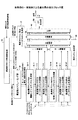
図7Aはデータチャネル及び制御チャネルのマッピング例を示す。図示のマッピング例は、1つの周波数ブロック及び1つのサブフレームに関するものであり、概して第1多重部1−xの出力内容に相当する(但し、パイロットチャネル等は第3多重部38で多重される。)。1つのサブフレームは例えば1つの送信時間間隔(TTI)に対応してもよいし、複数のTTIに対応してもよい。図示の例では、周波数ブロックに7つのリソースブロックRB1〜7が含まれている。この7つのリソースブロックは、図3の周波数スケジューリング部32によって、チャネル状態の良い端末に割り当てられる。
FIG. 7A shows an example of data channel and control channel mapping. The illustrated mapping example relates to one frequency block and one subframe, and generally corresponds to the output content of the first multiplexing unit 1-x (however, the pilot channel and the like are multiplexed by the third multiplexing unit 38). .) One subframe may correspond to, for example, one transmission time interval (TTI) or may correspond to a plurality of TTIs. In the illustrated example, seven resource blocks RB1 to RB7 are included in the frequency block. These seven resource blocks are allocated to terminals having good channel conditions by the
概して、不特定制御チャネル等、パイロットチャネル等及びデータチャネル等は時間多重されている。不特定制御チャネルは周波数ブロックの全域にわたって分散してマッピングされている。即ち不特定制御チャネルは7つのリソースブロックの占める帯域全体にわたって分散している。図示の例では不特定制御チャネルと他の制御チャネル(特定制御チャネルを除く)とが周波数多重されている。他のチャネルには例えば同期チャネル等が含まれてもよい。図示の例では不特定制御チャネル及び他の制御チャネルは、何らかの間隔を隔てて並んだ複数の周波数成分を各々が有するように周波数多重される。このような多重化方式は、ディストリビュート周波数分割多重化(distributed FDM)方式と呼ばれる。周波数成分同士の間隔は全て同じでもよいし異なっていてもよい。いずれにせよ、不特定制御チャネルが1つの周波数ブロックの全域にわたって分散していることを要する。 In general, unspecified control channels, pilot channels, and data channels are time-multiplexed. The unspecified control channel is distributed and mapped over the entire frequency block. That is, the unspecified control channel is distributed over the entire band occupied by the seven resource blocks. In the illustrated example, the non-specific control channel and other control channels (excluding the specific control channel) are frequency-multiplexed. Other channels may include, for example, a synchronization channel. In the illustrated example, the unspecified control channel and the other control channels are frequency-multiplexed so that each has a plurality of frequency components arranged at some interval. Such a multiplexing scheme is called a distributed frequency division multiplexing (distributed FDM) scheme. The intervals between the frequency components may all be the same or different. In any case, it is necessary that the unspecified control channel is distributed over the entire area of one frequency block.
図示の例ではパイロットチャネル等も周波数ブロック全域にわたってマッピングされている。様々な周波数成分についてのチャネル推定等を正確に行う観点からは、図示のようにパイロットチャネルが広範囲にマッピングされていることが望ましい。 In the illustrated example, pilot channels and the like are also mapped over the entire frequency block. From the viewpoint of accurately performing channel estimation and the like for various frequency components, it is desirable that the pilot channel is mapped over a wide range as illustrated.
図示の例ではリソースブロックRB1,RB2,RB4はユーザ1(UE1)に割り当てられ、リソースブロックRB3,RB5,RB6はユーザ2(UE2)に割り当てられ、リソースブロックRB7はユーザ3(UE3)に割り当てられる。上述したようにこのような割り当て情報は不特定制御チャネルに含まれている。更に、ユーザ1に割り当てられたリソースブロックの内のリソースブロックRB1の先頭に、ユーザ1に関する特定制御チャネルがマッピングされている。ユーザ2に割り当てられたリソースブロックの内のリソースブロックRB3の先頭には、ユーザ2に関する特定制御チャネルがマッピングされている。ユーザ3に割り当てられたリソースブロックRB7の先頭には、ユーザ3に関する特定制御チャネルがマッピングされている。図中、ユーザ1,2,3の特定制御チャネルの占める大きさが不均一に描かれている点に留意を要する。これは、特定制御チャネルの情報量がユーザにより異なってよいことを表す。特定制御チャネルはデータチャネルに割り当てられたリソースブロックに限定して局所的にマッピングされる。この点、様々なリソースブロックにわたって分散してマッピングされるディストリビュートFDMと異なり、このようなマッピング方式はローカライズド周波数分割多重(localized FDM)とも呼ばれる。
In the illustrated example, resource blocks RB1, RB2, and RB4 are assigned to user 1 (UE1), resource blocks RB3, RB5, and RB6 are assigned to user 2 (UE2), and resource block RB7 is assigned to user 3 (UE3). . As described above, such allocation information is included in the unspecified control channel. Furthermore, a specific control channel for
図7Bは不特定制御チャネルの別のマッピング例を示す。ユーザ1(UE1)の特定制御チャネルは、図7Aでは1つのリソースブロックRB1だけにマッピングされていたが、図7BではリソースブロックRB1,RB2,RB4全体(ユーザ1に割り当てられたリソースブロック全体)にわたってディストリビュートFDM方式で離散的に分散してマッピングされている。また、ユーザ2(UE2)に関する特定制御チャネルも、図7Aに示される場合とは異なり、リソースブロックRB3,RB5,RB6全体にわたってマッピングされている。ユーザ2の特定制御チャネルと共有データチャネルは時分割多重されている。このように、各ユーザの特定制御チャネル及び共有データチャネルは、各ユーザに割り当てられた1以上のリソースブロックの全部又は一部の中で、時分割多重(TDM)方式で及び/又は周波数分割多重方式で(ローカライズドFDM方式及びディストリビュートFDM方式を含む)多重されてもよい。2以上のリソースブロックにわたって特定制御チャネルをマッピングすることで、特定制御チャネルについても周波数ダイバーシチ効果を期待することができ、特定制御チャネルの更なる信号品質の向上を図ることができる。
FIG. 7B shows another example of mapping of unspecified control channels. The specific control channel of user 1 (UE1) is mapped to only one resource block RB1 in FIG. 7A, but over the entire resource blocks RB1, RB2, and RB4 (entire resource blocks assigned to user 1) in FIG. 7B. The distributed FDM method is discretely distributed and mapped. Also, the specific control channel for user 2 (UE2) is also mapped over the entire resource blocks RB3, RB5, RB6, unlike the case shown in FIG. 7A.
図8は本発明の一実施例で使用される移動端末の部分ブロック図を示す。図8にはキャリア周波数同調部81、フィルタリング部82、サイクリックプレフィックス(CP)除去部83、高速フーリエ変換部(FFT)84、CQI測定部85、報知チャネル(又はページングチャネル)復号部86、不特定制御チャネル復号部87、特定制御チャネル復号部88及びデータチャネル復号部89が描かれている。
FIG. 8 shows a partial block diagram of a mobile terminal used in an embodiment of the present invention. FIG. 8 shows a carrier
キャリア周波数同調部81は端末に割り当てられている周波数ブロックの信号を受信できるように受信帯域の中心周波数を適切に調整する。
The carrier
フィルタリング部82は受信信号をフィルタリングする。
The
サイクリックプレフィックス除去部83は受信信号からガードインターバルを除去し、受信シンボルから有効シンボル部分を抽出する。
The cyclic
高速フーリエ変換部(FFT)84は有効シンボルに含まれる情報を高速フーリエ変換し、OFDM方式の復調を行う。 A fast Fourier transform unit (FFT) 84 performs fast Fourier transform on information included in the effective symbol and performs OFDM demodulation.
CQI測定部85は受信信号に含まれているパイロットチャネルの受信電力レベルを測定し、測定結果をチャネル状態情報CQIとして基地局にフィードバックする。CQIは周波数ブロック内の全てのリソースブロック毎に行われ、それらが全て基地局に報告される。
報知チャネル(又はページングチャネル)復号部86は報知チャネルを復号する。ページングチャネルが含まれている場合にはそれも復号する。
The broadcast channel (or paging channel)
不特定制御チャネル復号部87は受信信号に含まれている不特定制御チャネルを復号し、スケジューリング情報を抽出する。スケジューリング情報には、その端末宛の共有データチャネルにリソースブロックが割り当てられているか否かを示す情報、割り当てられている場合にはリソースブロック番号を示す情報等が含まれる。 The unspecified control channel decoding unit 87 decodes the unspecified control channel included in the received signal and extracts scheduling information. The scheduling information includes information indicating whether or not a resource block is allocated to the shared data channel addressed to the terminal, information indicating a resource block number when the resource block is allocated, and the like.
特定制御チャネル復号部88は受信信号に含まれている特定制御チャネルを復号する。特定制御チャネルは共有データチャネルに関するデータ変調、チャネル符号化率及びHARQの情報が含まれる。
The specific control
データチャネル復号部89は、特定制御チャネルから抽出した情報に基づいて、受信信号に含まれている共有データチャネルを復号する。復号結果に応じて肯定応答(ACK)又は否定応答(NACK)が基地局に報告されてもよい。 The data channel decoding unit 89 decodes the shared data channel included in the received signal based on the information extracted from the specific control channel. An acknowledgment (ACK) or a negative acknowledgment (NACK) may be reported to the base station according to the decoding result.
図9は本発明の一実施例による動作例を示すフローチャートである。一例として、10MHzの帯域幅で通信可能な移動端末UE1を有するユーザが、20MHzの帯域幅で通信を行っているセル又はセクタに入ったとする。通信システムの最低周波数帯域は5MHzであり、図2に示されるように全帯域が4つの周波数ブロック1〜4に分かれているものとする。
FIG. 9 is a flowchart showing an operation example according to an embodiment of the present invention. As an example, it is assumed that a user having a mobile terminal UE1 that can communicate with a bandwidth of 10 MHz enters a cell or a sector that performs communication with a bandwidth of 20 MHz. It is assumed that the minimum frequency band of the communication system is 5 MHz, and the entire band is divided into four
ステップS11では、端末UE1は基地局からの報知チャネルを受信し、自局が使用可能な周波数ブロックが何であるかを確認する。報知チャネルは全20MHzの帯域の中心周波数を含む5MHzの帯域で送信されていてもよい。このようにすることで、受信可能な帯域幅の異なるどの端末も報知チャネルを簡易に受信することができる。報知チャネルは、10MHzの帯域幅で通信するユーザに対して、周波数ブロック(1,2)、(2,3)又は(3,4)のような隣接する2つの周波数ブロックの組み合わせの使用を許可する。これら全ての使用が許可されてもよいし、或いは何れかの組み合わせに使用が制限されてもよい。一例として周波数ブロック2,3の使用が許可されたとする。 In step S11, the terminal UE1 receives the broadcast channel from the base station, and confirms what frequency blocks the local station can use. The broadcast channel may be transmitted in a 5 MHz band including the center frequency of the entire 20 MHz band. In this way, any terminal having a different receivable bandwidth can easily receive the broadcast channel. The broadcast channel allows users communicating with a bandwidth of 10 MHz to use a combination of two adjacent frequency blocks such as frequency blocks (1, 2), (2, 3) or (3,4). To do. Use of all of these may be permitted, or use may be limited to any combination. As an example, it is assumed that use of the frequency blocks 2 and 3 is permitted.
ステップS12では、端末UE1は下りパイロットチャネルを受信し、周波数ブロック2,3に関する受信信号品質を測定する。測定は各周波数ブロックに含まれている多数のリソースブロック毎に行われ、それら全てがチャネル状態情報CQIとして基地局に報告される。 In step S12, the terminal UE1 receives the downlink pilot channel and measures the received signal quality regarding the frequency blocks 2 and 3. The measurement is performed for each of a number of resource blocks included in each frequency block, and all of them are reported to the base station as channel state information CQI.
ステップS21では、基地局は端末UE1及び他の端末から報告されたチャネル状態情報CQIに基づいて、周波数ブロック毎に周波数スケジューリングを行う。UE1宛のデータチャネルは周波数ブロック2又は3から伝送されることは、周波数ブロック割当制御部(図3の31)で確認及び管理されている。
In step S21, the base station performs frequency scheduling for each frequency block based on the channel state information CQI reported from the terminal UE1 and other terminals. It is confirmed and managed by the frequency block allocation control unit (31 in FIG. 3) that the data channel addressed to UE1 is transmitted from
ステップS22では、基地局はスケジューリング情報に従って制御シグナリングチャネルを周波数ブロック毎に作成する。制御シグナリングチャネルには不特定制御チャネル及び特定制御チャネルが含まれている。 In step S22, the base station creates a control signaling channel for each frequency block according to the scheduling information. The control signaling channel includes an unspecified control channel and a specified control channel.
ステップS23ではスケジューリング情報に従って制御チャネル及び共有データチャネルが周波数ブロック毎に基地局から送信される。 In step S23, the control channel and the shared data channel are transmitted from the base station for each frequency block according to the scheduling information.
ステップS13では、端末UE1は周波数ブロック2及び3で伝送される信号を受信する。 In step S13, the terminal UE1 receives signals transmitted in the frequency blocks 2 and 3.
ステップS14では、周波数ブロック2で受信した制御チャネルから不特定制御チャネルを分離し、それを復号し、スケジューリング情報を抽出する。同様に周波数ブロック3で受信した制御チャネルからも不特定制御チャネルを分離し、それを復号し、スケジューリング情報を抽出する。いずれのスケジューリング情報にも、端末UE1宛の共有データチャネルにリソースブロックが割り当てられているか否かを示す情報、割り当てられている場合にはリソースブロック番号を示す情報等が含まれる。自局宛の共有データチャネルに何らのリソースブロックも割り当てられていなかった場合には、端末UE1は待ち受け状態に戻り、制御チャネルの受信を待機する。自局宛の共有データチャネルに何らのかのリソースブロックが割り当てられていた場合には、端末UE1は、ステップS15で受信信号に含まれている特定制御チャネルを分離し、それを復号する。特定制御チャネルは共有データチャネルに関するデータ変調、チャネル符号化率及びHARQの情報が含まれている。
In step S14, the unspecified control channel is separated from the control channel received in the
ステップS16では、端末UE1は、特定制御チャネルから抽出した情報に基づいて、受信信号に含まれている共有データチャネルを復号する。復号結果に応じて肯定応答(ACK)又は否定応答(NACK)が基地局に報告されてもよい。以後同様の手順が反復される。 In step S16, the terminal UE1 decodes the shared data channel included in the received signal based on the information extracted from the specific control channel. An acknowledgment (ACK) or a negative acknowledgment (NACK) may be reported to the base station according to the decoding result. Thereafter, the same procedure is repeated.
第1実施例では制御チャネルが、リソースブロックの割り当てられた端末が復号及び復調しなければならない特定制御チャネルとそれ以外に分けられ、特定制御チャネルは割り当てられたリソースブロックに限定してマッピングされ、他の制御チャネルは周波数帯域全域にわたってマッピングされていた。これにより制御チャネルに関する伝送効率の向上や高品質化等を図ることができる。しかしながら本発明はこのような伝送方法例に限定されない。 In the first embodiment, the control channel is divided into a specific control channel that the terminal to which the resource block is allocated must decode and demodulate, and the specific control channel is mapped only to the allocated resource block, Other control channels were mapped over the entire frequency band. As a result, the transmission efficiency and quality of the control channel can be improved. However, the present invention is not limited to such a transmission method example.
図7Cは本発明の第2実施例によるデータチャネル及び制御チャネルのマッピング例を示す図である。本実施例でも図3に示されるような基地局が使用される。この場合、制御チャネルに関して図4Bに示される処理要素が主に使用される。本実施例では特定制御情報も不特定制御情報も明確には区別されず、複数のリソースブロックにわたる周波数帯域全域で送信される。図4Bに示されるように本実施例では複数のユーザに関する制御チャネル全体を1つの処理単位として誤り訂正符号化がなされる。ユーザ装置(典型的には、移動局)は制御チャネルを復号及び復調し、自局が割り当てられているか否かを判別し、チャネル割当情報に従って特定のリソースブロックで伝送されるデータチャネルを復元する。 FIG. 7C is a diagram illustrating an example of data channel and control channel mapping according to the second embodiment of the present invention. Also in this embodiment, a base station as shown in FIG. 3 is used. In this case, the processing elements shown in FIG. 4B for the control channel are mainly used. In this embodiment, neither specific control information nor non-specific control information is clearly distinguished, and is transmitted over the entire frequency band over a plurality of resource blocks. As shown in FIG. 4B, in this embodiment, error correction coding is performed using the entire control channel for a plurality of users as one processing unit. A user apparatus (typically a mobile station) decodes and demodulates the control channel, determines whether or not the own station is allocated, and restores a data channel transmitted in a specific resource block according to the channel allocation information. .
例えば、リソースブロックの割り当てられた第1〜第3ユーザUE1,UE2,UE3にそれぞれ10ビットの制御情報が伝送されるとする。3人分の制御情報30ビット全体が1つの処理単位として誤り訂正符号化さる。符号化率(R)が1/2であったとすると、30×2=60ビットが生成され、送信される。一方、本実施例とは異なり、各人の制御情報を個々に誤り訂正符号化して伝送することも考えられる。その場合は1人分の制御情報10ビットが誤り訂正符号化され、10×2=20ビットが生成され、それが3人分(合計60ビット)用意される。伝送すべき制御情報量はいずれも60ビットになるが、本実施例によれば誤り訂正符号化の処理単位が、他方よりも3倍長いので、本実施例は符号化利得を高くする(即ち、誤りにくくする)観点から有利である。更に、本実施例では60ビット全体に誤り検出ビット(CRCビット等)が付加されるが、ユーザ毎に誤り訂正符号化した場合は20ビット毎に誤り検出ビットが付加されることになる。従って検出ビットによるオーバーヘッドの増加を抑制する観点からも、本実施例の方が有利である。 For example, it is assumed that 10-bit control information is transmitted to each of the first to third users UE1, UE2, UE3 to which resource blocks are assigned. The entire 30 bits of control information for three persons are error-correction coded as one processing unit. If the coding rate (R) is 1/2, 30 × 2 = 60 bits are generated and transmitted. On the other hand, unlike the present embodiment, it is also conceivable that each person's control information is individually error correction encoded and transmitted. In that case, 10 bits of control information for 1 person are error-correction-encoded to generate 10 × 2 = 20 bits, which are prepared for 3 persons (60 bits in total). The amount of control information to be transmitted is 60 bits, but according to this embodiment, the processing unit of error correction coding is three times longer than the other, so this embodiment increases the coding gain (ie, This is advantageous from the viewpoint of making errors less likely to occur. Further, in this embodiment, error detection bits (CRC bits, etc.) are added to the entire 60 bits, but when error correction coding is performed for each user, error detection bits are added every 20 bits. Therefore, this embodiment is more advantageous from the viewpoint of suppressing an increase in overhead due to the detection bits.
図7Dは本発明の第3実施例によるデータチャネル及び制御チャネルのマッピング例を示す図である。本実施例でも図3に示されるような基地局が使用されるが、制御チャネルに関しては図4Cに示される処理要素が主に使用される。本実施例でも特定制御情報及び不特定制御情報が明確には区別されないが、制御チャネルはそれを受信すべきユーザに割り当てられたリソースブロックに限定してマッピングされる。例えば第1ユーザUE1の制御チャネルは第1及び第2リソースブロックRB1,RB2にマッピングされ、第2ユーザUE2の制御チャネルは第3及び第4リソースブロックRB3,RB4にマッピングされ、第3ユーザUE3の制御チャネルは第5リソースブロックRB5にマッピングされている。誤り訂正符号化はユーザ毎に行われる。この点、第1〜第3ユーザの制御チャネルがまとめて誤り訂正符号化されてリソースブロックRB1〜RB5にマッピングされている第2実施例と異なる。 FIG. 7D is a diagram illustrating an example of data channel and control channel mapping according to the third embodiment of the present invention. In this embodiment, the base station as shown in FIG. 3 is used, but the processing elements shown in FIG. 4C are mainly used for the control channel. In this embodiment, the specific control information and the non-specific control information are not clearly distinguished, but the control channel is mapped only to the resource block assigned to the user who should receive it. For example, the control channel of the first user UE1 is mapped to the first and second resource blocks RB1 and RB2, the control channel of the second user UE2 is mapped to the third and fourth resource blocks RB3 and RB4, and the third user UE3 The control channel is mapped to the fifth resource block RB5. Error correction coding is performed for each user. This is different from the second embodiment in which the control channels of the first to third users are collectively error-corrected and mapped to the resource blocks RB1 to RB5.
本実施例では制御チャネルもデータチャネルも同じリソースブロックに限定されているが、制御チャネル受信前に移動局にどのリソースブロックが割り当てられているかはその移動局にとって未知である。従って各移動局は制御チャネルがマッピングされる可能性のあるリソースブロックを全て受信し、自局だけでなく他局の制御チャネルを復調する必要がある。図7Dに示される例では第1ユーザUE1は全リソースブロックRB1〜RB5にマッピングされた制御チャネルを復調することで、第1及び第2リソースブロックRB1,RB2に自局が割り当てられていることを知ることができる。 In this embodiment, both the control channel and the data channel are limited to the same resource block, but it is unknown to the mobile station which resource block is allocated to the mobile station before receiving the control channel. Therefore, each mobile station needs to receive all the resource blocks to which the control channel can be mapped, and demodulate not only the own station but also the control channel of the other station. In the example shown in FIG. 7D, the first user UE1 demodulates the control channel mapped to all the resource blocks RB1 to RB5, thereby confirming that its own station is allocated to the first and second resource blocks RB1 and RB2. I can know.
第2実施例では最悪の通信環境にいるユーザが制御チャネルを所要品質で受信できるようにするため、その最悪環境のユーザにあわせて基地局の送信電力が決定される。従って最悪でない通信環境のユーザにとっては過剰品質になり、基地局は余分な電力を常に消費しなければならない。しかしながら第3実施例では誤り訂正符号化等の処理や送信帯域が各ユーザのリソースブロックに限定してなされるので、送信電力制御もユーザ毎に行うことができる。このため基地局の電力を余分に多く消費しなくて済む。また、リソースブロックはチャネル状態の良好なユーザに割り当てられるので、そのような良好なチャネル状態で制御チャネルが伝送され、制御チャネルの高品質化を図ることができる。 In the second embodiment, in order for a user in the worst communication environment to receive the control channel with the required quality, the transmission power of the base station is determined in accordance with the user in the worst environment. Therefore, it becomes excessive quality for users in the worst communication environment, and the base station must always consume extra power. However, in the third embodiment, processing such as error correction coding and the transmission band are limited to each user's resource block, so transmission power control can also be performed for each user. For this reason, it is not necessary to consume extra power of the base station. Further, since the resource block is assigned to a user with a good channel state, the control channel is transmitted in such a good channel state, and the quality of the control channel can be improved.
図7Eは本発明の第4実施例によるデータチャネル及び制御チャネルのマッピング例を示す図である。本実施例でも図3に示されるような基地局が使用されるが、制御チャネルに関する処理要素は図4Dに示されるようになる。本実施例でも特定制御情報及び不特定制御情報が明確には区別されず、制御チャネルは第3実施例と同様に個々のユーザ毎に誤り訂正符号化され、送信電力が決定される。但し、制御チャネルはそれを受信すべきユーザに割り当てられたリソースブロックだけでなく、他のリソースブロックにも分散されるようにマッピングされる。このようにしても制御チャネルを伝送することができる。 FIG. 7E is a diagram illustrating an example of data channel and control channel mapping according to the fourth embodiment of the present invention. In this embodiment, a base station as shown in FIG. 3 is used, but the processing elements related to the control channel are as shown in FIG. 4D. In the present embodiment, the specific control information and the non-specific control information are not clearly distinguished, and the control channel is subjected to error correction coding for each user as in the third embodiment, and the transmission power is determined. However, the control channel is mapped so as to be distributed not only to the resource block assigned to the user who should receive it but also to other resource blocks. Even in this way, the control channel can be transmitted.
なお、第1乃至第4実施例において、複数のリソースブロックに制御チャネルを分散してマッピングする場合に、所与の周波数帯域中の全てのリソースブロックに制御チャネルがマッピングされることは必須ではない。例えば所与の周波数帯域中の奇数番目のリソースブロックRB1,RB3,…にのみ利制御チャネルがマッピングされてもよいし、偶数番目のリソースブロックにのみマッピングされてもよい。基地局及び移動局間で既知の適切な如何なるリソースブロックでもそこに限定して制御チャネルがマッピングされてよい。そのようにすることで、移動局が自局の割当情報を抽出する際のサーチ範囲を適切に狭めることができる。 In the first to fourth embodiments, when the control channels are distributed and mapped to a plurality of resource blocks, it is not essential that the control channels are mapped to all resource blocks in a given frequency band. . For example, the interest control channel may be mapped only to odd-numbered resource blocks RB1, RB3,... In a given frequency band, or may be mapped only to even-numbered resource blocks. The control channel may be mapped only to any appropriate resource block known between the base station and the mobile station. By doing so, it is possible to appropriately narrow the search range when the mobile station extracts its own allocation information.
ところで、第2実施例では最悪の通信環境にいるユーザに合わせて基地局の送信電力が決定され、基地局は余分な電力を常に消費しなければならない点が指摘された。しかしながら、多数のユーザの通信環境が仮に同程度に良好であれば、そのような懸念は解消される。従って複数のユーザにとって同程度の品質が得られる通信環境では、第2実施例で説明された手法は有利である。このような観点から、本発明の第5実施例ではセル内のユーザ装置が適切にグループ化され、グループ毎に使用周波数帯域が分割される。 By the way, in the second embodiment, it is pointed out that the transmission power of the base station is determined according to the user in the worst communication environment, and the base station must always consume extra power. However, if the communication environment of a large number of users is as good as that, such a concern is resolved. Therefore, the method described in the second embodiment is advantageous in a communication environment in which the same quality can be obtained for a plurality of users. From this point of view, in the fifth embodiment of the present invention, user devices in the cell are appropriately grouped, and the used frequency band is divided for each group.
図7Fは本発明の第5実施例を説明するための概念図を示す。図示の例では基地局からの距離に応じて3つのグループが用意され、グループ1にはリソースブロックRB1〜RB3が、グループ2にはリソースブロックRB4〜RB6が、グループ3にはリソースブロックRB7〜RB9がそれぞれ割り当てられている。用意されるグループ数及びリソースブロック数は一例に過ぎず、適切な如何なる数が使用されてもよい。グループ化された後に第1乃至第4実施例で説明された各種の各手法が行われてよい。ユーザ及び周波数帯域をグループ分けすることで、ユーザ間の受信品質の優劣の差を小さくすることができる。これにより、最悪環境のユーザに起因して基地局の送信電力が余分に多く消費されてしまう問題(第2実施例で懸念された問題)に効果的に対処することができる。また、第3実施例の場合でも本実施例のようにグループ化を行うことで、同一グループ内での制御チャネルの送信電力が同程度になり、基地局送信機の動作の安定化を図る等の観点から有利になる。
FIG. 7F shows a conceptual diagram for explaining a fifth embodiment of the present invention. In the illustrated example, three groups are prepared according to the distance from the base station,
図示の例では説明の簡明化を図るために、基地局からの距離に応じて3つのグループが用意された。しかしながら、距離だけでなくチャネル品質インジケータ(CQI)に基づいてグループ分けがなされてもよい。CQIはSIRやSINR等の当該技術分野で既知の適切な如何なる量で測定されてもよい。 In the illustrated example, three groups are prepared according to the distance from the base station in order to simplify the description. However, groupings may be made based on channel quality indicators (CQI) as well as distances. CQI may be measured in any suitable amount known in the art, such as SIR or SINR.
図10は周波数ホッピングが行われる場合の動作例を示す図である。通信システムに割り当てられた周波数帯域は20MHzであり、5MHzの最低帯域幅を有する周波数ブロック4つが含まれている。図示の例では通信システムは、5MHzの帯域で通信可能なユーザを40人、10MHzの帯域で通信可能なユーザを20人、20MHzの帯域で通信可能なユーザを10人収容することができる。 FIG. 10 is a diagram illustrating an operation example when frequency hopping is performed. The frequency band assigned to the communication system is 20 MHz, and includes four frequency blocks having a minimum bandwidth of 5 MHz. In the illustrated example, the communication system can accommodate 40 users who can communicate in a 5 MHz band, 20 users who can communicate in a 10 MHz band, and 10 users who can communicate in a 20 MHz band.
20MHzの帯域で通信可能なユーザは、周波数ブロック1〜4の全部を常に使用可能である。しかしながら、5MHzの帯域でしか通信できない40人のユーザのうち、1番目から10番目までのユーザは、時刻tでは周波数ブロック1だけを使用することが許可され、時刻t+1では周波数ブロック2だけを使用することが許可され、時刻t+2では周波数ブロック3だけを使用することが許可されている。11番目から20番目までのユーザは、時刻t,t+1,t+2で周波数ブロック2,3,4を使用することが許可されている。21番目から30番目までのユーザは、時刻t,t+1,t+2で周波数ブロック3,4,1を使用することが許可されている。31番目から40番目までのユーザは、時刻t,t+1,t+2で周波数ブロック4,1,2を使用することが許可されている。また、10MHzの帯域でしか通信できない20人のユーザのうち、1番目から10番目までのユーザは、時刻tでは周波数ブロック1及び2だけを使用することが許可され、時刻t+1では周波数ブロック3及び4だけを使用することが許可され、時刻t+2では周波数ブロック1及び2だけを使用することが許可されている。11番目から20番目までのユーザは、時刻t,t+1,t+2で周波数ブロック3及び4,1及び2,3及び4を使用することが許可されている。
A user who can communicate in a 20 MHz band can always use all of the frequency blocks 1 to 4. However, out of 40 users who can communicate only in the 5 MHz band, the first to tenth users are allowed to use
このような周波数ホッピングパターンは報知チャネル又は別の手法で各ユーザに事前に通知されている。この場合に、周波数ホッピングパターンとして事前にいくつかのパターンが規定され、その内のどのパターンが使用されるかを示すパターン番号をユーザに通知することで、少ないビット数で周波数ホッピングパターンをユーザに通知することができる。本実施例のように使用可能な周波数ブロックに幾つかの選択肢がある場合に、使用可能な周波数ブロックを通信開始後に変更することは、ユーザ間及び周波数ブロック間で通信品質の均一化を図る観点から好ましい。例えば本実施例のように周波数ホッピングが行われなかったならば、周波数ブロック間で通信品質の優劣の差が大きかった場合に、特定のユーザは常に悪い品質で通信しなければならない。周波数ホッピングを行うことで、ある時点では通信品質が悪かったとしても別の時点では良くなることが期待できる。 Such a frequency hopping pattern is notified to each user in advance by a broadcast channel or another method. In this case, several patterns are defined in advance as frequency hopping patterns, and by notifying the user of the pattern number indicating which pattern is used, the frequency hopping pattern can be transmitted to the user with a small number of bits. You can be notified. In the case where there are several choices of usable frequency blocks as in the present embodiment, changing the usable frequency block after the start of communication is a viewpoint of achieving uniform communication quality between users and between frequency blocks. To preferred. For example, if frequency hopping is not performed as in the present embodiment, a specific user must always communicate with a bad quality when there is a large difference in communication quality between frequency blocks. By performing frequency hopping, even if the communication quality is bad at one point, it can be expected to improve at another point.
図示の例では5MHz及び10MHzの周波数ブロックが1つずつ右にシフトしてゆく周波数ホッピングパターンが示されているが、それ以外の様々なホッピングパターンが使用されてもよい。どのようなホッピングパターンが採用されたとしても、送信側及び受信側でそれが既知であればよいからである。 In the illustrated example, a frequency hopping pattern in which 5 MHz and 10 MHz frequency blocks are shifted to the right one by one is shown, but various other hopping patterns may be used. This is because no matter what hopping pattern is adopted, it should be known on the transmission side and the reception side.
以下に説明される本発明の第3実施例では制御シグナリングチャネルに加えてページングチャネルを伝送する手法が説明される。 In the third embodiment of the present invention described below, a method for transmitting a paging channel in addition to a control signaling channel will be described.
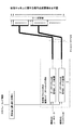
図11は本発明の一実施例による動作例のフローチャート(左側)及び周波数帯域(右側)を示す図である。ステップS1では基地局から配下のユーザに報知チャネルが送信されている。図11(1)に示されるように、報知チャネルは全周波数帯域の中心周波数を含む最低帯域幅で伝送される。報知チャネルで通知される報知情報には、ユーザの受信可能な帯域幅と使用可能な周波数ブロックとの対応関係が含まれている。 FIG. 11 is a diagram showing a flowchart (left side) and a frequency band (right side) of an operation example according to one embodiment of the present invention. In step S1, the broadcast channel is transmitted from the base station to the subordinate users. As shown in FIG. 11 (1), the broadcast channel is transmitted with the minimum bandwidth including the center frequency of the entire frequency band. The broadcast information notified through the broadcast channel includes the correspondence between the bandwidth that can be received by the user and the usable frequency blocks.
ステップS2ではユーザ(例えばUE1)は指定された周波数ブロック(例えば、周波数ブロック1)で待ち受け状態に入る。この場合に、ユーザUE1は使用の許可された周波数ブロック1の信号を受信できるように、受信信号の帯域を調整する。本実施例では、周波数ブロック1でユーザUE1に関する制御シグナリングチャネルだけでなく、ユーザUE1に関するページングチャネルも伝送される。ページングチャネルでユーザUE1の呼び出されたことが確認されると、フローはステップS3に進む。
In step S2, a user (for example, UE1) enters a standby state at a designated frequency block (for example, frequency block 1). In this case, the user UE1 adjusts the band of the received signal so that the signal of the
ステップS3では指示された周波数ブロックでスケジューリング情報に従ってデータチャネルが受信される。ユーザUE1は以後再び待ち受け状態に戻る。 In step S3, the data channel is received in accordance with the scheduling information at the designated frequency block. Thereafter, the user UE1 returns to the standby state again.
図12は本発明の一実施例による別の動作例のフローチャート(左側)及び周波数帯域(右側)を示す図である。上記と同様にステップS1では基地局から報知チャネルが送信され、報知チャネルは全周波数帯域の中心周波数を含む最低帯域幅で伝送される(図12(1))。図11の例と同様に使用可能な周波数ブロックは周波数ブロック1であるとする。
FIG. 12 is a diagram showing a flowchart (left side) and a frequency band (right side) of another operation example according to one embodiment of the present invention. In the same manner as described above, in step S1, a broadcast channel is transmitted from the base station, and the broadcast channel is transmitted with the minimum bandwidth including the center frequency of all frequency bands (FIG. 12 (1)). Assume that the frequency block that can be used is the
ステップS2ではユーザUE1は待ち受け状態に入る。上記の例とは異なり、ユーザUE1はこの時点では受信信号の帯域を調整しない。従って報知チャネルを受信するのと同じ帯域でページングチャネルを待機する(図12(2))。 In step S2, the user UE1 enters a standby state. Unlike the above example, the user UE1 does not adjust the band of the received signal at this point. Therefore, the paging channel is waited in the same band as the broadcast channel is received ((2) in FIG. 12).
ステップS3ではページングチャネルが確認された後に、端末は自局に割り当てられた周波数ブロック1に移行し、制御シグナリングチャネルを受信し、スケジューリング情報に従って通信を行う(図12(3))。ユーザUE1は以後再び待ち受け状態に戻る。
In step S3, after the paging channel is confirmed, the terminal moves to
図11に示される例では端末は待ち受け時に周波数ブロック1に速やかに移行するが、図12に示される例では端末はその時点では移行せず自局の呼び出しが確認された後に周波数ブロック1に移行する。前者の手法では様々なユーザが各自に割り当てられた周波数ブロックで信号を待ち受けるが、後者の手法では全てのユーザが同じ帯域で信号を待ち受ける。従って前者は後者に比べて周波数資源を均一に使用する点で好ましいかもしれない。一方、ハンドオーバの要否を確認するための周辺セルサーチは、全帯域中央の最低帯域幅を用いて行われる。従って、端末の周波数同調回数を少なくする観点からは、図12に示される例のように待ち受け時の帯域とセルサーチの帯域を合わせることが望ましい。
In the example shown in FIG. 11, the terminal quickly shifts to
ところで、制御チャネルの受信信号品質を高める観点からはリンクアダプテーションを行うことが望ましい。本発明の第4実施例ではリンクアダプテーションを行う手法として送信電力制御(TPC: Transmission Power Control)及び適応変調符号化(AMC: Adaptive Modulation and Coding)制御が使用される。図13は送信電力制御が行われる様子を示し、下りリンクチャネルの送信電力を制御することで受信側で所要品質を達成することが意図される。より具体的には基地局から遠いユーザ1に対するチャネル状態は悪いことが予想されるので、大きな送信電力で下りリンクチャネルが送信される。逆に、基地局に近いユーザ2に対してはチャネル状態の良いことが予想される。この場合に、ユーザ2への下りリンクチャネルの送信電力が大きかったとすると、ユーザ2にとっての受信信号品質は良いかもしれないが、他のユーザにとっては干渉が大きくなってしまう。ユーザ2のチャネル状態は良いので、送信電力は小さくても所要品質を確保することはできる。従ってこの場合は比較的小さな送信電力で下りリンクチャネルが送信される。送信電力制御が単独に行われる場合には変調方式及びチャネル符号化方式は一定に維持され、送信側及び受信側で既知の組み合わせが使用される。従って、送信電力制御のもとでチャネルを復調するのに、変調方式等が別途通知されることは不要である。
By the way, it is desirable to perform link adaptation from the viewpoint of improving the received signal quality of the control channel. In the fourth embodiment of the present invention, transmission power control (TPC) and adaptive modulation and coding (AMC) control are used as methods for performing link adaptation. FIG. 13 shows how transmission power control is performed, and it is intended to achieve the required quality on the receiving side by controlling the transmission power of the downlink channel. More specifically, since the channel state for the
図14は適応変調符号化制御が行われる様子を示し、チャネル状態の良否に応じて変調方式及び符号化方式の双方又は一方を適応的に変えることで、受信側での所要品質を達成することが意図される。より具体的には、基地局からの送信電力が一定であったとすると、基地局から遠いユーザ1に対するチャネル状態は悪いことが予想されるので、変調多値数は小さく及び/又はチャネル符号化率も小さく設定される。図示の例ではユーザ1に対する変調方式にQPSKが使用され、1シンボル当たり2ビットの情報が伝送される。これに対して基地局に近いユーザ2に対してはチャネル状態の良いことが予想され、変調多値数は大きく及び/又はチャネル符号化率も大きく設定される。図示の例ではユーザ2に対する変調方式に16QAMが使用され、1シンボル当たり4ビットの情報が伝送される。これによりチャネル状態の悪いユーザに対しては信頼度を高めることで所要品質が達成され、チャネル状態の良いユーザに対しては所要品質を維持しつつスループットを向上させることができる。適応変調符号化制御では受信したチャネルを復調する際に、そのチャネルに施された変調方式、符号化方式、シンボル数等の情報が必要であるので、何らかの手段でその情報が受信側に通知されることを要する。また、チャネル状態の良否に応じて1シンボル当たりに伝送可能なビット数が異なるので、チャネル状態が良ければ少ないシンボル数で情報を伝送できる反面、そうでなければ多くのシンボル数を必要としてしまう。
FIG. 14 shows a state in which adaptive modulation and coding control is performed. The required quality on the receiving side is achieved by adaptively changing either or both of the modulation method and the coding method according to the quality of the channel state. Is intended. More specifically, if the transmission power from the base station is constant, the channel state for the
本発明の第4実施例では、不特定のユーザが復号しなければならない不特定制御チャネルについて送信電力制御が行われ、リソースブロックの割り当てられた特定のユーザが復号すればよい特定制御チャネルについて送信電力制御及び適応変調符号化制御の一方又は双方が行われる。具体的には以下の3つの手法が考えられる。
TPC−TPC
第1の手法では、不特定制御チャネルに送信電力制御が行われ、特定制御チャネルにも送信電力制御のみが行われる。送信電力制御では変調方式等は固定されているので、チャネルが良好に受信されたならば、変調方式等に関する事前の通知なしにそれを復調することができる。不特定制御チャネルは周波数ブロック全体にわたって分散しているので、全周波数範囲にわたって同じ送信電力で送信される。これに対してあるユーザに関する特定制御チャネルはそのユーザに関する特定のリソースブロックしか占めない。従ってリソースブロックの割り当てられたユーザ各自にとって受信信号品質が良くなるように特定制御チャネルの送信電力が個々に調整されてもよい。例えば図7A,Bに示される例では、不特定制御チャネルは送信電力P0で送信され、ユーザ1(UE1)の特定制御チャネルはユーザ1に相応しい送信電力P1で送信され、ユーザ2(UE2)の特定制御チャネルはユーザ2に相応しい送信電力P2で送信され、ユーザ3(UE3)の特定制御チャネルはユーザ3に相応しい送信電力P3で送信されてもよい。ちなみに共有データチャネルの部分は同一又は別の送信電力PDで送信されてよい。
In the fourth embodiment of the present invention, transmission power control is performed for an unspecified control channel that an unspecified user has to decode, and transmission is performed for a specified control channel that a specific user to which a resource block is allocated may decode. One or both of power control and adaptive modulation and coding control are performed. Specifically, the following three methods can be considered.
TPC-TPC
In the first method, transmission power control is performed on an unspecified control channel, and only transmission power control is performed on a specific control channel. In the transmission power control, since the modulation scheme and the like are fixed, if the channel is received well, it can be demodulated without prior notification regarding the modulation scheme and the like. Since the unspecified control channel is distributed over the entire frequency block, it is transmitted with the same transmission power over the entire frequency range. In contrast, a specific control channel for a user occupies only a specific resource block for that user. Therefore, the transmission power of the specific control channel may be individually adjusted so that the received signal quality is improved for each user to which the resource block is assigned. For example, in the example shown in FIGS. 7A and 7B, the non-specific control channel is transmitted with the transmission power P 0 , the specific control channel of the user 1 (UE1) is transmitted with the transmission power P 1 suitable for the
上述したように不特定制御チャネルは不特定のユーザ全員が復号しなければならない。しかしながら、制御チャネルを伝送する主な目的は、受信されるべきデータが有ること及びそのスケジューリング情報等をリソースブロックが実際に割り当てられたユーザに通知することにある。従って不特定制御チャネルを送信する際の送信電力は、リソースブロックの割り当てられたユーザにとって所要品質が満たされるように調整されてよい。例えば図7A,Bの例においてリソースブロックの割り当てられたユーザ1,2,3全員が基地局の近傍に位置していた場合に、不特定制御チャネルの送信電力P0は比較的小さく設定されてよい。この場合、ユーザ1,2,3以外の例えばセル端のユーザは不特定制御チャネルを良好に復号できないかもしれないが、それらの者にリソースブロックは割り当てられていないので実害はない。
As described above, the unspecified control channel must be decoded by all unspecified users. However, the main purpose of transmitting the control channel is to notify the user to which the resource block is actually allocated that there is data to be received and scheduling information thereof. Therefore, the transmission power when transmitting the unspecified control channel may be adjusted so that the required quality is satisfied for the user to which the resource block is allocated. For example, in the example of FIGS. 7A and 7B, when all
(2)TPC−AMC
第2の手法では、不特定制御チャネルに送信電力制御が行われ、特定制御チャネルには適応変調符号化制御のみが行われる。AMC制御が行われる場合には、一般に、変調方式等が事前に通知される必要がある。本手法では特定制御チャネルについての変調方式等の情報は不特定制御チャネルに含められる。従って各ユーザは先ず不特定制御チャネルを受信し、復号及び復調し、自局宛のデータの有無を判別する。それが存在していたならば、スケジューリング情報を抽出することに加えて特定制御チャネルに適用されている変調方式、符号化方式及びシンボル数等についての情報も抽出する。そして、スケジューリング情報及び変調方式等の情報に従って特定制御チャネルが復調され、共有データチャネルの変調方式等の情報が取得され、共有データチャネルが復調される。
(2) TPC-AMC
In the second method, transmission power control is performed on an unspecified control channel, and only adaptive modulation and coding control is performed on the specific control channel. In general, when AMC control is performed, it is necessary to notify the modulation scheme and the like in advance. In this method, information such as the modulation scheme for the specific control channel is included in the non-specific control channel. Accordingly, each user first receives an unspecified control channel, decodes and demodulates it, and determines whether or not there is data addressed to the own station. If it exists, in addition to extracting scheduling information, information on the modulation scheme, coding scheme, number of symbols, etc. applied to the specific control channel is also extracted. Then, the specific control channel is demodulated according to information such as scheduling information and modulation scheme, information such as the modulation scheme of the shared data channel is acquired, and the shared data channel is demodulated.
制御チャネルは、共有データチャネルに比べて、高スループットに伝送することをさほど要しない。従って不特定制御チャネルについてAMC制御が行われる場合に、変調方式等の組み合わせ総数は共有データチャネル用の変調方式等の組み合わせ総数より少なくてよい。一例として不特定制御チャネルのAMCの組み合わせとして、変調方式はQPSKに固定され、符号化率が7/8,3/4,1/2,1/4のように変更されてもよい。 The control channel does not require much transmission at a higher throughput than the shared data channel. Therefore, when AMC control is performed for an unspecified control channel, the total number of combinations of modulation schemes and the like may be smaller than the total number of combinations of modulation schemes for shared data channels. As an example, as a combination of AMC of unspecified control channels, the modulation scheme may be fixed to QPSK, and the coding rate may be changed to 7/8, 3/4, 1/2, 1/4.
第2の手法によれば不特定制御チャネルの品質を全ユーザにわたって一定レベル以上に確保しつつ、特定制御チャネルの品質を良好にすることができる。特定制御チャネルは、特定の通信端末各自にとってチャネル状態の良いリソースブロックにマッピングされ且つ適切な変調方式及び/又は符号化方式が使用されているからである。制御チャネルの内、特定制御チャネルの部分に適応変調符号化制御を行うことで、その部分の受信品質を向上させることができる。 According to the second method, it is possible to improve the quality of the specific control channel while ensuring the quality of the non-specific control channel at a certain level or higher for all users. This is because the specific control channel is mapped to a resource block having a good channel state for each specific communication terminal, and an appropriate modulation scheme and / or encoding scheme is used. By performing adaptive modulation and coding control on a specific control channel portion of the control channel, the reception quality of that portion can be improved.
なお、変調方式及びチャネル符号化率の組み合わせ数を著しく少なく限定し、受信側で全ての組み合わせについて復調を試行させてもよい。良好に復調できた内容が最終的に採用される。このようにすると、変調方式等に関する情報が事前に通知されなくても、ある程度のAMC制御を行うことができる。 Note that the number of combinations of modulation schemes and channel coding rates may be limited to be extremely small, and demodulation may be attempted for all combinations on the receiving side. The content that has been successfully demodulated is finally adopted. In this way, a certain amount of AMC control can be performed even if information on the modulation scheme or the like is not notified in advance.
(3)TPC−TPC/AMC
第3の手法では、不特定制御チャネルに送信電力制御が行われ、特定制御チャネルには送信電力制御及び適応変調符号化制御の双方が行われる。上述したようにAMC制御が行われる場合には、原則として変調方式等が事前に通知される必要がある。また、大きく変動するフェージングがあっても所要品質を確保する観点からは、変調方式及びチャネル符号化率の組み合わせ総数は多い方が望ましい。しかしながらその総数が多いと、変調方式等の決定処理も複雑になり、通知に要する情報量も多くなり、演算負担及びオーバーヘッドが大きくなってしまう。第3の手法ではAMC制御に加えて送信電力制御も併用され、双方の制御によって所要品質が維持される。従って大きく変動するフェージングの全てをAMC制御だけで補償しなくてよい。具体的には所要品質近辺に到達する変調方式等が選択され、選択された変調方式等の下で送信電力を調整することで所要品質が確保される。このため、変調方式及びチャネル符号化方式の組み合わせ総数は少なく限定されてよい。
(3) TPC-TPC / AMC
In the third method, transmission power control is performed on an unspecified control channel, and both transmission power control and adaptive modulation and coding control are performed on the specific control channel. As described above, when AMC control is performed, in principle, it is necessary to notify the modulation scheme and the like in advance. In addition, it is desirable that the total number of combinations of modulation schemes and channel coding rates is large from the viewpoint of ensuring required quality even when fading varies greatly. However, if the total number is large, the determination process such as the modulation method becomes complicated, the amount of information required for notification increases, and the calculation burden and overhead increase. In the third method, transmission power control is used in combination with AMC control, and the required quality is maintained by both controls. Therefore, it is not necessary to compensate for all fading that varies greatly only by AMC control. Specifically, a modulation method that reaches the vicinity of the required quality is selected, and the required quality is ensured by adjusting the transmission power under the selected modulation method. For this reason, the total number of combinations of modulation schemes and channel coding schemes may be limited.
上記の何れの手法でも不特定制御チャネルについては送信電力制御のみが行われるので、所要品質が維持されつつユーザは容易に制御情報を得ることができる。AMC制御とは異なり1シンボル当たりの情報伝送量は不変なので固定フォーマットで簡易に伝送できる。不特定制御チャネルは周波数ブロック全域又は多数のリソースブロックにわたって分散しているので周波数ダイバーシチ効果が大きい。従って長周期的な平均レベルを調整するような簡易な送信電力制御で所要品質を十分に達成することが期待できる。特定制御チャネル用のAMC制御情報(変調方式等を特定するための情報)を不特定制御チャネル中に含ませることで、特定制御チャネルについてAMC制御を行うことができる。このため特定制御チャネルの伝送効率や品質を向上させることができる。不特定制御チャネルに必要なシンボル数はほぼ一定であるが、特定制御チャネルに必要なシンボル数は、AMC制御の内容やアンテナ数等によって異なる。例えばチャネル符号化率が1/2でアンテナ数が1つの場合に必要なシンボル数がNであったとすると、チャネル符号化率が1/4でアンテナ数が2つの場合に必要なシンボル数は4Nに増える。このように制御チャネルに必要なシンボル数が変化したとしても、本実施例では図7A,Bに示されるような簡易な固定フォーマットで制御チャネルを伝送することができる。シンボル数の変化する内容は不特定制御チャネルには含まれず、それは特定制御チャネルにしか含まれない。従って特定のリソースブロックの中で特定制御チャネルと共有データチャネルの占める割合を変えることで、そのようなシンボル数の変化に柔軟に対応することができる。 In any of the above methods, only transmission power control is performed on the unspecified control channel, so that the user can easily obtain control information while maintaining required quality. Unlike AMC control, the amount of information transmitted per symbol does not change and can be easily transmitted in a fixed format. Since the unspecified control channel is distributed over the entire frequency block or over many resource blocks, the frequency diversity effect is large. Therefore, it can be expected that the required quality can be sufficiently achieved by simple transmission power control that adjusts the long-period average level. By including AMC control information (information for specifying a modulation scheme or the like) for a specific control channel in the non-specific control channel, AMC control can be performed for the specific control channel. For this reason, the transmission efficiency and quality of a specific control channel can be improved. The number of symbols required for the unspecified control channel is substantially constant, but the number of symbols required for the specified control channel varies depending on the content of AMC control, the number of antennas, and the like. For example, if the number of symbols required is N when the channel coding rate is 1/2 and the number of antennas is 1, the number of symbols required when the channel coding rate is 1/4 and the number of antennas is 2 is 4N. It increases to. Thus, even if the number of symbols required for the control channel changes, in this embodiment, the control channel can be transmitted in a simple fixed format as shown in FIGS. 7A and 7B. The content of the changing number of symbols is not included in the non-specific control channel, but is included only in the specific control channel. Therefore, it is possible to flexibly cope with such a change in the number of symbols by changing the ratio of the specific control channel and the shared data channel in the specific resource block.
説明の便宜上、本発明が幾つかの実施例に分けて説明されてきたが、各実施例の区分けは本発明に本質的ではなく、1以上の実施例が必要に応じて使用されてよい。 For convenience of explanation, the present invention has been described in several embodiments. However, the division of each embodiment is not essential to the present invention, and one or more embodiments may be used as necessary.
31 周波数ブロック割当制御部
32 周波数スケジューリング部
33−x 周波数ブロックxでの制御シグナリングチャネル生成部
34−x 周波数ブロックxでのデータチャネル生成部
35 報知チャネル(又はページングチャネル)生成部
1−x 周波数ブロックxに関する第1多重部
37 第2多重部
38 第3多重部
39 他チャネル生成部
40 逆高速フーリエ変換部
50 サイクリックプレフィックス付加部
41 不特定制御チャネル生成部
42 特定制御チャネル生成部
43 多重部
81 キャリア周波数同調部
82 フィルタリング部
83 サイクリックプレフィックス除去部
84 高速フーリエ変換部(FFT)
85 CQI測定部
86 報知チャネル復号部
87 不特定制御チャネル復号部
88 特定制御チャネル復号部
89 データチャネル復号部
31 frequency block
85
Claims (12)
前記周波数スケジューリング部において少なくともひとつのリソースブロックを割り当てた通信端末に対して、データチャネルを生成する第1生成部と、 A first generation unit that generates a data channel for a communication terminal to which at least one resource block is allocated in the frequency scheduling unit;
前記周波数スケジューリング部において少なくともひとつのリソースブロックを割り当てた通信端末単位に、特定制御チャネルを生成する第2生成部と、 A second generation unit that generates a specific control channel for each communication terminal assigned at least one resource block in the frequency scheduling unit;
前記周波数スケジューリング部において少なくともひとつのリソースブロックを割り当てた通信端末に共通の不特定制御チャネルを生成する第3生成部と、 A third generation unit that generates an unspecified control channel common to communication terminals to which at least one resource block is allocated in the frequency scheduling unit;
通信端末に通知するための報知情報が含まれた報知チャネルを生成する第4生成部と、 A fourth generation unit for generating a broadcast channel including broadcast information for notifying a communication terminal;
通信システムに与えられた周波数帯域に含まれた複数の周波数ブロックのうち、中心周波数を含む周波数ブロックに、前記第4生成部において生成した報知チャネルを配置させるとともに、通信システムに与えられた周波数帯域に含まれた複数の周波数ブロックにわたって、前記第3生成部において生成した不特定制御チャネルと、前記第2生成部において生成した少なくともひとつの特定制御チャネルと、前記第1生成部において生成した少なくともひとつのデータチャネルとを配置させる多重化部と、 Among the plurality of frequency blocks included in the frequency band given to the communication system, the broadcast channel generated in the fourth generation unit is arranged in the frequency block including the center frequency, and the frequency band given to the communication system The unspecified control channel generated by the third generation unit, at least one specific control channel generated by the second generation unit, and at least one generated by the first generation unit over a plurality of frequency blocks included in A multiplexing unit for arranging the data channels of
前記多重化部の出力信号を送信する送信部と、 A transmission unit for transmitting an output signal of the multiplexing unit;
を備えることを特徴とする送信装置。 A transmission device comprising:
少なくともひとつのリソースブロックを割り当てた通信端末に対して、データチャネルを生成するステップと、 Generating a data channel for a communication terminal assigned with at least one resource block;
少なくともひとつのリソースブロックを割り当てた通信端末単位に、特定制御チャネルを生成するステップと、 Generating a specific control channel for each communication terminal assigned with at least one resource block;
少なくともひとつのリソースブロックを割り当てた通信端末に共通の不特定制御チャネルを生成するステップと、 Generating an unspecified control channel common to communication terminals assigned with at least one resource block;
通信端末に通知するための報知情報が含まれた報知チャネルを生成するステップと、 Generating a broadcast channel including broadcast information for notifying a communication terminal;
通信システムに与えられた周波数帯域に含まれた複数の周波数ブロックのうち、中心周波数を含む周波数ブロックに、報知チャネルを配置させるとともに、通信システムに与えられた周波数帯域に含まれた複数の周波数ブロックにわたって、不特定制御チャネル、少なくともひとつの特定制御チャネル、少なくともひとつのデータチャネルを配置させるステップと、 Among the plurality of frequency blocks included in the frequency band given to the communication system, the broadcast channel is arranged in the frequency block including the center frequency, and the plurality of frequency blocks included in the frequency band given to the communication system A non-specific control channel, at least one specific control channel, and at least one data channel,
前記配置させるステップからの出力信号を送信するステップと、 Transmitting an output signal from the placing step;
を備えることを特徴とする送信方法。 A transmission method comprising:
Priority Applications (19)
| Application Number | Priority Date | Filing Date | Title |
|---|---|---|---|
| JP2006127987A JP4373410B2 (en) | 2006-01-18 | 2006-05-01 | Transmitting apparatus and transmitting method |
| RU2008133315/09A RU2430471C2 (en) | 2006-01-18 | 2007-01-11 | Base station, communication terminal, data transmission and reception method |
| ES14174078.7T ES2560417T3 (en) | 2006-01-18 | 2007-01-11 | Base station, communication terminal, transmission method and reception method |
| US12/161,429 US8072931B2 (en) | 2006-01-18 | 2007-01-11 | Base station, communication terminal, transmission method and reception method |
| BRPI0706639-2A BRPI0706639A2 (en) | 2006-01-18 | 2007-01-11 | base station, communication terminal, transmission method and reception method |
| CA2637594A CA2637594C (en) | 2006-01-18 | 2007-01-11 | Base station, communication terminal, transmission method and reception method |
| HUE14174078A HUE028521T2 (en) | 2006-01-18 | 2007-01-11 | Base station, communication terminal, transmission method and reception method |
| MX2008009202A MX2008009202A (en) | 2006-01-18 | 2007-01-11 | Base station, communication terminal, transmission method and reception method. |
| EP14174078.7A EP2793410B1 (en) | 2006-01-18 | 2007-01-11 | Base station, communication terminal, transmission method and reception method |
| CN201110371001.3A CN102387596B (en) | 2006-01-18 | 2007-01-11 | Transmission device and transmission method |
| KR1020087020175A KR101345637B1 (en) | 2006-01-18 | 2007-01-11 | Base station, communication terminal, transmission method and reception method |
| EP07706609.0A EP1976317A4 (en) | 2006-01-18 | 2007-01-11 | Base station, communication terminal, transmission method and reception method |
| CN201110371003.2A CN102368872B (en) | 2006-01-18 | 2007-01-11 | Transmission device and transmission method |
| AU2007206548A AU2007206548B2 (en) | 2006-01-18 | 2007-01-11 | Base station, communication terminal, transmission method and reception method |
| PCT/JP2007/050262 WO2007083569A1 (en) | 2006-01-18 | 2007-01-11 | Base station, communication terminal, transmission method and reception method |
| CN2007800096568A CN101405950B (en) | 2006-01-18 | 2007-01-11 | Base station, communication terminal, transmission method and reception method |
| TW096101589A TW200737798A (en) | 2006-01-18 | 2007-01-16 | Base station, communication terminal, transmission method and reception method |
| US13/243,137 US8477708B2 (en) | 2006-01-18 | 2011-09-23 | Base station, communication terminal, transmission method and reception method |
| US13/243,292 US8472394B2 (en) | 2006-01-18 | 2011-09-23 | Base station, communication terminal, transmission method and reception method |
Applications Claiming Priority (2)
| Application Number | Priority Date | Filing Date | Title |
|---|---|---|---|
| JP2006010496 | 2006-01-18 | ||
| JP2006127987A JP4373410B2 (en) | 2006-01-18 | 2006-05-01 | Transmitting apparatus and transmitting method |
Related Child Applications (1)
| Application Number | Title | Priority Date | Filing Date |
|---|---|---|---|
| JP2009191403A Division JP4966345B2 (en) | 2006-01-18 | 2009-08-20 | Base station, communication terminal, transmission method, and reception method |
Publications (3)
| Publication Number | Publication Date |
|---|---|
| JP2007221745A JP2007221745A (en) | 2007-08-30 |
| JP2007221745A5 JP2007221745A5 (en) | 2009-08-27 |
| JP4373410B2 true JP4373410B2 (en) | 2009-11-25 |
Family
ID=38498447
Family Applications (1)
| Application Number | Title | Priority Date | Filing Date |
|---|---|---|---|
| JP2006127987A Active JP4373410B2 (en) | 2006-01-18 | 2006-05-01 | Transmitting apparatus and transmitting method |
Country Status (1)
| Country | Link |
|---|---|
| JP (1) | JP4373410B2 (en) |
Cited By (1)
| Publication number | Priority date | Publication date | Assignee | Title |
|---|---|---|---|---|
| KR101245867B1 (en) * | 2008-11-03 | 2013-03-20 | 닛본 덴끼 가부시끼가이샤 | Resource allocation |
Families Citing this family (18)
| Publication number | Priority date | Publication date | Assignee | Title |
|---|---|---|---|---|
| JP5386494B2 (en) * | 2007-10-01 | 2014-01-15 | インターデイジタル パテント ホールディングス インコーポレイテッド | Method for Simplifying Uplink Status Flag (USF) Decoding Complexity for REDHOTA and B Wireless Transceiver Units |
| US9326253B2 (en) | 2007-11-15 | 2016-04-26 | Qualcomm Incorporated | Wireless communication channel blanking |
| US8798665B2 (en) | 2007-11-15 | 2014-08-05 | Qualcomm Incorporated | Beacon-based control channels |
| US8761032B2 (en) | 2007-11-16 | 2014-06-24 | Qualcomm Incorporated | Random reuse based control channels |
| US9009573B2 (en) | 2008-02-01 | 2015-04-14 | Qualcomm Incorporated | Method and apparatus for facilitating concatenated codes for beacon channels |
| JP5209346B2 (en) * | 2008-03-05 | 2013-06-12 | 株式会社エヌ・ティ・ティ・ドコモ | Transmission device, transmission method, reception device, and reception method |
| JP5086134B2 (en) * | 2008-03-06 | 2012-11-28 | 京セラ株式会社 | COMMUNICATION METHOD AND BASE STATION DEVICE USING THE SAME |
| US9107239B2 (en) | 2008-04-07 | 2015-08-11 | Qualcomm Incorporated | Systems and methods to define control channels using reserved resource blocks |
| US8675537B2 (en) | 2008-04-07 | 2014-03-18 | Qualcomm Incorporated | Method and apparatus for using MBSFN subframes to send unicast information |
| CN102017486B (en) * | 2008-04-28 | 2015-07-01 | 夏普株式会社 | Radio communication system, radio communication device, and radio communication method |
| GB0810950D0 (en) | 2008-06-04 | 2008-07-23 | Sony Uk Ltd | Digital signal transmission and reception |
| MX2010008582A (en) * | 2008-06-23 | 2010-09-07 | Ntt Docomo Inc | Base station device, user equipment, and communication control method. |
| US8817714B2 (en) * | 2008-08-06 | 2014-08-26 | Sharp Kabushiki Kaisha | Communication system, mobile station device, base station device, and communication method |
| KR101609878B1 (en) | 2008-11-10 | 2016-04-21 | 엘지전자 주식회사 | Method and apparatus for communication using multiple carrier |
| KR101709501B1 (en) | 2009-04-09 | 2017-03-08 | 엘지전자 주식회사 | Method for performing carrier management procedure in a multi-carrier supported wideband wireless communication system and apparatus for the same |
| CN102714849B (en) * | 2009-07-06 | 2015-03-18 | 苹果公司 | Optimizing downlink communications between a base station and a remote terminal by power sharing |
| US11677521B2 (en) * | 2016-02-29 | 2023-06-13 | Ntt Docomo, Inc. | User terminal, radio base station and radio communication method |
| WO2019220944A1 (en) * | 2018-05-17 | 2019-11-21 | ソニーセミコンダクタソリューションズ株式会社 | Transmitter, transmission method, receiver, reception method, and communication method |
-
2006
- 2006-05-01 JP JP2006127987A patent/JP4373410B2/en active Active
Cited By (5)
| Publication number | Priority date | Publication date | Assignee | Title |
|---|---|---|---|---|
| KR101245867B1 (en) * | 2008-11-03 | 2013-03-20 | 닛본 덴끼 가부시끼가이샤 | Resource allocation |
| US8532050B2 (en) | 2008-11-03 | 2013-09-10 | Nec Corporation | Resource allocation |
| KR101312844B1 (en) * | 2008-11-03 | 2013-09-30 | 닛본 덴끼 가부시끼가이샤 | Resource allocation |
| USRE47521E1 (en) | 2008-11-03 | 2019-07-16 | Nec Corporation | Resource allocation |
| USRE48739E1 (en) | 2008-11-03 | 2021-09-14 | Nec Corporation | Resource allocation |
Also Published As
| Publication number | Publication date |
|---|---|
| JP2007221745A (en) | 2007-08-30 |
Similar Documents
| Publication | Publication Date | Title |
|---|---|---|
| JP4373410B2 (en) | Transmitting apparatus and transmitting method | |
| JP5106796B2 (en) | Base station, transmission method | |
| JP4913641B2 (en) | Base station, communication terminal, transmission method, reception method, communication system | |
| JP4373426B2 (en) | Transmitting apparatus and transmitting method | |
| JP5242025B2 (en) | Base station and transmission method | |
| JP4671982B2 (en) | Base station, transmission method and mobile communication system | |
| KR101345637B1 (en) | Base station, communication terminal, transmission method and reception method | |
| JP4932555B2 (en) | Base station, user apparatus, transmission method and reception method | |
| JP4750898B2 (en) | Mobile communication system | |
| JP2008278341A (en) | Base station apparatus and communication control method | |
| JP4373422B2 (en) | Transmitting apparatus and transmitting method | |
| JP4966345B2 (en) | Base station, communication terminal, transmission method, and reception method | |
| RU2430471C2 (en) | Base station, communication terminal, data transmission and reception method | |
| JP5242522B2 (en) | Communication terminal, reception method, and communication system | |
| JP4755297B2 (en) | Base station apparatus and transmission method |
Legal Events
| Date | Code | Title | Description |
|---|---|---|---|
| A621 | Written request for application examination |
Free format text: JAPANESE INTERMEDIATE CODE: A621 Effective date: 20090122 |
|
| A521 | Request for written amendment filed |
Free format text: JAPANESE INTERMEDIATE CODE: A523 Effective date: 20090710 |
|
| A871 | Explanation of circumstances concerning accelerated examination |
Free format text: JAPANESE INTERMEDIATE CODE: A871 Effective date: 20090710 |
|
| A975 | Report on accelerated examination |
Free format text: JAPANESE INTERMEDIATE CODE: A971005 Effective date: 20090819 |
|
| TRDD | Decision of grant or rejection written | ||
| A01 | Written decision to grant a patent or to grant a registration (utility model) |
Free format text: JAPANESE INTERMEDIATE CODE: A01 Effective date: 20090901 |
|
| A01 | Written decision to grant a patent or to grant a registration (utility model) |
Free format text: JAPANESE INTERMEDIATE CODE: A01 |
|
| A61 | First payment of annual fees (during grant procedure) |
Free format text: JAPANESE INTERMEDIATE CODE: A61 Effective date: 20090903 |
|
| FPAY | Renewal fee payment (event date is renewal date of database) |
Free format text: PAYMENT UNTIL: 20120911 Year of fee payment: 3 |
|
| R150 | Certificate of patent or registration of utility model |
Ref document number: 4373410 Country of ref document: JP Free format text: JAPANESE INTERMEDIATE CODE: R150 Free format text: JAPANESE INTERMEDIATE CODE: R150 |
|
| FPAY | Renewal fee payment (event date is renewal date of database) |
Free format text: PAYMENT UNTIL: 20130911 Year of fee payment: 4 |
|
| R250 | Receipt of annual fees |
Free format text: JAPANESE INTERMEDIATE CODE: R250 |
|
| R250 | Receipt of annual fees |
Free format text: JAPANESE INTERMEDIATE CODE: R250 |
|
| R250 | Receipt of annual fees |
Free format text: JAPANESE INTERMEDIATE CODE: R250 |
|
| R250 | Receipt of annual fees |
Free format text: JAPANESE INTERMEDIATE CODE: R250 |
|
| R250 | Receipt of annual fees |
Free format text: JAPANESE INTERMEDIATE CODE: R250 |
|
| R250 | Receipt of annual fees |
Free format text: JAPANESE INTERMEDIATE CODE: R250 |
|
| R250 | Receipt of annual fees |
Free format text: JAPANESE INTERMEDIATE CODE: R250 |
|
| R250 | Receipt of annual fees |
Free format text: JAPANESE INTERMEDIATE CODE: R250 |
|
| R250 | Receipt of annual fees |
Free format text: JAPANESE INTERMEDIATE CODE: R250 |
|
| R250 | Receipt of annual fees |
Free format text: JAPANESE INTERMEDIATE CODE: R250 |
|
| R250 | Receipt of annual fees |
Free format text: JAPANESE INTERMEDIATE CODE: R250 |
|
| R250 | Receipt of annual fees |
Free format text: JAPANESE INTERMEDIATE CODE: R250 |