WO2010016097A1 - Processing unit - Google Patents
Processing unit Download PDFInfo
- Publication number
- WO2010016097A1 WO2010016097A1 PCT/JP2008/002172 JP2008002172W WO2010016097A1 WO 2010016097 A1 WO2010016097 A1 WO 2010016097A1 JP 2008002172 W JP2008002172 W JP 2008002172W WO 2010016097 A1 WO2010016097 A1 WO 2010016097A1
- Authority
- WO
- WIPO (PCT)
- Prior art keywords
- register
- window
- registers
- local
- subroutine
- Prior art date
Links
Images


Classifications
-
- G—PHYSICS
- G06—COMPUTING; CALCULATING OR COUNTING
- G06F—ELECTRIC DIGITAL DATA PROCESSING
- G06F9/00—Arrangements for program control, e.g. control units
- G06F9/06—Arrangements for program control, e.g. control units using stored programs, i.e. using an internal store of processing equipment to receive or retain programs
- G06F9/30—Arrangements for executing machine instructions, e.g. instruction decode
- G06F9/34—Addressing or accessing the instruction operand or the result ; Formation of operand address; Addressing modes
-
- G—PHYSICS
- G06—COMPUTING; CALCULATING OR COUNTING
- G06F—ELECTRIC DIGITAL DATA PROCESSING
- G06F9/00—Arrangements for program control, e.g. control units
- G06F9/06—Arrangements for program control, e.g. control units using stored programs, i.e. using an internal store of processing equipment to receive or retain programs
- G06F9/30—Arrangements for executing machine instructions, e.g. instruction decode
- G06F9/30098—Register arrangements
- G06F9/3012—Organisation of register space, e.g. banked or distributed register file
- G06F9/30123—Organisation of register space, e.g. banked or distributed register file according to context, e.g. thread buffers
- G06F9/30127—Register windows
-
- G—PHYSICS
- G06—COMPUTING; CALCULATING OR COUNTING
- G06F—ELECTRIC DIGITAL DATA PROCESSING
- G06F9/00—Arrangements for program control, e.g. control units
- G06F9/06—Arrangements for program control, e.g. control units using stored programs, i.e. using an internal store of processing equipment to receive or retain programs
- G06F9/30—Arrangements for executing machine instructions, e.g. instruction decode
- G06F9/30098—Register arrangements
- G06F9/30141—Implementation provisions of register files, e.g. ports
Definitions
- the present invention relates to an arithmetic processing unit having a register window type register file.
- the present invention includes an arithmetic processing apparatus and method for realizing high-speed reading from a register without using a temporary storage element for high-speed reading from a register file.
- the processor of RISC (Reduced Instruction Set Computer) architecture (hereinafter referred to as RISC processor) is centered on register-register operations, and speeds up processing by reducing memory access. This is referred to as a load-store architecture.
- the RISC processor is provided with a large-capacity register file for the efficiency of the register-register operation.
- this register file there is known a register window type register file configured to reduce an overhead of argument passing (argument saving / restoring) when a subroutine is called.
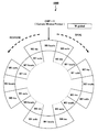
- FIG. 1 is a diagram showing the configuration of a register window type register file.
- the register file 1000 shown in FIG. 1 has one register window W global and eight register windows W0 to W7, and among these, the register windows W0 to W7 are logically connected in a ring shape. .
- Wk local has 8 local registers specific to each register window.
- Wk in has eight in registers (in registers), and Wk out has eight out registers (out registers).
- W global has eight global registers shared by all subroutines.
- Wk out is used to pass arguments to the subroutine called by the routine
- Wk in is used to receive arguments from the parent routine that called the routine.
- register file 1000 WkWin and Wk + 1 out, and Wk out and Wk-1 in are configured to overlap, so at the time of a subroutine call, passing of arguments and securing the registers used for that are fast.
- Can be Wk local is used as a working register set by each subroutine, that is, a child routine called from the parent routine.
- Each subroutine uses one of the eight register windows W0 to W7 at the time of execution.
- the register window Wk (referred to as the current window) used by the subroutine that is being executed corresponds to the two segments clockwise (in the direction of the broken arrow indicated by “SAVE”) each time a subroutine call occurs.
- the subroutine returns, it rotates counterclockwise (in the direction of the broken arrow indicated by “RESTORE”) by the two segments.
- each register window Wk is managed by a register window number (hereinafter referred to as a window number) assigned to each register window Wk.
- a window number k is assigned to the register window Wk.
- the window number k of the register window Wk used by the subroutine being executed is held in CWP (Current Window Pointer).
- the value of CWP is incremented by executing a SAVE instruction or generating a trap, and decremented by executing a RESTORE instruction or returning from a trap by a RETT instruction.
- the value of CWP is “0”, and CWP designates the register window W0.
- an instruction for switching the current window by increasing or decreasing the value of CWP is referred to as a “window switching instruction” in this specification.
- the register file 1000 shown in FIG. 1 has one window Wglobal.
- W global is a register set that stores data shared by all routines.
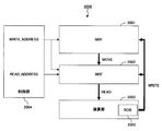
- MRF master register file 2001
- WRF working register file 2002
- calculation unit 2003 calculation unit 2003
- control unit 2004 control unit 2004
- WRF2002 is held as a subset of MRF2001 that holds a copy of one window in MRF2001 indicated by pointer CWP, and data is read from WRF2002. .
- WRF 2002 only holds a copy of the window indicated by the pointer. Since WRF 2002 is smaller than MRF 2001, when reading is performed by supplying READ_ADDRESS, which is a read address, from control unit 2004, data reading can be performed at high speed.
- the calculation unit 2003 includes a rename register ROB2005 to the MRF 2001, and performs renaming of calculation results. Further, the calculation result is written back from ROB 2005 to MRF 2001 and WRF 2002 at the time of commit.
- an arithmetic processing unit having a configuration as shown in FIG. 2 has been devised.
- hardware is provided in that a subset of the MRF that holds a copy of one window in the MRF is provided. costly.
- power is consumed by performing transfer between MRF and WRF.
- the execution order of instructions is not limited to the order of programs, but is executed from instructions that can be processed. Therefore, it is also required to realize the instruction execution order change by overtaking the register window switching instruction.
- an object of the present invention is to reduce hardware costs related to register reading and to eliminate power consumption for work buffers and transfer between buffers in an arithmetic processing unit employing a register window method. Further, in the case of an arithmetic processing unit having an out-of-order execution function, it is necessary to realize a change in instruction execution order by overtaking a register window switching instruction.
- the read portion of the MRF is configured to be controlled in two steps: current window selection and register selection.
- a register selected in the register read port is set in advance for each port so that out-of-order execution is possible.
- the present invention it is possible to reduce the cost of WRF hardware while maintaining the conventional performance. Furthermore, it is possible to reduce power consumption by not using WRF, and to reduce power consumption by eliminating data transfer between MRF and WRF.
- FIG. 3 shows the configuration of the arithmetic processing apparatus of this embodiment that employs the register window method.
- the arithmetic processing unit 0 includes a master register file (MRF) 1, an arithmetic unit 3 and a control unit 4. Compared to the arithmetic processing device 2000 of FIG. 2, the arithmetic processing device 0 shown in FIG. 3 has a configuration that does not include the WRF 2002 that is temporary storage.
- An ROB (renaming register) 5 provided in the calculation unit 3 is a part for renaming the calculation result, and the calculation result is written back to the MRF 1 at the time of commit (write).
- the read-out portion of MRF1 is controlled in two stages, current window selection and register selection.
- the current window selection is controlled by a WINDOW_ADDRESS signal output from the control unit 4.
- the WINDOW_ADDRESS signal is a signal based on the value of CWP (Current Window Pointer).
- Register selection is controlled by a READ_ADDRESS signal output from the control unit 4.
- the register selected by the register read port is set in advance so that it can be executed out of order.
- high-speed data reading to the arithmetic unit 3 is possible without providing temporary storage, and out-of-order execution of instructions subsequent to the SAVE instruction and the RESTORE instruction is possible. .
- Fig. 4 shows the configuration of the register window.
- Fig. 6 shows the locations where out-of-order processing is performed when instructions are pipelined. As shown in Fig. 6, when executing an instruction, each process of Fetch (F), Decode (D), Dispatch (P), Buffer read (B), Execute (x), Update buffer (U), Commit (W) Is executed. As shown in FIG. 6, out-of-order processing (OOO) is performed by Dispatch (P), Buffer ⁇ Read (B), Execute (X), and Update Buffer (U).
- a period during which the SAVE instruction is substantially executed that is, from the Dispatch (“P” in the figure) of the execution process of the SAVE instruction, the Update buffer (in the figure)
- W2 out, W2 in (W1 out) the register group W global, W2 local, W2 out, W1 local, W1 out, W0 out is used to execute the out-of-order execution of the instruction following the SAVE instruction. It must be readable.
- G_PORT global
- L_PORT0 global
- L_PORT1 OUT_PORT0
- OUT_PORT1 OUT_PORT2
- OUT_PORT2 OUT_PORT2
- the W_global register group in G_PORT the W2 local register group in L_PORT0, the W1 local register group in L_PORT1, the W0 out register group in OUT_PORT0, and the W1 in W_OUT_PORT1
- the out register group is assigned to W_out register group for OUT_PORT2.
- the read register group to each port may be made to correspond as shown in FIG. 8 according to the value of CWP.
- a notation delimited by slashes such as “W7 / W1” indicates that the “W7” register group is used in out-of-order execution during execution of the RESTORE instruction, and that in the out-of-order execution during execution of the SAVE instruction.
- the “W1” register group is assigned.
- L_PORT0 and L_PORT1 have local register groups W0 local and W1 local, respectively.
- OUT_PORT0, OUT_PORT1, and OUT_PORT2 are assigned to W0 out, W7 out, and W1 out, respectively.
- L_PORT0 is selected from W (2n) local register group
- L_PORT1 is selected from W (2n + 1) local register group.
- any one of W (2n) out registers is selected for O_PORT0
- any one of W (2n + 1) out registers is selected for O_PORT1
- W (2n) out is selected for O_PORT2.
- any one of the register groups of W (2n + 1) ⁇ ⁇ ⁇ ⁇ out may be selected.
- a register to be read may be selected depending on whether or not the WINDOW_ADDRESS signal based on the value of CWP, the SAVE instruction, and the RESTORE instruction are being executed.
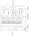
- FIG. 9 is a diagram showing a configuration example of a register window system in the arithmetic processing unit 0 of the present embodiment shown in FIG. 3, and
- FIG. 10 is a diagram showing a configuration example of a conventional register window system.
- each set of 8 register values output from four local register groups indicated by W0 local, W2 local, W4 local, and W6 local, One set is selected by the selector 904 and output to the L_PORT0 port.
- Each set of eight register values output from the four local register groups indicated by W1 local, W3 local, W5 local, and W7 local is selected by the selector 905 and output to the L_PORT1 port.
- Each set of 8 register values output from the four local register groups indicated by W0 out, W2 out, W4 out, and W6 out is selected by the selector 905 and output to the OUT_PORT0 port.
- any pair is selected by the selectors 905 and 907 and output to the OUT_PORT2 port.
- Each set of 8 register values output from the four local register groups indicated by W1 out, W3 out, W5 out, and W7 out is selected by the selector 906 and output to the OUT_PORT1 port.
- one of the pairs is selected by the selectors 906 and 907 and output to the OUT_PORT2 port.
- a set of 8 register values output from the global register group indicated by GL is output to the G_PORT port.
- L_PORT0, L_PORT1, OUT_PORT0, OUT_PORT1, OUT_PORT2, and G_PORT are output to the 6 ports, each of which has 8 register values. Data). Note that “48: 1” in the selector 908 means that one register value is selectively output from 48 register values.
- the selector 903 is operated according to the operation algorithm of the rules 1 to 6 based on the WINDOW_ADDRESS signal based on the value of CWP and the execution state of the SAVE instruction or RESTORE instruction.
- ⁇ 907 operate to select each register group output.
- This operation algorithm can be configured by a simple logic circuit.
- the READ_ADDRESS signal supplied to the selector 908 may be a signal for selecting one register value from 48 register values.
- the WRITE_ADDRESS signal controls the selector 902 to write WRITE_DATA (write data) to each register group.
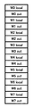
- the master register file (MRF) 1001 is represented by eight local register groups indicated by W0 local to W7 local and W0 out to W7 out. 8 out register groups and a global register group indicated by GL.
- the eight in-register groups W0Win to W7 in are shared with the eight out-register groups W7 out and W0 out to W6 out, respectively.
- the working register file (WRF) 1002 is an 8-register value of a selected set of global registers output from the MRF 1001 at a certain CWP value in the MRF 1001, and an 8-register value of a selected set of local registers.
- G register group 1005, L register group 1006, IN holding 8 register values of the selected in-register group ( out register group) and 8 register values of the selected one out-register group, respectively
- the G / L register group 1003 that temporarily holds the current eight register output values of the local register groups W0 ⁇ local to W7 local from the MRF 1001 or the global register group GL
- Out register group from MRF1001 Select the IO register group 1004 that temporarily holds the current 8-register output value of any of W0 out to W7 ⁇ out, the G / L register group 1003, the IO register group 1004, or WRITE_DATA (write data) to select 1005 to 1008
- a selector 1010 for selecting one register value of 6 register groups of register groups 1003 to 1008, that is, 6 ⁇ 8 48 register groups, and outputting it as READ_DATA (read data)
- “48: 1” in the selector 1010 means that one register is selected from the 48 register group.
- read data corresponding to the current CWP value in the MRF 1001 is obtained from the output of each register group in the MRF 1001 and the G / L register group 1003 and the IO register. It is always held in the register groups 1005 to 1008 in the WRF 1002 via the group 1004 and the selector 1009.
- the current write data in the MRF 1001 is held in the register groups 1005 to 1008 in the WRF 1002 via the selector 1009 in the MRF 1001.
- the data indicated by the current CWP can be read at high speed as READ_DATA simply by supplying the selector 1010 with an address signal for selecting one of the register groups 1005 to 1008 or 1003 and 1004 as READ_ADDRESS. Become. In consideration of out-of-order execution or the like, the selector 1010 is configured to be able to select the outputs of the register groups 1003 and 1004 that are the current outputs of the MRF 1001.
- a first local register read port (L_PORT0) that selects a register from a group of local registers with an even window number based on the current window number, and a local register with an odd window number based on the current window number
- a second local register read port (L_PORT1) for selecting a register from the group
- a first out register read port (OUT_PORT0) for selecting a register from an out register group having an even window number based on the current window number
- a current A second out register read port (OUT_PORT1) that selects a register from an out register group having an odd window number based on the window number
- a third that selects a register from the out register group based on the current window number Register selection is performed by the out-register reading port (OUT_PORT2).
- the arithmetic processing unit can realize high-speed reading from the register without using the WRF that is temporary storage, and can execute out-of-order execution of the instruction subsequent to the window switching instruction. Is also possible.
- FIG. 11 shows an example of the configuration of the information processing apparatus.
- the information processing apparatus 110 includes a cache control unit 114 including an arithmetic unit 112, a memory 111, an instruction control unit 113, and a cache 115.
- the arithmetic processing device 0 described above corresponds to the arithmetic unit 112.
- the control unit 4 shown in FIG. 3 corresponds to the calculation control unit 116, the calculation unit 3 corresponds to the calculation unit 118, and MRF 1 corresponds to the register unit 117.
- the information processing apparatus 110 is configured by adopting the above-described arithmetic processing apparatus 0, the hardware cost can be reduced and the power consumption can also be reduced.
- the present invention is not limited to this, and various configurations or shapes can be made without departing from the gist of the present embodiment. It goes without saying that it can be taken.
Landscapes
- Engineering & Computer Science (AREA)
- Software Systems (AREA)
- Theoretical Computer Science (AREA)
- Physics & Mathematics (AREA)
- General Engineering & Computer Science (AREA)
- General Physics & Mathematics (AREA)
- Executing Machine-Instructions (AREA)
Abstract
Description
図1に示すレジスタファイル1000は、1本のレジスタウィンドウW globalと、8本のレジスタウィンドウW0~W7を有し、これらのうち、レジスタウィンドウW0~W7は論理的にリング状に連結されている。各レジスタウィンドウWk(k=0~7)はそれぞれ、、Wk out、Wk in、およびWk localの3種類のセグメントを備えている。これら3種類のセグメントは、いずれも、8個のレジスタから構成されている。Wk localは各レジスタウィンドウ固有の8個のローカルレジスタを備えている。Wk inは8個のinレジスタ(インレジスタ)を備え、Wk outは8個のoutレジスタ(アウトレジスタ)を備えている。また、W globalは、全てのサブルーチンで共用される8個のグローバルレジスタを備えている。 FIG. 1 is a diagram showing the configuration of a register window type register file.
The
各レジスタウィンドウWkは24個(=8×3)のレジスタを備えており、レジスタウィンドウW globalは8個のレジスタを備えている。これらのレジスタのうち、Wk inとWk outのレジスタが64個(=8×8)オーバーラップしているので、レジスタファイル1000が備えるレジスタの総数は、136個(=24×8+8-64)である。プロセッサの演算器がサブルーチンを実行するためには、レジスタファイル1000のそれら全てのレジスタにデータを読み書きできる必要がある。 The
Each register window Wk has 24 (= 8 × 3) registers, and the register window W global has 8 registers. Among these registers, 64 registers (= 8 × 8) overlap in Wk in and Wk out, so the total number of registers included in the
図3に、レジスタウィンドウ方式を採用する本実施形態の演算処理装置の構成を示す。 Hereinafter, an example of an embodiment that realizes high-speed reading from a register in an arithmetic processing apparatus having a register window type register file will be described with reference to the drawings.
FIG. 3 shows the configuration of the arithmetic processing apparatus of this embodiment that employs the register window method.
図1に示したように、MRF1のレジスタは、Wk local, Wk in, Wk outがそれぞれ8レジスタずつ、8ウィンドウ分(k=0~7)あり、またそれらとは別にW globalが8レジスタある。W globalレジスタはすべてのウィンドウで共通であり、ウィンドウ切り替えで影響がないため、以降の説明からは省略することとする。 Hereinafter, the configuration of the
As shown in FIG. 1, the registers of MRF1 have 8 registers for Wk local, Wk in, and Wk out for 8 windows (k = 0 to 7), and there are 8 registers for W global separately. . Since the W global register is common to all windows and does not affect the window switching, it will be omitted from the following description.
図8において、例えば「W7/W1」のようなスラッシュで区切られた表記は、RESTORE命令実行時のアウトオブオーダ実行においては「W7」レジスタ群が、SAVE命令実行時のアウトオブオーダ実行においては「W1」レジスタ群が割り当てられることを示している。 In summary, the read register group to each port may be made to correspond as shown in FIG. 8 according to the value of CWP.
In FIG. 8, for example, a notation delimited by slashes such as “W7 / W1” indicates that the “W7” register group is used in out-of-order execution during execution of the RESTORE instruction, and that in the out-of-order execution during execution of the SAVE instruction. The “W1” register group is assigned.
L_PORT0 = W2n local
L_PORT1 = *(don’t careの意)
OUT_PORT0 = W2n out
OUT_PORT1 = W(2n-1) out
OUT_PORT2 = *(don’t careの意)
ルール2 CWP=2n+1の時(SAVE・RESTORE命令実行中以外):
L_PORT0 = *(don’t careの意)
L_PORT1 = W(2n+1) local
OUT_PORT0 = W2n out
OUT_PORT1 = WP(2n+1) out
OUT_PORT2 = *(don’t careの意)
ルール3 CWP=2nの時(SAVE命令実行中):
L_PORT0 = W2n local
L_PORT1 = W(2n+1) local
OUT_PORT0 = W2n out
OUT_PORT1 = W(2n-1) out
OUT_PORT2 = W(2n+1) out
ルール4 CWP=2n+1の時(SAVE命令実行中):
L_PORT0 = W(2n+2) local
L_PORT1 = W(2n+1) local
OUT_PORT0 = W2n out
OUT_PORT1 = W(2n+1) out
OUT_PORT2 = W(2n+2) out
ルール5 CWP=2nの時(RESTORE命令実行中):
L_PORT0 = W2n local
L_PORT1 = W(2n-1) local
OUT_PORT0 = W2n out
OUT_PORT1 = W(2n-1) out
OUT_PORT2 = W(2n-2) out
ルール6 CWP=2n+1の時(RESTORE命令実行中):
L_PORT0 = W2n local
L_PORT1 = W(2n+1) local
OUT_PORT0 = W2n out
OUT_PORT1 = W(2n+1) out
OUT_PORT2 = W(2n-2) out
L_PORT0 = W2n local
L_PORT1 = * (don't care)
OUT_PORT0 = W2n out
OUT_PORT1 = W (2n-1) out
OUT_PORT2 = * (don't care)
L_PORT0 = * (don't care)
L_PORT1 = W (2n + 1) local
OUT_PORT0 = W2n out
OUT_PORT1 = WP (2n + 1) out
OUT_PORT2 = * (don't care)
L_PORT0 = W2n local
L_PORT1 = W (2n + 1) local
OUT_PORT0 = W2n out
OUT_PORT1 = W (2n-1) out
OUT_PORT2 = W (2n + 1) out
L_PORT0 = W (2n + 2) local
L_PORT1 = W (2n + 1) local
OUT_PORT0 = W2n out
OUT_PORT1 = W (2n + 1) out
OUT_PORT2 = W (2n + 2) out
L_PORT0 = W2n local
L_PORT1 = W (2n-1) local
OUT_PORT0 = W2n out
OUT_PORT1 = W (2n-1) out
OUT_PORT2 = W (2n-2) out
L_PORT0 = W2n local
L_PORT1 = W (2n + 1) local
OUT_PORT0 = W2n out
OUT_PORT1 = W (2n + 1) out
OUT_PORT2 = W (2n-2) out
L_PORT0、L_PORT1、OUT_PORT0、OUT_PORT1、OUT_PORT2 、およびG_PORTの6ポートに出力されたそれぞれ8レジスタ値からなる合計8×6=48レジスタ値は、セレクタ908によって1つのレジスタ値が選択されて、READ_DATA(読出しデータ)として出力される。なお、セレクタ908中の「48:1」は、48レジスタ値から1レジスタ値を選択出力することを意味する。 A set of 8 register values output from the global register group indicated by GL is output to the G_PORT port.
L_PORT0, L_PORT1, OUT_PORT0, OUT_PORT1, OUT_PORT2, and G_PORT are output to the 6 ports, each of which has 8 register values. Data). Note that “48: 1” in the
ここまで、本実施の形態の演算処理装置0の構成を詳細に説明した。上述したように、本実施の形態の演算処理装置0では、図3のMRF1の読み出し部分をCWPの値、すなわちカレントウィンドウの番号によって選択するカレントウィンドウ選択(WINDOW_ADDRESS)と、読み出しアドレスに相当するREAD_ADDRESSにより読み出しレジスタを選択する2段階で制御する。カレントウィンドウ選択においては、カレントウィンドウ番号に基づいてウィンドウ番号が偶数のローカルレジスタ群からレジスタを選択する第1のローカルレジスタ読出しポート(L_PORT0)と、カレントウィンドウ番号に基づいてウィンドウ番号が奇数のローカルレジスタ群からレジスタを選択する第2のローカルレジスタ読出しポート(L_PORT1)と、カレントウィンドウ番号に基づいてウィンドウ番号が偶数のアウトレジスタ群からレジスタを選択する第1のアウトレジスタ読出しポート(OUT_PORT0)と、カレントウィンドウ番号に基づいてウィンドウ番号が奇数のアウトレジスタ群からレジスタを選択する第2のアウトレジスタ読出しポート(OUT_PORT1)と、カレントウィンドウ番号に基づいてアウトレジスタ群からレジスタを選択する第3のアウトレジスタ読出しポート(OUT_PORT2)によりレジスタの選択が行われる。 As described above, if the configuration of this embodiment shown in FIG. 9 is compared with the configuration of the conventional example shown in FIG. 10, the superiority of this embodiment is clear.
Up to this point, the configuration of the
図11に情報処理装置の構成の一例を示す。情報処理装置110は、演算ユニット112、メモリ111、命令制御ユニット113、キャッシュ115を含むキャッシュ制御ユニット114を有する。上述した演算処理装置0は演算ユニット112に対応する。図3に示した制御部4が演算制御部116に、演算部3が演算部118、MRF1がレジスタ部117に対応する。 Although an example of the present embodiment has been described above with reference to the drawings, the present invention can also be configured as an information processing device including the arithmetic processing device described above.
FIG. 11 shows an example of the configuration of the information processing apparatus. The information processing apparatus 110 includes a cache control unit 114 including an arithmetic unit 112, a memory 111, an instruction control unit 113, and a cache 115. The
以上のように、本発明の実施の形態の一例について詳細に説明したが、本発明はこれに限定されるものではなく、本実施の形態の要旨を逸脱しない範囲内で様々の構成または形状をとることができることは言うまでもない。 Since the information processing apparatus 110 is configured by adopting the above-described
As described above, an example of an embodiment of the present invention has been described in detail. However, the present invention is not limited to this, and various configurations or shapes can be made without departing from the gist of the present embodiment. It goes without saying that it can be taken.
Claims (6)
- 演算処理を行う演算部と、
各々N本のレジスタを備えたK枚のウィンドウを有し、各ウィンドウを構成する一部のレジスタは両隣のウィンドウを構成するレジスタと共有され、該共有部分をサブルーチン呼び出し時の引数の引き渡しに使用するように構成されたレジスタウィンドウと、前記K枚のウィンドウのうちの1枚を選択するカレントウィンドウ選択手段と、読み出しアドレスにより読み出しレジスタを選択するレジスタ選択手段と、を備えるレジスタファイルと、
前記レジスタファイルにおいてカレントウィンドウ選択手段においてウィンドウを選択するためのウィンドウアドレス信号を出力する制御部と、
を備えることを特徴とする演算処理装置。 An arithmetic unit for performing arithmetic processing;
There are K windows each with N registers, and some registers that make up each window are shared with the registers that make up the windows on both sides, and this shared part is used to pass arguments when calling subroutines A register file comprising a register window configured to, a current window selecting unit that selects one of the K windows, and a register selecting unit that selects a read register according to a read address;
A control unit for outputting a window address signal for selecting a window in the current window selection means in the register file;
An arithmetic processing apparatus comprising: - 前記カレントウィンドウ選択手段は、
前記ウィンドウアドレス信号に基づいて、前記サブルーチンの作業用レジスタであるローカルレジスタのうち、ウィンドウ番号が偶数のローカルレジスタ群からレジスタを選択する第1のローカルレジスタ読出しポートと、
前記ウィンドウアドレス信号に基づいて、前記サブルーチンの作業用レジスタであるローカルレジスタのうち、ウィンドウ番号が奇数のローカルレジスタ群からレジスタを選択する第2のローカルレジスタ読出しポートと、
前記ウィンドウアドレス信号に基づいて、前記サブルーチンの呼出し時の引数の引き渡しに用いられるアウトレジスタのうち、ウィンドウ番号が偶数のアウトレジスタ群からレジスタを選択する第1のアウトレジスタ読出しポートと、
前記ウィンドウアドレス信号に基づいて、前記サブルーチンの呼出し時の引数の引き渡しに用いられるアウトレジスタのうち、ウィンドウ番号が奇数のアウトレジスタ群からレジスタを選択する第2のアウトレジスタ読出しポートと、
前記ウィンドウアドレス信号に基づいて、前記サブルーチンの呼出し時の引数の引き渡しに用いられるアウトレジスタ群からレジスタを選択する第3のアウトレジスタ読出しポートと、
を備えることを特徴とする請求項1記載の演算処理装置。 The current window selection means includes:
A first local register read port that selects a register from a local register group having an even window number among local registers that are working registers of the subroutine based on the window address signal;
A second local register read port that selects a register from a local register group having an odd window number among local registers that are working registers of the subroutine based on the window address signal;
A first out register read port for selecting a register from an out register group having an even window number among out registers used for passing an argument at the time of calling the subroutine based on the window address signal;
A second out-register read port for selecting a register from an out-register group having an odd window number among out-registers used for passing an argument when calling the subroutine based on the window address signal;
A third out register read port for selecting a register from an out register group used for passing an argument when calling the subroutine based on the window address signal;
The arithmetic processing apparatus according to claim 1, further comprising: - 演算処理を行う演算部と、
複数のレジスタから構成されるレジスタファイルで、該レジスタファイルを各々N本のレジスタを備えたK枚のウィンドウに分割し、各ウィンドウは各々一部のレジスタを両隣のウィンドウと共有し、該共有部分をサブルーチン呼び出し時の引数の引き渡しに使用するように構成されたレジスタウィンドウを備えるレジスタファイルであって、前記K枚のウィンドウのうちの1枚を選択するカレントウィンドウ選択手段と、読み出しアドレスにより読み出しレジスタを選択するレジスタ選択手段と、を備えるレジスタファイルと、
前記レジスタファイルにおいてカレントウィンドウ選択手段においてウィンドウを選択するためのウィンドウアドレス信号を出力する制御部と、
を含む演算処理装置を有することを特徴とする情報処理装置。 An arithmetic unit for performing arithmetic processing;
A register file composed of a plurality of registers, and the register file is divided into K windows each having N registers, and each window shares a part of a register with adjacent windows, and the shared part Is a register file having a register window configured to be used for passing an argument when calling a subroutine, and a current window selecting means for selecting one of the K windows and a read register by a read address A register selection means for selecting a register file, and
A control unit for outputting a window address signal for selecting a window in the current window selection means in the register file;
An information processing apparatus comprising an arithmetic processing apparatus including: - 前記カレントウィンドウ選択手段は、
前記ウィンドウアドレス信号に基づいて、前記サブルーチンの作業用レジスタであるローカルレジスタのうち、ウィンドウ番号が偶数のローカルレジスタ群からレジスタを選択する第1のローカルレジスタ読出しポートと、
前記ウィンドウアドレス信号に基づいて、前記サブルーチンの作業用レジスタであるローカルレジスタのうち、ウィンドウ番号が奇数のローカルレジスタ群からレジスタを選択する第2のローカルレジスタ読出しポートと、
前記ウィンドウアドレス信号に基づいて、前記サブルーチンの呼出し時の引数の引き渡しに用いられるアウトレジスタのうち、ウィンドウ番号が偶数のアウトレジスタ群からレジスタを選択する第1のアウトレジスタ読出しポートと、
前記ウィンドウアドレス信号に基づいて、前記サブルーチンの呼出し時の引数の引き渡しに用いられるアウトレジスタのうち、ウィンドウ番号が奇数のアウトレジスタ群からレジスタを選択する第2のアウトレジスタ読出しポートと、
前記ウィンドウアドレス信号に基づいて、前記サブルーチンの呼出し時の引数の引き渡しに用いられるアウトレジスタ群からレジスタを選択する第3のアウトレジスタ読出しポートと、
を備えることを特徴とする請求項3記載の情報処理装置。 The current window selection means includes:
A first local register read port that selects a register from a local register group having an even window number among local registers that are working registers of the subroutine based on the window address signal;
A second local register read port that selects a register from a local register group having an odd window number among local registers that are working registers of the subroutine based on the window address signal;
A first out register read port for selecting a register from an out register group having an even window number among out registers used for passing an argument at the time of calling the subroutine based on the window address signal;
A second out-register read port for selecting a register from an out-register group having an odd window number among out-registers used for passing an argument when calling the subroutine based on the window address signal;
A third out register read port for selecting a register from an out register group used for passing an argument when calling the subroutine based on the window address signal;
The information processing apparatus according to claim 3, further comprising: - 複数のレジスタから構成されるレジスタファイルで、該レジスタファイルを各々N本のレジスタを備えたK枚のウィンドウに分割し、各ウィンドウは各々一部のレジスタを両隣のウィンドウと共有し、該共有部分をサブルーチン呼び出し時の引数の引き渡しに使用するように構成されたレジスタウィンドウを備えるレジスタファイルの読み出し方法であって、
前記K枚のウィンドウのうちの1枚を選択する第1のステップと、
前記選択されたウィンドウレジスタから、読み出しアドレスにより読み出しレジスタを選択する第2のステップと、
からレジスタを読み出すことを特徴とするレジスタファイルの読み出し方法。 A register file composed of a plurality of registers, and the register file is divided into K windows each having N registers, and each window shares a part of a register with adjacent windows, and the shared part A method for reading a register file comprising a register window configured to be used for passing arguments when calling a subroutine,
A first step of selecting one of the K windows;
A second step of selecting a read register from the selected window register by a read address;
A method for reading a register file, wherein the register is read from the register. - 前記第1のステップにおいて、前記K枚のウィンドウをそれぞれ識別するためのウィンドウ番号のうち1つがカレントウィンドウ番号として選択され、
前記カレントウィンドウ番号に基づいて、第1のローカルレジスタ読出しポートにおいて、前記サブルーチンの作業用レジスタであるローカルレジスタのうち、ウィンドウ番号が偶数のローカルレジスタ群からレジスタを選択し、
前記カレントウィンドウ番号に基づいて、第2のローカルレジスタ読出しポートにおいて、前記サブルーチンの作業用レジスタであるローカルレジスタのうち、ウィンドウ番号が奇数のローカルレジスタ群からレジスタを選択し、
前記カレントウィンドウ番号に基づいて、第1のアウトレジスタ読出しポートにおいて、前記サブルーチンの呼出し時の引数の引き渡しに用いられるアウトレジスタのうち、ウィンドウ番号が偶数のアウトレジスタ群からレジスタを選択し、
前記カレントウィンドウ番号に基づいて、第2のアウトレジスタ読出しポートにおいて、前記サブルーチンの呼出し時の引数の引き渡しに用いられるアウトレジスタのうち、ウィンドウ番号が奇数のアウトレジスタ群からレジスタを選択し、
前記カレントウィンドウ番号に基づいて、前記サブルーチンの呼出し時の引数の引き渡しに用いられるアウトレジスタ群からレジスタを選択する、
ことを特徴とする請求項5記載のレジスタファイルの読み出し方法。 In the first step, one of window numbers for identifying each of the K windows is selected as a current window number;
Based on the current window number, in the first local register read port, among the local registers that are working registers of the subroutine, a register is selected from a local register group having an even window number;
Based on the current window number, the second local register read port selects a register from the local register group having an odd window number among the local registers that are working registers of the subroutine,
Based on the current window number, in the first out register read port, a register is selected from an out register group having an even window number among out registers used for passing an argument when calling the subroutine,
Based on the current window number, in the second out-register read port, a register is selected from an out-register group having an odd window number among out-registers used for passing an argument when calling the subroutine,
Based on the current window number, a register is selected from an out-register group used for passing an argument when calling the subroutine.
6. A method for reading a register file according to claim 5, wherein:
Priority Applications (6)
| Application Number | Priority Date | Filing Date | Title |
|---|---|---|---|
| PCT/JP2008/002172 WO2010016097A1 (en) | 2008-08-08 | 2008-08-08 | Processing unit |
| KR1020117002117A KR101244074B1 (en) | 2008-08-08 | 2008-08-08 | Processing unit |
| JP2010523656A JP5229321B2 (en) | 2008-08-08 | 2008-08-08 | Arithmetic processing unit |
| EP08790429.8A EP2325744B1 (en) | 2008-08-08 | 2008-08-08 | Processing unit |
| CN200880130631.8A CN102112965B (en) | 2008-08-08 | 2008-08-08 | Operation processing unit |
| US13/017,665 US8539208B2 (en) | 2008-08-08 | 2011-01-31 | Register file having multiple windows and a current window pointer |
Applications Claiming Priority (1)
| Application Number | Priority Date | Filing Date | Title |
|---|---|---|---|
| PCT/JP2008/002172 WO2010016097A1 (en) | 2008-08-08 | 2008-08-08 | Processing unit |
Related Child Applications (1)
| Application Number | Title | Priority Date | Filing Date |
|---|---|---|---|
| US13/017,665 Continuation US8539208B2 (en) | 2008-08-08 | 2011-01-31 | Register file having multiple windows and a current window pointer |
Publications (1)
| Publication Number | Publication Date |
|---|---|
| WO2010016097A1 true WO2010016097A1 (en) | 2010-02-11 |
Family
ID=41663327
Family Applications (1)
| Application Number | Title | Priority Date | Filing Date |
|---|---|---|---|
| PCT/JP2008/002172 WO2010016097A1 (en) | 2008-08-08 | 2008-08-08 | Processing unit |
Country Status (6)
| Country | Link |
|---|---|
| US (1) | US8539208B2 (en) |
| EP (1) | EP2325744B1 (en) |
| JP (1) | JP5229321B2 (en) |
| KR (1) | KR101244074B1 (en) |
| CN (1) | CN102112965B (en) |
| WO (1) | WO2010016097A1 (en) |
Cited By (1)
| Publication number | Priority date | Publication date | Assignee | Title |
|---|---|---|---|---|
| EP2821917A1 (en) | 2013-07-04 | 2015-01-07 | Fujitsu Limited | Processing device and control method of processing device |
Families Citing this family (1)
| Publication number | Priority date | Publication date | Assignee | Title |
|---|---|---|---|---|
| US11144364B2 (en) * | 2019-01-25 | 2021-10-12 | International Business Machines Corporation | Supporting speculative microprocessor instruction execution |
Citations (2)
| Publication number | Priority date | Publication date | Assignee | Title |
|---|---|---|---|---|
| JPH0520010A (en) * | 1991-07-16 | 1993-01-29 | Matsushita Electric Ind Co Ltd | Register file |
| JPH05282147A (en) * | 1992-02-03 | 1993-10-29 | Matsushita Electric Ind Co Ltd | Register file |
Family Cites Families (5)
| Publication number | Priority date | Publication date | Assignee | Title |
|---|---|---|---|---|
| US5179682A (en) * | 1990-05-15 | 1993-01-12 | Sun Microsystems, Inc. | Method and apparatus for improved current window cache with switchable address in, out, and local cache registers |
| JP3737755B2 (en) * | 2001-12-28 | 2006-01-25 | 富士通株式会社 | Register file by register window method and control method thereof |
| JP5028774B2 (en) * | 2005-09-22 | 2012-09-19 | 富士通株式会社 | Arithmetic processing device, information processing device, and register file control method |
| JP5130757B2 (en) * | 2007-03-16 | 2013-01-30 | 富士通株式会社 | Arithmetic processing device and control method of arithmetic processing device |
| JP5282147B2 (en) | 2010-02-15 | 2013-09-04 | 株式会社日立製作所 | Cryptographic communication system and transmitter and receiver used therefor |
-
2008
- 2008-08-08 EP EP08790429.8A patent/EP2325744B1/en active Active
- 2008-08-08 WO PCT/JP2008/002172 patent/WO2010016097A1/en active Application Filing
- 2008-08-08 CN CN200880130631.8A patent/CN102112965B/en active Active
- 2008-08-08 KR KR1020117002117A patent/KR101244074B1/en active IP Right Grant
- 2008-08-08 JP JP2010523656A patent/JP5229321B2/en active Active
-
2011
- 2011-01-31 US US13/017,665 patent/US8539208B2/en active Active
Patent Citations (2)
| Publication number | Priority date | Publication date | Assignee | Title |
|---|---|---|---|---|
| JPH0520010A (en) * | 1991-07-16 | 1993-01-29 | Matsushita Electric Ind Co Ltd | Register file |
| JPH05282147A (en) * | 1992-02-03 | 1993-10-29 | Matsushita Electric Ind Co Ltd | Register file |
Non-Patent Citations (2)
| Title |
|---|
| CATANZARO B.J.: "The SPARC Technical Papers.", SPRINGER VERLAG, 1991, pages 60 - 61, 235 - 237, XP008142773 * |
| See also references of EP2325744A4 * |
Cited By (1)
| Publication number | Priority date | Publication date | Assignee | Title |
|---|---|---|---|---|
| EP2821917A1 (en) | 2013-07-04 | 2015-01-07 | Fujitsu Limited | Processing device and control method of processing device |
Also Published As
| Publication number | Publication date |
|---|---|
| CN102112965B (en) | 2015-06-17 |
| US8539208B2 (en) | 2013-09-17 |
| EP2325744B1 (en) | 2022-08-03 |
| JPWO2010016097A1 (en) | 2012-01-12 |
| KR20110034654A (en) | 2011-04-05 |
| EP2325744A4 (en) | 2011-08-10 |
| EP2325744A1 (en) | 2011-05-25 |
| JP5229321B2 (en) | 2013-07-03 |
| CN102112965A (en) | 2011-06-29 |
| KR101244074B1 (en) | 2013-03-18 |
| US20110125988A1 (en) | 2011-05-26 |
Similar Documents
| Publication | Publication Date | Title |
|---|---|---|
| US7457938B2 (en) | Staggered execution stack for vector processing | |
| US8140829B2 (en) | Multithreaded processor and method for switching threads by swapping instructions between buffers while pausing execution | |
| US20050251645A1 (en) | Method and apparatus for staggering execution of an instruction | |
| US6463525B1 (en) | Merging single precision floating point operands | |
| JP2911278B2 (en) | Processor | |
| JP2004158018A (en) | Layout system for semiconductor floor plan of register renaming circuit | |
| JP2012141810A (en) | Arithmetic processing unit and arithmetic processing method | |
| US7343478B2 (en) | Register window system and method that stores the next register window in a temporary buffer | |
| GB2451845A (en) | Executing multiple threads using a shared register | |
| JP5130757B2 (en) | Arithmetic processing device and control method of arithmetic processing device | |
| US7093110B2 (en) | Register file in the register window system and controlling method thereof | |
| JP5229321B2 (en) | Arithmetic processing unit | |
| US7143268B2 (en) | Circuit and method for instruction compression and dispersal in wide-issue processors | |
| EP1221648A1 (en) | Bypass circuitry for use in a pipelined processor | |
| JP5145659B2 (en) | Vector renaming method and vector computer | |
| KR100636596B1 (en) | Parallel Data Path Architecture for High Energy Efficient | |
| JP2004038751A (en) | Processor and instruction control method | |
| JP2008242947A (en) | Semiconductor device | |
| JP2000231488A (en) | Processor | |
| US20240118891A1 (en) | Processor | |
| JP3771682B2 (en) | Vector processing equipment | |
| JP2023088443A (en) | Arithmetic processing device and arithmetic processing method | |
| JP6307975B2 (en) | Arithmetic processing device and control method of arithmetic processing device | |
| JP4703735B2 (en) | Compiler, code generation method, code generation program | |
| JPH1074145A (en) | Instruction supplying device |
Legal Events
| Date | Code | Title | Description |
|---|---|---|---|
| WWE | Wipo information: entry into national phase |
Ref document number: 200880130631.8 Country of ref document: CN |
|
| 121 | Ep: the epo has been informed by wipo that ep was designated in this application |
Ref document number: 08790429 Country of ref document: EP Kind code of ref document: A1 |
|
| WWE | Wipo information: entry into national phase |
Ref document number: 2010523656 Country of ref document: JP |
|
| ENP | Entry into the national phase |
Ref document number: 20117002117 Country of ref document: KR Kind code of ref document: A |
|
| WWE | Wipo information: entry into national phase |
Ref document number: 2008790429 Country of ref document: EP |
|
| NENP | Non-entry into the national phase |
Ref country code: DE |