WO2010010605A1 - ランプ点灯回路及びそれを備えた電子機器 - Google Patents
ランプ点灯回路及びそれを備えた電子機器 Download PDFInfo
- Publication number
- WO2010010605A1 WO2010010605A1 PCT/JP2008/063116 JP2008063116W WO2010010605A1 WO 2010010605 A1 WO2010010605 A1 WO 2010010605A1 JP 2008063116 W JP2008063116 W JP 2008063116W WO 2010010605 A1 WO2010010605 A1 WO 2010010605A1
- Authority
- WO
- WIPO (PCT)
- Prior art keywords
- lamps
- circuit
- lamp
- series
- voltage
- Prior art date
- Legal status (The legal status is an assumption and is not a legal conclusion. Google has not performed a legal analysis and makes no representation as to the accuracy of the status listed.)
- Ceased
Links
Images


Classifications
-
- H—ELECTRICITY
- H05—ELECTRIC TECHNIQUES NOT OTHERWISE PROVIDED FOR
- H05B—ELECTRIC HEATING; ELECTRIC LIGHT SOURCES NOT OTHERWISE PROVIDED FOR; CIRCUIT ARRANGEMENTS FOR ELECTRIC LIGHT SOURCES, IN GENERAL
- H05B39/00—Circuit arrangements or apparatus for operating incandescent light sources
- H05B39/04—Controlling
-
- H—ELECTRICITY
- H05—ELECTRIC TECHNIQUES NOT OTHERWISE PROVIDED FOR
- H05B—ELECTRIC HEATING; ELECTRIC LIGHT SOURCES NOT OTHERWISE PROVIDED FOR; CIRCUIT ARRANGEMENTS FOR ELECTRIC LIGHT SOURCES, IN GENERAL
- H05B47/00—Circuit arrangements for operating light sources in general, i.e. where the type of light source is not relevant
- H05B47/10—Controlling the light source
Definitions
- the present invention relates to a lamp lighting circuit for lighting a lamp including a filament and an electronic apparatus including the lamp lighting circuit.
- a lamp used for lighting an in-vehicle device as an electronic device changes the luminance of the lamp because the applied voltage of the lamp changes due to the fluctuation of the battery voltage due to the running or stopping of the vehicle. Therefore, in order to remove the influence of fluctuations in the battery voltage, the lamp applied voltage is stabilized and lit using a constant voltage circuit.
- the battery voltage is normally 12V, and the voltage stabilized by the constant voltage circuit is preferably set to a setting value of 10V or less assuming that the battery voltage is reduced.
- the applied current is set low and the applied current is set to be large. Since the lamp is advantageous, generally a lamp having a characteristic of about 8V is often used.
- the output voltage of the constant voltage circuit is set to about 8V.
- many lamps used for illumination of in-vehicle devices are in use in order to ensure brightness, prevent variation, expand the area to be illuminated, and the like. Therefore, there is a problem that the loss of the constant voltage circuit for driving the lamp increases.
- the loss of the constant voltage circuit can be improved by changing the lamp used, for example, from a voltage 8V product to a 10V product. In this case, there is a problem that the filament diameter of the lamp is reduced and the earthquake resistance and the lighting life are reduced.
- a method has been used in which a lamp with a low applied voltage is used to ensure earthquake resistance and life, and the applied voltage is increased by connecting them in series. Reduce the loss by setting the voltage setting value of the constant voltage circuit to a value that increases the output voltage as long as the conditions for suppressing the loss of the constant voltage power supply (such as the reduced voltage that causes flickering) are allowed. Can do. Specifically, the circuit 100 shown in FIG. 1 is used.
- a circuit 100 shown in FIG. 1 includes a battery 101, a constant voltage circuit 102, and lamps L11 to L16.
- the circuit S12 and the circuit S13 in which the lamps L15 and L16 are connected in series are connected in parallel, and the voltage of the battery 101 is stabilized and supplied to each circuit S11 to S13 by the constant voltage circuit 102. is doing.
- Patent Document 1 As a method of removing the brightness unevenness of the lamp, a plurality of lamp lighting methods described in Patent Document 1 have been proposed. In the plurality of lamp lighting methods described in Patent Document 1, the brightness unevenness of the lamp is removed by driving each lamp with a constant current circuit set to the minimum value of the rated current. Japanese Patent Laid-Open No. 10-284259
- the present invention provides a lamp lighting circuit capable of eliminating uneven brightness at low cost and suppressing variation in lamp life when a plurality of circuits in which lamps are connected in series are connected in parallel. It is an object to provide an electronic device provided.
- a lamp lighting circuit according to claim 1 is a lamp lighting circuit in which a plurality of circuits in which lamps having the same characteristic provided with a filament are connected in series are connected in parallel. It is characterized in that voltage points having the same potential with respect to the reference potential of the connected circuit are connected to each other.
- Lamp lighting circuit 3 Constant voltage circuit L1 to L9 Lamp S1 to S3 Series circuit (Circuit of lamps connected in series) A to F Intermediate point (Voltage point with the same potential as the reference potential)
- the lamp lighting circuit according to one embodiment of the present invention is configured with the same potential with respect to the reference potential because voltage points that are set to the same potential with respect to the reference potential of each circuit in which the lamps are connected in series are connected to each other.
- the combined resistance values of the filaments of the lamp groups can be made substantially the same, and the voltages applied to these lamp groups are also almost the same. Accordingly, since a voltage with little variation is applied to each lamp, luminance unevenness is eliminated, and variation in lifetime can be suppressed. Further, since it can be realized only by adding wiring, it can be performed at low cost.
- the voltage point that is the same potential with respect to the reference potential may be an intermediate point between the lamps connected in series.
- the lamps at the same position counted from one end of the lamps connected in series are connected in parallel, and the combined resistance values of the filaments of the lamp group at the same position counted from these one ends are almost the same. Therefore, the voltages applied to these lamp groups are almost the same. Accordingly, since a voltage with little variation is applied to each lamp, luminance unevenness is eliminated, and variation in lifetime can be suppressed.
- the above-described lamp lighting circuit may be provided in an electronic device.
- the brightness nonuniformity of the lamp used for electronic devices such as a vehicle-mounted apparatus, can be eliminated at low cost, and the dispersion
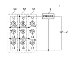
- the lamp lighting circuit 1 includes a power supply 2, a constant voltage circuit 3, and lamps L1 to L6.
- the power source 2 is, for example, a battery in an in-vehicle device, and supplies a power source voltage to a constant voltage circuit 3 to be described later.
- the constant voltage circuit 3 is also called a stabilized power supply, converts the voltage supplied from the power supply 2 into a preset voltage, and stabilizes and outputs the converted voltage so as not to fluctuate.
- the lamps L1 to L6 are light-emitting elements that include a filament and emit light when the voltage is applied to both ends of the filament.
- the lamps L1 to L6 all have the same characteristics (rated voltage, rated current, luminous flux, etc.).
- the lamps L1 and L2 are connected in series to form a series circuit S1
- the lamps L3 and L4 are connected in series to form a series circuit S2
- the lamps L5 and L6 are connected in series to form a series circuit S3.
- the series circuits S1 to S3 are connected in parallel, and a constant voltage determined in advance from the constant voltage circuit 3 is applied to both ends of the series circuits S1 to S3.
- the lamp lighting circuit 1 includes an intermediate point A between the lamps L1 and L2 connected in series, an intermediate point B between the lamps L3 and L4 connected in series, an intermediate point C between the lamps L5 and L6 connected in series, Are connected to each other. That is, the intermediate point A and the intermediate point B and the intermediate point B and the intermediate point C of the adjacent series circuit are connected.
- the intermediate points A, B, and C are voltage points that are theoretically set to the same potential when one end of the series connection is used as a reference potential.
- simply connecting in series as shown in FIG. 1 causes the potential to fluctuate due to variations in filament resistance of the lamps L1 to L6. That is, since the voltage applied to both ends of the series circuits S1 to S3 is divided by the filament resistance ratio, if the filament resistance varies, in this embodiment, 1 of the voltage supplied from the constant voltage circuit 3 is used.
- the potentials of the intermediate points A, B, and C that should be / 2 will fluctuate.
- the filament resistance distribution during the manufacture of the lamps L1 to L6 has a symmetrical bell shape and is close to a normal distribution. Therefore, the value obtained by dividing the resistance value of the population average of the normal distribution by the number of parallel circuits can be approximated to the combined resistance value when the dispersed filament resistors are connected in parallel.
- the intermediate point A, the intermediate point B, and the intermediate point C are connected so that all the lamps of the series circuit constituting the parallel circuit are connected in parallel. Therefore, the combined resistance value of the lamp groups (lamps L1, L3, and L5 and lamps L2, L4, and L6) configured at the same potential with respect to the reference potential, that is, the parallel combined resistance value between the lamp groups is almost equal. It will be the same.
- the voltage applied to each of the lamps L1 to L6 can be made substantially the same voltage.
- the circuit S2 in which the lamps L3 and L4 are connected in series are connected in parallel.
- a constant voltage can be set, and luminance unevenness and lifetime variations can be suppressed.
- two lamps are connected in series, but may be three as shown in FIG.
- intermediate points D, E, and F which are voltage points set to the same potential with respect to the reference potential
- the parallel combined resistance of the lamps L1, L4, and L7, the parallel combined resistance of the lamps L2, L5, and L8 and the parallel combined resistance of the lamps L3, L6, and L9 are substantially the same.
- the number of series may be four or more, or four or more series circuits may be connected in parallel. A larger number of parallels is more effective because the number of lamps for calculating the parallel combined resistance increases, and the resistance value is closer to the average value (population average) of the normal distribution of filament resistance.
- the above-described lamp lighting circuit 1 on an in-vehicle device (for example, a car stereo device) as an electronic device, it is possible to reduce luminance unevenness and lifetime variation of the in-vehicle device. Further, it is very effective when applied to a case where even a slight luminance unevenness is noticeable, such as a panel surface illuminated by a plurality of lamps.
- an in-vehicle device for example, a car stereo device
- the combined resistance values of the filaments of the lamp groups (lamps L1, L3, and L5) configured at the same potential can be made substantially the same, and the voltages applied to these lamp groups are also the same. It becomes almost the same. Accordingly, since a voltage with little variation is applied to each lamp, luminance unevenness is eliminated, and variation in lifetime can be suppressed. Further, since it can be realized only by adding wiring, it can be performed at low cost.
Landscapes
- Circuit Arrangement For Electric Light Sources In General (AREA)
Abstract
ランプが直列に接続された回路を、複数並列接続した場合において、低コストに輝度ムラを解消し、かつ、ランプの寿命のばらつきを抑えることができるランプ点灯回路及びそれを備えた電子機器を提供する。 ランプL1とL2を直列接続した回路S1、ランプL3とL4を直列接続した回路S2、ランプL5とL6を直列接続した回路S3、を並列に接続したランプ回路1において、基準電位に対して同電位とされる電圧点であるランプL1とL2の中間点Aと、ランプL3とL4の中間点Bと、ランプL5とL6の中間点Cと、を接続する。
Description
フィラメントを備えたランプを点灯させるランプ点灯回路およびそれを備えた電子機器に関する。
電子機器として例えば車載用機器の照明に用いられるランプは、車両の走行や停止などによるバッテリー電圧の変動によってランプ印加電圧が変化するためにランプの輝度が変化してしまう。そのため、バッテリー電圧の変動の影響を取り除く為、定電圧回路を用いてランプ印加電圧を安定化して点灯させている。
バッテリー電圧は通常12Vであり、定電圧回路によって安定化する電圧はこのバッテリー電圧が減電したことを想定すれば10V以下の設定値とすることが望ましい。
また、ランプの特性として同じ輝度を得るには、印加電圧が高ければ印加電流は少なく、印加電圧が低ければ印加電流は多くする必要がある。つまり、印加電圧が高ければランプのフィラメント径が細くなり、印加電圧が低ければランプのフィラメント径が太くなるので、耐震性を良くするためには印加電圧は低めで印加電流を多めの設定としたランプが有利となるために、一般的には8V程度の特性のランプが用いられることが多い。
その結果、定電圧回路の出力電圧は8V程度に設定される。ところが、近年、車載用機器の照明に用いられるランプは、輝度の確保、ばらつき防止、照明する面積の拡大等により、多数使用する方向にある。そのため、ランプを駆動する定電圧回路の損失が増大してしまうという問題があった。
このような問題に対しては、定電圧回路の損失を低減させるために出力電圧を上げれば損失の低減を抑えることができる。具体的には、使用されているランプを例えば電圧8V品から10V品に変更とすることで定電圧回路の損失を改善することはできる。この場合、ランプのフィラメント径が細くなり耐震性及び点灯寿命が低下してしまうという問題がある。
そのため、耐震性及び寿命を確保するために印加電圧の低いランプを使用し、さらに直列接続することによって印加電圧を上げるという方法が用いられてきた。定電圧回路の電圧設定値は、定電圧電源の損失を抑えるための条件(ちらつきが発生する減電電圧等)が許される限り出力電圧を上昇させた値に設定することで損失を低減させることができる。具体的には図1に示す回路100が用いられている。
図1に示した回路100は、バッテリー101と、定電圧回路102と、ランプL11~L16と、を備え、ランプL11とL12とが直列接続された回路S11と、ランプL13とL14とが直列接続された回路S12と、ランプL15とL16とが直列接続された回路S13と、が並列接続されており、各回路S11~S13にバッテリー101の電圧を定電圧回路102で一定電圧に安定化して供給している。
図1に示した回路の場合、各ランプに印加される電圧は、直列接続されたランプ同士のフィラメント抵抗の比で決定されるためにランプ製造時のばらつきによって輝度ムラが発生し易くなる。
ランプの輝度ムラを取り除く方法としては特許文献1に記載の複数個のランプ点灯方法が提案されている。特許文献1に記載の複数個のランプ点灯方法は、個々のランプを定格電流の最小値に設定した定電流回路により駆動させることでランプの輝度ムラを取り除いている。
特開平10-284259号公報
しかしながら、特許文献1に記載の複数個のランプ点灯方法は、各ランプに定電流回路を設けた並列接続回路は輝度ムラ、ランプ寿命には有効であるが、ランプ直列回路に定電流駆動した場合、ランプ寿命には有効だがランプに印加される電圧が異なるために輝度ムラには効果がない。さらに、図1に示したようなランプが直列に接続された回路を、複数並列接続した構成の場合に対しては何ら解決策が示されていない。
そこで、本発明は、ランプが直列に接続された回路を、複数並列接続した場合において、低コストに輝度ムラを解消し、かつ、ランプの寿命のばらつきを抑えることができるランプ点灯回路及びそれを備えた電子機器を提供することを課題とする。
上記課題を解決するために、請求項1に記載のランプ点灯回路は、フィラメントを備えた同一特性のランプを直列接続された回路が複数並列接続されたランプ点灯回路において、複数の前記ランプを直列接続した回路の基準電位に対して同電位とされる電圧点が互いに接続されていることを特徴としている。
1 ランプ点灯回路
3 定電圧回路
L1~L9 ランプ
S1~S3 直列回路(ランプを直列接続した回路)
A~F 中間点(基準電位に対して同電位とされる電圧点)
3 定電圧回路
L1~L9 ランプ
S1~S3 直列回路(ランプを直列接続した回路)
A~F 中間点(基準電位に対して同電位とされる電圧点)
以下、本発明の一実施形態にかかるランプ点灯回路を説明する。本発明の一実施形態にかかるランプ点灯回路は、ランプを直列接続した回路それぞれの基準電位に対して同電位とされる電圧点が互いに接続されているので、基準電位に対して同電位で構成されるランプ群のフィラメントの合成抵抗値をほぼ同一とすることができ、これらのランプ群に印加される電圧もほぼ同一となる。従って、個々のランプにはばらつきの少ない電圧が印加されるために輝度ムラが解消され、寿命のばらつきも抑えることができる。また、配線の追加のみで実現できるので低コストに行うことができる。
また、基準電位に対して同電位とされる電圧点は、直列接続されたランプとランプとの中間点としてもよい。このようにすることにより、直列接続されたランプの一端から数えて同じ位置のランプが並列に接続されることとなり、これら一端から数えて同じ位置のランプ群のフィラメントの合成抵抗値をほぼ同一とすることができるので、これらのランプ群に印加される電圧もほぼ同一となる。従って、個々のランプにはばらつきの少ない電圧が印加されるために輝度ムラが解消され、寿命のばらつきも抑えることができる。
また、上述したランプ点灯回路を電子機器に備えてもよい。このようにすることにより、例えば車載機器などの電子機器に用いられるランプの輝度ムラを低コストに解消し、かつ、ランプの寿命のばらつきも低コストに抑えることができる。
本発明の一実施例にかかるランプ点灯回路1を図2および図3を参照して説明する。ランプ点灯回路1は、図2に示すように電源2と、定電圧回路3と、ランプL1~L6と、を備えている。
電源2は、例えば車載機器であればバッテリーであり、後述する定電圧回路3に対して電源電圧を供給する。
定電圧回路3は、安定化電源とも呼ばれ、電源2から供給された電圧を予め設定された電圧に変換し、変換された電圧が変動しないように安定化させて出力する。
ランプL1~L6は、フィラメントを備え、フィラメントの両端に電圧を印加することによって該フィラメントが発光して光を発する発光素子である。なお、ランプL1~L6は全て同一の特性(定格電圧、定格電流、光束など)を持つものである。
ランプL1とL2は直列接続されて直列回路S1を構成し、ランプL3とL4は直列接続されて直列回路S2を構成し、ランプL5とL6は直列接続されて直列回路S3を構成している。
直列回路S1~S3は並列に接続され、直列回路S1~S3の両端には定電圧回路3から予め定めた一定電圧が印加される。
また、ランプ点灯回路1は、直列接続されたランプL1とL2の中間点Aと、直列接続されたランプL3とL4の中間点Bと、直列接続されたランプL5とL6の中間点Cと、が互いに接続されている。つまり、隣接する直列回路の中間点Aと中間点B、および、中間点Bと中間点Cが接続されている。
ランプL1~L6は全て同一の特性を持つので、中間点A、B、Cは、直列接続の一端を基準電位とした場合に、理論上同電位とされる電圧点である。しかしながら、図1のように単に直列接続しただけでは、ランプL1~L6のフィラメント抵抗のばらつきにより電位が変動してしまう。つまり、直列回路S1~S3の両端に印加される電圧はフィラメント抵抗比で分圧されるので、フィラメント抵抗にばらつきがあると、本実施例の場合、定電圧回路3から供給される電圧の1/2となるはずの中間点A、B、Cの電位が変動してしまう。
ところで、ランプL1~L6製造時のフィラメント抵抗の分布は左右対称の釣鐘形になり、正規分布に近くなることは周知である。そのため、この正規分布の母平均の抵抗値を並列回路数で割った値は、ばらついたフィラメント抵抗を並列接続した時の合成抵抗値に近似することができる。
そこで本実施例では、中間点Aと中間点Bと中間点Cとを接続して、並列回路を構成する直列回路の全てのランプが並列に接続されるようにしている。従って、基準電位に対して同電位で構成されるランプ群(ランプL1、L3、L5と、ランプL2、L4、L6)の合成された抵抗値、つまり、ランプ群同士の並列合成抵抗値はほぼ同一となる。
ランプ群同士の並列合成抵抗値がほぼ同一となるために、各ランプL1~L6に印加される電圧もほぼ同電圧とすることができる。
本実施例によれば、ランプL1とL2を直列接続した回路S1、ランプL3とL4を直列接続した回路S2、ランプL5とL6を直列接続した回路S3、を並列に接続したランプ回路1において、同電位とされる電圧点であるランプL1とL2の中間点Aと、同電位とされる電圧点であるランプL3とL4の中間点Bと、同電位とされる電圧点であるランプL5とL6の中間点Cと、を接続しているので、同電位で構成されるランプ群の並列合成抵抗値をほぼ同一とすることができるために、各ランプL1~L6に印加される電圧もほぼ一定電圧とすることができ、輝度ムラや寿命のばらつきを抑制することができる。
また、特別な回路素子を追加することなく、中間点Aと中間点Bと中間点Cを接続する配線を追加するのみで、低コストに輝度ムラや寿命のばらつきを抑制することができる。
また、上述した構成により、輝度ムラが抑えられるため、例えばランプを複数搭載した電子機器の製造時における輝度ムラをチェックする工程を省略することができる。
なお、上述した実施例では直列接続されたランプは2つであったが、図3に示すように3つであってもよい。図3の場合は、中間点A、B、Cの接続以外に、基準電位に対して同電位とされる電圧点である中間点D、E、Fを接続する。これによって、ランプL1、L4、L7の並列合成抵抗と、ランプL2、L5、L8の並列合成抵抗と、ランプL3、L6、L9の並列合成抵抗と、がほぼ同一となる。勿論、直列数は4つ以上でもよいし、4つ以上の直列回路が並列に接続されていてもよい。なお、並列数が多い方が、並列合成抵抗を算出するランプの数が増えるために、よりフィラメント抵抗の正規分布の平均値(母平均)に近い抵抗値となるためより効果が大きい。
また、図2や図3の構成では、全ての中間点を接続していたが、輝度ムラを抑制したい部分の中間点を接続する構成としてもよい。例えば、図3のように3つのランプが直列接続された回路の場合、中間点A、B、Cのみを接続する構成としてもよい。
また、上述したランプ点灯回路1を電子機器としての車載機器(例えばカーステレオ装置など)に搭載することで、車載機器の照明の輝度ムラや寿命のばらつきを少なくすることができる。また、複数のランプで照明されるパネル面など、わずかな輝度ムラでも目立つ場合に適用すると非常に効果的である。
前述した実施例によれば、以下のランプ点灯回路1が得られる。
(付記)フィラメントを備えた同一特性のランプL1、L2を直列接続した回路S1と、ランプL3、L4を直列接続した回路S2とランプL5、L6を直列接続した回路S3と、が並列接続されたランプ点灯回路1において、
複数の直列回路S1~S3の基準電位に対して同電位とされる電圧点A、B、Cが互いに接続されていることを特徴とするランプ点灯回路1。
複数の直列回路S1~S3の基準電位に対して同電位とされる電圧点A、B、Cが互いに接続されていることを特徴とするランプ点灯回路1。
このランプ点灯回路1によれば、同電位で構成されるランプ群(ランプL1、L3、L5)のフィラメントの合成抵抗値をほぼ同一とすることができ、これらのランプ群に印加される電圧もほぼ同一となる。従って、個々のランプにはばらつきの少ない電圧が印加されるために輝度ムラが解消され、寿命のばらつきも抑えることができる。また、配線の追加のみで実現できるので低コストに行うことができる。
なお、前述した実施例は本発明の代表的な形態を示したに過ぎず、本発明は、実施例に限定されるものではない。すなわち、本発明の骨子を逸脱しない範囲で種々変形して実施することができる。
Claims (3)
- フィラメントを備えた同一特性のランプを直列接続した回路が複数並列に接続されたランプ点灯回路において、
複数の前記ランプを直列接続した回路の基準電位に対して同電位とされる電圧点が互いに接続されていることを特徴とするランプ点灯回路。 - 前記基準電位に対して同電位とされる電圧点は、直列接続された前記ランプと前記ランプとの中間点であることを特徴とする請求項1に記載のランプ点灯回路。
- 請求項1または2に記載のランプ点灯回路を備えたことを特徴とする電子機器。
Priority Applications (1)
| Application Number | Priority Date | Filing Date | Title |
|---|---|---|---|
| PCT/JP2008/063116 WO2010010605A1 (ja) | 2008-07-22 | 2008-07-22 | ランプ点灯回路及びそれを備えた電子機器 |
Applications Claiming Priority (1)
| Application Number | Priority Date | Filing Date | Title |
|---|---|---|---|
| PCT/JP2008/063116 WO2010010605A1 (ja) | 2008-07-22 | 2008-07-22 | ランプ点灯回路及びそれを備えた電子機器 |
Publications (1)
| Publication Number | Publication Date |
|---|---|
| WO2010010605A1 true WO2010010605A1 (ja) | 2010-01-28 |
Family
ID=41570083
Family Applications (1)
| Application Number | Title | Priority Date | Filing Date |
|---|---|---|---|
| PCT/JP2008/063116 Ceased WO2010010605A1 (ja) | 2008-07-22 | 2008-07-22 | ランプ点灯回路及びそれを備えた電子機器 |
Country Status (1)
| Country | Link |
|---|---|
| WO (1) | WO2010010605A1 (ja) |
Citations (2)
| Publication number | Priority date | Publication date | Assignee | Title |
|---|---|---|---|---|
| JPS59157997A (ja) * | 1983-02-25 | 1984-09-07 | 螢光商事株式会社 | 照明装置の修理点検方法 |
| JPH09312199A (ja) * | 1996-05-22 | 1997-12-02 | Shiyoomei:Kk | 照明器具 |
-
2008
- 2008-07-22 WO PCT/JP2008/063116 patent/WO2010010605A1/ja not_active Ceased
Patent Citations (2)
| Publication number | Priority date | Publication date | Assignee | Title |
|---|---|---|---|---|
| JPS59157997A (ja) * | 1983-02-25 | 1984-09-07 | 螢光商事株式会社 | 照明装置の修理点検方法 |
| JPH09312199A (ja) * | 1996-05-22 | 1997-12-02 | Shiyoomei:Kk | 照明器具 |
Similar Documents
| Publication | Publication Date | Title |
|---|---|---|
| JP4776596B2 (ja) | 車両用灯具の点灯制御装置 | |
| US20040042205A1 (en) | Circuit for illuminator | |
| KR101087742B1 (ko) | 차량용 램프 장치 | |
| EP3512308A1 (en) | Lighting circuit, vehicle lamp, and driving method for light source | |
| JP5603160B2 (ja) | 半導体光源点灯回路および制御方法 | |
| CN100504523C (zh) | 液晶显示器的背光驱动装置和驱动该背光驱动装置的方法 | |
| WO2010010605A1 (ja) | ランプ点灯回路及びそれを備えた電子機器 | |
| US10327294B2 (en) | Voltage-dependent connection of individual light sources | |
| CN115336392A (zh) | 车辆用灯具系统及其控制器 | |
| KR100826413B1 (ko) | 멀티 램프 구동 장치 | |
| CN212163785U (zh) | 显示屏背光led驱动电路、显示装置及电子装置 | |
| US20140312794A1 (en) | Three-way omni-directional led lamp driver circuit | |
| US20020117898A1 (en) | Power-supply device for electrical components which are installed in a motor vehicle | |
| WO2012020616A1 (ja) | 発光素子基板群、発光装置、液晶表示装置 | |
| US11832361B2 (en) | Low electromagnetic interference lighting device with variable output levels | |
| KR101847801B1 (ko) | 차량 램프용 엘이디 구동 모듈의 기준전압 출력 회로 | |
| JP7103128B2 (ja) | 調光装置 | |
| US20110221359A1 (en) | Apparatus for Driving Field Emission Lamp | |
| JP2014037175A (ja) | 車両用灯具の制御回路 | |
| JP5103811B2 (ja) | バックライト調光制御装置 | |
| JP2025083022A (ja) | 電圧安定化装置及び電気機器システム | |
| JP2025080399A (ja) | 点灯モジュール | |
| CN108267916B (zh) | 激光光源及显示设备 | |
| JP2009266420A (ja) | バックライトユニット、及び、液晶表示装置 | |
| US6392359B1 (en) | System and method for reducing wavelength variations between light emitting diodes |
Legal Events
| Date | Code | Title | Description |
|---|---|---|---|
| 121 | Ep: the epo has been informed by wipo that ep was designated in this application |
Ref document number: 08791397 Country of ref document: EP Kind code of ref document: A1 |
|
| NENP | Non-entry into the national phase |
Ref country code: DE |
|
| 122 | Ep: pct application non-entry in european phase |
Ref document number: 08791397 Country of ref document: EP Kind code of ref document: A1 |
|
| NENP | Non-entry into the national phase |
Ref country code: JP |