WO2010002148A2 - 영상 부호화 및 복호화 장치 및, 방법 - Google Patents
영상 부호화 및 복호화 장치 및, 방법 Download PDFInfo
- Publication number
- WO2010002148A2 WO2010002148A2 PCT/KR2009/003457 KR2009003457W WO2010002148A2 WO 2010002148 A2 WO2010002148 A2 WO 2010002148A2 KR 2009003457 W KR2009003457 W KR 2009003457W WO 2010002148 A2 WO2010002148 A2 WO 2010002148A2
- Authority
- WO
- WIPO (PCT)
- Prior art keywords
- frequency coefficients
- frequency
- zero
- encoding
- coefficient
- Prior art date
- Legal status (The legal status is an assumption and is not a legal conclusion. Google has not performed a legal analysis and makes no representation as to the accuracy of the status listed.)
- Ceased
Links
Images






Classifications
-
- H—ELECTRICITY
- H04—ELECTRIC COMMUNICATION TECHNIQUE
- H04N—PICTORIAL COMMUNICATION, e.g. TELEVISION
- H04N19/00—Methods or arrangements for coding, decoding, compressing or decompressing digital video signals
- H04N19/60—Methods or arrangements for coding, decoding, compressing or decompressing digital video signals using transform coding
-
- H—ELECTRICITY
- H04—ELECTRIC COMMUNICATION TECHNIQUE
- H04N—PICTORIAL COMMUNICATION, e.g. TELEVISION
- H04N19/00—Methods or arrangements for coding, decoding, compressing or decompressing digital video signals
- H04N19/50—Methods or arrangements for coding, decoding, compressing or decompressing digital video signals using predictive coding
- H04N19/503—Methods or arrangements for coding, decoding, compressing or decompressing digital video signals using predictive coding involving temporal prediction
- H04N19/51—Motion estimation or motion compensation
- H04N19/577—Motion compensation with bidirectional frame interpolation, i.e. using B-pictures
-
- H—ELECTRICITY
- H04—ELECTRIC COMMUNICATION TECHNIQUE
- H04N—PICTORIAL COMMUNICATION, e.g. TELEVISION
- H04N19/00—Methods or arrangements for coding, decoding, compressing or decompressing digital video signals
- H04N19/10—Methods or arrangements for coding, decoding, compressing or decompressing digital video signals using adaptive coding
- H04N19/134—Methods or arrangements for coding, decoding, compressing or decompressing digital video signals using adaptive coding characterised by the element, parameter or criterion affecting or controlling the adaptive coding
- H04N19/136—Incoming video signal characteristics or properties
- H04N19/137—Motion inside a coding unit, e.g. average field, frame or block difference
-
- H—ELECTRICITY
- H04—ELECTRIC COMMUNICATION TECHNIQUE
- H04N—PICTORIAL COMMUNICATION, e.g. TELEVISION
- H04N19/00—Methods or arrangements for coding, decoding, compressing or decompressing digital video signals
- H04N19/90—Methods or arrangements for coding, decoding, compressing or decompressing digital video signals using coding techniques not provided for in groups H04N19/10-H04N19/85, e.g. fractals
- H04N19/93—Run-length coding
Definitions
- the present invention relates to an image encoding and decoding apparatus for encoding and / or decoding moving image data, and a method thereof, and to an apparatus and method for adaptively encoding moving image data reflecting characteristics of an image.
- the data constituting the moving image has a much larger amount of data than audio or still image data, it requires a lot of hardware resources including memory to store or transmit itself without any processing. Accordingly, in order to prevent this, the video data is compressed and stored or transmitted using an encoder, and the decoder receives and plays the video data.
- Moving Picture Experts Group (MPEG) and Video Coding Experts Group (VCEG) have developed video compression techniques that are superior to the existing MPEG-4 Part 2 and H.263 standards.
- the new standard is called H.264 / AVC (Advanced video Coding), which was jointly released as MPEG-4 Part 10 AVC and ITU-T Recommendation H.264.
- An object of the present invention is to provide an apparatus and method for improving the efficiency of image encoding and decoding by adaptively encoding by reflecting characteristics of an image in encoding and decoding video data.
- the present invention includes a prediction unit for predicting a predicted pixel value of each pixel of a current block of an image;
- a subtraction unit configured to generate a residual signal by calculating a difference value between an original pixel value of each pixel of the current block and a predicted pixel value of each pixel of the current block;
- a converter for converting the residual signal into frequency coefficients;
- a quantizer for quantizing the transformed frequency coefficients;
- the present invention includes a prediction step of predicting the predicted pixel value of each pixel of the current block of the image; A subtraction step of generating a residual signal by calculating a difference value between an original pixel value of each pixel of the current block and a predicted pixel value of each pixel of the current block; Converting the residual signal into frequency coefficients; A quantization step of quantizing the transformed frequency coefficients; And encoding quantized frequency coefficients, but encoding run_before (the number of frequency coefficients '0' between a current non-zero frequency coefficient and a previous non-zero frequency coefficient). It provides a video encoding method comprising the encoding step of encoding using one of the tables.
- the present invention includes a scanning step of scanning and quantizing the quantized frequency coefficients of each pixel of the current block of the image into a one-dimensional vector; Scanned quantized frequency coefficients include TotalCoeff (number of non-'0 'frequency coefficients), level (count value of non-'0' frequency coefficients), total_zero ('0' before last non-'0 'frequency coefficients) Number of frequency coefficients), and run_before (the number of frequency coefficients that are '0' between the current non-zero frequency coefficient and the previous non-zero frequency coefficient).
- the encoded information includes an output step of outputting a bit string.
- the present invention provides an input method comprising: an input step of reading an input bitstream; TotalCoeff (number of non-'0 'frequency coefficients), level (count value of non-'0' frequency coefficients), total_zero ('0' before last non-'0 'frequency information Number of frequency coefficients), and run_before (the number of frequency coefficients that are '0' between the current non-zero frequency coefficient and the previous non-zero frequency coefficient) to decode run_before.
- a decoding step of decoding using one of different variable length coding tables It provides a decoding method comprising the step of restoring the decoded frequency coefficients in the original block form.
- the present invention can improve the efficiency of image encoding and decoding by adaptively encoding by reflecting characteristics of an image in encoding and decoding video data.
- FIG. 1 is a diagram illustrating video frames constituting a video used for inter prediction.
- FIG. 2 is a block diagram of a video encoding apparatus according to an embodiment of the present invention.
- FIG. 3 is a flowchart illustrating a method of encoding quantized frequency coefficients in the encoder of FIG. 2.
- FIG. 4 is a diagram illustrating a frequency coefficient string zigzag scanned of the quantized frequency coefficients of FIG. 3.
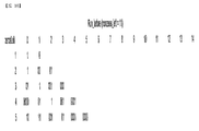
- 5A and 5B are variable length coding tables of run_before according to zero_left among variable length coding tables of H.264 / AVC (Advanced video coding).
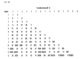
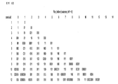
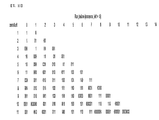
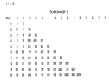
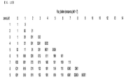
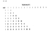
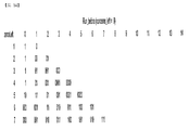
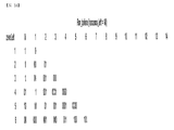
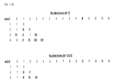
- 6 to 17 show different values of non_zero_left encoding run_before according to zero_left for 1, 2, 3, 4, 5, 6, 7, 8, 9, 10, 11, 12, 13, and 14, respectively. Length code tables are shown.
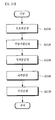
- FIG. 18 is a flowchart of another method of encoding quantized frequency coefficients in the encoder of FIG.
- 19 is a flowchart of an image encoding method according to another embodiment of the present invention.
- 20 is a block diagram schematically illustrating an electronic configuration of an image decoding apparatus according to another embodiment of the present invention.
- 21 is a flowchart illustrating a video decoding method according to another embodiment of the present invention.
- FIG. 22 is a flowchart of a decoding method of decoding a block of frequency coefficients from information of a bitstream encoded in the decoding step of FIG. 21.
- the video screen is composed of 30 frames in one second, the difference is small between one frame and neighboring frames, and thus cannot be distinguished by the human eye. For this reason, when 30 frames are sprayed in one second, the human eye recognizes the frames as continuous.
- the pixel value of the next frame can be predicted from the known pixel values constituting the previous frame (this is called interprediction).
- the encoding and decoding of such video data is performed based on a motion prediction technique.
- the motion prediction is performed by referring to past frames or referring to both past and future frames based on the time axis.
- the frame referred to to encode or decode the current frame is called a reference frame.
- block-based video encoding one still image (frame) constituting a video is divided into macroblocks and subblocks constituting the macroblock, and motion is predicted in units of blocks and encoding is performed.
- run_before refers to the number of frequency coefficients that are '0' between the current non-zero frequency coefficient and the previous non-zero frequency coefficient among the quantized frequency coefficients
- non_zero_left is the current '0'.
- 'No' refers to the number of non-zero '0' frequency coefficients remaining at the location of frequency
- TotalCoeff refers to the number of frequency coefficients other than '0'
- level refers to the coefficient value of non-zero frequency coefficients.
- total_zero refers to the number of frequency coefficients that are '0' before the last frequency coefficient that is not '0'.
- trailingOnes refers to the number of frequency coefficients having an absolute value of 1 continuously when the last consecutive absolute value is 1 among zigzag scanned quantized frequency coefficients
- trailing_ones_sign_flag refers to the sign of trailingOnes.
- FIG. 1 is a diagram illustrating video frames constituting a video used for inter prediction.
- video data is composed of a series of still images. These still images are divided into GOP (Group of Picture) units. Each still image is called a frame.
- GOP Group of Picture
- One GOP includes an I frame 110, a P frame 120, and a B 130 frame.
- the I frame 110 is a frame that is encoded by itself without using a reference frame
- the P frame 120 and the B frame 130 are frames that are encoded by performing motion estimation and compensation using the reference frame.
- the B frame 130 is a frame that is encoded by predicting the frame of the past and the frame of the future in the forward and reverse directions (bidirectional), respectively.
- FIG. 2 is a block diagram of a video encoding apparatus according to an embodiment of the present invention.
- the video encoding apparatus 200 includes a predictor 210, a subtractor 220, a transformer 230, a quantizer 240, and an encoder 250.
- the video encoding apparatus 300 may be a personal computer (PC), a notebook computer, a personal digital assistant (PDA), a portable multimedia player (PMP), or a PlayStation Portable (PSP). ),
- a communication device such as a communication modem for communicating with various devices or a wired / wireless communication network, a memory for storing various programs and data for encoding an image, and executing a program.
- the prediction unit 210 currently uses any one or a combination of intra prediction based on motion prediction or intra prediction that predicts the next pixel using a correlation of pixel signals within the same frame.
- a block (or macroblock) can be predicted.
- the prediction unit 210 may be divided into a motion estimation unit (not shown) and a motion compensation unit (not shown).
- the motion estimator finds the motion prediction value of the macroblock of the current frame in the reference frame and outputs the difference of the motion as a motion vector. That is, the macroblock to be searched is searched within a predetermined search area of the reference frame to find the most similar macroblock and the degree of movement is output as a motion vector.
- the motion compensation unit obtains a prediction macro block corresponding to the obtained motion vector from the reference frame.
- the predictor 210 is an intra predictor that predicts a current macroblock of a current frame using a neighboring macroblock of a current macroblock in an image, and at least one pixel value of at least one neighboring macroblock.
- the predicted macroblock is predicted by calculating a predicted pixel value of each pixel of the current macroblock using.
- the peripheral macroblock may be one or more peripheral macroblocks that are compressed before the current macroblock and located around the current macroblock.
- the subtraction unit 220 generates a residual signal by subtracting the prediction macro block from the macro block of the original image frame and calculating the difference value.
- the transformer 230 converts the residual signal generated by the subtractor 220 into a frequency domain to obtain frequency coefficients.
- the transform unit 230 may convert the residual signal into the frequency domain by using various transformation techniques such as a discrete cosine transform (DCT), which transforms an image signal on a time axis into a frequency axis. Convert. In the case of the I frame described with reference to FIG. 1, the converter 230 converts the macroblock of the original image frame into the frequency domain.
- DCT discrete cosine transform
- the quantization unit 240 quantizes the frequency coefficients transformed into the frequency domain by the conversion unit 230.
- Subtracting the predictive macroblock from the macroblock of the original picture frame is called a residual signal, and the residual signal value is encoded to reduce the amount of data during encoding. Since an error occurs during the quantization process, the video data generated in the bitstream includes an error generated during the transformation and quantization process.
- the video encoding apparatus 200 may further include an inverse quantizer 360 and an inverse transform unit 370 to obtain a reference frame.
- the quantized residual signal is combined with an image predicted by the predictor 210 through an inverse quantizer 360 and an inverse transformer 270 and stored in a reference frame storage (not shown).
- a reference frame storage not shown
- I frame it is stored in the reference frame storage of the predictor 210 through the inverse quantizer 360 and the transformer 370.
- the reference image stored in the reference image storage unit becomes an image including an encoding error generated during a transform and quantization process in the original image frame.
- the converter 230 receives A-B, which is a difference between the original image and the predicted image, and performs conversion.
- A-B which is a difference between the original image and the predicted image
- the reference image storage unit stores (A-B) + E and the predicted image B and stores the image A + E, which includes an error in the original image, as a reference image.
- the encoder 250 encodes the frequency coefficients quantized by the quantizer 240 into a bitstream.
- An entropy encoding technique may be used as the encoding technique, but various encoding techniques may be used without being limited thereto.
- the encoder 250 encodes using coded block pattern information without entropy encoding. Otherwise, the encoding unit 250 encodes values of frequency coefficients other than '0' in order, and then encodes the values '0'. Encode the location of the frequency coefficients rather than
- Table 1 1 (1) 0 (2) 0 (6) 0 (7) 0 (3) 0 (5) 0 (8) 0 (13) 3 (4) 0 (9) 0 (12) 0 (14) 0 (10) 0 (11) 0 (15) 0 (16)
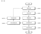
- FIG. 3 is a flowchart illustrating a method of encoding quantized frequency coefficients in the encoder 250 of FIG. 2.
- FIG. 4 is a diagram illustrating a frequency coefficient string zigzag scanned of the quantized frequency coefficients of FIG. 3.
- a zigzag scan of quantized frequency coefficients is performed (S310).
- Table 1 () shows the zigzag scan order. Therefore, the zigzag scanned frequency coefficient sequence is 1 (1) 0 (2) 0 (3) 3 (4) 0 (5) 0 (6) 0 (7) 0 (8) as shown in FIG. 0 (9) 0 (10) 0 (11) 0 (12) 0 (13) 0 (14) 0 (15) 0 (16).
- total_coeff is encoded using a variable length coding table of H.264 / Advanced video coding (AVC).
- AVC Advanced video coding
- one of the variable length encoding tables may be adaptively selected according to the situation of surrounding macroblocks to perform encoding.
- frequency coefficient values other than '0' are encoded in the reverse or reverse order (high frequency to DC direction) as +3 and +1 (S330).
- the level may be encoded using a variable length coding table of H.264 / AVC (Advanced video Coding).
- run_before according to the number of frequency coefficients (zero_left) having the previous value of '0' remaining at the position of the frequency coefficient other than the current '0' may be encoded using one of different variable length coding tables.
- the run_before for zero_left may be encoded using different variable length coding tables according to the number of non-zero frequency coefficients remaining (non_zero_left) remaining at positions other than the current '0'.
- 5A and 5B illustrate a variable length coding table of run_before according to zero_left in a variable length coding table of H.264 / AVC.
- variable-length encoding table of run_before according to zero_left of FIGS. 5A and 5B when encoding run_before for representing the position of the next frequency coefficient other than '0', the encoding length is changed based on information theory according to zero_left. have.
- variable-length encoding table for example, if zero_left is '2', run_before encodes 0, 1, and 2 in order of 1, 2, and 2 bits, respectively. If zero_left is '3', run_before encodes 0, 1, 2, and 3 with a length of 2 bits, respectively.
- this variable length coding table is generally encoded with a few bits as the run_before is smaller, but it is not possible to construct a variable length coding table using a general probability characteristic of an image in which many non-zero frequency coefficients appear in the low frequency part. .
- non_zero_left the number of non-zero frequency coefficients present in the DC direction of the current non-zero frequency coefficients (non_zero_left) based on a general probability characteristic of an image in which many non-zero frequency coefficients appear in the low frequency portion. For example, a plurality of variable length encoding tables for encoding run_before according to zero_left are used.
- the table value of FIG. 5A represents the number of bits used for encoding the corresponding run_before for the corresponding zero_left
- the table value of FIG. 5B represents an encoded value used for encoding the corresponding run_before for the corresponding zero_left.
- the run_before value 2 is encoded into two bits.
- run_before The value 2 is encoded as '00'.
- variable length encoding table of FIGS. 6 to 17 is only one example, and may be variously changed or modified based on a general probability characteristic of an image in which a frequency coefficient other than '0' appears in a low frequency portion.
- different variable-length coding tables encoding run_before according to zero_left are used based on a general probability characteristic of an image in which many non-zero frequency coefficients appear in the low frequency portion, thereby efficiently quantizing blocks of quantized frequency coefficients. Can be encoded.
- run_before 0, 1, and 2 are encoded in order of 1, 1, and 2, whereas in FIG. 6, when non_zero_left is 1, zero_left is 2.
- run_before 0, 1, 2 are encoded in order of 2, 2, 1 bits.
- the number of bits of run_before may be smaller as the probability that the frequency coefficient other than the previous '0' is located before the frequency coefficient other than the current '0' is higher.
- variable length coding table may be smaller in size as the value of the number of non-zero frequency coefficients remaining other than '0' remains. That is, in the variable length coding tables of FIGS. 6 to 17, the value of non_zero_left is 1, 2, 3, 4, 5, 6, 7, 8, 9, 10, 11, 12, 13, 14, and the value of non_zero_left. It can be seen that as the size increases, the size of the variable length coding table decreases. For example, if non-zero_left is 14, zero_left is 1. Also, if non_zero_left is 15, it does not need to remain.
- the coded bitstreams of the quantized frequency coefficients of Table 1 through steps S310 to S350 are 2 (total_coeff), +3 (level), +1 (level), and 2 (total_zeros) as shown in Table 2. ), And 2 (run_before) information.
- FIG. 18 is a flowchart of another method of encoding quantized frequency coefficients in the encoder of FIG. In this case, steps overlapping with FIG. 3 are the same as those described with reference to FIG.
- a zigzag scan of quantized frequency coefficients is performed (S1810).
- the frequency coefficient zigzag scan of the quantized frequency coefficients in Table 3 is 15 (1) -4 (2) 7 (3) 0 (4) 0 (5) 9 (6) -2 (7) 0 (8) 0 (9) 1 (10) 0 (11) -1 (12) 0 (13) 0 (14) 0 (15) 0 (16).
- trailingones and trailing_ones_sign_flag can be encoded using a variable length encoding table of H.264 / AVC.
- the frequency coefficient level other than '0' except the coefficient whose absolute value is 1 is encoded in the reverse order (high frequency to DC direction) as -2, +9, +7, -4, +15 ( S12050).
- run_before between -1 (12) and +1 (10) is 1, run_before between +1 (10) and -2 (7) is 2, and between -2 (7) and +9 (6)
- Run_before of run_before between +9 (6) and +7 (3) is 2, +7 (3) and -4 (2) and each run_before between -4 (2) and +15 is 0, so run_before
- the reverse order is 1, 2, 0, 2, 0, 0.
- Each of these run_befores (1, 2, 0, 2, 0, 0) selects one of the variable length coding tables of FIGS. 6 to 17 in consideration of non_zero_lefts, and encodes according to zero_left in the selected variable length incubation tables. The value is determined.
- Bitstreams in which the quantized frequency coefficients of Table 3 are encoded through steps S1810 to S1870 are shown in Table 4. That is, the bitstream is 7 (total_coeff), 2 (trailingones),-(trailing_ones_sign_flag), + (trailing_ones_sign_flag), -2 (level), +9 (level), +7 (level), -4 (level), + It consists of 15 (level), 5 (total_zeros), 1 (run_before), 2 (run_before), 0 (run_before), 2 (run_before), 0 (run_before), and 0 (run_before).
- the image encoded in the bitstream by the image encoding apparatus 200 is real-time or non-real-time through the wired or wireless communication network such as the Internet, local area wireless communication network, wireless LAN network, WiBro network, mobile communication network, or the like.
- the image decoding apparatus may be transmitted to a video decoding apparatus through a communication interface such as a universal serial bus (USB), decoded by the video decoding apparatus, and restored and reproduced.
- a communication interface such as a universal serial bus (USB)
- 19 is a flowchart of an image encoding method according to another embodiment of the present invention.
- an image encoding method includes a prediction step S1910, a subtraction step S1920, a transform step S1930, a quantization step S1940, and an encoding step S1950. .
- the prediction step S1910 is a step of predicting pixel values of each pixel of the current block of the image.
- the prediction step S1910 generates a prediction block by predicting pixel values of each pixel of the current block by a previously encoded block of a previous frame or a neighboring block of the current frame.
- a difference (ie, a residual signal) between the original pixel value of the current block to be encoded and the prediction pixel value of the prediction block is calculated to reduce the amount of encoded data to increase coding efficiency.
- the converting step S1930 is a step of converting the generated residual signal into the frequency domain by using a DCT transform.
- the quantization step S1940 is a step of quantizing the frequency coefficients transformed into the frequency domain.
- the encoding step (S1950) is a step of encoding the quantized frequency coefficients into the types of information in Table 2 or Table 4 using a variable length encoding table. Specific steps of the encoding step S1950 are omitted in the encoding method described with reference to FIGS. 3 to 18.
- CAVLC context-based adaptive variable length coding
- an image encoding method may further include an inverse quantization step S1960 and an inverse transform step S1970.
- the inverse quantization step S1960 and the inverse transform step S1970 are steps of generating a residual signal through inverse quantization and inverse transformation of quantized frequency coefficients. That is, the quantized residual signal is combined with the image predicted in the prediction step S1910 through the inverse quantization step S1960 and the inverse transform step S1970 and stored as a reference frame.
- the image encoded in the bitstream by the image encoding apparatus 200 is real-time or non-real-time through the wired or wireless communication network such as the Internet, local area wireless communication network, wireless LAN network, WiBro network, mobile communication network, or the like.
- the image decoding apparatus may be transmitted to a video decoding apparatus through a communication interface such as a universal serial bus (USB), decoded by the video decoding apparatus, and restored and reproduced.
- a communication interface such as a universal serial bus (USB)
- 20 is a block diagram schematically illustrating an electronic configuration of an image decoding apparatus according to another embodiment of the present invention.
- the image decoding apparatus 2000 is an apparatus for predicting a current block of an image using one or more neighboring blocks around the current block and decoding the image.
- An inverse quantizer 2020 is an apparatus for predicting a current block of an image using one or more neighboring blocks around the current block and decoding the image.
- An inverse quantizer 2020 is an apparatus for predicting a current block of an image using one or more neighboring blocks around the current block and decoding the image.
- An inverse quantizer 2020 is an inverse quantizer 2020, an inverse transformer 2030, an adder 2040, and a predictor 2050.
- the video decoding apparatus 800 may be a personal computer (PC), a notebook computer, a personal digital assistant (PDA), a portable multimedia player (PMP: Portable Multimedia Player (PSP), PlayStation Portable (PSP: PlayStation Portable), Mobile Communication Terminal (Mobile Communication Terminal) and the like, communication devices, such as a communication modem for performing communication with various devices or wired and wireless communication network, decoding the image Means a variety of devices including a memory for storing various programs and data, a microprocessor for executing and controlling the program by executing.
- PC personal computer
- PDA personal digital assistant
- PMP Portable Multimedia Player
- PSP PlayStation Portable
- Mobile Communication Terminal Mobile Communication Terminal
- the decoder 2010 decodes the bitstream and extracts quantized frequency coefficients. That is, the decoder 2010 decodes a bitstream, which is an image encoded by the image encoding apparatus 300, and extracts quantized frequency coefficients including pixel information of the current block of the image.
- the decoder 2010 decodes the quantized frequency coefficients using the variable length coding tables described above from the information included in Table 2 or Table 4 included in the bitstream.
- the decoder 2010 may include encoded information 2 (total_coeff), +3 (level), +1 (level), 2 (total_zeros), and 2 ( run_before), using the variable length coding tables shown in FIGS. 6 to 17, using the frequency coefficient sequence shown in FIG. 4 (1 (1) 0 (2) 0 (3) 3 (4) 0 (5)).
- a specific decoding method will be described next with reference to FIGS. 21 and 22.
- the dequantizer 2020 de-quantizes the frequency coefficients extracted from the bitstream by the decoder 2010.
- the inverse transform unit 2030 generates inverse trasformation of the frequency coefficients inversely quantized by the inverse quantizer 2020 into a time domain.
- the adder 2030 restores the original pixel value of the current block by adding the residual signal inversely transformed by the inverse transformer 2020 and the predicted pixel value of each pixel of the current block predicted by the predictor 2050.
- 21 is a flowchart illustrating a video decoding method according to another embodiment of the present invention.
- the image decoding apparatus 800 which receives and stores a bitstream of an image through a wired or wireless communication network or a cable, may reproduce the current block of the image in order to reproduce the image according to a user's selection or an algorithm of another program being executed.
- the prediction is performed using one or more neighboring blocks around the block or the current block, and the image is decoded and reconstructed.
- the image decoding method to restore the information contained in the bitstream to a quantized frequency coefficient representing the information on the pixel value of the current block of the image using a variable length coding table Decoding step (S2110), inverse quantization step of inverse quantizing the extracted quantized frequency coefficient (S2120), inverse transform step (S2130) to inverse transform the inverse quantized frequency coefficients to the time domain to restore the residual signal, inverse transform to the time domain Predicting the current block by using the current block indicated by the residual signal that has been processed, using the corresponding block of the previous frame or one or more neighboring blocks around the current block (S2140), and the residual signal of the current block inversely transformed in step S2130; An addition step of restoring the original pixel value of the current block by adding the prediction pixel values of each pixel of the current block predicted in step S2140 (S2) 150).
- FIG. 22 is a flowchart of a decoding method of decoding a block of frequency coefficients from information of a bitstream encoded in the decoding step of FIG. 21.
- information (2) of a bitstream coded by the encoding method described above with reference to FIGS. total_coeff), +3 (level), +1 (level), 2 (total_zeros), and 2 (run_before)) are read (S2110).
- step S2230 After reading the first information (2 (total_coeff)) (S2220), the next information (+3 (level), +1 (level)) by the total_coeff value is read (S2230).
- the frequency coefficients read in step S2230 are +3 and +1.
- the frequency coefficient sequence obtained in step S2240 becomes 0 0 0 0 0 0 0 0 0 0 0 0 0 +3 +1.
- step S2250 the next information 2 (run_before) is read, and a coefficient of '0' is added as much as the run_before value between the frequency coefficients obtained in step S2240 (S2250).
- the frequency coefficient sequence obtained in step S2250 becomes 0 0 0 0 0 0 0 0 0 0 0 0 +3 0 0 +1.
- the run_before value may be decoded using the variable length encoding table of FIG. 6, and then S2260 may be performed.
- step S2250 the frequency coefficient sequence obtained in step S2250 is output in the reverse order and then restored to the original block form as shown in Table 2 (S2260).
- the quantized frequency coefficient sequence shown in Table 4 can also be decoded in the same manner.
- the original frequency coefficient sequence and the original macroblock can be restored by using the information and the run_before, total_coeff, and total_zeros values.
- the decoding process is performed by using the variable length coding table in the decoding step, and then the quantized frequency coefficients are restored to finally obtain an image. Can be restored to a block.
- the above-described video encoding method and decoding method can be created by a computer program. Codes and code segments constituting a program can be easily inferred by a computer programmer in the art.
- the program is stored in a computer readable media, and read and executed by a computer to implement a video encoding and decoding method.
- the information storage medium includes a magnetic recording medium, an optical recording medium, and a carrier wave medium.
Landscapes
- Engineering & Computer Science (AREA)
- Multimedia (AREA)
- Signal Processing (AREA)
- Compression Or Coding Systems Of Tv Signals (AREA)
- Compression, Expansion, Code Conversion, And Decoders (AREA)
Abstract
Description
| 1 (1) | 0 (2) | 0 (6) | 0 (7) |
| 0 (3) | 0 (5) | 0 (8) | 0 (13) |
| 3 (4) | 0 (9) | 0 (12) | 0 (14) |
| 0 (10) | 0 (11) | 0 (15) | 0 (16) |
| 정보의 종류 | 정보의 내용 | 정보 |
| total_coeff | '0'이 아닌 계수의 개수 | 2 |
| level | 양자화된 계수값 | +3 |
| level | 양자화된 계수값 | +1 |
| total_zeros | 마지막 계수 이전에 있는 '0'의 총 개수 | 2 |
| run_before | 계수 이전에 있는 연속된 '0'의 개수 | 2 |
| 15 (1) | -4 (2) | 9 (6) | -2(7) |
| 7 (3) | 0 (5) | 0 (8) | 0 (13) |
| 0 (4) | 0 (9) | -1 (12) | 0 (14) |
| 1 (10) | 0 (11) | 0 (15) | 0 (16) |
| 정보의 종류 | 정보 |
| total_coeff | 7 |
| trailingones | 2 |
| trailing_ones_sign_flag | - |
| trailing_ones_sign_flag | + |
| level | -2 |
| level | +9 |
| level | +7 |
| level | -4 |
| level | +15 |
| total_zeros | 5 |
| run_before | 1 |
| run_before | 2 |
| run_before | 0 |
| run_before | 2 |
| run_before | 0 |
| run_before | 0 |
Claims (25)
- 영상의 현재 블록의 각 화소의 예측 화소값을 예측하는 예측부;상기 현재 블록의 각 화소의 원 화소값과 상기 현재 블록의 각 화소의 예측 화소값의 차이값을 계산하여 잔차신호를 생성하는 감산부;상기 잔차신호를 주파수 계수들로 변환하는 변환부;상기 변환된 주파수 계수들을 양자화하는 양자화부; 및상기 양자화된 주파수 계수들을 부호화하되, run_before(현재의 '0'이 아닌 주파수 계수와 이전 '0'이 아닌 주파수 계수 사이에서 '0'인 주파수 계수의 개수)를 부호화할 때, 서로 다른 가변길이 부호화표들 중 하나를 사용하여 부호화하는 것을 특징으로 하는 부호화부를 포함하는 영상 부호화 장치.
- 제1항에 있어서,상기 가변길이 부호화표는 non_zero_left(현재의 '0'이 아닌 주파수의 위치에서 남아있는 이전 '0’이 아닌 주파수 계수의 개수)에 따라 다른 것을 특징으로 하는 영상 부호화 장치.
- 제2항에 있어서,상기 부호화부는, 상기 양자화된 주파수 계수들을, TotalCoeff('0'이 아닌 주파수 계수의 개수), level('0'이 아닌 주파수 계수들의 계수값), total_zero('0'이 아닌 마지막 주파수 계수 이전의 '0'인 주파수 계수의 개수)의 부호화를 추가로 포함하여 문맥기반 적응적 가변길이 부호화로 부호화하는 것을 특징으로 하는 영상 부호화 장치.
- 제2항에 있어서,상기 가변길이 부호화표에서, 상기 run_before의 비트수는 이전 '0'이 아닌 주파수 계수가 현재의 '0'이 아닌 주파수 계수 이전에 위치할 확률이 높을수록 작은 것을 특징으로 하는 영상 부호화 장치.
- 제2항에 있어서,상기 가변길이 부호화표는 남아있는 상기 non_zero_left의 값이 커질수록 크기가 작아지는 것을 특징으로 하는 영상 부호화 장치.
- 제3항에 있어서,상기 부호화부는, 지그재그 스캔한 상기 양자화된 주파수 계수들을, 상기 TotalCoeff, 상기 level, 상기 total_zero, 상기 run_before 순서로 부호화하는 것을 특징으로 하는 영상 부호화 장치.
- 제6항에 있어서,상기 부호화부는, 지그재그 스캔한 상기 양자화된 주파수 계수들 중 마지막에 연속하는 절대값이 1인 계수가 존재하는 경우, trailingOnes(마지막에 연속적으로 나오는 절대값이 1인 주파수 계수의 개수)와 trailing_ones_sign_flag(상기 trailingOnes의 부호)를 추가로 포함하여 부호화하고,상기 trailingOnes와 상기 trailing_ones_sign_flag는 상기 TotalCoeff, 상기 level 사이에 위치하는 것을 특징으로 하는 영상 부호화 장치.
- 영상의 현재 블록의 각 화소의 예측 화소값을 예측하는 예측단계;상기 현재 블록의 각 화소의 원 화소값과 상기 현재 블록의 각 화소의 예측 화소값의 차이값을 계산하여 잔차신호를 생성하는 감산단계;상기 잔차신호를 주파수 계수들로 변환하는 변환단계;상기 변환된 주파수 계수들을 양자화하는 양자화단계; 및상기 양자화된 주파수 계수들을 부호화하되, run_before(현재의 '0'이 아닌 주파수 계수와 이전 '0'이 아닌 주파수 계수 사이에서 '0'인 주파수 계수의 개수)를 부호화할 때, 서로 다른 가변길이 부호화표들 중 하나를 사용하여 부호화하는 부호화단계를 포함하는 것을 특징으로 하는 영상 부호화 방법.
- 제8항에 있어서,상기 가변길이 부호화표는 non_zero_left(현재의 '0'이 아닌 주파수의 위치에서 남아있는 이전 '0’이 아닌 주파수 계수의 개수)에 따라 다른 것을 특징으로 하는 영상 부호화 방법.
- 제9항에 있어서,상기 부호화단계는, 상기 양자화된 주파수 계수들을, TotalCoeff('0'이 아닌 주파수 계수의 개수), level('0'이 아닌 주파수 계수들의 계수값), total_zero('0'이 아닌 마지막 주파수 계수 이전의 '0'인 주파수 계수의 개수)의 부호화를 추가로 포함하여 문맥기반 적응적 가변길이 부호화로 부호화하는 것을 특징으로 하는 영상 부호화 방법.
- 제9항에 있어서,상기 가변길이 부호화표에서, 상기 run_before의 비트수는 이전 '0'이 아닌 주파수 계수가 현재의 '0'이 아닌 주파수 계수 이전에 위치할 확률이 높을수록 작은 것을 특징으로 하는 영상 부호화 방법.
- 제9항에 있어서,상기 가변길이 부호화표는 남아있는 상기 non_zero_left의 값이 커질수록 크기가 작아지는 것을 특징으로 하는 영상 부호화 방법.
- 제10항에 있어서,상기 부호화단계는, 지그재그 스캔한 상기 양자화된 주파수 계수들을, 상기 TotalCoeff, 상기 level, 상기 total_zero, 상기 run_before 순서로 부호화하는 것을 특징으로 하는 영상 부호화 방법.
- 제13항에 있어서,상기 부호화단계는, 지그재그 스캔한 상기 양자화된 주파수 계수들 중 마지막에 연속하는 절대값이 1인 계수가 존재하는 경우, trailingOnes(마지막에 연속적으로 나오는 절대값이 1인 주파수 계수의 개수)와 trailing_ones_sign_flag(상기 trailingOnes의 부호)를 추가로 포함하여 부호화하고,상기 trailingOnes와 상기 trailing_ones_sign_flag는 상기 TotalCoeff, 상기 level 사이에 위치하는 것을 특징으로 하는 영상 부호화 방법.
- 영상의 현재 블록의 각 화소의 양자화된 주파수 계수들을 스캔하여 일차원 벡터로 배열하는 스캔단계와;스캔한 상기 양자화된 주파수 계수들을, TotalCoeff('0'이 아닌 주파수 계수의 개수), level('0'이 아닌 주파수 계수들의 계수값), total_zero('0'이 아닌 마지막 주파수 계수 이전의 '0'인 주파수 계수의 개수), run_before(현재의 '0'이 아닌 주파수 계수와 이전 '0'이 아닌 주파수 계수 사이에서 '0'인 주파수 계수의 개수) 순서로 부호화할 때, 서로 다른 가변길이 부호화표들 중 하나를 사용하여 부호화하는 부호화단계와;상기 부호화된 정보들은 비트열로 출력하는 출력단계를 포함하는 것을 특징으로 하는 부호화 방법.
- 제15항에 있어서,상기 가변길이 부호화표는 non_zero_left(현재의 '0'이 아닌 주파수의 위치에서 남아있는 이전 '0’이 아닌 주파수 계수의 개수)에 따라 다른 것을 특징으로 하는 부호화 방법.
- 제15항에 있어서,상기 가변길이 부호화표에서, 상기 run_before의 비트수는 이전 '0'이 아닌 주파수 계수가 현재의 '0'이 아닌 주파수 계수 이전에 위치할 확률이 높을수록 작은 것을 특징으로 하는 부호화 방법.
- 제15항에 있어서,상기 가변길이 부호화표는 남아있는 상기 non_zero_left의 값이 커질수록 크기가 작아지는 것을 특징으로 하는 부호화 방법.
- 제15항에 있어서,지그재그 스캔한 상기 양자화된 주파수 계수들 중 마지막에 연속하는 절대값이 1인 주파수 계수가 존재하는 경우, trailingOnes(마지막에 연속적으로 나오는 절대값이 1인 주파수 계수의 개수)와 trailing_ones_sign_flag(상기 trailingOnes의 부호)를 추가로 포함하여 부호화하고,상기 trailingOnes와 상기 trailing_ones_sign_flag는 상기 TotalCoeff, 상기 level 사이에 위치하는 것을 특징으로 하는 부호화 방법.
- 제15항에 있어서,상기 출력단계에서, 상기 level과 상기 run_before가 복수인 경우 역순으로 출력하는 것을 특징으로 하는 부호화 방법.
- 입력된 비트스트림을 읽는 입력단계와;읽어들인 상기 비트스트림의 정보들 중 TotalCoeff('0'이 아닌 주파수 계수의 개수), level('0'이 아닌 주파수 계수들의 계수값), total_zero('0'이 아닌 마지막 주파수 계수 이전의 '0'인 주파수 계수의 개수), run_before(현재의 '0'이 아닌 주파수 계수와 이전 '0'이 아닌 주파수 계수 사이에서 '0'인 주파수 계수의 개수)를 이용하여 주파수 계수를 복호화하되, 상기 run_before를 복호화할 때 서로 다른 가변길이 부호화표들 중 하나를 사용하여 복호화하는 복호화단계와;복호화된 주파수 계수들을 원래의 블록 형태로 복원하는 복원단계를 포함하는 것을 특징으로 하는 복호화 방법.
- 제21항에 있어서,상기 가변길이 부호화표는 non_zero_left(현재의 '0'이 아닌 주파수의 위치에서 남아있는 이전 '0’이 아닌 주파수 계수의 개수)에 따라 다른 것을 특징으로 하는 복호화 방법.
- 제22항에 있어서,상기 가변길이 부호화표에서, 상기 run_before의 비트수는 이전 '0'이 아닌 주파수 계수가 현재의 '0'이 아닌 주파수 계수 이전에 위치할 확률이 높을수록 작은 것을 특징으로 하는 복호화 방법.
- 제22항에 있어서,상기 가변길이 부호화표는 남아있는 상기 non_zero_left의 값이 커질수록 크기가 작아지는 것을 특징으로 하는 복호화 방법.
- 제22항에 있어서,상기 입력단계에서, 상기 입력된 비트스트림 정보는, 마지막에 연속하는 절대값이 1인 주파수 계수가 존재하는 경우, trailingOnes(마지막에 연속적으로 나오는 절대값이 1인 주파수 계수의 개수)와 trailing_ones_sign_flag(상기 trailingOnes의 부호)를 상기 TotalCoeff, 상기 level 사이에 추가로 포함하며,상기 복호화단계는, 상기 trailingOnes와 상기 trailing_ones_sign_flag를 추가로 이용하여 상기 주파수 계수를 복호화하는 것을 특징으로 하는 복호화 방법.
Priority Applications (1)
| Application Number | Priority Date | Filing Date | Title |
|---|---|---|---|
| US13/002,582 US9319710B2 (en) | 2008-07-04 | 2009-06-26 | Video encoding and decoding apparatus and method |
Applications Claiming Priority (2)
| Application Number | Priority Date | Filing Date | Title |
|---|---|---|---|
| KR10-2008-0064903 | 2008-07-04 | ||
| KR1020080064903A KR101501568B1 (ko) | 2008-07-04 | 2008-07-04 | 영상 부호화 및 복호화 장치 및, 방법 |
Publications (2)
| Publication Number | Publication Date |
|---|---|
| WO2010002148A2 true WO2010002148A2 (ko) | 2010-01-07 |
| WO2010002148A3 WO2010002148A3 (ko) | 2010-04-22 |
Family
ID=41466431
Family Applications (1)
| Application Number | Title | Priority Date | Filing Date |
|---|---|---|---|
| PCT/KR2009/003457 Ceased WO2010002148A2 (ko) | 2008-07-04 | 2009-06-26 | 영상 부호화 및 복호화 장치 및, 방법 |
Country Status (3)
| Country | Link |
|---|---|
| US (1) | US9319710B2 (ko) |
| KR (1) | KR101501568B1 (ko) |
| WO (1) | WO2010002148A2 (ko) |
Families Citing this family (5)
| Publication number | Priority date | Publication date | Assignee | Title |
|---|---|---|---|---|
| KR20130049526A (ko) * | 2011-11-04 | 2013-05-14 | 오수미 | 복원 블록 생성 방법 |
| KR20130049523A (ko) | 2011-11-04 | 2013-05-14 | 오수미 | 인트라 예측 블록 생성 장치 |
| KR20130050404A (ko) * | 2011-11-07 | 2013-05-16 | 오수미 | 인터 모드에서의 복원 블록 생성 방법 |
| WO2020138352A1 (ja) * | 2018-12-26 | 2020-07-02 | パナソニック インテレクチュアル プロパティ コーポレーション オブ アメリカ | 三次元データ符号化方法、三次元データ復号方法、三次元データ符号化装置、及び三次元データ復号装置 |
| WO2020141855A1 (ko) * | 2019-01-01 | 2020-07-09 | 엘지전자 주식회사 | 영상 코딩 시스템에서 레지듀얼 부호 관련 정보를 사용하는 영상 디코딩 방법 및 그 장치 |
Family Cites Families (31)
| Publication number | Priority date | Publication date | Assignee | Title |
|---|---|---|---|---|
| US6104754A (en) * | 1995-03-15 | 2000-08-15 | Kabushiki Kaisha Toshiba | Moving picture coding and/or decoding systems, and variable-length coding and/or decoding system |
| CA2467266A1 (en) * | 2001-11-22 | 2003-05-30 | Matsushita Electric Industrial Co., Ltd. | Variable length coding method and variable length decoding method |
| US7599835B2 (en) * | 2002-03-08 | 2009-10-06 | Nippon Telegraph And Telephone Corporation | Digital signal encoding method, decoding method, encoding device, decoding device, digital signal encoding program, and decoding program |
| US7099387B2 (en) * | 2002-03-22 | 2006-08-29 | Realnetorks, Inc. | Context-adaptive VLC video transform coefficients encoding/decoding methods and apparatuses |
| US6795584B2 (en) * | 2002-10-03 | 2004-09-21 | Nokia Corporation | Context-based adaptive variable length coding for adaptive block transforms |
| US6646578B1 (en) * | 2002-11-22 | 2003-11-11 | Ub Video Inc. | Context adaptive variable length decoding system and method |
| US20040120404A1 (en) * | 2002-11-27 | 2004-06-24 | Takayuki Sugahara | Variable length data encoding method, variable length data encoding apparatus, variable length encoded data decoding method, and variable length encoded data decoding apparatus |
| KR100959532B1 (ko) * | 2003-12-18 | 2010-05-27 | 엘지전자 주식회사 | Cavlc 복호 방법 |
| KR100674941B1 (ko) * | 2005-01-13 | 2007-01-26 | 삼성전자주식회사 | 내용 적응 가변 길이 부호화 장치 및 방법 |
| US20050259742A1 (en) * | 2004-05-21 | 2005-11-24 | Hellman Timothy M | System and method for choosing tables in CAVLC |
| US7830964B2 (en) * | 2004-11-24 | 2010-11-09 | Lsi Corporation | Method and/or apparatus for parsing compressed video bitstreams |
| JP4502384B2 (ja) * | 2004-11-25 | 2010-07-14 | キヤノン株式会社 | 可変長符号復号化装置及び可変長符号復号化方法 |
| US20060126744A1 (en) * | 2004-12-10 | 2006-06-15 | Liang Peng | Two pass architecture for H.264 CABAC decoding process |
| JP4271134B2 (ja) * | 2004-12-10 | 2009-06-03 | 株式会社東芝 | 可変長符号化デコーダおよびデコード方法 |
| JP2006203682A (ja) * | 2005-01-21 | 2006-08-03 | Nec Corp | 動画像圧縮符号化ビットストリームシンタックス変換装置及び動画像通信システム |
| US7751636B2 (en) * | 2005-09-23 | 2010-07-06 | Faraday Technology Corp. | Method for decoding transform coefficients corresponding to an image |
| JP4879558B2 (ja) * | 2005-11-02 | 2012-02-22 | パナソニック株式会社 | 動きベクトル検出装置 |
| US7245242B2 (en) * | 2005-11-28 | 2007-07-17 | Conexant Systems, Inc. | Decoding systems and methods |
| JP4844449B2 (ja) * | 2006-04-17 | 2011-12-28 | 日本ビクター株式会社 | 動画像符号化装置、方法、プログラム、動画像復号化装置、方法、およびプログラム |
| KR100813877B1 (ko) * | 2006-05-11 | 2008-03-18 | 전자부품연구원 | 효율적인 h.264/avc cavlc 디코딩 방법 |
| TWI314820B (en) * | 2006-05-26 | 2009-09-11 | Ind Tech Res Inst | Pattern-search based method for context-adaptive variable length coding/decoding |
| KR100801967B1 (ko) * | 2006-07-07 | 2008-02-12 | 광주과학기술원 | 문맥 기반 적응적 가변 길이 부호화 인코더 및 디코더,문맥 기반 적응성 가변 길이 부호화하는 방법과 복호화하는방법 및 이를 이용한 동영상 전송 시스템. |
| JP4379444B2 (ja) * | 2006-07-26 | 2009-12-09 | ソニー株式会社 | 復号化方法、復号化方法のプログラム、復号化方法のプログラムを記録した記録媒体、復号化装置 |
| US8325819B2 (en) * | 2006-10-12 | 2012-12-04 | Qualcomm Incorporated | Variable length coding table selection based on video block type for refinement coefficient coding |
| JP4356028B2 (ja) * | 2007-05-17 | 2009-11-04 | ソニー株式会社 | 情報処理装置および方法 |
| US8938009B2 (en) * | 2007-10-12 | 2015-01-20 | Qualcomm Incorporated | Layered encoded bitstream structure |
| BRPI0818444A2 (pt) * | 2007-10-12 | 2016-10-11 | Qualcomm Inc | codificação adaptativa de informação de cabeçalho de bloco de vídeo |
| US8848787B2 (en) * | 2007-10-15 | 2014-09-30 | Qualcomm Incorporated | Enhancement layer coding for scalable video coding |
| JPWO2009075107A1 (ja) * | 2007-12-13 | 2011-04-28 | パナソニック株式会社 | 画像符号化装置、符号化レート変換装置、映像音声ストリーム記録装置、ネットワーク配信システム、係数変換装置、集積回路及び画像符号化方法 |
| JP2010278668A (ja) * | 2009-05-27 | 2010-12-09 | Sony Corp | 符号化装置及び符号化方法、並びに復号装置及び復号方法 |
| US8410959B2 (en) * | 2010-04-09 | 2013-04-02 | Qualcomm, Incorporated | Variable length codes for coding of video data |
-
2008
- 2008-07-04 KR KR1020080064903A patent/KR101501568B1/ko not_active Expired - Fee Related
-
2009
- 2009-06-26 WO PCT/KR2009/003457 patent/WO2010002148A2/ko not_active Ceased
- 2009-06-26 US US13/002,582 patent/US9319710B2/en active Active
Also Published As
| Publication number | Publication date |
|---|---|
| US20110176605A1 (en) | 2011-07-21 |
| KR20100004625A (ko) | 2010-01-13 |
| WO2010002148A3 (ko) | 2010-04-22 |
| KR101501568B1 (ko) | 2015-03-12 |
| US9319710B2 (en) | 2016-04-19 |
Similar Documents
| Publication | Publication Date | Title |
|---|---|---|
| WO2010027182A2 (ko) | 서브블록 내 임의 화소를 이용한 영상 부호화/복호화 방법 및 장치 | |
| WO2013070006A1 (ko) | 스킵모드를 이용한 동영상 부호화 및 복호화 방법 및 장치 | |
| WO2013002549A2 (ko) | 영상 부호화/복호화 방법 및 장치 | |
| WO2013109039A1 (ko) | 가중치예측을 이용한 영상 부호화/복호화 방법 및 장치 | |
| WO2012011672A2 (ko) | 확장된 스킵모드를 이용한 영상 부호화/복호화 방법 및 장치 | |
| WO2010050706A2 (ko) | 움직임 벡터 부호화 방법 및 장치와 그를 이용한 영상 부호화/복호화 방법 및 장치 | |
| WO2013002550A2 (ko) | 고속 코딩 단위(Coding Unit) 모드 결정을 통한 부호화/복호화 방법 및 장치 | |
| WO2012033344A2 (ko) | 효과적인 화면내 예측모드 집합 선택을 이용한 영상 부호화/복호화 방법 및 장치 | |
| WO2013062193A1 (ko) | 영상 복호화 방법 및 장치 | |
| WO2012077960A2 (ko) | 임의의 형태의 블록을 이용한 인터예측에 의한 영상의 부호화/복호화 방법 및 장치 | |
| WO2010120113A2 (ko) | 예측 모드 선택 방법 및 장치와 그를 이용한 영상 부호화/복호화 방법 및 장치 | |
| WO2011037337A2 (ko) | 저주파수 성분을 고려한 영상 부호화/복호화 방법 및 장치 | |
| WO2013062196A1 (ko) | 영상 복호화 장치 | |
| WO2011068331A2 (ko) | 비디오 인코딩 장치 및 그 인코딩 방법, 비디오 디코딩 장치 및 그 디코딩 방법, 및 거기에 이용되는 방향적 인트라 예측방법 | |
| WO2011145836A2 (ko) | 인트라 블록 및 인터 블록이 혼합된 코딩블록을 이용하는 영상 부호화/복호화 장치 및 그 방법 | |
| WO2011145819A2 (ko) | 영상 부호화/복호화 장치 및 방법 | |
| WO2009157665A2 (ko) | 블록 변환을 이용한 인트라 예측 방법 및 장치와 그를 이용한 영상 부호화/복호화 방법 및 장치 | |
| WO2009113791A2 (ko) | 영상 부호화장치 및 영상 복호화장치 | |
| WO2012015275A2 (ko) | 블록 분할예측을 이용한 영상 부호화/복호화 방법 및 장치 | |
| WO2012093854A2 (ko) | 코딩 유닛 단위 병렬 인트라예측을 이용한 부호화/복호화 방법 및 장치 | |
| WO2010077071A2 (ko) | 블록 모드 부호화/복호화 방법 및 장치와 그를 이용한 영상 부호화/복호화 방법 및 장치 | |
| WO2012077959A2 (ko) | 노이즈성분을 위한 공간영역에서의 영상 부호화/복호화 방법 및 장치 | |
| WO2011108879A2 (ko) | 영상 부호화 장치, 그 영상 부호화 방법, 영상 복호화 장치 및 그 영상 복호화 방법 | |
| WO2011111954A2 (ko) | 움직임 벡터 해상도 조합을 이용한 움직임 벡터 부호화/복호화 방법 및 장치와 그를 이용한 영상 부호화/복호화 방법 및 장치 | |
| WO2013062194A1 (ko) | 복원 블록을 생성하는 방법 및 장치 |
Legal Events
| Date | Code | Title | Description |
|---|---|---|---|
| 121 | Ep: the epo has been informed by wipo that ep was designated in this application |
Ref document number: 09773684 Country of ref document: EP Kind code of ref document: A2 |
|
| NENP | Non-entry into the national phase |
Ref country code: DE |
|
| WWE | Wipo information: entry into national phase |
Ref document number: 13002582 Country of ref document: US |
|
| 32PN | Ep: public notification in the ep bulletin as address of the adressee cannot be established |
Free format text: NOTING OF LOSS OF RIGHTS PURSUANT TO RULE 112(1) EPC (EPO FORM 1205A DATED 11/04/11) |
|
| 122 | Ep: pct application non-entry in european phase |
Ref document number: 09773684 Country of ref document: EP Kind code of ref document: A2 |