WO2010001568A1 - Handle switch for vehicle - Google Patents
Handle switch for vehicle Download PDFInfo
- Publication number
- WO2010001568A1 WO2010001568A1 PCT/JP2009/002965 JP2009002965W WO2010001568A1 WO 2010001568 A1 WO2010001568 A1 WO 2010001568A1 JP 2009002965 W JP2009002965 W JP 2009002965W WO 2010001568 A1 WO2010001568 A1 WO 2010001568A1
- Authority
- WO
- WIPO (PCT)
- Prior art keywords
- switch
- steering wheel
- horn switch
- horn
- handle grip
- Prior art date
Links
Images


Classifications
-
- B—PERFORMING OPERATIONS; TRANSPORTING
- B62—LAND VEHICLES FOR TRAVELLING OTHERWISE THAN ON RAILS
- B62K—CYCLES; CYCLE FRAMES; CYCLE STEERING DEVICES; RIDER-OPERATED TERMINAL CONTROLS SPECIALLY ADAPTED FOR CYCLES; CYCLE AXLE SUSPENSIONS; CYCLE SIDE-CARS, FORECARS, OR THE LIKE
- B62K11/00—Motorcycles, engine-assisted cycles or motor scooters with one or two wheels
- B62K11/14—Handlebar constructions, or arrangements of controls thereon, specially adapted thereto
-
- B—PERFORMING OPERATIONS; TRANSPORTING
- B62—LAND VEHICLES FOR TRAVELLING OTHERWISE THAN ON RAILS
- B62K—CYCLES; CYCLE FRAMES; CYCLE STEERING DEVICES; RIDER-OPERATED TERMINAL CONTROLS SPECIALLY ADAPTED FOR CYCLES; CYCLE AXLE SUSPENSIONS; CYCLE SIDE-CARS, FORECARS, OR THE LIKE
- B62K23/00—Rider-operated controls specially adapted for cycles, i.e. means for initiating control operations, e.g. levers, grips
- B62K23/02—Rider-operated controls specially adapted for cycles, i.e. means for initiating control operations, e.g. levers, grips hand actuated
-
- H—ELECTRICITY
- H01—ELECTRIC ELEMENTS
- H01H—ELECTRIC SWITCHES; RELAYS; SELECTORS; EMERGENCY PROTECTIVE DEVICES
- H01H9/00—Details of switching devices, not covered by groups H01H1/00 - H01H7/00
- H01H9/02—Bases, casings, or covers
- H01H9/06—Casing of switch constituted by a handle serving a purpose other than the actuation of the switch, e.g. by the handle of a vacuum cleaner
- H01H2009/068—Casing of switch constituted by a handle serving a purpose other than the actuation of the switch, e.g. by the handle of a vacuum cleaner with switches mounted on a handlebar, e.g. for motorcycles, fork lift trucks, etc.
Definitions
- the present invention relates to a steering wheel switch of a vehicle, and more particularly, to providing a steering wheel switch of a vehicle that is easy to operate a horn switch and easy to distinguish from other switches.
- a switch box having operation switches such as horns, headlights, and blinkers so that various electrical components can be operated while holding the grip portion of the handlebar.
- switches such as horns, headlights, and blinkers so that various electrical components can be operated while holding the grip portion of the handlebar.
- a configuration is known which is mounted adjacent to the grip portion of the handlebar.
- the blinker switch it is common for the blinker switch to be at the center and the horn switch to be at the bottom.
- a blinker switch is disposed in the vicinity of the lower end of the switch box, and the horn switch on the outer side in the vehicle width direction and the dimmer on the inner side in the vehicle width direction
- switches optical axis changeover switches
- An object of the present invention is to solve the problems of the prior art and to provide a handlebar switch which is easy to operate a horn switch and easy to distinguish from other switches.
- the present invention relates to a steering wheel switch of a vehicle in which a switch housing including a horn switch and at least one other switch is disposed adjacent to a steering wheel grip attached to a steering wheel end. Is projected from the front view direction on the driver's side of the switch housing, and is disposed at a position overlapping the axis of the handle grip and on the vehicle rear side with respect to the other switch, and the other switch.
- a first feature is that the horn switch is vertically offset from the horn switch.
- a lever for a brake or a clutch which is operated while gripping the handle grip and pivots in the longitudinal direction of the vehicle about a pivot shaft, is provided adjacent to the switch housing, and the horn switch is When the switch housing is projected from the axial direction of the handle grip, the switch housing is disposed at a position overlapping with a line connecting the axial center of the handle grip and the central position of the pivot shaft.
- the horn switch is configured to swing by pressing in the direction of the axis of the handle grip about a swing axis provided at the end close to the handle grip.
- the horn switch is disposed so as to protrude outward from the switch housing, and the amount of protrusion from the switch housing is from an end near the handle grip provided with the swing shaft.
- a fourth feature lies in the fact that it increases toward the center of the vehicle body along the axis of the handle grip.
- a fifth feature is that the amount of protrusion of the horn switch is substantially zero at the end near the handle grip provided with the swing shaft.
- the sixth feature is that the operation surface of the horn switch becomes larger toward the center of the vehicle body along the axis of the handle grip from the end near the handle grip where the swing shaft is provided. is there.
- the horn switch has two contour lines vertically opposed to each other across the axis line of the handle grip, and a swing shaft of the horn switch is provided at a distance between the two contour lines.
- a seventh feature resides in that the diameter gradually increases from one side toward the other side along the axial direction of the handle grip.
- An eighth feature of the present invention is that the other switch is formed so that one side of the outline adjacent to the horn switch is formed along one of the two outlines of the horn switch. .
- a ninth feature is that the inboard portion of the horn switch is disposed closer to the center of the vehicle than the other switches.
- a tenth feature of the present invention is that the horn switch is shaped so that the axial direction of the handle grip is the longitudinal direction.
- an eleventh feature is that the other switch includes at least a turn signal switch or a light axis switching switch of a headlight.
- the first feature is that the horn switch is disposed at a position overlapping the axis of the steering wheel grip when projected from the front view direction on the driver side of the switch housing and further to the vehicle rear side than other switches. It is. Therefore, the horn switch is disposed at a position where the thumb is naturally extended along the axial direction of the handle grip from the state where the occupant grips the handle grip, and the operability of the horn switch is enhanced. In addition, it becomes easy to put a finger on the horn switch while holding the handle grip.
- the other switch is disposed vertically offset with respect to the horn switch. Thus, no other switch is present in the axial direction of the handle grip, which reduces the possibility of touching the other when the horn switch is operated.
- the second feature is that a lever for a brake or a clutch that operates while gripping the handle grip and pivots in the vehicle longitudinal direction about the pivot shaft is provided adjacent to the switch housing, and the horn switch is When the switch housing is projected from the axial direction of the handle grip, the switch housing is disposed at a position overlapping with a line connecting the axial center of the handle grip and the central position of the pivot shaft. Therefore, it is possible to arrange the horn switch in a range in which the thumb is naturally extended along the axial direction of the handle grip from the state where the occupant grips the handle grip.
- the third feature is that the horn switch is configured to swing by pressing in the direction of the axis of the handle grip about the swing axis provided at the end close to the handle grip. . Therefore, it is possible to obtain a swing type horn switch operated by pressing a portion near the center of the vehicle body. As a result, the possibility of pushing by the vibration even when traveling with the thumb on the horn switch is reduced, and by extending the thumb a little inward of the vehicle body, only the horn switch can be operated as intended by the occupant. it can. Therefore, the transition from the state in which the finger is put on the horn switch to the operation of the other switches can be smoothly performed.
- a fourth feature is that the horn switch is disposed so as to protrude outward from the switch housing, and the amount of protrusion from the switch housing is from the end near the handle grip provided with the swing shaft, It is a point that increases toward the center of the vehicle body along the axis of the handle grip. Therefore, it becomes easy to grasp which position of the horn switch the thumb is touching. Further, the protrusion amount of the horn switch becomes larger toward the center of the vehicle body. That is, since it becomes smaller toward the handle grip side, when moving the thumb up and down while holding the handle grip, the fingertip is less likely to be caught by the horn switch, and a smooth operation becomes possible.
- a fifth feature is that the amount of protrusion of the horn switch is substantially zero at the end close to the handle grip provided with the swing shaft. Therefore, it is further difficult for the fingertip to be caught on the horn switch, and the other switches can be operated more smoothly.
- a sixth feature is that the operation surface of the horn switch becomes larger toward the center of the vehicle along the axis of the steering wheel grip from the end near the steering wheel grip where the swinging shaft is provided. Therefore, the area of the operation surface of the horn switch becomes smaller toward the handle grip, and when the thumb is moved up and down while holding the handle grip to operate the other switches, the fingertip is less likely to be caught by the horn switch. In addition, since the operation surface on the handle grip side is small, the swing shaft can be shortened. Therefore, the frictional resistance of the rocking shaft can be reduced to improve the operability.
- a seventh feature is that the horn switch has two contour lines facing each other up and down across the axis of the handle grip, and the interval between the two contour lines is provided with the pivot axis of the horn switch It is a point that gradually increases from one side to the other side along the axial direction of the handle grip. Therefore, the area of the end on the operation unit side becomes larger than the area of the end on the swinging shaft side, and the pressing operation of the horn switch becomes easy.
- the shape of the horn switch can be easily grasped by the movement of the thumb in the left and right direction. In addition, it is possible to obtain a horn switch of a novel design which has not been made before.
- An eighth feature is that the other switch is formed such that one side of its contour line adjacent to the horn switch is along one of the two contour lines of the horn switch. Therefore, the gap formed between the horn switch and the other switch is formed to have a predetermined constant width, thereby further reducing the possibility of touching the other switch when the horn switch is operated. It is possible.
- a ninth feature is that the inboard portion of the horn switch is disposed closer to the center of the vehicle than the other switches. Therefore, it becomes easy to arrange all the switches along the path of the fingertip formed when moving the thumb up and down while holding the handle grip. Thereby, the operability of each switch can be further enhanced.
- a tenth feature is that the horn switch is shaped so that the axial direction of the handle grip is the longitudinal direction. Therefore, when the horn switch is moved in the axial direction while putting a finger on the horn switch, its shape can be easily grasped and operated, and the horn switch can be obtained.
- the other switch includes at least a turn signal switch or a light axis switching switch of a headlight. Therefore, the frequently used switch is disposed close to the horn switch, and a handle switch with high operability can be obtained.
- FIG. 1 is a partially enlarged view of a motorcycle to which a handlebar switch according to an embodiment of the present invention is applied. It is a front view of a handle switch. It is the top view seen from the A direction of FIG. It is the side view seen from the B direction of FIG.
- FIG. 5 is a cross-sectional view taken along the line EE of FIG. 3;
- FIG. 3 is a cross-sectional view taken along the line CC of FIG. 2; It is explanatory drawing which shows the relationship between a steering wheel switch and a passenger
- FIG. 7 is a partially enlarged view of a motorcycle to which a steering wheel switch according to a second embodiment of the present invention is applied. It is a top view of the handlebar switch which shows arrangement
- FIG. 10 is a side view of the handlebar switch including a cross-sectional view taken along line FF of FIG. 9;
- FIG. 1 is a partially enlarged view of a motorcycle 1 to which a steering wheel switch according to an embodiment of the present invention is applied.
- This figure is a view looking around the steering wheel from the rear and upper side of the vehicle body, and shows substantially the same state as seen by the occupant seated on the seat.
- a vehicle front side of a steering handle 15 for steering a front wheel (not shown) is covered with a cowling 2 as an exterior part.
- a transparent or translucent windproof screen 3 is attached to a central upper portion of the cowling 2, and a meter unit 4 including a speedometer, a tachometer, and the like is disposed below the windshield screen 3.
- the front wheels of the motorcycle 1 are rotatably supported at the lower ends of the pair of left and right front forks 8.
- An upper portion of the front fork 8 is fixed by a top bridge 6 having a key cylinder 7.
- the top bridge 6 is rotatably supported by a vehicle body frame (not shown) of the motorcycle 1.
- a pair of left and right handlebars 9 constituting a steering handle 15 is fixed to an upper end portion of the front fork 8. Thereby, the steering wheel 15 can steer the front wheel.
- a fuel tank 5 is disposed between the top bridge 6 and a seat (not shown).
- a handle grip 10 which is made of cylindrical rubber or the like and is gripped by an occupant, is attached.
- the right side of the lever located on the front side of the steering wheel grip 10 is the front wheel brake lever 11, and the left side thereof is the clutch lever 12.
- the handle grip 10 on the right side is rotatably supported with respect to the handle bar 9 and is configured to perform output adjustment of the power source by this rotation operation.
- a handlebar switch unit having switches of various electrical components is attached to the left and right handlebars 9 adjacent to the vehicle body center side of the handlebar grip 10.
- the right handle switch 50 is provided with a kill switch 51, a hazard lamp switch 52, and a starter switch 53.
- the left handle switch 30 is provided with a dimmer switch (optical axis changeover switch) 31 for the headlight, a horn switch 32 and a blinker switch 33.
- the handle switch according to the present invention is applied to the left handle switch 30 having the horn switch 32.
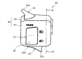
- FIG. 2 is a front view of the handlebar switch 30. As shown in FIG. The handlebar switch 30 is attached to the handlebar 9 so that the surface shown in the front view faces the occupant side (driver's side). 3 is a top view seen from the A direction of FIG. 2, and FIG. 4 is a side view seen from the B direction of FIG. Furthermore, FIG. 5 is a cross-sectional view taken along the line EE of FIG. The same reference numerals as above indicate the same or equivalent parts.
- the housing 60 made of resin or the like is composed of a front side (vehicle rear side) half 61 and a rear side (vehicle front side) half 62 which are divided into two in the longitudinal direction of the vehicle with the handlebar 9 interposed therebetween.
- the front half 61 is provided with a seesaw type dimmer switch 31, a rocking and pressing type horn switch 32, and a turn signal switch 33 which is tilted in the lateral direction of the drawing. These three switches can be operated only by moving the thumb while holding the handle grip 10.
- the rear half 62 of the housing 60 is provided with a passing light switch 34 which can be operated by the index finger while holding the handle grip 10.
- the passing light switch 34 is configured to perform a swing operation by pulling a protrusion 34a extending outward in the vehicle width direction toward the front side so as to hook it with a fingertip.
- a drain hole 35 having a labyrinth structure is provided inside.
- the three switches attached to the front half 61 are configured such that the other two switches are disposed vertically on the horn switch 32 substantially in the vertical direction in the front view of the handlebar switch 30. More specifically, the horn switch 32 is disposed at a position overlapping with the axis D of the handle grip 10 when projected in a front view, and is disposed on the vehicle rear side with respect to the other two switches. It is set up. According to this configuration, the horn switch 32 is disposed at a position where the thumb is naturally extended along the direction of the axis D from the state in which the handle grip 10 is gripped, and the operability of the horn switch 32 is enhanced. . Also, since no other switch is present in the direction of the axis D, identification of the horn switch 32 and other switches is facilitated.
- FIG. 9 is a top view of the handlebar switch 30 showing an arrangement relationship with peripheral parts.
- 10 is a side view of the handlebar switch 30 including a cross-sectional view taken along the line FF of FIG.
- the same reference numerals as above indicate the same or equivalent parts.
- a holder 80 for pivotally supporting the clutch lever 12 is attached.
- a master cylinder (not shown) of a hydraulic clutch interlocked with the clutch lever 12 is installed.
- a reservoir tank 83 of clutch fluid is provided at one end of the holder 80.
- a pivot shaft 85 of the clutch lever 12 is attached to a holder 80 which is clamped to the handle bar 9 by fixing the holder half 81 with a bolt 82.
- the pivot shaft 85 is disposed on the vehicle body front side of the steering wheel switch 30, and the axial direction thereof is directed in the vertical direction of the vehicle body.
- the clutch lever 12 is pivotally supported so as to be able to swing in the longitudinal direction of the vehicle body.
- horn switch 32 has axis D of handle grip 10 and center position G of pivot shaft 85 when viewed from projection of handle switch 30 in the axial direction of handle grip 10. Are arranged so as to overlap with the line H connecting the two. According to such an arrangement, the horn switch 32 is disposed in a range in which the thumb is naturally extended along the axial direction of the handle grip 10 from the state in which the driver grips the handle grip 10, to obtain high operability. Can. Further, according to the above-described arrangement, the horn switch 32 is positioned at a position overlapping the rocking surface formed when the clutch lever 12 is rocked.
- the horn switch 32 is disposed at a position where the line H and the substantially central position in the vertical direction of the horn switch 32 substantially coincide with each other, that is, the substantially central position of the housing 60 The position can be moved up and down within a range where at least a part of the horn switch 32 overlaps with the line H, as shown by broken lines O and P.
- a brake lever may be attached to the holder 80 instead of the clutch lever 12.
- the horn switch 32 is configured to swing about a swing shaft 36 provided at an end closer to the vehicle body.
- the swinging shaft 36 is disposed in a direction substantially perpendicular to the axis D in the front view of FIG. Therefore, the horn switch 32 performs a swing operation by pushing the operation surface 32e near the vehicle body inward toward the center of the axis D, that is, the front side of the vehicle.
- the horn switch 32 since the horn switch 32 is actuated by pressing a portion near the center of the vehicle body, the vehicle travels with the thumb on the position near the handle grip 10 of the horn switch 32, that is, the position near the pivot shaft 36. Even then, the possibility of unintentionally pushing this is reduced. Further, when the horn switch 32 is operated, the horn switch 32 can be pressed smoothly as intended by the occupant by extending the thumb slightly inward of the vehicle body.
- the horn switch 32 is shaped to have a longitudinal direction along the direction of the axis D.
- the inward portion (portion at the center of the vehicle body) 32c of the vehicle body is configured to project from the surface of the front half 61 toward the occupant.
- the amount of projection gradually increases from the vehicle body outer portion 32 d where the rocking shaft 36 is provided to the vehicle body inward portion 32 c along the longitudinal direction of the horn switch 32, that is, the direction of the axis D Is set as.
- the horn switch 32 is formed such that the area of the operation surface 32e becomes larger as it goes from the vehicle body outer part 32d to the vehicle body inward part 32c.
- the contour line of the vehicle body upper portion 32a of the horn switch 32 and the contour line of the vehicle body lower portion 32b are formed so as to form a pair on the upper and lower sides of the axis D. Then, the distance between the upper and lower contours gradually increases from the vehicle outer portion 32d toward the vehicle inner portion 32c, and the horn switch 32 is formed into a substantially fan-like shape which is diverged from the rocking shaft 36 toward the vehicle center It will be done.
- the area of the pressing portion is sufficiently secured, and the pressing operation of the horn switch 32 is facilitated.
- the shape of the switch can be easily grasped by the movement of the thumb in the left and right direction.
- the fingertip is less likely to be caught by the horn switch 32 when moving the thumb up and down.
- the lower side contour 31a adjacent to the horn switch 32 among the contours of the dimmer switch 31 is formed along the inclination angle of the contour of the vehicle body upper portion 32a of the horn switch 32.
- the upper contour 33a adjacent to the horn switch 32 is formed at an inclination angle along the contour of the vehicle body lower portion 32b of the horn switch 32.
- a plate member 43 formed of metal or the like is disposed between the front half 61 and the rear half 62 of the housing 60.
- the plate member 43 is formed with a protrusion 44 engaged with a positioning hole (not shown) provided in the handle bar 9.
- the handle 44 is positioned so that the projection 44 of the plate member 43 engages with the positioning hole of the handle bar 9.
- the bar 9 is pinched and coupled by a tapping screw or the like inserted into the screw hole 46.
- the diameter of the through hole 45 is substantially the same as the diameter of the handle bar 9.
- FIG. 6 is a cross-sectional view taken along the line CC of FIG. In this figure, only the front half 61 is shown.
- the horn switch 32 swings by pressing the operation surface 32 e closer to the vehicle body inward portion 32 c, that is, the vehicle body center side.
- the movable contact 38 pushes the inner pressing member 40 on the back surface side of the horn switch 32 and moves to the fixed contact 39 side.
- the movable contact 38 connected to the wiring 41 contacts the fixed contact 39 fixed to the front half 61, the horn operates.
- the elastic member 37 wound around the swinging shaft 36 is fixed to the inner pressing member 40 on one side and is fixed to the front half 61 at the other end.
- the horn switch 32 returns to the initial position shown by the resilient force of the elastic member 37 when the occupant depresses the operating surface 32e.
- FIG. 7 is an explanatory view showing the positional relationship between the handlebar switch 30 and the left hand 70 of the occupant.
- the inboard portion of the horn switch 32 is disposed closer to the center of the vehicle than the other switches so that the transition from the state where the finger is put on the horn switch 32 to another switch operation can be easily performed.
- Such an arrangement for example, positions K, L and M on the same arc centering on the predetermined position J on the handle grip 10, with the operation surfaces of the dimmer switch 31, the horn switch 32, and the blinker switch 33. It is realized by arranging each on a point.
- the operation surfaces of the three switches form a fingertip formed when the thumb is swung up and down while holding the handle grip 10. It will be on the track, and the operability of each switch is further enhanced.
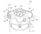
- FIG. 8 is a partially enlarged view of a motorcycle 100 to which a handlebar switch 120 according to a second embodiment of the present invention is applied.
- the motorcycle 100 is a scooter type vehicle having a low floor floor (not shown) on which an occupant can carry a foot, and a leg shield 112 opposed to the leg of the occupant is provided at the top of the low floor floor.
- a lid member 111 of a storage space and a cylinder 110 of an ignition key are attached to the leg shield 112, and a handle cover 102 in which a meter panel 103 is embedded is provided above it.
- the steering wheel cover 102 is an exterior part that covers the steering handle 104 for steering the front wheels from the rear side of the vehicle body, and on the front side of the vehicle body, the front cover 101 for embedding headlights and blinkers faces the steering wheel cover 102 Is attached.
- a starter switch 109 is provided on the handle cover 102 in the vicinity of the handle grip on the right side.
- the handlebar switch 120 does not have separate left and right separate switch housings, and a vertically tilting dimmer switch 107, a swing pressure type near the handle grip on the left side of the handlebar cover 102 as a switch housing A horn switch 106 and a left and right tilt type blinker switch 108 are arranged. These three switches have the same arrangement and structure as those of the first embodiment described above, so that the handleability of the horn switch 106 is enhanced and the handle switch 120 is easily realized so that the horn switch 106 can be easily identified. There is.
- the handlebar switch according to the present invention can be applied regardless of the shape of the switch housing, the form of the vehicle, and the like.
- the shape of the switch housing, the shape and structure of the horn switch, and the structure and number of other switches are not limited to the above-described embodiment, and various changes can be made.
- the horn switch is included in the steering wheel switch on the left side of the vehicle body in the above embodiment, the horn switch can be attached to the steering wheel switch on the right side of the vehicle body.
- the steering wheel switch according to the present invention is not limited to a motorcycle, and may be applied to a three-wheeled vehicle, a four-wheeled vehicle, and the like.
Landscapes
- Engineering & Computer Science (AREA)
- Mechanical Engineering (AREA)
- Rotary Switch, Piano Key Switch, And Lever Switch (AREA)
- Steering Devices For Bicycles And Motorcycles (AREA)
- Steering Controls (AREA)
- Mechanical Control Devices (AREA)
- Push-Button Switches (AREA)
- Mechanisms For Operating Contacts (AREA)
Abstract
Description
9:ハンドルバー
10:ハンドルグリップ
15:操向ハンドル
30:ハンドルスイッチ
31:光軸切り換えスイッチ(他のスイッチ)
32:ホーンスイッチ
32a:車体上方部
32b:車体下方部
32c:車体内方部
32d:車体外方部
32e:操作面
33:ウインカスイッチ(他のスイッチ)
36:揺動軸
37:弾性部材
38:可動接点
39:固定接点
60:ハウジング
61:表側半体
62:裏側半体
85:ピボット軸
D:ハンドルグリップの軸線
G:ピボット軸の中心位置
H:線 1: Motorcycle (vehicle)
9: handlebar 10: handle grip 15: steering handle 30: handle switch 31: light axis changeover switch (other switch)
32:
36: rocking shaft 37: elastic member 38: movable contact 39: fixed contact 60: housing 61: front half 62: back half 85: pivot axis D: handle grip axis G: pivot axis center position H: line
Claims (11)
- ホーンスイッチ(32)と少なくとも1つの他のスイッチ(31,33)とを備えるスイッチハウジング(60)を、ハンドルバー(9)端部に取り付けられるハンドルグリップ(10)に隣接配置した車両のハンドルスイッチ(30)において、
前記ホーンスイッチ(32)は、前記スイッチハウジング(60)の運転者側の正面視方向から投影した際に、前記ハンドルグリップ(10)の軸線(D)と重なる位置で、かつ前記他のスイッチ(31,33)より車体後方側に配設されており、
前記他のスイッチ(31,33)は、前記ホーンスイッチ(32)に対して上下方向にずらして配設されている車両のハンドルスイッチ。 A steering wheel switch of a vehicle, wherein a switch housing (60) comprising a horn switch (32) and at least one other switch (31, 33) is arranged adjacent to a steering wheel grip (10) attached to the end of the steering wheel (9). In (30),
When the horn switch (32) is projected from a front view direction on the driver side of the switch housing (60), the horn switch (32) overlaps the axis (D) of the handle grip (10) and the other switch 31, 33) are disposed on the rear side of the vehicle body,
The other switch (31, 33) is a steering wheel switch of a vehicle, which is disposed vertically offset from the horn switch (32). - 前記ハンドルグリップ(10)を把持しながら操作され、かつピボット軸(85)を中心にして車体前後方向に揺動するブレーキ用またはクラッチ用のレバー(12)が、前記スイッチハウジング(60)に隣接して設けられており、
前記ホーンスイッチ(32)は、前記スイッチハウジング(60)を前記ハンドルグリップ(10)の軸線方向から投影した際に、前記ハンドルグリップ(10)の軸線(D)と前記ピボット軸(85)の中心位置(G)とを結ぶ線(H)と重なる位置に配設されている請求項1に記載の車両のハンドルスイッチ。 A brake or clutch lever (12) which is operated while gripping the handle grip (10) and pivots in the longitudinal direction of the vehicle about a pivot shaft (85) is adjacent to the switch housing (60) Are provided,
The horn switch (32) projects the switch housing (60) from the axial direction of the handle grip (10), the axis (D) of the handle grip (10) and the center of the pivot shaft (85). The steering wheel switch for a vehicle according to claim 1, wherein the steering wheel switch is disposed at a position overlapping a line (H) connecting the position (G). - 前記ホーンスイッチ(32)は、該ホーンスイッチの前記ハンドルグリップ(10)寄りの端部(32d)に設けられた揺動軸(36)を中心として、前記ハンドルグリップ(10)の軸線(D)の方向へ押圧することで揺動するように構成されている請求項1または2に記載の車両のハンドルスイッチ。 The horn switch (32) is an axis (D) of the handle grip (10) about a swing shaft (36) provided at an end (32d) near the handle grip (10) of the horn switch. The steering wheel switch for a vehicle according to claim 1 or 2, wherein the steering wheel switch is configured to swing by pressing in the direction of.
- 前記ホーンスイッチ(32)が、前記スイッチハウジング(60)から外方に突出するように配設されており、
前記スイッチハウジング(60)からの前記ホーンスイッチ(32)の突出量が、前記ハンドルグリップ(10)寄りの端部(32d)から、前記ハンドルグリップ(10)の軸線(D)に沿って車体中央側に向かうにつれて大きくなる請求項3に記載の車両のハンドルスイッチ。 The horn switch (32) is disposed to protrude outward from the switch housing (60),
The amount of protrusion of the horn switch (32) from the switch housing (60) is from the end (32d) near the handle grip (10) along the axis (D) of the handle grip (10) at the center of the vehicle body The steering wheel switch of a vehicle according to claim 3, which becomes larger toward the side. - 前記ホーンスイッチ(32)の突出量が、前記ハンドルグリップ(10)寄りの端部(32d)で略ゼロとなる請求項4に記載の車両のハンドルスイッチ。 The steering wheel switch for a vehicle according to claim 4, wherein the amount of projection of the horn switch (32) is substantially zero at an end (32d) closer to the steering wheel grip (10).
- 前記ホーンスイッチ(32)の操作面(32e)の面積が、前記ハンドルグリップ(10)寄りの端部(32d)から、前記ハンドルグリップ(10)の軸線(D)に沿って車体中央側に向かうにつれて大きくなる請求項3に記載の車両のハンドルスイッチ。 The area of the operation surface (32e) of the horn switch (32) is directed from the end (32d) near the handle grip (10) toward the center of the vehicle along the axis (D) of the handle grip (10) The steering wheel switch of a vehicle according to claim 3, which becomes larger as it becomes larger.
- 前記ホーンスイッチ(32)は、前記ハンドルグリップ(10)の軸線(D)を挟んで上下に対向する2つの輪郭線を有しており、
前記2つの輪郭線の間隔が、前記ハンドルグリップ(10)寄りの端部(32d)から、前記ハンドルグリップ(10)の軸線(D)に沿って車体中央側に向かうにつれて漸次大きくなる請求項3に記載の車両のハンドルスイッチ。 The horn switch (32) has two contour lines which vertically oppose each other across the axis (D) of the handle grip (10),
The distance between the two contours gradually increases from the end (32d) closer to the handle grip (10) toward the center of the vehicle along the axis (D) of the handle grip (10). The steering wheel switch of the vehicle described in. - 前記他のスイッチ(31,33)の輪郭線のうち前記ホーンスイッチ(32)に隣接する一辺(31a,33a)が前記ホーンスイッチ(32)の2つの輪郭線のいずれか一方に沿うように形成されている請求項7に記載の車両のハンドルスイッチ。 Of the contours of the other switch (31, 33), one side (31a, 33a) adjacent to the horn switch (32) is formed along one of the two contours of the horn switch (32) The steering wheel switch of the vehicle according to claim 7.
- 前記ホーンスイッチ(32)の車体内方部(32c)が、前記他のスイッチ(31,33)より車体中央寄りに配設されている請求項1または2に記載の車両のハンドルスイッチ。 The steering wheel switch for a vehicle according to claim 1 or 2, wherein the vehicle body inward portion (32c) of the horn switch (32) is disposed closer to the center of the vehicle body than the other switch (31, 33).
- 前記ホーンスイッチ(32)は、前記ハンドルグリップ(10)の軸線(D)の方向を長手方向とする形状とされている請求項1または2に記載の車両のハンドルスイッチ。 The steering wheel switch for a vehicle according to claim 1 or 2, wherein the horn switch (32) is shaped so that a direction of an axis (D) of the steering wheel grip (10) is a longitudinal direction.
- 前記他のスイッチ(31,33)は、少なくともウインカスイッチ(33)またはヘッドライトのディマースイッチ(31)を含む請求項1または2に記載の車両のハンドルスイッチ。 The steering wheel switch of a vehicle according to claim 1 or 2, wherein the other switch (31, 33) includes at least a blinker switch (33) or a dimmer switch (31) of a headlight.
Priority Applications (6)
| Application Number | Priority Date | Filing Date | Title |
|---|---|---|---|
| CN200980125023.2A CN102105346B (en) | 2008-07-02 | 2009-06-26 | Handle switch for vehicle |
| US13/001,572 US8686305B2 (en) | 2008-07-02 | 2009-06-26 | Handle switch of vehicle |
| BRPI0913645A BRPI0913645B8 (en) | 2008-07-02 | 2009-06-26 | Motorcycle handlebar switch |
| MX2010014143A MX2010014143A (en) | 2008-07-02 | 2009-06-26 | Handle switch for vehicle. |
| ES09773146.7T ES2516016T3 (en) | 2008-07-02 | 2009-06-26 | Vehicle |
| EP09773146.7A EP2292499B1 (en) | 2008-07-02 | 2009-06-26 | Vehicle |
Applications Claiming Priority (2)
| Application Number | Priority Date | Filing Date | Title |
|---|---|---|---|
| JP2008-173329 | 2008-07-02 | ||
| JP2008173329A JP5213551B2 (en) | 2008-07-02 | 2008-07-02 | Vehicle handle switch |
Publications (1)
| Publication Number | Publication Date |
|---|---|
| WO2010001568A1 true WO2010001568A1 (en) | 2010-01-07 |
Family
ID=41465675
Family Applications (1)
| Application Number | Title | Priority Date | Filing Date |
|---|---|---|---|
| PCT/JP2009/002965 WO2010001568A1 (en) | 2008-07-02 | 2009-06-26 | Handle switch for vehicle |
Country Status (9)
| Country | Link |
|---|---|
| US (1) | US8686305B2 (en) |
| EP (1) | EP2292499B1 (en) |
| JP (1) | JP5213551B2 (en) |
| CN (1) | CN102105346B (en) |
| AR (1) | AR072372A1 (en) |
| BR (1) | BRPI0913645B8 (en) |
| ES (1) | ES2516016T3 (en) |
| MX (1) | MX2010014143A (en) |
| WO (1) | WO2010001568A1 (en) |
Families Citing this family (16)
| Publication number | Priority date | Publication date | Assignee | Title |
|---|---|---|---|---|
| EP2657121B1 (en) * | 2012-04-23 | 2015-02-18 | Campagnolo S.r.l. | Bar-end electric actuation device of a bicycle gearshift |
| CN103489732B (en) * | 2013-09-16 | 2015-05-27 | 温州盛世机车业有限公司 | Mini-type combined switch |
| JP6214351B2 (en) * | 2013-11-18 | 2017-10-18 | 朝日電装株式会社 | Switch device for handlebar |
| JP6194271B2 (en) * | 2014-03-28 | 2017-09-06 | 本田技研工業株式会社 | Vehicle handle switch |
| JP1518184S (en) * | 2014-08-29 | 2015-02-23 | ||
| JP1518185S (en) * | 2014-08-29 | 2015-02-23 | ||
| JP2016192252A (en) * | 2015-03-30 | 2016-11-10 | 本田技研工業株式会社 | Vehicular handle switch |
| US9499230B1 (en) * | 2015-05-27 | 2016-11-22 | Sensata Technologies, Inc. | Fixation adapter for handlebar |
| USD841160S1 (en) * | 2016-04-01 | 2019-02-19 | Deka Products Limited Partnership | Endoscope |
| JP1585660S (en) * | 2017-03-24 | 2018-01-09 | ||
| USD856855S1 (en) * | 2018-02-08 | 2019-08-20 | Matthew J Steele | Handlebar switch |
| JP7185789B2 (en) * | 2019-04-04 | 2022-12-07 | ジェイエルジー インダストリーズ インク. | Control station for small vehicles |
| USD913166S1 (en) * | 2019-11-04 | 2021-03-16 | Ktm Ag | Motor vehicle switch |
| USD915950S1 (en) * | 2019-11-04 | 2021-04-13 | Ktm Ag | Motor vehicle switch |
| WO2022074742A1 (en) * | 2020-10-06 | 2022-04-14 | ヤマハ発動機株式会社 | Saddled vehicle |
| US12060130B1 (en) * | 2020-12-28 | 2024-08-13 | Keith Edward Conger | Device and software that provides handlebar control and motorcycle performance data wirelessly to a portable computing device |
Citations (7)
| Publication number | Priority date | Publication date | Assignee | Title |
|---|---|---|---|---|
| JPS63112189U (en) * | 1987-01-14 | 1988-07-19 | ||
| JP2000016366A (en) * | 1998-06-29 | 2000-01-18 | Asahi Denso Co Ltd | Steering wheel switch having choke operating device |
| JP2002324459A (en) * | 2001-04-26 | 2002-11-08 | Asahi Denso Co Ltd | Push switch |
| JP2003312564A (en) * | 2002-04-19 | 2003-11-06 | Yamaha Motor Co Ltd | Handle bar switch fitting structure of motorcycle |
| JP2004224192A (en) * | 2003-01-23 | 2004-08-12 | Asahi Denso Co Ltd | Handle switch |
| JP2004530586A (en) * | 2001-02-15 | 2004-10-07 | マッカリスター デザインズ インコーポレーテッド | Backlit handlebar control assembly |
| JP2005053452A (en) | 2003-07-31 | 2005-03-03 | Daytona:Kk | Handlebar switch |
Family Cites Families (5)
| Publication number | Priority date | Publication date | Assignee | Title |
|---|---|---|---|---|
| JP3662659B2 (en) * | 1996-02-23 | 2005-06-22 | 朝日電装株式会社 | Crimp sliding switch |
| JP2001247070A (en) * | 2000-03-03 | 2001-09-11 | Honda Motor Co Ltd | Switch panel device of saddle riding type vehicle |
| US6538221B1 (en) * | 2000-09-14 | 2003-03-25 | Shimano Inc. | Key guard for a function key on a bicycle control panel |
| JP4580129B2 (en) * | 2001-09-04 | 2010-11-10 | 本田技研工業株式会社 | Turn signal structure of vehicle |
| JP4890074B2 (en) * | 2006-04-03 | 2012-03-07 | 東洋電装株式会社 | Vehicle handle switch device |
-
2008
- 2008-07-02 JP JP2008173329A patent/JP5213551B2/en not_active Expired - Fee Related
-
2009
- 2009-06-26 AR ARP090102374A patent/AR072372A1/en active IP Right Grant
- 2009-06-26 WO PCT/JP2009/002965 patent/WO2010001568A1/en active Application Filing
- 2009-06-26 BR BRPI0913645A patent/BRPI0913645B8/en active IP Right Grant
- 2009-06-26 MX MX2010014143A patent/MX2010014143A/en active IP Right Grant
- 2009-06-26 CN CN200980125023.2A patent/CN102105346B/en active Active
- 2009-06-26 EP EP09773146.7A patent/EP2292499B1/en not_active Not-in-force
- 2009-06-26 ES ES09773146.7T patent/ES2516016T3/en active Active
- 2009-06-26 US US13/001,572 patent/US8686305B2/en not_active Expired - Fee Related
Patent Citations (7)
| Publication number | Priority date | Publication date | Assignee | Title |
|---|---|---|---|---|
| JPS63112189U (en) * | 1987-01-14 | 1988-07-19 | ||
| JP2000016366A (en) * | 1998-06-29 | 2000-01-18 | Asahi Denso Co Ltd | Steering wheel switch having choke operating device |
| JP2004530586A (en) * | 2001-02-15 | 2004-10-07 | マッカリスター デザインズ インコーポレーテッド | Backlit handlebar control assembly |
| JP2002324459A (en) * | 2001-04-26 | 2002-11-08 | Asahi Denso Co Ltd | Push switch |
| JP2003312564A (en) * | 2002-04-19 | 2003-11-06 | Yamaha Motor Co Ltd | Handle bar switch fitting structure of motorcycle |
| JP2004224192A (en) * | 2003-01-23 | 2004-08-12 | Asahi Denso Co Ltd | Handle switch |
| JP2005053452A (en) | 2003-07-31 | 2005-03-03 | Daytona:Kk | Handlebar switch |
Non-Patent Citations (1)
| Title |
|---|
| See also references of EP2292499A4 |
Also Published As
| Publication number | Publication date |
|---|---|
| BRPI0913645B1 (en) | 2019-05-14 |
| JP2010012862A (en) | 2010-01-21 |
| CN102105346A (en) | 2011-06-22 |
| MX2010014143A (en) | 2011-03-04 |
| EP2292499A1 (en) | 2011-03-09 |
| BRPI0913645A2 (en) | 2015-10-13 |
| AR072372A1 (en) | 2010-08-25 |
| CN102105346B (en) | 2014-12-17 |
| JP5213551B2 (en) | 2013-06-19 |
| US20110108397A1 (en) | 2011-05-12 |
| US8686305B2 (en) | 2014-04-01 |
| EP2292499A4 (en) | 2012-06-06 |
| EP2292499B1 (en) | 2014-10-08 |
| ES2516016T3 (en) | 2014-10-30 |
| BRPI0913645B8 (en) | 2022-05-31 |
Similar Documents
| Publication | Publication Date | Title |
|---|---|---|
| WO2010001568A1 (en) | Handle switch for vehicle | |
| JP5403804B2 (en) | Handle switch | |
| US10953947B2 (en) | Handlebar switch | |
| JPH07397Y2 (en) | Switch device for motorcycles, etc. | |
| US9941079B2 (en) | Handle switch for vehicle | |
| US9018551B2 (en) | Handlebar switch for motorcycle | |
| EP3000707B1 (en) | Saddle type vehicle | |
| JP4316179B2 (en) | Handlebar switch case | |
| US9455100B2 (en) | Switch | |
| JP5124855B2 (en) | Handle switch device for motorcycle | |
| JP2016159719A (en) | Screen movable device in saddle-riding type vehicle | |
| WO2022075285A1 (en) | Saddle-ride type vehicle | |
| JPH06227314A (en) | Motor scooter with position lamp | |
| WO2023171442A1 (en) | Vehicle | |
| JP2013071592A (en) | Handle switch device for vehicle | |
| JP2023150200A (en) | Turn signal lamp switch device | |
| JP6461753B2 (en) | Saddle riding | |
| JP4453963B2 (en) | Switch structure for vehicle | |
| JP2023118451A (en) | Switch box and saddle-riding type vehicle | |
| JP3151381B2 (en) | Dimmer switch for bar handle | |
| JP2015067027A (en) | Vehicle handle switch device | |
| JP2016074259A (en) | Handlebar switch system |
Legal Events
| Date | Code | Title | Description |
|---|---|---|---|
| WWE | Wipo information: entry into national phase |
Ref document number: 200980125023.2 Country of ref document: CN |
|
| 121 | Ep: the epo has been informed by wipo that ep was designated in this application |
Ref document number: 09773146 Country of ref document: EP Kind code of ref document: A1 |
|
| WWE | Wipo information: entry into national phase |
Ref document number: 2009773146 Country of ref document: EP |
|
| WWE | Wipo information: entry into national phase |
Ref document number: MX/A/2010/014143 Country of ref document: MX |
|
| NENP | Non-entry into the national phase |
Ref country code: DE |
|
| WWE | Wipo information: entry into national phase |
Ref document number: 342/DELNP/2011 Country of ref document: IN |
|
| WWE | Wipo information: entry into national phase |
Ref document number: 13001572 Country of ref document: US |
|
| ENP | Entry into the national phase |
Ref document number: PI0913645 Country of ref document: BR Kind code of ref document: A2 Effective date: 20101230 |